Embed Size (px)
Citation preview
Marquette University Marquette University
e-Publications@Marquette e-Publications@Marquette
Electrical and Computer Engineering Faculty Research and Publications
Electrical and Computer Engineering, Department of
9-2016
Large-Scale Design Optimization of PM Machines Over a Target Large-Scale Design Optimization of PM Machines Over a Target
Operating Cycle Operating Cycle
Alireza Fatemi Marquette University
Nabeel Demerdash Marquette University, [email protected]
Thomas W. Nehl General Motors
Dan M. Ionel University of Wisconsin - Milwaukee
Follow this and additional works at: https://epublications.marquette.edu/electric_fac
Part of the Computer Engineering Commons, and the Electrical and Computer Engineering Commons
Recommended Citation Recommended Citation Fatemi, Alireza; Demerdash, Nabeel; Nehl, Thomas W.; and Ionel, Dan M., "Large-Scale Design Optimization of PM Machines Over a Target Operating Cycle" (2016). Electrical and Computer Engineering Faculty Research and Publications. 209. https://epublications.marquette.edu/electric_fac/209

Marquette University
e-Publications@Marquette
Electrical and Computer Engineering Faculty Research and Publications/College of Engineering
This paper is NOT THE PUBLISHED VERSION. Access the published version at the link in the citation below.
IEEE Transactions on Industry Applications, Vol. 52, No. 5 (September-October 2016): 3772-3782. DOI. This article is © The Institute of Electrical and Electronics Engineers and permission has been granted for this version to appear in e-Publications@Marquette. The Institute of Electrical and Electronics Engineers does not grant permission for this article to be further copied/distributed or hosted elsewhere without the express permission from The Institute of Electrical and Electronics Engineers.
Large-Scale Design Optimization of PM Machines Over a Target Operating Cycle
Alireza Fatemi Department of Electrical and Computer Engineering, Marquette University, Milwaukee, WI Nabeel A. O. Demerdash Department of Electrical and Computer Engineering, Marquette University, Milwaukee, WI Thomas W. Nehl General Motors Global Research and Development, Warren, MI Dan M. Ionel Department of Electrical and Computer Engineering, University of Kentucky, Lexington, KY
Abstract: A large-scale finite element model-based design optimization algorithm is developed for improving the drive-cycle efficiency of permanent magnet (PM) synchronous machines with wide operating ranges

such as those used in traction propulsion motors. The load operating cycle is efficiently modeled by using a systematic k-means clustering method to identify the operating points representing the high-energy-throughput zones in the torque-speed plane. The machine performance is evaluated over these cyclic representative points using a recently introduced computationally efficient finite element analysis, which is upgraded to include both constant torque and field-weakening operations in the evaluation of the machine performance metrics. In contrast with the common practice, which aims at enhancing the rated performance, the entire range of operation is considered in the present design optimization method. Practical operational constraints imposed by the voltage and current limits of the motor-drive system, excessive PM demagnetization, and torque ripple are accounted for during the optimization process. The convergence to the optimal design solutions is expedited by utilizing a new stochastic optimizer. The developed design algorithm is applicable to any configuration of sinewave-drive PM and synchronous reluctance motors over any conceivable load profile. Its effectiveness is demonstrated by optimizing the well-established benchmark design represented by the Toyota Prius Gen. 2 interior PM motor configuration over a compound operating cycle consisting of common U.S. driving schedules. Multiphysics electromagnetic, thermal, and mechanical performance of the optimized design solutions is discussed in a postdesign optimization stage.
SECTION I. Introduction The Electric symmetry in the stator winding configurations of synchronous machines can be utilized to reduce the computational burden of the electromagnetic finite element analysis (FEA) of permanent magnet (PM) motors [1]. The resulting computationally efficient FEA method (CE-FEA) is especially suitable for modeling and parametric design of PM machines with saturated ferrous cores and complex rotor configurations [2], where analytical modeling approaches fail to produce accurate estimates of various performance metrics of such machines. In [3], automated multiobjective design optimization of PM ac machines has been introduced based on CE-FEA and differential evolution (DE) optimizer. The CE-FEA concept has also been utilized to calculate the rotor magnet losses of concentrated-winding PM synchronous machines [4]. The design optimization method based on CE-FEA and DE has since been used to identify the existing trade-offs in multiobjective design of PM machines [5], or to establish the relative merits of counterpart PM motor topologies [6].
Depending on the particular application, the CE-FEA-based design optimization techniques aim at realizing a set of objectives under certain performance constraints described/embedded in the optimization fitness function [2]–[7]. In line with the common practice, the CE-FEA-based methods evaluate the associated fitness function at the rated load point, i.e., base speed and rated torque without directly incorporating the efficiency requirements of the extended speed range operation into the optimization fitness function.
One of the pioneering finite element (FE)-based design optimization efforts for improving the field-weakening performance was introduced in [8], where example interior PM (IPM) motors were optimized for minimum active volume and maximum normalized characteristic current. Similarly, the idea of equality of characteristic current, ICH, with rated current, IR, was introduced as an additional objective for optimization of IPM motors for enhanced field-weakening performance [7], [9]. In [10], the following objectives were concurrently pursued: 1) maximization of the torque at base and at maximum speeds; and 2) minimization of the weight. Although the equality of ICH and IR was not

directly introduced in the fitness function, excluding efficiency from the objectives resulted in an optimized design in which the two currents were equal [10] .
The equality of ICH and IR improves the torque production capability. However, when the nonlinear and lossy nature of the machine is considered, from the efficiency standpoint, congruity of ICH and IR cannot be the ideal criterion for constant power operation [11], [12]. In [13], maximizing the torque and efficiency at the base and maximum speeds were pursued to simultaneously improve the efficiency and operation range of a concentrated flux IPM motor.
In more recent studies, researchers have attempted to optimize the machine performance for a specific drive cycle [14]–[17]. In [14] and [15], a method known as the cyclic representative points was implemented to efficiently model a target driving cycle by a finite number of torque versus speed points. These points were derived based on the energy distribution function specifically calculated for a given vehicle model and driving cycle. Those investigators subsequently performed the optimization over these cyclic representative points. However, the selection criterion of these points requires a more systematic procedure for identification of the high-energy-throughput zones of the load energy distribution function, especially when more demanding operating cycles are desired. Furthermore, since a large-scale optimization was not pursued, the design space was not fully explored.
Most recently, in [18] a propulsion PM-assisted synchronous reluctance (SyR) motor was optimized using the relatively subjective drive cycle modeling method introduced in [14] and [15]. Nonetheless, because of the computationally demanding nature of the adopted approach, limited number of design variables was treated, i.e., tooth width and slot height. Furthermore, the torque ripple was not included in the optimization process.
In this paper, large-scale design optimization of PM machines for a specific load profile is investigated. The original CE-FEA approach is upgraded to enable fast and high fidelity performance evaluation of the design candidates at any load operating point residing either in the constant torque or extended speed regions. To further increase the computational efficiency of the design optimization, a new stochastic search algorithm, namely a combined multiobjective optimization with DE (CMODE) [19], is adopted. As reported in [20], the CMODE method is especially suitable for design of electric machines as constrained optimization problems.
The presented design optimization method is applicable to interior and surface-mounted PM motors with various slot-pole combinations and rotor magnet layouts, SyR motors, and in essence any PM motor which, through proper drive controls, is energized by sinusoidal terminal currents. Moreover, the design optimization can be performed over any conceivable motor operating cycle, while taking into account the practical operational constraints imposed by the supply voltage and/or the motor current limits [21]. Here, the developed method will be used to optimize the Toyota Prius Gen. 2 IPM motor configuration over a combination of common US driving schedules [22]. This specific motor configuration is chosen here for a twofold purpose. First are the particular features of the V-type IPM motors with distributed windings including saliency and mechanical robustness, which makes them attractive for high-speed operation. Second, to lay the ground for a detailed comparison between the optimization results and the experimental verifications documented in several reports by the research team at Oak Ridge National Laboratory (ORNL), Oak Ridge, TN, USA, during the past years [23]–[25].

Accordingly, the paper consists of six sections. The efficient modeling of the motor load profile is explained in Section II. The FE model of the investigated motor configuration and the control algorithm for derivation of the forcing function for FEA at any load point are discussed in Section III. The optimization algorithm, and the associated objectives and constraints, i.e., fitness function considered for this problem, are described in Section IV. Section V provides the optimization results together with a multiphysics performance comparison between the alternative design solutions. Section VI is dedicated to the conclusions.
SECTION II. Efficient Modeling of the Motor Load Profile In this section, a systematic method is presented for efficient modeling of a given operating cycle using a limited number of load points.
A. The Distribution of the Load Energy Consumption Over the Torque–Speed Plane The first step of the optimization process is the identification of the motor torque and speed profiles for the specific application. In the case study traction motor, numerous factors such as the drivetrain technology, transmission system, energy management unit, and the vehicle-operating mode determine the motor propulsion requirements. Here, the advanced vehicle simulator (ADVISOR) developed by the National Renewable Energy Laboratory is used for modeling the Toyota Prius Gen. 2 vehicle. The motor torque and speed profiles are obtained for a sequence of driving cycles composed of the US Environmental Protection Agency's Urban Dynamometer Driving Schedule (UDDS), Supplemental Federal Test Procedure Driving Schedule (US06), Highway Fuel Economy Test Driving Schedule, Unified Dynamometer Driving Schedule (LA92), see Fig. 1.
Fig. 1. Motor (a) output torque and (b) speed profiles obtained from simulation of the Toyota Prius Gen. 2 using ADVISOR over a combined driving cycle.
From the thermal limit standpoint, the continuous torque can be determined based on the root mean square of the torque profile, such as that shown in Fig. 1(a). The determination of the optimum speed ratio, which is the ratio of maximum speed, 𝜔𝜔max, to base speed, 𝜔𝜔base, depends on many figures of

merit including the system power specifications, total weight, losses, etc. For PM synchronous propulsion motors, the optimum speed ratio falls within a range of 3–4 [26], [27]. Here, considering the speed requirements in Fig. 1(b), and adopting a speed ratio of 4, base and maximum speed values are yielded which are very close to those reported for Toyota Prius Gen. 2, see the first two entries of Table I.
TABLE I Cyclic Representative Points
𝑚𝑚𝑖𝑖 𝑤𝑤(rad/sec) 𝑇𝑇(N ⋅ m) Energy weight 𝑤𝑤base 157 300 𝑤𝑤max 628 50 1 140 21 0.2570 2 311 15 0.2273 3 212 19 0.1366 4 74 123 0.1338 5 403 15 0.1265 6 151 288 0.0687 7 44 36 0.0501
Using the motor output torque and speed profiles in Fig. 1, the absolute value of the energy distribution over the torque–speed plane can be calculated as shown in Fig. 2(a). The motor operating regions, constant torque and constant power, can be recognized in the distribution of these load points in Fig. 2(b). For the investigated compound driving cycle, these points are scattered throughout the torque–speed plane with a larger concentration in the high-speed low-torque vicinity which underscores the importance of efficient operation in the extended speed range.
Fig. 2. Load energy consumption over the torque–speed plane. (a) Isometric view and (b) bird's-eye view.

B. Cyclic Representative Points For computational reasons, the swarm of the operating points in the load energy distribution needs to be modeled by a limited number of so-called cyclic representative load points which should convey the main features of the driving cycle in a computationally efficient manner. Specifically, these representative points should indicate (a) the speed and torque at the high-energy-throughput operating zones of the torque–speed plane, and (b) the energy weights associated with these zones which is the measure of significance of these zones in the evaluation of the motor drive-cycle efficiency.
A systematic method of quantization that is popular for cluster analysis in data mining known as the k -means clustering algorithm [28] is utilized for modeling the load operating cycle. Using this method, all the 𝑛𝑛 observations in the energy function (𝑥𝑥1, … , 𝑥𝑥𝑛𝑛) can be partitioned into 𝑘𝑘 ≤𝑛𝑛 clusters (𝑠𝑠1, … , 𝑠𝑠𝑘𝑘) in which each observation belongs to the cluster with the nearest mean (𝑚𝑚1, … ,𝑚𝑚𝑘𝑘), serving as the prototype of the cluster. The standard algorithm used here has two iterative steps, the assignment step and the update step.
In the first step, each observation, 𝑥𝑥𝑝𝑝, is assigned to the cluster, 𝑠𝑠𝑖𝑖, with the nearest mean, 𝑚𝑚𝑖𝑖, according to
𝑠𝑠𝑖𝑖(𝑡𝑡) = {𝑥𝑥𝑝𝑝 ∥ 𝑥𝑥𝑝𝑝 − 𝑚𝑚𝑖𝑖
(𝑡𝑡) ∥2≤∥ 𝑥𝑥𝑝𝑝 − 𝑚𝑚𝑗𝑗(𝑡𝑡) ∥2 ∀𝑗𝑗,
1 ≤ 𝑗𝑗 ≤ 𝑘𝑘}
(1)
where 𝑡𝑡 is the iteration count number. The means for the initial iteration can be chosen randomly.
In the update step, the centroids of the observations in the new clusters given in (2) are designated as the new means. These assignment and update steps are iteratively repeated until convergence is reached, i.e., until the assignments in (1) do not change
𝑚𝑚𝑖𝑖𝑡𝑡+1 =
1
∣ 𝑆𝑆𝑖𝑖(𝑡𝑡) ∣
� 𝑥𝑥𝑗𝑗𝑥𝑥𝑗𝑗∈𝑆𝑆𝑖𝑖
𝑡𝑡
.
(2)
Using the k-means algorithm, first the normalized energy distribution function is partitioned into a limited number of clusters, the means of which yield the representative torque–speed point of that cluster. Thereafter, the energy weights of each representative point are computed based on the average energy consumed in the corresponding cluster.
The cyclic representative points and their associated energy weights for the investigated operating cycle are shown in Fig. 3. These load points which will be used in the evaluation of the motor performance during the optimization process, along with two critical load points from the design requirements, i.e., required torque at base and maximum speeds are listed in Table I . A larger number of clusters would provide a more accurate approximation of the energy distribution function at the

cost of diminished computational efficiency since the performance evaluation is carried out over every individual cyclic representative point.
Fig. 3. Calculation of the cyclic representative points and their associated energy weights using k -means algorithm with seven clusters (a) isometric view and (b) bird's-eye view. The numbers next to the means of the clusters indicate their ranks according to their energy weights, see Table I.
SECTION III. IPM Motor Model The two-dimensional (2-D) CE-FEA-based model of the IPM motor and computation of its performance metrics over the representative load points are discussed in this section.
A. Parametrized FE Model The FE model of the Prius 50 hp 48-slot 8-pole IPM motor with single-layer v-type sintered NdFeB magnets has been set up in ANSYS Maxwell. The parameterized cross section of Fig. 4 consists of ten independent design variables, which are rationalized and confined according to Table II so as to avoid geometric conflicts between the structures of various components of the motor. The stator outer and the rotor inner diameters are fixed to 260 and 111 mm, respectively.

Fig. 4. Cross section of the parameterized model of the studied IPM motor comprising ten independent design variables, see Table II.
TABLE II Independent Design Variables and Their Bounds
There are two additional variables which are determined based on the independent design parameters. First is the active stack length of the laminations and rotor PMs, which are scaled to produce the peak torque at the maximum stator winding current density. Second is the thickness of the rotor bridges, which is adjusted whenever necessary to withstand the centrifugal forces at the maximum rotational speed [29].
B. Performance Evaluation Over Representative Points The motor performance should be evaluated over the cyclic representative points as most of the power is consumed or generated at these points. This requires careful control of the machine excitation current for production of maximum torque per ampere (MTPA) under performance constraints imposed either by the motor-rated current in the constant torque region, or by the maximum output voltage of the supply in the constant power region.
Parameter (𝑥𝑥𝑖𝑖) Description 𝑥𝑥𝑖𝑖,𝑚𝑚𝑖𝑖𝑛𝑛 𝑥𝑥𝑖𝑖,𝑚𝑚𝑚𝑚𝑥𝑥 𝑘𝑘𝑠𝑠𝑖𝑖 𝑟𝑟𝑠𝑠𝑖𝑖 /𝑟𝑟𝑠𝑠𝑠𝑠 0.6 0.7 ℎ𝑔𝑔 Fig. 4 0.7 mm 2.5 mm 𝑘𝑘𝑤𝑤𝑡𝑡 𝑤𝑤𝑡𝑡 /𝑤𝑤𝑠𝑠𝑚𝑚 0.35 0.75 𝑘𝑘𝑤𝑤𝑡𝑡𝑡𝑡 𝑤𝑤𝑡𝑡𝑖𝑖𝑝𝑝 /(𝑤𝑤𝑠𝑠𝑠𝑠 + 𝑤𝑤𝑡𝑡𝑖𝑖𝑝𝑝 )𝑏𝑏 0.3 0.8 𝑘𝑘𝑑𝑑𝑝𝑝𝑝𝑝 𝑑𝑑𝑝𝑝𝑚𝑚 /𝑑𝑑𝑝𝑝𝑚𝑚,𝑚𝑚𝑚𝑚𝑥𝑥 0.25 0.50 𝑘𝑘𝑤𝑤𝑝𝑝𝑝𝑝 𝑤𝑤𝑝𝑝𝑚𝑚 /𝑤𝑤𝑝𝑝𝑚𝑚,𝑚𝑚𝑚𝑚𝑥𝑥 0.80 0.93 𝑘𝑘𝑤𝑤𝑞𝑞 𝑤𝑤𝑞𝑞/𝑤𝑤𝑞𝑞,𝑚𝑚𝑚𝑚𝑥𝑥 0.5 0.9 ℎ𝑝𝑝𝑚𝑚 Fig. 4 3.8 mm 9.0 mm 𝛼𝛼𝑝𝑝𝑚𝑚 Fig. 4 20 deg. 32 deg. ℎ𝑦𝑦 Fig. 4 13 mm 25 mm

To perform the FEA, the magnitude and phase angle of the excitation current needs to be determined for each individual design candidate at each representative load point. Accurate estimation of the optimum current density and its advanced angle is imperative in order to ensure a reliable performance comparison between the design candidates. The linear inductance-based models for IPM machines fail to accurately predict the machine behavior when saturation and cross-saturation phenomena are prevalent [16], [30]. In Fig. 5, the predictions of the produced average torque and the induced voltage of the Toyota Prius IPM motor are compared over the full range of excitation current between the linear parameter model based on unsaturated inductances and the actual values obtained from FEA. It can be seen in Fig. 5, that the estimation error steadily creeps up as the current density increases. This error is more evident along the q-axis due to higher permeance of the q-path, and due to the demagnetizing effect of the d-axis current.
Fig. 5. Effects of saturation and cross saturation in prediction of (a) torque and (b) induced voltages over the full range of excitation current.
A new numerical method with built-in control to conform to the motor-drive system voltage and current ratings is developed here. For each design candidate, CE-FEA with reduced number of solutions is performed for various stator excitation currents. The d- and q-axes flux-linkages, 𝜆𝜆𝑑𝑑 and λq, are sampled as the current vector sweeps the second quadrant of the d –q plane, and are stored in look-up tables. Subsequently, the fundamental components of the steady-state torque, 𝑇𝑇, and induced voltage in the stator winding, 𝑣𝑣𝑅𝑅, can be calculated using (3) and (4), respectively,
𝑇𝑇 =32𝑃𝑃2
(𝜆𝜆𝑑𝑑𝐼𝐼𝑞𝑞 − 𝜆𝜆𝑞𝑞𝐼𝐼𝑑𝑑)
𝑣𝑣𝑅𝑅 = 𝜔𝜔𝑒𝑒�(𝜆𝜆𝑑𝑑2 + 𝜆𝜆𝑞𝑞2)
(3)(4)
where 𝑃𝑃 is the number of poles, and 𝜔𝜔𝑒𝑒 is the motor speed in electrical rad/s.
The maximum torque per unit stack length corresponding to the maximum current density in the stator winding, 𝐽𝐽max, indicates the torque production capability of the design candidate. The machine stack length, and the torque and induced voltage look-up tables are scaled proportionally for production of the required torque at the base speed corresponding to a current density of 𝐽𝐽max, which is assumed to be the same for all the design candidates and is determined in reference to the cooling system specifications. Here, based on the original Toyota Prius motor design, 𝐽𝐽max is considered to be 16A/mm2 for producing a torque of 300 Nm.
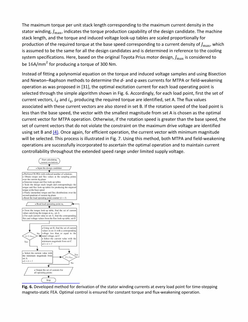
Instead of fitting a polynomial equation on the torque and induced voltage samples and using Bisection and Newton–Raphson methods to determine the d- and q-axes currents for MTPA or field-weakening operation as was proposed in [31], the optimal excitation current for each load operating point is selected through the simple algorithm shown in Fig. 6. Accordingly, for each load point, first the set of current vectors, 𝑖𝑖𝑑𝑑 and 𝑖𝑖𝑞𝑞, producing the required torque are identified, set A. The flux values associated with these current vectors are also stored in set B. If the rotation speed of the load point is less than the base speed, the vector with the smallest magnitude from set A is chosen as the optimal current vector for MTPA operation. Otherwise, if the rotation speed is greater than the base speed, the set of current vectors that do not violate the constraint on the maximum drive voltage are identified using set B and (4). Once again, for efficient operation, the current vector with minimum magnitude will be selected. This process is illustrated in Fig. 7. Using this method, both MTPA and field-weakening operations are successfully incorporated to ascertain the optimal operation and to maintain current controllability throughout the extended speed range under limited supply voltage.
Fig. 6. Developed method for derivation of the stator winding currents at every load point for time-stepping magneto-static FEA. Optimal control is ensured for constant torque and flux-weakening operation.
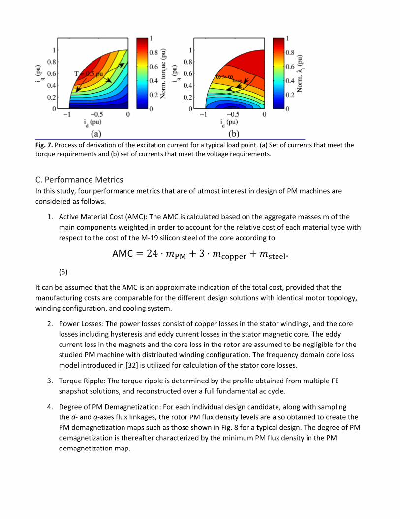
Fig. 7. Process of derivation of the excitation current for a typical load point. (a) Set of currents that meet the torque requirements and (b) set of currents that meet the voltage requirements.
C. Performance Metrics In this study, four performance metrics that are of utmost interest in design of PM machines are considered as follows.
1. Active Material Cost (AMC): The AMC is calculated based on the aggregate masses m of the main components weighted in order to account for the relative cost of each material type with respect to the cost of the M-19 silicon steel of the core according to
AMC = 24 ⋅ 𝑚𝑚PM + 3 ⋅ 𝑚𝑚copper + 𝑚𝑚steel. (5)
It can be assumed that the AMC is an approximate indication of the total cost, provided that the manufacturing costs are comparable for the different design solutions with identical motor topology, winding configuration, and cooling system.
2. Power Losses: The power losses consist of copper losses in the stator windings, and the core losses including hysteresis and eddy current losses in the stator magnetic core. The eddy current loss in the magnets and the core loss in the rotor are assumed to be negligible for the studied PM machine with distributed winding configuration. The frequency domain core loss model introduced in [32] is utilized for calculation of the stator core losses.
3. Torque Ripple: The torque ripple is determined by the profile obtained from multiple FE snapshot solutions, and reconstructed over a full fundamental ac cycle.
4. Degree of PM Demagnetization: For each individual design candidate, along with sampling the d- and q-axes flux linkages, the rotor PM flux density levels are also obtained to create the PM demagnetization maps such as those shown in Fig. 8 for a typical design. The degree of PM demagnetization is thereafter characterized by the minimum PM flux density in the PM demagnetization map.

Fig. 8. PM demagnetization maps of a typical motor for PMs that are located at (a) the leading end and (b) the trailing end with respect to the rotor motion for motoring operation.
The thermal aspect of the design is indirectly addressed in the optimization process by confining the highest current density in the stator winding to that reported for the Toyota Prius IPM motor. In general, the optimized designs are expected to be more efficient than the original design, ensuring that the cooling system can properly conduct the power losses to the ambient surroundings. Still, the thermal performance of the most promising design candidates are investigated over a rigorous driving cycle in a postoptimization stage.
From the mechanical design standpoint, the thickness of the rotor bridges is adjusted when required to withstand the maximum tangential stress acting on these bridges. This adjustment is done using approximate calculations of the centrifugal forces based on the material properties and the shape on the rotor pole-pieces. Minimum thickness is desired for efficient utilization of magnet flux linkage and optimal electromagnetic performance. A postoptimization mechanical FEA is conducted on the selected optimized designs to make sure they pass this criterion.
SECTION IV. Drive-Cycle Optimization A. Design Optimization Algorithm The high-level flowchart of the steps of the developed algorithm for optimization of an electric machine over a target operating cycle is shown in Fig. 9. Following the identification of the representative operating points using the clustering method described in Section II, for each design candidate, the excitation currents at the cyclic representative points are calculated using the numerical method developed in Section III-B. Subsequently, a detailed FEA is carried out over each individual load point using the fast and high fidelity CE-FEA simulations. Accordingly, the saturation and cross saturation are considered both in determining the excitation current and in calculating the machine performance over each representative load point.

Fig. 9. The flowchart of steps of the overall optimization algorithm.
The first iteration of the design candidates is generated randomly with respect to the designated bounds of the design parameters such as those in Table II. The subsequent iterations are followed by a CMODE-type search algorithm [19]. The details of the CMODE-type optimization and its advantages over the conventional DE have been previously discussed in [20] for design optimization of PM motors at the rated operating point. Here, this search algorithm is applied to optimization of PM machines at multiple operating points.
In each iteration of the CMODE-type optimization process, similar to other evolutionary algorithms, an offspring population competes with the parent population according to a fitness function, i.e., a set of objectives and a set of constraints. For optimization of the studied PM machine for traction applications, the following objectives are considered here: 1) minimization of the AMC given in (5); and 2) minimization of the aggregate weighted loss per output power Pw defined in
𝑃𝑃𝑤𝑤 = �(𝑃𝑃copper,𝑖𝑖 + 𝑃𝑃core,𝑖𝑖)𝑖𝑖
⋅ 𝑤𝑤𝑖𝑖/(𝑇𝑇𝑖𝑖𝜔𝜔𝑖𝑖),
(6)
where 𝑤𝑤𝑖𝑖 is the energy weight of the 𝑖𝑖th load point, and 𝑤𝑤𝑖𝑖 is the rotor speed in mech ⋅rad/s.
Furthermore, the following performance constraints are imposed: 1) less than 25% torque ripple at the rated operating point; and 2) less than 33% PM demagnetization at any point on the PM demagnetization maps.
It has been illustrated in [12] that when the nonlinear and lossy nature of the machine is considered, despite a common notion in the literature [7], [33], the congruity of the characteristic current ICH and the rated current 𝐼𝐼𝑅𝑅 cannot be the ideal criterion for constant power operation from the efficiency standpoint. Here, instead of introducing such criterion into the optimization fitness function, the

torque production capability of every design candidate is checked at ωmax. The designs failing to produce the desired torque under the rated current and voltage constraints are accordingly penalized.
B. Computational Complexity of the Optimization Algorithm According to the algorithm in Fig. 9, the overall optimization process consists of three stages, preprocessing, loop iteration, and postprocessing. The computational burden of the loop iteration stage overshadows that of the other two and is divided between three subroutines: 1) generation of the torque and flux look-up tables for calculation of the excitation current; 2) performance evaluation over representative load points; and 3) determination of the superior design candidates. The first two subroutines involve FEA, and thus are more computationally demanding. For generating relatively accurate torque and flux look-up tables, 25 sample current vectors are recommended, which can be distributed evenly, or can be skewed toward the negative d-axis to better capture the smaller flux linkage quantities in this vicinity. Using CE-FEA, as few as one FE solution can be used for each sample point to extract the fundamental values of torque and fluxes. Depending on the pole-slot combination, a larger number of FE solutions are required for calculation of torque ripple and core losses over each representative load point. Nonetheless, CE-FEA can be still utilized to significantly expedite the simulation time up to two orders of magnitude when compared to time-stepping transient FEA [1], [2]. The simulations can be continued until a well-defined Pareto front is acquired. Using CMODE-type optimization, this can be achieved within a smaller number of design evaluations [20].
SECTION V. Optimization Results The optimization was carried out over 10 000 designs using eight simultaneous processing units on a desktop workstation. The global minimum of the design space and accordingly optimal design solutions were identified within the first few hundred design evaluations, in this case in less than 24 h. However, the optimization was continued over a large number of design candidates to capture a very detailed Pareto front [20] . The performance of the design solutions which pass the constraints on the PM demagnetization and torque ripple are shown in Fig. 10(a) and (b). Using the same simulation methodology, the Toyota Prius IPM motor performance, denoted by P, is also evaluated and displayed along with other results in Fig. 10. It can be seen that the Prius design is adjacent to the Pareto-optimal designs at the high-loss, low-cost vicinity. The ability of the developed design optimization package in providing design solutions comparable to the Prius design should be noted. Furthermore, there are other design alternatives that, at a slightly higher cost, demonstrate better performance in terms of aggregate power losses. Two of these design candidates specified by D1 and D2 in Fig. 10 are selected for further multiphysics investigation.
Fig. 10. Optimization results over an overall of 10 000 design solutions illustrating the (a) minimum flux density of the rotor PMs and (b) torque ripple.

A. Electromagnetic Performance The cross sections of the three design candidates, D1, P, and D2, and their performance metrics, normalized with respect to the Prius motor design, are shown in Fig. 11. In Fig. 11(b), the three loss components, are the sum of the respective losses over the representative load points weighted by their associated energy weights. Furthermore, the total harmonic distortion of the induced electromotive force, and the torque ripple are considered at the rated load point.
Fig. 11. Comparison of the selected designs. (a) Cross sections and (b) their performance metrics.
The efficiency maps of the three designs is computed by FEA of 1600 sample load points equidistantly distributed throughout the torque–speed plane, see Fig. 12. The excitation current at each sample point is computed under optimal voltage and current control using the method developed in Section III-B. The efficiency maps should be examined in two aspects: first, the highest achievable efficiency, and second, the extended range of high-efficiency contours. The latter is of significant importance for motor designs in traction applications, or in general for applications in which the motor is to be operated at various load operating points.

Fig. 12. Efficiency maps obtained by FE analysis for 1600 sample points on the torque–speed plane under optimal voltage and current control: (a) D1; (b) P; and (c) D2.
To verify the validity of the simulations, the experimentally obtained efficiency map of the Prius motor reported by the ORNL research team is presented in Fig. 13. The slight discrepancy between the efficiency maps in Figs. 13 and 12(b) can be attributed to the loss components that were not addressed in our 2-D FE calculations including rotor core losses, eddy current losses in the magnets, unaccounted temperature variations, and ac conductor losses. Moreover, the excitation current was assumed to be sinusoidal over the entire operating region ignoring the time harmonics introduced by the inverter pulse width modulation specifically in the field-weakening region. Nonetheless, the simulation results show very close correlation to the experimental results. Correlation of the three designs not only indicates the goodness of the original Prius motor design but also confirms the veracity of the developed design optimization algorithm.
Fig. 13. Tested efficiency map of the Toyota Prius Gen. 2 IPM motor reported by the research team at ORNL.

B. Thermal Performance To compare thermal performance of the counterpart design solutions relative to each other, a typical liquid-based cooling system with oil-forced convection through the housing water-jacket was developed in Motor-CAD. The analysis is based on a lumped thermal network model as shown in Fig. 14. The coolant fluid is ethylene glycol compound with 0.375 W/m⋅C thermal conductivity, 1045 kg/m3 density, and 0.0008987 kg/m/s dynamic viscosity. A constant volume flow rate of 9 l/min at an inlet temperature of 105 ∘C was considered for the fluid.
Fig. 14. Lumped thermal network model of the motor cooling system developed in Motor-CAD.
The temperatures of various motor components were obtained for the rigorous US06 driving cycle which is characterized by frequent acceleration and deceleration at various torque and speed levels. It can be seen in Fig. 15 that with identical cooling systems, the temperatures of the stator windings, rotor PMs, housings, and bearings in the P and D1 counterpart designs closely correspond. These temperatures are slightly lower in the D2 design due to the higher efficiency of this design over a broader range of operation as illustrated in Fig. 12(c). The lower operating temperatures can extend the lifetime of motor D2, and thus justify the increased material cost of this design.

Fig. 15. Peak temperatures of (a) stator windings, (b) rotor PMs, (c) active housings, and (d) bearings of the counterpart designs evaluated over US06 driving cycle.
C. Stress Analysis of the Rotor Bridges The mechanical stresses on the rotor bridges are mainly due to the centrifugal forces resulting from cavities housing the PMs in the rotor structure [29]. A detailed static structural FEA is carried out in ANSYS under steady-state maximum speed of 6000 r/min. It is assumed that forces of electromagnetic, vibration, and rotor dynamic origins are negligible. Furthermore, it is assumed that the rotor PMs are not bonded to the cavities since the bonding strength is not permanently constant and diminishes over time. In the analysis, the mass densities of the rotor laminations and NdFeB magnets are 7850 and 7500 kg/m3, respectively. As can be seen in Fig. 16, the results of the structural analysis demonstrate that the von-Mises stress throughout the rotor structures of the selected optimized D1 and D2 designs are comparable to that of the original P design, and are less than the yield strength of laminations, which is 350 MPa.
Fig. 16. Von-Mises stress throughout the rotor structure of the counterpart designs.
SECTION VI. Conclusion A novel automated design methodology for optimization of PM synchronous machines for an application-specific operating cycle was introduced. The developed method provides a systematic approach for fast and high fidelity design optimization of PM machines with wide ranges of operation. The constraints imposed either by the ampere-loading or by the limited drive voltage were fully integrated into the performance evaluation process, thus enabling the design optimization throughout the constant-torque and constant-power operating regions. Furthermore, the effects of magnetic saturation and cross saturation were thoroughly taken into account both in determining the current excitation of the stator winding at any load operating point, and in calculation of the performance metrics.
Utilizing the k-means clustering algorithm, a systematic method was devised for efficient modeling of the motor operating cycle. The resultant cyclic representative points embody the operation zones of the torque–speed plane through which the majority of the electric energy is consumed. Accordingly, the weighted losses are derived and incorporated in assessing the drive-cycle efficiency of the design candidates in the introduced optimization algorithm.
The large-scale CMODE-type design optimization approach was successfully performed on the Toyota Prius Gen. 2 IPM traction motor, and the results were verified through multiphysics performance analysis of the optimized designs.
ACKNOWLEDGMENT The authors would like to thank ANSYS, Inc., and Motor Design Limited for the software support.
References 1. D. Ionel and M. Popescu, "Finite element surrogate model for electric machines with revolving field:
Application to IPM motors", IEEE Trans. Ind. Appl., vol. 46, no. 6, pp. 2424-2433, Nov./Dec. 2010.
2. G. Sizov, D. Ionel and N. Demerdash, "Modeling and parametric design of permanent-magnet AC machines using computationally efficient finite-element analysis", IEEE Trans. Ind. Electron., vol. 59, no. 6, pp. 2403-2413, Jun. 2012.
3. G. Sizov, P. Zhang, D. Ionel, N. Demerdash and M. Rosu, "Automated multi-objective design optimization of PM AC machines using computationally efficient FEA and differential evolution", IEEE Trans. Ind. Appl., vol. 49, no. 5, pp. 2086-2096, Sep. 2013.
4. P. Zhang, G. Sizov, J. He, D. Ionel and N. Demerdash, "Calculation of magnet losses in concentrated-winding permanent-magnet synchronous machines using a computationally efficient finite-element method", IEEE Trans. Ind. Appl., vol. 49, no. 6, pp. 2524-2532, Nov./Dec. 2013.
5. P. Zhang, G. Sizov, M. Li, D. Ionel, N. Demerdash, S. Stretz, et al., "Multi-objective tradeoffs in the design optimization of a brushless permanent-magnet machine with fractional-slot concentrated windings", IEEE Trans. Ind. Appl., vol. 50, no. 5, pp. 3285-3294, Sep./Oct. 2014.
6. P. Zhang, G. Sizov, D. Ionel and N. Demerdash, "Establishing the relative merits of interior and spoke-type permanent-magnet machines with ferrite or NDFEB through systematic design optimization", IEEE Trans. Ind. Appl., vol. 51, no. 4, pp. 2940-2948, Jul./Aug. 2015.

7. P. Zhang, D. Ionel and N. Demerdash, "Saliency ratio and power factor of IPM motors optimally designed for high efficiency and low cost objectives", Proc. IEEE Energy Convers. Congr. Expo., pp. 3541-3547, Sep. 2014.
8. D. Zarko, D. Ban and T. A. Lipo, "Design optimization of interior permanent magnet (IPM) motors with maximized torque output in the entire speed range", European Conf. Power Electron. Appl., pp. 10, 2005.
9. G. Pellegrino and F. Cupertino, "IPM motor rotor design by means of FEA-based multi-objective optimization", Proc. IEEE Int. Symp. Ind. Electron., pp. 1340-1346, 2010.
10. M. Barcaro, N. Bianchi and F. Magnussen, "Permanent-magnet optimization in permanent-magnet-assisted synchronous reluctance motor for a wide constant-power speed range", IEEE Trans. Ind. Electron., vol. 59, no. 6, pp. 2495-2502, Jun. 2012.
11. S. Morimoto, S. Ooi, Y. Inoue and M. Sanada, "Experimental evaluation of a rare-earth-free PMASynRM with ferrite magnets for automotive applications", IEEE Trans. Ind. Electron., vol. 61, no. 10, pp. 5749-5756, Oct. 2014.
12. A. Fatemi, N. Demerdash and D. Ionel, "Design optimization of IPM machines for efficient operation in extended speed range", Proc. Transp. Electrific. Conf. Expo., pp. 1-8, 2015.
13. J. hee Lee and B.-I. Kwon, "Optimal rotor shape design of a concentrated flux IPM-type motor for improving efficiency and operation range", IEEE Trans. Magn., vol. 49, no. 5, pp. 2205-2208, May 2013.
14. J. Wang, X. Yuan and K. Atallah, "Design optimization of a surface-mounted permanent-magnet motor with concentrated windings for electric vehicle applications", IEEE Trans. Veh. Technol., vol. 62, no. 3, pp. 1053-1064, Mar. 2013.
15. P. Lazari, J. Wang and L. Chen, "A computationally efficient design technique for electric-vehicle traction machines", IEEE Trans. Ind. Appl., vol. 50, no. 5, pp. 3203-3213, Sep. 2014.
16. J. Goss, P. Mellor, R. Wrobel, D. Staton and M. Popescu, "The design of ac permanent magnet motors for electric vehicles: A computationally efficient model of the operational envelope", Proc. 6th IET Int. Conf. Power Electron. Mach. Drives, pp. 1-6, 2012.
17. J. Goss, R. Wrobel, P. Mellor and D. Staton, "The design of ac permanent magnet motors for electric vehicles: A design methodology", Proc. IEEE Int. Elect. Mach. Drives Conf., pp. 871-878, 2013.
18. E. Carraro, M. Morandin and N. Bianchi, "Traction PMASR motor optimization according to a given driving cycle", IEEE Trans. Ind. Appl., vol. 52, no. 1, pp. 209-216, Jan./Feb. 2016.
19. Y. Wang and Z. Cai, "Combining multiobjective optimization with differential evolution to solve constrained optimization problems", IEEE Trans. Evol. Comput., vol. 16, no. 1, pp. 117-134, Feb. 2012.
20. A. Fatemi, D. M. Ionel, N. A. O. Demerdash and T. W. Nehl, "Fast multi-objective CMODE-type optimization of PM machines using multicore desktop computers", IEEE Trans. Ind. Appl..
21. T. Jahns, "Flux-weakening regime operation of an interior permanent-magnet synchronous motor drive", IEEE Trans. Ind. Appl., vol. IA-23, no. 4, pp. 681-689, Jul. 1987.
22. A. Fatemi, N. A. O. Demerdash, D. M. Ionel and T. W. Nehl, "Large-scale electromagnetic design optimization of PM machines over a target operating cycle", Proc. Energy Convers. Congr. Expo., pp. 4383-4390, 2015.
23. M. Olszewski, "Evaluation of 2004 Toyota Prius hybrid electric drive system", Sep. 2004. 24. M. Olszewski, "Evaluation of the 2007 Toyota Camry hybrid synergy drive system", Apr. 2008.

25. J. Miller, "Oak ridge national laboratory annual progress report for the power electronics and electric motors program", Nov. 2013.
26. E. H. M and J. C. Balda, "Permanent magnet synchronous motor drive for hev propulsion: Optimum speed ratio and parameter determination", Proc. IEEE 56th Veh. Technol. Conf., vol. 3, pp. 1500-1504, 2002.
27. Z. Rahman, K. Butler and M. Ehsani, "Effect of extended-speed constant-power operation of electric drives on the design and performance of ev propulsion system", Soc. Auto. Eng. Inc. Future Car Congr., 2000.
28. S. Z. Selim and M. A. Ismail, "K-means-type algorithms: A generalized convergence theorem and characterization of local optimality", IEEE Trans. Pattern Anal. Mach. Intell., vol. PAMI-6, no. 1, pp. 81-87, Jan. 1984.
29. E. Lovelace, T. Jahns, T. Keim and J. H. Lang, "Mechanical design considerations for conventionally laminated high-speed interior pm synchronous machine rotors", IEEE Trans. Ind. Appl., vol. 40, no. 3, pp. 806-812, May 2004.
30. B. Stumberger, G. Stumberger, D. Dolinar, A. Hamler and M. Trlep, "Evaluation of saturation and cross-magnetization effects in interior permanent-magnet synchronous motor", IEEE Trans. Ind. Appl., vol. 39, no. 5, pp. 1264-1271, Sep./Oct. 2003.
31. L. Chen, J. Wang, P. Lazari and X. Chen, "A computationally efficient multi-physics optimization technique for permanent magnet machines in electric vehicle traction applications", Proc. Energy Convers. Congr. Expo., pp. 1644-1650, 2015.
32. D. Ionel, M. Popescu, M. McGilp, T. Miller, S. Dellinger and R. Heideman, "Computation of core losses in electrical machines using improved models for laminated steel", IEEE Trans. Ind. Appl., vol. 43, no. 6, pp. 1554-1564, Nov. 2007.
33. R. Schiferl and T. Lipo, "Power capability of salient pole permanent magnet synchronous motors in variable speed drive applications", IEEE Trans. Ind. Appl., vol. 26, no. 1, pp. 115-123, Jan. 1990.