Embed Size (px)
Citation preview
Large deflection analysis of planar solids
based on the Finite Particle Method
Presenter: Ying Yu
Advisors: Prof. Glaucio H. Paulino
Prof. Yaozhi Luo
Date: July 17th
1 Department of Civil and Environmental Engineering, University
of Illinois at Urbana-Champaign, U.S. & NSF
2 Space Structures Research Center, Zhejiang University, China
10th US National Congress on Computational Mechanics
1, 2
1
2
2
Motivation of the Finite Particle Method (FPM)
Fundamentals of the FPM
Numerical Examples
Concluding Remarks
Future Work
Outline
[email protected] 10th US National Congress on Computational Mechanics
3
Structural nonlinear problems:
— large deformation, large rotation
Discontinuous problems:
— fracture, collapse, fragmentation
Motivation of the FPM
[email protected] 10th US National Congress on Computational Mechanics
Methods:
Finite Element Method (FEM):
— general method
Mesh-free Methods: (DEM, SPH, and others)
— suited for particulate material, such as sand and concrete
4
Finite Particle Method (FPM)
Based on Vector Mechanics
The procedure of this method is simple and unified. Without
special considerations, strong nonlinear and discontinuous
problems can be solved.
Ting, E.C., Shi, C., Wang, Y.K.: Fundamentals of a vector form intrinsic finite
element: Part I. Basic procedure and a planar frame element. J. Mech. 20, 113–
122 (2004)
Motivation of the FPM
[email protected] 10th US National Congress on Computational Mechanics
5
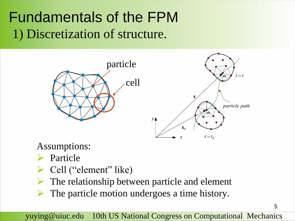
Assumptions:
Particle
Cell (―element‖ like)
The relationship between particle and element
The particle motion undergoes a time history.
[email protected] 10th US National Congress on Computational Mechanics
Fundamentals of the FPM1) Discretization of structure.
cell
particle
6
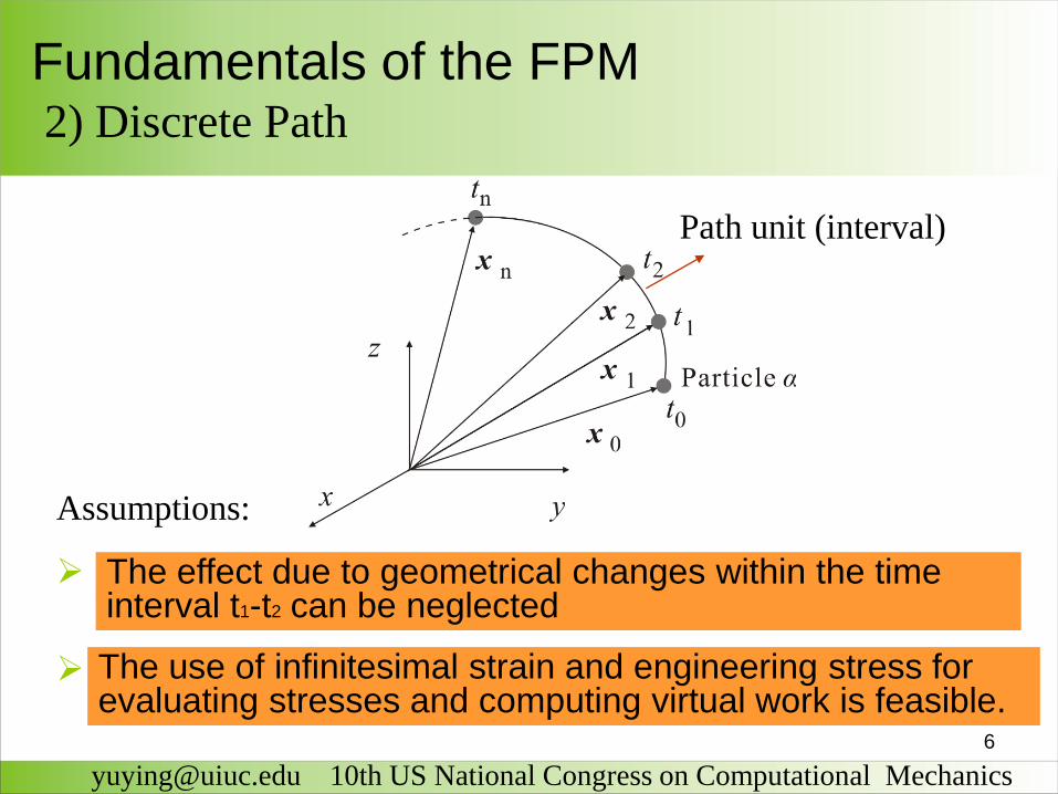
Assumptions:
The reference configuration for stress analysis of a continuous body is its configuration at time t1.
The deformation of the continuous body is infinitesimal (small deformation) .
[email protected] 10th US National Congress on Computational Mechanics
Fundamentals of the FPM2) Discrete Path
Path unit (interval)
The effect due to geometrical changes within the time interval t1-t2 can be neglected
The use of infinitesimal strain and engineering stress for evaluating stresses and computing virtual work is feasible.
7
[email protected] 10th US National Congress on Computational Mechanics
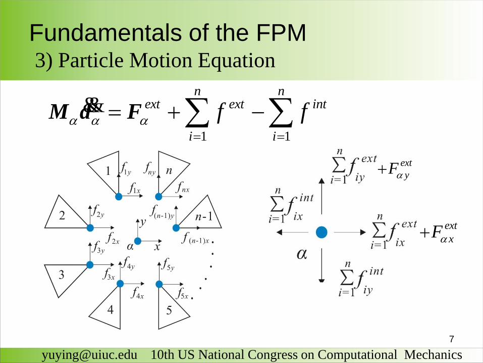
Fundamentals of the FPM3) Particle Motion Equation
1 1
n next ext int
i i
f f
M d F&&
ext
yF
ext
xF
8
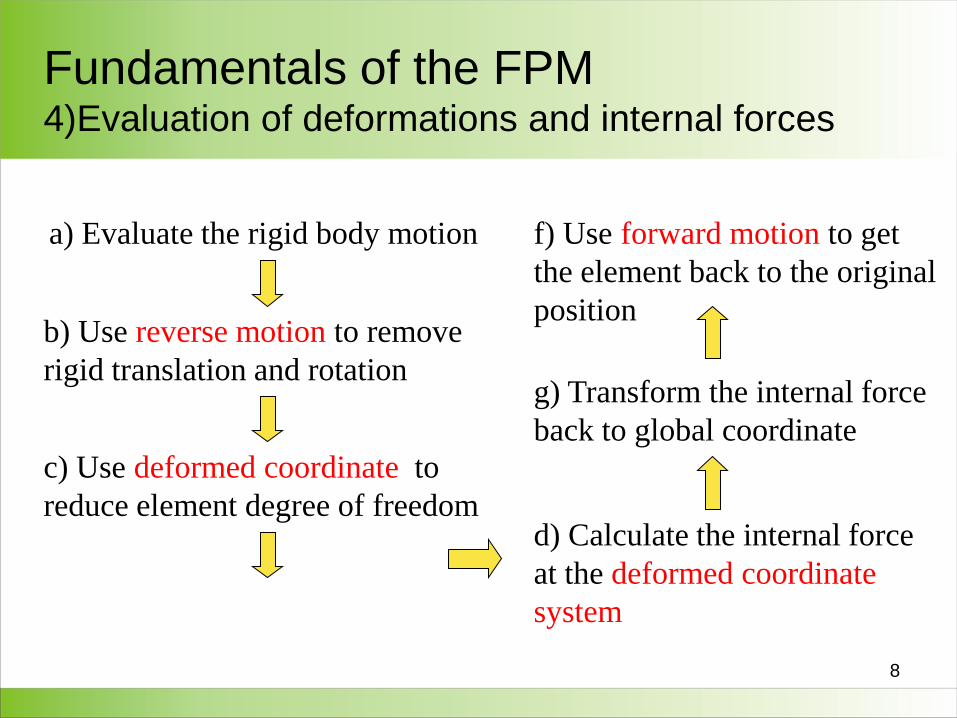
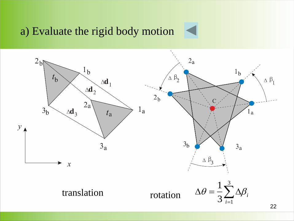
a) Evaluate the rigid body motion
b) Use reverse motion to remove
rigid translation and rotation
c) Use deformed coordinate to
reduce element degree of freedomd) Calculate the internal force
at the deformed coordinate
system
g) Transform the internal force
back to global coordinate
f) Use forward motion to get
the element back to the original
position
Fundamentals of the FPM4)Evaluation of deformations and internal forces
9
[email protected] 10th US National Congress on Computational Mechanics
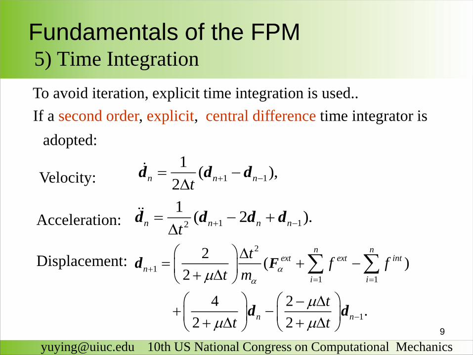
Fundamentals of the FPM5) Time Integration
To avoid iteration, explicit time integration is used..
If a second order, explicit, central difference time integrator is
adopted:
1 1
1( ),
2n n n
t
d d d
1 12
1( 2 ).n n n n
t
d d d d
2
1
1 1
1
2( )
2
4 2.
2 2
n next ext int
n
i i
n n
tf f
t m
t
t t
Fd
d d
Velocity:
Acceleration:
Displacement:
10
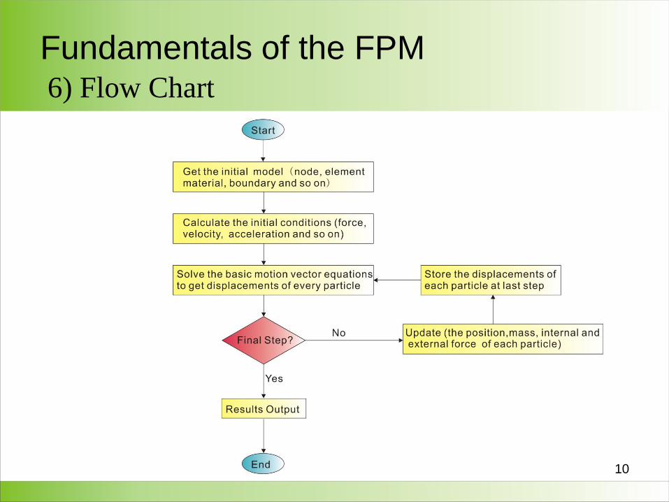
Fundamentals of the FPM6) Flow Chart
11
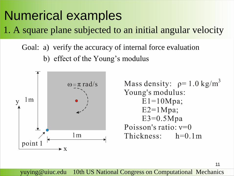
Goal: a) verify the accuracy of internal force evaluation
b) effect of the Young’s modulus
Numerical examples 1. A square plane subjected to an initial angular velocity
[email protected] 10th US National Congress on Computational Mechanics
12
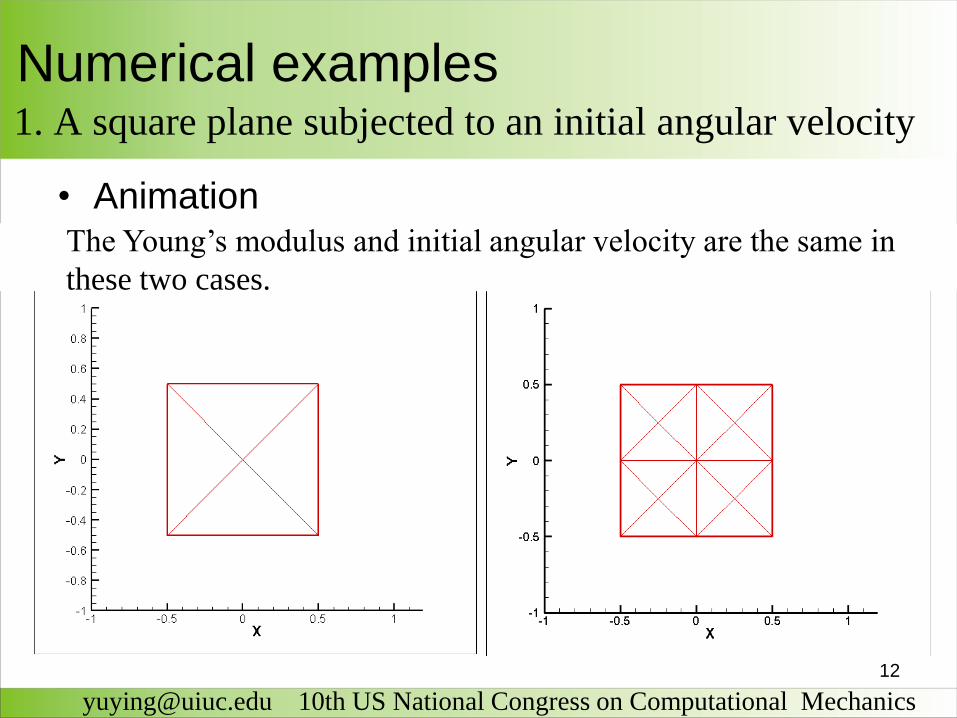
Numerical examples 1. A square plane subjected to an initial angular velocity
[email protected] 10th US National Congress on Computational Mechanics
• AnimationThe Young’s modulus and initial angular velocity are the same in
these two cases.
13
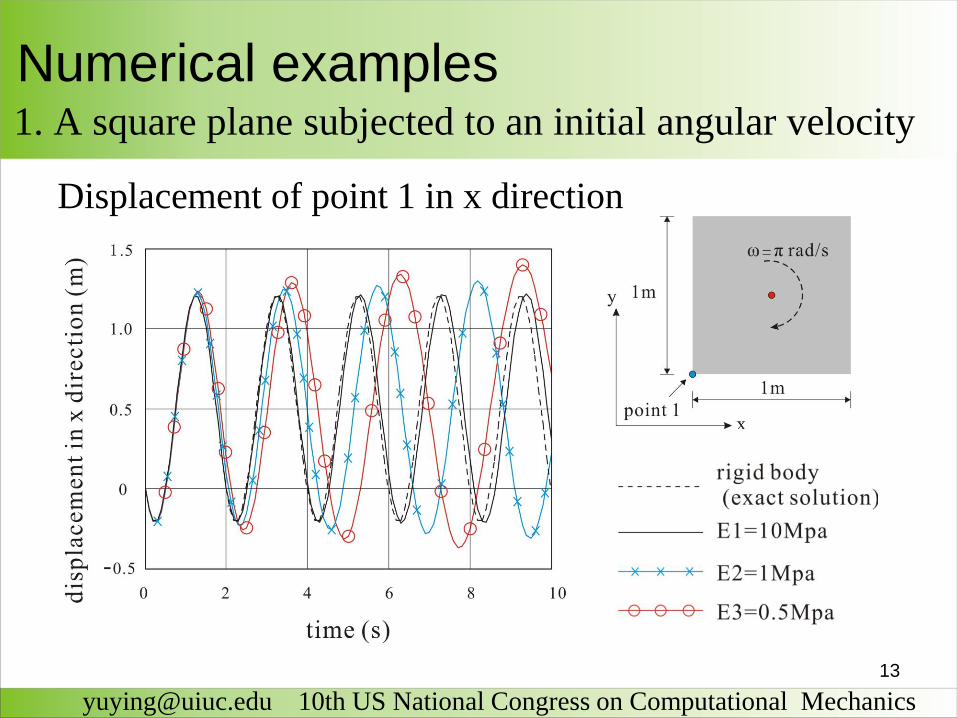
Displacement of point 1 in x direction
Numerical examples 1. A square plane subjected to an initial angular velocity
[email protected] 10th US National Congress on Computational Mechanics
14
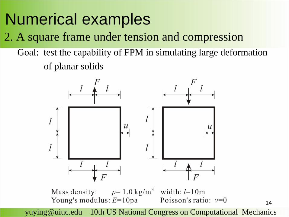
Numerical examples 2. A square frame under tension and compression
[email protected] 10th US National Congress on Computational Mechanics
Goal: test the capability of FPM in simulating large deformation
of planar solids
15
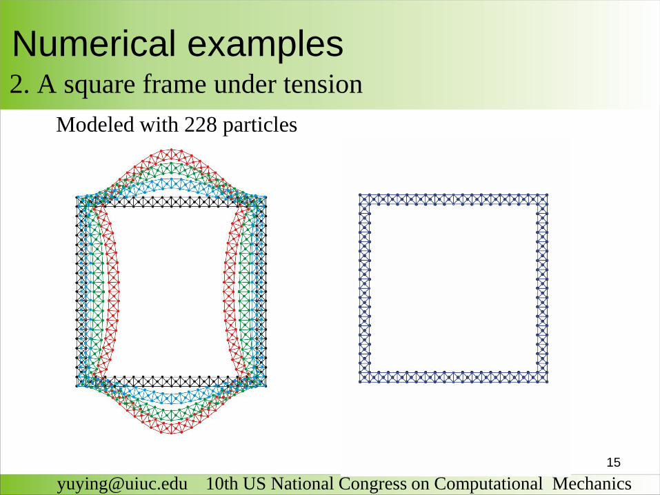
Numerical examples 2. A square frame under tension
[email protected] 10th US National Congress on Computational Mechanics
Modeled with 228 particles
16
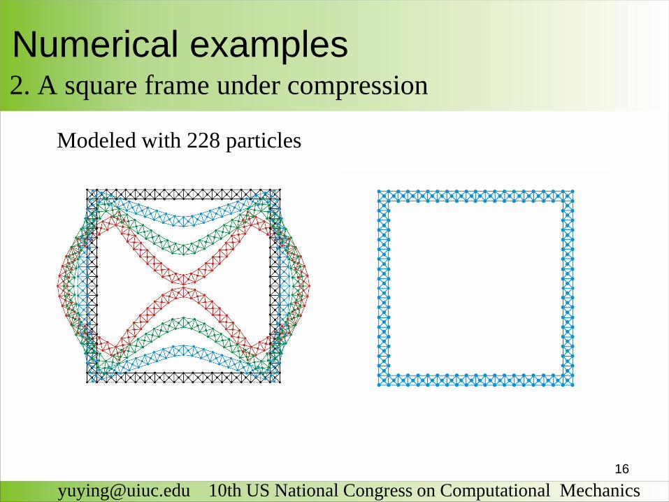
Numerical examples 2. A square frame under compression
[email protected] 10th US National Congress on Computational Mechanics
Modeled with 228 particles
17
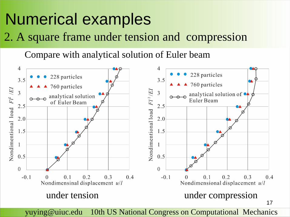
Numerical examples 2. A square frame under tension and compression
[email protected] 10th US National Congress on Computational Mechanics
under tension under compression
Compare with analytical solution of Euler beam
18
Remarks on the Finite Particle Method
[email protected] 10th US National Congress on Computational Mechanics
1. FPM is based on the combination of the vector mechanicsand numerical calculations. It enforces equilibrium on each particle.
2. No iterations are used to follow nonlinear laws, and no matrices are formed. The procedures are quite simple and robust.
3. The examples demonstrate performance and applicability of the proposed method on large deflection analysis of planar solids.
19
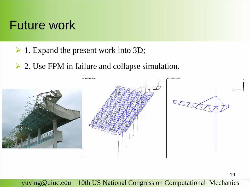
1. Expand the present work into 3D;
2. Use FPM in failure and collapse simulation.
Future work
[email protected] 10th US National Congress on Computational Mechanics
20
References
Ying Yu, Yaozhi Luo. Motion analysis of deployable
structures based on the rod hinge element by the finite particle
method. Proc. IMechE Part G: J. Aerospace Engineering.
2009, 223: 1-10.
Ying Yu, Yaozhi Luo. Finite particle method for kinematically
indeterminate bar assemblies. J Zhejiang Univ Sci A. 2009, 10
(5): 667-676.
Ying Yu, Glaucio Paulino, Yaozhi Luo. Finite particle method
for progressive failure simulation of framed structures .
(finished and will be submitted for publication )
22
a) Evaluate the rigid body motion
3
1
1
3i
i
translation rotation
23
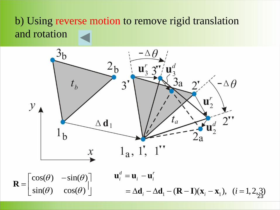
b) Using reverse motion to remove rigid translation
and rotation
1 1( )( ), ( 1,2,3)d d
u u u
R I x x
d r
i i i
i i i
cos( ) sin( )
sin( ) cos( )R
24
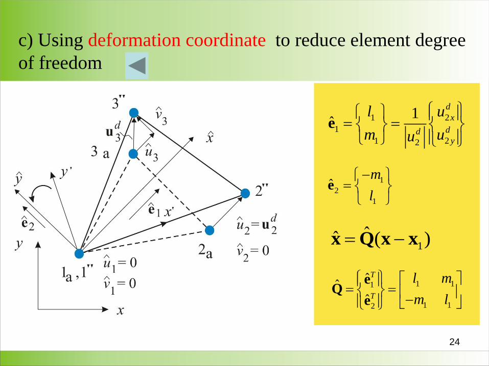
c) Using deformation coordinate to reduce element degree
of freedom
1 2
1
1 22
1ˆ
d
x
ddy
l u
m uu
e
1
2
1
ˆm
l
e
1ˆˆ ( )Q x xx
1 11
1 12
ˆˆ
ˆ
T
T
l m
m l
eQ
e
25
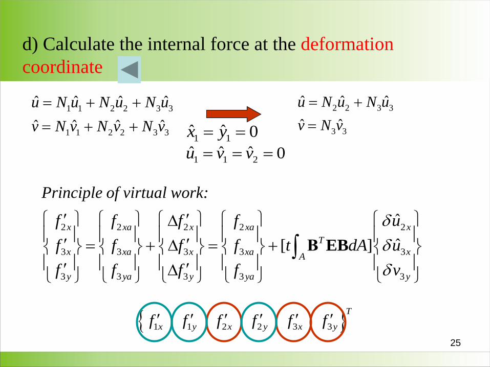
d) Calculate the internal force at the deformation
coordinate
1 1 2 2 3 3
1 1 2 2 3 3
ˆ ˆ ˆ ˆ
ˆ ˆ ˆ ˆ
u N u N u N u
v N v N v N v
2 2 3 3
3 3
ˆ ˆ ˆ
ˆ ˆ
u N u N u
v N v
1 1
ˆ ˆ 0x y
1 1 2ˆ ˆ ˆ 0u v v
1 1 2 2 3 3
T
x y x y x yf f f f f f
2 2 2 2 2
3 3 3 3 3
3 3 3 3 3
ˆ
ˆ[ ]Β EB
x xa x xa x
T
x xa x xa xA
y ya y ya y
f f f f u
f f f f t dA u
f f f f v
Principle of virtual work:
26
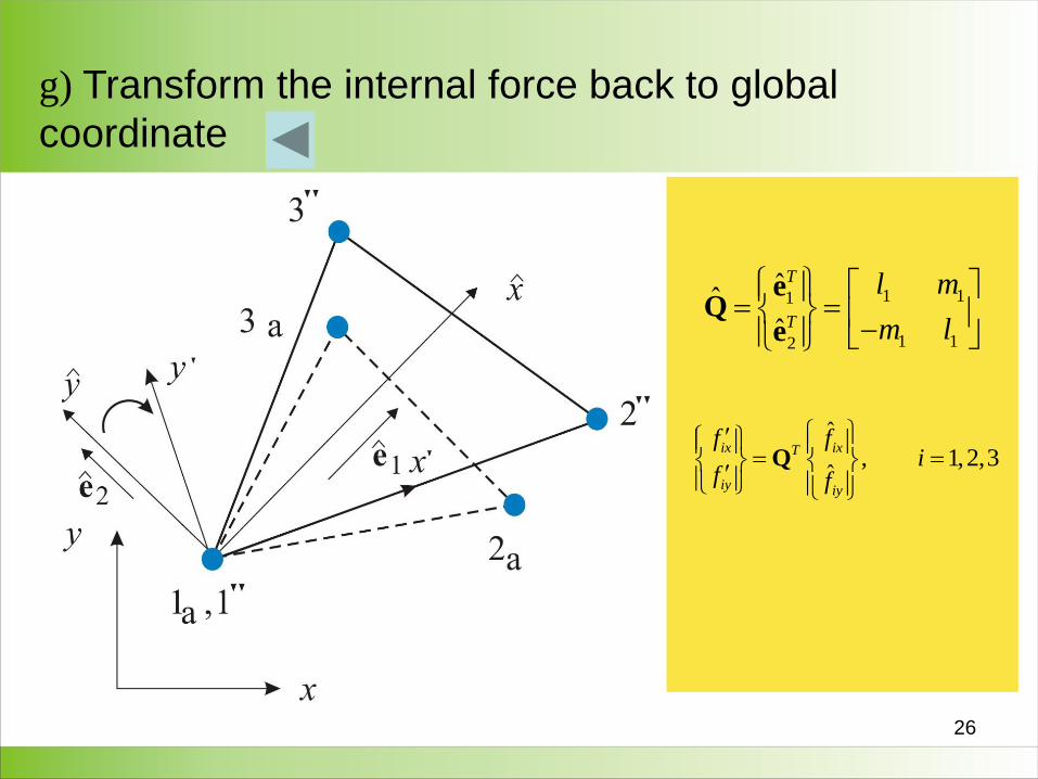
g) Transform the internal force back to global
coordinate
1 11
1 12
ˆˆ
ˆ
T
T
l m
m l
eQ
e
ˆ, 1,2,3
ˆQ
ix ixT
iy iy
f fi
f f
27
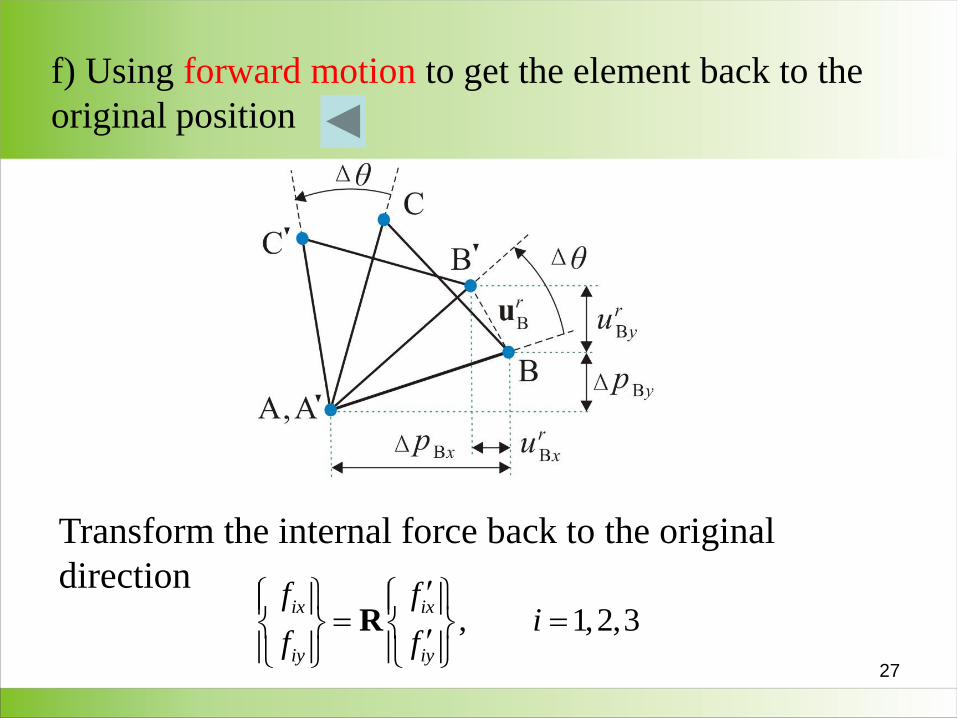
f) Using forward motion to get the element back to the
original position
Transform the internal force back to the original
direction
, 1,2,3Rix ix
iy iy
f fi
f f


![INDEX [kgr.ac.in]kgr.ac.in/beta/wp-content/uploads/2018/09/Mechanics-of-Solids-Lab-Manual.pdf · inversely proportional to flexural rigidity (EI). Actual deflection so calculated](https://img.pdfslide.us/doc/110x75/5e07383467c8f14dad195cf7/index-kgracinkgracinbetawp-contentuploads201809mechanics-of-solids-lab-.jpg)