Embed Size (px)
Citation preview

LAr Frontend Board PRR
Introduction
1. Overview of FEB functionality
2. FEB performance requirements
3. Development and evaluation of FEB
4. Organization of FEB PRR presentations and documents
John Parsons
Nevis Labs, Columbia University
March 18/2004
J. Parsons, FEB PRR, March 18/2004 2
functionality includes: receive input signals from calorimeter amplify and shape them store signals in analog form while awaiting L1 trigger digitize signals for triggered events transmit output data bit-serially over optical link off detector provide analog sums to L1 trigger sum tree
Frontend Board OverviewFrontend Board Overview

J. Parsons, FEB PRR, March 18/2004 3
read out 170k channels of calorimeter (total of 1524 FEBs) dynamic range 16 bits measure signals at bunch crossing frequency of 40 MHz (ie. every 25 ns) store signals during L1 trigger latency of up to 2.5 s (100 bunch crossings) digitize and read out 5 samples/channel at a max. L1 rate of 100 kHz
measure deposited energies with resolution < 0.25% coherent noise per channel < 5% of total noise per channel measure times of energy depositions with resolution << 25 ns
high density (128 channels per board) low power ( 0.8 W/channel) high reliability over expected lifetime of > 10 years must tolerate expected radiation levels (10 yrs LHC, no safety factors) of:
TID 5 kRad NIEL 1.6E12 n/cm2 (1 MeV eq.) SEU 7.7E11 h/cm2 (> 20 MeV)
Overview of Requirements of ATLAS LAr FEB

J. Parsons, FEB PRR, March 18/2004 4
Full functionality “Module 0” FEB boards were developed Provided verification of the electronics design concepts Used in testbeam runs with Module 0 and production calorimeter modules
In total, almost 50 Mod0 FEBs ( 6000 channels) were produced Have been operating reliably in testbeam for past several years (and continue to
do so) Performance meets or exceed ATLAS specifications
Due to schedule, Mod0 boards developed with some “short cuts”: Did not use final control signal (TTC and SPAC) distribution FEB used Cu output cables instead of optical links Did not pay strict attention to radiation tolerance requirements
the main task remaining in the development of the final ATLAS FEB was to radiation harden the designs, and in particular to replace several FPGAs and other COTs with custom rad-tol ICs
Module 0 Electronics Experience

J. Parsons, FEB PRR, March 18/2004 5 10 different custom rad-tol ASICs, relatively few COTs
Overview of main FEB components
32 SCA 16 ADC 8 GainSel
1 GLink1 Config.2 SCAC
1 SPAC
1 MUX32 Shaper
1 TTCRx7 CLKFO14 pos. Vregs+6 neg. Vregs
2 LSB
32 0T
128input
signals
1 fiber to RODAnalog
sumsto TBB
DMILL
DSM
AMS
COTS
2 DCU
TTC,SPACsignals
J. Parsons, FEB PRR, March 18/2004 6
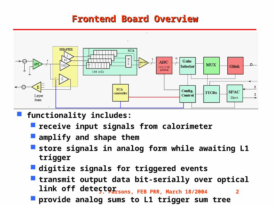
one GLink output link per FEB, with rate of 1.6 Gbps link collaboration includes SMU, ISN,
Stockholm, and Taiwan
FEB Optical Links
1.6 Gb/s
J. Parsons, FEB PRR, March 18/2004 7
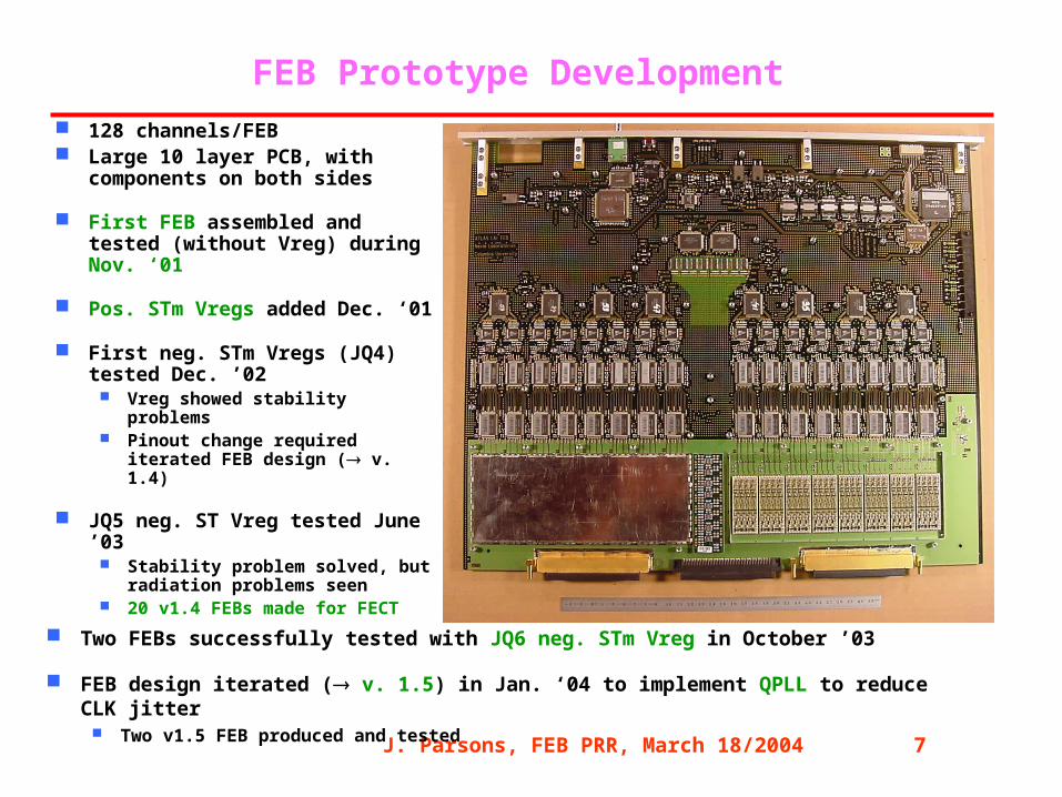
FEB Prototype Development
128 channels/FEB Large 10 layer PCB, with
components on both sides
First FEB assembled and tested (without Vreg) during Nov. ‘01
Pos. STm Vregs added Dec. ‘01
First neg. STm Vregs (JQ4) tested Dec. ’02
Vreg showed stability problems Pinout change required iterated
FEB design ( v. 1.4)
JQ5 neg. ST Vreg tested June ’03 Stability problem solved, but
radiation problems seen 20 v1.4 FEBs made for FECT
Two FEBs successfully tested with JQ6 neg. STm Vreg in October ’03
FEB design iterated ( v. 1.5) in Jan. ‘04 to implement QPLL to reduce CLK jitter Two v1.5 FEB produced and tested
J. Parsons, FEB PRR, March 18/2004 8
Before proceeding to PRRs of FE crate electronics, LAr decided to perform system test (at BNL) with all boards required for one half-FEC (~ 1% of total system) The FEC system test included 14 FEBs (1792 channels)
The main FEB results from FECT will be presented by Ioannis Katsanos
Last fall, it was observed during the FEC test that some of the FEBs showed large error rates in their output data optical links
Many detailed investigations since then have allowed us to understand that the problem was from jitter on the FEB CLK, due both to jitter in the incoming TTC signal and to jitter from the on-board TTCRx Usage of a “cleaner” TTC source allowed stable running of the FECT We have in addition modified the FEB design to incorporate the QPLL, in
order to provide more operating margin
Stefan Simion will summarize the jitter studies, and solution implemented
Front End Crate System Test

J. Parsons, FEB PRR, March 18/2004 9
1. Concern over availability of rad-tol negative Vreg JQ6 version from STm accepted for production Meeting (this week) to hear results of STm’s 1000 hr lifetime test Production quantity to be available next month
2. Concern over availability of ADC (joint order with CMS/LHCb) Delivery is well underway (2 lots accepted, 3rd lot being irradiated now)
3. Concern over SMUX/GLink timing issues for optical link Delay chip added to provide additional margin Most important timing parameters being measured for each SMUX chip
4. Proposed use of Power-on-Reset scheme as per the CALIB board Done
5. Diodes should be tested for radiation tolerance Done for pre-selection, planned for production (see Stefan’s talk)
6. Develop further plan for traceability of components via serial numbers1. Done
Issues from FEB Final Design Review (June 18/02)

J. Parsons, FEB PRR, March 18/2004 10
FEB results from FEC system test - Ioannis Katsanos
Timing/jitter studies - Stefan Simion
Summary of FEB radiation qualification - Stefan Simion
FEB production and QA/QC overview - John Parsons
FEB HASS test - Gustaaf Brooijmans
FEB test setup at LAL - Dirk Zerwas
FEB test setup at BNL - Hucheng Chen
Summary - John Parsons
FEB PRR Presentations