Embed Size (px)
Citation preview

California Integrated Waste Management Board
May 2008
California Environmental Protection Agency
Landfill Gas Monitoring Well Functionality at 20 California Landfills
Produced Under Contract by:
Contractor’s Report
To The Board
SCS Engineers

Contractor’s Report to the Board ii
Disclaimer: This report to the Board was produced under contract by SCS Engineers. The
statements and conclusions contained in this report are those of the contractor and not
necessarily those of the California Integrated Waste Management Board, its employees, or the
State of California and should not be cited or quoted as official Board policy or direction.
The State makes no warranty, expressed or implied, and assumes no liability for the information
contained in the succeeding text. Any mention of commercial products or processes shall not be
construed as an endorsement of such products or processes.
S T A T E O F C A L I F O R N I A
Arnold Schwarzenegger
Governor
Linda S. Adams
Secretary, California Environmental Protection Agency
INTEGRATED WASTE MANAGEMENT BOARD
Margo Reid Brown
Board Chair
Cheryl Peace
Board Member
Wesley Chesbro
Board Member
Gary Petersen
Board Member
Rosalie Mulé
Board Member
Vacant Position Board Member
Mark Leary
Executive Director
For additional copies of this publication, contact:
Integrated Waste Management Board Public Affairs Office, Publications Clearinghouse (MS–6)
1001 I Street P.O. Box 4025
Sacramento, CA 95812-4025 www.ciwmb.ca.gov/Publications/
1-800-CA-WASTE (California only) or (916) 341-6300
Publication #IMWB-2008-022
Copies of this document originally provided by CIWMB were printed on recycled paper containing 100 percent postconsumer fiber.
Copyright © 2008 by the California Integrated Waste Management Board. All rights reserved. This publication, or parts thereof, may not be reproduced in any form without permission.
Prepared as part of contract number IWM-05012 for $153,626.
The California Integrated Waste Management Board (CIWMB) does not discriminate on the basis of disability in access to its programs. CIWMB publications are available in accessible formats upon request
by calling the Public Affairs Office at (916) 341-6300. Persons with hearing impairments can reach the CIWMB through the California Relay Service, 1-800-735-2929.

Contractor’s Report to the Board ii
This report, titled Landfill Gas Monitoring Well Functionality at 20 California Landfills, was
prepared and reviewed by the following:
Raymond H. Huff, R.E.A.
Senior Project Manager
SCS ENGINEERS
John Bell
Contract Manager
CALIFORNIA INTEGRATED WASTE MANAGEMENT BOARD
Mark B. Beizer, P.E.
Project Director
SCS ENGINEERS

Contractor’s Report to the Board i
Table of Contents Table of Contents ........................................................................................................................................... i
Executive Summary ...................................................................................................................................... 1
Introduction ................................................................................................................................................... 2
Project Objectives and Approach .................................................................................................................. 2
Probe Functionality Assessment ................................................................................................................... 3
Pre-Assessment Activities ...................................................................................................................... 3
Initial Monitoring Probe Condition Assessment .................................................................................... 3
Gas Monitoring Assessment ................................................................................................................... 6
Vacuum Testing ................................................................................................................................... 11
Video Borescope Inspection ................................................................................................................. 12
Lithology Evaluation ............................................................................................................................ 16
Probe Functionality Determination ............................................................................................................. 17
Non-Functional Probes ......................................................................................................................... 17
Probes of Indeterminate Functionality ................................................................................................. 20
Conclusions and Recommendations ........................................................................................................... 21
Conclusions .......................................................................................................................................... 21
Statewide Probe Functionality .............................................................................................................. 22
Recommendations ................................................................................................................................ 23
Appendix A—Contractor’s Work Plan …………………………………………………………………...24
Appendix B—Probe Functionality Investigation Summary and Determination ……………………….. .. 46

Contractor’s Report to the Board 1
Executive Summary The intent of the study is to evaluate the functionality of landfill gas (LFG) perimeter migration
monitoring probes; in other words, that the monitoring data collected is representative of the
actual soil gas conditions in the vicinity of the screened portion of each probe.
CIWMB preselected 20 landfill sites in northern and southern California to be included in this
study. The landfills were selected to include a variety of landfill sizes, geomorphic and geologic
settings, and the presence of relatively deep gas probes (40 to 99 feet, or more). Ten probes at
each landfill were selected by the contract manager for functionality review and determination.
For purposes of this report, we refer to each drilled hole as a well and each individually installed
section of PVC as a probe. This report details the on-site activities associated with the
functionality assessment and discusses the combined results as they relate to a determination of
the overall functionality of each probe at each of the 20 landfill sites.
In order to implement the Functionality Study, a standardized approach to probe functionality
assessment was developed prior to implementation of the field portion of the Functionality Study.
The standardized approach for probe assessment consisted of the following activities:
Pre-Assessment Activities, which consisted of pre-notification of site owners/operators, on-
site random selection of probes, and recording of ambient conditions (pressure, weather, etc.).
Initial Condition Assessment, which consisted of reviewing the geographic location of the
probe, reviewing the identification methodology for the probe, assessing the probehead
assembly (fittings, piping, etc.), and conducting surface emissions monitoring in the vicinity
of the probe.
Gas Monitoring Assessment, which consisted of recording initial pressure readings, LFG
monitoring, ambient oxygen analysis, depth trend analysis, and methane concentration
analysis.
Vacuum Testing of the probe, which consisted the application of a known vacuum to a probe
and recording the probe response once the vacuum was stopped.
Video Borescope Inspection, which consisted of verifying the probe construction by
creating a video log of the inside of the probe using a small diameter borescope.
Lithology Evaluation, which consisted of the evaluation of the adequacy of the placement of
the screened section of a probe considering permeable and porous lithologies.
As discussed in the report, there is no single way in which to evaluate the functionality of a probe.
It is through a combination of observations that probe functionality can be determined. For each
probe evaluated under this study, SCS reviewed the results from the various components of the
sampling program and made a determination as to the probe’s functionality for compliance
monitoring purposes. The results of this assessment are provided in Table 2 (Appendix B).
As shown in Table 2, there were a total of 61 probes identified as non-functional, 12 probes
identified as “indeterminate,” and 117 probes identified as functional.
Based upon this study, the current approach to LFG perimeter migration monitoring probe design,
construction, and installation is unsatisfactory. An industry/regulatory standard should be set for
probe construction and installation.

Contractor’s Report to the Board 2
Introduction SCS Engineers (SCS) is pleased to submit this report to the California Integrated Waste
Management Board (CIWMB) on the study of existing landfill gas (LFG) perimeter migration
monitoring wells (probes) located at various landfills throughout the State. For purposes of this
report, we refer to each drilled hole as a well and each individually installed section of PVC as a
probe. Therefore, a typical perimeter migration monitoring well will consist of two or more
nested probes.
The intent of the study is to determine the functionality of perimeter migration monitoring probes;
that is to say, that the monitoring data collected is representative of the actual soil gas conditions
in the vicinity of the screened portion of each probe.
Ten probes at each landfill were selected randomly for functionality review and determination.
This report details the on-site activities associated with the functionality assessment and discusses
the combined results as they relate to a determination of the overall functionality of each probe at
each of the 20 landfill sites.
Because a significant number of gas monitoring probes were determined to be non-functional for
purposes of LFG migration monitoring and assessment, it would tend to indicate that landfill gas
migrations may be underestimated or undetected at a larger number of California sites, potentially
leading to dangerous conditions for people and facilities located near landfills and adverse effects
on the environment. Therefore, based on the results and conclusions drawn from this study,
existing regulations may need to be enhanced to ensure that monitoring probes installed around
landfills are functional and capable of detecting migrating LFG in accordance with the California
Code of Regulations (CCR) Title 27, §20919.5.
The assessment of landfill gas monitoring well functionality that has been completed under this
study focused on visual and physical testing of 190 landfill gas probes located at 20 sites in
California.* All monitoring and testing has been conducted in accordance with the methods in the
approved work plan dated November 2006, which is included as Appendix A.
Project Objectives and Approach CIWMB selected 20 landfill sites in northern and southern California to be included in this study.
The landfills were selected to include a variety of landfill sizes, geomorphic and geologic
settings, and the presence of relatively deep gas probes (40-99 feet). These deeper probes have
the greatest potential for installation problems, ground water infiltration, or other conditions that
could render them ineffective monitoring points. Table 1 (listed in Appendix A) presents a listing
of the landfills included in the study.
SCS reviewed internal files regarding the sites selected by CIWMB to determine if landfill gas
probe information existed for these sites in the SCS files.
* A total of 200 probes (10 at each site) were evaluated; however, 10 probes were deemed to be non-
applicable for this study due to probe construction (e.g., assembled with screws) or probe depth beyond
the study’s equipment limitations.

Contractor’s Report to the Board 3
Data of concern included:
Locations of probes
Construction details and as-built diagrams
Completion depths
Gas monitoring history
Well boring logs
After obtaining as much data as possible from the SCS files, a data request was made to CIWMB
for missing data. This included those sites for which SCS did not have any data, or for portions of
data not in our files.
The actual probes to be investigated at each landfill were selected by CIWMB staff, at each site,
on the day or days of each site study.
Probe Functionality Assessment SCS developed a standardized approach to the review and assessment of each of the 20 landfill
sites located throughout the State, working in concert with CIWMB. The project was broken into
northern and southern regions, with 10 landfill sites located within each region. Our general
approach to data collection at each site, along with a narrative of our findings is presented below.
Pre-Assessment Activities
Pre-Notification and On-Site Arrival
Prior to the planned arrival date for each landfill, CIWMB personnel contacted the landfill
operator to coordinate on-site activities. In some cases, the owner/operator wished to have a
representative present during the probe study, so arrangements were made to accommodate this
representative.
Selection of Gas Probes
Upon arrival at each landfill, CIWMB staff selected the probes to be investigated after meeting
with on-site officials and considering the age, depth, and accessibility of the probes.
Ambient Conditions
At each landfill site, prior to the assessment of each LFG migration monitoring well, SCS
recorded ambient atmospheric conditions including weather, barometric pressure, temperature,
wind speed, and wind direction.
Recordkeeping
All data collected for each probe investigation was recorded on a Landfill Gas Probe Field Data
Sheet. A copy of the completed data sheets for each probe at each site is located in Appendix B.
Initial Monitoring Probe Condition Assessment
For each of the 20 sites included in the study, SCS performed an assessment of the initial
monitoring probe conditions, consisting of an evaluation of probe location, probe identification,
and probehead assembly assessment, as well as performing an assessment of surface emissions
around each probe. A summary of probe-by-probe findings for the initial monitoring conditions is
included as Table 2 (Appendix B). The results of this initial assessment are discussed below.
Contractor’s Report to the Board 4
Monitoring Probe Location
For each site, SCS was provided with a map of the landfill to locate the probes to be monitored.
When the mapped location of a probe was verified in the field, SCS cross-checked the map to
determine if the map properly identified the true location of the probe. SCS then digitally
photographed the gas probe wellhead and surrounding area. A photograph or video identification
(picture number, etc.) has also been recorded on the Landfill Gas Probe Field Data Sheets
(Appendix B). Of all of the probes selected for this study, only one probe (probe GP-5B at the
City of Huntington Beach Landfill) was not properly located on the map.
Monitoring Probe Identification
In order to properly identify monitoring probes at a landfill, the probe should be uniquely labeled
in order to distinguish it from other probes within the casing. This is typically done by
sequentially numbering the well locations around the site and using a designation of “S” for
shallow depth, “M” for medium depth, and “D” for deep depth probes (for triple-nested probes).
In some cases this was done adequately, but during the study several inconsistencies were found
which made it difficult to determine the identity of the monitoring probe. A summary of
inconsistencies identified at each site is presented in Table 2 (Appendix B).
While some of the landfill sites used alternative designations that were relatively easy to interpret,
as in the example of probe G-3A (shallow) and G-3B (mid-depth) at Ukiah Landfill, not all were
so clear. For example, all ten probes at the City of Huntington Beach Landfill were identified
using a depth designation of “Y,” “B,” and “R,” representing shallow, mid-depth, and deep
probes respectively (as determined using video borescope records).
In some cases, it was apparent that probe well boxes had been exposed to the elements for some
time, and any identification markings (mostly permanent marker) had worn off. SCS found that
this problem was not particularly difficult to solve given a functional probe location map for the
site.
However, in some cases, probes were mislabeled. For example, at Clovis Landfill, the probe
labeled MMW-108M was determined to be the deep probe after the video borescope investigation
(see Section 3.5). The probe labeled MMW-108D was actually the mid-depth probe. At Corral
Hollow Landfill, the probe labeled GW-1S was actually the deep probe.
Based on observed probes, SCS recommends that each probe should be individually labeled with
the well identification, as well as probe relative depth (shallow, mid-depth, and deep), and
screened interval (i.e., MP-1; S; 7-10’, for a shallow probe, screened from 7 to 10 feet below
ground surface[bgs]).
Probehead Assembly Assessment
All of the landfills monitored at the time of this study had some type of probe surface
configuration which included a gas monitoring port used to periodically sample gas
concentrations. Table 2 (Appendix B) contains construction details (including wellhead
assembly) for probes at each landfill monitored in this study.
The probehead design assembly encountered during the study tended to vary significantly from
site-to-site, and sometimes even from well to well on a single site. For most of the probes
included in this study, the gas monitoring port was adequate enough to take sample readings from
the probe. However, there were some cases in which proper readings could not be obtained from
the probe due to improper monitoring port assembly and/or design.

Contractor’s Report to the Board 5
For example, some of the monitoring probes at Clovis, Buena Vista, and Crazy Horse landfills
had wellhead assemblies that were not adequate to take samples with the instruments that were
used in this study. In order to take gas concentration readings and conduct the vacuum test on
these monitoring probes, the existing probehead had to be taken off and another probehead was
put on. Because the probehead was removed, initial pressure in the probe could not be obtained.
(Note: Each probe that had to have the probehead replaced was given approximately five minutes
to regain the static pressure that existed before the probehead was removed.)
The gas monitoring port of the probes at each landfill also varied. Table 2 (Appendix B) describes
the type of cap (slip cap, threaded cap, rubber stopper, etc.) used for the valve assembly. Some
port types (e.g., labcock vales and quick-connect fittings) were more conducive to valid sample
collection (ability to measure static pressure in an enclosed probe, etc.), whereas other port types
(e.g., bicycle valve stem, slip cap, threaded caps, rubber stoppers, open pipe, etc.) are not.
Based on observed probes, SCS has found that labcock valves and/or quick connect fittings
provided the best connection for standard monitoring instruments.
Surface Emissions Monitoring
At each site, surface emissions monitoring (SEM) was conducted in order to assess the overall
integrity of the wellhead and individual probe completions; in other words, surface emissions
may be an indicator that subsurface gases are migrating up the well borehole, outside of the probe
casing. SEM activities were conducted within a five-foot radius around each monitoring well
using an RKI Eagle, calibrated to read combustible gases as methane. SEM was conducted in
order to evaluate the potential for the presence of LFG due to possible inadequate probe design or
probe breakage. The results of the surface emissions monitoring are included in Table 2
(Appendix B). Note that in addition to the SEM data, the inside of each well box was also
monitored. (The results, if any, from this additional monitoring are included in the comments
column of the initial monitoring section of Table 2.)
Generally, it appears that wellhead design of the monitoring probes at each landfill prevented
escaping gases from entering the atmosphere. As shown in Table 2, surface emissions were
detected at the following sites around the following wells:
Ukiah Landfill (2 out of 4 wells; G-3 and GAS-6)
Anderson Landfill (2 out of 5 wells; GM-6 and GM-7)
Benton/Redding Landfill (3 out of 6 wells; GM-1, GM-2A, and GM-4A)
Crazy Horse Landfill (1 out of 5 wells; GW-1D)
Hillside Landfill (1 out of 6 wells; P-18)
Kiefer Road Landfill (1 out of 7 wells; GP-44)
Red Bluff Landfill (4 out of 6 wells; GW-3, GW-2, GW-4, and GW-7D)
The highest SEM concentrations identified were at the Crazy Horse Landfill, associated with the
well box assessment of GW-1. During this assessment, methane concentrations within the well
box for GW-1 were 10 percent by volume, which is within the explosive range for methane.
Likely causes of significant gas detections near the ground surface outside of the probe casing
may include:
Inadequate probe completions (deteriorated bentonite seals, etc.)
Cracks, leaks in probe casing near ground surface
Poorly designed/opened sample ports at the time of monitoring

Contractor’s Report to the Board 6
Improper design of the wellhead assembly
Location of probe in proximity to refuse footprint
Gas Monitoring Assessment
Initial Pressure Readings
Following initial condition assessment, SCS monitored each probe for initial pressure using a
magnahelic or Dwyer electronic pressure gauge. This data provides an initial assessment of the
subsurface environment of the probe, and can also be used to assist in determination of probe
functionality. While a positive pressure reading in a probe is generally considered indicative of
gas generation and migration away from the refuse mass, a negative pressure reading is generally
indicative of a probe under vacuum, as may be seen with probes located in close proximity to an
LFG extraction well. Note that this assertion is made notwithstanding the influence of typical
(e.g., diurnal) barometric pressure fluctuations within probes. However, and more importantly,
the more of a variation from ambient (zero) static pressure a probe displays, the more a probe can
be relied upon as functional since, by showing either negative or positive pressure, the probe is
also demonstrating that it can hold pressure.
As shown in Table 2 (Appendix B), 59.5 percent (113 out of the 190 probes monitored) had a
zero pressure reading. As noted above, an initial pressure reading of zero does not indicate that
the probe is non-functional.
LFG Monitoring
In addition to ambient pressure and temperature, SCS monitored each probe for methane (CH4),
carbon dioxide (CO2), and oxygen (O2), using a Landtech Gas Extraction Monitor (GEM 2000).
Probes were also monitored for carbon monoxide (CO) and hydrogen sulfide (H2S) using an RKI
Eagle multi-gas meter. For this study, readings were monitored until a steady state level was
achieved for 30 seconds, where possible. Gas concentrations observed were recorded on the
Landfill Gas Probe Field Data Sheet (Table 2--Appendix B).
Gas concentrations monitored from each probe should represent the concentration of gases in the
soils around the screened portion of the probe. In order for gas concentration data to validate the
functionality of a given probe, the concentrations of gases observed in the probe itself must be
indicative of a subsurface environment (e.g., lower than ambient O2, increased CO2, etc.).
Ambient Oxygen Analysis
Gas concentrations within shallow probes that are not influenced by migrating LFG generally
have a higher (closer to ambient) concentration of oxygen than do deeper probes. This is because
air exchange with the atmosphere, under barometric influences, decreases substantially as you go
deeper into the soil horizons, while natural (non-landfill) subsurface oxidation and decay of soil
organics (roots, etc) increases. Further, migrating methane itself can be biologically oxidized
within soil pore spaces.
Aerobic microorganisms in soils deplete the oxygen and release carbon dioxide within the soil,
resulting in higher concentrations of carbon dioxide and lower concentrations of oxygen. This is
especially common in the deep probes where oxygen concentrations are expected to be low.
Therefore, a decrease in oxygen with depth in probe monitoring is typically considered to be
indicative of a valid sample obtained from a subsurface environment, whereas near atmospheric
levels of oxygen in a deep probe, while they can and do periodically occur, is generally indicative

Contractor’s Report to the Board 7
of atmosphere leaking into a probe via a crack in the casing, a break in the sampling
port/sampling train, or a leak in sampling valve itself.
Of the 190 probes monitored for this study, 19.5 percent (37) had ambient levels (at or greater
than 20 percent oxygen by volume) in the probe at the time of monitoring. A site-by-site
summary of these probes is presented below.
Ukiah Landfill – 1 probe
GAS-9M Probe screened* from 16 to 19 feet bgs.
Anderson Landfill – 3 probes
GM-2D Probe screened* from 85 to 89 feet bgs.
GM-6D Probe screened* from 67 to 75 feet bgs.
GM-11IS Probe screened* from 39 to 45 feet bgs.
Benton/Redding Landfill – 2 probes
GM-2A-Deep Probe screened* from 22 to 30 feet bgs.
GM-4A-Deep Probe screened* from 53 to 63 feet bgs.
Buena Vista Landfill – 4 probes
GP-12M Probe screened Work on symposium handouts (per borescope review)
from 38 to 43 feet bgs.
GP-11D Probe screened* at undetermined depth greater than 40 feet bgs.
GP-15M Probe screened (per borescope review) from 37 to 53 feet bgs.
GP-15D Probe screened (per borescope review) from 63 to 83 feet bgs.
Crazy Horse Landfill – 1 probe
GW-7M Probe screened (per borescope review) from 37 to 47 feet bgs.
Azusa Landfill – 1 probe
NP1_A Probe screened* from 51 to 56 feet bgs.
Bradley Landfill – 1 probe
W-2B Probe screened* from 43 to 65 feet bgs.
Coyote Canyon Landfill – 6 probes
P-45 L3 Probe screened* from 48 to 66 feet bgs.
P-48 L3 Probe screened from 46 to 61 feet bgs.
P-48 L4 Probe screened from 70 to 75 feet bgs.
P-57 L3 Probe screened* from 55 to 70 feet bgs.
P-61 L3 Probe screened* from 47 to 64 feet bgs.
P-61 L4 Probe screened* from 72 to 89 feet bgs.
City of Huntington Beach Landfill – 1 probe
GP-2B Probe screened* from 30 to 50 feet bgs.
Milliken Landfill – 1 probe
MPG-51S Probe screened (per borescope review) from 10 to 28 feet bgs.
Olinda Alpha Landfill – 4 probes
MP-6A_1 Probe screened* from 9 to 44 feet bgs.
MP-5_2 Probe screened* from 21 to 39 feet bgs.
MP-5_3 Probe screened from 47 to 79 feet bgs.

Contractor’s Report to the Board 8
MP-4_1 Probe screened* from 56 to 99 feet bgs.
Otay Landfill – 10 probes
GP-16 M Probe screened* from 17 to 28 feet bgs.
GP-16 D Probe screened* from 35 to 50 feet bgs.
GP-19 M Probe screened* from 17 to 88 feet bgs.
GP-19 D Probe screened* from 95 to 170 feet bgs.
GP-9 M Probe screened* from 17 to 51 feet bgs.
GP-9 D Probe screened* from 53 to 96 feet bgs.
GP-7 M Probe screened* from 17 to 48 feet bgs.
GP-7 D Probe screened* from 55 to 91 feet bgs.
GP-1 M Probe screened* from 17 to 42 feet bgs.
GP-1 D Probe screened* from 49 to 75 feet bgs.
South Chollas Landfill – 2 probes
SC-18 D Probe screened* from 20 to 30 feet bgs.
SC-19 D Probe screened* from 20 to 30 feet bgs.
* Indicates data obtained from installation records for probe.
With the possible exception of the Otay Landfill†, the 37 probes listed above are considered
suspect due to the presence of ambient oxygen in the probe. These probes are considered
“suspect” since only one of the several evaluation factors used in this study failed. Note that
additional evaluation (see other sections) is necessary prior to the determination that these probes
are non-functional.
Depth Trend Analysis
As part of the evaluation of gas data, where available, SCS also reviewed shallow to deep gas
trends, particularly CO2 and O2 between shallower and deeper probes within the same well in
order to further evaluate the validity of the gas monitoring data. Out of a total of 75 wells in the
study with at least one shallow and one deeper probe, 39 of the wells had a decreasing oxygen
(and increasing CO2) trend with depth, whereas 20 of the wells had increasing oxygen trends with
depth. The remaining 16 wells either had little to no change in oxygen concentrations between
probes, or were triple nested, and had mixed trend results. The 21 wells identified with an
increase of oxygen with depth are listed on a site-by-site basis and are discussed in more detail
below.
† The ambient readings from the Otay Landfill are considered a possible exception since all probes from
this site showed ambient oxygen levels, at all depths, which indicates that site lithology may play a
significant role in atmospheric intrusion.
Contractor’s Report to the Board 9
Anderson Landfill – 3 wells
GM-1 This well had an increase in O2 between the mid-depth and deep probe (0
percent to 14.7 percent). This is likely due to the decrease in methane
between the two probes (17.3 percent to 6.4 percent, respectively) and is
thus should still be considered as a functional well.
GM-2 This well had an increase in O2 between the mid-depth and deep probe (0
percent to 20.2 percent). Similar to GM-1, this well also shows a
significant decrease in methane between the mid-depth and deep probes
(53.3 percent to 0 percent). In addition, CO2 dropped from 37.6 to 0
percent . This drop, combined with the ambient O2 levels identified in a
deeper probe, is suspect.
GM-6 This well had an increase in O2 between the mid-depth and deep probe
(17.6 percent to 20.2 percent). Similar to GM-2, CO2 levels in this well
went from 1.6 percent down to 0 percent. This drop, combined with the
ambient O2 levels identified in a deeper probe, is suspect.
Benton/Redding Landfill – 2 wells
GM-2A This well had an increase in O2 between the mid-depth and deep probe
(18.8 percent to 20.0 percent), as well as a drop in CO2 (1.4 percent to 0
percent). This drop, combined with the ambient O2 levels identified in a
deeper probe, is suspect.
GM-4A This well had an increase in O2 between the mid-depth and deep probe
(18.1 percent to 20.0 percent), as well as a drop in CO2 (0.6 percent to 0
percent). This drop, combined with the ambient O2 levels identified in a
deeper probe, is suspect.
Buena Vista Landfill – 1 well
GP-11 This well had an increase in O2 between the shallow and deep probe (19.7
percent to 20.3 percent), as well as a drop in CO2 (1.2 percent to 0 percent).
This drop, combined with the ambient O2 levels identified in a significantly
deeper probe, is suspect.
Clovis Landfill – 3 wells
MMW-112 This well had an increase in O2 between the 55-foot deep and 65 foot deep
probe (5.9 percent to 19.4 percent), as well as a drop in CO2 (21.6 percent
to 0 percent). This drop, combined with the near-ambient O2 levels
identified in a similar depth probe, is suspect.
MMW-116 This well had an increase in O2 between the mid-depth and deep probe
(19.5 percent to 19.9 percent). Note there was no CO2 detected in either
probe. The increase in O2 with depth could easily be attributable to
instrument read error due to the closeness of the readings. Therefore, these
probes may still be considered functional.
MMW-122 This well had an increase in O2 between the mid-depth and deep probe (4.7
percent to 18.0 percent), as well as a drop in CO2 (21.9 percent to 2.5
percent). This drop, combined with the increase in O2 levels identified,
while generally considered suspect, may still be indicative of a subsurface
environment. Therefore, these probes may still be considered functional.

Contractor’s Report to the Board 10
Corral Hollow Landfill – 2 wells
GW-3 This well had an increase in O2 between the mid-depth and deep probe
(17.5 percent to 18.4 percent), as well as a drop in CO2 (3.9 percent to 2.6
percent). This drop, combined with the increase in O2 levels identified,
while generally considered suspect, may still be indicative of a subsurface
environment. Therefore, these probes may still be considered functional.
GW-4 This well had an increase in O2 between the mid-depth and deep probe
(17.5 percent to 19.5 percent), with no CO2 detected in either probe. This
increase in O2 levels identified, while generally considered suspect, may
still be indicative of a subsurface environment. Therefore, these probes
may still be considered functional.
Crazy Horse Landfill – 1 well
GW-8 This well had an increase in O2 between the mid-depth and deep probe (0.7
percent to 4.5 percent), as well as a drop in CO2 (16.3 percent to 4.5
percent). This drop, combined with the increase in O2 levels identified,
while generally considered suspect, may still be indicative of a subsurface
environment. Therefore, these probes may still be considered functional.
Azusa Landfill – 2 wells
NP2 This well had an increase in O2 between the mid-depth and deep probe
(19.2 percent to 19.4 percent), as well as a drop in CO2 (2.8 percent to 2.4
percent). The increase in O2 with depth (as well as decrease in CO2) could
easily be attributable to instrument read error due to the closeness of the
readings. In addition, the levels of O2 and CO2 identified may still be
indicative of a subsurface environment. Therefore, these probes may still
be considered functional.
NP5 This well had an increase in O2 between the mid-depth and deep probe
(15.1 percent to 17.7 percent), as well as a drop in CO2 (3.5 percent to 2.4
percent). Although the data trend is opposite what would be expected, the
levels of O2 and CO2 identified may still be indicative of a subsurface
environment. Therefore, these probes may still be considered functional.
Coyote Canyon Landfill – 1 well
P-61 This well had an increase in O2 between the mid-depth and deeper probe
(20.3 percent to 20.5 percent), as well as a constant CO2 reading of 0.1
percent. Although the data trend is opposite what would be expected, the
levels of O2 and CO2 identified may still be indicative of a subsurface
environment. Therefore, these probes may still be considered functional.
City of Huntington Beach Landfill – 3 wells
GP-2 This well had an increase in O2 between the mid-depth and deep probe (6.6
percent to 20.9 percent), as well as a drop in CO2 (10.7 percent to 0
percent). This drop, combined with the ambient O2 levels identified in a
deeper probe, is suspect.
GP-3 This well had an increase in O2 between the mid-depth and deep probe
(10.8 percent to 10.9 percent), as well as a drop in CO2 (10.2 percent to 9.4
percent). The increase in O2 with depth (as well as decrease in CO2) could
easily be attributable to instrument read error due to the closeness of the
readings. In addition, the levels of O2 and CO2 identified may still be

Contractor’s Report to the Board 11
indicative of a subsurface environment. Therefore, these probes may still
be considered functional.
GP-5 This well had an increase in O2 between the mid-depth and deep probe (7.0
percent to 7.7 percent), as well as a drop in CO2 (7.0 percent to 6.5
percent). The increase in O2 with depth (as well as decrease in CO2) could
easily be attributable to instrument read error due to the closeness of the
readings. In addition, the levels of O2 and CO2 identified may still be
indicative of a subsurface environment. Therefore, these probes may still
be considered functional.
Olinda Alpha Landfill – 2 wells
MP-5 This well had an increase in O2 between the shallow and deeper probe
(20.4 percent to 20.8 percent), as well as a drop in CO2 (0.7 percent to 0
percent). This drop, combined with the ambient O2 levels identified in a
significantly deeper probe are suspect.
Upland Landfill – 1 well
MP-6 This well had an increase in O2 between the mid-depth and deep probe (8.7
percent to 10.0 percent), as well as a drop in CO2 (10.1 percent to 7.4
percent). Although the data trend is opposite what would be expected, the
levels of O2 and CO2 identified may still be indicative of a subsurface
environment. Therefore, these probes may still be considered functional.
Methane Concentration
Since most of the probes monitored are considered compliance probes for purposes of perimeter
explosive gas control under CCR Title 27 §20921, the concentration of methane identified in
these probes is of the utmost importance during monitoring. Typically, a detection of methane in
a perimeter probe is indicative of the concentration of methane crossing that monitoring point,
headed away from the landfill. In order for a probe to be in compliance with the explosive gas
control regulations detailed in §20921, the concentration of methane gas must not exceed 5
percent by volume.
As shown in Table 2 (Appendix B), 12.1 percent (23 out of the 190) of the probes included in this
study had a concentration of methane gas greater than 5 percent, deeming them out of compliance
with local and state regulations (§20921). While generally the presence of methane above
regulatory thresholds is cause for alarm, it should be noted that not all of the probes included in
this study are compliance perimeter compliance points, and further, the focus of this study is not
enforcement of regulations, but instead the evaluation of the functionality of probes constructed
in accordance with them. As such, for the 23 probes that have detections of methane above the
regulatory threshold, it can safely be assumed that these probes are, in fact, functional.
Vacuum Testing
Immediately following gas monitoring activities a vacuum test was conducted on each of the
probes included in this study. The vacuum test consists of the application of a known vacuum to
each probe and noting the change in vacuum (recovery) over time.
In order to complete the vacuum test, a sampling train including a vacuum/pressure gauge,
control valve, and vacuum pump was connected to each probe. The probe valve was opened and a
vacuum was applied to the probe. The initial vacuum pressure was recorded and the sampling
train valve was opened and the residual vacuum was monitored over a 2-minute (120 seconds)

Contractor’s Report to the Board 12
period. The residual vacuum decline was noted in 30-second intervals on the Landfill Gas Probe
Data Sheet (Appendix B), and is presented in Table 2 (Appendix B). As shown in Table 2, a
majority of the probes that were monitored in this study instantly returned to their initial pressure
immediately after the vacuum was shut off.
It is generally assumed that any introduced vacuum in a probe without any leaks would drop
slowly over time, as gases from the subsurface enter the screened section of the probe. As such,
the amount of time necessary for a probe to recover is highly contingent upon the porosity and
moisture content of the soils located around the screened section of a probe. For example, a probe
with its screened interval in a silty clay would be expected to take longer to recover from the
introduction of a vacuum than a probe with its screened interval located in a coarse sand.
Taking all of this into account, it is difficult to precisely determine the nature of the vacuum
integrity of a probe. However, as stated above, it is assumed that a probe that decreases in
vacuum slowly over time does not have any major leaks in the casing and the wellhead assembly.
It is further assumed that the gas entering the probe after the vacuum was turned off occurs in the
screened portion of the casing. However, this may not be the case for all probes. It is difficult to
determine from this test if gas is entering the casing in a section other than the screened portion,
but based on gas monitoring data and down-casing videos, some ambient air may have entered
selected casings due to shallow screened intervals and/or poor seal conditions. Therefore, on its
own, vacuum testing is not a fool-proof method of probe functionality determination.
As such, results from the vacuum testing are used in this study to verify probe functionality, as
opposed to determining the non-functionality of a probe. For future evaluations, SCS
recommends coupling additional gas monitoring post-vacuum testing, in order to assist in
determining the nature of the subsurface gases.
Video Borescope Inspection
Each probe monitored during this study was examined with a video borescope in order to visually
inspect the integrity of the probe. The video allows us to evaluate the durability and design of the
probe, and after review, it aids in the selection of future material selection, construction, and
design. Table 2 (Appendix B) shows the results of the video inspection.
After conclusion of the vacuum/pressure test, the well cap was removed from each of the 190
study probes and the video borescope camera was lowered into the probe. First, the probe
identification (landfill and probe number) was entered onto the video record. Features such as
casing joints, top and bottom of screen, water level (if present), and bottom of probe were
identified, as well as any other remarkable features such as casing or screen damage, screens
mostly flooded with water, or screens not constructed as designed. At all identifiable features, the
depth was recorded on the Landfill Gas Probe Data Sheet. The depth was determined to at least
the nearest 0.5 inch by measuring up from the nearest 5-foot marker on the borescope cable.
The primary purpose of the video borescope inspection was the verification of the probe
construction information as compared to the installation log and identification of blockages. In
addition to the observed depth to the top of the screened interval and bottom of casing depth for
each probe, Table 2 also contains information on the top of screen and bottom of casing as
obtained from a review of well installation logs.

Contractor’s Report to the Board 13
In addition, Table 2 also contains the calculation of the differential values between the measured
versus reported (on the installation log) depth of the screen and the bottom of the casing. In
assessing the differences between the installation log and the borescope, it is important to
remember that there may be a differential between the probe log and the borescope record based
on the fact that the borescope records are reported from the top of the probe casing, whereas
probe installation records are typically reported from ground surface. During evaluation of video
borescope records, a difference of up to approximately 4 feet was attributed to this variance and
was not considered significant for purposes of functionality determination. However, the
differences in screen sizes from video log to construction log are still applicable.
Probe Construction Observations
One of the primary goals for the video borescope inspection was the verification of the probe
construction logs. As shown in the video still image excerpt presented below, the screened section
of a probe was easily detectable using the video borescope.
In addition to screened intervals, the overall probe construction could be determined through a
review of the video borescope records. For example, in the still image excerpts presented below,
it was easy to determine instances where probes were constructed by screwing together PVC
sections. Below are pictures of probes with screws used for connecting casing segments.
View of probe screened section
(Coyote Canyon Landfill P-45 L3)

Contractor’s Report to the Board 14
While the use of screws as a media to combine pipe segments is not uncommon on landfill sites,
it is unclear whether or not they allow air to come through the voids between the screw and the
casing. Note that current regulations do not specify the detailed construction of individual probes.
Probes with this type of construction do not allow for video borescope inspection. As such,
probes with this construction were deemed non-applicable for this study, as designated in Table 2.
In addition, probes with a minimal (<2 feet in length) screened section were also considered non-
functional.
Probe Obstructions
In almost all of the videos of the probes, one can readily determine the presence/extent of the
slotted or perforated section of the probe. However, there were several probes where the bottom
of the probe or the screened or perforated section of the probe could not be reached, typically due
to some type of obstruction. The obstructions observed in the probes include bentonite, nails,
Screw near bottom of casing,
Anderson Landfill
Screws near joint,
Ukiah Landfill
Screw near joint,
Benton Landfill

Contractor’s Report to the Board 15
roots, rubber stoppers, bent/collapsed casings, PVC pipe, and soil. Examples are shown in the
pictures below taken from the videos.
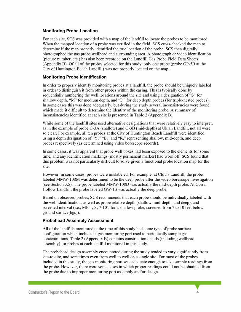
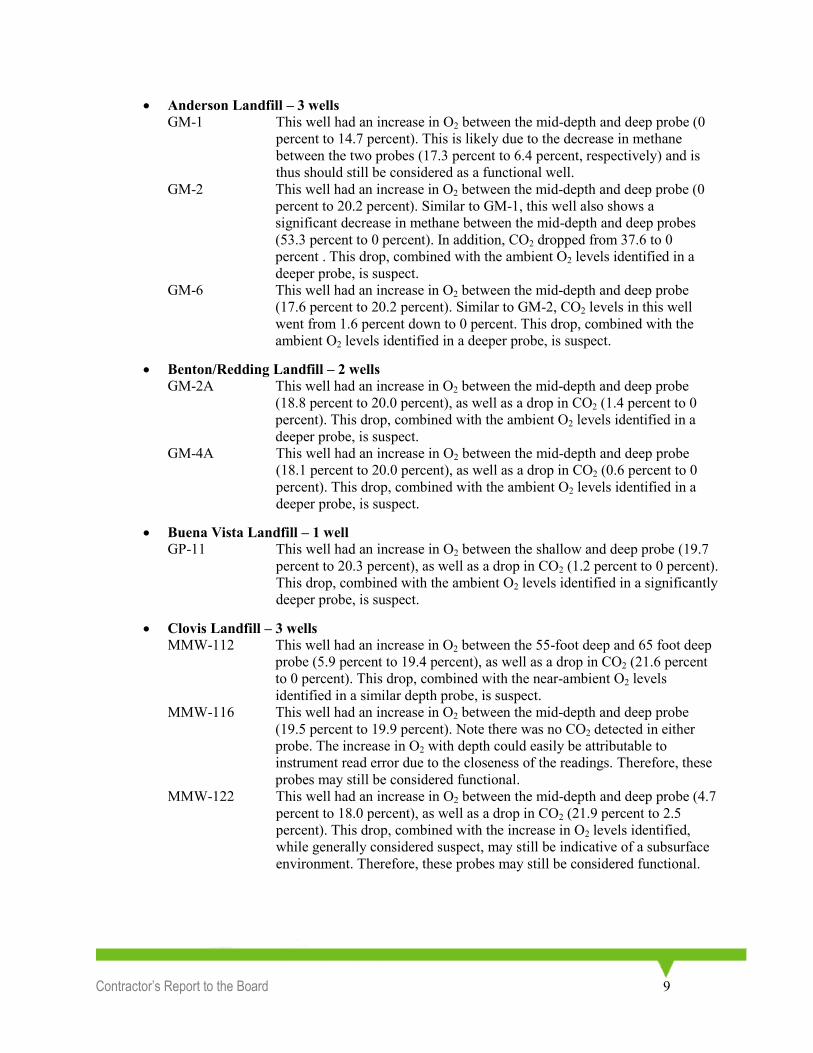
Other notable items were found down the casings of some of the probes monitored in this study.
These included salamanders, spiders, centipedes, earwigs, slugs, a bailer, and a data sheet from a
consulting firm. Below are pictures of these items taken from the borescope videos.
Soil in casing at
South Miramar Landfill
Rubber stopper at
Buena Vista Landfill
Nail through casing,
South Chollas Landfill
Roots in casing,
South Chollas Landfill
Contractor’s Report to the Board 16
In general, minor obstructions, such as rootlets, may still allow gas to travel in the probe between
the screened interval and the probhead for sampling. However, several other types of obstructions
(soil, bentonite, stoppers, etc.) will likely retard, if not stop, the flow of gases through the probe.
For this reason, SCS identified probes with significant obstructions (clogged with bentonite, soil,
flooded with water, etc.) as non-functional.
Wellhead Repair
Following completion of the probe assessment, the gas probes were re-capped with the original
probehead assembly. None of the probes monitored in this study had to have the original cap cut
off in order to monitor the probe.
Lithology Evaluation
Following completion of the field study, the verified screened interval data obtained from the
video inspections was compared to available lithologic logs from probe construction. This was
Salamander at
Ukiah Landfill Centipede at
Ukiah Landfill
Sampling data sheet at
Red Bluff Landfill

Contractor’s Report to the Board 17
done in order to determine if the probe screened intervals were placed, “preferentially adjacent to
soils which are most conducive to gas flow,” §20925(c)(1)(D).
The lithology of the screened section for each probe is listed in Table 2 (Appendix B). As shown
in Table 2, in general the probes at each landfill site are located in course-grained lithologies.
Where probes are located in finer-grained lithologies, it appears that no more coarse-grained
lithologies were located above or below the screened interval.
However, based on review of the completion depths for the various probes at the various landfills,
it is evident that the vast majority of probes were installed at pre-determined depths, due to the
similar depth ranges encountered on a per-site basis. It appears that little, if any, attention was
paid to the lithology around the installed screened section.
Probe Functionality Determination As previously indicated in the Section 3, there is no single way in which to evaluate the
functionality of a probe. It is through a combination of observations that probe functionality can
be determined. For each probe evaluated under this study, SCS reviewed the results from the
various components of the sampling program and made a determination as to the probe’s
functionality for compliance monitoring purposes. The results of this assessment are provided on
Table 2.
As shown in Table 2 (Appendix B), there were a total of 61 probes identified as non-functional,
12 probes identified as “indeterminate,” and 117 probes identified as functional. Additional detail
on the non-functional as well as probes of indeterminate functionality is presented below.
Non-Functional Probes
As shown in Table 2, a total of 32.1 percent (61 out of 190) of the probes in this study probes
were determined to be non-functional. As shown in Table 2, the reasons for non-functionality
range from clogged probes to complete lack of a screened section. In addition, it should be noted
that some, although not all, of the probes identified as non-functional may be repaired (new
probehead assembly, etc.) in order to make the probe functional in the future. A discussion of
each of these probes, listed on a site-by-site basis, is presented below:
Ukiah Landfill
GAS-9D Probe flooded‡ at approximately 26 feet bgs (above the observed top of
screen).
GAS-10M Probe clogged with soil in the middle of its screened section.
GAS-10D Probe flooded at approximately 20 feet bgs (above the observed top of
screen).
Anderson Landfill
GM-2D Probe had a minimal (<2 foot) screened interval and ambient oxygen levels
with depth.
GM-7M Probe flooded at approximately 49 feet bgs (2 feet below the observed top
of screen).
‡ A “flooded” probe is defined as a probe with greater than 25 percent of screened interval covered in
water.

Contractor’s Report to the Board 18
GM-11M Probe flooded at approximately 61 feet bgs (1 foot below the observed top
of screen).
Benton/Redding Landfill
GM-13D Probe flooded at approximately 43 feet bgs (six inches below the observed
top of screen).
GM-1 Probe had a significant (>10-foot) variation from its construction records.
GM-2D Probe flooded at approximately 16 feet bgs (above the observed top of
screen).
GM-2A Deep Probe flooded at approximately 18 feet bgs (above the observed top of
screen).
GM-4A Mid Probe had a minimal (<2-foot) screened interval.
GM-4A Deep Probe flooded at approximately 54 feet bgs (above the observed top of
screen).
Buena Vista Landfill
GP-11S Probe utilizes a rubber stopper as a wellhead valve.
GP-11M Probe utilizes a rubber stopper as a wellhead valve.
Clovis Landfill
MMW-108M Probe had a minimal (<2-foot) screened interval.
MMW-108D Probe had a minimal (<2-foot) screened interval.
MMW-112,55 Probe utilizes a bicycle valve as a wellhead valve.
MMW-112,65 Probe utilizes a bicycle valve as a wellhead valve.
MMW-116M Probe has an obstruction above the screened interval and ambient air in the
probe casing.
MMW-116D Probe is flooded at approximately 60 feet bgs (above the screened
interval).
Corral Hollow Landfill
GW-1D Probe flooded at approximately 67 feet bgs (above the screened interval).
GW-4D Obstruction observed above the screened interval.
Crazy Horse Landfill
GW-2D Probe flooded at approximately 40 feet bgs (above the screened interval).
Hillside Landfill
P-18D Probe had a minimal (<2-foot) screened interval.
Kiefer Road Landfill
GP-40M Probe had no observed screened section.
GP-44M Probe had no observed screened section.
GP-42M Screened section of this probe is covered with a pipe.
Azusa Landfill
NP1_A Missing sampling cap. Probe open to environment.
NP2_A Missing sampling cap. Probe open to environment.
NP3_A Missing sampling cap. Probe open to environment.
NP5_A Missing sampling cap. Probe open to environment.
NP10_A Missing sampling cap. Probe open to environment.
NP11_B Missing sampling cap and blocked at 12 feet bgs (above top of screened
section).

Contractor’s Report to the Board 19
Bradley Landfill
W-2B Probe blocked at a shallow depth with ambient air in the casing.
W-4 Probe had a significant (>10-foot) variation from its construction records.
W-5S Probe had a significant (>10-foot) variation from its construction records.
W-5M Probe was blocked at 72 feet bgs (within screened section of probe).
W-6 Probe was blocked at 48 feet bgs (above top of screened section).
W-9B Probe was blocked at 65 feet bgs (near top of screened section).
W-13 Probe flooded at approximately 5 feet bgs (above the screened interval).
Coyote Canyon Landfill
P-48 L3 Probe flooded at approximately 47 feet bgs (near top of screened interval).
P-48 L4 Probe flooded at approximately 58 feet bgs (above the screened interval).
P-57 L3 Probe flooded at approximately 36 feet bgs (above the screened interval).
P-57 L4 Probe flooded at approximately 45 feet bgs (above the screened interval).
P-61 L3 Probe flooded at approximately 32 feet bgs (above the screened interval).
P-61 L4 Probe flooded at approximately 46 feet bgs (above the screened interval).
City of Huntington Beach Landfill
GP-2B Probe has ambient levels of O2 at depth, whereas other probes on-site do
not.
Milliken Landfill
MLPO400-D Probe had a significant (>10-foot) variation from its construction records.
South Miramar Landfill
MW7SM-D Probe had a significant (>10-foot) variation from its construction records.
MW8SM-D Probe had a significant (>10-foot) variation from its construction records.
MW10SM-D Probe blocked at 26 feet bgs (no screened section observed).
MW11SM-D Probe blocked at 9 feet bgs (no screened section observed).
MW5SM-D Probe had a significant (>10-foot) variation from its construction records.
MW4SM-D Probe had a significant (>10-foot) variation from its construction records.
MW3SM-D Probe blocked after the reported depth of the bottom of casing and
therefore had a significant (>10-foot) variation from its construction
records.
MW2SM-D Probe had a significant (>10-foot) variation from its construction records.
Olinda Alpha Landfill
MP-6A_1 Probe had a significant (>10-foot) variation from its construction records.
MP-4_2 Probe had a bentonite blockage within the probe casing at 57 feet bgs (near
the top of the screened interval).
Otay Landfill
GP-1D Probe flooded at approximately 51 feet bgs (above the screened interval).
South Chollas Landfill
SC-18D Probe had ambient O2 levels in probe casing, unlike other probes at site of
same depth.
SC-19D Probe had ambient O2 levels in probe casing, unlike other probes at site of
same depth.

Contractor’s Report to the Board 20
Probes of Indeterminate Functionality
In addition to the 61 probes which were determined to be non-functional for compliance
monitoring purposes, there were approximately 12 additional probes whose functionality was
uncertain based on existing data, and were thus labeled with a status of “Indeterminate” in Table
2 (Appendix B). These typically include probes whose construction records vary slightly (more
than 5 feet but typically less than 10) from the borescope records, probes with near-ambient
concentrations of O2, etc. Each of the indeterminate status probes are listed below, along with a
recommendation of additional steps to be taken to determine their functionality in accordance
with the methodology presented in this study.
Anderson Landfill
GM-2M Probe had a slight variation between construction logs and video borescope
records. In order to ensure that this probe is properly screened, SCS
recommends reviewing the construction logs for the shallow nested probe
in this configuration.
Buena Vista Landfill
GP-12M Probe had an obstruction at 38.5 feet bgs and near-ambient readings at
depth. SCS recommends review of historic sampling data, as well as
potentially resampling this probe in order to verify the detected readings. In
addition, a review of the construction and lithology logs for this site would
be helpful in order to determine if the probe is screened in the proper
lithologic layer.
GP-12D Similar to GP-12M, SCS recommends remonitoring, review of historical
records, and review of the construction and lithology logs for this probe to
determine if the probe is screened in the proper lithologic layer due to near-
ambient O2 levels detected in this probe.
GP-15M SCS recommends remonitoring, review of historical records, and review of
the construction and lithology logs for this probe to determine if the probe
is screened in the proper lithologic layer due to near-ambient O2 levels
detected in this probe.
GP-15D SCS recommends remonitoring, review of historical records, and review of
the construction and lithology logs for this probe to determine if the probe
is screened in the proper lithologic layer due to near-ambient O2 levels
detected in this probe.
GP-10D SCS recommends review of the construction and lithology logs for this
probe to determine the depth of the screened section, since a rubber stopper
blocked the video borescope.
Hillside Landfill
P-17D SCS recommends remonitoring, review of historical records, and review of
the construction and lithology logs for this probe to determine if the probe
is screened in the proper lithologic layer due to near-ambient O2 levels
detected in this probe.
Milliken Landfill
MPG-51S SCS recommends review of lithology logs for this probe to determine if the
probe is screened in the proper lithologic layer.
MPG-51D SCS recommends review of lithology logs for this probe to determine if the
probe is screened in the proper lithologic layer.

Contractor’s Report to the Board 21
Olinda Alpha Landfill
MP-6A_2 Due to near-ambient O2 levels and near instantaneous vacuum recovery,
SCS recommends remonitoring and review of historical monitoring data in
order to determine if the near-ambient O2 readings in this probe at depth
are valid.
MP-5_2 Due to near-ambient O2 levels and near instantaneous vacuum recovery,
SCS recommends remonitoring and review of historical monitoring data in
order to determine if the near-ambient O2 readings in this probe at depth
are valid.
MP-5_3 Due to near-ambient O2 levels and near instantaneous vacuum recovery,
SCS recommends remonitoring and review of historical monitoring data in
order to determine if the near-ambient O2 readings in this probe at depth
are valid.
Conclusions and Recommendations
Conclusions
Probe Identification
Our overall opinion is that the method of identification used at the study landfills is satisfactory.
Of the 190 probes monitored in this study, only 25 were not properly labeled. Of those 25 probes,
only four were mislabeled. The other probes did not have any method of identification on them to
differentiate the probe depths. In order to interpret monitoring probe data, it is essential that the
field representative is monitoring the intended probe at the correct depth, and the only way to
identify the correct probe to monitor is by using a proper labeling system.
Surface Emissions
Surface emission monitoring conducted under this study generally indicated that landfill gas was
not leaking out of probe casings and into surface soil. This conclusion is based upon the gas
concentration and surface emission data contained in Table 2 (Appendix B). With few exceptions,
all of the probes that contained concentrations of landfill gas in the probe casing did not have any
surface emissions around the probe.
Significant surface emissions were detected around well GW-1 (containing probes GW1S, GW-
1M, and GW-1D) at Crazy Horse Landfill. The reason for these surface emission detections was
likely due to the significant methane concentrations (10 percent by volume) identified within the
well box. The well box likely had such significant concentrations due to the observation that one
of the probes having been left open within the box, thus allowing LFG to migrate to the surface.
Probe Construction
All of the probes that were investigated in this study were constructed of PVC piping with a
perforated or screened interval. Most of the probes were constructed using 10-foot sections of
piping, with few exceptions. At Buena Vista Landfill, a few probes were constructed with five-
foot sections of pipe. This doubles the number of joints on the probe, which could increase the
possibility of leaks. By constructing probes with longer pipe segments, the possibility of
biofouling (blockage by organic material such as roots) and blockages by bentonite and dirt is
decreased.

Contractor’s Report to the Board 22
A few probes that were monitored had screws used as a binding material for overlapping pipe
segments. This procedure should probably be avoided in order to allow future access for visual
inspections. Most of the probes that were monitored were constructed with threaded couplings
and o-rings rather than slip couplings and screws. It is recommended that threaded coupling be
used in order to minimize the possibility of gas intrusion.
Most of the wellhead assemblies on the probes were designed to function properly, with a few
exceptions. A wellhead assembly should include at minimum a locking valve with a sampling
port. Wellhead assemblies that did not meet this specification used rubber stoppers (Buena Vista
Landfill). Other valves that closed, but could not be opened without proper equipment, were the
bicycle valves at Clovis Landfill, Quick Disconnects at Bradley, Hillside, and Crazy Horse
landfills, and the sampling tube at Azusa Landfill.
The selection of probe locations, in terms of depth and topography, is crucial in the planning
process. Probes that were located close to vegetation had some degree of root intrusion either in
the screened interval or between the joints of the probe. Roots can destroy probes by cracking the
casing, rendering them useless, and one would not know a probe was cracked unless a video
borescope was sent down to investigate. In order to minimize the possibility of root intrusion on a
probe, the probe location should be placed as far away from vegetation, if possible, or should be
periodically inspected and cleared of vegetation.
The depth of the probe in relation to the water table is also a crucial step in the planning process
in order to prolong the life of the probe. Many of the probes monitored in this study extended past
the water table, and in some cases, the whole screened interval of the probe was submerged,
deeming the probe useless. In order to maximize the effectiveness of the monitoring probe, the
depth to the water table plus seasonal fluctuations in the water table should be taken into account
when determining the depth of the probe.
In addition, as indicated previously, more rigor should be applied in consideration of soil
lithology and the location of a screened interval of a compliance probe. The specified depths of
the monitoring probes within the wellbore should be installed based on the most permeable
lithology encountered, in accordance with §20925(c)(1)(D).
Durability of Materials
The materials used at the study landfills are adequate in maintaining their integrity over time with
few exceptions. A slip cap that held the quick disconnect valve on a probes at Hillside Landfill
had a crack, which was probably from a combination of heat and stress. A probe at Clovis
Landfill had stripped threading where the valve was connected to the probe. A probe at Crazy
Horse Landfill was broken about 1.5 feet below the ground surface, which was probably due to an
accident.
Overall, the remainder of the probes monitored did not have any problems with the durability of
the materials (degradation of PVC, etc.).
Statewide Probe Functionality
Based upon this study, the current approach to LFG perimeter migration monitoring probe design,
construction, and installation is unsatisfactory. An industry/regulatory standard should be set for
probe construction and installation. Recommendations that may extend the lifespan of monitoring
probes and provide for a higher level of confidence in detecting migrating LFG are discussed
below.

Contractor’s Report to the Board 23
Recommendations
Based upon the findings, SCS Engineers recommends that CCR Title 27 §20925 be modified to
include the following:
1. Probes should be constructed with longer screened segments (as opposed to shorter, and such
that screened sections do not overlap). A longer screened section reduces the possibility of
blockages by bentonite, as well as the presence of dirt and roots.
2. Wherever possible, probes should be assembled using threaded coupling, as opposed to slip
coupling and/or screwed together joints, or glued/solvent welded. This will ensure that gas
samples are collected from the screened interval of a probe as opposed to areas where casing
might leak due to a bad seal and/or screwed-together joints. SCS understands that some
portions of a probe (e.g., endcap and wellhead) cannot be preconstructed and thus, may
require a slip-type fitting.
3. All probes should be constructed using a non-proprietary locking valve on the probehead
assembly (labcock valve, quick connect valve, or similar). This will ensure that valid pressure
readings can be obtained from the probe from on-site personnel as well as regulatory
agencies.
4. Probes should be preferentially located as far away from surface vegetation as possible in
order to avoid root intrusion into shallow probes.
5. Development of a standard probe specification and construction criteria.
6. Require professional geologist/engineer certification of installed/completed probes, including
rationale for preferential placement of mid-depth probe(s) based on lithology.
7. Periodic functionality assessments should be initiated for all probes at every landfill site. One
recommended implementation would be to perform a functionality assessment every ten
years (following initial probe installation). The ten-year term is based on the average age of
the probes evaluated in this study, which ranged from under five years to more than 25 years.

Contractor’s Report to the Board 24
Appendix A
November 2006 Work Plan
Environmental Consultants 3050 Fite Circle 916 361-1297
Suite 106 FAX 916 361-1299
Sacramento, CA 95827 www.scsengineers.com
WORK PLAN FOR
ASSESSMENT OF LANDFILL GAS
MONITORING WELL VIABILITY AT
TWENTY CALIFORNIA LANDFILLS

Contractor’s Report to the Board 25
Prepared For:
California Integrated Waste Management Board
1001 I Street
Sacramento, California 95814
Contract: IWM-05102
Prepared By:
SCS Engineers
3050 Fite Circle, Suite 106
Sacramento, California 95827
File No. 01206102.00
November 2006
Contractor’s Report to the Board 26
This Work Plan for the Assessment of Landfill Gas Monitoring Well Viability at Twenty
California Landfills, dated November 2006, was prepared and reviewed by the following:
Raymond H. Huff, R.E.A.
Senior Technical Manager
Wayne Pearce, P.G.
Senior Project Manager
SCS ENGINEERS

Contractor’s Report to the Board 27
TABLE OF CONTENTS
Section Page
1.0 ................................................................................................... INTRODUCTION AND OBJECTIVES
...................................................................................................................................................................... 1
2.0 .......................................................................................... PROJECT OBJECTIVES AND APPROACH
...................................................................................................................................................................... 1
3.0 .......................................................................................................................... SAMPLING PROGRAM
.................................................................................................................................................................... 30
3.1 Selection of Gas Probes ............................................................................................................. 30
3.2 Notification and On-Site Arrival ............................................................................................... 30
3.3 Ambient Conditions .................................................................................................................. 30
3.4 Surface Conditions .................................................................................................................... 30
3.5 Probe Gas Monitoring ............................................................................................................... 31
3.6 Pressure Integrity Test ............................................................................................................... 31
3.7 Video Borescope Inspection ...................................................................................................... 31
3.8 Wellhead Repair ........................................................................................................................ 32
4.0 ............................................................................................ DATA EVALUATION AND REPORTING
.................................................................................................................................................................... 32
4.1 Comparison of Field Data to Records ....................................................................................... 32
4.2 Preparation of Well Viability Report ........................................................................................ 32
4.3 Preparation of Greenhouse Gas Emissions Report .................................................................... 32
Tables
Table 1 – Landfills Selected for Study
Appendices
A Quality Assurance/Quality Control Plan
B Sampling and Analysis Plan
C Health and Safety Plan

Contractor’s Report to the Board 28
WORK PLAN FOR
ASSESSMENT OF LANDFILL GAS
MONITORING WELL VIABILITY AT
TWENTY CALIFORNIA LANDFILLS
INTRODUCTION AND OBJECTIVES
The California Integrated Waste Management Board (CIWMB) has retained SCS Engineers (SCS) to conduct a study of existing landfill gas (LFG) monitoring wells (probes) located at 20 landfills throughout the State. The intent of the study is to determine if the existing gas probes have been designed, constructed, and are functioning properly and are capable of detecting lateral migration of landfill gas. If it is shown that a significant number of gas probes are not functioning properly due to inadequate design, improper installation, normal deterioration, subsurface changes or vandalism, landfill gas migrations may be underestimated or undetected, potentially leading to dangerous conditions for persons and facilities located near landfills and to adverse effects on the environment. Also, the amount of landfill gas being generated and released from landfills may be underestimated and models for emission of greenhouse gasses (GHG) may need to be revised. Finally, depending on the results of the study, existing regulations may need to be modified to ensure that gas probes installed around landfills are functional and capable of detecting migrating landfill gas, if present.
The assessment of landfill gas monitoring well viability to be completed under this study will focus on visual and physical testing of 200 landfill gas probes located at 20 sites in California. This work plan presents the methods that will be used to accomplish this study.
PROJECT OBJECTIVES AND APPROACH
CIWMB has selected 20 landfill sites in northern and southern California to be included in this study. The landfills were selected to include a variety of landfill sizes, geomorphic and geologic settings, and the presence of relatively deep gas probes (40-100 feet). These deeper probes have the greatest potential for installation problems, ground water infiltration, or other conditions that could render them ineffective monitoring points. Table 1 presents a listing of the landfills to be included in the study.
SCS reviewed internal files regarding the sites selected by CIWMB to determine if landfill gas probe information existed, for these sites, in the SCS files. Data of concern included:
Locations of probes;

Contractor’s Report to the Board 29
Construction details and as-built diagrams;
Completion depths;
Gas monitoring history; and
Site geology.
Table 1.
Landfills Selected for Study
Landfill Name County City SWIS#
Nort
hern
CA
Sites
Clovis Fresno Clovis 10-AA-0004
Ukiah Mendocino Ukiah 23-AA-0019
Crazy Horse Monterey Salinas 27-AA-0007
Kiefer Sacramento Sloughhouse 34-AA-0001
Coral Hollow San Joaquin Tracy 39-AA-0005
Hillside San Mateo Colma 41-AA-0008
Buena Vista Santa Cruz Watsonville 44-AA-0004
Anderson Shasta Anderson 45-AA-0020
Redding/Benton Shasta Redding 45-AA-0019
Red Bluff Tehama Red Bluff 52-AA-0001
South
ern
CA
Sites
Azusa Los Angeles Azusa 19-AA-0013
Bradley Los Angeles Sun Valley 19-AR-0008
HB Sports Complex Orange Huntington Beach 30-AB-0026
Olinda Alpha Orange Brea 30-AB-0035
Coyote Canyon Orange Newport Beach 30-AB-0017
Upland San Bernardino Upland 36-AA-0005
Milliken San Bernardino Ontario 36-AA-0054
South Chollas San Diego San Diego 37-AA-0022
South Miramar San Diego San Diego 37-AA-0033
Otay Landfill San Diego Chula Vista 37-AA-0010

Contractor’s Report to the Board 30
After obtaining as much data as possible from the SCS files, a data request was made to CIWMB for missing data. This included those sites for which SCS did not have any data, or for portions of data not in our files.
The actual probes to be investigated at each landfill will be selected by CIWMB staff, at each site, on the day or days of each site study.
SAMPLING PROGRAM
SCS will accomplish the landfill gas probe viability testing through a standardized approach to be applied at all 20 landfills and 200 gas probes. All data collected for each probe investigation will be recorded on a Landfill Gas Probe Field Data Sheet.
Selection of Gas Probes
CIWMB staff will select the probes to be investigated at each landfill. The probes to be studied will be selected upon arrival at each site.
3.2 Notification and On-Site Arrival
Prior to the planned arrival date for each landfill, the CIWMB will contact the landfill operator to let them know when Board and SCS staff are planning to be on-site. If the owner/operator wishes to have a representative present during the probe study, arrangements will be made to accommodate the representative.
Ambient Conditions
For each gas probe to be studied, SCS will first record ambient conditions including atmospheric conditions, barometric pressure, temperature, wind speed and direction. These will be recorded on the Landfill Gas Probe Field Data Sheet.
Surface Conditions
For each gas probe to be studied, SCS will verify the probe identification to determine if it is properly labeled and properly located on site maps. SCS will then digitally photograph the gas probe wellhead and surrounding area. Alternatively, the wellhead and surrounding area may be recorded on a video

Contractor’s Report to the Board 31
recorder. Photograph or video identification (picture number, etc.) will be recorded on the Landfill Gas Probe Field Data Sheet.
A scan will be made of the surface, in a 5-foot radius around each probe, using an RKI Eagle to measure methane emissions. If no emissions are detected, this will be recorded on the Landfill Gas Probe Field Data Sheet. If methane emissions are detected, the concentration and location will be recorded on the Landfill Gas Probe Field Data Sheet.
Probe Gas Monitoring
Before the gas probes are opened for inspection, SCS will determine gas concentrations and pressure in each probe. This will be done for methane, carbon dioxide, oxygen, carbon monoxide, and hydrogen sulfide. These readings will be collected using GEM 2000 and RKI Eagle instruments. Readings will be monitored until a steady state level has been achieved for 30 seconds (if possible). Gas concentrations observed will be recorded on the Landfill Gas Probe Field Data Sheet.
Pressure Integrity Test
The pressure integrity test consists of the application of vacuum to each probe and noting the change in vacuum over time. The integrity test will be conducted immediately following the gas monitoring activities.
Following gas monitoring activities (Section 3.5, above), the probe valve will be closed prior to turning off and/or disconnecting the GEM2000 from the probe. A sampling train including a vacuum/pressure gauge, control valve, and vacuum pump will then be connected to each probe. The probe valve will then be opened and a negative pressure suitable for the purpose will be applied. The initial vacuum pressure will be recorded on the Landfill Gas Probe Field Data Sheet. After applying the vacuum, the sampling train valve will be closed and the residual vacuum monitored. The rate of residual vacuum decline will be noted on the Landfill Gas Probe Data Sheet.
Video Borescope Inspection
After conclusion of the vacuum/pressure test, the well cap will be removed from each of the 200 study probes and the video borescope camera will be lowered into the probe. First, the probe identification (landfill and probe number) will be entered onto the video record. Then, as the camera is lowered, each 5-foot marker on the borescope will be entered via keyboard onto the video record of the probe. Features such as casing joints, top and bottom of screen, water level (if present), and bottom of probe will be identified on the video record, as well as any other remarkable features such as casing or screen damage or screens not constructed as designed. At all identifiable features, the depth will be entered onto the video record via keyboard. The depth will be determined to at least the nearest 1/10
th of a foot by
measuring up from the nearest 5-foot marker on the probe.

Contractor’s Report to the Board 32
The video record for each probe will be recorded onto either temporary storage media (Compact Flash Cards) and later transferred to a computer hard drive, or recorded directly to a mass storage hard drive.
Wellhead Repair
Following completion of the video borescope inspection, the gas probes will be re-capped with the original PVC cap or, if the original cap had to be cut off, replaced with a similar well cap. To the extent possible, the well cap will be configured with the same sampling port as the original.
DATA EVALUATION AND REPORTING
Comparison of Field Data to Records
Following completion of each landfill field data collection, data obtained from the video inspections will be compared to the records available for the probes. This will include comparison of construction features and installation depths to as-built drawings and/or well logs. Probe locations will be compared to available maps to determine if the probes are properly located and identified.
Preparation of Well Viability Report
SCS will prepare a Gas Well Viability Report based on the observations noted during the field work, video borescope records, and existing data on the probes. The report will list, on a probe by probe basis, the results obtained and whether each probe is considered viable as a gas monitoring point. Landfill Gas Probe Field Data Sheets for all probes will be included in the report as an appendix. The report will also contain video records of the video borescope inspections on either CD or DVD disks, which are on file with CIWMB.
Using these results, SCS will draw conclusions on all aspects of probe functionality taking into account construction problems, durability of materials, changes in subsurface conditions like blockage by ground water, vandalism, and in addition, considering the possibility of errors related to probe miss-identification. SCS will also make recommendations regarding the overall approach to installation of gas probes and draw conclusions as to statewide probe functionality as the sole means for detection of landfill gas migration at landfills.
Preparation of Greenhouse Gas Emissions Report
Using the data from the study, SCS will also evaluate how the results of this viability study of
LFG monitoring probes can be used to supplement or refine the California Energy Commissions’
(CEC’s) proposed LFG emissions model.
Contractor’s Report to the Board 33
The integrity of LFG migration probes may present a potential conduit for LFG/methane that is
not accounted for in the CEC flux study. The results of our study may suggest that lateral probe
migration may be an input parameter to the CEC model or at least be further studied as part of
the CEC project. In addition, SCS will evaluate the use of various published models for LFG
migration in porous media to assist in the evaluation.
In addition, it should be noted that LFG probes are used as an assessment tool to determine how
effective a LFG collection and control system is at controlling subsurface LFG migration. This
study will assist in determining whether the data derived from existing probe designs,
particularly multi-depth probes, is sufficient to use for this purpose. If so, LFG probe data may
be a recommended variable for the CEC’s LFG emissions model for determining collection
efficiency. If not, our report may recommend that probe data not be used for this purpose.
In our final greenhouse gas emissions report, SCS will summarize this evaluation and provide
recommendations as to how we see these data should be used for the CEC project. If feasible,
we would recommend modifications to the CEC study or at least the inclusion of additional input
variables to the CEC model, which could increase the accuracy of the GHG estimates.
APPENDIX A
QUALITY ASSURANCE/
QUALITY CONTROL PLAN
QUALITY ASSURANCE/QUALITY CONTROL PLAN
CIWMB GAS PROBE VIABILITY STUDY
OBJECTIVE
The objective of the Quality Assurance/Quality Control Plan is to establish standard
procedures for the study in order to ensure that data collected at all 20 landfills and all 200
gas probes to be investigated are comparable. The procedures described herein should be
followed for all probe investigations. If an unforeseen condition results in an alteration of the
procedures, these should be carefully documented.

Contractor’s Report to the Board 34
This study entails field observations and measurements only, followed by preparation of the
Gas Probe Viability Report. No samples are to be collected for laboratory analyses.
Therefore, the procedures given in this QA/QC Plan are limited to field activities and
recording of field data and observations.
SUMMARY OF ACTIVITIES
Activities to be accomplished for this study are described in the Work Plan. For each
landfill and each probe to be investigated these include:
1. Arrive at landfill and select probes to be studied (CIWMB staff to select probes).
2. For each probe inspection, record weather conditions.
3. Confirm probe identification and location compared to existing maps and numbering.
4. Inspect and photograph the wellhead and vicinity to document conditions.
5. Scan the surface around each wellhead for methane emissions.
6. Measure ambient pressure/vacuum in the probe.
7. Obtain gas concentration readings.
8. Connect wellhead vacuum test equipment and conduct a vacuum integrity check.
9. Remove the wellhead and perform and record a video borescope inspection of the
probe.
10. Complete the probe inspection and replace/rebuild the probe wellhead.

Contractor’s Report to the Board 35
FIELD QA/QC PROCEDURES
A two-person team will be used for the field activities. This is to manage the video borescope equipment, which is best accomplished by two persons, and record filed data and observations. This requires a set system of data recording and communications between personnel. The primary instrument for field data recording will be the Landfill Gas Probe Field Data Sheet. An example data sheet is provided at the end of this Appendix. The data sheet is two-sided and one should be completed for each probe investigated. When completing the Landfill Gas Probe Field Data Sheet, the following procedures should be used:
Record data using an indelible ink pen.
Cross out errors with single stroke and record correction (or complete new data sheet).
When one person is recording data being collected and read aloud by another, the person recording the data should verbally confirm the data back to the originator. This is to confirm that the information was heard and recorded properly.
One person should principally record the data for each probe investigation. The other person should check the Landfill Gas Probe Field Data Sheet, after completion of each probe investigation, for completeness and accuracy.
After completion of each landfill investigation (10 probes), the Landfill Gas Probe Field Data Sheets should be copied and sent to the Project Manager.
Other field QA/QC procedures involve the proper calibration of the instruments used to record the data. Instrument descriptions, serial numbers, calibrations procedures used, or most recent calibration data (if calibrated by others), will be recorded in the field notes for each landfill investigation.
REPORT QA/QC PROCEDURES
After field investigations have been completed all landfills, data collected will be summarized in the Landfill Gas Probe Viability Report. Field Data Sheets will be included in an Appendix of the report. A draft version of the Report will be reviewed by the SCS field personnel that completed the investigation, and by at least one senior staff member familiar with the project.
Contractor’s Report to the Board 36
APPENDIX B
SAMPLING AND ANALYSIS PLAN
SAMPLING & ANALYSIS PLAN
CIWMB GAS PROBE VIABILITY STUDY
OBJECTIVE
The objective of this Sampling and Analysis Plan (SAP) is to provide a summary of data
collection activities to be accomplished. The contents of this SAP mirror the activities described
in the Work Plan. Because no samples are being collected for laboratory analysis, the sampling
and analysis activities are limited to field observations using real-time instruments and
observations. These are addressed in the following Standard Operating Procedure used by SCS
Engineers for Landfill Gas Probe Testing.
STANDARD OPERATING PROCEDURE No. 101-rev 0
PERIMETER PROBE MONITORING AND SAMPLING Revised January 30, 2006
Reviewed and Approved by Mark Beizer- SCS Engineers
1.0 PURPOSE AND SCOPE
In compliance with subparagraph (c)(4)(B) of South Coast Air Quality Management District (SCAQMD) Rule 1150.1, the Stipulated Permanent Injunction, and the Operations Plan (Class I Part B permit),

Contractor’s Report to the Board 37
perimeter probes have been installed at specified locations outside the waste disposal areas at the BKK Landfill. This SOP contains procedures for the monitoring and sampling of the perimeter probes.
2.0 RESPONSIBILITIES AND QUALIFICATIONS
The OM&M Task Manager (TM) is responsible for assigning project staff who are qualified to perform the tasks listed in this SOP.
The project staff and subcontractors assigned to perform these operations are responsible for completing their tasks according to this and other appropriate procedures. All staff are responsible for reporting deviations from the procedure or nonconformance to the TM.
Only qualified personnel shall be allowed to perform this procedure. At a minimum, staff qualified to perform these activities will be required to have:
Read this SOP and corresponding Activity Hazard Analysis
Signed the attached form to indicate to the TM that all procedures contained in this SOP are
understood and will be followed
Completed the OSHA 40-hour training course and/or 8-hour refresher course, as appropriate
Previously conducted these operations in a manner generally consistent with the procedures
described in this SOP
A demonstrated ability based on previous experience performing similar activities
Medical monitoring in accordance with HAZWOPER requirements
Project staff that do not have previous experience performing these operations will be trained onsite by qualified personnel, and will be supervised directly until they have demonstrated an ability to perform the procedures.
3.0 PROCEDURES FOR PROBE MONITORING AND SAMPLING
3.1 PROBE MONITORING AND SAMPLING
3.1.1 Equipment
Personnel conducting perimeter probe monitoring and sampling will require the following equipment.
Contractor’s Report to the Board 38
LANDTEC GEM-500™ or -2000™
Magnehelic gauges
Flame ionization detector
Tygon tubing
Calibration Gases
Sample containers (Tedlar Bags or Stainless Steel Canisters)
Pen
Paper / Field Forms (Probe monitoring log, chain-of-custody)
Latex Gloves
Safety Glasses
Steel-toed Boots
Orange Traffic Vest
The LANDTEC GEM-500™ or -2000™ electronic instrument that is calibrated to measure the concentration of methane, carbon dioxide and oxygen gas, as well as measure static pressure and atmospheric pressure (only the GEM-2000™ can read atmospheric pressure). The LANDTEC GEM-500™ or -2000™ is also equipped with an electric pump that is capable of pumping soil gas at a maximum flow-rate of 300 cubic centimeters per minute (cc/min). The LANDTEC GEM-500™ or -2000™ instrument will be calibrated for methane by manufacturer specifications, using specific concentrations of high-quality calibration gases. The GEM-500™ or -2000™ will be calibrated prior to each day of monitoring and documented on the calibration log.
3.1.2 Procedure [Field crews use an OVA for readings]
Probe testing will be conducted using procedures described in the Rule 1150.1 guidelines. An approved gas extraction monitor (LANDTEC GEM-500™ or -2000™) will be used to measure the volume concentration of total organic compounds (TOCs), expressed as percent of ppm methane. The GEM-500™ or -2000™ instrument is also used to measure the static pressure in the probe and atmospheric pressure prior to monitoring gas composition. All data are recorded and stored in the GEM-500™ or -2000™ at the time of monitoring. Each reading is stored with a date and time stamp. Data are to be uploaded from the GEM-500™ or -2000™ to the SCS database.
Upon arriving at the probe, personnel should perform the following steps:
1. Attach tubing from a Magnehelic gauge. Open the stopcock and measure the pressure in
inches of water column.
2. Record the probe identification number, date, time and name of monitoring personnel on
the probe monitoring log. For multiple depth probes, confirm the sub-probe identification
number or letter and record on the probe monitoring log.
3. Connect an end of a quarter-inch, inner diameter, Tygon tube (approximately a foot in
length) to the gas inlet port on the GEM-500™ or -2000™.
4. Connect the opposite end of the Tygon tube onto the soil gas probe’s outlet sample port.
5. Open the valve connected to the soil gas probe to channel gas from the soil, through the
Tygon tube, to the GEM-500™ or -2000™.
6. Static pressure build-up in the soil is recorded by the GEM-500™ or -2000™.

Contractor’s Report to the Board 39
7. The atmospheric pressure is also recorded by the GEM-2000™ just prior to or
immediately after recording the static pressure in the probe.
8. Activate the electric pump on the GEM-500™ or -2000™ and operate until three probe
volumes have been pumped out of the probe. An example of the calculation method
used to determine the volume to pump out of a soil gas probe is included in Attachment
1.
9. The gas composition (methane, oxygen, carbon dioxide and balance gas at concentration
range of 1,000 ppmv to 100 percent by volume) is recorded by the GEM-500™ or -
2000™. Lower range measurements are obtained using a flame ionization detector (0 to
1,000 ppmv). If the oxygen level in the probe drops below 16 percent by volume, flame-
out of the detector is possible. Use a diluter connected to the tip of the detector to obtain
a probe reading.
10. Based on field measurement obtained with the GEM-500™ or -2000™, if the TOC
concentration in any of the probes is five percent by volume or greater, one 10-liter bag
sample shall be collected from the probe(s) with the highest concentrations above five
percent (up to a maximum of five probes). The sample will be taken by connecting a
Tygon tubing from the GEM-500™ or -2000™ to the Tedlar bag and operating the
electric pump on the GEM-500™ or -2000™ continuously until the bag is filled. If
canisters are used to collect the sample, they are pre-evacuated and do not need the
GEM pump for filling.
11. If a sample has been taken, record the sample number on the probe monitoring log, on
the sample container and complete the chain-of-custody form to accompany the sample
to the laboratory.
12. If a field QA/QC sample blank is required by the SAP, label and prepare the sample
container and record the sample identification information of the probe monitoring log and
the chain-of-custody.
13. If a duplicate sample is required by the SAP, obtain the sample following the procedures
in step 9 and 10 above.
14. Close the valves on the probe and/or the sample container then disconnect the Tygon
tubing.
15. For probe locations with multiple depth casings, repeat the above procedures.
All collected samples will be submitted to an approved laboratory for analysis of methane, total non-methane hydrocarbons (TNMHCs), and rule 1150.1 core group toxic air contaminants or other testing as may be described in the special investigations.
Probes that have readings of > 1,000 ppmv for 2 consecutive days are classified as “targeted probes”. Targeted probes require an engineering analysis to determine mitigation methods. The engineering analysis will include the following tasks:
A thorough review of targeted probe and adjacent probe monitoring data.
Review the geology
Examine for possible liquid impacts
Review the influence of nearby gas extraction wells in the area of affected probes
Review possible barometric pressure effects
Contractor’s Report to the Board 40
Review the records on system operation for the previous 2 week period.
To help ensure the requirements of the site compliance plan are met, SCS will promptly notify the Working Group if any of the probe GEM-500™ or -2000™ are approaching 1,000 ppm methane by volume. This will enable the Working Group to implement appropriate mitigation measures as soon as possible. SCS will subsequently perform follow-up GEM-500™ or -2000™ monitoring at the affected probe no later than the allowable time after the initial monitoring. Mitigation monitoring results will be documented on the probe monitoring log.
3.1.3 Frequency
The perimeter probes will be monitored quarterly. Probes that exceed 1,000 ppmv for two consecutive days will be classified targeted probes. Targeted probes are measured daily until the gas concentration is less than 1,000 ppmv; once the < 1,000 ppmv value is achieved the probes are monitored weekly and the probe is considered declassified. If a declassified probe has no gas readings exceeding 500 ppmv for a period of three months, the probe monitoring frequency is reduced to monthly. If concentrations remain below 500 ppmv for a period of six months, the probe is reclassified as a quarterly probe.
3.1.4 Quality Control Procedures
After each perimeter probe has been evacuated and measured for TOCs, sample control forms are to be completed detailing the sample container identification number, along with the date and time of sample collection.
Upon the completion of sampling, samples are to be numbered to coincide with probe locations, dated and delivered to the laboratory. All samples will be analyzed within a 72-hour period following collection.
Chain-of-Custody forms are to be completed before the samples are delivered to the laboratory. The chain-of-custody forms will contain an identification number for reference to probe number and location. Sample custody forms are to be released and signed by field staff, and will accompany samples to the laboratory, where they will be signed upon receipt.
4.0 DOCUMENTATION
All data are recorded and stored in the GEM-500™ or -2000™ at the time of monitoring. Each reading is stored with a date and time stamp. Other field readings, (static pressure and flame ionization detector readings) will recorded be on field forms. In the office:
Data are to be uploaded from the GEM-500™ or -2000™ to the SCS database. This program stores each set of probe readings in a site file. The data can be accessed for review by authorized users. Probe monitoring and sampling activities are to be recorded on the probe monitoring log. After each perimeter probe has been evacuated and measured for TOCs, sample control forms are to be completed detailing the sample container identification number, along with the date and time of sample collection. The original probe monitoring logs and sample control forms are to be kept on file at the site.
5.0 MODIFICATIONS TO SOP

Contractor’s Report to the Board 41
This SOP is to be reviewed periodically and no less than once a year to determine if any modifications are required. In the event the SOP needs any changes, those modifications will be discussed with DTSC and will not be implemented until DTSC has approved the revised SOP.
6.0 LIST OF RELATED SOPs
SOP 102 – Landfill Gas Sampling – Extraction Well or Header
APPENDIX C
HEALTH AND SAFETY PLAN
SITE HEALTH AND SAFETY PLAN
LANDFILL GAS PROBE VIABILITY STUDY
SCS JOB #01206102.00
JOB LOCATION: 20 Landfill sites located throughout California. Specific landfills and locations are listed in Table 1.
Table 1.
Landfills Selected for Study
Landfill Name County City SWIS#
Nort
hern
CA
Sites
Clovis Fresno Clovis 10-AA-0004
Ukiah Mendocino Ukiah 23-AA-0019
Crazy Horse Monterey Salinas 27-AA-0007
Kiefer Sacramento Sloughhouse 34-AA-0001
Coral Hollow San Joaquin Tracy 39-AA-0005
Hillside San Mateo Colma 41-AA-0008
Buena Vista Santa Cruz Watsonville 44-AA-0004
Anderson Shasta Anderson 45-AA-0020
Redding/Benton Shasta Redding 45-AA-0019

Contractor’s Report to the Board 42
Red Bluff Tehama Red Bluff 52-AA-0001
South
ern
CA
Sites
Azusa Los Angeles Azusa 19-AA-0013
Bradley Los Angeles Sun Valley 19-AR-0008
HB Sports Complex Orange Huntington Beach 30-AB-0026
Olinda Alpha Orange Brea 30-AB-0035
Coyote Canyon Orange Newport Beach 30-AB-0017
Upland San Bernardino Upland 36-AA-0005
Milliken San Bernardino Ontario 36-AA-0054
South Chollas San Diego San Diego 37-AA-0022
South Miramar San Diego San Diego 37-AA-0033
Otay Landfill San Diego Chula Vista 37-AA-0010
PROJECT DESCRIPTION: The project will consist of the in-field evaluation of 10 landfill gas (LFG) perimeter migration monitoring probes at each landfill site. Activities will include video-logging, probe monitoring, and pressure-testing of each probe in order to determine the probe’s integrity and viability in effectively monitoring greenhouse gas migration from the subsurface. Additional detail on the proposed scope of work is presented in the November 2006 workplan, Work Plan for Assessment of Landfill Gas Monitoring Well Viability at 20 California Landfills.
ON SITE ORGANIZATION AND COORDINATION:
Project Team Leader: Wayne Pearce, SCS
Primary Health & Safety Officer: Ray Huff, SCS
On-Site Safety Officer: Ryan Farrell/Steve Crowsdale, SCS
Client Representative: John Bell, CIWMB
CHEMICAL HAZARD EVALUATION: While the proposed workplan does not anticipate encountering raw landfill gas (LFG), a brief listing of some of the priority pollutant chemicals of chief regulatory concern, which may be found in significant (percent-range) levels within raw LFG (specifically methane) is contained on the attached MSDS sheets. Consult National Institute of Occupational Safety and Health (NIOSH) Chemical Hazards Guide for proper precautions to be taken for each constituent (a copy of this guide should be found in each PPE bag issued by SCS). Concentrations of these and other constituents known to exist in LFG will be continuously monitored during all on-site activities.

Contractor’s Report to the Board 43
PHYSICAL HAZARD EVALUATION:
Landfill gas and subsurface combustion emissions
Methane gas building up in and below-grade structures and sampling equipment
Potentially harmful microorganisms in decomposing refuse (if encountered)
Animals (e.g., rats) and vectors (e.g., mosquitoes).
Working in proximity to heavy equipment
Slippery footing on slopes could be present on the landfill.
Proper precautions should be taken to avoid these possible hazards.
NATURAL HAZARDS: The following hazards could be potentially encountered while performing the investigation and assessment functions of the project:
Sun Exposure- Prolonged exposure to the sun may cause fatigue, headaches, rash and/or sunburns
Animals- Rodents, poisonous insects, snakes, and/or plants are a natural part of any ecosystem.
SITE SECURITY/SITE CONTROL: A controlled work area will be prepared for the assessment effort. The PVLF is a controlled site, with access only allowed to trained personnel. As such, site security/control efforts will include coordination with LACSD personnel on cordoning off sampling/work areas and access control to on-site structures and vehicles.
MONITORING EQUIPMENT: Continuous monitoring of the breathing zone in the active work area will be conducted using a RKI Eagle. The RKI Eagle has a multi-gas meter capable of monitoring methane (both percent lower explosive limit [LEL] and percent by volume), carbon monoxide (in parts per million [ppm]), hydrogen sulfide (in ppm), and percent oxygen. In addition, a Foxboro Organic Vapor Analyzer (OVA) will also be used on an as-needed basis to evaluate total organic vapors (TOV) as methane present in ambient air in the part per million range.
SCS has established breathing zone action levels, based on the OSHA PELs for various components and the LEL for methane. A summary of the pertinent action levels for this project are summarized on Table 2. In the event that any of the action levels are exceeded in the breathing zone of the active work area for an extended period (more than 5 minutes of continuous monitoring), action will be taken to either address the source of emissions (i.e covering area per project description) or upgrade of personal protective equipment (PPE) from Level D (steel-toed boots, hard-hat, etc.) to levels C (level D PPE + half-facepiece respirator).
However, in the event that unsafe oxygen and/or carbon monoxide levels are encountered in the breathing zone of the active work area, operations in the active work area will cease and the level of PPE required for the project will be reevaluated by the Project Health and Safety Officer.

Contractor’s Report to the Board 44
TABLE 2 – AIR MONITORING ACTION LEVELS
Parameter Instruments Action Level
Methane and TOV as Methane RKI Eagle and At or above 10% LEL
Foxboro OVA (e.g., 5,000 ppm)
Carbon Monoxide RKI Eagle Above 50 ppm
Hydrogen Sulfide RKI Eagle Above 20 ppm
Oxygen RKI Eagle Below 19.5% or above
23.5%
% Percent gas by volume
% LEL Percent of the lower explosive limit
ppm Parts per million
STANDARD PROCEDURES: The following are standard procedures that SCS will follow while on site:
No smoking: Smoking will not be allowed at anytime on site unless designated smoking areas are available.
Personal Protective Equipment: SCS personnel will wear Level D protection in the active work area. Level D protection includes steel-toed work boot, work gloves, hard-hat, eye protection, and high visibility work vest. Additional personal protective equipment for Level C protection will be available in the employee’s PPE bag. The PPE bag will be with the employee at all times.
Note: All site employees will conduct work activities in a safe manner at all times. This includes general safe work practices, accident reporting, and health and safety plan review.
FIELD HYGIENE: Avoiding and/or minimizing contact with refuse, contaminated soil, etc. greatly simplifies decontamination and reduces the potential of injury. Skin abrasions, cuts, and scratches enhance potential for infectious agents or chemicals to penetrate the body. Skin injuries should be adequately covered. Washing with antibacterial soaps and/or disinfectants minimizes infection. Hands should be thoroughly cleaned prior to eating, drinking, or other hand-to-mouth activities. Care should also

Contractor’s Report to the Board 45
be taken not to swipe debris from the eyes with soiled fingers during any work activity involving refuse or contact with soil.
EMERGENCY MEDICAL CARE: Permanent first aid equipment will not necessarily be found on site; first aid kits are kept in PPE bags as well as in company trucks. List of emergency phone numbers:
Agency/Facility Telephone Number
Ambulance 911
Police 911
Fire 911
Hospital 911
SCS Long Beach Office (800) 326-9544
Project Leaders
Northern California
Wayne Pearce – cell phone (916) 251-6425
Southern California
Ray Huff – cell phone (562) 355-6334
EMERGENCY PROCEDURES: Stop work activities when injury or accident occurs. As needed notify appropriate emergency agency. Administer first aid if possible. Contact the SCS Project Manager and Health & Safety Coordinator as soon as possible.
APPROVAL SIGNATURE: ________________________________________
All site personnel have read the above plan and are familiar with its provisions.
Name Signature Date
Project Team Leader: __________________ _____________ ____________
Health & Safety Officer: __________________ _____________ ____________
Other Site Personnel: __________________ _____________ ____________
__________________ _____________ ____________

Contractor’s Report to the Board 46
Appendix B
Probe Functionality Investigation Summary and Determination
This appendix contains spreadsheets (MS Excel 2 MB) with all pertinent data obtained from the
landfill gas probe functionality study for each of the 20 study landfills.
These spreadsheets are not included in this document but can be downloaded from the website.
This data is categorized by site and actual probe number and includes (for each probe) initial
probe conditions, all collected gas monitoring data, vacuum testing results, video borescope
findings, a lithology evaluation, and a determination of probe functionality.

Contractor’s Report to the Board 47
THIS PAGE LEFT INTENTIONALLY BLANK