Embed Size (px)
Citation preview
Indian Journal of Chemistry Vol. 42A, August 2003, pp. 1833-1839
La(l_x)AxMn(l_y)By0 3 supported on honeycomb substrate - Characterization and application for catalytic converter
R B Biniwale*, M A Bawase, N K Labhsetwar & R Kumar
National Environmental Engineering Research Institute, Nehru Marg, Nagpur 440 020, India
Received 15 May 2002; revised 25 March 2003
Perovskite catalysts are reported as substitute to noble-metal catalysts for automobile catalytic converter. The low surface area and non-compatibility with alumina washcoat had been the major problems for limiting the application of perovskite for auto-exhaust treatment. Lao.7SrO.3Mno.95 Pto.OS0 3 supported on alumina washcoated honeycomb substrate has been prepared in this study. The detail characterization, at each step of preparation of catalyst coated substrate, using techniques such as BET SA, porosity, pore size distribution, TGA and XRD have been carried out and discussed. Characterization results reveal the possible use of supported perovskite for automobile exhaust treatment.
A typical auto-exhaust catalytic converter consists of five parts viz. substrate, alumina washcoat, catalyst, ceramic mat and metallic shell. Honeycomb monolith substrates are most suitable to meet the requirement of large contact area for interaction between catalyst and exhaust gas. The honeycomb type of substrates is either ceramic or metallic. Ceramic honeycomb substrate is made up of cordierite (2M gO : 2Ah03 : SSi02), which imparts the properties like low thermal expansion coefficient, porosity, inertness to chemical reactions and high melting point which makes this substrate suitable for auto-exhaust application. Geometrical surface area available is directly proportional to the channel density and inversely proportional to the wall thickness. Although high surface area is desirable, it should be noted that the pressure drop is proportional to the channel density and, therefore, must be considered while selecting the substrate. Metallic substrate made up of Aluchrome (alloy of Fe, Yt, Cr & AI) is also used in catalytic converter. Metallic substrates have good thermal conductivity and more open frontal area due to thin metallic foil l
-2
• The specific application of metallic substrate is for cold start conditions and on two-stroke vehicles.
Perovskites are one of the most fascinating groups of catalytic materials having densely packed cubic lattice of the general formula AB03. So far several compounds with perovskite type structures have been described for their applications in various fields3-7.
They crystallise in the AB03 form only when specific conditions of physico-chemical and crystallographical
parameters of the A and B metal ions are fulfilled. Low surface area of perovskite catalyst is a major
reason for rendering it not suitable for automotive applications. Supported perovskites has been synthesised and characterised in this study. Thermally stable alumina washcoat8 compatible for perovskite catalyst facilitates the synthesis of supported perovskite. High surface area perovskite synthesis and characterisation is reported in this paper.
Materials and Methods Substrate
Ceramic honeycomb substrate used in this study is having 400 channels per square inch (CPS I) and wall thickness of 0.15 mm for four-wheeler application whereas 100 CPSI and wall thickness of 0.3 mm is used for application of two-stroke two wheelers . Ceramic substrate has been characterized for specific surface area, porosity and pore size distribution.
It is important to investigate the specific surface area available on the ceramic substrate for application of catalysts. The specific surface area includes the surface contributed by porosity of the substrate. The standard method Brunauer, Emmett and Teller (BET) method was used for measuring specific surface area using analyzer of make Micromeritics: ASAP 2000.
Porosity in ceramic substrate walls helps in adherence of washcoat layer. Porosity of ceramic substrate was determjned using mercury porosity meter9 of the make Micromeritics Poresizer 9320. The difference in bulk density and actual density determines the porosity.
1834 INDIAN J. CHEM ., SEC. A, AUGUST 2003
During the intrusion of alumina slurry into the pores of ceramic substrate walls, particle size of al umina and pore di ameter has to be in appropriate proportion otherwise it is difficult for alumina slurry to enter into the pores. Pore size distribution thus becomes very important even if the porosity of the substrate is good. The pore size distribution was determined using mercury porosity meter of make Micreomeritics Poresizer 9320 by applying different pressures on mercury and monitoring the intrusion volume.
Bulk properties of ceramic and metallic substrates, viz. thermal expansion coefficient, heat capacity, thermal conductivity, melting point, bulk density etc are depicted in Table I.
Alumina washcoat Though ceramic substrate provides good
geometri cal surface area, its specific surface area is very low and is insufficient for catalysis. A layer of high surface-area oxide is generally applied over the ceramic substrate and metalli c substrate to increase specific surface area. Alumina, silica, zirconia are the com monly used oxides for the purpose, while most sui table is pseudobohemite or y-alumina. The yalu mina phase is having the highest specific surface area among the oxides and other phases of alumina. In this study a method for alumina washcoating on ceramic and metallic substrate has been developed. The first step in this method was preparation of alumina slurry with desired properties. This was achieved by systematic optimization of aiumina slurry.
Pseudoboehemite, a precursor of y-alumina is used for washcoating of substrates . Alumina slu lTY is prepared by hydrothermal treatment at 900 e and 1 atm. pressure, under the acidic condition, and with conti nuous stirring for 4 hours. Dilute nitric acid is used to adjust the initial pH of slurry at 4. Alumina undergoes peptization and also some amount of aluminium nitrate is formed in the process, which imparts the thixotropic rheology to alumina slurry . The viscosity of alumina slurry is controlled by varying % solids, acid conten t and reaction time. The most typical slulTY prepared is having 15% solid content, initial pH of 4 and process time of 4 hrs at 90°C. Alumina slurry is required to be characterized for its % solids, density, viscosity with respect to time, particle size analysis and proximate analysis for alumina, residual acid and aluminium nitrate contents.
Table I- Physical properties of ceramic support
I. Support material Cordierite
2. Channel densi ty 400 cpsi
3. Wall thickness 0.15mm
4. Geometrical surface area 3.7 m2/1
5. Porosity 39% (approx.)
6 . Bulk density 1.4800 g/m l
7. Coefficient of thermal expansion 8-12 x 1O-7/ oC
8. Pore size 4-15 microns
9. Open frontal area 76%
10. Thermal conductivity 0.1-0.8 W/m K
II. Heat caQacit;t 1.05 kJ/g K
Typical properties of alumina slurry found are as follows-Density -900 kg/m3, Acid content - 17 to 19 kg/m3, Viscosity immediately after preparation was found to be 0.38-0.49 kg/ms and aluminium nitrate content per gm of slu[TY in the range of 20-25 mg. Particle size analysis of alumjna slurry is required to know the suitability for the intrusion of alumina slurry into micropores of substrate walls. Particle size analysis is carried out using laser particle size analyzer Fritsch Analysette 2210.
Allimina wash coating all substrate Ceramic substrate was dipped into alumina slurry
for coating, and excess of alumina slurry was removed through channels by pressurised airflow. Substrate was dried in oven at 105°e, followed by high temperature heating in furnace for consolidation of alumina washcoat layer. Alumina washcoated substrate was then characteri sed for BET surface area, porosity and pore size distribution. Specific surface area of alumina wash coated substrate also depends on the percentage loading of al umina and temperature of calcinat ion , which will govern the fi nal phase of alumina in consolidated layer. Different samples were prepared wi th various weights per cent loading of substrate weight.
Washcoat on substrate is required to be controlled for its porous structural properties and thermal stabi lity . Various rare earth oxides have been reported to improve the thermal stability of alumina washcoat for operating conditions at high temperature" . The thermal stability with respect to catalyst formation is required to be evaluated. Such washcoat offers a better anchoring for the catalytic material and also has extremely high surface area.
BINIWALE et al.: La(l_x)AxMn(l_y)By03 SUPPORTED ON ALUMINA 1835
Various oxides such as La203, Ce20 3, and Zr02 have been blended with alumina slurry as thermal stabilisers. The percentage of this stabiliser was varied as 5, 10 and 15% of the weight of alumina. In case of lanthanum oxide only 5 and 10% blending was used as higher blending results in highly viscous slurry, unsuitable for coating. Alumina blended with stabilizer and precoated with protective layer of rare earth oxide was coated with perovskite precursor on it. The powder was dried at lO5°C and subsequently heated at 800°C. The phase of perovskite was examined by XRD.
The porosity analysis and pore size distribution was determined for alumina wash coated substrate using method as discussed earlier. The washcoated supports have been investigated for their microstructural analysis using scanning electron microscopy.
Catalyst
The properties of perovskite type catalysts are function of the spin and valence srate of the metal in B position of AB03 structure, which is surrounded octahedraly by oxygen. The site A cation is located in the cavity made by these octahedra and also plays important role to affect the catalytic properties of the active B ion l2. Substitution at both A and B sites has been fo und to influence the properties of perovskites. The partial substitution of A ion affects the oxygen vacancy, thereby, altering the catalytic activity of perovskites 13
. The partial substitution of B element by platinum was also found to greatly influence the stability and activity of perovskite l4. The basic perovskite composition studied is LaMn03, while its different deri vatives have been prepared by substitution on A site by strontium and B site substitution by platinum. Finally selected composition for this study was synthesised following the various synthesis routes with the stoichiometry: Lao.7SrO 3MnO 95 PtO.050 3. Very high homogeneity was maintained in the precursor phase and perovskite phase was obtained at a temperature of 850-950°C. Use of specific anion was also exploited for better synthesis. This perovskite type of catalyst is also promoted with noble metal(s).
Thermogravimetric analysis piot is carried out fo r identifying phase transformation temperature using instrument TGA/SDT A 851e of make Mettler Toledo. Loss in weight of material with increasing t t . d l5 If. F h . empera ure was monttore '. rom t e vanous regions of the TG curve, the thermal stabilities of
sample, the intermediate compounds and final product can be ascertained. Heating rate of 20°C/min was maintained with the range from room temperature to lOOO°C.
X-ray diffraction studies are mainly used to confirm the formation of perovskite phase by comparing the XRD data with that of standard data for similar composition17·1 8
. The X-ray diffraction patterns are recorded using X-ray diffractometer model PW -1830 of make Philips. Cu-Ka radiations were used for the analysis.
Results and Discussion Determination of various physical properties like
specific surface area, porosity, pore size distribution at each step during catalyst coating have been done for desirable coating and subsequently, for better performance of catalytic converter.
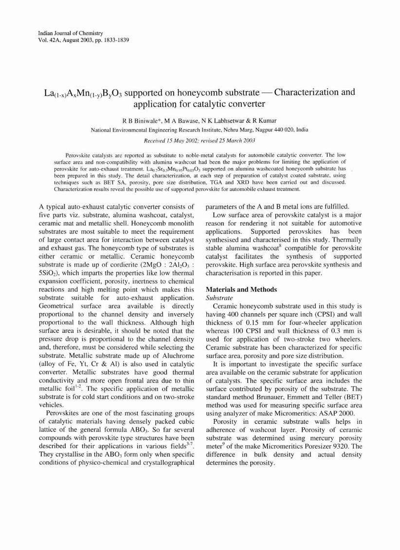
BET plot of ceramic substrate is depicted in Fig. I. The BET surface area and porosity of ceramic substrate, used in this study, was in the range of 0.6 to 1.0 m2/g and 30 per cent respectively. Though the ceramic substrate is having large geometrical surface area it offers very low specific surface area. It was observed from the pore size distribution that about 76% of pores are below 50 )lm with about 4% below I )lm diameter and 24% of particles are found to be in the range of 50 to 120 )lm diameter.
Particle size analysis of alumina slurry carried out reveals that the mean particle size i.e. value of d50 is
1.8
1.6
1.'1
1.2
::::- 1. 0 6-"0 .e 0.8 -< ~
0.6
0.4
0.2
o o 0.02 0.04 0.06 0.08 0.10 012 0. 14 0. 16 0.18 0.20 0.22
Relative Pressure (p/PO)
Fig. J- BET plot for ceramic substrate
1836 INDIAN J. CHEM. , SEC. A, AUGUST 2003
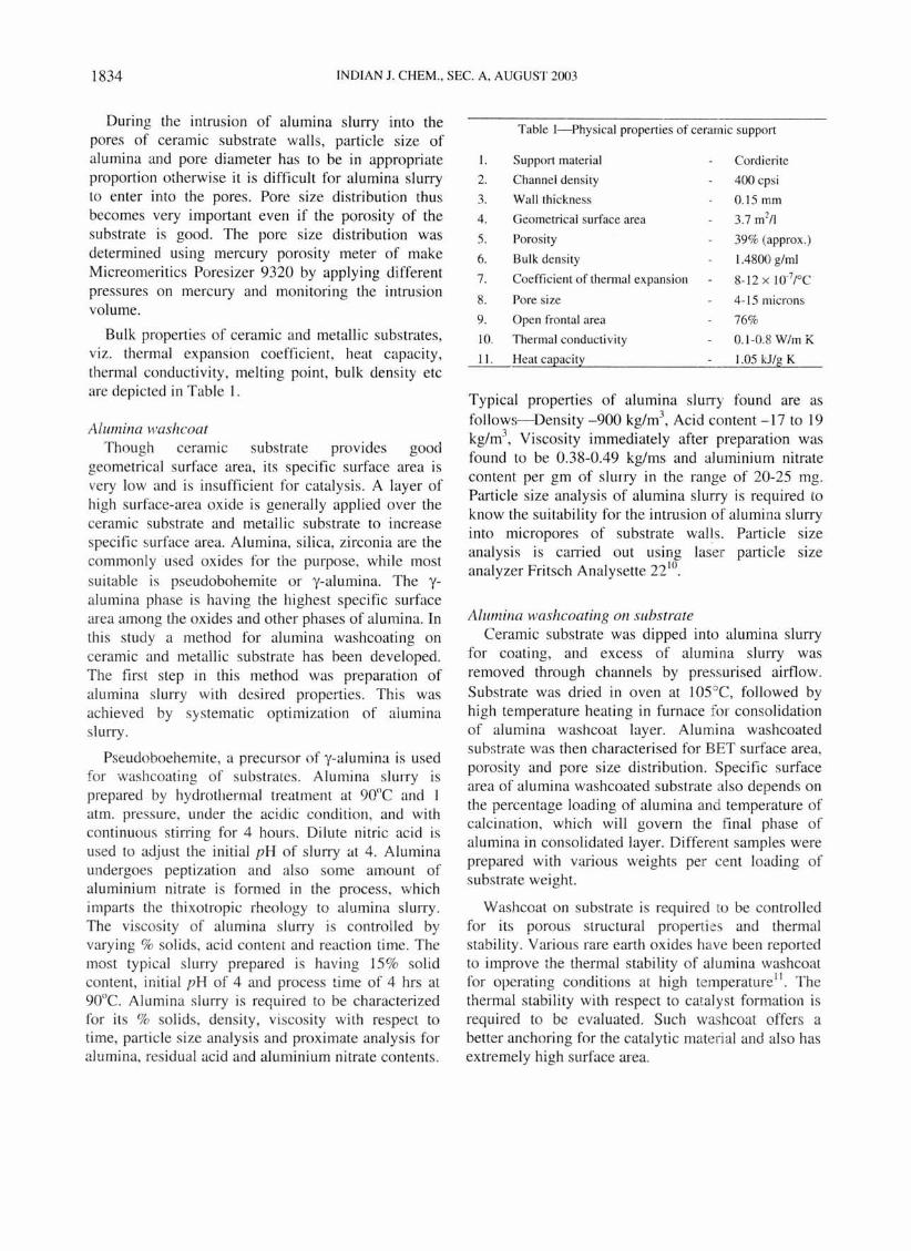
about 6 Ilm and dlO is about 2 Ilm. This particle size distribution is not suitable for intrusion of alumina slurry into the micropores of ceramic substrate walls. A mechanical grinding treatment was applied to alumina slurry in a high-speed blender for particle size reduction . Different methods have been employed for alumina slurry preparation such as variation in dispersibility of alumina and extent of mechanical treatment. Alumina slurry resulted from each method has been characterized for physicochemical analysis of alumina slurry. Particle size analysis of alumina slurry with thermomechanical treatment shows that the value of dso is 4.25 Ilm and d90 is about 15 Ilm and the value of dso and d90 for the high speed blender was found to be 1.39 and 3.0 Ilm respectively. Alumina slurry has shown thixotropic behavior and viscosity was observed to be changed with time and shear applied. Change in viscosity could pose a problem of channel blockage in coating process of honeycomb substrate. Variation in viscosity of alumina slurry was studied with varied extent of thermo-mechanical treatment followed by blender treatment against the standing
7,---------------------------------,
6
- :I
1 _ 4
2
Effter of hydrothermol treatment 1--3Hr
2_-1 Hr
o :I 10 1:1 20 2:1 30 3!) 40 4~ ~ ~~ 60 6~ 70
Slooding lim. (min.)
14.-------------------------------~
Ef1Kt of artriter treatment
12 1 • Omin 3
10 I( 2 • 10min
~ 8 3 • 20min
?-.~ 6
:> 4
2
o 20 40 60 80 100
Slanding II".. (min J
Fig. 2- Variation of viscosity with time
time. Fig. 2 shows the time dependent changes in viscosity with hydrothermal treatment and blender treatment respectively. It is evident that, with the extent of blender treatment to alumina slurry, along with the reduction in particle size, the rate of change of viscosity increases. Therefore it is necessary to optimize blender treatment to avoid the blockage problem during the alumina washcoating.
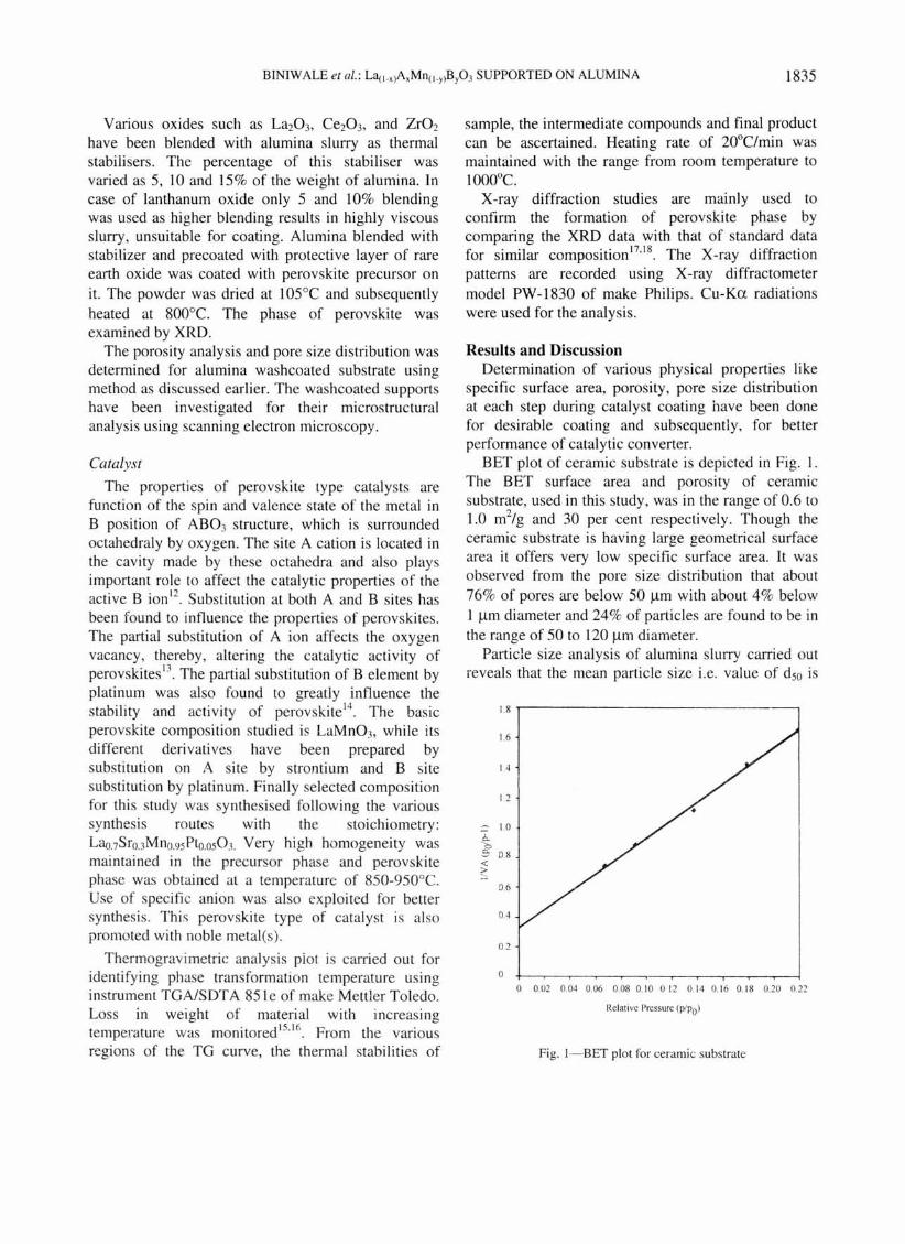
Specific surface area of alumina wash coated substrate with various percentages loading is shown in Fig. 3. Initially, specific surface area increases linearly with the percentage loading up to 35% loading value. It was also observed that more than 30% loading creates problem during air-kneifing, as the chances of cell blockage increases. The alumina loading is therefore maintained at 18-20% so as to get resultant specific surface area of about 25 m2/g and simultaneously maintaining large open frontal area and subsequently lower pressure drop .
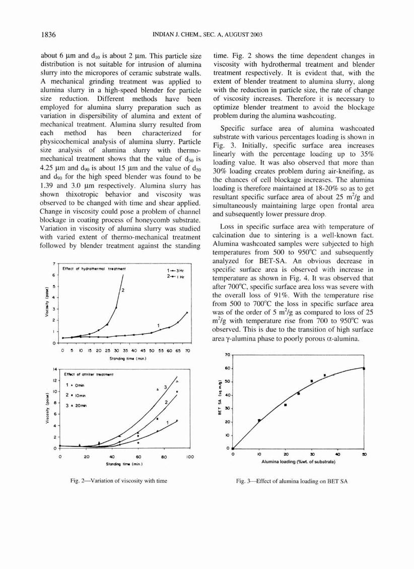
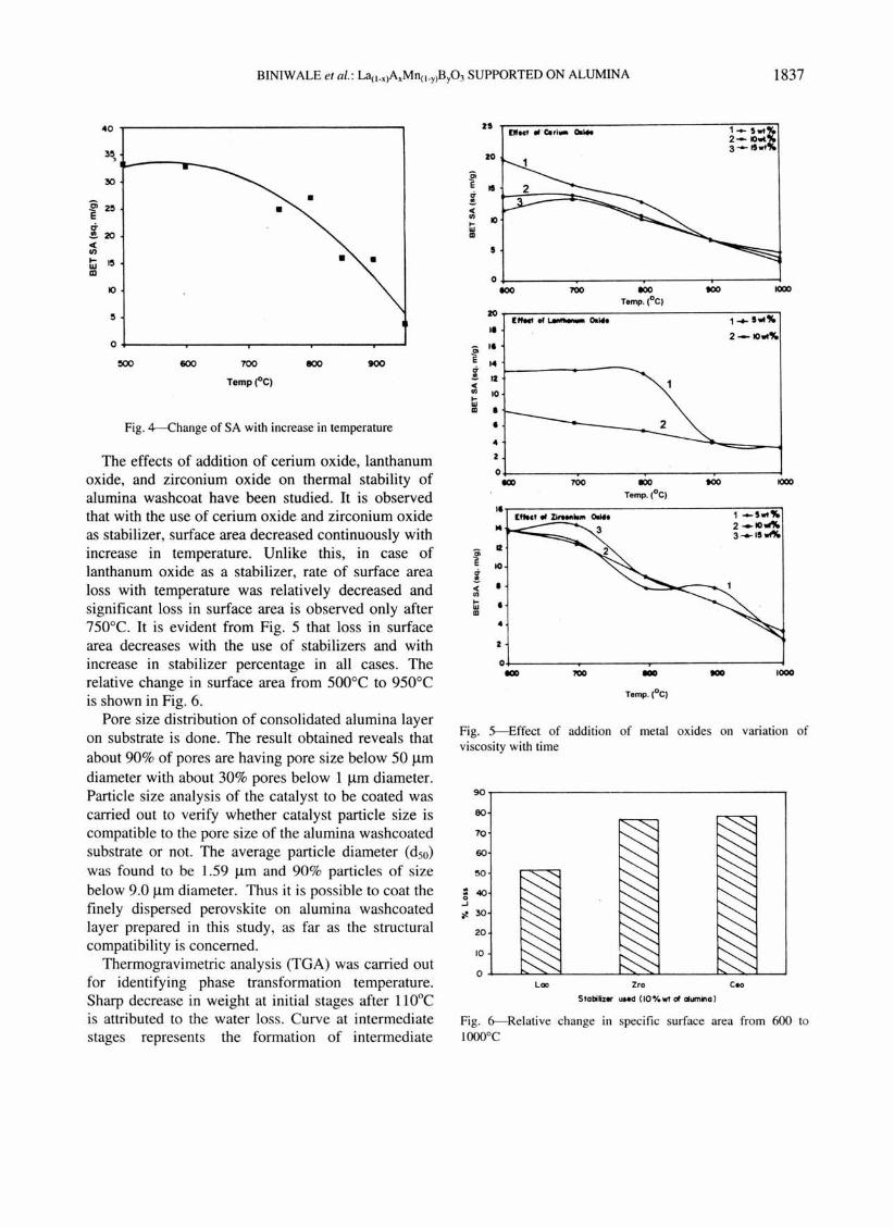
Loss in specific surface area with temperature of calcination due to sintering is a well-known fact. Alumina washcoated samples were s bjected to high temperatures from 500 to 950°C and subsequently analyzed for BET-SA. An obvious decrease in specific surface area is observed wi th increase in temperature as shown in Fig. 4. It was observed that after 700°C, specific surface area loss was severe with the overall loss of 91 %. With the temperature rise from 500 to 700°C the loss in specific surface area was of the order of 5 m2/g as compared to loss of 25 m2/g with temperature rise from 700 to 950°C was observed. This is due to the transition of high surface area y-alumina phase to poorly porous a-alumina.
70
60
~ :10 E ~ 40 ... V>
~ 30 .., III
20
10
0
0
Alumina loading ('!owt. of substrate)
Fig. 3--Effect of alumina loading on BET SA
BINIWALE et ai. : La(l .• )A.Mn(l .y)ByOJ SUPPORTED ON ALUMINA 1837
40
3!1 ,
30
~ 2!1 E r:T .!.zo c( Ul ~ e w CD
10
!I
0
!500
Fig. 4-Change of SA with increase in temperature
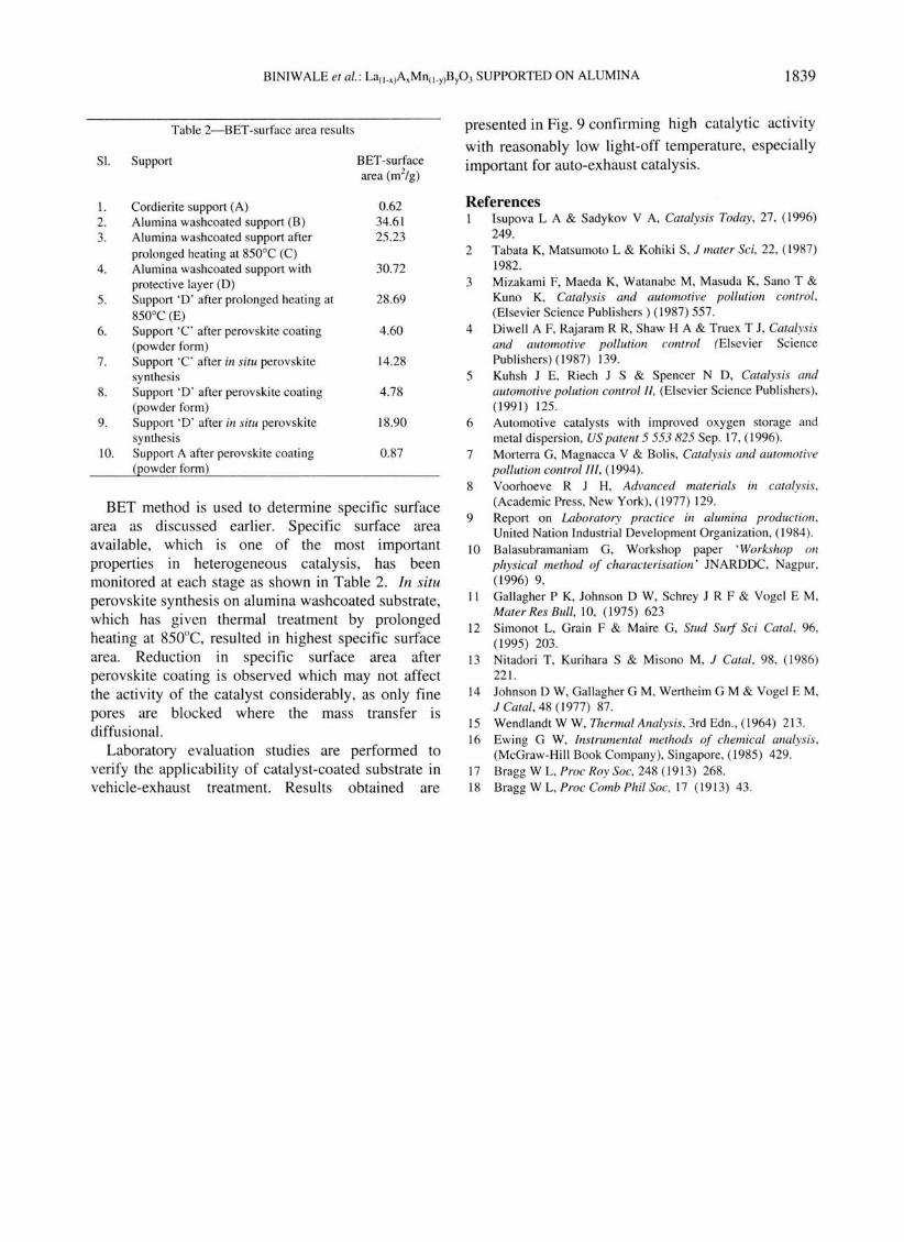
The effects of addition of cerium oxide, lanthanum oxide, and zirconium oxide on thermal stability of alumina washcoat have been studied. It is observed that with the use of cerium oxide and zirconium oxide as stabilizer, surface area decreased continuously with increase in temperature. Unlike this, in case of lanthanum oxide as a stabilizer, rate of surface area loss with temperature was relatively decreased and significant loss in surface area is observed only after 7S0°C. It is evident from Fig. S that loss in surface area decreases with the use of stabilizers and with increase in stabilizer percentage in all cases. The relative change in surface area from SOO°C to 9S0°C is shown in Fig. 6.
Pore size distribution of consolidated alumina layer on substrate is done. The result obtained reveals that about 90% of pores are having pore size below SO Ilm diameter with about 30% pores below 1 Ilm diameter. Particle size analysis of the catalyst to be coated was carried out to verify whether catalyst particle size is compatible to the pore size of the alumina washcoated substrate or not. The average particle diameter (dso)
was found to be 1.S9 Ilm and 90% particles of size below 9.0 Ilm diameter. Thus it is possible to coat the finely dispersed perovskite on alumina washcoated layer prepared in this study, as far as the structural compatibility is concerned.
Thermogravimetric analysis (TGA) was carried out for identifying phase transformation temperature. Sharp decrease in weight at initial stages after 110°C is attributed to the water loss. Curve at intermediate stages represents the formation of intermediate
n Ooct " ·C.,I. 00 ...
zo
f r7
II
~ « II)
10 >-OJ III
I
0 toO 100 toO
Temp. (0C)
ZO l_"~o.",.
II
f II
r7 14 ~ __ - __ ---......
~ 12 « ~ 10 OJ III •
• 4
Z
1_5 .. %. 2- IOwt%. 3'" IS .. %.
tOO 1000
1-+"'%.
2 -IO",%.
O~ ___ ~ ___ ~ _____ ~ ___ ~
~ E
! « II)
>-OJ III
IOD 100 100 toO 1000
II
14
II
10
• I
4
Z
0
Temp. (0C)
llloc' .. z;,.. .... 0014.
ICIO toO
1 _5 .. %. 2_1O~ 3 · ..... 15...".
1000
Fig. 5---Effect of addition of metal oxides on variation of viscosity with time
90r----------------------------, eo
70
60
20
10
Lao Zro Coo
510mb .. us.d (10"1 ... at alumino)
Fig. 6--Relative change in specific surface area from 600 to lOOO°C

1838
' . ............
INDIAN J. CHEM .• SEC. A. AUGUST 2003
compou nds and phase formation temperature of the perovskite catalyst has been found to be between 850 and 950°C. TGA analysis of the catalyst is shown in Fig. 7.
......... ... '" , ,
~ .: "'/ \/
i ii
200 400
Fig. 7- Thermogravimetric composition
100
10
~ :>. u eo c:
" 'u :: w c:
° 40 'f " > c:
° u 20
0
I I
600 i
800
analysis (TGA) of perovskite
The XRD data have been compared wi th that of the standard data (Joint Committee on Powder Diffraction Standards (JCPDS) Cards) of the simi lar perovskite compositions. The prominent d-lines of the patterns have been found to be in agreement with standard dlines establishing perovskite phase formation . XRD plot of perovskite catalyst is shown in Fig, 8. The catalyst shows perovskite structure with a few distortions.
200
10 ... ~ 20 30 ~ ~o 4 , ~4 Z,U 2.25 1.12
Two Theta (dev) I d-~
110 1· 54
Fig. 8--A typical XRD pattern of perovskite composition
Space velocity 80,000 hr-I • •
3
2~0 XlO ~ 400 ,,~o ~ 550
Temperature (0C)
2 1
1 .eo
70 1·34
2 • He
3 .NO~
100 150
Fig. 9--Laboratory eval uation results for perovskite coated ceramic substrate
BINIWALE et 01.: La(l .,)A,Mn(l .y)By03 SUPPORTED ON ALUMINA 1839
Table 2-BET-surface area results
SI. Support BET -surface area (m2/g)
I. Cordierite support (A) 0.62 2. Alumina washcoated support (B) 34.6 1 3. Al umina wash coated support after 25.23
prolonged heating at 850°C (C) 4. Alumina washcoated support with 30.72
protective layer (D) 5. Support '0 ' after prolonged heating at 28.69
850°C (E) 6. Support 'C' after perovskite coating 4.60
(powder form) 7. Support 'C' after in situ perovskite 14.28
synthesis 8. Support '0' after perovskite coat ing 4.78
(powder form) 9. Support '0' after ill situ perovskite 18.90
sy nthesis 10. Support A after perovskite coating 0.87
(powder fo rm)
BET method is used to determine specific surface area as discussed earlier. Specific surface area available, which is one of the most importan t properties in heterogeneous catalysis, has been monitored at each stage as shown in Table 2. In situ perovskite synthesis on alumina washcoated substrate, which has given thermal treatment by prolonged heating at 850°C, resulted in highest specific surface area. Reduction in specific surface area after perovskite coating is observed which may not affect the activi ty of the catalyst considerably, as only fine pores are blocked where the mass transfer IS
diffusional. Laboratory evaluation studies are performed to
verify the applicability of catalyst-coated substrate in vehicle-exhaust treatment. Results obtained are
presented in Fig. 9 confirming high catalytic activity
with reasonably low light-off temperature, especiall y important for auto-exhaust catalysis.
References I Isupova L A & Sadykov V A, Catalysis Today , 27, (1996)
249. 2 Tabata K, Matsumoto L & Kohiki S, J mater Sci, 22, ( 1987)
1982. 3 Mizakami F, Maeda K, Watanabe M, Masuda K, Sano T &
Kuno K, Catalysis alld automotive pollution COlltrol, (Elsevier Science Publishers) (1987) 557.
4 Diwell A F, Rajaram R R, Shaw H A & Truex T J, Catalysis alld automotive poilution. cOllIrol (Elsevier Science Publishers) (1987) 139.
5 Kuhsh J E, Riech J S & Spencer N 0 , Catalysis alld automotive polution control II, (Elsevier Science Publi shers), (1991) 125.
6 Automotive catalysts with improved oxygen storage and metal dispersion, US patelll 5 553 825 Sep. 17, ( 1996).
7 Morterra G, Magnacca V & Bolis, Catalysis and automotive pollutioll control Ill, (1994).
8 Voorhoeve R J H, Advanced materials ill catalysis, (Academic Press, New York), ( 1977) 129.
9 Report on Laboratory practice in alumina production, United Nation Industrial Development Organization, ( 1984).
10 Balasubramaniam G, Workshop paper 'Workshop on physical method of characterisation ' JNARDDC, Nagpur, (1996) 9.
II Gal lagher P K, Johnson 0 W, Schrey J R F & Vogel E M, Mater Res Bull, 10, (1975) 623
12 Simonot L, Grain F & Maire G, Stud Surf Sci Catal, 96, (1995) 203.
13 Nitadori T, Kurihara S & Misono M, J Catal , 98, (1986) 22 1.
14 Johnson 0 W, Gallagher G M, Wertheim G M & Vogel EM, J Catal, 48 ( 1977) 87.
15 Wendlandt W W, Thermal Analysis, 3rd Edn., (1964) 213 . 16 Ewing G W, Instrumental methods of chemical analysis,
(McGraw-Hili Book Company), Singapore, (1985) 429. 17 Bragg W L, Proc Roy Soc, 248 (19 13) 268. 18 Bragg W L, Proc Comb Phil Soc, 17 (19 13) 43 .