Embed Size (px)
Citation preview
LADOTD BRIDGE DESIGN AND EVALUATION MANUAL (BDEM)
Louisiana Transportation Conference
2/29/2016
Zhengzheng “Jenny” Fu, P.E.
Assistant Bridge Design Administrator LADOTD Bridge Design Section
1

ACKNOWLEDGEMENTS
DOTD Staff
FHWA
Consultants
SDR Engineering Consultants, Inc. (Prime)
Huval and Associates (Sub)
All Users
2
OUTLINE
3
Overview of BDEM
Overview of BDTM.50
Highlights of BDEM Part II – Design Specifications
BDEM
Published on 11/17/2014 via BDTM.50
Posted on Bridge Design Website
4

BRIDGE DESIGN WEBSITE http://wwwsp.dotd.la.gov/Pages/default.aspx
5
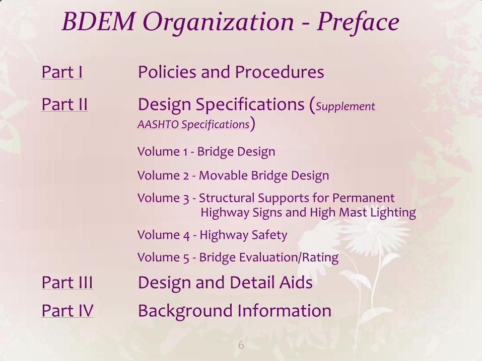
BDEM Organization - Preface
Part I Policies and Procedures
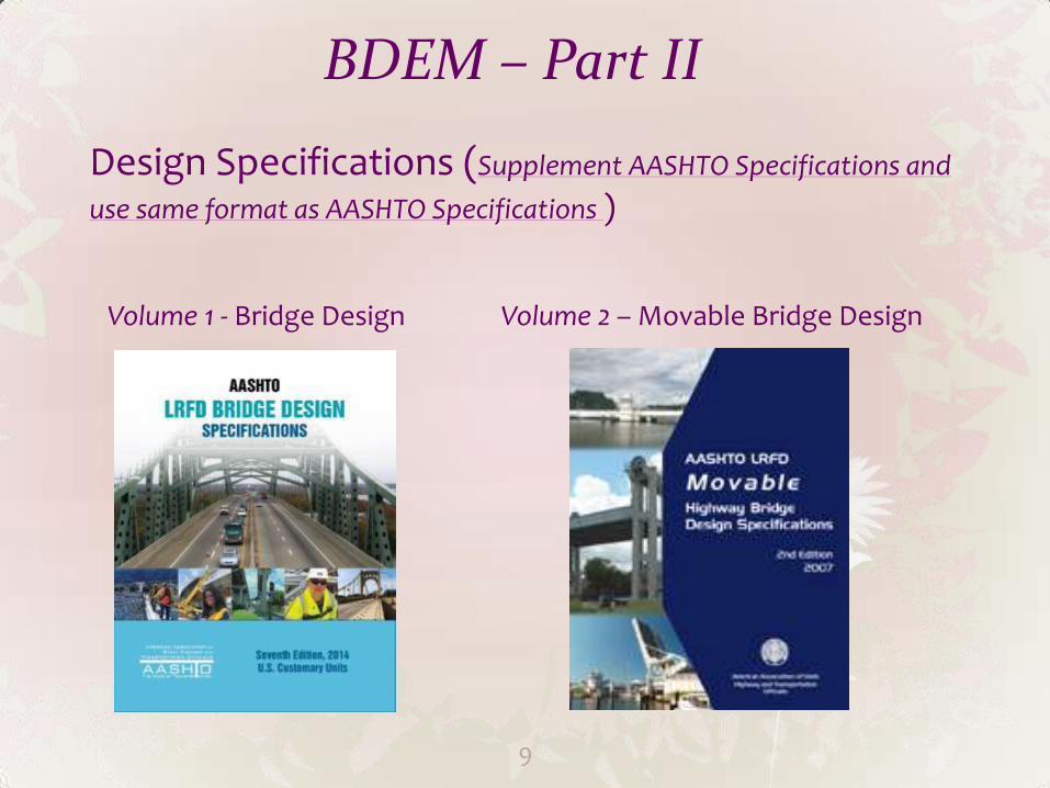
Part II Design Specifications (Supplement
AASHTO Specifications)
Volume 1 - Bridge Design
Volume 2 - Movable Bridge Design
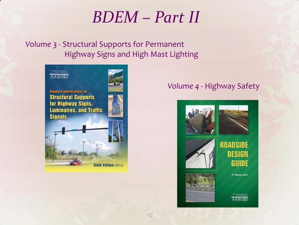
Volume 3 - Structural Supports for Permanent Highway Signs and High Mast Lighting
Volume 4 - Highway Safety
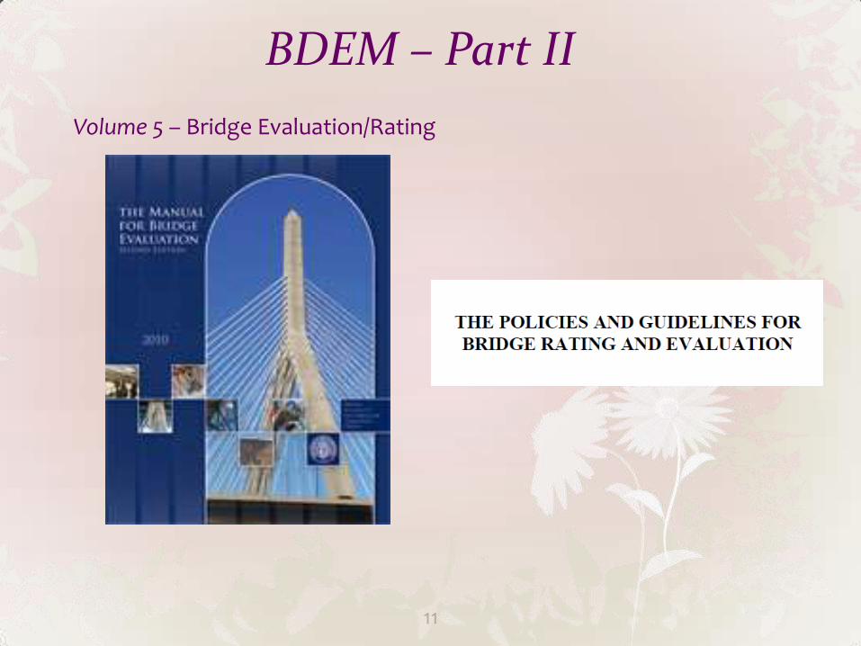
Volume 5 - Bridge Evaluation/Rating
Part III Design and Detail Aids
Part IV Background Information
6

BDEM Revision History
7
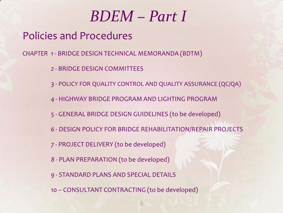
BDEM – Part I Policies and Procedures
CHAPTER 1 - BRIDGE DESIGN TECHNICAL MEMORANDA (BDTM)
2 - BRIDGE DESIGN COMMITTEES
3 - POLICY FOR QUALITY CONTROL AND QUALITY ASSURANCE (QC/QA)
4 - HIGHWAY BRIDGE PROGRAM AND LIGHTING PROGRAM
5 - GENERAL BRIDGE DESIGN GUIDELINES (to be developed)
6 - DESIGN POLICY FOR BRIDGE REHABILITATION/REPAIR PROJECTS
7 - PROJECT DELIVERY (to be developed)
8 - PLAN PREPARATION (to be developed)
9 - STANDARD PLANS AND SPECIAL DETAILS
10 – CONSULTANT CONTRACTING (to be developed)
8
BDEM – Part II
Design Specifications (Supplement AASHTO Specifications and
use same format as AASHTO Specifications )
Volume 1 - Bridge Design Volume 2 – Movable Bridge Design
9
BDEM – Part II
Volume 3 - Structural Supports for Permanent Highway Signs and High Mast Lighting
Volume 4 - Highway Safety
10
BDEM – Part II
Volume 5 – Bridge Evaluation/Rating
11
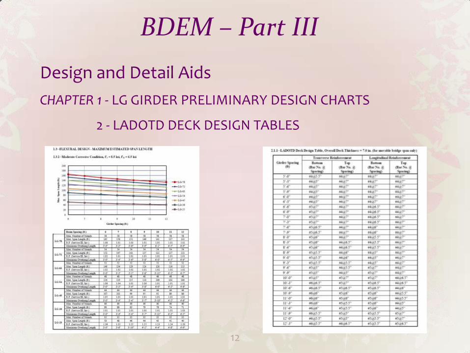
BDEM – Part III
Design and Detail Aids
CHAPTER 1 - LG GIRDER PRELIMINARY DESIGN CHARTS
2 - LADOTD DECK DESIGN TABLES
12
BDEM – Part IV
Background Information
CHAPTER 1 - LADV-11 DEVELOPMENT
2 - TEMPERATURE RANGE STUDY
13
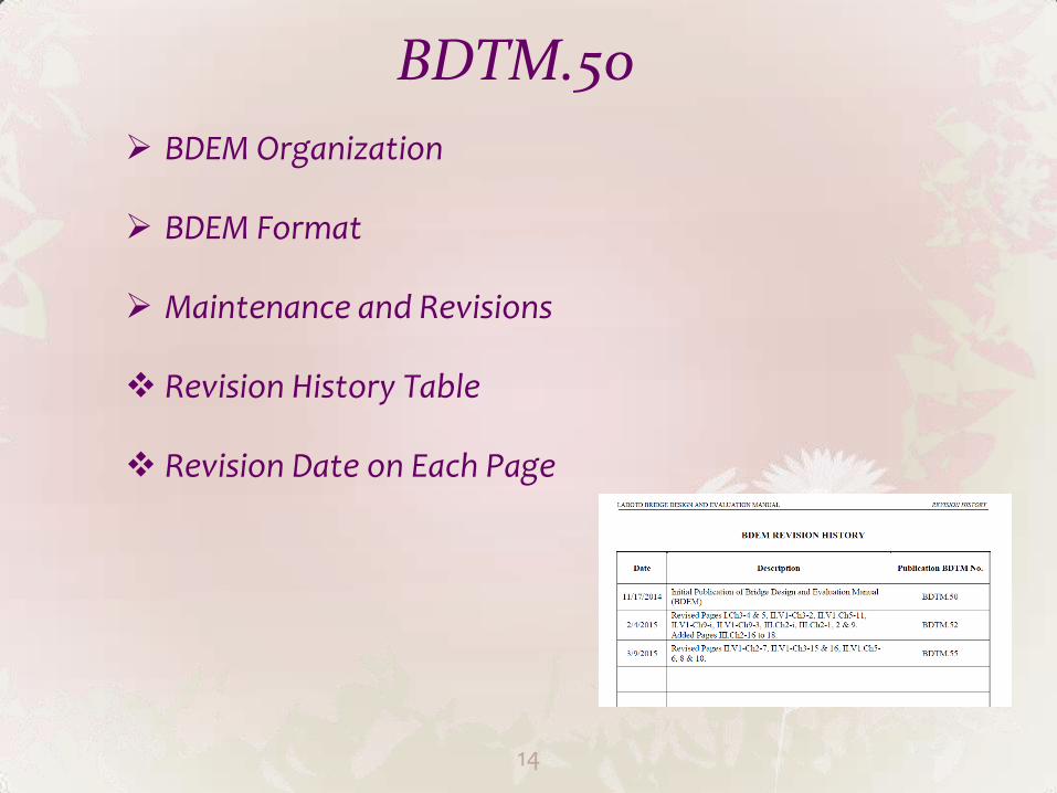
BDTM.50
BDEM Organization
BDEM Format
Maintenance and Revisions
Revision History Table
Revision Date on Each Page
14
BDTM.50
15
Consultant Projects
Revisions before NTP - Implement
Revisions after NTP – Implement if no impact to scope and schedule; implement with approval if impact scope and schedule
In-House Projects (similar to Consultant Projects)
New AASHTO Editions or Interims
Implement via BDTM
BDTM.50
16
Archived Manuals
Bridge Design English Manual (4th Edition)
Bridge Design Metric Manual
LRFD Bridge Design Manual
BDEM Archived Pages
Guidelines – Part of BDEM
Federal Aid Off-System Highway Bridge Program Guidelines
(Referenced in Part I, Chapter 4, Stand-Alone document )
Guide to Constructing, Operating, and Maintaining Highway Lighting System
(Referenced in Part I, Chapter 4, Stand-Alone document)
Policies and Guidelines for Bridge Rating and Evaluation
(Referenced in Part II, Volume 5, will be incorporated to BDEM)
BDTM.50
17
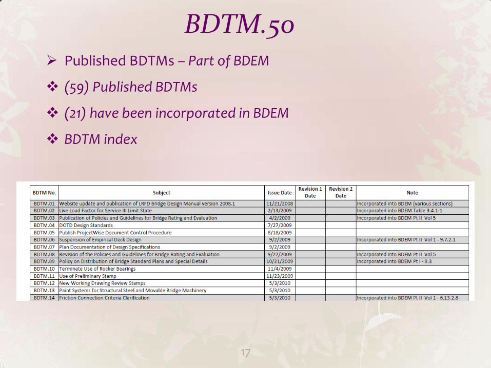
Published BDTMs – Part of BDEM
(59) Published BDTMs
(21) have been incorporated in BDEM
BDTM index
BDEM Highlights Part II, Vol. 1 – Bridge Design
Chapter 1 - Introductions
1.1 – Bridges vulnerable to coastal storms
Construction Specifications
1.2 – New definitions
1.3 – Ductility, Redundancy, Operational Importance factors
18
BDEM Highlights Part II, Vol. 1 – Bridge Design
Chapter 2 - General Design and Location Features
2.2 New definitions
2.3.2.2 Traffic Safety (User and Structure Protections)
EDSMs - Guard Rails, Curbs, Sidewalks
Bridge Railings – Min. TL-4 (NCHRP 350 or MASH)
Sidewalks – ADA Standards, Min. 5’-0” Pedestrian, 6’-0” Bicycle
Geometric Stds – Min. Design Guidelines signed by Chief Engineer
EDSMs - R/W, SSD on Curve Bridges
Road Surface Slopes – Min. 2.5%
Vessel Collision Protections
19
BDEM Highlights Part II, Vol. 1 – Bridge Design
Chapter 2 - General Design and Location Features
2.3.3 Clearances
Navigational, Highway Vertical and Horizontal, R/R Overpass
2.5.2.2 Inspectability
Design requirements and details for maintenance and inspection purpose
2.5.2.3 Maintainability
Min. vertical and horizontal clearances for bearing
maintenance and repair/replacement
20
BDEM Highlights Part II, Vol. 1 – Bridge Design
Chapter 2 - General Design and Location Features
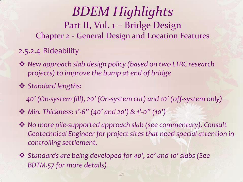
2.5.2.4 Rideability
New approach slab design policy (based on two LTRC research projects) to improve the bump at end of bridge
Standard lengths:
40’ (On-system fill), 20’ (On-system cut) and 10’ (off-system only)
Min. Thickness: 1’-6” (40’ and 20’) & 1’-0” (10’)
No more pile-supported approach slab (see commentary). Consult Geotechnical Engineer for project sites that need special attention in controlling settlement.
Standards are being developed for 40’, 20’ and 10’ slabs (See
BDTM.57 for more details) 21
BDEM Highlights Part II, Vol. 1 – Bridge Design
Chapter 2 - General Design and Location Features
2.5.5 Bridge Aesthetics
Emphasize the importance of bridge aesthetics and implementation of Context Sensitive Solutions (CSS)
2.6.6 Roadway Drainage
Deck drainage requirements
22
BDEM Highlights Part II, Vol. 1 – Bridge Design Chapter 3 - Load and Load Factors
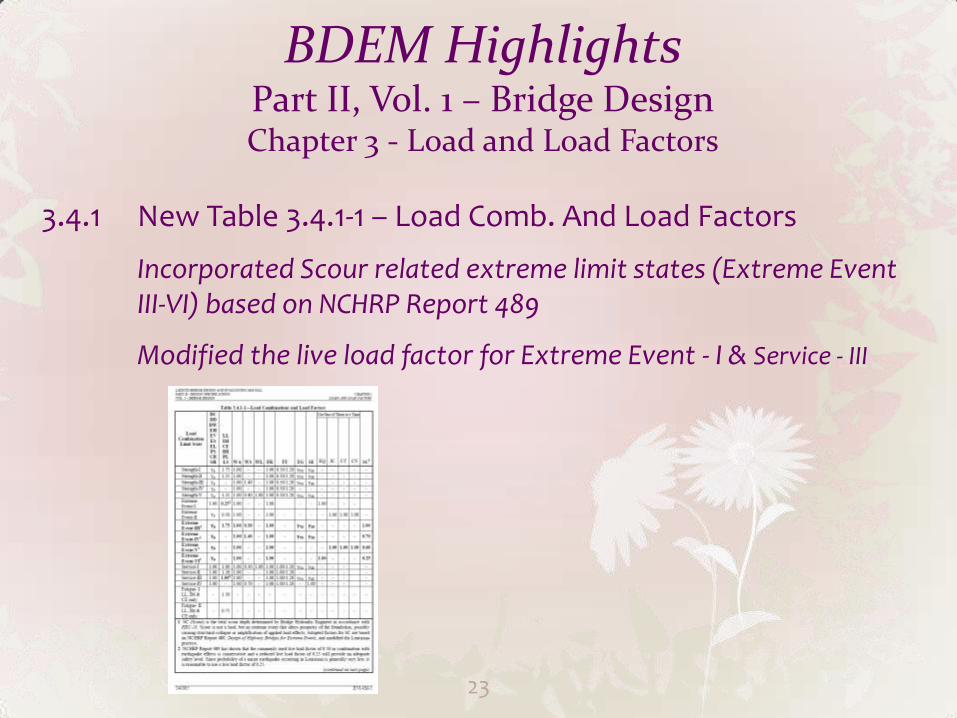
3.4.1 New Table 3.4.1-1 – Load Comb. And Load Factors
Incorporated Scour related extreme limit states (Extreme Event III-VI) based on NCHRP Report 489
Modified the live load factor for Extreme Event - I & Service - III
23
BDEM Highlights Part II, Vol. 1 – Bridge Design Chapter 3 - Load and Load Factors
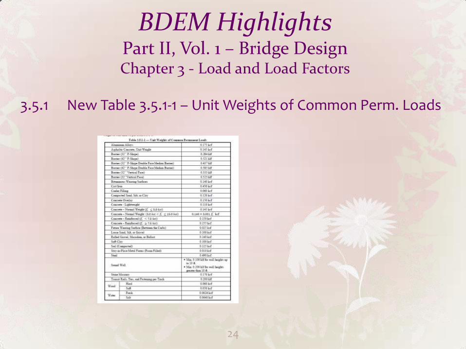
3.5.1 New Table 3.5.1-1 – Unit Weights of Common Perm. Loads
24
BDEM Highlights Part II, Vol. 1 – Bridge Design Chapter 3 - Load and Load Factors
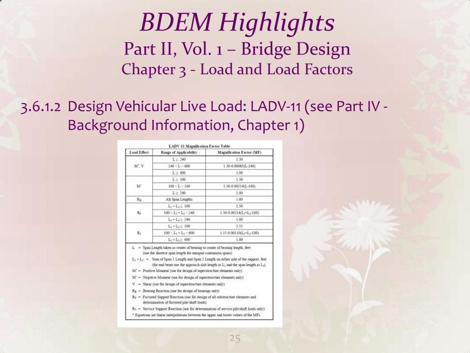
3.6.1.2 Design Vehicular Live Load: LADV-11 (see Part IV - Background Information, Chapter 1)
25
BDEM Highlights Part II, Vol. 1 – Bridge Design Chapter 3 - Load and Load Factors
C3.6.1.4.2 Typical example of determining ADTTSL over design life for Fatigue Load
3.6.4 Braking Forces –BR
Apply BR to substructure and bearing design
26
BDEM Highlights Part II, Vol. 1 – Bridge Design Chapter 3 - Load and Load Factors
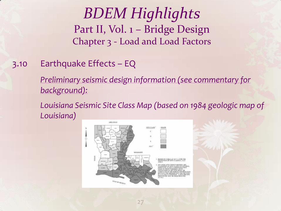
3.10 Earthquake Effects – EQ
Preliminary seismic design information (see commentary for background):
Louisiana Seismic Site Class Map (based on 1984 geologic map of Louisiana)
27
BDEM Highlights Part II, Vol. 1 – Bridge Design Chapter 3 - Load and Load Factors
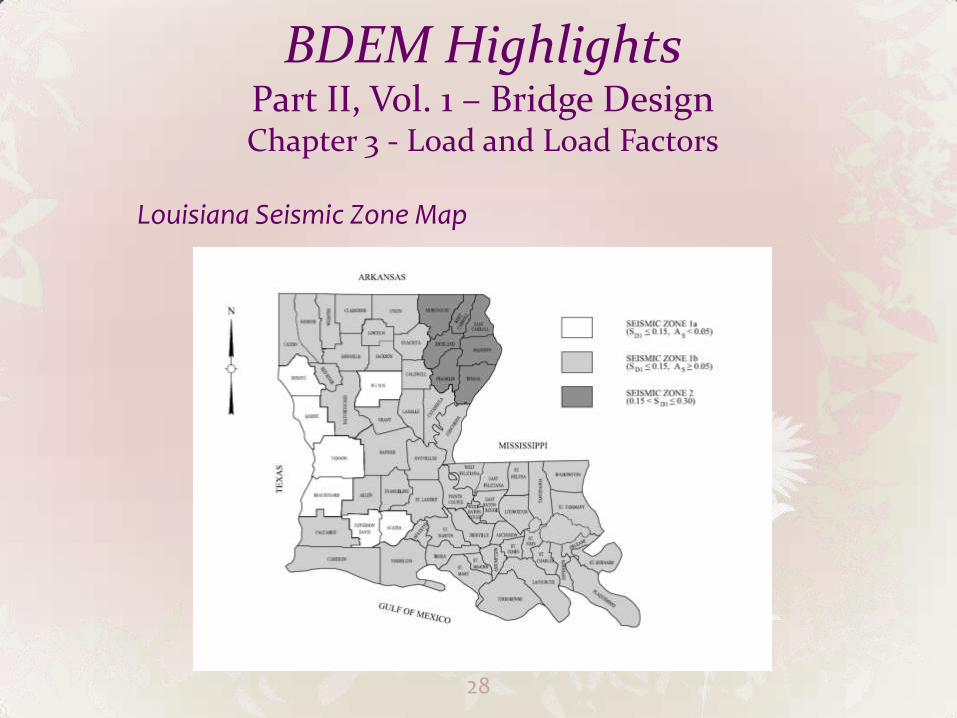
Louisiana Seismic Zone Map
28
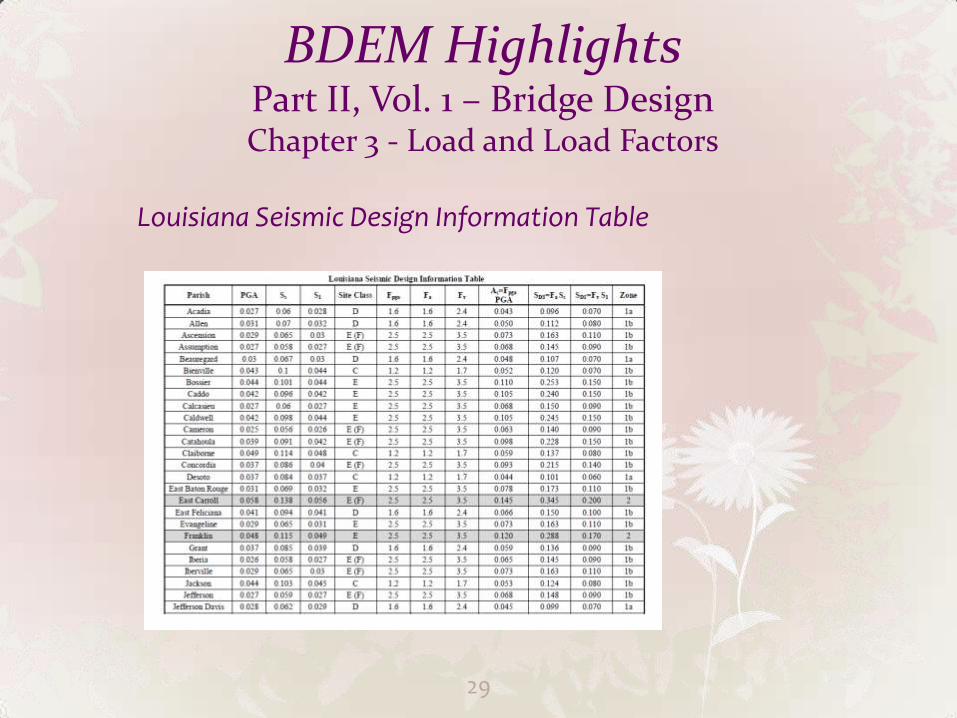
BDEM Highlights Part II, Vol. 1 – Bridge Design Chapter 3 - Load and Load Factors
Louisiana Seismic Design Information Table
29
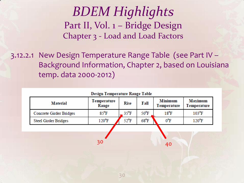
BDEM Highlights Part II, Vol. 1 – Bridge Design Chapter 3 - Load and Load Factors
3.12.2.1 New Design Temperature Range Table (see Part IV – Background Information, Chapter 2, based on Louisiana temp. data 2000-2012)
30
30 40
BDEM Highlights Part II, Vol. 1 – Bridge Design Chapter 3 - Load and Load Factors
3.14.1 Two Vessel Collision Events Defined for Extreme II and V
A Drifting Empty Barge
A Ship or Barge Tow under Normal Operation
31
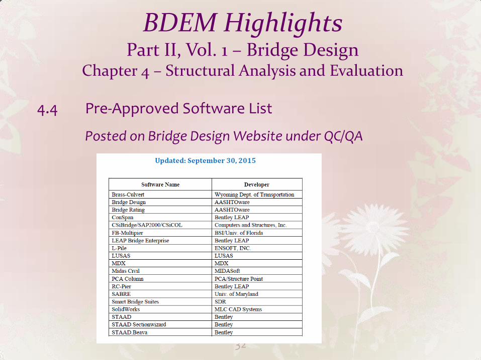
BDEM Highlights Part II, Vol. 1 – Bridge Design
Chapter 4 – Structural Analysis and Evaluation
4.4 Pre-Approved Software List
Posted on Bridge Design Website under QC/QA
32
BDEM Highlights Part II, Vol. 1 – Bridge Design Chapter 5 - Concrete Structures
5.4.3 Reinforcing Steel
Uncoated “black” bar, Grade 60, Grade 75 allowed for WWF only
Epoxy coated reinforcing not allowed
Requires approval for any type other than “black” bar
5.4.4 Prestressing Steel
0.6 in (preferred) and 0.5 in dia.
Grade 270 low relaxation bar (Stress-Relieved strand not allowed)
33
BDEM Highlights Part II, Vol. 1 – Bridge Design Chapter 5 - Concrete Structures
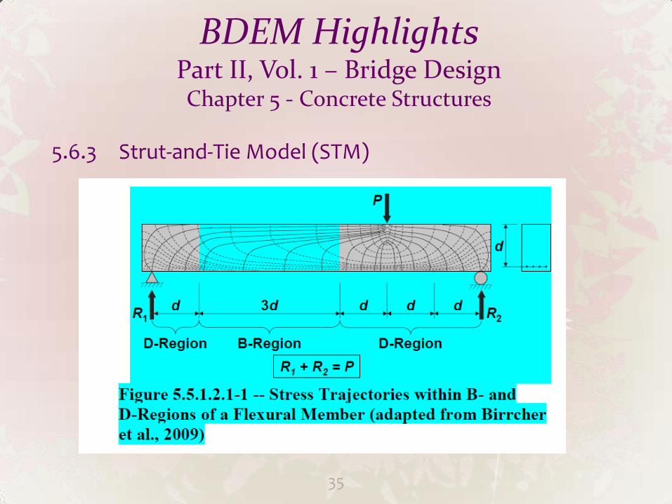
5.6.3 Strut-and-Tie Model (STM)
STM should be used for situations that conventional beam theory does not apply.
Examples: deep beams, deep footings, hammerhead caps, near supports of pile and column bent caps, ends of
beams, etc.
34
BDEM Highlights Part II, Vol. 1 – Bridge Design Chapter 5 - Concrete Structures
5.6.3 Strut-and-Tie Model (STM)
35
BDEM Highlights Part II, Vol. 1 – Bridge Design Chapter 5 - Concrete Structures
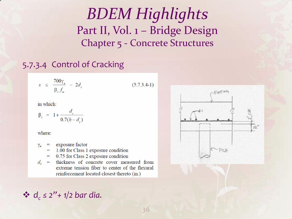
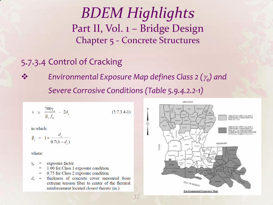
5.7.3.4 Control of Cracking
dc ≤ 2”+ 1/2 bar dia.
36
BDEM Highlights Part II, Vol. 1 – Bridge Design Chapter 5 - Concrete Structures
5.7.3.4 Control of Cracking
Environmental Exposure Map defines Class 2 (e) and
Severe Corrosive Conditions (Table 5.9.4.2.2-1)
37
BDEM Highlights Part II, Vol. 1 – Bridge Design Chapter 5 - Concrete Structures
5.7.3.6.2 Deflection and Camber
Adopted PCI multiplier method
5.8.2.7 Maximum Spacing of Trans. Reinforcement Max. 12” for girders span existing or future traffic
lanes or R/R track and bent caps
5.8.3.4 Procedures for Determining Shear Resistance
Simplified Procedure 5.8.3.4.1 (=2, =45) allowed
General Procedure 5.8.3.4.2 (MCFT) allowed
Simplified Procedure 5.8.3.4.3 (Vci and Vcw) not allowed
38
BDEM Highlights Part II, Vol. 1 – Bridge Design Chapter 5 - Concrete Structures
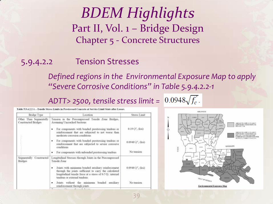
5.9.4.2.2 Tension Stresses
Defined regions in the Environmental Exposure Map to apply “Severe Corrosive Conditions” in Table 5.9.4.2.2-1
ADTT> 2500, tensile stress limit =
39
BDEM Highlights Part II, Vol. 1 – Bridge Design Chapter 5 - Concrete Structures
5.12 Durability
LADOTD Strategy:
HPC with surface resistivity requirement (New Specifications)
Min. Concrete Cover (5.12.3)
Crack control (5.7.3.4)
14 days of water curing (New Specifications)
40
BDEM Highlights Part II, Vol. 1 – Bridge Design Chapter 5 - Concrete Structures
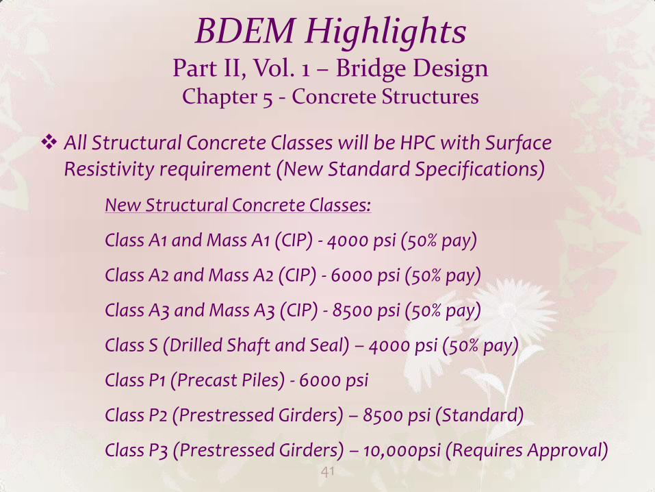
All Structural Concrete Classes will be HPC with Surface
Resistivity requirement (New Standard Specifications)
New Structural Concrete Classes:
Class A1 and Mass A1 (CIP) - 4000 psi (50% pay)
Class A2 and Mass A2 (CIP) - 6000 psi (50% pay)
Class A3 and Mass A3 (CIP) - 8500 psi (50% pay)
Class S (Drilled Shaft and Seal) – 4000 psi (50% pay)
Class P1 (Precast Piles) - 6000 psi
Class P2 (Prestressed Girders) – 8500 psi (Standard)
Class P3 (Prestressed Girders) – 10,000psi (Requires Approval) 41
BDEM Highlights Part II, Vol. 1 – Bridge Design Chapter 5 - Concrete Structures
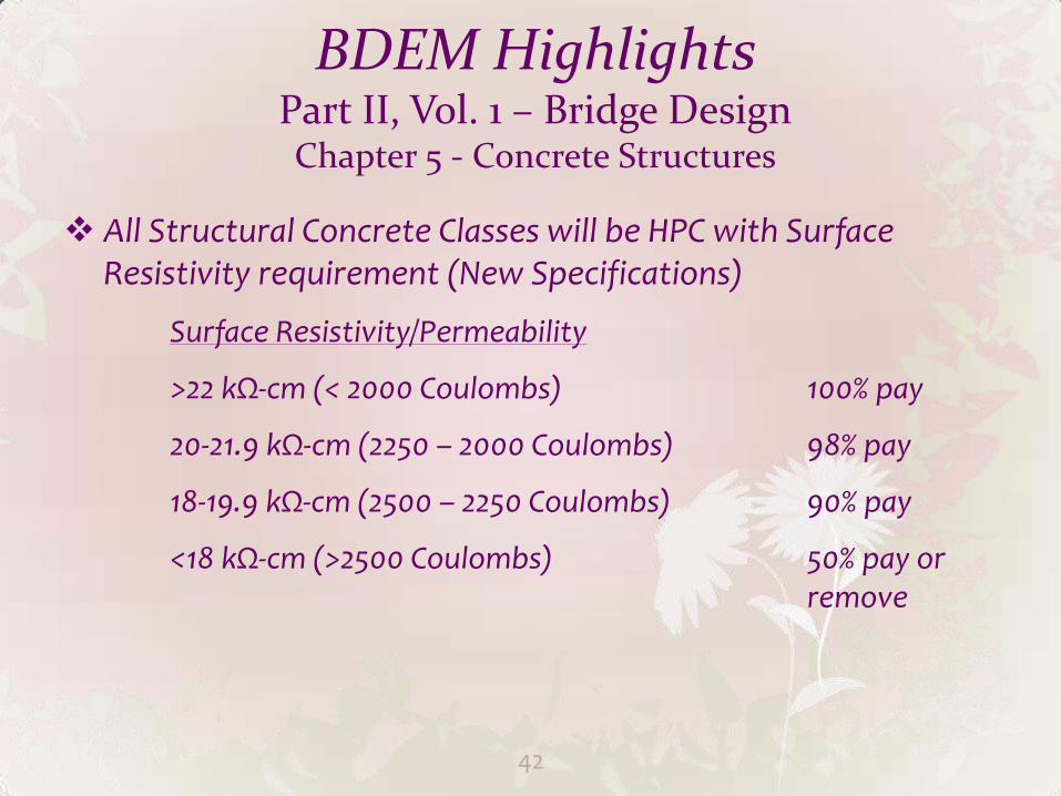
All Structural Concrete Classes will be HPC with Surface
Resistivity requirement (New Specifications)
Surface Resistivity/Permeability
>22 kΩ-cm (< 2000 Coulombs) 100% pay
20-21.9 kΩ-cm (2250 – 2000 Coulombs) 98% pay
18-19.9 kΩ-cm (2500 – 2250 Coulombs) 90% pay
<18 kΩ-cm (>2500 Coulombs) 50% pay or remove
42
BDEM Highlights Part II, Vol. 1 – Bridge Design Chapter 5 - Concrete Structures
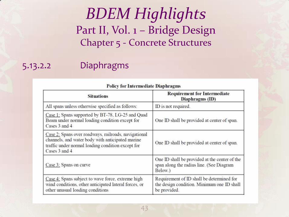
5.13.2.2 Diaphragms
43
BDEM Highlights Part II, Vol. 1 – Bridge Design Chapter 5 - Concrete Structures
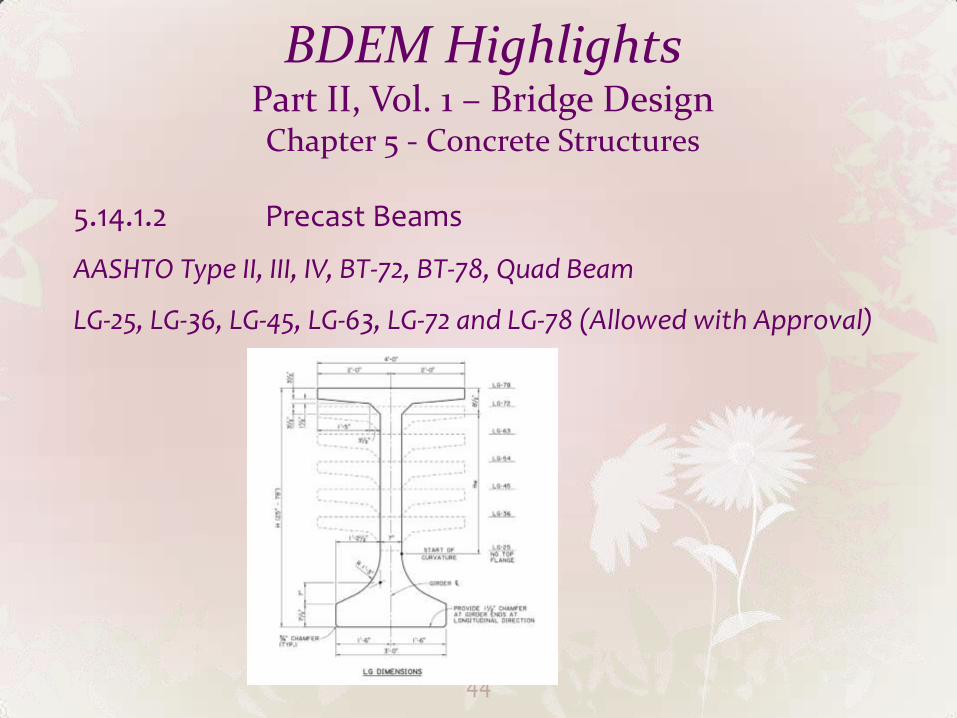
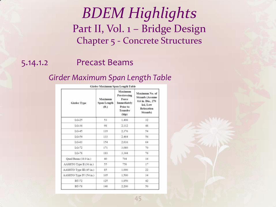
5.14.1.2 Precast Beams
AASHTO Type II, III, IV, BT-72, BT-78, Quad Beam
LG-25, LG-36, LG-45, LG-63, LG-72 and LG-78 (Allowed with Approval)
44
BDEM Highlights Part II, Vol. 1 – Bridge Design Chapter 5 - Concrete Structures
5.14.1.2 Precast Beams
Girder Maximum Span Length Table
45
BDEM Highlights Part II, Vol. 1 – Bridge Design Chapter 5 - Concrete Structures
5.14.1.2 Precast Beams
LG Girder Preliminary Design Tables – Part III, Chapter 1
Haunch Thickness
Limitation on using PPC girders in curved bridges
46
BDEM Highlights Part II, Vol. 1 – Bridge Design Chapter 5 - Concrete Structures
5.14.1.2 Precast Beams
Girder Stability Notes must be included in contract plans:
Contractor is responsible for stability of girders
Contractor is required to submit calculations and shop drawings to show all details for storage (dunnage), transportation, lifting and erection
EOR’s responsibility on girder stability during design process:
Ensure girders can be supported on dunnage within 3 feet from ends
Determine if the girders can be picked up in accordance with PCI Bridge Design Manual (follow the lateral stability example in PCI Manual)
Review Contractor’s calculations and shop drawings to ensure the proposed girder stability can be achieved within the allowable stress limits
47
BDEM Highlights Part II, Vol. 1 – Bridge Design
Chapter 6 – Steel Structures
6.4.1 Structural Steel
Grade 36, 50, 50W, HPS 50W, HPS 70 W
Grade HPS 100W (requires approval)
Use of unpainted weathering steel preferred
Use of painted steel requires approval
6.6.2 Fracture
All Fracture Critical Members shall be clearly identified on plans.
48
BDEM Highlights Part II, Vol. 1 – Bridge Design
Chapter 6 – Steel Structures
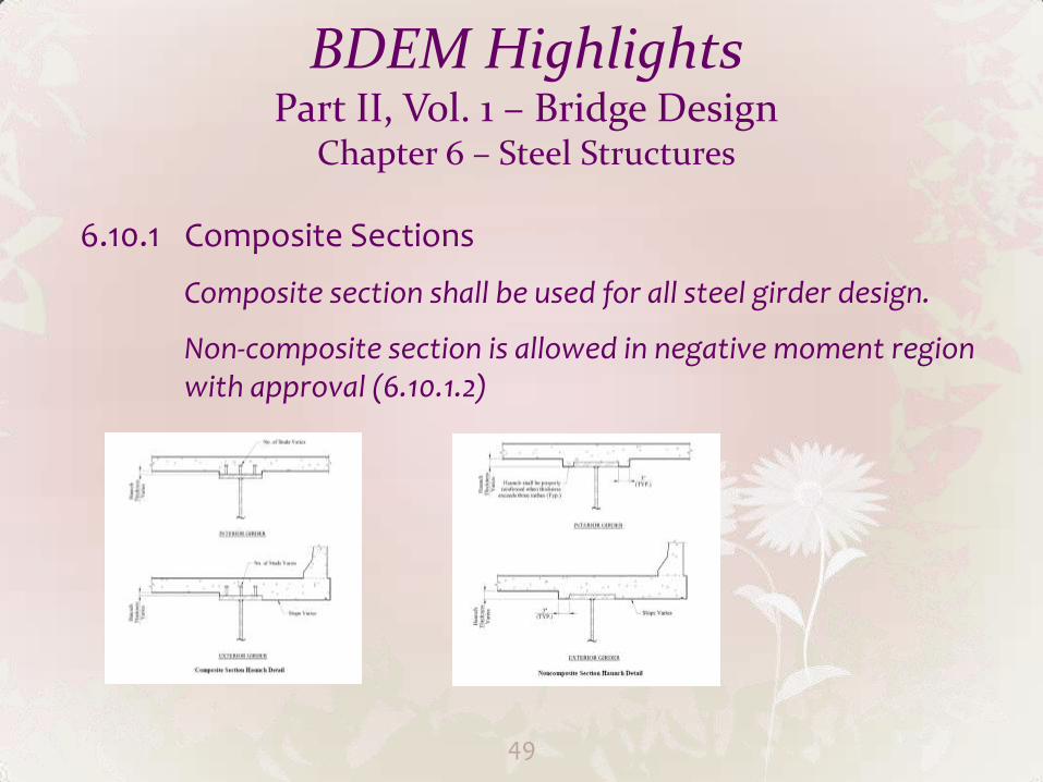
6.10.1 Composite Sections
Composite section shall be used for all steel girder design.
Non-composite section is allowed in negative moment region with approval (6.10.1.2)
49
BDEM Highlights Part II, Vol. 1 – Bridge Design
Chapter 6 – Steel Structures
6.10.10 Shear Connectors
The attachment method of shear connector to steel girders (Field weld or shop weld) should be contractor’s choice. Do not specify the method in plan.
However, designers shall ensure the attachment methods for shear connector are shown on steel girder shop drawings.
50
BDEM Highlights Part II, Vol. 1 – Bridge Design
Chapter 9 – Deck and Deck Systems
9.7 Concrete Deck Slabs
Overall Depth: 8”, 8.5”, 9”, 9.5” (including ½” sacrificial thickness)
7”, 7.5” (Movable bridge only)
Top cover: 2.5” (2” for movable bridge only)
Bottom cover: 1.5”
51
BDEM Highlights Part II, Vol. 1 – Bridge Design
Chapter 9 – Deck and Deck Systems
9.7.2 Empirical Design
Not allowed
9.7.3 Traditional Design
LADOTD Deck Design Tables (Part III, Chapter 2)
Interior regions (overhang and its adjacent region need to be designed)
7” maximum rebar spacing
Doubly reinforced concrete theory is not allowed in deck design
52
BDEM Highlights Part II, Vol. 1 – Bridge Design
Chapter 9 – Deck and Deck Systems
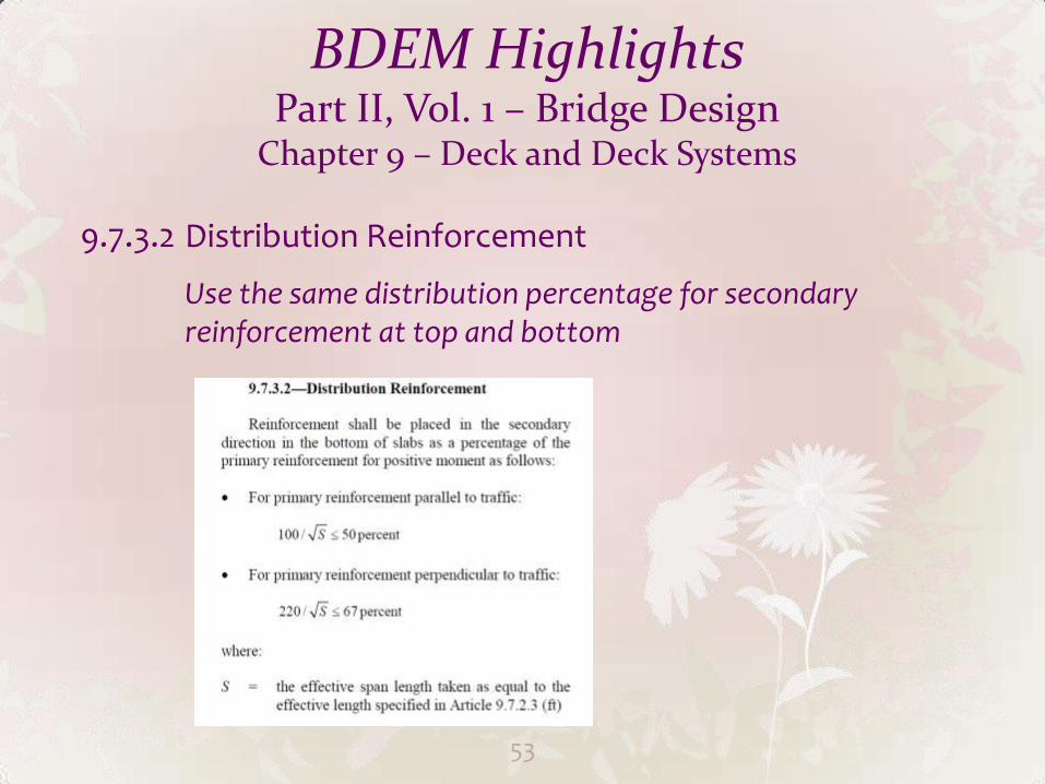
9.7.3.2 Distribution Reinforcement
Use the same distribution percentage for secondary reinforcement at top and bottom
53

Future Work Part I – Policies and Procedures (Chapter 5, 7, 8)
Incorporate all valid information in archived manuals to BDEM
Part II, Volume 1 – Work with Geotechnical Section to incorporate all foundation design provisions (Chapter 10, 11 &12)
Part II Volume 5 – Incorporate the current rating guideline
Part III Chapter 1 - LG Standards/Bearing Pad Design Charts
54
Future Work
Incorporate New Standard Specifications
Research Initiatives - Intermediate Diaphragm Study, Link Slab Study and Floating Span, Internal Curing Concrete, Integral Bridge, Wave Atlas Development for Louisiana Coastal Area
AASHTO SCOBS T-10 (Concrete Design) Technical Committee Chapter 5 Reorganization (Ballot in June 2016 in AASHTO SCOBS Annual Mtg.)
55

56