Embed Size (px)
Citation preview

Ž .Wear 225–229 1999 954–961
Laboratory simulation to select oil seal and surface treatment
Mark Shuster ), Ray Seasons, Doug BurkeDana, 8000 Yankee Road, Ottawa Lake, MI 49267, USA
Abstract
Reliability of rotary oil seals depends on many parameters related to seal design and material, shaft material, hardness and surfacetexture, medium; operating conditions, etc. This presentation will describe the accelerated testing methodology development as well as theresults of shaft surface roughness and hardness analyses to decrease wear in rotary oil seal lips. Seals went through 200 h of acceleratedtesting which not only reproduced operating conditions but duplicated field service mode or seal lip and shaft wear mechanisms during
Ž .accelerated testing. Dana’s new oil seal accelerated tester has many unique features: 1 reproduction of several extreme operatingŽ .conditions including oil temperature cycling and superposition of reciprocal motion; 2 devices to easily change shaft-to-bore
Ž .misalignment and shaft eccentricity, and 3 measurement equipment for torque evaluation and photo-optical oil leak detection. Themethodology consists of establishing simple engineering parameters including the number of tested cycles before the leak, oil seal lipwear path, shaft surface groove depth under oil lip, varieties of shaft surface roughness, and friction forces between seal lip and shaftsurface. An important part of this methodology is detailed metallurgical and metrological examination of the field and lab test usage ofthe oil seal lips and shaft surfaces including SEM and EDX analysis. The shaft surface hardness and roughness characteristics, includingcore roughness depth, reduced peak height and valley depth, their ratios, and their influence on seal lip wear will be presented. q 1999Elsevier Science S.A. All rights reserved.
Keywords: Oil seal; Surface treatment; Wear
1. Introduction
Usually cars or trucks lose their working capacity as aresult of malfunction or breakdown of a limited number ofsurfaces, parts or components. These vehicles mostly carryeither a heavy load or work under extremely stressful and
w xcomplex conditions 1 . The rotary oil seal system is one ofthese limited warranty components. This extremely usefulsystem, which at first glance seems simple, has existed fora long time. One of the distinctions of this system consistsof many important parameters influencing wear. The rea-sons for wear within this system can be parameters relatedto seal material, design, medium ambient, housing, shaftand operation. Confounding this extremely elaborate tribo-logical issue, we have one more complication: each of thethree main representatives of the rotary oil seal system isproduced by a different industry: material for oil seal, steelor iron for machine shaft surface and the oil itself. Thereexists a lot of in-depth research in each area which ana-
) Corresponding author. Fax: q 1-4195354276; e-mail:[email protected]
lyzes this system strictly from its industry perspective. Andin the case of leak or failure, representatives of the differ-ent industries complain about each other rather than im-prove their own product.
Shaft surface plays a very important role in rotary oilseal system. Detailed analysis of the oil seal shows thatmore than 30% of the total problem belongs to roughness
w xof a surface 3 . In spite of this, the existing recommenda-tion for required performance of the shaft surface wascreated 30 years ago without any subsequent revision, inspite of high level of modern achievement in the area ofmeasurement and also in the area of machining surfaces. Itis enough to say that today we have only one recom-mended parameter for shaft surface description. The samevalue for these parameters can describe completely differ-ent surfaces. So, the main problem consists not only indeveloping an accelerated testing machine, but providingspecial methodology for rotary oil seal testing depends onanalyzed parameters.
Most often, the testing continues until a leak occurs thatusually depends on numerous parameters and even in thecase of bench tests leaks appears after 3000 h of testing
0043-1648r99r$ - see front matter q 1999 Elsevier Science S.A. All rights reserved.Ž .PII: S0043-1648 99 00055-1

( )M. Shuster et al.rWear 225–229 1999 954–961 955
Fig. 1. Rotary pinion oil seal representatives after 46,000 km of fieldusage in sport utility vehicle.
w x3 . Some published results based on testing and reproduc-tion of the rotary oil seal leak after 10–40 h of testingcannot be considered reliable enough without proving the
w xduplication of the same field wear mode 4,5 . As for realservice conditions, a leak or failure is rarely repeatablebecause many parameters influence the rate of wear. Exist-ing testing methodology has not provided the number ofmeasurement parameters necessary for analysis.
Nothing is better than controlled field-testing. But suchtests are extremely expensive. Accelerated tribological test-ing of rotary oil seal system is getting more attentionbecause of the longer life of parts, the high cost of fieldtesting, environmental issues related to leak prevention,etc. Accelerated testing reproduces operating conditions ofthe field with some kind of accelerating effect so as toreceive results faster. So the main idea of acceleration is toreduce test time. To achieve this desired objective, one ormore parameters associated with friction between oil seallip and shaft surface need to be more severe in the test
w xthan is associated with field usage 1,2 .For accelerated oil seal testing, increased velocity has
often been used which causes such a temperature increasethat unreconstructible processes in surfaces and subsurfaceof this system are created which do not exist in real
Fig. 2. SEM top view of the rotary pinion seal after 46,000 km of fieldusage in sport utility vehicle.
Fig. 3. Profile and wear of the shaft surface under different seal lips after46,000 km field usage.
conditions. While testing rotary oil seal components, manyparameters influence wear rate. It is extremely complicatedto repeat sometimes unstable performance material forseal, oil and shaft surface conditions. Large scatter canresult from changes in humidity, presence of oxygen orany additives in oil, different friction modifiers, etc. Thisproblem suggests a more appropriate approach would be toreplicate not the above-described normal operating condi-tions, but to focus laboratoryrbench testing on producingthe same oil seal lip and corresponding shaft surfacedamage as that produced during field usage. During failureanalysis of the field-leaked seal, it is critical to define thedominant type of damage and the root cause of the prob-lem. We then need to create some controlled, reproducibleconditions that will lead to oil seal lip destruction by thesame mechanism. We must formulate the qualitative andquantitative parameters, which describe the complicatedphenomena between seal and shaft.
2. Field usage oil seal and shaft surface analysis
In spite of a proliferation of published papers, only afew of them contain detailed description of the wear
w xmechanism of the seal 6–8 . But in these cases, we alsosee a one-sided approach from the seal or from the oilonly. Sometimes the authors draw conclusions and make arecommendation to follow only one parameter, for in-
Fig. 4. Accelerated oil seal test machine.
( )M. Shuster et al.rWear 225–229 1999 954–961956
Fig. 5. Top view of the oil seal lip after 200 h of accelerated testing withrotating and reciprocal motions.
stance, fluorine or sulfur distribution through the oil sealw xcross-section 6 . In reality, oil seal is a tribological system
which consists of oil seal, shaft surface and oil. The typicalanalysis of the field usage parts includes the followingmajor steps.
Ž .1 Discover history of the shaft seal system.Ž .2 Determine system operating conditions, including
speed, pressure, temperature, contaminations, etc.Ž .3 Analyze shaft seal joint parameters including de-
sign, geometry, tolerances, eccentricity, misalignment, etc.Ž .4 Inspect oil seal and shaft surfaces visually. During
this stage, we have to gather oil, ‘sludge’, inside andoutside of the seal; measure profile and roughness of theshaft surfaces; check the spring condition and perfor-mance.
Ž .5 Request scanning electron microscopy and energydispersive spectroscopy to analyze shaft surface, oil,‘sludge’, other liquid contaminants and the dirt particles inthe oil and wear debris and compare phase analyses on theseal lip at different areas.
Ž .6 Produce metallurgical examination of the shaft mi-crostructure, shaft and seal microhardness distribution
Žthrough shaft cross-section in two directions transverse.and axially , using Vicker’s, Knoop’s and Walase’s tech-
niques.Ž .7 Define possible root causes of the problem and
formulate requirements for long-life shaft seal system.
Each rotary oil seal system is slightly different. Let us,for example, describe the analysis of the pinion oil sealsystem after 46,000 km usage in a sport utility vehicle.Fig. 1 shows a top view of the oil seal system componentsafter field usage. To make it easy to understand theterminology, Fig. 2 shows the location of the dust, middleand oil lips. Also, in balloons we can see EDX results ofchemistry in the different lips after 46,000 km. This analy-sis points to iron, silicon and aluminum particle presenceat the dust and middle lip as a result of abrasive contami-nation from outside. The chemistry of the oil lip is differ-ent in comparison with dust and middle lips because of asulfur content that is evidence of seal lip material deterio-ration due to friction reaction between shaft, seal and oilbetween them. The presence of the sludge of oil betweenmiddle and oil lips indicates temperature, oil friction modi-fier or other complicated processes between seal and shaftw x9 . The oil seal lip looks like a desert surface that ischaracterized by multiple separated plateaus with crackingbetween them. The profile and wear measurement data ofthe steel shaft after field usage with this oil seal lip isshown in Fig. 3. We can see the different values of theshaft surface wear under dust, middle and oil seal lips.
3. Accelerated testing methodology development
Testing of the oil seals can take place in one of twoways—they can either be tested as an assembly in theapplication it is intended or they can be tested using a sealtest machine. Existing rotary oil seal testers reproducesome of the operating conditions. Because the rotary oilseal evaluation usually belongs to the seal manufacturer,they fall short in providing a full array of extreme testconditions which simulate the actual oil seals used inautomotive applications typically experience. For, exam-ple, it is not common for an oil seal used in automotiveapplications to experience a wide variance in temperature.Also, many applications subject the oil seal to certainmisalignments such as shaft-to-bore misalignment and shaftout-of-round condition.
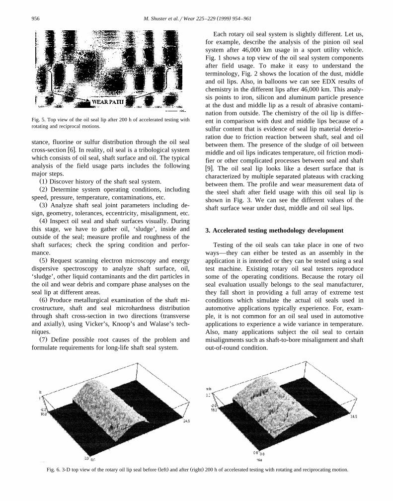
Ž . Ž .Fig. 6. 3-D top view of the rotary oil lip seal before left and after right 200 h of accelerated testing with rotating and reciprocating motion.

( )M. Shuster et al.rWear 225–229 1999 954–961 957
Fig. 7. Shaft surface and wear groove measurement results after 200 h ofaccelerated testing with rotating motion only.
Ž .A new oil seal accelerated tester Fig. 4 has manyunique features including oil temperature cycling, superpo-sition of reciprocal motion, torque measurement, devicesto easily change shaft-to-bore misalignment and shaft ec-centricity, and photo-optical oil leak detection. In order toprovide the temperature cycling, oil seal tester includesmeans for heating and cooling the source of oil. Reactiontorque measurement apparatus is depicted as a strain gaugeload cell having one end connected to seal mountinghousing and opposite end anchored to reference shaftsurface. The reaction torque signal is presented to PLCController on display terminal. Shaft-to-bore misalignmentapparatus is comprised of treated device and can be ef-fected without stopping or otherwise disturbing an ongoingseal test. Shaft run-out can generally be defined by themisalignment between the geometrical center of a shaftand its axis of rotation. Fluid detection apparatus is com-prised of a graduated cylinder which is calibrated involumetric units and can be used to collect the oil whichescapes past the sealing surface and allows for a directmeasure of its volume. A photo detector fastened belowseal provides information about each time a drop of oilfalls from the seal. The detailed description of these appa-
w xratuses are published in Ref. 10 .
Acceleration of the rotary oil seal lip wear was achievedby increasing rotation speed up to 5000 rpm and a combi-
Ž .nation of the eccentricity 0.010 min. , shaft-to-bore mis-Ž .alignment 0.010 min. with reciprocal motion and 2258F
oil temperature.The electron scanning microscope with EDX analysis of
the dust, middle and oil seal lips after accelerated testingshow that the process of the oil seal degradation happenedonly at both oil seal lips after field usage and acceleratedtesting of the parts. As for the dust and middle seal lips,the SEM and EDX analyses proved absence of any changesat seal working surfaces, in spite of superposition of theacceleration factors.
The oil lip surface after 200 h of accelerated testingŽ .Fig. 5 is characterized by multiple cracking located per-pendicular to lip running. EDX analysis shows decreasesof the fluorine percentage and simultaneously the Sulfur
Žpresence as an evidence of seal lip material Viton in our.case degradation. The comparison of the oil seal lip EDX
analysis after 200 h of accelerated testing and field failurefingerprints points to the same lip wear mechanism.
Fig. 6 shows the new and tested oil seal lip after 200 hwith reciprocal and rotation motion. The 3-D image showstypical oil seal lip cracking as a result of lost elasticity.Evidence of this phenomenon can be seen in results ofEDX analysis of the top view and cross-section of the oilseal lip. The degradation of the seal lip occurred only inthe thin layer. The middle part of the seal lip has the samestructure and composition as a new seal before testing.
The main problem of rotary oil seal accelerated testingand evaluation consists not only in developing an acceler-ated testing machine, but providing special methodologyfor testing. The measurement methodology consists ofestablishing the simple engineering parameters that canhelp to evaluate and select a better oil seal design andmaterial, shaft machining processes andror roughness pa-rameters, different oil or special additives, etc. The sub-stantial changes of the shaft surface roughness and round-ness; shaft surface and oil seal lip wear path and seal oillip mechanism; and also friction forces between oil seal
Table 1Typical data-test results from oil seal lip and shaft surfaces measurement after 200 hours of accelerated testing
M-machining series vs. current technology
Ž . Ž . Ž . Ž .Part a Friction lbs. Ra under oil lip mM Oil lip wear path Shaft groove Oil seal leakage hŽ . Ž .mM mMBefore After Before Break-in Hours
5 0.075 0.260 374.90 215.72 200 240–260 1.575 no leak6 0.075 0.260 369.32 257.81 200 240–255 2.565 no leak7 0.200 0.385 258.06 192.79 200 290–310 1.422 no leak9 0.200 0.385 361.19 250.19 140 265–285 3.149 no leak
10 0.135 0.275 291.08 270.51 100 310–325 1.143 no leakCurrent tech. 1.243 0.608 136.09 132.59 95 283 3.505 no leak
‘Ra’ measurements taken using a 0.060 in. assessment length.

( )M. Shuster et al.rWear 225–229 1999 954–961958
Fig. 8. Wear of the oil seal lip tested 200 h in contact with differentsurface machining.
and the shaft are measurement indicators for sealing sys-tem evaluation. Part of any methodology is detailed metal-lurgical and metrological examination of the field usage oilseal lip and shaft surface including SEM and EDX analy-sis. As for a metrological technique, we need to analyzethe substantial changes of the shaft surface roughness androundness. Seventeen different parameters of roughness,including Ra, Rz, RzDIN, Rmax, R3zm, Rq, Sk, Rp, Pc,Sm, Wt, Rk, Rpk, RpkU , Rvk, RvkU and A2 or Vo areused for shaft surface analysis after every 20 h of testing.
With reciprocal and rotating motions, a new oil sealaccelerated tester and methodology provide oil seal leak-age after less than 100 h of testing due to reproduction ofthe same seal lip wear as after field usage. The hard shaftsurface roughness exhibited very little change during thistest. Without reciprocal motion, the hard shaft surfaceŽ .HRc 65 had substantial damage under the oil lip after
Ž .more than 100 h of accelerated testing Fig. 7 . The SEMand EDX analysis showed the same wear mechanism asafter the field usage testing—degradation happened only atthe surface layer but not in any unworn area or in the
w xmiddle part of the seal lip 2 .
4. Shaft surface machining selection for seal life im-provement
Depending on the problem or the testing goal, testingequipment and methodology can be adjusted to each indi-vidual test. In order to analyze the shaft surface influenceon rotary seal life improvement, the Dana acceleratedtester was used without reciprocal motion. The 36-mm-di-ameter rotary seal from Viton was tested with eccentricityŽ . Ž .0.010 min. and shaft-to-bore misalignment 0.010 min. .This test was performed for 200 h at 5000 rpm and 2258Fagainst different shaft machining surfaces.
Table 1 shows the typical data-measurement results ofthe tested surfaces. These parameters include:1. Number of hours or cycles before leak2. Number of hours or cycles before break-in3. Maximum oil seal lips wear path4. Maximum shaft surface wear under lip5. Shaft surface roughness changes6. Friction between seal and shaft surfaces
In addition, any details of the oil seal lips and shaftsurface friction and wear mechanism, such as apparent lipcracking or changes in sulfur and fluorine percentage, canbe valuable parameters to help select the best shaft surfacemachining process for seal life improvement. Surfaceroughness parameters are important for the definition ofthe wear mechanism. In addition to the well-known RaŽ .roughness average profile measurement, we can use otherparameters. Rz—the mean third highest peak-to-valleyheight, this roughness parameter disregards the few highpeaks and valleys in a surface that usually have little effecton the performance of the part. Tp—Bearing ratio, param-eter is probably the most elegant description of a surfaceand is applicable to practically any application where twoprecision surfaces are interacting. Rk—core roughnessdepth, parameter has enormous practical significance. LowRk represents a surface with long-life characteristics. Rvk,
Ž . Ž .Fig. 9. 3-D top view of the soft top and hard bottom shaft surfaces after 200 h accelerated testing.
( )M. Shuster et al.rWear 225–229 1999 954–961 959
RvkU and Rpk, RpkU—reduced and maximum valley depthand peak height correspondingly are representatives of theRk family parameters. Table 1 shows that this methodol-ogy provides engineer-proven data for this selection. Fig. 8demonstrates that oil seal lip wear depends on differentshaft surface machining processes. The wear of the seal lipequals 100% after 200 h of accelerated testing in contact
Žwith shaft ground by current machining processes Ra.5–10 min., HRc 60–64 . The most popular alternative
machining processes based on industry recommended pa-Ž .rameters Ra 10–20 min., HRc 45 min show more oil seal
lip wear in comparison with current shaft machining. Inother words, current Dana axle shaft machining processessecure good oil seal life. However, use of a relatively soft
Žshaft surface with a special cross-hatched structure subse-
.quently referred to as ‘D-machining process’ providessignificantly lower oil seal wear. Shaft wear underneaththe oil seal lip as measured both by contact stylus type of
Ž .equipment Hommel and noncontact optical measurementŽ . Ž .Wyko shows that the soft HRc 20 shaft with a specialtextured surface has also lower wear value than the hardŽ .HRc 60 shaft produced by traditional machining pro-
Ž .cesses see Fig. 9 .Extremely important in the investigation were the re-
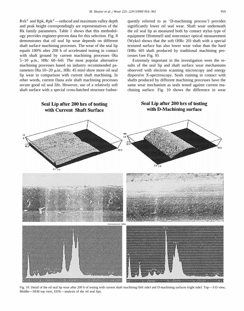
sults of the seal lip and shaft surface wear mechanismsobserved with electron scanning microscopy and energydispersive X-spectroscopy. Seals running in contact withshafts produced by different machining processes have thesame wear mechanism as seals tested against current ma-chining surface. Fig. 10 shows the difference in wear
Ž . Ž .Fig. 10. Detail of the oil seal lip wear after 200 h of testing with current shaft machining left side and D-machining surfaces right side . Top—3-D view,Middle—SEM top view, EDX—analysis of the oil seal lips.

( )M. Shuster et al.rWear 225–229 1999 954–961960
Ž .Fig. 11. Correlation of the oil seal lip wear and RvkyRpk rRvk parameters of the shaft surfaces after 200 h of accelerated testing.
Ž .mechanism between traditional processes left side and ashaft with special structure. As we can see, this cross-hatched texture of shaft surface provides not only signifi-
Ž .cantly less lip wear see Fig. 8 but different degradationmechanism on oil seal lips. A bigger percentage of fluorineŽ . Žas an evidence of elasticity and absence of sulfur related
.to seal lip degradation mechanism indicate enhanced fric-Žtion between oil seal lip and the soft shaft surface right
.side . The positive influence of these processes can createthe same effect as the changes provided by the use ofbetter heat and wear resistant seal lip materials. It is hardto recognize the independent influences of the specialcross-hatched texture and relatively soft hardness of thisshaft.
A well-known recommendation exists for a minimumw x45 HRc hardness for rotary oil seal shaft surface 11 .
When the shaft has a single surface for sealing and bearingfunctions, such recommendation makes sense. Also, suchhardness can partially decrease damage from abrasive par-ticles between oil seal lip and shaft surface partially be-cause much tribological research related to abrasive wearproves that significant prevention of this type of wearoccurs when surface hardness is more than 1.7 time greater
w xthan the hardness of the abrasive particles 12 . HardnessŽof the most common dust particles SiO , Al O , FeO,2 2 3
.etc. is often greater than 1000 Hv, and it is difficult toprovide such hardness for the regular shaft surface of caror truck axle applications. It is much smarter to preventabrasive wear for rotary oil seal applications.
Another purpose of this project is to identify one orseveral shaft surface roughness parameters that have themost influence on seal lip wear. Those proposed in the
w xliterature 4 did not show high correlation with seal lipwear or explain the difference between ‘good’ and ‘bad’surfaces. Our research shows that for similar machining
Ž .processes, the ratio RvkyRpk rRvk has some correla-Ž .tion see Fig. 11 .
5. Conclusions
Ž .1 The Dana rotary oil seal test machine and corre-sponding methodology after 200 h of accelerated testingreproduce the same type of seal lip and shaft surface wearas vehicle tested parts.
Ž .2 With reciprocating and rotating motion, the systemexhibited oil seal leakage after 60 h of testing most likelydue to seal lip wear from loss of seal elasticity.
Ž .3 Without reciprocating motion, the hard shaft surfacehad substantial damage under the oil lip after more than100 h of testing.
Ž .4 The testing methodology and measurement parame-ters provide opportunities for optimum selection of theshaft surface machining to seal life improvement.
Ž .5 Use of the soft shaft with a special cross-hatchedstructure surface results in less seal lip wear and shaftgroove damage in comparison with current oil seal ma-chining grinding surfaces processes.
( )M. Shuster et al.rWear 225–229 1999 954–961 961
References
w x1 M. Shuster et al., Accelerated Tribological Testing of AutomotiveComponents, 98NM033, 31 ISATA Congress, Dusseldorf, June 2–5,1998.
w x2 M. Shuster et al., Field Failure Mode Reproduction during Oil SealAccelerated Testing, Austrib-98, Brisbane, 1998.
w x3 Y. Masuda et al., A Simulation Test Method for Deterioration ofFKM Compounds Engine Crankshaft Oil Seals, SAE Paper No.922373, 1992.
w x4 J. Qu, Non-Ra Roughness Parameters of Shaft Surfaces for RadialLip Seal Applications, Vol. 1104, 1995 Earthmoving Industry Con-ference, Peoria, IL, 1995.
w x5 D. Jonston, Rotary Shaft Seal Friction, The Influence of Design,Material, Oil and Shaft Surface, SAE Paper No. 950764.
w x6 S. Nagasawa et al., Simulation Test Method for Deterioration ofEngine Crankshaft Oil Seals, SAE Paper a 902123.
w x7 H. Hirabayashi et al., An influence of Reciprocating Motion ofRotary Shaft on Sealing Characteristics of Oil Seals for AutomotiveTransmission, SAE Paper No. 820144, 1982.
w x8 B. Dinzburg, Rubber Elasticity—The Main Characteristic for Dy-namic Shaft Seals. Presentation at 148th Meeting of the RubberDivision, American Chemical Society, Cleveland, OH, October 17–20, 1995.
w x9 Y. Hiroshi et al., Influence of Sludge on Seal Performance, SAEPaper a 980849.
w x10 J. Antonini, M. Shuster, D. Sverdlik, Oil Seal Tester, Patent No.5,814,717 from 9r28r98.
w x11 Elastomeric Lip Seal, Handbook, CR Industries, Elgin, IL, August,1992.
w x12 Friction, Wear and Lubrication, Handbook, Vol. 1, Moscow, 1978.