Embed Size (px)
Citation preview

Dynamic Simulation System
Full Lineup Catalogue
http://www.imv-tec.com*The specifications and design are subject to change without notice.
IMV EUROPE LIMITED
1 Dunsbridge Business Park, Shepreth, Royston, Herts, SG8 6RA, United Kingdomtel.+44 1763 269978
IMV EUROPE LIMITED
Landsberger Str. 406, D-81241 München, Germanytel.+49 89 21545 9901
March. 2016Cat No.1603 ① 003DSS_CE

INDEX
Wide range of industries benefit through
quality and reliability improvements
Since it was founded in 1957, IMV has been proud to be at the forefront of
research and development in vibration testing systems, supplying
technically-advanced systems, with safety and reliability as first priorities.
The range of IMV vibration test systems includes single-axis and simultaneous
muti-axis systems for up to six degrees of freedom simulation. A range of
vibration and diagnostic instruments are also available. Engineering consultancy
services to assist customers with vibration measurement, analysis and testing
can also be provided.
IMV designs, manufactures, markets and maintains vibration-test systems
which simulate actual vibration environments, and measuring systems which
record and analyse vibration created or experienced by a product. IMV can
also provide test laboratory and consultancy services.
We are proud to be contributing to the safety and reliability of a wide range of
products by working with the automotive, aerospace, electrical machinery and
structural engineering industries to solve problems caused by vibration.
Our policy is to continue to develop our skills and products to ensure we
continue to provide the best possible service to our clients.
World’s leading supplier of high
reliability vibration test systems
Series Arrangements
[Basic Systems] Vibration Test Systems
Ecology
High Grade Range A-series
Standard Range i-series
Large Displacement Range J-series
High Excitation Force Water Cooled Range K-series
Low Acoustic Noise and Compact Range m-series
Optional Units
[Multi-axis systems] Vibration Test Systems
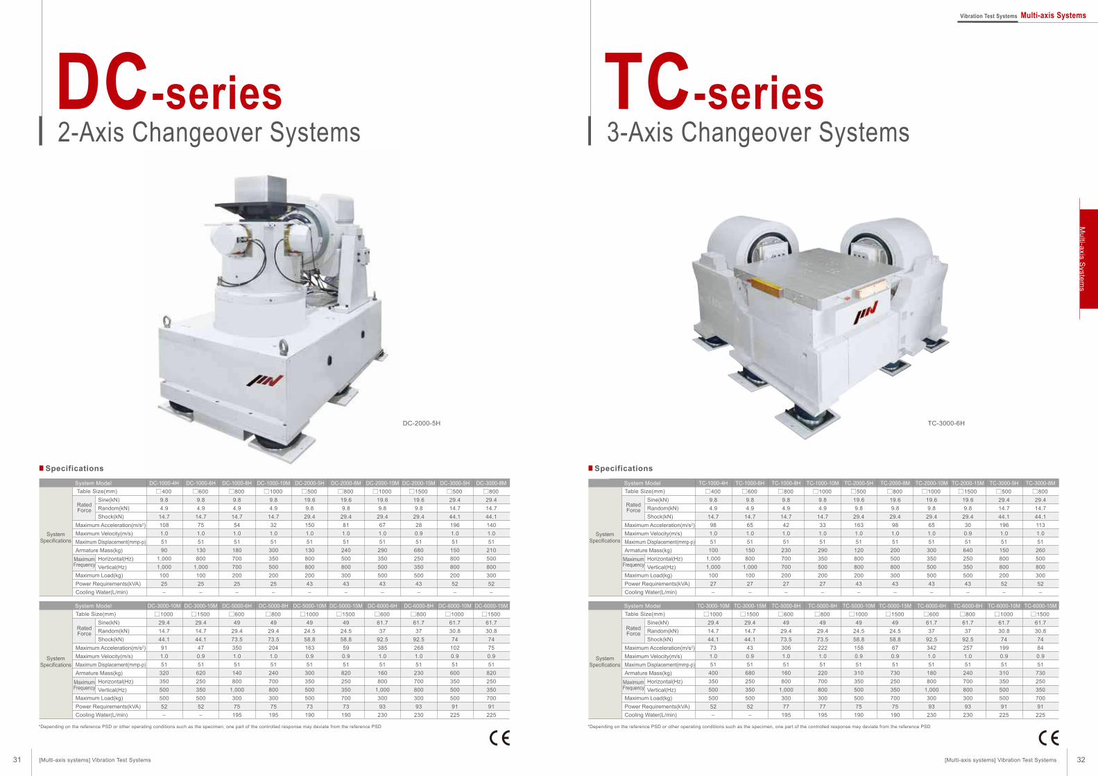
2-Axis Changeover Systems DC-series
3-Axis Changeover Systems TC-series
2-Axis Simultaneous Systems DS-series
3-Axis Simultaneous Systems TS-series
6 Degrees of Freedom Systems TTS-series
[Vibration Controller] K2
Vibration Controller K2
[Case Studies]
Automotive Parts
Electronic Parts
Transportation Test
Construction Machinery
Earthquake Resistance
Aerospace
Other Applications
System Layout
[Environmental Test Systems] Vibration Test System
Chamber for Vertical Excitation
Chamber for both Vertical and Horizontal Excitation
Chamber for Multi-Axis Excitation
Prefabricated Chamber for Large Specimens
Technical Guidance
IMV Test Lab Network
Coverage
Quality & Ecology
Conversion Table
Specifications
Excitation Force
P.03
P.07
P.09
P.13
P.15
P.17
P.19
P.21
P.31
P.32
P.33
P.34
P.35
P.37
P.44
P.48
P.49
P.50
P.51
P.52
P.53
P.54
P.56
P.57
P.59
P.60
P.61
P.65
P.67
P.69
P.70
P.71
P.73
01 02
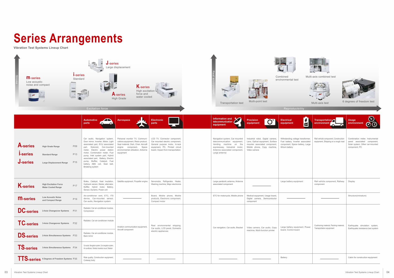
Reproducibility
Re
al e
nv
iron
me
nt
Information and
telecommunication
equipment
Precision
equipment
Automotive
parts
Standard Range
Large Displacement Range
High Excitation Force
Water Cooled Range
Low Acoustic Noise
and Compact Range
2-Axis Changeover Systems
2-Axis Simultaneous Systems
3-Axis Simultaneous Systems
6 Degrees of Freedom Systems
3-Axis Changeover Systems
Aerospace Electronic
parts
Electrical
equipment
Transportation
environment
Usage
environment
Series ArrangementsVibration Test Systems Lineup Chart
Car audio, Navigation system,
Door mirror, Inverter, Motor, Light
associated part, ECU associated
part, Solenoid, Car-mounted
meter, Electric power station
motor, Combination meter, Fuel
pump, Inlet system part, Hybrid
associated part, Battery, Electric
pump, Muffler, Catalyst, Fuel
battery, ABS coil, Seat belt,
Breaking system
Personal monitor TV, Communi-
cations equipment, Resin product,
Seal material, Dish, Chair, Aircraft
engine component, Space
environmental utilization, Airborne
equipment
LCD TV, Connector component,
Car mounted electric component,
General purpose motor, In-rack
equipment, PC, Printed circuit
board, Impact from transportation
Navigation system, Car mounted
telecommunication equipment,
Vending machine on the
expressway, Industrial motor,
Antenna associated component,
Large antenna
Industrial robot, Digital camera,
Lens, Optical equipment, Surface
mounter associated component,
Mobile phone, Copy machine,
Video camera
Withstanding voltage transformer,
Fuel battery, Inverter associated
component, Space battery, Large
lithium battery
Rail vehicle component, Construction
equipment, Shipping on a rough road
Combination meter, Instrumental
panel associated component,
Solar system, Other car-mounted
component, PC
Aviation communication equipment,
Aircraft component
Brake, Catalyst, Heat insulation,
Hydraulic sensor, Starter, alternator,
Muffler, Hybrid motor, Battery,
Sensor, Dynamo, Power unit
Satellite equipment, Propeller engine Servomotor, Refrigerator, Heater,
Washing machine, Major electronics
Large parabolic antenna, Antenna
associated component
Large battery equipment Rail vehicle component, Railway
component
Display
Air-conditioner vent, ETC, ITS
device, Car-mounted sensor,
Car audio, Navigation system
Board, Mobile phone, Mobile
products, Electronic component,
Compact motor
ETC for motorcycle, Mobile phone Medical equipment, Usage board,
Digital camera, Semiconductor
component
Structure(miniature)
Radiator, Car air-conditioner module,
Compressor
Radiator, Car air-conditioner module
Radiator, Car air-conditioner module,
Back mirror
Car audio, Navigation system, Car navigation system,
Air-conditioner, Vibration insulation mount, Radiator
Ride quality, Construction equipment,
Cutaway body
Real environmental shipping,
Car audio, LCD panel, Domestic
electric appliances
Car navigation, Car audio, Bracket Video camera, Car audio, Copy
machine, Multi-function printer
Earthquake simulation system,
Earthquake resistance test system
Cabin for construction equipmentBattery
Cushioning material, Packing material,
Transportation equipmentLarge battery equipment, Power
board, Control board
P17
P19
P31
P32
P13
P15
Transportation testMulti-point test
Combined environmental test
Multi-axis combined test
6 degrees of freedom testMulti-axis test
i-series
High Grade Range P09A-series
J-series
K-series
m-series
DC-series
TC-series
P33
P34
P35
DS-series
TS-series
TTS-series
Excitation force
Stro
ke
A-seriesHigh Grade
i-seriesStandardm-series
Low acoustic noise and compact
J-seriesLarge displacement
K-seriesHigh excitation force and water cooled
03 04Vibration Test Systems Lineup Chart Vibration Test Systems Lineup Chart
High Grade Range A-series P.09
Standard Range i-series P.13
Large Displacement Range J-series P.15
High Excitation Force Water Cooled Range K-series P.17
Low Acoustic Noise and Compact Range m-series P.19
Optional Units P.21
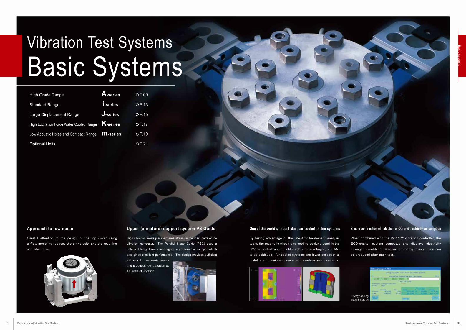
Vibration Test Systems
Basic Systems
High vibration levels place extreme stress on the main parts of the
vibration generator. The Parallel Slope Guide (PSG) uses a
patented design to achieve a highly durable armature support which
also gives excellent performance. The design provides sufficient
stiffness to cross-axis forces
and produces low distortion at
all levels of vibration.
By taking advantage of the latest finite-element analysis
tools, the magnetic circuit and cooling designs used in the
IMV air-cooled range enable higher force ratings (to 65 kN)
to be achieved. Air-cooled systems are lower cost both to
install and to maintain compared to water-cooled systems.
Careful attention to the design of the top cover using
airflow modeling reduces the air velocity and the resulting
acoustic noise.
One of the world’s largest class air-cooled shaker systems
When combined with the IMV 'K2' vibration controller, the
ECO-shaker system computes and displays electricity
savings in real-time. A report of energy consumption can
be produced after each test.
Simple confirmation of reduction of CO2 and electricity consumptionUpper (armature) support system PS GuideApproach to low noise
Energy-savingresults screen
[Basic systems] Vibration Test Systems [Basic systems] Vibration Test Systems
Ba
sic system
s
05 06
Optimised for test level
Drive signal
Optimised for test level
Speed of rotation
Control for maximum efficiency
Ecology Environmentally-friendly vibration systems
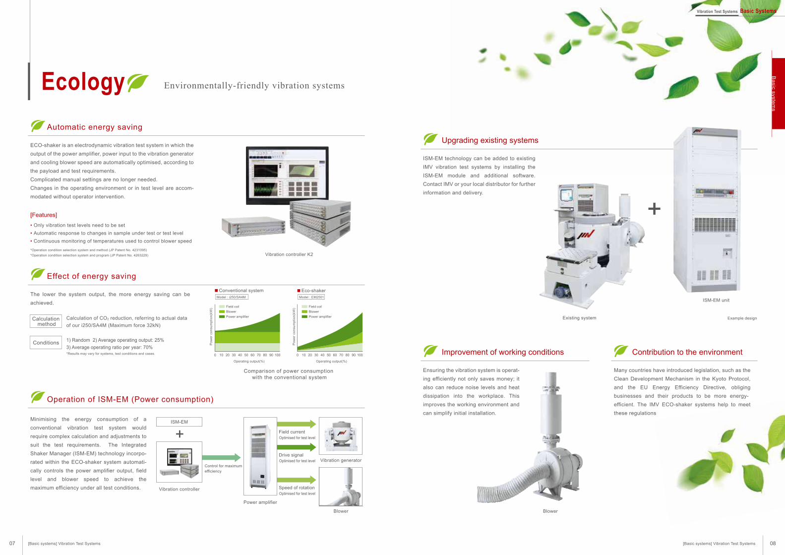
Automatic energy saving
ECO-shaker is an electrodynamic vibration test system in which the
output of the power amplifier, power input to the vibration generator
and cooling blower speed are automatically optimised, according to
the payload and test requirements.
Complicated manual settings are no longer needed.
Changes in the operating environment or in test level are accom-
modated without operator intervention.
Minimising the energy consumption of a
conventional vibration test system would
require complex calculation and adjustments to
suit the test requirements. The Integrated
Shaker Manager (ISM-EM) technology incorpo-
rated within the ECO-shaker system automati-
cally controls the power amplifier output, field
level and blower speed to achieve the
maximum efficiency under all test conditions.
Upgrading existing systems
ISM-EM technology can be added to existing
IMV vibration test systems by installing the
ISM-EM module and additional software.
Contact IMV or your local distributor for further
information and delivery.
Improvement of working conditions
Ensuring the vibration system is operat-
ing efficiently not only saves money; it
also can reduce noise levels and heat
dissipation into the workplace. This
improves the working environment and
can simplify initial installation.
Many countries have introduced legislation, such as the
Clean Development Mechanism in the Kyoto Protocol,
and the EU Energy Efficiency Directive, obliging
businesses and their products to be more energy-
efficient. The IMV ECO-shaker systems help to meet
these regulations
Effect of energy saving
The lower the system output, the more energy saving can be
achieved.
Operation of ISM-EM (Power consumption)
[Features]
• Only vibration test levels need to be set
• Automatic response to changes in sample under test or test level
• Continuous monitoring of temperatures used to control blower speed
*Operation condition selection system and method (JP Patent No. 4231095)
*Operation condition selection system and program (JP Patent No. 4263229)
*Results may vary for systems, test conditions and cases.
Calculation method
Calculation of CO2 reduction, referring to actual data
of our i250/SA4M (Maximum force 32kN)
Comparison of power consumption with the conventional system
Conditions 1) Random 2) Average operating output: 25%
3) Average operating ratio per year: 70%
Po
we
r co
nsu
mp
tio
n(k
W)
Po
we
r co
nsu
mp
tio
n(k
W)
Model : i250/SA4M Model : EM2501
Operating output(%)
Field coil
Blower
Power amplifier
Field coil
Blower
Power amplifier
100 20 30 40 50 60 70 80 90 100
Operating output(%)
100 20 30 40 50 60 70 80 90 100
Conventional system Eco-shaker
ISM-EM
Vibration controller
Vibration controller K2
Power amplifier
Vibration generator
Blower
Optimised for test level
Field current
Blower
Existing system
ISM-EM unit
Example design
Contribution to the environment
[Basic systems] Vibration Test Systems [Basic systems] Vibration Test Systems
Vibration Test Systems Basic SystemsB
asic syste
ms
07 08
A new standard created by listening to our customers.
A wider range of test requirements and higher test specifications.
A-series meets the needs for such a versatile test environment.
Advanced automatic energy saving, high level of functionality and a protected test environment.
A-series improves the working environment of vibration testing.
[Improvement of performance]
[User friendly and Secure]
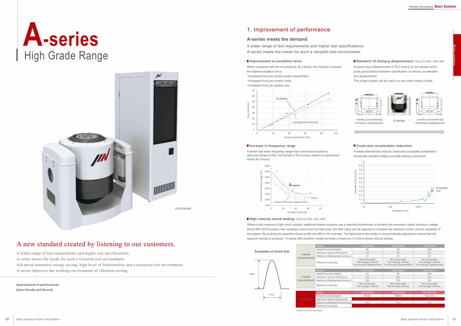
A-seriesHigh Grade Range
A-series meets the demand
A wider range of test requirements and higher test specifications.
A-series meets the needs for such a versatile test environment.
When compared with the conventional i & J-series, the A-series increases
the relative excitation force.
・Increased force per system power requirement
・Increased force per system mass
・Increased force per system size
A-series has a displacement of 76.2 mmp-p (3 inch stroke) which
gives good balance between specification of velocity, acceleration
and displacement.
This single system can be used in a very wide variety of tests.
A-series has wider frequency range than conventional systems.(Secured stroke of A30, A45 & A65 is 76.2 mmp-p based on mechanical stroke 82 mmp-p)
Where a test requires a high shock velocity, traditional shaker systems use a matching transformer to achieve the necessary higher armature voltage.
Since IMV’s ECO-system has complete control over the field level, the field value can be adjusted to increase the maximum shock velocity capability of
the system. By entering the specified shock profile into IMV’s K2 controller. The field level in the shaker is aoutomatically adjusted to ensure that the
required velocity is achieved. A-series (EM amplifier model) provides a maximum of 4.6m/s shock velocity testing.
A-series dramatically reduces cross-axis (crosstalk) acceleration
(horizontal vibration).Highly accurate testing is achieved.
Examples of shock test
100G
11ms
i-series(conventional)
Model
Rated Force Shock(kN)
Maximum Velocity Shock(m/s)Maximum Displacement (mmp-p)
Maximum Load (kg)
i240/SA3M
48
2.2
51
Not achievable*not enough velocity
*not enough displacement
i250/SA5M
80
2.2
51
Not achievable*not enough velocity
*not enough displacement
i260/SA7M
108
2.2
51
Not achievable*not enough velocity
*not enough displacement
J-series(conventional)
Model
Rated Force Shock(kN)
Maximum Velocity Shock(m/s)Maximum Displacement (mmp-p)
Maximum Load (kg)
J240/SA4M
55
2.4
100
Not achievable*not enough velocity
J250/SA6M
80
2.4
100
Not achievable*not enough velocity
J260/SA7M
108
2.4
100
Not achievable*not enough velocity
A-series
Model
Rated Force Shock(kN)
Maximum Velocity Shock(m/s)Maximum Displacement (mmp-p)
Maximum Load (kg)
*Maximum load on bare table
A30/EM3HM
60(50)
2.5(3.5)
76.2
18
A45/EM5HM
90(80)
2.5(3.5)
76.2
31
A65/EM7HM
130(120)
2.5(3.5)
76.2
50
10
1
0.9
0.8
0.7
0.6
0.5
0.4
0.3
0.2
0.1
0
1000100
Frequency (Hz)
Cro
ssta
lk (
(m/s
2)/
(m/s
2))
A65A-series
i-series(conventional)
0 20 40 60 80 100
70
60
50
40
30
20
10
0
Power requirement (kVA)
Sin
e f
orc
e (
kN)
A-series
A-series J-series (conventional)100mmp-p displacement
i-series (conventional)51mmp-p displacement
1. Improvement of performance
A30/EM3HM
Increase in frequency range Cross-axis acceleration reduction
Standard 76.2mmp-p displacement *Only for A30, A45, A65Improvement in excitation force
High velocity shock testing *Only for A30, A45, A65
[Basic Systems] Vibration Test Systems [Basic Systems] Vibration Test Systems
Ba
sic system
s
09 10
Vibration Test Systems Basic Systems
0 20 40 60 80
5000
4500
4000
3500
3000
2500
2000
1500
Excitation force (kN)
Maxi
mum
fre
quency
range (
Hz)
i-series
J-series(100mmp-p displacement)
A-series
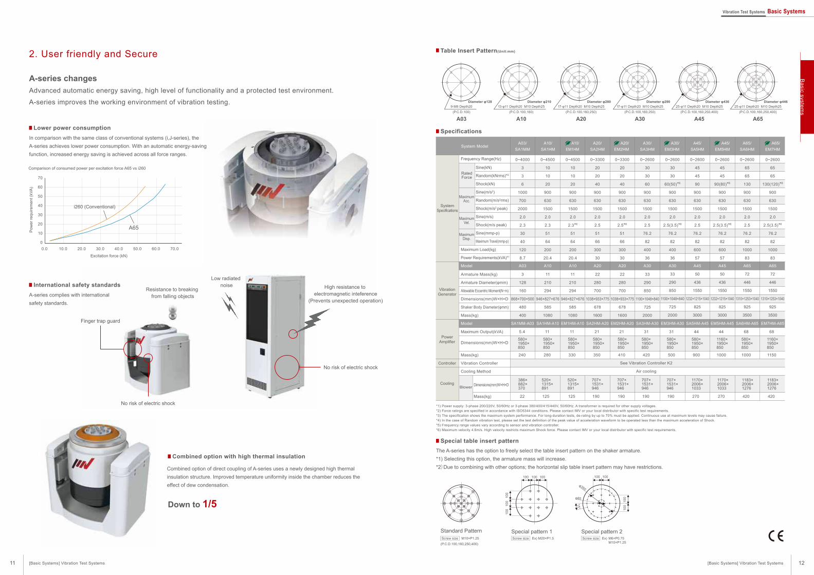
Table Insert Pattern(Unit:mm)
Specifications
*1) Power supply: 3-phase 200/220V, 50/60Hz or 3-phase 380/400/415/440V, 50/60Hz. A transformer is required for other supply voltages.
*2) Force ratings are specified in accordance with ISO5344 conditions. Please contact IMV or your local distributor with specific test requirements.
*3) The specification shows the maximum system performance. For long-duration tests, de-rating by up to 70% must be applied. Continuous use at maximum levels may cause failure.
*4) In the case of Random vibration test, please set the test definition of the peak value of acceleration waveform to be operated less than the maximum acceleration of Shock.
*5) Frequency range values vary according to sensor and vibration controller.
*6) Maximum velocity 4.6m/s. High velocity restricts maximum Shock force. Please contact IMV or your local distributor with specific test requirements.
System Model
Model
Frequency Range(Hz) 0~2600
65
65
130(120)*6
900
630
1500
2.0
2.5(3.5)*6
76.2
82
1000
83
EM7HM-A65
Maximum Load(kg)
Power Requirements(kVA)*1
Armature Mass(kg)
Armature Diameter(φmm)
Allowable Eccentric Moment(N・m)
Dimensions(mm)W×H×D
Shaker Body Diameter(φmm)
Mass(kg)
Maximum Output(kVA)
Dimensions(mm)W×H×D
Mass(kg)
Vibration Controller
Cooling Method
Dimensions(mm)W×H×D
Mass(kg)
Sine(kN)
Random(kNrms)*2
Shock(kN)
Sine(m/s2)
Random(m/s2rms)
Shock(m/s2 peak)
Sine(m/s)
Shock(m/s peak)
Sine(mmp-p)
Maximum Travel(mmp-p)
72
446
1550
1310×1253×1040
925
3500
68
1160×1950×850
1150
1183×2006×1276
420
0~2600
65
65
130
900
630
1500
2.0
2.5
76.2
82
1000
83
A65/
SA6HM
SA6HM-A65
72
446
1550
1310×1253×1040
925
3500
68
580×1950×850
1000
1183×2006×1276
420
0~2600
45
45
90(80)*6
900
630
1500
2.0
2.5(3.5)*6
76.2
82
600
57
A45/
EM5HM
EM5HM-A45
50
436
1550
1232×1215×1040
825
3000
44
1160×1950×850
1000
1170×2006×1033
270
0~2600
45
45
90
900
630
1500
2.0
2.5
76.2
82
600
57
A45/
SA5HM
SA5HM-A45
50
436
1550
1232×1215×1040
825
3000
44
580×1950×850
900
1170×2006×1033
270
0~2600
30
30
60(50)*6
900
630
1500
2.0
2.5(3.5)*6
76.2
82
400
36
A30/
EM3HM
EM3HM-A30
33
290
850
1100×1048×840
725
2000
31
580×1950×850
500
707×1531×946
190
0~2600
30
30
60
900
630
1500
2.0
2.5
76.2
82
400
36
A30/
SA3HM
A03/
SA1MM
A20/
SA2HM
SA3HM-A30SA1MM-A03 SA2HM-A20 EM2HM-A20
Model A65A65A45A45A30A30
33
290
850
1100×1048×840
725
2000
0~3300
20
20
40
900
630
1500
2.0
2.5*6
51
66
300
30
A20
22
280
700
1038×933×775
678
1600
0~3300
20
20
40
900
630
1500
2.0
2.5
51
66
300
30
A20
22
280
700
1038×933×775
678
1600
0~4500
10
10
20
900
630
1500
2.0
2.3
51
64
200
20.4
A10
11
210
294
946×827×676
585
1080
0~4500
10
10
20
900
630
1500
2.0
2.3*6
51
64
200
20.4
A10
11
210
294
946×827×676
585
1080
0~4000
3
3
6
1000
700
2000
2.0
2.3
30
40
120
8.7
A03
3
128
160
868×700×500
480
400
31
580×1950×850
420
5.4
580×1950×850
240
21
580×1950×850
410
21
580×1950×850
350
11
580×1950×850
330
11
580×1950×850
280
707×1531×946
190
520×1315×891
125
707×1531×946
190
707×1531×946
190
520×1315×891
125
386×882×370
22
Special table insert pattern
A-series changes
Advanced automatic energy saving, high level of functionality and a protected test environment.
A-series improves the working environment of vibration testing.
In comparison with the same class of conventional systems (i,J-series), the
A-series achieves lower power consumption. With an automatic energy-saving
function, increased energy saving is achieved across all force ranges.
0.0 10.0 20.0 30.0 50.0 60.0 70.040.0
70
60
50
40
30
20
10
0
Excitation force (kN)
Comparison of consumed power per excitation force A65 vs i260
Pow
er
requirem
ent
(kV
A)
A65
i260 (Conventional)
A30 A45 A65
Diameter φ29017-φ11 Depth20 M10 Depth25
(P.C.D.100,160,250)
Diameter φ43625-φ11 Depth20 M10 Depth25
(P.C.D.100,160,250,400)
Diameter φ44625-φ11 Depth20 M10 Depth25
(P.C.D.100,160,250,400)
A03 A10 A20
Diameter φ1289-M8 Depth20
(P.C.D.100)
Diameter φ21013-φ11 Depth20 M10 Depth25
(P.C.D.100,160)
Diameter φ28017-φ11 Depth20 M10 Depth25
(P.C.D.100,160,250)
The A-series has the option to freely select the table insert pattern on the shaker armature.
*1) Selecting this option, the armature mass will increase.
*2)Due to combining with other options; the horizontal slip table insert pattern may have restrictions.
Combined option with high thermal insulation
Down to 1/5
Ex) M20×P1.5
Special pattern 1 Special pattern 2Ex) M6×P0.75 M10×P1.25
100
100
100
100 100 100
φ85
φ350
100
100
15°
100 100
See Vibration Controller K2
Air cooling
2. User friendly and Secure
Finger trap guard
No risk of electric shock
Low radiated noise
Resistance to breaking from falling objects
High resistance to electromagnetic inteference
(Prevents unexpected operation)
No risk of electric shock
A-series complies with international
safety standards.
Combined option of direct coupling of A-series uses a newly designed high thermal
insulation structure. Improved temperature uniformity inside the chamber reduces the
effect of dew condensation.
Standard PatternM10×P1.25Screw size
(P.C.D.100,160,250,400)
A20/
EM2HM
A10/
SA1HM
A10/
EM1HM
A65/
EM7HM
International safety standards
Lower power consumption
Screw size Screw size
SystemSpecifications
VibrationGenerator
PowerAmplifier
Cooling
Controller
Blower
RatedForce
MaximumAcc.
MaximumVel.
MaximumDisp.
SA1HM-A10 EM1HM-A10
[Basic Systems] Vibration Test Systems [Basic Systems] Vibration Test Systems
Ba
sic system
s
11 12
Vibration Test Systems Basic Systems
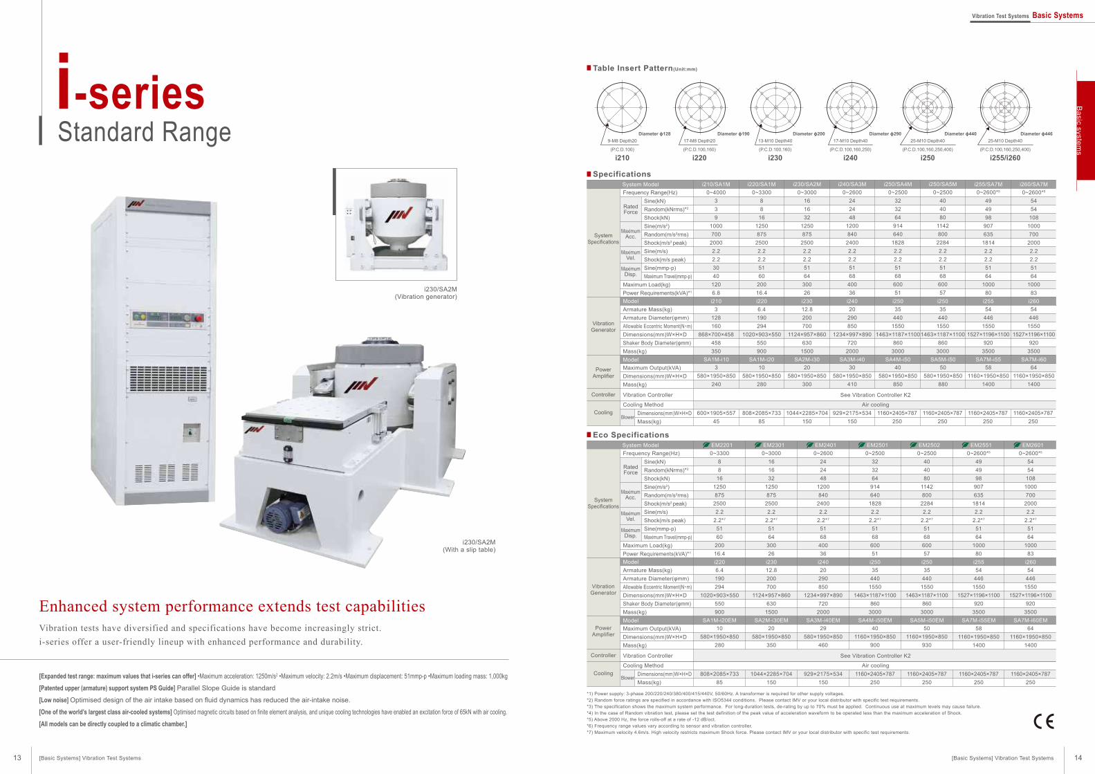
Enhanced system performance extends test capabilities
Table Insert Pattern(Unit:mm)
Specifications
Vibration tests have diversified and specifications have become increasingly strict.
i-series offer a user-friendly lineup with enhanced performance and durability.
[Expanded test range: maximum values that i-series can offer] •Maximum acceleration: 1250m/s2 •Maximum velocity: 2.2m/s •Maximum displacement: 51mmp-p •Maximum loading mass: 1,000kg
[Patented upper (armature) support system PS Guide] Parallel Slope Guide is standard
[Low noise] Optimised design of the air intake based on fluid dynamics has reduced the air-intake noise.
[One of the world’s largest class air-cooled systems] Optimised magnetic circuits based on finite element analysis, and unique cooling technologies have enabled an excitation force of 65kN with air cooling.
[All models can be directly coupled to a climatic chamber.]
*1) Power supply: 3-phase 200/220/240/380/400/415/440V, 50/60Hz. A transformer is required for other supply voltages.*2) Random force ratings are specified in accordance with ISO5344 conditions. Please contact IMV or your local distributor with specific test requirements.*3) The specification shows the maximum system performance. For long-duration tests, de-rating by up to 70% must be applied. Continuous use at maximum levels may cause failure.*4) In the case of Random vibration test, please set the test definition of the peak value of acceleration waveform to be operated less than the maximum acceleration of Shock.*5) Above 2000 Hz, the force rolls-off at a rate of -12 dB/oct.*6) Frequency range values vary according to sensor and vibration controller.*7) Maximum velocity 4.6m/s. High velocity restricts maximum Shock force. Please contact IMV or your local distributor with specific test requirements.
i-seriesStandard Range
i230/SA2M(With a slip table)
i230/SA2M(Vibration generator)
Diameter ɸ128 Diameter ɸ190 Diameter ɸ200 Diameter ɸ290 Diameter ɸ440 Diameter ɸ4469-M8 Depth20
i210
17-M8 Depth20
i220
13-M10 Depth40
i230
17-M10 Depth40
i240
25-M10 Depth40
i255/i260
25-M10 Depth40
(P.C.D.100) (P.C.D.100,160) (P.C.D.100,160) (P.C.D.100,160,250) (P.C.D.100,160,250,400)(P.C.D.100,160,250,400)
i250
System Model
Model
Model
SystemSpecifications
VibrationGenerator
PowerAmplifier
Cooling
Controller
Frequency Range(Hz) 0~4000339
1000700
20002.22.23040
1206.8
0~330088
161250875
25002.22.25160
20016.4
i220/SA1M0~3000
161632
1250875
25002.22.25164
30026
i230/SA2M0~2600
242448
1200840
24002.22.25168
40036
i240/SA3M0~2500
323264
914640
18282.22.25168
60051
i250/SA4M0~2500
404080
1142800
22842.22.25168
60057
i250/SA5M0~2600*5
494998
907635
18142.22.25164
100080
i255/SA7M0~2600*5
5454
1081000700
20002.22.25164
100083
i260/SA7Mi210/SA1M
SA1M-i20 SA2M-i30 SA3M-i40 SA4M-i50 SA5M-i50 SA7M-i55 SA7M-i60SA1M-i10
i220 i230 i240 i250 i250 i255 i260i210
Maximum Load(kg)Power Requirements(kVA)*1
See Vibration Controller K2
Air cooling
Armature Mass(kg)Armature Diameter(φmm)Allowable Eccentric Moment(N・m)Dimensions(mm)W×H×DShaker Body Diameter(φmm)Mass(kg)
Vibration Controller
Cooling Method
Blower
Maximum Output(kVA)Dimensions(mm)W×H×DMass(kg)
Dimensions(mm)W×H×DMass(kg)
Sine(kN)Random(kNrms)*2
Shock(kN)Sine(m/s2)Random(m/s2rms)Shock(m/s2 peak)Sine(m/s)Shock(m/s peak)Sine(mmp-p)Maximum Travel(mmp-p)
RatedForce
MaximumAcc.
MaximumVel.
MaximumDisp.
3128160
868×700×458458350
6.4190294
1020×903×550550900
12.8200700
1124×957×860630
1500
20290850
1234×997×890720
2000
35440
15501463×1187×1100
8603000
35440
15501463×1187×1100
8603000
54446
15501527×1196×1100
9203500
54446
15501527×1196×1100
9203500
3580×1950×850
240
10580×1950×850
280
20580×1950×850
300
30580×1950×850
410
40580×1950×850
850
50580×1950×850
880
581160×1950×850
1400
641160×1950×850
1400
600×1905×55745
808×2085×73385
1044×2285×704150
929×2175×534150
1160×2405×787250
1160×2405×787250
1160×2405×787250
1160×2405×787250
Eco Specifications
System Model
Model
Model
SystemSpecifications
VibrationGenerator
PowerAmplifier
Cooling
Controller
RatedForce
MaximumAcc.
MaximumVel.
MaximumDisp.
Frequency Range(Hz) 0~330088
161250875
25002.2
2.2*7
5160
20016.4
0~3000161632
1250875
25002.2
2.2*7
5164
30026
EM23010~2600
242448
1200840
24002.2
2.2*7
5168
40036
EM24010~2500
323264
914640
18282.2
2.2*7
5168
60051
EM25010~2500
404080
1142800
22842.2
2.2*7
5168
60057
EM25020~2600*5
494998
907635
18142.2
2.2*7
5164
100080
EM25510~2600*5
5454
1081000700
20002.2
2.2*7
5164
100083
EM2601EM2201
SA2M-i30EM SA3M-i40EM SA4M-i50EM SA5M-i50EM SA7M-i55EM SA7M-i60EMSA1M-i20EM
i230 i240 i250 i250 i255 i260i220
Maximum Load(kg)Power Requirements(kVA)*1
See Vibration Controller K2
Air cooling
Armature Mass(kg)Armature Diameter(φmm)Allowable Eccentric Moment(N・m)Dimensions(mm)W×H×DShaker Body Diameter(φmm)Mass(kg)
Vibration Controller
Cooling Method
Blower
Maximum Output(kVA)Dimensions(mm)W×H×DMass(kg)
Dimensions(mm)W×H×DMass(kg)
Sine(kN)Random(kNrms)*2
Shock(kN)Sine(m/s2)Random(m/s2rms)Shock(m/s2 peak)Sine(m/s)Shock(m/s peak)Sine(mmp-p)Maximum Travel(mmp-p)
6.4190294
1020×903×550550900
12.8200700
1124×957×860630
1500
20290850
1234×997×890720
2000
35440
15501463×1187×1100
8603000
35440
15501463×1187×1100
8603000
54446
15501527×1196×1100
9203500
54446
15501527×1196×1100
9203500
10580×1950×850
280
20580×1950×850
350
29580×1950×850
460
401160×1950×850
900
501160×1950×850
930
581160×1950×850
1400
641160×1950×850
1400
808×2085×73385
1044×2285×704150
929×2175×534150
1160×2405×787250
1160×2405×787250
1160×2405×787250
1160×2405×787250
[Basic Systems] Vibration Test Systems [Basic Systems] Vibration Test Systems
Basic system
s
13 14
Vibration Test Systems Basic Systems
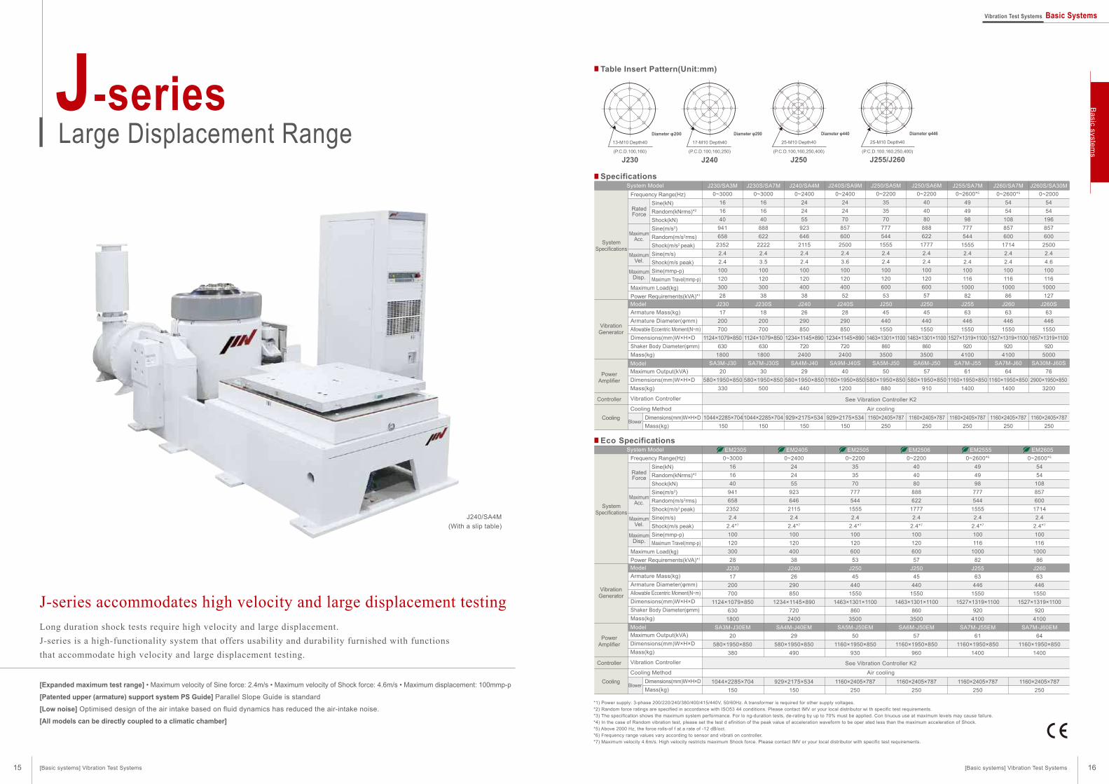
J-series accommodates high velocity and large displacement testing
Table Insert Pattern(Unit:mm)
Specifications
Long duration shock tests require high velocity and large displacement.
J-series is a high-functionality system that offers usability and durability furnished with functions
that accommodate high velocity and large displacement testing.
[Expanded maximum test range] • Maximum velocity of Sine force: 2.4m/s • Maximum velocity of Shock force: 4.6m/s • Maximum displacement: 100mmp-p
[Patented upper (armature) support system PS Guide] Parallel Slope Guide is standard
[Low noise] Optimised design of the air intake based on fluid dynamics has reduced the air-intake noise.
[All models can be directly coupled to a climatic chamber]
*1) Power supply: 3-phase 200/220/240/380/400/415/440V, 50/60Hz. A transformer is required for other supply voltages.*2) Random force ratings are specified in accordance with ISO53 44 conditions. Please contact IMV or your local distributor wi th specific test requirements.*3) The specification shows the maximum system performance. For lo ng-duration tests, de-rating by up to 70% must be applied. Con tinuous use at maximum levels may cause failure.*4) In the case of Random vibration test, please set the test d efinition of the peak value of acceleration waveform to be oper ated less than the maximum acceleration of Shock.*5) Above 2000 Hz, the force rolls-of f at a rate of -12 dB/oct.*6) Frequency range values vary according to sensor and vibrati on controller.*7) Maximum velocity 4.6m/s. High velocity restricts maximum Shock force. Please contact IMV or your local distributor with specific test requirements.
J-seriesLarge Displacement Range
J240/SA4M(With a slip table)
0~3000161640
941658
23522.42.410012030028
0~3000161640
888622
22222.43.510012030038
J230S/SA7M0~2400
242455
92364621152.42.410012040038
J240/SA4M0~2400
242470
857600
25002.43.610012040052
J240S/SA9M0~2200
353570
777544
15552.42.410012060053
J250/SA5M0~2200
404080
888622
17772.42.410012060057
J250/SA6M0~2600*5
494998
777544
15552.42.4100116
100082
J255/SA7M0~2600*5
5454
108857600
17142.42.4100116
100086
J260/SA7MJ230/SA3M
SA7M-J30S SA4M-J40 SA9M-J40S SA5M-J50 SA6M-J50 SA7M-J55 SA7M-J60SA3M-J30
J230S J240 J240S J250 J250 J255 J260J23017
200700
1124×1079×850630
1800
18200700
1124×1079×850630
1800
26290850
1234×1145×890720
2400
28290850
1234×1145×890720
2400
45440
15501463×1301×1100
8603500
45440
15501463×1301×1100
8603500
63446
15501527×1319×1100
9204100
63446
15501527×1319×1100
9204100
20580×1950×850
330
30580×1950×850
500
29580×1950×850
440
401160×1950×850
1200
50580×1950×850
880
57580×1950×850
910
611160×1950×850
1400
641160×1950×850
1400
0~20005454
196857600
25002.44.6100116
1000127
J260S/SA30M
SA30M-J60S
J260S63
4461550
1657×1319×1100920
5000
762900×1950×850
3200
1044×2285×704150
1044×2285×704150
929×2175×534150
929×2175×534150
1160×2405×787250
1160×2405×787250
1160×2405×787250
1160×2405×787250
1160×2405×787250
Eco Specifications
0~3000161640
941658
23522.4
2.4*7
10012030028
0~2400242455
92364621152.4
2.4*7
10012040038
0~2200353570
777544
15552.4
2.4*7
10012060053
0~2200404080
888622
17772.4
2.4*7
10012060057
0~2600*5
494998
777544
15552.4
2.4*7
100116
100082
0~2600*5
5454
108857600
17142.4
2.4*7
100116
100086
EM2305 EM2405 EM2505 EM2506 EM2555 EM2605
SA3M-J30EM SA4M-J40EM SA5M-J50EM SA6M-J50EM SA7M-J55EM SA7M-J60EM
J230 J240 J250 J250 J255 J26017
200700
1124×1079×850630
1800
26290850
1234×1145×890720
2400
45440
15501463×1301×1100
8603500
45440
15501463×1301×1100
8603500
63446
15501527×1319×1100
9204100
63446
15501527×1319×1100
9204100
20580×1950×850
380
29580×1950×850
490
501160×1950×850
930
571160×1950×850
960
611160×1950×850
1400
641160×1950×850
1400
1044×2285×704150
929×2175×534150
1160×2405×787250
1160×2405×787250
1160×2405×787250
1160×2405×787250
13-M10 Depth40
J230
17-M10 Depth40
J240
25-M10 Depth40
J250
25-M10 Depth40
J255/J260
Diameter φ200 Diameter φ290 Diameter φ440 Diameter φ446
System Model
Maximum Output(kVA)Dimensions(mm)W×H×DMass(kg)
Vibration Controller
Cooling MethodDimensions(mm)W×H×DMass(kg)
Model
Model
SystemSpecifications
VibrationGenerator
Cooling
PowerAmplifier
Controller
Blower
System Model
See Vibration Controller K2
Air cooling
Frequency Range(Hz)
Maximum Load(kg)Power Requirements(kVA)*1
Sine(kN)Random(kNrms)*2
Shock(kN)Sine(m/s2)Random(m/s2rms)Shock(m/s2 peak)Sine(m/s)Shock(m/s peak)Sine(mmp-p)Maximum Travel(mmp-p)
RatedForce
MaximumAcc.
MaximumVel.
MaximumDisp.
Armature Mass(kg)Armature Diameter(φmm)Allowable Eccentric Moment(N・m)Dimensions(mm)W×H×DShaker Body Diameter(φmm)Mass(kg)
Maximum Output(kVA)Dimensions(mm)W×H×DMass(kg)
Vibration Controller
Cooling MethodDimensions(mm)W×H×DMass(kg)
Model
Model
SystemSpecifications
VibrationGenerator
Cooling
PowerAmplifier
Controller
Blower
See Vibration Controller K2
Air cooling
Frequency Range(Hz)
Maximum Load(kg)Power Requirements(kVA)*1
Sine(kN)Random(kNrms)*2
Shock(kN)Sine(m/s2)Random(m/s2rms)Shock(m/s2 peak)Sine(m/s)Shock(m/s peak)Sine(mmp-p)Maximum Travel(mmp-p)
RatedForce
MaximumAcc.
MaximumVel.
MaximumDisp.
Armature Mass(kg)Armature Diameter(φmm)Allowable Eccentric Moment(N・m)Dimensions(mm)W×H×DShaker Body Diameter(φmm)Mass(kg)
(P.C.D.100,160) (P.C.D.100,160,250) (P.C.D.100,160,250,400) (P.C.D.100,160,250,400)
15 16[Basic systems] Vibration Test Systems [Basic systems] Vibration Test Systems
Basic system
sVibration Test Systems Basic Systems
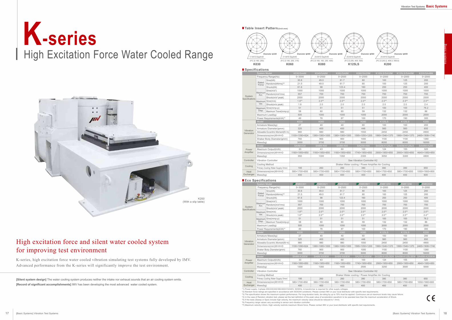
High excitation force and silent water cooled system
for improving test environment
Table Insert Pattern(Unit:mm)
Specifications
K-series, high excitation force water cooled vibration simulating test systems fully developed by IMV.
Advanced performance from the K-series will significantly improve the test environment.
[Silent system design] The water cooling system produces neither the intake nor exhaust sounds that an air cooling system emits.
[Record of significant accomplishments] IMV has been developing the most advanced water cooled system.
*1) Power supply: 3-phase 200/220/240/380/400/415/440V, 50/60Hz. A transformer is required for other supply voltages.
*2) Random force ratings are specified in accordance with ISO5344 conditions. Please contact IMV or your local distributor with specific test requirements.
*3) The specification shows the maximum system performance. For long-duration tests, de-rating by up to 70% must be applied. Continuous use at maximum levels may cause failure.
*4) In the case of Random vibration test, please set the test definition of the peak value of acceleration waveform to be operated less than the maximum acceleration of Shock.
*5) If the tests (Sweep or Spot) include high velocity, the maximum velocity value should be reduced to 1.4m/s.
*6) Frequency range values vary according to sensor and vibration controller.
*7) Maximum velocity 4.6m/s. High velocity restricts maximum Shock force. Please contact IMV or your local distributor with specific test requirements.
K-seriesHigh Excitation Force Water Cooled Range
K200(With a slip table)
Model
Model
HeatExchanger
See Vibration Controller K2
Shaker:Water cooling / Power Amplifier:Air Cooling
Armature Mass(kg)
Armature Diameter(φmm)Allowable Eccentric Moment(N・m)
Dimensions(mm)W×H×D
Shaker Body Diameter(φmm)Mass(kg)
Vibration Controller
Cooling Method
Maximum Output(kVA)
Dimensions(mm)W×H×D
Mass(kg)
Primary Cooling Water Supply(ℓ/min)
0~3000
30.8
21.5
61.6
1000
557
2000
1.8*5
1.8
51
58
500
49
K030/SA4M
SA4M-K30
K030
27
320
980
1100×1090×824
760
3000
33
1160×1950×850
950
195
580×1700×850
400
0~2500
49.0
49.0
98
1000
700
2000
2.0*5
2.0
51
60
1000
76
K049/SA6M
SA6M-K60
K060
40
400
980
1380×1085×1000
900
3700
43
1160×1950×850
1300
260
580×1700×850
400
0~2500
61.7
61.7
123.4
1000
700
2000
2.0*5
2.0
51
60
1000
87
K062/SA8M
SA8M-K60
K060
40
400
980
1380×1085×1000
900
3700
60
1160×1950×850
1350
260
580×1700×850
400
0~2500
80
80
160
1000
700
2000
2.0*5
2.0
51
59
1000
100
K080/SA20M
SA20M-K80
K080
60
446
1550
1595×1050×1200
1000
5000
100
1740×1950×850
2300
390
580×1700×850
400
0~2000
100
100
200
1000
700
2000
2.0*5
2.0
100
132
2000
170
K100LS/SA32M
SA32M-K125LS
K125LS
100
560
2450
1990×1546×1370
1100
8000
124
2900×1950×850
3050
390
580×1700×850
400
0~2000
125
125
250
1000
700
2000
2.0*5
2.0
100
132
2000
190
K125LS/SA40M
SA40M-K125LS
K125LS
100
560
2450
1990×1546×1370
1100
8000
155
2900×1950×850
3300
390
580×1700×850
400
0~2000
200
200
400
1000
700
2000
2.0*5
2.4
76.2
86
2000
300
K200/SA48M
SA48M-K200
K200
200
650
4900
2465×1908×1740
1260
16000
320
4640×1950×850
4800
650
1050×1900×800
600
System Model
Model
Model
Frequency Range(Hz)
Maximum Load(kg)
Power Requirements(kVA)*1
See Vibration Controller K2
Shaker:Water cooling / Power Amplifier:Air Cooling
Armature Mass(kg)
Armature Diameter(φmm)Allowable Eccentric Moment(N・m)
Dimensions(mm)W×H×D
Shaker Body Diameter(φmm)Mass(kg)
Vibration Controller
Cooling Method
Primary Cooling Water Supply(ℓ/min)
Maximum Output(kVA)
Dimensions(mm)W×H×D
Mass(kg)
Sine(kN)
Random(kNrms)*2
Shock(kN)
Sine(m/s2)
Random(m/s2rms)
Shock(m/s2 peak)
Sine(m/s)
Shock(m/s peak)
Sine(mmp-p)
Maximum Travel(mmp-p)
Eco Specifications
17-M10 Depth40 21-M16 Depth40
K060
25-M10 Depth40
K080
25-M16 Depth40
K125LS
25-M16 Depth40
K200
Diameter ɸ320 Diameter ɸ400 Diameter ɸ446 Diameter ɸ560 Diameter ɸ650
0~3000
30.8
21.5
61.6
1000
557
2000
1.8*5
1.8*7
51
58
500
49
EMK0301
SA4M-K30EM
K030
27
320
980
1100×1090×824
760
3000
33
1160×1950×850
1300
195
580×1700×850
400
0~2500
49.0
49.0
98
1000
700
2000
2.0*5
2.0*7
51
60
1000
76
EMK0621
SA6M-K60EM
K060
40
400
980
1380×1085×1000
900
3700
43
1160×1950×850
1350
260
580×1700×850
400
0~2500
61.7
61.7
123.4
1000
700
2000
2.0*5
2.0*7
51
60
1000
87
EMK0622
SA8M-K60EM
K060
40
400
980
1380×1085×1000
900
3700
60
1160×1950×850
1400
260
580×1700×850
400
0~2500
80
80
160
1000
700
2000
2.0*5
2.0*7
51
59
1000
100
EMK0801
SA20M-K80EM
K080
60
446
1550
1595×1050×1200
1000
5000
100
1740×1950×850
2500
390
580×1700×850
400
0~2000
100
100
200
1000
700
2000
2.0*5
2.0*7
100
132
2000
170
EMK1255
SA32M-K125LSEM
K125LS
100
560
2450
1990×1546×1370
1100
8000
124
2900×1950×850
3250
390
580×1700×850
400
0~2000
125
125
250
1000
700
2000
2.0*5
2.0*7
100
132
2000
190
EMK1256
SA40M-K125LSEM
K125LS
100
560
2450
1990×1546×1370
1100
8000
155
2900×1950×850
3500
390
580×1700×850
400
0~2000
200
200
400
1000
700
2000
2.0*5
2.4*7
76.2
86
2000
300
EMK2002
SA48M-K200EM
K200
200
650
4900
2465×1908×1740
1260
16000
320
4640×1950×850
5000
650
1050×1900×800
600
SystemSpecifications
VibrationGenerator
PowerAmplifier
Cooling
Controller
HeatExchanger
SystemSpecifications
VibrationGenerator
PowerAmplifier
Cooling
Controller
Frequency Range(Hz)
Maximum Load(kg)
Power Requirements(kVA)*1
Sine(kN)
Random(kNrms)*2
Shock(kN)
Sine(m/s2)
Random(m/s2rms)
Shock(m/s2 peak)
Sine(m/s)
Shock(m/s peak)
Sine(mmp-p)
Maximum Travel(mmp-p)
RatedForce
MaximumAcc.
MaximumVel.
MaximumDisp.
RatedForce
MaximumAcc.
MaximumVel.
MaximumDisp.
System Model
Dimensions(mm)W×H×D
Mass(kg)
Dimensions(mm)W×H×D
Mass(kg)
[Basic Systems] Vibration Test Systems
K030(P.C.D.160, 250) (P.C.D.100, 200, 315) (P.C.D.100, 160, 250, 400) (P.C.D.250, 400, 500) (P.C.D.203.2, 406.4, 558.8)
[Basic Systems] Vibration Test Systems
Ba
sic system
s
17 18
Vibration Test Systems Basic Systems

Silent type appropriate for abnormal noise inspection
Table Insert Pattern(Unit:mm)
Compact and silent design, but also powerful for full-scale test.
[Silent design employing a built-in cooling fan] DC powered cooling fan is built-into the shaker. Natural air cooling is also used when the cooling fan is
stopped for silent operation. (with a reduction in performance)
m-seriesLow Acoustic Noise and Compact Range
m030/MA1
Head expander Slip table
2-axis changeover vibration test system
Accessories
A pair of carrying handles
Easily moved safely by one or
two operators.
Removable *m030 and m060
only
Air pump
The vibration table height is
adjusted to compensate for
payload weight using an air
pump.
m-series multi-axis system
A range of small-size systems, including 2-axis and 3-axis
simultaneous systems, employing the popular m-series
vibration generators and patented Integrated Cross
Coupling Bearing Unit (ICCU) multi-axis armature / load
support technology.
Compact design
Low noise(ideal for squeak-rattle testing)
High precision measurement
Low power consumption
*1) Frequency range values vary according to sensor and vibration controller.
*2) The displacement at the lower limit of frequency (1000Hz) and maximum acceleration (200m/s2) is so small that there is no certified value.
*3) Power supply: single-phase 100V or 200-240V, 50/60Hz. A transformer is required for other supply voltages.
MaximumAcc.
Ratedforce
Specifications
Model
Model
Frequency Range(Hz)*1
Maximum Velocity(m/s)
Maximum Displacement(mmp-p)
Maximum Load(kg)
Power Requirements(kVA)*3
m030/MA1System Model
Armature Support Method
Armature Mass(kg)
Armature Diameter(φmm)
Dimensions(mm)
Mass(kg)
Maximum Output(kVA)
Dimensions(mm)W×H×D
Mass(kg)
Cooling Method
Blower
Sine(N)
Random(Nrms)
Shock(N)
No Load(m/s2)
0.5kg Load(m/s2)
1.0kg Load(m/s2)
m030H/MA1
1000~10000
380
266
380
200
158
131
― *2
― *2
15
0.5
MA1
m030H
Rubber spring
1.9
65
φ190×H274
22
1.0
430×149×430
25
0~3000
300
210
300
500
272
187
1.6
26
15
0.4
MA1
m030
Diaphragm spring
0.6
114
φ190×H240
22
1.0
430×149×430
25
m060/MA1
0~3000
600
420
600
500
352
272
1.6
30
15
0.7
MA1
m060
Diaphragm spring
1.2
114
φ230×H281
40
1.0
430×149×430
25
m120/MA1
0~2000
1200
840
1200
500
413
352
1.6
30
120
1.1
MA1
m120
Diaphragm spring
2.4
174
410×410×H372
110
1.0
430×149×430
25
Housed in vibration generator
Rated force
Table size
Frequency range
Maximum acceleration
Maximum displacement
Maximum payload
Cooling method
System noise
Weight
Power requirements
1200N
200×200mm
~500Hz
30m/s2
10mmp-p
10kg
Air cooling
55dB(A)
Approx. 730kg
3φ200V, 4kVA
9-M6 Depth10
m030
Diameter ɸ114
9-M6 Depth10
m060
Diameter ɸ114
17-M6 Depth10
m120
Diameter ɸ174
5-M6 Depth15
m030H
Diameter ɸ65
System specifications
TBH-2
TBH-3
200×200
315×315
~500
~500
Slip table
Model Dimensions(mm) Upper frequency(Hz)
4
7.5
m030
4
7.5
m060
5.5
9
m120
Option
TBV-125- -A
TBV-200- -A
TBV-315- -A
*TBV-400- -A
125×125×t20
200×200×t20
315×315×t30
400×400×t35
0.9
2.5
8.5
14.4
~2000
~1500
~1000
~600
Head expander
Model Dimensions(mm) Mass(kg) Upper frequency(Hz) m030 m060 m120
“-A” at the end of model number shows that material is aluminum alloy.
Add the vibration generator type where “ ” is shown.
* The supplementary guidance system using linear bearings is used with the vibration generator when combined with the head expander.
Supplementary guidance system (GDP)
Air cooling
(P.C.D.100) (P.C.D.100) (P.C.D.100, 160) (P.C.D.50)
SystemSpecifications
VibrationGenerator
PowerAmplifier
Cooling
*
*
*
[Basic Systems] Vibration Test Systems [Basic Systems] Vibration Test Systems
Ba
sic system
s
19 20
Vibration Test Systems Basic Systems

Options for use with vertical tables
Guide system, additional air spring
Optional Units
Head expanders
Where the size of the specimen exceeds the dimensions of the vibration generator table a head-expander should be used. Generally, the
maximum usable frequency is reduced as the size of specimen increases. The head-expander should be selected based on specimen size and
maximum test frequency required. Properties of the standard range of head-expanders is shown in the table.
Head expander (flat surface type)
Cubic fixture
The specimen can be fastened to the top or the side face of the cubic fixture where testing in each axis is required.
Two types of cubic fixture are available. Type A has fixing holes on each face, Type B has specimen mounting plates which attach to the cubic frame.
Vibration generatorAir spring
guide system
The following option increases the allowable overturning moment of the head expander.
Additional guide system Enabling larger or off-centre specimens to be tested.
Additional air spring Providing additional load support to accommodate higher specimen
& fixture mass.
*Some models do not support the options above
High-frequency model
A head-expander having exceptionally low mass and special dual conical shape giving excellent damping.
Type BType A
Z
Z
Z
Y
Y
YX X
X
specimen mounting plates
VIBRATION
specimen mounting plates
Cubic fixture
Z
Z
Y
X
X
Z
Cubic fixture
VIBRATION
Y
Y
X
300
1000
1000
1150 1400
1450
1400
1150 1450
350
300 500
500
700
900
700 900
950
750
750 950
550
550
35010
0
200
200
100
100
100
Model
TBV-125- -A
TBV-125- -M
TBV-315- -A
TBV-315- -M
TBV-400- -A
TBV-400- -M
TBV-500- -A
TBV-500- -M
TBV-630- -A
TBV-630- -M
TBV-800- -A
TBV-800- -M
TBV-1000- -A
TBV-1000- -M
TBV-1200- -A
TBV-1200- -M
TBV-1500- -A
TBV-1500- -M
0.9
0.6
8.5
5.8
13
9
15
10.4
19
12.5
45
30
110
78
180
120
300
200
~2000
~1000
~600
~500
~360
~350
~350
~200
~200
125×125t 20
315×315t 30
400×400t 30
500×500t 40
630×630t 45
800×800t 70
1000×1000t 110
1200×1200t 125
1500×1500t 200
Model
TBV-125- -A
TBV-125- -M
TBV-315- -A
TBV-315- -M
TBV-400- -A
TBV-400- -M
TBV-500- -A
TBV-500- -M
TBV-630- -A
TBV-630- -M
TBV-800- -A
TBV-800- -M
TBV-1000- -A
TBV-1000- -M
TBV-1200- -A
TBV-1200- -M
TBV-1500- -A
TBV-1500- -M
Dimensions(mm)
Mass(kg)
Maximum frequency
(Hz) i210 i220 i230 i240 i250 i260
K030 K060
K-series
K080
i260L J230 J240 J250 J260
J-seriesi-series
Model names ending with “A” indicate aluminum body and “M” indicate magnesium alloy.
Add the vibration generator type where “ ” is shown.
*The data shown refers to the IMV standard range. Custom designs can also be
supplied.
0.9
0.6
8.5
5.8
13
9
15
10.4
19
12.5
45
30
110
78
180
120
300
200
~2000
~1000
~600
~500
~360
~350
~350
~200
~200
125×125t 20
315×315t 30
400×400t 30
500×500t 40
630×630t 45
800×800t 70
1000×1000t 110
1200×1200t 125
1500×1500t 200
Dimensions(mm)
Mass(kg)
Maximum frequency
(Hz)
6
11
17
30
27
50
45
80
90
160
135
240
750
1500
300
600
200
400
150
300
120
240
100
200
M10 Depth25
M10 Depth25
M10 Depth25
M10 Depth25
M10 Depth25
M10 Depth25
M10 Depth25
M10 Depth25
M10 Depth25
M10 Depth25
M10 Depth25
M10 Depth25
100mmPitch
100mmPitch
100mmPitch
100mmPitch
100mmPitch
100mmPitch
100mmPitch
100mmPitch
200mmPitch
200mmPitch
200mmPitch
200mmPitch
350×350×t 33
350×350×t 65
550×550×t 30
550×550×t 60
750×750×t 38
750×750×t 38
950×950×t 45
950×950×t 90
1150×1150×t 60
1150×1150×t 120
1450×1450×t 80
1450×1450×t 160
Model
TBV-350- -A-L
TBV-350- -A-H
TBV-550- -A-L
TBV-550- -A-H
TBV-750- -A-L
TBV-750- -A-H
TBV-950- -A-L
TBV-950- -A-H
TBV-1150- -A-L
TBV-1150- -A-H
TBV-1450- -A-L
TBV-1450- -A-H
Dimensions(mm)
Mass(kg)
Maximum frequency
(Hz)
Specimen mounting screw Screw pitch
Model names ending with “A” indicate aluminum body.
Add the vibration generator type where “ ” is shown.
Model names ending with “A” indicate aluminum body and “M” indicate magnesium alloy. Add the vibration generator type where “ ” is shown.
5.5
4
6.5
4.6
8
5.6
13.5
9.5
20
14
~2000
~2000
~1000
~650
~400
150×150×150
160×160×160
200×200×200
250×250×250
300×300×300
3.5
2.5
4
2.8
10
7
20
14
20
14
~2000
~2000
~2000
~1000
~600
TCJ-B150-P-A
TCJ-B150-P-M
TCJ-B160-P-A
TCJ-B160-P-M
TCJ-B200-P-A
TCJ-B200-P-M
TCJ-B250-P-A
TCJ-B250-P-M
TCJ-B300-P-A
TCJ-B300-P-M
1.5
1.1
1.7
1.3
3.5
2.5
4.5
3.2
6.5
4.5
150×150×150
160×160×160
200×200×200
250×250×250
300×300×300
Model
TCJ-A150- -A
TCJ-A150- -M
TCJ-A160- -A
TCJ-A160- -M
TCJ-A200- -A
TCJ-A200- -M
TCJ-A250- -A
TCJ-A250- -M
TCJ-A300- -A
TCJ-A300- -M
Dimensions (mm) Mass (kg)
Cubic fixture (Type A)
Maximum frequency(Hz) Model
TCJ-B150- -A
TCJ-B150- -M
TCJ-B160- -A
TCJ-B160- -M
TCJ-B200- -A
TCJ-B200- -M
TCJ-B250- -A
TCJ-B250- -M
TCJ-B300- -A
TCJ-B300- -M
Dimensions (mm) Mass (kg)
Cubic fixture (Type B) specimen mounting plates
Maximum frequency(Hz) Model Mass (kg)
Head expanders and cubic fixtures
TBV-630
630 630
TBV-800
800 800
TBV-315
315 315
TBV-400
400 400
TBV-500
500 500
TBV-1000
1000 1000
TBV-1200
1200 1200
TBV-1500
1500 1500
[Basic Systems] Vibration Test Systems [Basic Systems] Vibration Test Systems
Ba
sic system
s
21 22
Vibration Test Systems Basic Systems

T-Film bearing range
Optional Units
Slip table *Except for A-series
A slip table is required for testing a specimen in its horizontal axis, or when a heavy specimen is to be tested.
Slip tables are designed to achieve low friction in the driven axis, while supporting heavy loads and introducing minimal waveform distortion.
The T-Film bearing from Team Corporation is probably the most advanced design
of linear bearing available to the vibration-test industry.
The slip table employs a number of bearings, each consisting of a U.S.-patented
bearing element and hydro-static oil film.
T-Film bearings provide excellent vibration waveform linearity and are considered
to be the best solution for the aerospace industry and research establishments.
Option for slip table
IMV can offer three types of slip table to cater for a wide range of requirements.
Type and features of slip table
The design uses a V-shaped guide system beneath the slip table,
preventing transverse and vertical motion.
This design of slip table has been used widely and is recognised as
offering excellent performance over a wide frequency range.
They achieve low distortion even at high frequency.
‘V’-guided range
This range of slip tables uses multiple hydro-static bearing blocks beneath
the slip plate.
It offers high stiffness to overturning moments, restraining transverse and
vertical movement.
Operation is good over a wide frequency range.
The range accommodates different sized tables.
Hydro-static bearing range
Rotation reduction gearing
A reduction gearing unit enabling easier reconfiguration of the
vibration generator.
Preinstalled in i240, i250, i260, J240, J250, J260 and K-series
Motor drive rotation
Powered rotation of the vibration generator.
The motor-driven rotation can be optionally installed on systems
equipped with reduction gearing.
Principle
Features
Additionalinformation
Table is supported on an oil film
Low frictionHydraulic power unit is not needed
Not suitable for high acceleration tests that create large over-turning moments
Table is supported by hydro-static bearings and an air film
Compatible with large over-turning momentTable size can be changed
Requires a separate hydraulic unit.Installation space for the hydraulic unit is necessary.
Table is supported by hydro-static bearings and an air film
Compatible with large over-turning momentLow cross-axis movement and low distortion
Requires a separate hydraulic unit. Installation space for the hydraulic unit is necessary.
Hydro-static bearing range‘V’-guided range T-Film bearing range
HB-5500mm×500mm
800kg
ModelDimensions
Maximum load
Vibrationgenerator
HB-6630mm×630mm
1200kg
HB-8800mm×800mm
1600kg
HB-101000mm×1000mm
2000kg
Mass(kg)
Maximumfrequency
(Hz)
Mass(kg)
Maximumfrequency
(Hz)
Mass(kg)
Maximumfrequency
(Hz)
Mass(kg)
Maximumfrequency
(Hz)
TBH-5500mm×500mm
200kg
ModelDimensions
Maximum load
Vibrationgenerator
TBH-6630mm×630mm
300kg
TBH-8800mm×800mm
400kg
TBH-101000mm×1000mm
500kg
Mass(kg)
Maximumfrequency
(Hz)
Mass(kg)
Maximumfrequency
(Hz)
Mass(kg)
Maximumfrequency
(Hz)
Mass(kg)
Maximumfrequency
(Hz)
i210
i220
i230
i240
i250
i255
i260
J230
J240
J250
J255
J260
K030
K060
K080
K125
60
63
65
68
78
78
78
68
70
83
83
83
68
93
78
103
53
33
60―
2000
―
70
45
2000
2000
―
65
98
65
―
2000
2000
―
100
143
100
―
1250
1250
2500
2500
2500
2500
2000
2000
2000
1600
1600
1600
1600
1600
2000
2000
2000
2000
70
83
83
88
95
95
95
88
90
100
100
100
88
108
95
118
2000
2000
2000
2000
2000
2000
2000
1600
1600
1600
1600
1600
2000
2000
2000
2000
115
118
120
123
133
133
133
125
130
143
143
143
123
145
133
155
2000
2000
2000
2000
2000
2000
2000
1250
1250
1250
1250
1250
2000
2000
2000
2000
165
168
170
173
180
180
180
175
178
188
188
188
173
193
180
205
1250
1250
1250
1250
1250
1250
1250
1000
1000
1000
1000
1000
1250
1250
1250
1250
i210
i220
i230
i240
i250
i255
i260
K030
K060
K080
33 2500 45
17011580
2000
*The data shown refers to the IMV standard range.
Custom designs can also be supplied.
Slip table
[Basic Systems] Vibration Test Systems [Basic Systems] Vibration Test Systems
Ba
sic system
s
23 24
Vibration Test Systems Basic Systems
Allowable eccentric moment verification test
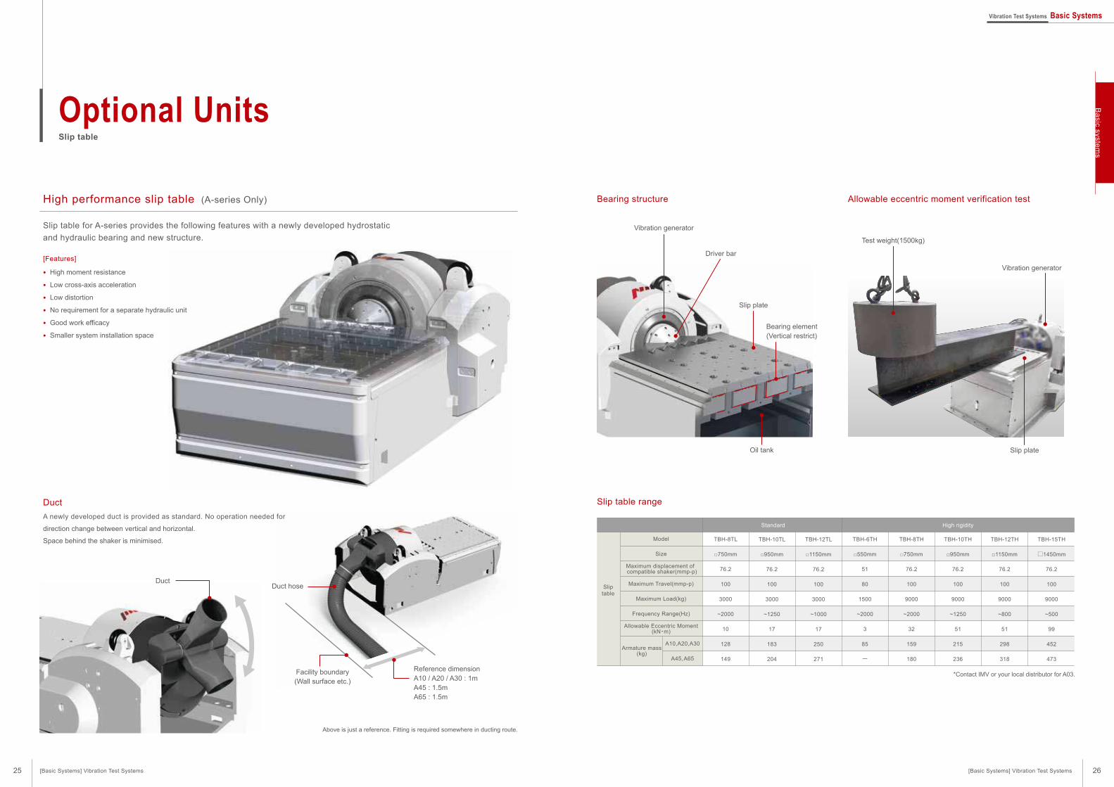
Slip table for A-series provides the following features with a newly developed hydrostatic
and hydraulic bearing and new structure.
[Features]
● High moment resistance
● Low cross-axis acceleration
● Low distortion
● No requirement for a separate hydraulic unit
● Good work efficacy
● Smaller system installation space
Bearing structure
Slip table range
Sliptable
Model
Size
Maximum displacement of compatible shaker(mmp-p)
Maximum Travel(mmp-p)
Maximum Load(kg)
Frequency Range(Hz)
Allowable Eccentric Moment(kN・m)
Standard High rigidity
TBH-8TL
□750mm
76.2
100
3000
~2000
10
128
149
TBH-6TH
□550mm
51
80
1500
~2000
3
85
ー
TBH-8TH
□750mm
76.2
100
9000
~2000
32
159
180
TBH-10TH
□950mm
76.2
100
9000
~1250
51
215
236
TBH-12TH
□1150mm
76.2
100
9000
~800
51
298
318
TBH-15TH
□1450mm
76.2
100
9000
~500
99
452
473
TBH-10TL
□950mm
76.2
100
3000
~1250
17
183
204
TBH-12TL
□1150mm
76.2
100
3000
~1000
17
250
271
Armature mass(kg)
A10,A20,A30
A45, A65
Duct
A newly developed duct is provided as standard. No operation needed for
direction change between vertical and horizontal.
Space behind the shaker is minimised.
Duct
Above is just a reference. Fitting is required somewhere in ducting route.
Duct hose
Reference dimensionA10 / A20 / A30 : 1mA45 : 1.5mA65 : 1.5m
Facility boundary(Wall surface etc.)
Vibration generator
Test weight(1500kg)
Slip plate
Slip plate
Driver bar
Vibration generator
Oil tank
Bearing element(Vertical restrict)
High performance slip table (A-series Only)
*Contact IMV or your local distributor for A03.
[Basic Systems] Vibration Test Systems [Basic Systems] Vibration Test Systems
Ba
sic system
s
25 26
Optional UnitsSlip table
Vibration Test Systems Basic Systems

Horizontal operation Changing orientation Vertical operation
Optional UnitsFixture, Vibration Isolation, Air spring base, load spreader base
Optional UnitsSound-proof enclosure, cooling ducting, flexible duct
Fixture
IMV has a range of fixtures, such as cube and ‘L’-shaped types, to suit most applications.
Custom fixtures are supplied, designed and analysed using finite-element modeling to ensure best performance.
Sound-proof enclosure
A sound-proof enclosure for the cooling blower reduces
noise in installations where the blower cannot be located
outside the work area.
Cooling ducting
The standard arrangement for air-cooled systems is
to install the blower outside the work area.
The air drawn into the work area replacing air
extracted by the blower can be a problem.
Ducting the input air from outside eliminates the
changes in ambient pressure and temperature
caused by the cooling air flow.
Flexible duct
Rotating the vibration generator to operate in the vertical or horizontal axis can place stress on the cooling hose.
The flexible duct fittings mounted on the vibration generator rotate to accommodate both orientations.
Vibration Isolation
Additional isolation mounts are available to reduce the effects of vibration on the floor and adjacent equipment.
These are simple to install by placing
under the vibration generator.
Insulation pad
Reinforcement
The weight of the vibration generator can
be distributed over a larger area where
the maximum allowable floor loading is
limited.
Load spreader base
Air springs placed under each
corner of the frame support the
vibration generator and are an
excellent way to isolate vibration
above about 5Hz.
Air spring
[Basic Systems] Vibration Test Systems [Basic Systems] Vibration Test Systems
Ba
sic system
s
27 28
Vibration Test Systems Basic Systems
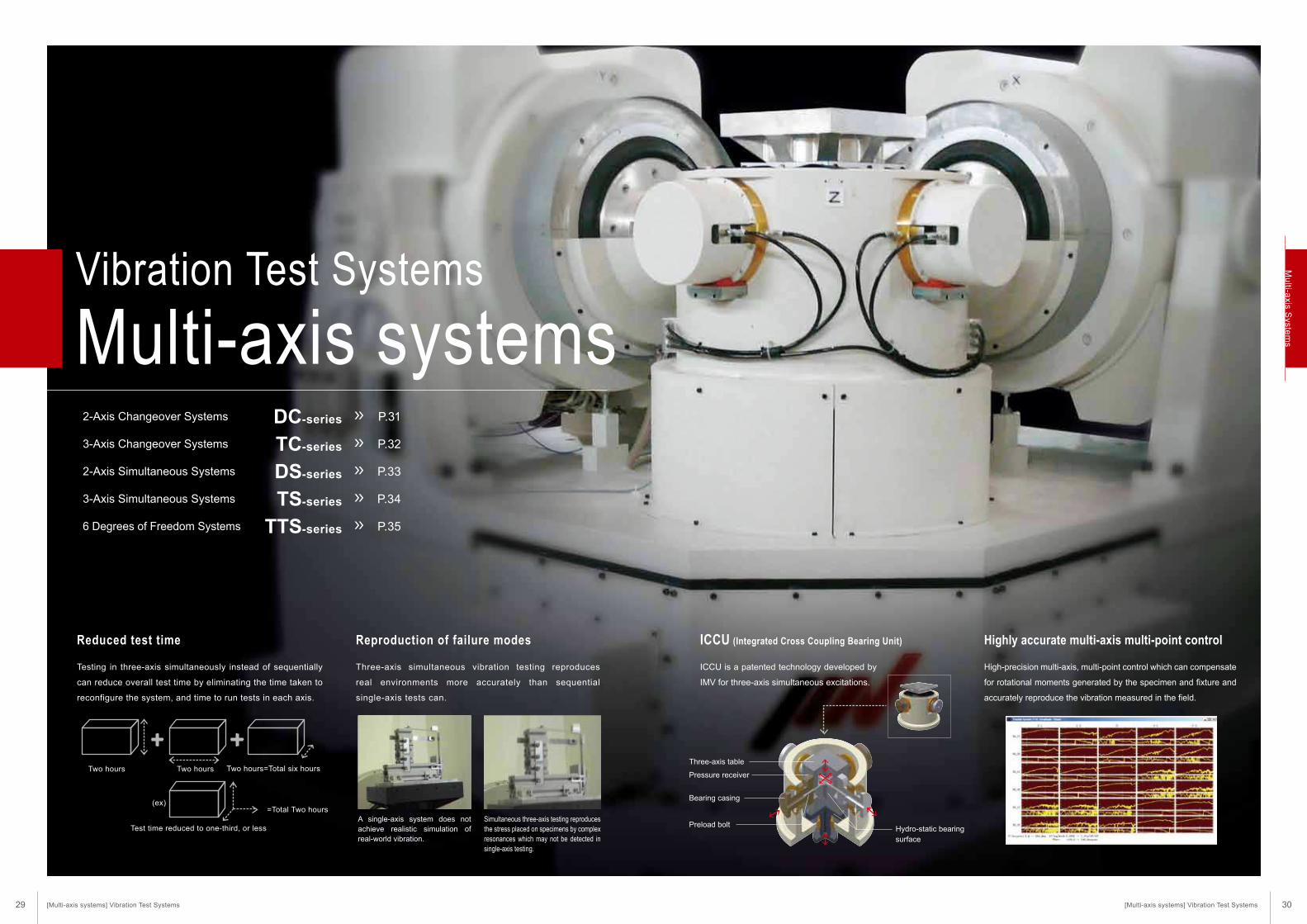
Vibration Test Systems
Multi-axis systems2-Axis Changeover Systems
3-Axis Changeover Systems
2-Axis Simultaneous Systems
3-Axis Simultaneous Systems
6 Degrees of Freedom Systems
Three-axis simultaneous vibration testing reproduces
real environments more accurately than sequential
single-axis tests can.
ICCU is a patented technology developed by
IMV for three-axis simultaneous excitations.
Testing in three-axis simultaneously instead of sequentially
can reduce overall test time by eliminating the time taken to
reconfigure the system, and time to run tests in each axis.
ICCU (Integrated Cross Coupling Bearing Unit)
High-precision multi-axis, multi-point control which can compensate
for rotational moments generated by the specimen and fixture and
accurately reproduce the vibration measured in the field.
Highly accurate multi-axis multi-point controlReproduction of failure modesReduced test time
Two hours Two hours Two hours=Total six hours
(ex)
Test time reduced to one-third, or less
=Total Two hoursA single-axis system does not achieve realistic simulation of real-world vibration.
Simultaneous three-axis testing reproduces the stress placed on specimens by complex resonances which may not be detected in single-axis testing.
DC-series
TC-series
DS-series
TS-series
TTS-series
P.31
P.32
P.33
P.34
P.35
Three-axis table
Pressure receiver
Bearing casing
Preload boltHydro-static bearing
surface
[Multi-axis systems] Vibration Test Systems [Multi-axis systems] Vibration Test Systems29 30
Mu
lti-axis S
ystem
s
System Model
Table Size(mm)
Maximum Acceleration(m/s2)
Maximum Velocity(m/s)
Maximum Displacement(mmp-p)
Armature Mass(kg)
Maximum Load(kg)
Power Requirements(kVA)
Cooling Water(L/min)
Sine(kN)
Random(kN)
Shock(kN)
Horizontal(Hz)
Vertical(Hz)
System Model
Table Size(mm)
Maximum Acceleration(m/s2)
Maximum Velocity(m/s)
Maximum Displacement(mmp-p)
Armature Mass(kg)
Maximum Load(kg)
Power Requirements(kVA)
Cooling Water(L/min)
Sine(kN)
Random(kN)
Shock(kN)
Horizontal(Hz)
Vertical(Hz)
SystemSpecifications
SystemSpecifications
RatedForce
MaximumFrequency
RatedForce
MaximumFrequency
TC-3000-6H
*Depending on the reference PSD or other operating conditions such as the specimen, one part of the controlled response may deviate from the reference PSD
Specifications
400
9.8
4.9
14.7
98
1.0
51
100
1,000
1,000
100
27
–
TC-1000-4H
600
9.8
4.9
14.7
65
1.0
51
150
800
1,000
100
27
–
TC-1000-6H
800
9.8
4.9
14.7
42
1.0
51
230
700
700
200
27
–
TC-1000-8H
1000
9.8
4.9
14.7
33
1.0
51
290
350
500
200
27
–
TC-1000-10M
500
19.6
9.8
29.4
163
1.0
51
120
800
800
200
43
–
TC-2000-5H
800
19.6
9.8
29.4
98
1.0
51
200
500
800
300
43
–
TC-2000-8M
1000
19.6
9.8
29.4
65
1.0
51
300
350
500
500
43
–
TC-2000-10M
1500
19.6
9.8
29.4
30
0.9
51
640
250
350
500
43
–
TC-2000-15M
500
29.4
14.7
44.1
196
1.0
51
150
800
800
200
52
–
TC-3000-5H
800
29.4
14.7
44.1
113
1.0
51
260
500
800
300
52
–
TC-3000-8M
1000
29.4
14.7
44.1
73
1.0
51
400
350
500
500
52
–
TC-3000-10M
1500
29.4
14.7
44.1
43
0.9
51
680
250
350
500
52
–
TC-3000-15M
600
49
29.4
73.5
306
1.0
51
160
800
1,000
300
77
195
TC-5000-6H
800
49
29.4
73.5
222
1.0
51
220
700
800
300
77
195
TC-5000-8H
1000
49
24.5
58.8
158
0.9
51
310
350
500
500
75
190
TC-5000-10M
1500
49
24.5
58.8
67
0.9
51
730
250
350
700
75
190
TC-5000-15M
600
61.7
37
92.5
342
1.0
51
180
800
1,000
300
93
230
TC-6000-6H
800
61.7
37
92.5
257
1.0
51
240
700
800
300
93
230
TC-6000-8H
1000
61.7
30.8
74
199
0.9
51
310
350
500
500
91
225
TC-6000-10M
1500
61.7
30.8
74
84
0.9
51
730
250
350
700
91
225
TC-6000-15M
DC-2000-5H
*Depending on the reference PSD or other operating conditions such as the specimen, one part of the controlled response may deviate from the reference PSD
System Model
Table Size(mm)
Maximum Acceleration(m/s2)
Maximum Velocity(m/s)
Maximum Displacement(mmp-p)
Armature Mass(kg)
Maximum Load(kg)
Power Requirements(kVA)
Cooling Water(L/min)
Sine(kN)
Random(kN)
Shock(kN)
Horizontal(Hz)
Vertical(Hz)
1000
29.4
14.7
44.1
91
1.0
51
320
350
500
500
52
–
DC-3000-10M
1500
29.4
14.7
44.1
47
0.9
51
620
250
350
500
52
–
DC-3000-15M
600
49
29.4
73.5
350
1.0
51
140
800
1,000
300
75
195
DC-5000-6H
800
49
29.4
73.5
204
1.0
51
240
700
800
300
75
195
DC-5000-8H
1000
49
24.5
58.8
163
0.9
51
300
350
500
500
73
190
DC-5000-10M
1500
49
24.5
58.8
59
0.9
51
820
250
350
700
73
190
DC-5000-15M
600
61.7
37
92.5
385
1.0
51
160
800
1,000
300
93
230
DC-6000-6H
800
61.7
37
92.5
268
1.0
51
230
700
800
300
93
230
DC-6000-8H
1000
61.7
30.8
74
102
0.9
51
600
350
500
500
91
225
DC-6000-10M
1500
61.7
30.8
74
75
0.9
51
820
250
350
700
91
225
DC-6000-15M
Specifications
System Model
Table Size(mm)
Maximum Acceleration(m/s2)
Maximum Velocity(m/s)
Maximum Displacement(mmp-p)
Armature Mass(kg)
Maximum Load(kg)
Power Requirements(kVA)
Cooling Water(L/min)
Sine(kN)
Random(kN)
Shock(kN)
Horizontal(Hz)
Vertical(Hz)
400
9.8
4.9
14.7
108
1.0
51
90
1,000
1,000
100
25
–
DC-1000-4H
600
9.8
4.9
14.7
75
1.0
51
130
800
1,000
100
25
–
DC-1000-6H
800
9.8
4.9
14.7
54
1.0
51
180
700
700
200
25
–
DC-1000-8H
1000
9.8
4.9
14.7
32
1.0
51
300
350
500
200
25
–
DC-1000-10M
500
19.6
9.8
29.4
150
1.0
51
130
800
800
200
43
–
DC-2000-5H
800
19.6
9.8
29.4
81
1.0
51
240
500
800
300
43
–
DC-2000-8M
1000
19.6
9.8
29.4
67
1.0
51
290
350
500
500
43
–
DC-2000-10M
1500
19.6
9.8
29.4
28
0.9
51
680
250
350
500
43
–
DC-2000-15M
500
29.4
14.7
44.1
196
1.0
51
150
800
800
200
52
–
DC-3000-5H
800
29.4
14.7
44.1
140
1.0
51
210
500
800
300
52
–
DC-3000-8M
SystemSpecifications
SystemSpecifications
RatedForce
MaximumFrequency
RatedForce
MaximumFrequency
31 32
Mu
lti-axis S
ystem
sVibration Test Systems Multi-axis Systems
DC-series2-Axis Changeover Systems
TC-series3-Axis Changeover Systems
[Multi-axis systems] Vibration Test Systems [Multi-axis systems] Vibration Test Systems

System Model
Table Size(mm)
Maximum Acceleration(m/s2)
Maximum Velocity(m/s)
Maximum Displacement(mmp-p)
Armature Mass(kg)
Maximum Load(kg)
Power Requirements(kVA)
Cooling Water(L/min)
Sine(kN)
Random(kN)
Shock(kN)
Horizontal(Hz)
Vertical(Hz)
System Model
Table Size(mm)
Maximum Acceleration(m/s2)
Maximum Velocity(m/s)
Maximum Displacement(mmp-p)
Armature Mass(kg)
Maximum Load(kg)
Power Requirements(kVA)
Cooling Water(L/min)
Sine(kN)
Random(kN)
Shock(kN)
Horizontal(Hz)
Vertical(Hz)
SystemSpecifications
SystemSpecifications
RatedForce
MaximumFrequency
RatedForce
MaximumFrequency
*Depending on the reference PSD or other operating conditions such as the specimen, one part of the controlled response may deviate from the reference PSD
Specifications
*Depending on the reference PSD or other operating conditions such as the specimen, one part of the controlled response may deviate from the reference PSD
System Model
Table Size(mm)
Maximum Acceleration(m/s2)
Maximum Velocity(m/s)
Maximum Displacement(mmp-p)
Armature Mass(kg)
Maximum Load(kg)
Power Requirements(kVA)
Cooling Water(L/min)
Sine(kN)
Random(kN)
Shock(kN)
Horizontal(Hz)
Vertical(Hz)
Specifications
System Model
Table Size(mm)
Maximum Acceleration(m/s2)
Maximum Velocity(m/s)
Maximum Displacement(mmp-p)
Armature Mass(kg)
Maximum Load(kg)
Power Requirements(kVA)
Cooling Water(L/min)
Sine(kN)
Random(kN)
Shock(kN)
Horizontal(Hz)
Vertical(Hz)
SystemSpecifications
SystemSpecifications
RatedForce
MaximumFrequency
RatedForce
MaximumFrequency
DS-2000-4H
DS-series2-Axis Simultaneous Systems
TS-series3-Axis Simultaneous Systems
400
9.8
4.9
14.7
98
1.0
51
100
1,000
1,000
100
41
–
TS-1000-4H
600
9.8
4.9
14.7
65
1.0
51
150
800
1,000
100
41
–
TS-1000-6H
800
9.8
4.9
14.7
42
1.0
51
230
700
700
200
41
–
TS-1000-8H
1000
9.8
4.9
14.7
33
1.0
51
290
350
500
200
41
–
TS-1000-10M
500
19.6
9.8
29.4
163
1.0
51
120
800
800
200
94
–
TS-2000-5H
800
19.6
9.8
29.4
98
1.0
51
200
500
800
300
94
–
TS-2000-8M
1000
19.6
9.8
29.4
65
1.0
51
300
350
500
500
94
–
TS-2000-10M
1500
19.6
9.8
29.4
30
0.9
51
640
250
350
500
94
–
TS-2000-15M
500
29.4
14.7
44.1
196
1.0
51
150
800
800
200
110
–
TS-3000-5H
800
29.4
14.7
44.1
113
1.0
51
260
500
800
300
110
–
TS-3000-8M
1000
29.4
14.7
44.1
73
1.0
51
400
350
500
500
110
–
TS-3000-10M
1500
29.4
14.7
44.1
43
0.9
51
680
250
350
500
110
–
TS-3000-15M
600
49
29.4
73.5
306
1.0
51
160
800
1,000
300
149
550
TS-5000-6H
800
49
29.4
73.5
222
1.0
51
220
700
800
300
149
550
TS-5000-8H
1000
49
24.5
58.8
158
0.9
51
310
350
500
500
153
530
TS-5000-10M
1500
49
24.5
58.8
67
0.9
51
730
250
350
700
153
530
TS-5000-15M
600
61.7
37
92.5
342
1.0
51
180
800
1,000
300
182
650
TS-6000-6H
800
61.7
37
92.5
257
1.0
51
240
700
800
300
182
650
TS-6000-8H
1000
61.7
30.8
74
199
0.9
51
310
350
500
500
182
640
TS-6000-10M
1500
61.7
30.8
74
84
0.9
51
730
250
350
700
186
640
TS-6000-15M
1000
29.4
14.7
44.1
91
1.0
51
320
350
500
500
76
–
DS-3000-10M
1500
29.4
14.7
44.1
47
0.9
51
620
250
350
500
76
–
DS-3000-15M
600
49
29.4
73.5
350
1.0
51
140
800
1,000
300
104
370
DS-5000-6H
800
49
29.4
73.5
204
1.0
51
240
700
800
300
104
370
DS-5000-8H
1000
49
24.5
58.8
163
0.9
51
300
350
500
500
106
360
DS-5000-10M
1500
49
24.5
58.8
59
0.9
51
820
250
350
700
106
360
DS-5000-15M
600
61.7
37
92.5
385
1.0
51
160
800
1,000
300
126
440
DS-6000-6H
800
61.7
37
92.5
268
1.0
51
230
700
800
300
126
440
DS-6000-8H
1000
61.7
30.8
74
102
0.9
51
600
350
500
500
128
430
DS-6000-10M
1500
61.7
30.8
74
75
0.9
51
820
250
350
700
128
430
DS-6000-15M
400
9.8
4.9
14.7
108
1.0
51
90
1,000
1,000
100
30
–
DS-1000-4H
600
9.8
4.9
14.7
75
1.0
51
130
800
1,000
100
30
–
DS-1000-6H
800
9.8
4.9
14.7
54
1.0
51
180
700
700
200
30
–
DS-1000-8H
1000
9.8
4.9
14.7
32
1.0
51
300
350
500
200
30
–
DS-1000-10M
500
19.6
9.8
29.4
150
1.0
51
130
800
800
200
66
–
DS-2000-5H
800
19.6
9.8
29.4
81
1.0
51
240
500
800
300
66
–
DS-2000-8M
1000
19.6
9.8
29.4
67
1.0
51
290
350
500
500
66
–
DS-2000-10M
1500
19.6
9.8
29.4
28
0.9
51
680
250
350
500
66
–
DS-2000-15M
500
29.4
14.7
44.1
196
1.0
51
150
800
800
200
76
–
DS-3000-5H
800
29.4
14.7
44.1
140
1.0
51
210
500
800
300
76
–
DS-3000-8M
TS-1000-4H
33 34
Mu
lti-axis S
ystem
s
[Multi-axis systems] Vibration Test Systems [Multi-axis systems] Vibration Test Systems
Vibration Test Systems Multi-axis Systems

Ride comfort evaluation system
The addition of rotational motion to a three-axis system enables 6 degree-of freedom testing, as is required for vehicle seat evaluation, for
example.
X axisExcitation direction Y axis Z axis
3.9
150
1
Rated Force(kN)
Maximum displacement(mmp-p)
Frequency Range(Hz)
Table Size(mm)
Vibration Generator
7.8
150
1~100
1800×1800
2
16
100
4
Large-scale 6 DOF vibration test system
A total of 10 vibration generators (6 vertical and 4 horizontal) and a 4000mm by 3500mm large size table allow the simultaneous 6 DOF vibra-
tion testing. This versatile platform is ideal for testing large items such as railway carriage components.
X axisExcitation direction Y axis Z axis
80
2
Rated Force(kN)
Maximum displacement(mmp-p)
Frequency Range(Hz)
Table Size(mm)
Vibration Generator
48
51
2~150
4000×3500
2
96
6
TTS-series6 Degrees of Freedom Systems
6 degrees of freedom systems
At least 6 vibration shakers are located in 3D space with
integrated control and can create 6 degrees of freedom motion (3
translation degrees of freedom and 3 rotating degrees).
In addition to X, Y, Z axis motion, rotational motion, Roll, Pitch and
Yaw is also possible utilising spherical bearings.
Using electro dynamic vibration generators, IMV systems can
reproduce waveforms which have components in a wide
frequency range with a high degree of accuracy. System mainte-
nance is easy. Systems comprise at least six vibration generators
to act along orthogonal axes and also to generate the roll, pitch
and yaw components of vibration. A spherical bearing is used to
allow the rotational motion. By using electrodynamic vibration
generators the system can operate over a wide frequency range
with a high degree of accuracy. System maintenance is straight-
forward.
(Per 1 system)
(Per 1 system)
(Per 1 system)
6 DOF simultaneous squeak and rattle test system for vehicle seats
Air-cooled vibration test system for the evaluation of squeak and rattle noise from an instrument panel or other car interior assemblies.
X axisExcitation direction Y axis Z axis
1600
2
Rated Force(N)
Maximum displacement(mmp-p)
Frequency Range(Hz)
Table Size(mm)
Vibration Generator
1600
30
5~100
1500×3500
2
3200
4
Check the movieon You Tube
Yaw
X
Y
Z
Pitch
Roll
Check the movieon You Tube
35 36
Mu
lti-axis S
ystem
s
[Multi-axis systems] Vibration Test Systems [Multi-axis systems] Vibration Test Systems
Vibration Test Systems Multi-axis Systems
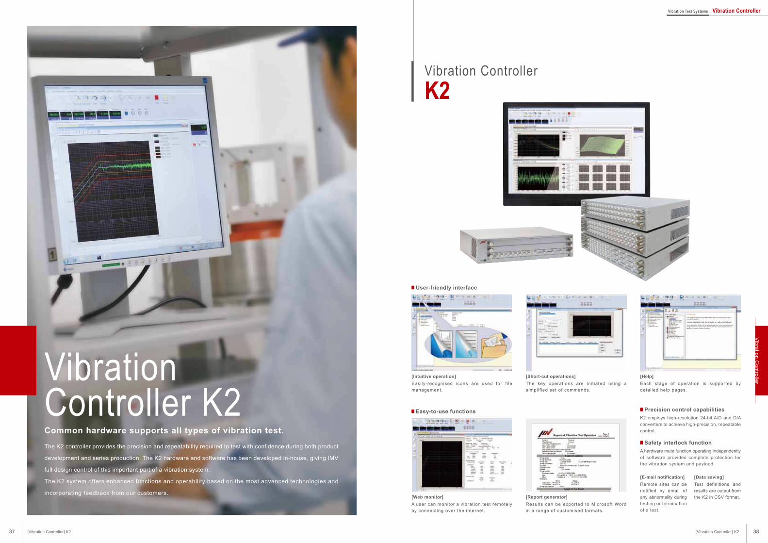
[Intuitive operation]
Easily-recognised icons are used for fi le
management.
[Short-cut operations]
The key operations are initiated using a
simplified set of commands.
[Web monitor]
A user can monitor a vibration test remotely
by connecting over the internet.
[Report generator]
Results can be exported to Microsoft Word
in a range of customised formats.
[Help]
Each stage of operation is supported by
detailed help pages.
K2 employs high-resolution 24-bit A/D and D/A
converters to achieve high-precision, repeatable
control.
A hardware mute function operating independently
of software provides complete protection for
the vibration system and payload.
[E-mail notification]
Remote sites can be
notified by email of
any abnormality during
testing or termination
of a test.
[Data saving]
Test definitions and
results are output from
the K2 in CSV format.
Common hardware supports all types of vibration test.
VibrationController K2
Vibration Controller
K2
User-friendly interface
Easy-to-use functions Precision control capabilities
Safety interlock functionThe K2 controller provides the precision and repeatability required to test with confidence during both product
development and series production. The K2 hardware and software has been developed in-house, giving IMV
full design control of this important part of a vibration system.
The K2 system offers enhanced functions and operability based on the most advanced technologies and
incorporating feedback from our customers.
37 38[Vibration Controller] K2
Vibration Test Systems Vibration Controller
[Vibration Controller] K2
Vib
ratio
n C
on
trolle
r
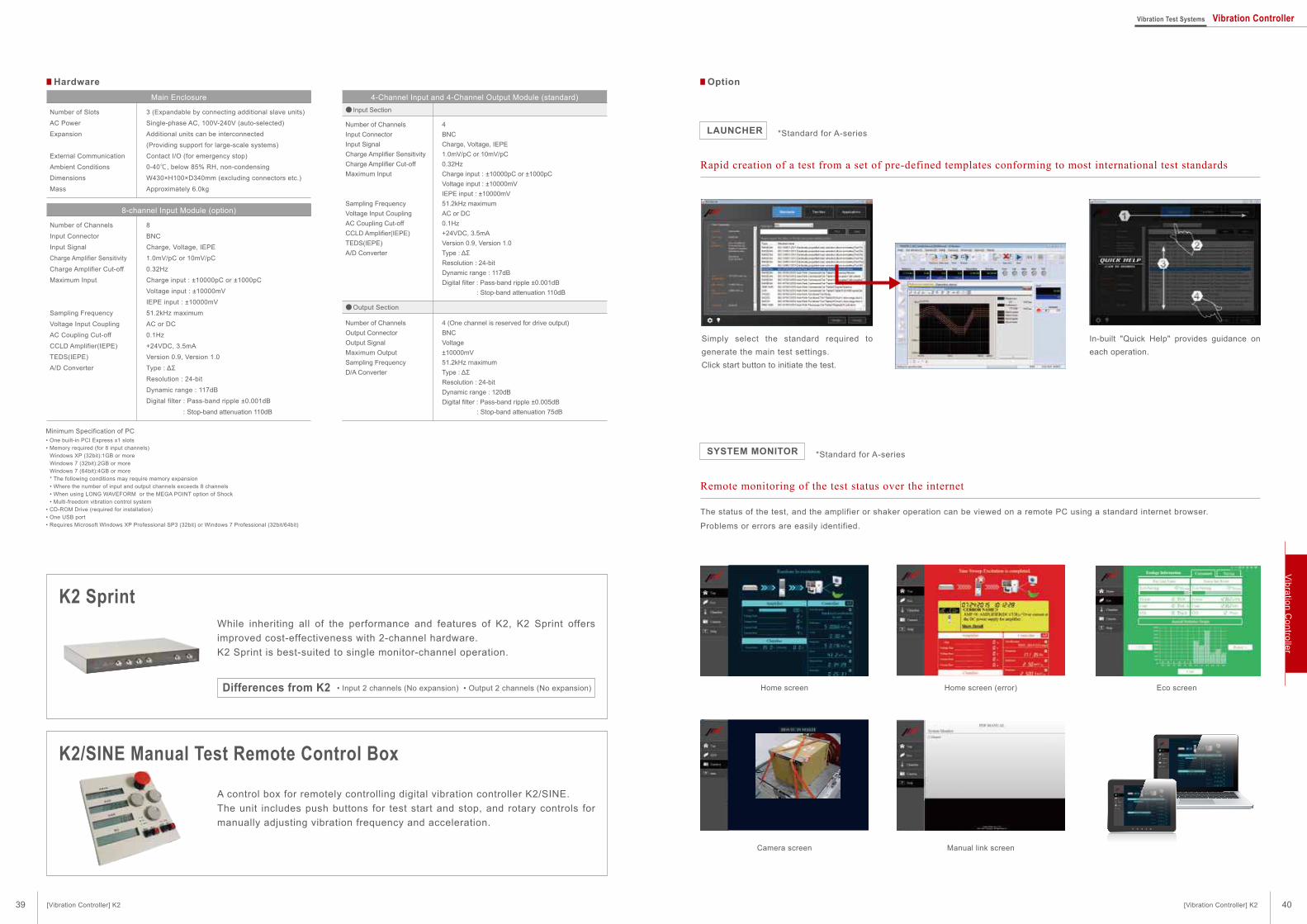
Hardware
Number of Slots
AC Power
Expansion
External Communication
Ambient Conditions
Dimensions
Mass
While inheriting all of the performance and features of K2, K2 Sprint offers
improved cost-effectiveness with 2-channel hardware.
K2 Sprint is best-suited to single monitor-channel operation.
3 (Expandable by connecting additional slave units)
Single-phase AC, 100V-240V (auto-selected)
Additional units can be interconnected
(Providing support for large-scale systems)
Contact I/O (for emergency stop)
0-40℃, below 85% RH, non-condensing
W430×H100×D340mm (excluding connectors etc.)
Approximately 6.0kg
Main Enclosure
Number of Channels
Input Connector
Input Signal
Charge Amplifier Sensitivity
Charge Amplifier Cut-off
Maximum Input
Sampling Frequency
Voltage Input Coupling
AC Coupling Cut-off
CCLD Amplifier(IEPE)
TEDS(IEPE)
A/D Converter
8
BNC
Charge, Voltage, IEPE
1.0mV/pC or 10mV/pC
0.32Hz
Charge input : ±10000pC or ±1000pC
Voltage input : ±10000mV
IEPE input : ±10000mV
51.2kHz maximum
AC or DC
0.1Hz
+24VDC, 3.5mA
Version 0.9, Version 1.0
Type : ΔΣ
Resolution : 24-bit
Dynamic range : 117dB
Digital filter : Pass-band ripple ±0.001dB
: Stop-band attenuation 110dB
8-channel Input Module (option)
Number of Channels
Input Connector
Input Signal
Charge Amplifier Sensitivity
Charge Amplifier Cut-off
Maximum Input
Sampling Frequency
Voltage Input Coupling
AC Coupling Cut-off
CCLD Amplifier(IEPE)
TEDS(IEPE)
A/D Converter
4
BNC
Charge, Voltage, IEPE
1.0mV/pC or 10mV/pC
0.32Hz
Charge input : ±10000pC or ±1000pC
Voltage input : ±10000mV
IEPE input : ±10000mV
51.2kHz maximum
AC or DC
0.1Hz
+24VDC, 3.5mA
Version 0.9, Version 1.0
Type : ΔΣResolution : 24-bit
Dynamic range : 117dB
Digital filter : Pass-band ripple ±0.001dB
: Stop-band attenuation 110dB
4-Channel Input and 4-Channel Output Module (standard)
Minimum Specification of PC• One built-in PCI Express x1 slots• Memory required (for 8 input channels)
Windows XP (32bit):1GB or more
Windows 7 (32bit):2GB or more
Windows 7 (64bit):4GB or more
* The following conditions may require memory expansion
• Where the number of input and output channels exceeds 8 channels• When using LONG WAVEFORM or the MEGA POINT option of Shock• Multi-freedom vibration control system
• CD-ROM Drive (required for installation)• One USB port• Requires Microsoft Windows XP Professional SP3 (32bit) or Windows 7 Professional (32bit/64bit)
Number of Channels
Output Connector
Output Signal
Maximum Output
Sampling Frequency
D/A Converter
4 (One channel is reserved for drive output)
BNC
Voltage
±10000mV
51.2kHz maximum
Type : ΔΣResolution : 24-bit
Dynamic range : 120dB
Digital filter : Pass-band ripple ±0.005dB
: Stop-band attenuation 75dB
Output Section
Input Section
Differences from K2
K2 Sprint
• Input 2 channels (No expansion) • Output 2 channels (No expansion)
K2/SINE Manual Test Remote Control Box
A control box for remotely controlling digital vibration controller K2/SINE.
The unit includes push buttons for test start and stop, and rotary controls for
manually adjusting vibration frequency and acceleration.
Rapid creation of a test from a set of pre-defined templates conforming to most international test standards
Remote monitoring of the test status over the internet
Simply select the standard required to
generate the main test settings.
Click start button to initiate the test.
In-built "Quick Help" provides guidance on
each operation.
The status of the test, and the amplifier or shaker operation can be viewed on a remote PC using a standard internet browser.
Problems or errors are easily identified.
Home screen Home screen (error)
Camera screen Manual link screen
Eco screen
Option
*Standard for A-series
*Standard for A-series
LAUNCHER
SYSTEM MONITOR
39 40
Vib
ratio
n C
on
trolle
r
[Vibration Controller] K2 [Vibration Controller] K2
Vibration Test Systems Vibration Controller
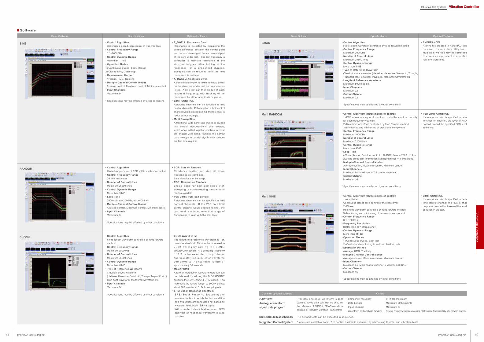
Provides analogue waveform signal
capture, saved data can then be used as
the reference of SHOCK, BMAC waveform
controls or Random vibration PSD control.
• Sampling Frequency
• Data Length
• Input Channel
• Waveform edit/analysis function
51.2kHz maximum
Maximum 5000k points
Maximum 64
Filtering, Frequency transfer processing, PSD transfer, Transmissibility ratio between channels
• Control AlgorithmFinite-length waveform controlled by feed forward method
• Control Frequency RangeMaximum 20000Hz
• Number of Control LinesMaximum 25600 lines
• Control Dynamic RangeMore than 84dB
• Type of Reference WaveformClassical shock waveform (Half-sine, Haversine, Saw-tooth, Triangle,
Trapezoid etc.), Sine beat waveform, Measured waveform etc.
• Length of Reference WaveformMaximum 5000k points
• Input ChannelsMaximum 32
• Output ChannelMaximum 32
* Specifications may be affected by other conditions
• ENDURANCE2A drive file created in K2/BMAC can
be used to run a du rab i l i t y t es t .
Multiple drive files may be combined
to create an equivalent of complex
real-life vibrations.
• Control Algorithm (Three modes of control)1) PSD of random signal closed loop control by spectrum density
for each frequency segment
2) Real-time waveform controlled by feed forward method
3) Monitoring and minimising of cross-axis component
• Control Frequency RangeMaximum 10000Hz
• Number of Control LinesMaximum 3200 lines
• Control Dynamic RangeMore than 90dB
• Loop Time450ms (3-input, 3-output control, 120 DOF, fmax = 2000 Hz, L =
200 line cross-talk information averaging times = 8 times/loop)
• Multiple-Channel Control ModesAverage control, Maximum control, Minimum control
• Input ChannelsMaximum 64 (Maximum of 32 control channels)
• Output ChannelMaximum 16
* Specifications may be affected by other conditions
• PSD LIMIT CONTROLIf a response point is specified to be a
limit control channel, the level of PSD
doesn’t exceed the specified PSD level
in the test.
• Control Algorithm (Three modes of control)1) Amplitude:
Continuous closed-loop control of true rms level
2) Phase:
Real-time waveform controlled by feed forward method
3) Monitoring and minimising of cross-axis component
• Control Frequency Range0.1~10000Hz
• Frequency ResolutionBetter than 10-4 of frequency
• Control Dynamic RangeMore than 114dB
• Operation Modes1) Continuous sweep, Spot test
2) Control and monitoring in various physical units
• Estimation MethodAverage, RMS, Tracking
• Multiple-Channel Control ModesAverage control, Maximum control, Minimum control
• Input ChannelsMaximum 64 (Main control channel is Maximum 32Chs)
• Output ChannelMaximum 16
* Specifications may be affected by other conditions
• LIMIT CONTROLIf a response point is specified to be a
limit control channel, the level of that
response point will not exceed the level
specified in the test.
CAPTURE:Analogue waveform signal data program
SCHEDULER:Test scheduler
Integrated Control System
OutlineCommon optional software
SpecificationsBasic Software Optional Software
BMAC
Multi RANDOM
Multi SINE
Pre-defined tests can be executed in sequence.
Signals are available from K2 to control a climatic chamber, synchronising thermal and vibration tests.
Software
• Control Algorithm Continuous closed-loop control of true rms level
• Control Frequency Range 0.1~20000Hz
• Control Dynamic Range More than 114dB
• Operation Modes1) Continuous sweep, Spot, Manual
2) Closed-loop, Open-loop
• Measurement Method Average, RMS, Tracking
• Multiple-Channel Control Modes Average control, Maximum control, Minimum control
• Input Channels Maximum 64
* Specifications may be affected by other conditions
• R_DWELL: Resonance DwellResonance is detected by measuring the
phase difference between the control point
and the response signal from a resonant part
of the item under test. The test frequency is
controller to maintain resonance as the
structure fatigues. After holding at the
resonance for a pre-defined duration,
sweeping can be resumed, until the next
resonance is detected.
• A_DWELL: Amplitude DwellA transmissibility plot is taken from two points
on the structure under test and resonances
listed. A sine test can then be run at each
resonant frequency, with tracking of the
resonance by either amplitude or phase.
• LIMIT CONTROLResponse channels can be specified as limit
control channels. If the level on a limit control
channel would exceed its limit, the test level is
reduced accordingly.
• Multi Sweep SineA traditional wide-band sine sweep is divided
into several narrower-band sine sweeps,
which when added together combine to cover
the original wide band. Running the narrow
band sweeps in parallel significantly reduces
the test time required.
• Control AlgorithmClosed-loop control of PSD within each spectral line
• Control Frequency Range20 kHz maximum
• Number of Control LinesMaximum 25600 lines
• Control Dynamic RangeMore than 94dB
• Loop Time200ms (fmas=2000Hz, at L=400line)
• Multiple-Channel Control ModesAverage control, Maximum control, Minimum control
• Input Channels Maximum 64
* Specifications may be affected by other conditions
• SOR: Sine on RandomR a n d o m v i b r a t i o n a n d s i n e v i b r a t i o n
frequencies are combined.
Sine vibration can be swept.
• ROR: Random on RandomB r o a d - b a n d r a n d o m c o m b i n e d w i t h
sweeping or non-sweeping narrow-band
random overlaid.
• PSD LIMIT: PSD limit controlResponse channels can be specified as limit
control channels. I f the PSD on a l imit
control channel would exceed its limit, the
test level is reduced over that range of
frequencies to keep with the limit level.
• Control AlgorithmFinite-length waveform controlled by feed forward
method
• Control Frequency RangeMaximum 20000Hz
• Number of Control LinesMaximum 25600 lines
• Control Dynamic RangeMore than 84dB
• Type of Reference WaveformClassical shock waveform
(Half-sine, Haversine, Saw-tooth, Triangle, Trapezoid etc. ),
Sine beat waveform, Measured waveform etc.
• Input Channels Maximum 64
* Specifications may be affected by other conditions
• LONG WAVEFORMThe length of a reference waveform is 16K
points as standard. This can be increased to
2 0 0 K p o i n t s b y a d d i n g t h e L O N G
WAVEFORM option. At a sampling frequency
o f 5 12Hz f o r e xa mp le , t h i s p ro duce s
approximately 6.5 minutes of waveform,
c o m p a r e d t o t h e s t a n d a r d l e n g t h o f
approximately 30 seconds.
• MEGAPOINTA further increase in waveform duration can
be obtained by adding the MEGAPOINT
option to the LONG WAVEFORM option. This
increases the record length to 5000K points,
about 163 minutes at 512-Hz sampling rate.
• SRS: Shock Response SpectrumSRS (Shock Response Spectrum) can
execute the test in which the test condition
and evaluation are conducted not based on
waveform itself, but on SRS analysis.
With standard shock test selected, SRS
analysis of response waveform is also
possible.
SINE
RANDOM
SHOCK
SpecificationsBasic Software Optional software
42
Vib
ratio
n C
on
trolle
r
41 [Vibration Controller] K2 [Vibration Controller] K2
Vibration Test Systems Vibration Controller
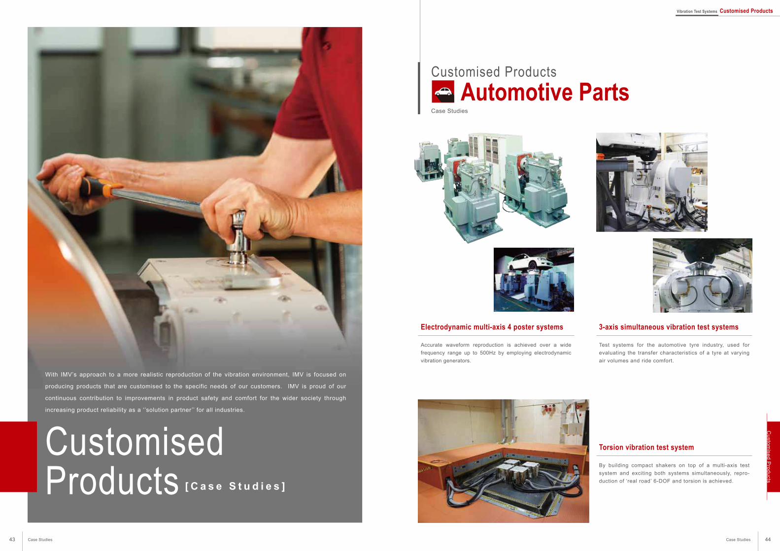
Customised Products
Automotive PartsCase Studies
Electrodynamic multi-axis 4 poster systems
Accurate waveform reproduction is achieved over a wide
frequency range up to 500Hz by employing electrodynamic
vibration generators.
3-axis simultaneous vibration test systems
Test systems for the automotive tyre industry, used for
evaluating the transfer characteristics of a tyre at varying
air volumes and ride comfort.
Torsion vibration test system
By building compact shakers on top of a multi-axis test
system and exciting both systems simultaneously, repro-
duction of ‘real road’ 6-DOF and torsion is achieved.
CustomisedProducts [ C a s e S t u d i e s ]
With IMV’s approach to a more realistic reproduction of the vibration environment, IMV is focused on
producing products that are customised to the specific needs of our customers. IMV is proud of our
continuous contribution to improvements in product safety and comfort for the wider society through
increasing product reliability as a ‘’solution partner’’ for all industries.
44Case Studies
Cu
stom
ised
Pro
du
ctsVibration Test Systems Customised Products
43 Case Studies
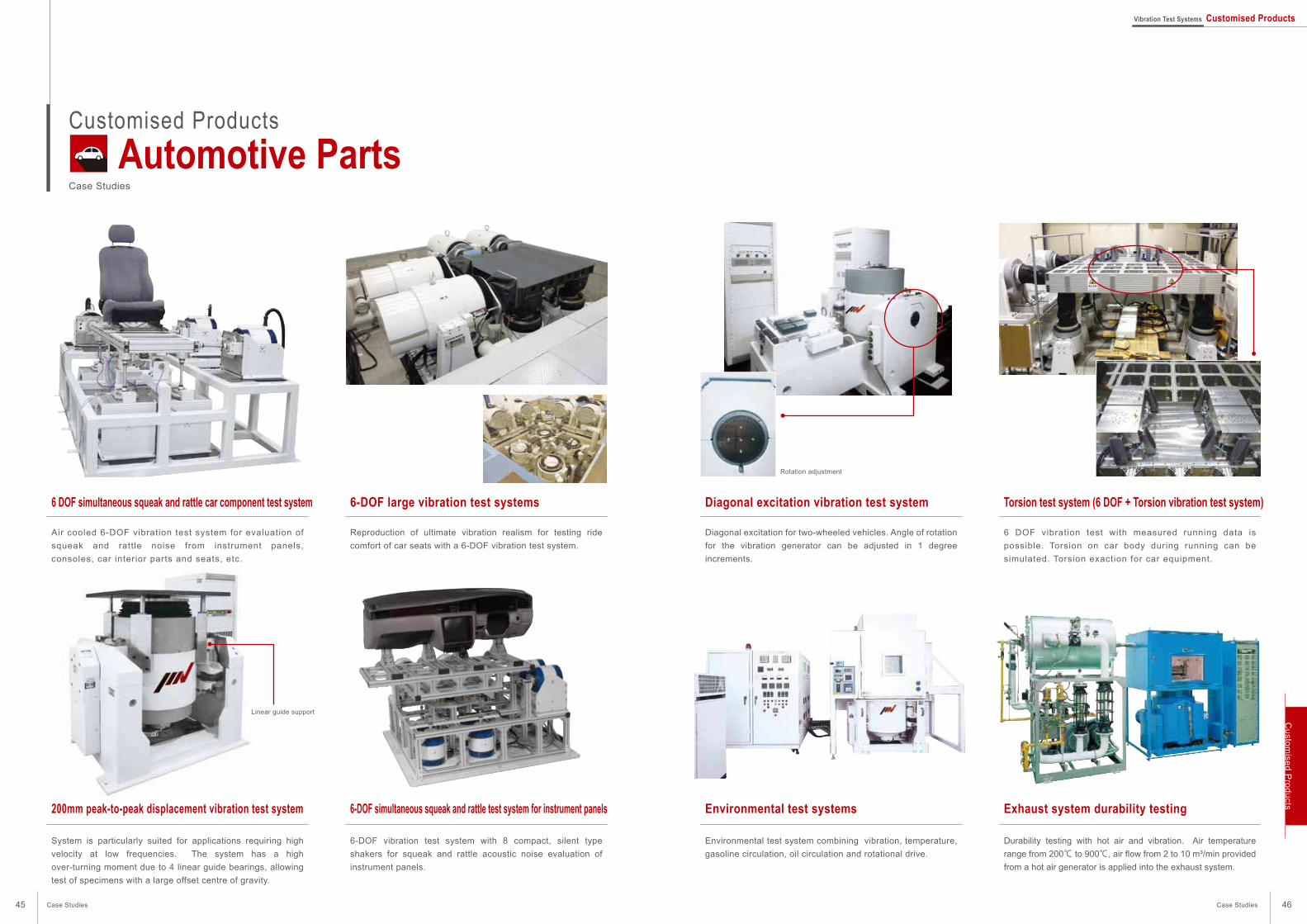
Rotation adjustment
Customised Products
Automotive PartsCase Studies
Diagonal excitation vibration test system
Diagonal excitation for two-wheeled vehicles. Angle of rotation
for the vibration generator can be adjusted in 1 degree
increments.
Torsion test system (6 DOF + Torsion vibration test system)
6 DOF vibration test with measured running data is
possible. Torsion on car body during running can be
simulated. Torsion exaction for car equipment.
Environmental test systems
Environmental test system combining vibration, temperature,
gasoline circulation, oil circulation and rotational drive.
Exhaust system durability testing
Durability testing with hot air and vibration. Air temperature
range from 200℃ to 900℃, air flow from 2 to 10 m³/min provided
from a hot air generator is applied into the exhaust system.
6 DOF simultaneous squeak and rattle car component test system
Air cooled 6-DOF vibration test system for evaluation of
squeak and rattle noise from instrument panels,
consoles, car interior parts and seats, etc.
6-DOF large vibration test systems
Reproduction of ultimate vibration realism for testing ride
comfort of car seats with a 6-DOF vibration test system.
200mm peak-to-peak displacement vibration test system
System is particularly suited for applications requiring high
velocity at low frequencies. The system has a high
over-turning moment due to 4 linear guide bearings, allowing
test of specimens with a large offset centre of gravity.
6-DOF simultaneous squeak and rattle test system for instrument panels
6-DOF vibration test system with 8 compact, silent type
shakers for squeak and rattle acoustic noise evaluation of
instrument panels.
Linear guide support
45 46
Cu
stom
ised
Pro
du
cts
Case StudiesCase Studies
Vibration Test Systems Customised Products
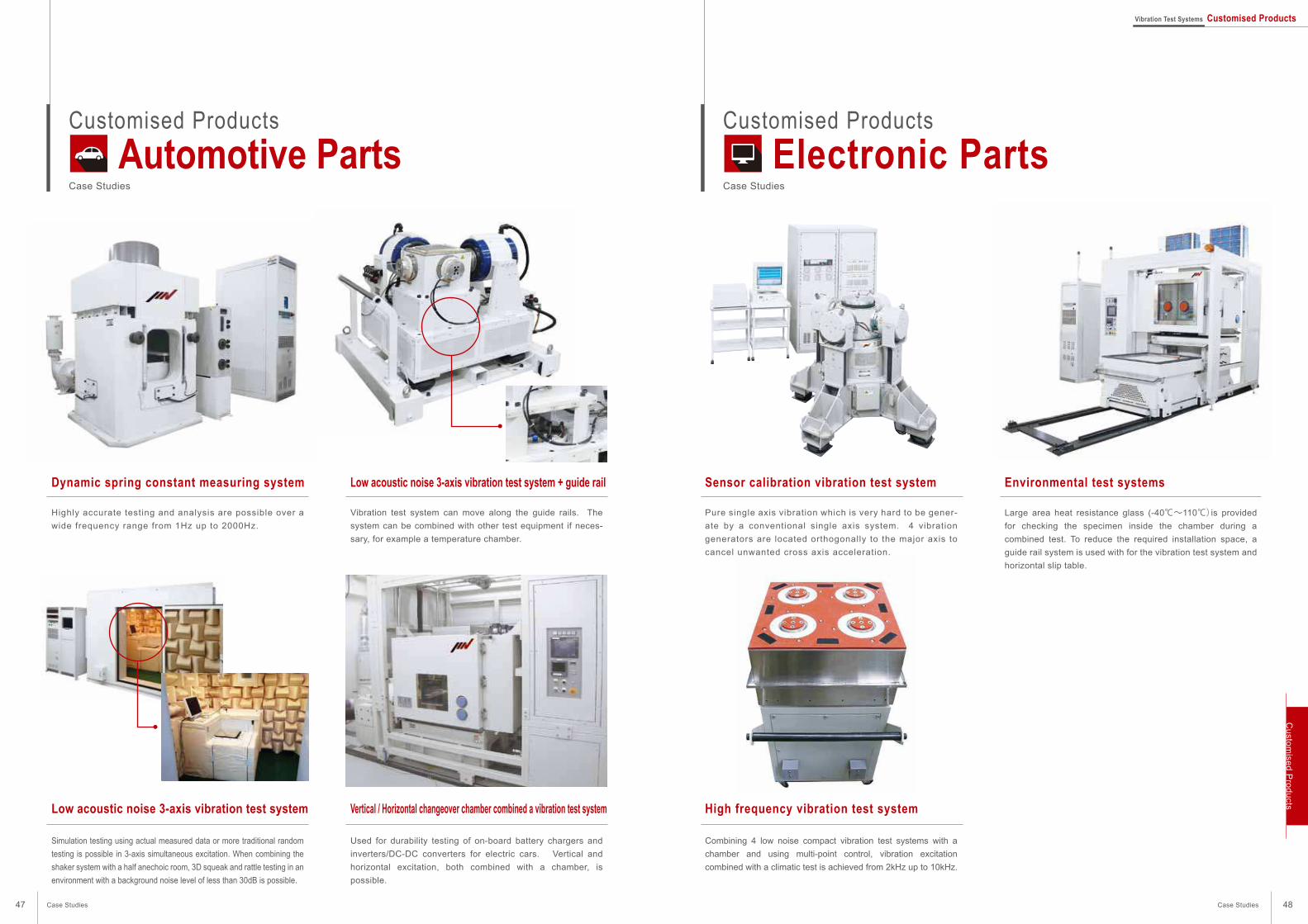
Customised Products
Electronic PartsCase Studies
Customised Products
Automotive PartsCase Studies
Sensor calibration vibration test system
Pure single axis vibration which is very hard to be gener-
ate by a conventional single axis system. 4 vibration
generators are located orthogonally to the major axis to
cancel unwanted cross axis acceleration.
Environmental test systems
Large area heat resistance glass (-40℃~110℃)is provided
for checking the specimen inside the chamber during a
combined test. To reduce the required installation space, a
guide rail system is used with for the vibration test system and
horizontal slip table.
High frequency vibration test system
Combining 4 low noise compact vibration test systems with a
chamber and using multi-point control, vibration excitation
combined with a climatic test is achieved from 2kHz up to 10kHz.
Dynamic spring constant measuring system
Highly accurate testing and analysis are possible over a
wide frequency range from 1Hz up to 2000Hz.
Low acoustic noise 3-axis vibration test system + guide rail
Vibration test system can move along the guide rails. The
system can be combined with other test equipment if neces-
sary, for example a temperature chamber.
Low acoustic noise 3-axis vibration test system
Simulation testing using actual measured data or more traditional random
testing is possible in 3-axis simultaneous excitation. When combining the
shaker system with a half anechoic room, 3D squeak and rattle testing in an
environment with a background noise level of less than 30dB is possible.
Vertical / Horizontal changeover chamber combined a vibration test system
Used for durability testing of on-board battery chargers and
inverters/DC-DC converters for electric cars. Vertical and
horizontal excitation, both combined with a chamber, is
possible.
47 48
Cu
stom
ised
Pro
du
cts
Case StudiesCase Studies
Vibration Test Systems Customised Products
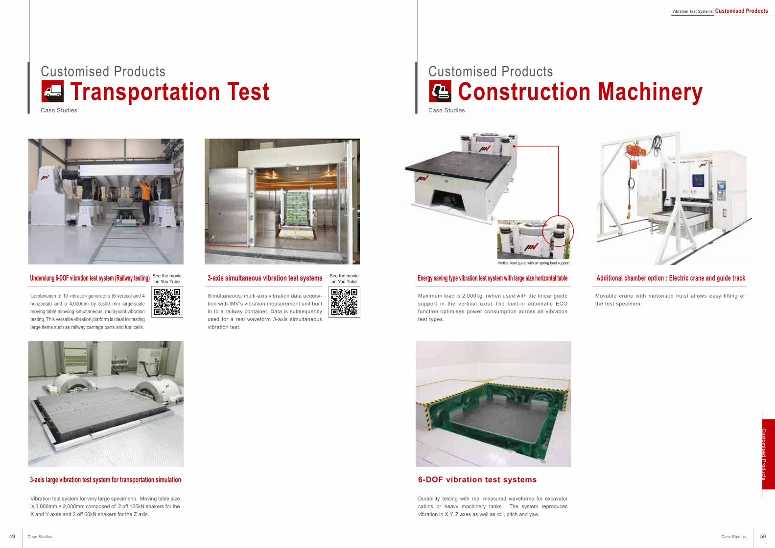
Customised Products
Construction MachineryCase Studies
Customised Products
Transportation TestCase Studies
Energy saving type vibration test system with large size horizontal table
Maximum load is 2,000kg. (when used with the linear guide
support in the vertical axis) The built-in automatic ECO
function optimises power consumption across all vibration
test types.
Additional chamber option : Electric crane and guide track
Movable crane with motorised hoist allows easy lifting of
the test specimen.
6-DOF vibration test systems
Durability testing with real measured waveforms for excavator
cabins or heavy machinery tanks. The system reproduces
vibration in X,Y, Z axes as well as roll, pitch and yaw.
Underslung 6-DOF vibration test system (Railway testing)
Combination of 10 vibration generators (6 vertical and 4
horizontal) and a 4,000mm by 3,500 mm large-scale
moving table allowing simultaneous, multi-point vibration
testing. This versatile vibration platform is ideal for testing
large items such as railway carriage parts and fuel cells.
3-axis simultaneous vibration test systems
Simultaneous, multi-axis vibration data acquisi-
tion with IMV’s vibration measurement unit built
in to a railway container. Data is subsequently
used for a real waveform 3-axis simultaneous
vibration test.
3-axis large vibration test system for transportation simulation
Vibration test system for very large specimens. Moving table size
is 3,000mm × 2,000mm composed of 2 off 125kN shakers for the
X and Y axes and 2 off 60kN shakers for the Z axis.
Vertical load guide with air spring load support
See the movieon You Tube
See the movieon You Tube
49 50
Cu
stom
ised
Pro
du
cts
Case StudiesCase Studies
Vibration Test Systems Customised Products

Customised Products
Case Studies
Customised Products
Earthquake ResistanceCase Studies
Large scale earthquake resistance vibration test systems
The unique hybrid method achieves accurate
reproduction of both large displacement and
high frequency waveforms by utilising the
benefits from an electrodynamic shaker and
an AC servomotor.
Large scale earthquake resistance vibration test systems
Industry first hybrid technology low frequency
vibration test system which simulates highly
accurate waveforms including low frequency and
high frequency components simultaneously with
a electrodynamic shaker and AC servomotor.
High accuracy signal conditioner
Equipped with 10 levels of gain and cut-off filter, for each high
precision charge amplifier. Used in the aerospace industry
where high accuracy is essential.
Large 2-axis simultaneous, multi-point excitation vibration test system
Large vibration test system with a table size of 4500mm × 4500mm.
Rated displacement: 400mm peak-to-peak horizontal, 200mm peak-to-peak vertical. Maximum load of 20 ton.
Vibration test systems for clean rooms
Air inlet and air outlet for the shaker is ducted from outside of
the clean room; this maintains the quality of the clean room
environment.
Large scale 200kN vibration test systems for the aerospace industry
With low displacement requirements for the aerospace indus-
try, this system is fitted with a Team slip table using the T-Film
bearing. High over-turning moment and low cross-axis
acceleration are features of this system in both vertical and
horizontal operation.
Aerospace
See the movieon You Tube
See the movieon You Tube
51 52
Cu
stom
ised
Pro
du
cts
Case StudiesCase Studies
Vibration Test Systems Customised Products
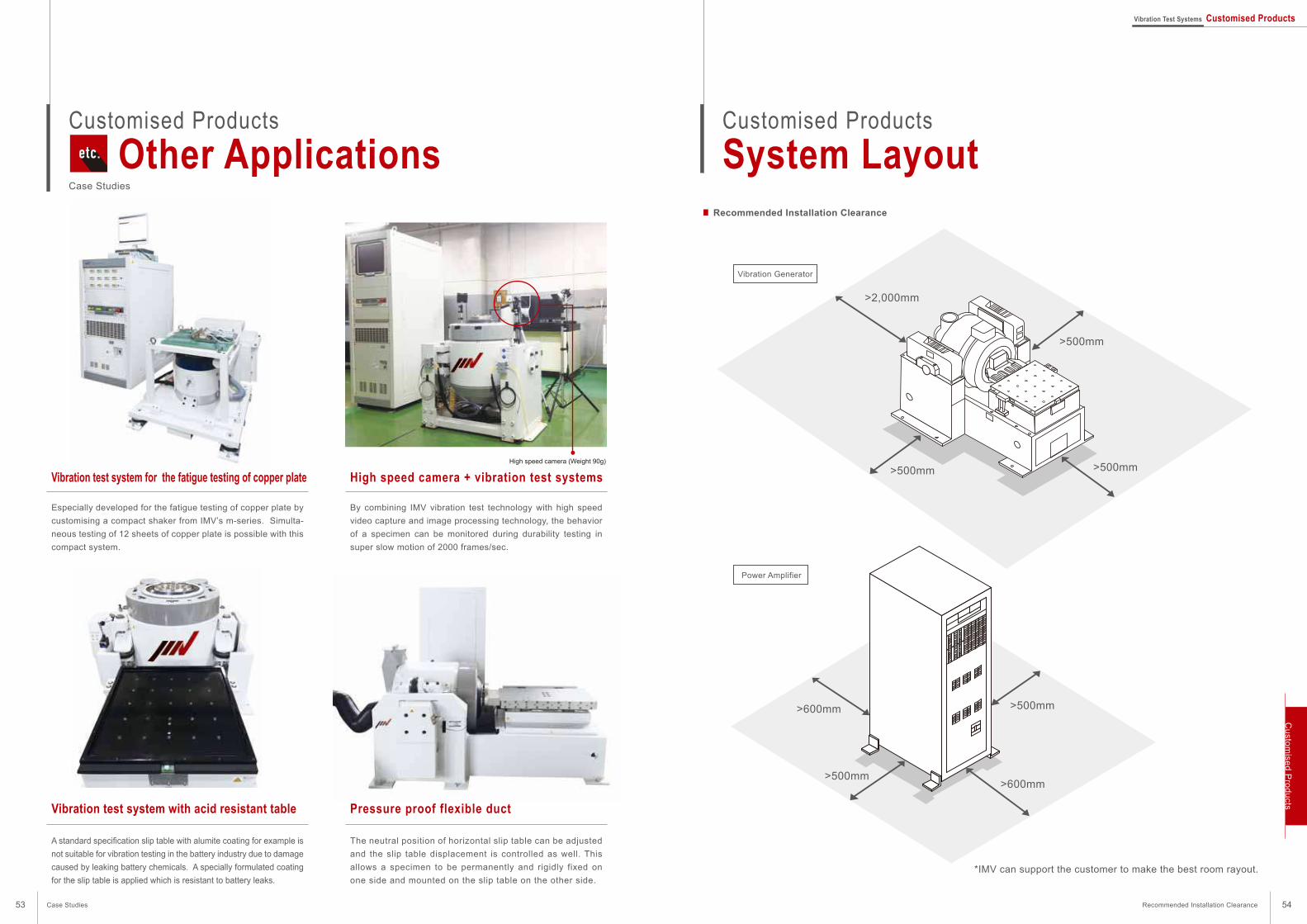
High speed camera (Weight 90g)
Customised Products
Other ApplicationsCase Studies
Vibration test system for the fatigue testing of copper plate
Especially developed for the fatigue testing of copper plate by
customising a compact shaker from IMV’s m-series. Simulta-
neous testing of 12 sheets of copper plate is possible with this
compact system.
High speed camera + vibration test systems
By combining IMV vibration test technology with high speed
video capture and image processing technology, the behavior
of a specimen can be monitored during durability testing in
super slow motion of 2000 frames/sec.
Vibration test system with acid resistant table
A standard specification slip table with alumite coating for example is
not suitable for vibration testing in the battery industry due to damage
caused by leaking battery chemicals. A specially formulated coating
for the slip table is applied which is resistant to battery leaks.
Pressure proof flexible duct
The neutral position of horizontal slip table can be adjusted
and the slip table displacement is controlled as well. This
allows a specimen to be permanently and rigidly fixed on
one side and mounted on the slip table on the other side.
Customised Products
System Layout
>500mm
>500mm>600mm
>600mm
>2,000mm
>500mm
>500mm>500mm
Vibration Generator
Power Amplifier
*IMV can support the customer to make the best room rayout.
Recommended Installation Clearance
53 54
Cu
stom
ised
Pro
du
cts
Recommended Installation ClearanceCase Studies
Vibration Test Systems Customised Products
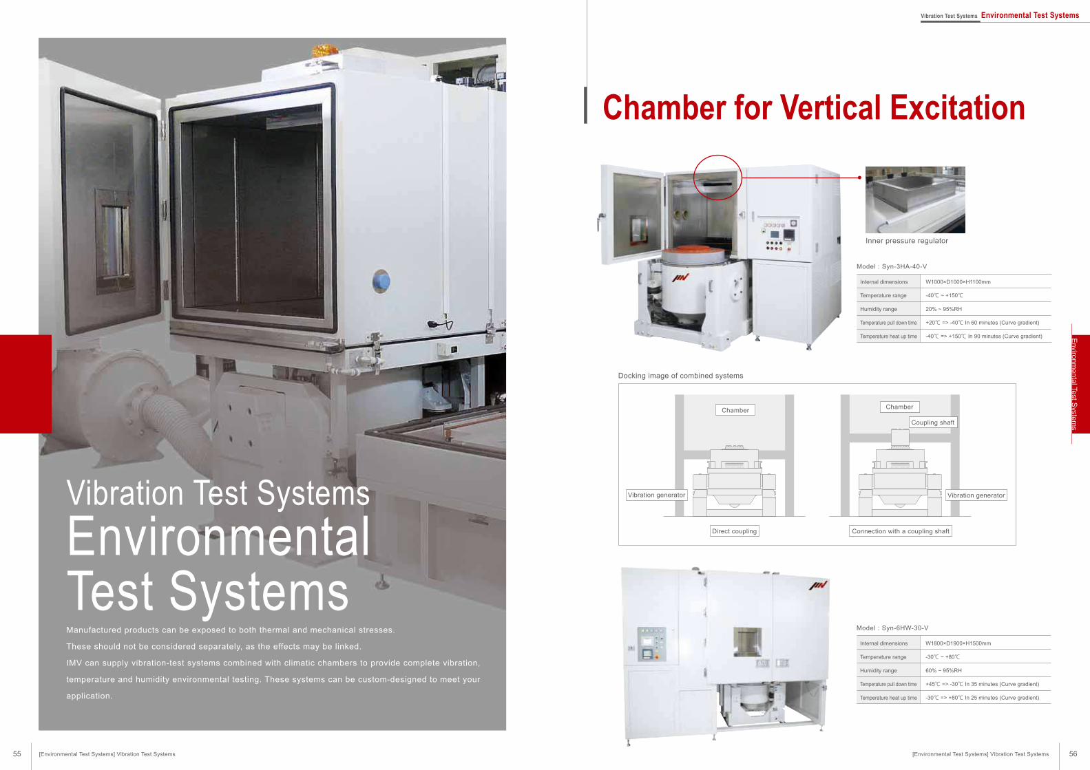
Docking image of combined systems
ChamberChamber
Coupling shaft
Vibration generator Vibration generator
Direct coupling Connection with a coupling shaft
Vibration Test Systems
EnvironmentalTest Systems
Model : Syn-6HW-30-V
W1800×D1900×H1500mm
-30℃ ~ +80℃
60% ~ 95%RH
+45℃ => -30℃ In 35 minutes (Curve gradient)
-30℃ => +80℃ In 25 minutes (Curve gradient)
Model : Syn-3HA-40-V
Internal dimensions
Temperature range
Humidity range
Temperature pull down time
Temperature heat up time
W1000×D1000×H1100mm
-40℃ ~ +150℃
20% ~ 95%RH
+20℃ => -40℃ In 60 minutes (Curve gradient)
-40℃ => +150℃ In 90 minutes (Curve gradient)
Chamber for Vertical Excitation
Manufactured products can be exposed to both thermal and mechanical stresses.
These should not be considered separately, as the effects may be linked.
IMV can supply vibration-test systems combined with climatic chambers to provide complete vibration,
temperature and humidity environmental testing. These systems can be custom-designed to meet your
application.
Inner pressure regulator
Internal dimensions
Temperature range
Humidity range
Temperature pull down time
Temperature heat up time
[Environmental Test Systems] Vibration Test Systems
Vibration Test Systems Environmental Test Systems
56
Enviro
nm
enta
l Test S
ystem
s
55 [Environmental Test Systems] Vibration Test Systems
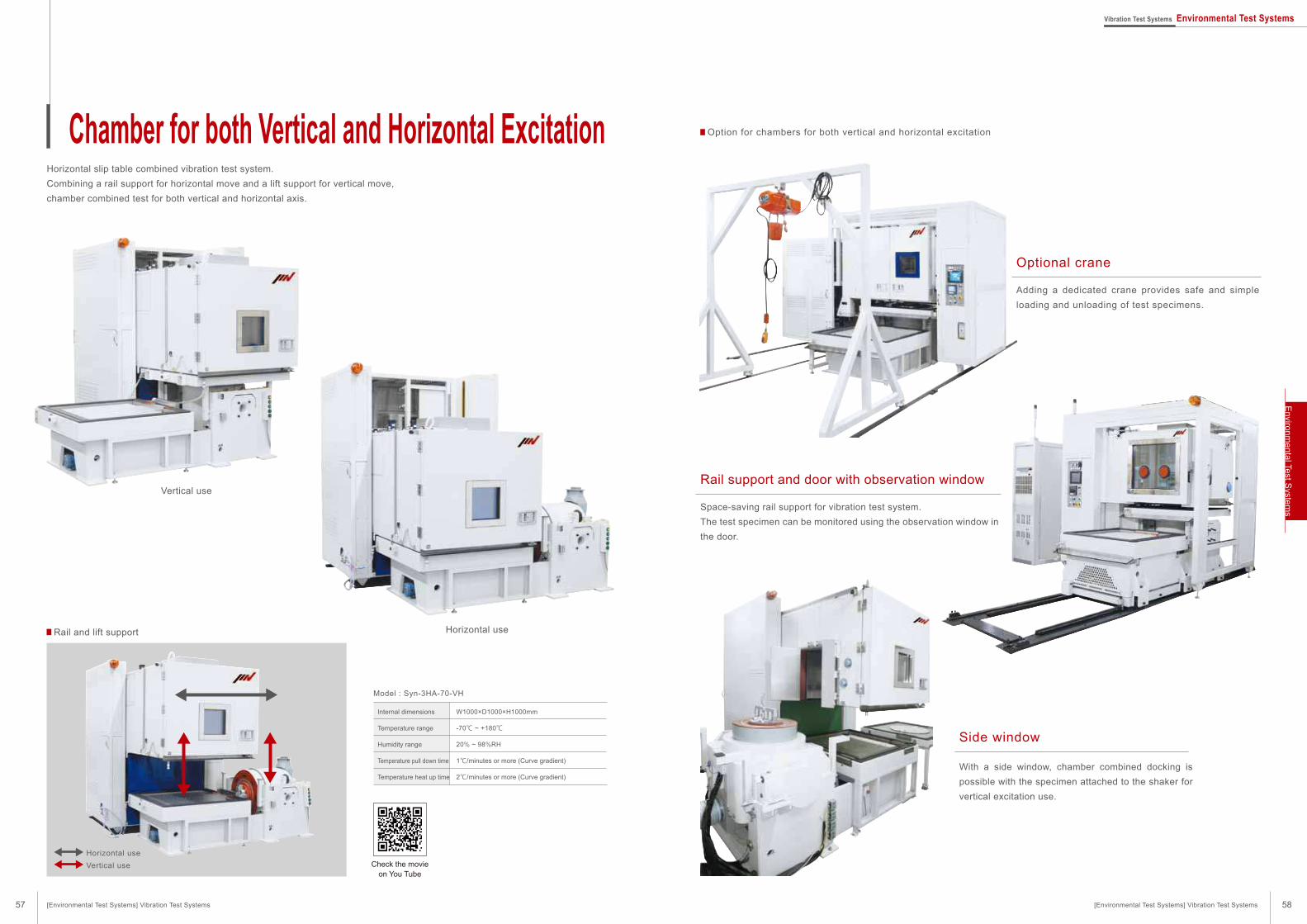
W1000×D1000×H1000mm
-70℃ ~ +180℃
20% ~ 98%RH
1℃/minutes or more (Curve gradient)
2℃/minutes or more (Curve gradient)
Vertical use
Horizontal useRail and lift support
Horizontal slip table combined vibration test system.
Combining a rail support for horizontal move and a lift support for vertical move,
chamber combined test for both vertical and horizontal axis.
Optional crane
Adding a dedicated crane provides safe and simple
loading and unloading of test specimens.
Side window
With a side window, chamber combined docking is
possible with the specimen attached to the shaker for
vertical excitation use.
Rail support and door with observation window
Space-saving rail support for vibration test system.
The test specimen can be monitored using the observation window in
the door.
Model : Syn-3HA-70-VH
Horizontal use
Vertical use
Chamber for both Vertical and Horizontal Excitation
Check the movieon You Tube
Option for chambers for both vertical and horizontal excitation
Internal dimensions
Temperature range
Humidity range
Temperature pull down time
Temperature heat up time
57 58[Environmental Test Systems] Vibration Test Systems[Environmental Test Systems] Vibration Test Systems
Vibration Test Systems Environmental Test SystemsE
nviro
nm
enta
l Test S
ystem
s
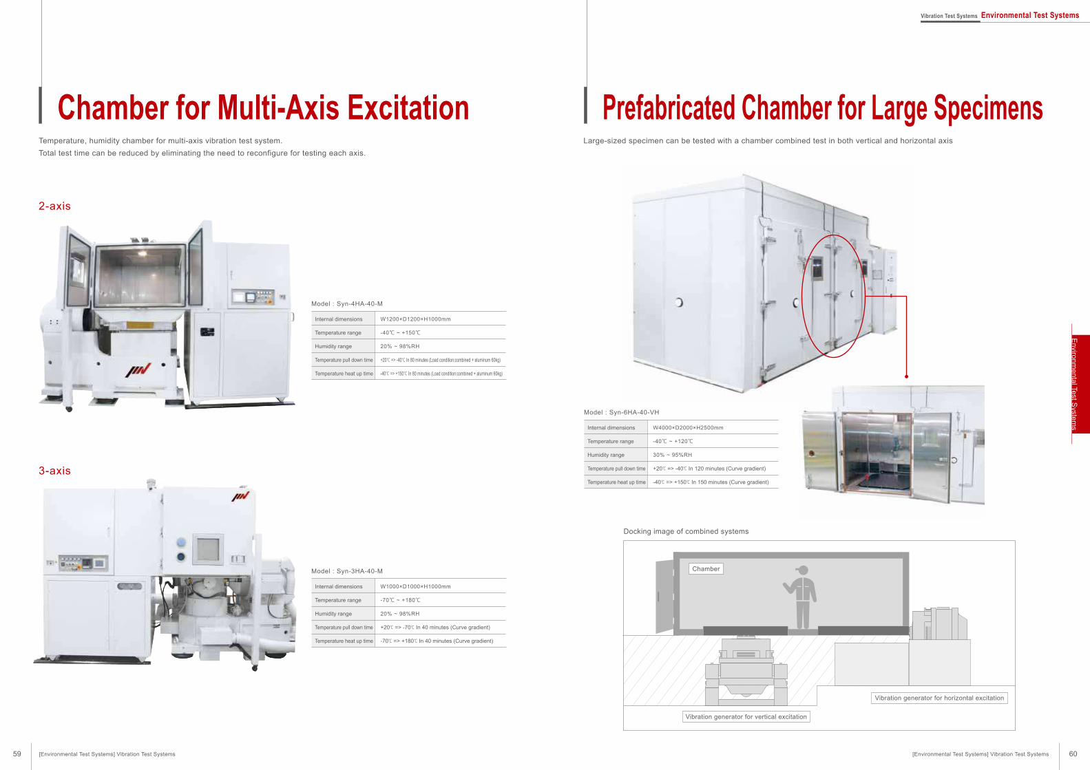
W1000×D1000×H1000mm
-70℃ ~ +180℃
20% ~ 98%RH
+20℃ => -70℃ In 40 minutes (Curve gradient)
-70℃ => +180℃ In 40 minutes (Curve gradient)
Model : Syn-3HA-40-M
W1200×D1200×H1000mm
-40℃ ~ +150℃
20% ~ 98%RH
+20℃ => -40℃ In 80 minutes (Load condition:combined + aluminum 60kg)
-40℃ => +150℃ In 80 minutes (Load condition:combined + aluminum 60kg)
Model : Syn-4HA-40-M
W4000×D2000×H2500mm
-40℃ ~ +120℃
30% ~ 95%RH
+20℃ => -40℃ In 120 minutes (Curve gradient)
-40℃ => +150℃ In 150 minutes (Curve gradient)
Model : Syn-6HA-40-VH
Temperature, humidity chamber for multi-axis vibration test system.
Total test time can be reduced by eliminating the need to reconfigure for testing each axis.
Docking image of combined systems
Large-sized specimen can be tested with a chamber combined test in both vertical and horizontal axis
2-axis
3-axis
Chamber
Vibration generator for vertical excitation
Vibration generator for horizontal excitation
Chamber for Multi-Axis Excitation Prefabricated Chamber for Large Specimens
Internal dimensions
Temperature range
Humidity range
Temperature pull down time
Temperature heat up time
Internal dimensions
Temperature range
Humidity range
Temperature pull down time
Temperature heat up time
Internal dimensions
Temperature range
Humidity range
Temperature pull down time
Temperature heat up time
59 60[Environmental Test Systems] Vibration Test Systems[Environmental Test Systems] Vibration Test Systems
Vibration Test Systems Environmental Test SystemsE
nviro
nm
enta
l Test S
ystem
s
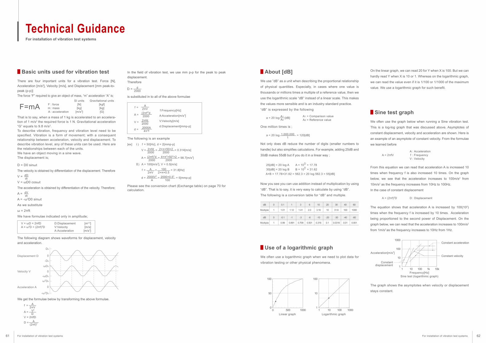
For installation of vibration test systems
Technical Guidance
In the field of vibration test, we use mm p-p for the peak to peak
displacement.
Therefore
The following is an example
[ex] ⅰ) f = 50[Hz], d = 2[mmp-p]
V = = = 0.314[m/s]
A = = = 98.7[m/s2]
Ⅱ) A = 100[m/s2], V = 0.5[m/s]
f = = = 31.8[Hz]
d = = = 5[mmp-p]
Please see the conversion chart (Exchange table) on page 70 for calculation.
There are four important units for a vibration test. Force [N],
Acceleration [m/s2], Velocity [m/s], and Displacement [mm peak-to-
peak (p-p)]
The force “F” required to give an object of mass, “m” acceleration “A” is;
We get the formulae below by transforming the above formulae.
f =
A =
V = 2πfD
D =
D = D0 sinωt
The velocity is obtained by differentiation of the displacement. Therefore
V =
V = ωD0 cosωt
The acceleration is obtained by differentiation of the velocity. Therefore;
A =
A = -ω2D0 sinωt
As we substitute
ω = 2πft
We have formulae indicated only in amplitude;
The following diagram shows waveforms for displacement, velocity
and acceleration.
Basic units used for vibration test
We use ”dB” as a unit when describing the proportional relationship
of physical quantities. Especially, in cases where one value is
thousands or millions times a multiple of a reference value, then we
use the logarithmic scale “dB” instead of a linear scale. This makes
the values more sensible and is an industry standard practice.
“dB” is expressed by the following
One million times is ;
Not only does dB reduce the number of digits (smaller numbers to
handle) but also simplifies calculations. For example, adding 25dB and
30dB makes 55dB but if you do it in a linear way ;
Now you see you can use addition instead of multiplication by using
“dB”. That is to say, it is very easy to calculate by using “dB”.
The following is a conversion table for “dB” and multiple.
About [dB]
We often use a logarithmic graph when we need to plot data for
vibration testing or other physical phenomena.
The graph shows the asymptotes when velocity or displacement
stays constant.
Use of a logarithmic graph
We often use the graph below when running a Sine vibration test.
This is a log-log graph that was discussed above. Asymptotes of
constant displacement, velocity and acceleration are shown. Here is
an example of an asymptote of constant velocity. From the formulae
we learned before
From this equation we can read that acceleration A is increased 10
times when frequency f is also increased 10 times. On the graph
below, we see that the acceleration increases to 100m/s2 from
10m/s2 as the frequency increases from 10Hz to 100Hz.
In the case of constant displacement
The equation shows that acceleration A is increased by 100(102)
times when the frequency f is increased by 10 times. Acceleration
being proportioned to the second power of Displacement. On the
graph below, we can read that the acceleration increases to 100m/s2
from 1m/s2 as the frequency increases to 10Hz from 1Hz.
On the linear graph, we can read 20 for Y when X is 100. But we can
hardly read Y when X is 10 or 1. Whereas on the logarithmic graph,
we can read the value even if it is 1/100 or 1/1000 of the maximum
value. We use a logarithmic graph for such benefit.
Sine test graph
dDdt
A2πV V2
D
A(2πf)2
d2000
A2πV
A2πV
(2πf)2d2000
(2πf)2d2000
2πfd2000
2πfd2000
2000A4π2f
2000V2
A
1002×π×0.5
4×π2×502×22000
2×π×50×22000
2000×0.52
100
dVdt
F=mA F : forcem : mass A : acceleration
SI units[N][kg]
[m/s2]
V = ωD = 2πfDA = ω2D = (2πf)2D
D:Displacement [m0-p]V:Velocity [m/s]A:Acceleration [m/s2]
Gravitational units[kgf][kg][G]
Displacement D
Velocity V
Acceleration A
D0
-D0
ωD0
-ωD0
ω2D0
-ω2D0
0
0
0
f =
A =
V =
d =
A = 2πfV
a = 20 log [dB]
a = 20 log = 120[dB]
A1 = Comparison valueA0 = Reference value
dB
Multiple
60
1000
40
100
30
31.6
20
10
10
3.16
6
2.0
3
1.41
1
1.12
0.1
1.01
0
1
f:Frequency[Hz]
A:Acceleration[m/s2]
V:Velocity[m/s]
d:Displacement[mmp-p]
A : Accelerationf : FrequencyV : Velocity
A = (2πf)2D D : Displacement
dB
Multiple
-60
0.001
-40
0.01
-30
0.0316
-20
0.1
-10
0.316
-6
0.501
-3
0.709
-1
0.891
-0.1
0.99
0
1
100
500
Linear graph Logarithmic graph
Frequency[Hz]Sine test (logarithmic graph)
Constantdisplacement
Constant velocity
Constant acceleration
Acceleration[m/s2]
1000
50
0
100
10
11 10
10
100
1000
11 1k 10k10 100
100 10000
A1
A0
25[dB] = 20 log A A = 10 = 17.78
30[dB] = 20 log B B = 10 = 31.62
A×B = 17.78×31.62 = 562.3 = 20 log 562.3 = 55[dB]
2520
3020
1,000,0001
That is to say, when a mass of 1 kg is accelerated to an accelera-
tion of 1 m/s2 the required force is 1 N. Gravitational acceleration
“G” equals to 9.8 m/s2.
To describe vibration, frequency and vibration level need to be
specified. Vibration is a form of movement; with a consequent
relationship between acceleration, velocity and displacement. To
describe vibration level, any of these units can be used. Here are
the relationships between each of the units.
We have an object moving in a sine wave.
The displacement is;
D =
is substituted in to all of the above formulae
For installation of vibration test systems For installation of vibration test systems61 62
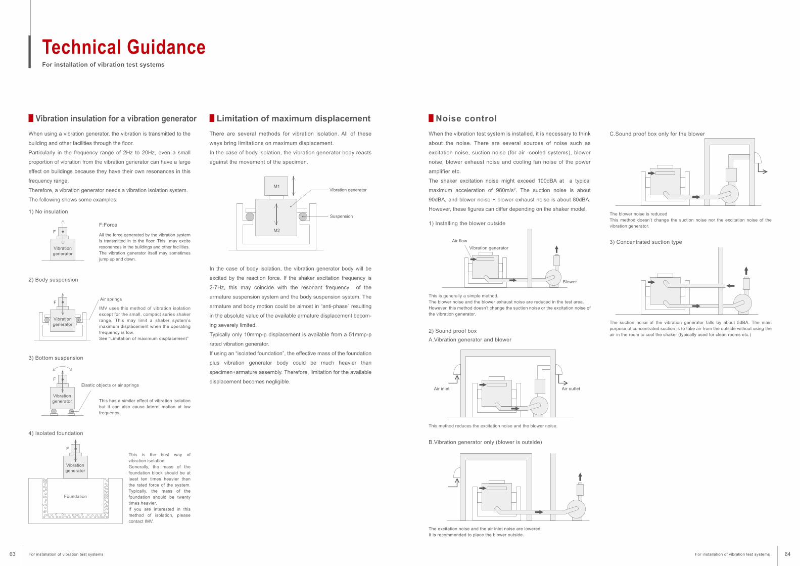
For installation of vibration test systems
Technical Guidance
There are several methods for vibration isolation. All of these
ways bring limitations on maximum displacement.
In the case of body isolation, the vibration generator body reacts
against the movement of the specimen.
In the case of body isolation, the vibration generator body will be
excited by the reaction force. If the shaker excitation frequency is
2-7Hz, this may coincide with the resonant frequency of the
armature suspension system and the body suspension system. The
armature and body motion could be almost in “anti-phase” resulting
in the absolute value of the available armature displacement becom-
ing severely limited.
Typically only 10mmp-p displacement is available from a 51mmp-p
rated vibration generator.
If using an “isolated foundation”, the effective mass of the foundation
plus vibration generator body could be much heavier than
specimen+armature assembly. Therefore, limitation for the available
displacement becomes negligible.
Limitation of maximum displacement
When using a vibration generator, the vibration is transmitted to the
building and other facilities through the floor.
Particularly in the frequency range of 2Hz to 20Hz, even a small
proportion of vibration from the vibration generator can have a large
effect on buildings because they have their own resonances in this
frequency range.
Therefore, a vibration generator needs a vibration isolation system.
The following shows some examples.
All the force generated by the vibration system
is transmitted in to the floor. This may excite
resonances in the buildings and other facilities.
The vibration generator itself may sometimes
jump up and down.
IMV uses this method of vibration isolation
except for the small, compact series shaker
range. This may limit a shaker system’s
maximum displacement when the operating
frequency is low.
See “Limitation of maximum displacement”
This has a similar effect of vibration isolation
but it can also cause lateral motion at low
frequency.
This is the best way of
vibration isolation.
Generally, the mass of the
foundation block should be at
least ten times heavier than
the rated force of the system.
Typically, the mass of the
foundation should be twenty
times heavier.
If you are interested in this
method of isolation, please
contact IMV.
Vibration insulation for a vibration generator
1) No insulation
2) Body suspension
3) Bottom suspension
4) Isolated foundation
Vibrationgenerator
Vibrationgenerator
Air springs
Elastic objects or air springs
F
When the vibration test system is installed, it is necessary to think
about the noise. There are several sources of noise such as
excitation noise, suction noise (for air -cooled systems), blower
noise, blower exhaust noise and cooling fan noise of the power
amplifier etc.
The shaker excitation noise might exceed 100dBA at a typical
maximum acceleration of 980m/s2. The suction noise is about
90dBA, and blower noise + blower exhaust noise is about 80dBA.
However, these figures can differ depending on the shaker model.
This is generally a simple method.
The blower noise and the blower exhaust noise are reduced in the test area.
However, this method doesn’t change the suction noise or the excitation noise of
the vibration generator.
Noise control
1) Installing the blower outside
This method reduces the excitation noise and the blower noise.
2) Sound proof box
A.Vibration generator and blower
The excitation noise and the air inlet noise are lowered.
It is recommended to place the blower outside.
B.Vibration generator only (blower is outside)
The blower noise is reduced
This method doesn’t change the suction noise nor the excitation noise of the
vibration generator.
C.Sound proof box only for the blower
The suction noise of the vibration generator falls by about 5dBA. The main
purpose of concentrated suction is to take air from the outside without using the
air in the room to cool the shaker (typically used for clean rooms etc.)
3) Concentrated suction type
F
Vibrationgenerator
Foundation
F
Vibrationgenerator
M1Vibration generator
Suspension
M2
F
Air flow
Vibration generator
Air inlet Air outlet
Blower
F:Force
For installation of vibration test systems For installation of vibration test systems63 64
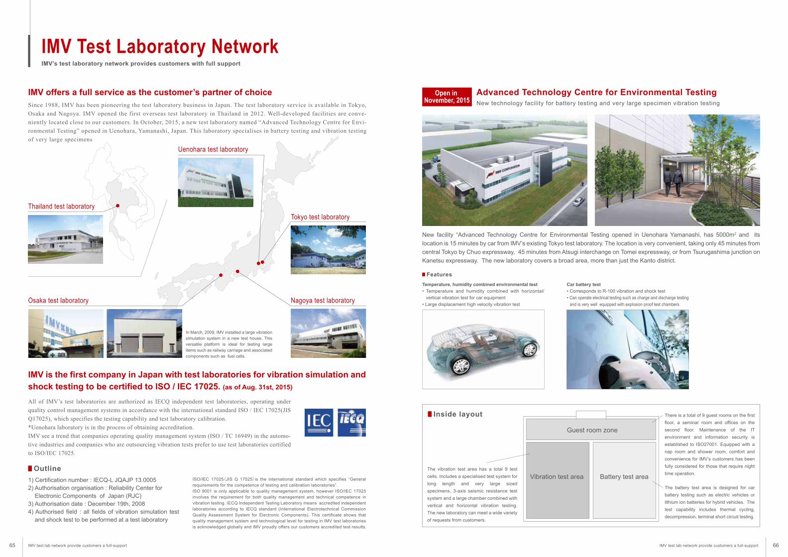
Tokyo test laboratory
Nagoya test laboratoryOsaka test laboratory
Uenohara test laboratory
IMV offers a full service as the customer’s partner of choice Advanced Technology Centre for Environmental TestingOpen in November, 2015 New technology facility for battery testing and very large specimen vibration testing
IMV’s test laboratory network provides customers with full support
IMV Test Laboratory Network
Since 1988, IMV has been pioneering the test laboratory business in Japan. The test laboratory service is available in Tokyo,
Osaka and Nagoya. IMV opened the first overseas test laboratory in Thailand in 2012. Well-developed facilities are conve-
niently located close to our customers. In October, 2015, a new test laboratory named “Advanced Technology Centre for Envi-
ronmental Testing” opened in Uenohara, Yamanashi, Japan. This laboratory specialises in battery testing and vibration testing
of very large specimens
All of IMV’s test laboratories are authorized as IECQ independent test laboratories, operating under
quality control management systems in accordance with the international standard ISO / IEC 17025(JIS
Q17025), which specifies the testing capability and test laboratory calibration.
*Uenohara laboratory is in the process of obtaining accreditation.
IMV see a trend that companies operating quality management system (ISO / TC 16949) in the automo-
tive industries and companies who are outsourcing vibration tests prefer to use test laboratories certified
to ISO/IEC 17025.
IMV is the first company in Japan with test laboratories for vibration simulation and
shock testing to be certified to ISO / IEC 17025. (as of Aug. 31st, 2015)
1) Certification number : IECQ-L JQAJP 13.00052) Authorisation organisation : Reliability Center for Electronic Components of Japan (RJC)3) Authorisation date : December 19th, 20084) Authorised field : all fields of vibration simulation test
and shock test to be performed at a test laboratory
ISO/IEC 17025(JIS Q 17025)is the international standard which specifies “General
requirements for the competence of testing and calibration laboratories”.
ISO 9001 is only applicable to quality management system, however ISO/IEC 17025
involves the requirement for both quality management and technical competence in
vibration testing. IECQ Independent Testing Laboratory means accredited independent
laboratories according to IECQ standard (International Electrotechnical Commission
Quality Assessment System for Electronic Components). This certificate shows that
quality management system and technological level for testing in IMV test laboratories
is acknowledged globally and IMV proudly offers our customers accredited test results.
In March, 2009, IMV installed a large vibration
simulation system in a new test house. This
versatile platform is ideal for testing large
items such as railway carriage and associated
components such as fuel cells.
Thailand test laboratory
New facility “Advanced Technology Centre for Environmental Testing opened in Uenohara Yamanashi, has 5000m2 and its
location is 15 minutes by car from IMV’s existing Tokyo test laboratory. The location is very convenient, taking only 45 minutes from
central Tokyo by Chuo expressway, 45 minutes from Atsugi interchange on Tomei expressway, or from Tsurugashima junction on
Kanetsu expressway. The new laboratory covers a broad area, more than just the Kanto district.
Guest room zone
Vibration test area Battery test area
Features
There is a total of 9 guest rooms on the first
floor, a seminar room and offices on the
second floor. Maintenance of the IT
environment and information security is
established to ISO27001. Equipped with a
nap room and shower room, comfort and
convenience for IMV’s customers has been
fully considered for those that require night
time operation.
The battery test area is designed for car
battery testing such as electric vehicles or
lithium ion batteries for hybrid vehicles. The
test capability includes thermal cycling,
decompression, terminal short circuit testing.
The vibration test area has a total 9 test
cells. Includes a specialised test system for
long length and very large sized
specimens, 3-axis seismic resistance test
system and a large chamber combined with
vertical and horizontal vibration testing.
The new laboratory can meet a wide variety
of requests from customers.
Outline
Inside layout
Temperature, humidity combined environmental test
• Temperature and humidity combined with horizontal/
vertical vibration test for car equipment
• Large displacement high velocity vibration test
Car battery test
• Corresponds to R-100 vibration and shock test • Can operate electrical testing such as charge and discharge testing
and is very well equipped with explosion proof test chambers
IMV test lab network provide customers a full-support IMV test lab network provide customers a full-support65 66
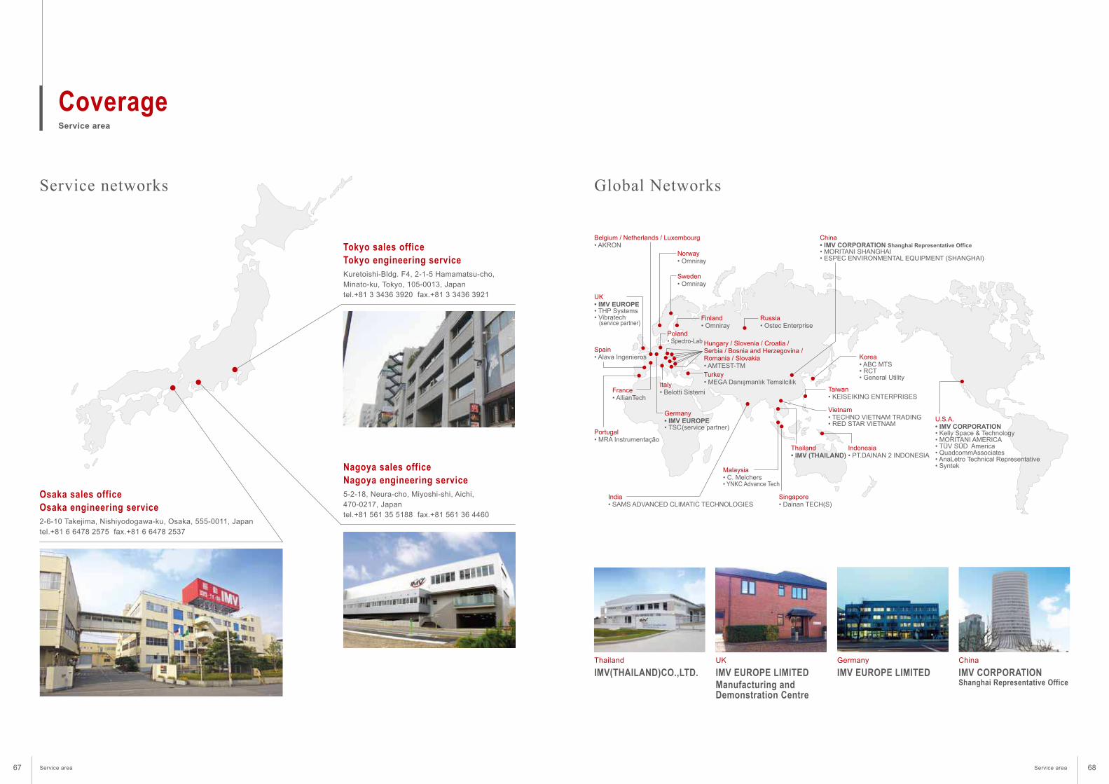
Service area
Coverage
2-6-10 Takejima, Nishiyodogawa-ku, Osaka, 555-0011, Japan
tel.+81 6 6478 2575 fax.+81 6 6478 2537
Osaka sales office
Osaka engineering service
5-2-18, Neura-cho, Miyoshi-shi, Aichi,
470-0217, Japan
tel.+81 561 35 5188 fax.+81 561 36 4460
Nagoya sales office
Nagoya engineering service
Kuretoishi-Bldg. F4, 2-1-5 Hamamatsu-cho,
Minato-ku, Tokyo, 105-0013, Japan
tel.+81 3 3436 3920 fax.+81 3 3436 3921
Tokyo sales office
Tokyo engineering service
IMV(THAILAND)CO.,LTD.
Service networks Global Networks
Thailand
IMV EUROPE LIMITED
Manufacturing and Demonstration Centre
UK
IMV EUROPE LIMITED
Germany
IMV CORPORATIONShanghai Representative Office
China
UK• IMV EUROPE• THP Systems• Vibratech (service partner)
Germany• IMV EUROPE • TSC (service partner)
U.S.A.• IMV CORPORATION• Kelly Space & Technology• MORITANI AMERICA• TÜV SÜD America• QuadcommAssociates• AnaLetro Technical Representative • Syntek
China• IMV CORPORATION Shanghai Representative Office• MORITANI SHANGHAI • ESPEC ENVIRONMENTAL EQUIPMENT (SHANGHAI)
Thailand• IMV (THAILAND)
Norway• Omniray
Belgium / Netherlands / Luxembourg• AKRON
Spain• Alava Ingenieros
Portugal• MRA Instrumentação
France• AllianTech
Italy• Belotti Sistemi
Turkey• MEGA Danışmanlık Temsilcilik
Sweden• Omniray
Finland• Omniray
Poland• Spectro-Lab
India• SAMS ADVANCED CLIMATIC TECHNOLOGIES
Malaysia• C. Melchers• YNKC Advance Tech
Vietnam• TECHNO VIETNAM TRADING• RED STAR VIETNAM
Indonesia• PT.DAINAN 2 INDONESIA
Singapore• Dainan TECH(S)
Taiwan• KEISEIKING ENTERPRISES
Russia• Ostec Enterprise
Korea• ABC MTS• RCT• General Utility
Hungary / Slovenia / Croatia /Serbia / Bosnia and Herzegovina /Romania / Slovakia• AMTEST-TM
Service area Service area67 68
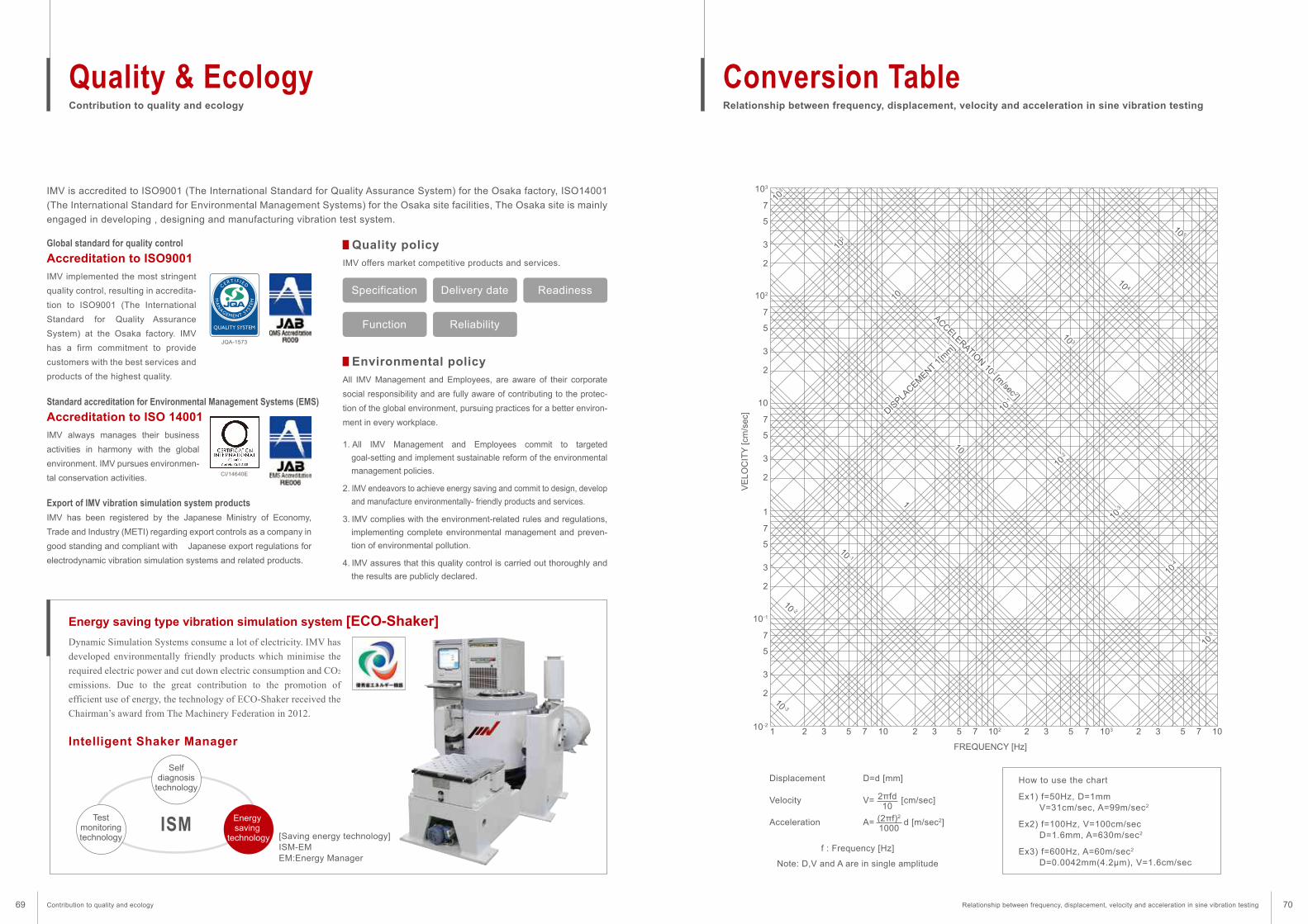
Global standard for quality control
Contribution to quality and ecology
Quality & EcologyRelationship between frequency, displacement, velocity and acceleration in sine vibration testing
Conversion Table
IMV is accredited to ISO9001 (The International Standard for Quality Assurance System) for the Osaka factory, ISO14001
(The International Standard for Environmental Management Systems) for the Osaka site facilities, The Osaka site is mainly
engaged in developing , designing and manufacturing vibration test system.
Dynamic Simulation Systems consume a lot of electricity. IMV has
developed environmentally friendly products which minimise the
required electric power and cut down electric consumption and CO2
emissions. Due to the great contribution to the promotion of
efficient use of energy, the technology of ECO-Shaker received the
Chairman’s award from The Machinery Federation in 2012.
IMV offers market competitive products and services.Accreditation to ISO9001
Standard accreditation for Environmental Management Systems (EMS)
Intelligent Shaker Manager
ISM
IMV always manages their business
activities in harmony with the global
environment. IMV pursues environmen-
tal conservation activities.
Export of IMV vibration simulation system products
IMV has been registered by the Japanese Ministry of Economy,
Trade and Industry (METI) regarding export controls as a company in
good standing and compliant with Japanese export regulations for
electrodynamic vibration simulation systems and related products.
Accreditation to ISO 14001
Energy saving type vibration simulation system [ECO-Shaker]
Quality policy
All IMV Management and Employees, are aware of their corporate
social responsibility and are fully aware of contributing to the protec-
tion of the global environment, pursuing practices for a better environ-
ment in every workplace.
1. All IMV Management and Employees commit to targeted
goal-setting and implement sustainable reform of the environmental
management policies.
2. IMV endeavors to achieve energy saving and commit to design, develop
and manufacture environmentally- friendly products and services.
3. IMV complies with the environment-related rules and regulations,
implementing complete environmental management and preven-
tion of environmental pollution.
4. IMV assures that this quality control is carried out thoroughly and
the results are publicly declared.
Environmental policy
CI/14640E
[Saving energy technology]ISM-EMEM:Energy Manager
JQA-1573
Specification
Selfdiagnosis
technology
Delivery date
Function Reliability
Readiness
Testmonitoringtechnology
Energy saving
technology
Displacement
Velocity
Acceleration
103
7
5
3
2
102
7
5
3
2
10
7
5
3
2
1
1 2 3 5 7 10 2 3 5 7 102 2 3 5 7 103 2 3 5 7 10
7
5
3
2
10-1
10-2
10 -2
10 -3
10 -1
10-1
10
102
103
10-2
10-3
10-4
10-5
1
10
10 3
DISPLA
CEMENT 1
[mm
]
10 4
10 5
7
5
3
2
f : Frequency [Hz]
Note: D,V and A are in single amplitude
FREQUENCY [Hz]V
ELO
CIT
Y [cm
/sec]
How to use the chart
Ex1) f=50Hz, D=1mmV=31cm/sec, A=99m/sec2
Ex2) f=100Hz, V=100cm/secD=1.6mm, A=630m/sec2
Ex3) f=600Hz, A=60m/sec2
D=0.0042mm(4.2µm), V=1.6cm/sec
D=d [mm]
V= [cm/sec]
A= d [m/sec2]
2πfd10
(2πf)2
1000
ACCELERATION 10 2 [m
/sec 2]
IMV implemented the most stringent
quality control, resulting in accredita-
tion to ISO9001 (The International
Standard for Quality Assurance
System) at the Osaka factory. IMV
has a firm commitment to provide
customers with the best services and
products of the highest quality.
Contribution to quality and ecology Relationship between frequency, displacement, velocity and acceleration in sine vibration testing69 70
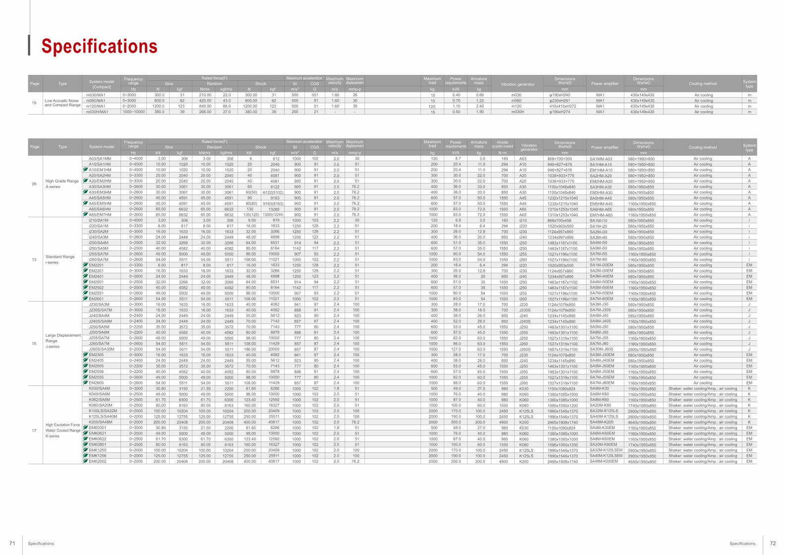
Specifications
Low Acoustic Noise and Compact Range
0~3000
0~3000
0~2000
1000~10000
300.0
600.0
1200.0
380.0
210.00
420.00
840.00
266.00
500
500
500
200
1.60
1.60
1.60
-
26
30
30
-
15
15
120
15
0.40
0.70
1.10
0.50
0.60
1.20
2.40
1.90
m030
m060
m120
m030H
300.00
600.00
1200.00
380.00
31
62
123
39
22.0
43.0
86.0
27.0
31
62
123
39
551
51
51
21
φ190xH240
φ230xH281
410x410xH372
φ190xH274
430x149x430
430x149x430
430x149x430
430x149x430
MA1
MA1
MA1
MA1
m
m
m
m
Air cooling
Air cooling
Air cooling
Air cooling
19
Page Type
m030/MA1
m060/MA1
m120/MA1
m030H/MA1
System model[Compact]
DimensionsWxHxD
DimensionsWxHxD System
typeVibration generator Power amplifier Cooling methodFrequency
range Sine
Hz
Maximumvelocity
m/s
Maximumdisplacement
mmp-p
Powerrequirements
kVA
Maximumload
kg
Armaturemass
kg
DimensionsWxHxD
DimensionsWxHxD System
typeVibrationgenerator Power amplifier Cooling method
Powerrequirements
kVA
Maximumload
kg
Armaturemass
kg
Allowableeccentric moment
N・m
N kgf
Shock
N kgf
Random
Rated force(F)
Nrms kgfrms
SI CGS
Maximum acceleration
m/s2 G
Page Type System modelFrequency
range Sine
Hz
Maximumvelocity
m/s
Maximumdisplacement
mmp-pkN kgf
Shock
kN kgf
Random
Rated force(F)
kNrms kgfrms
SI CGS
Maximum acceleration
m/s2 G
8.7
20.4
20.4
30.0
30.0
36.0
36.0
57.0
57.0
83.0
83.0
6.8
16.4
26.0
36.0
51.0
57.0
80.0
83.0
16.4
26.0
36.0
51.0
57.0
80.0
83.0
28.0
38.0
38.0
52.0
53.0
57.0
82.0
86.0
127.0
28.0
38.0
53.0
57.0
82.0
86.0
49.0
76.0
87.0
100.0
170.0
190.0
300.0
49.0
76.0
87.0
100.0
170.0
190.0
300.0
120
200
200
300
300
400
400
600
600
1000
1000
120
200
300
400
600
600
1000
1000
200
300
400
600
600
1000
1000
300
300
400
400
600
600
1000
1000
1000
300
400
600
600
1000
1000
500
1000
1000
1000
2000
2000
2000
500
1000
1000
1000
2000
2000
2000
3.0
11.0
11.0
22.0
22.0
33.0
33.0
50.0
50.0
72.0
72.0
3.0
6.4
12.8
20.0
35.0
35.0
54.0
54.0
6.4
12.8
20
35
35
54
54
17.0
18.0
26.0
28.0
45.0
45.0
63.0
63.0
63.0
17.0
26.0
45.0
45.0
63.0
63.0
27.0
40.0
40.0
60.0
100.0
100.0
200.0
27.0
40.0
40.0
60.0
100.0
100.0
200.0
160
294
294
700
700
850
850
1550
1550
1550
1550
160
294
700
850
1550
1550
1550
1550
294
700
850
1550
1550
1550
1550
700
700
850
850
1550
1550
1550
1550
1550
700
850
1550
1550
1550
1550
980
980
980
1550
2450
2450
4900
980
980
980
1550
2450
2450
4900
A03
A10
A10
A20
A20
A30
A30
A45
A45
A65
A65
i210
i220
i230
i240
i250
i250
i255
i260
i220
i230
i240
i250
i250
i255
i260
J230
J230S
J240
J240S
J250
J250
J255
J260
J260S
J230
J240
J250
J250
J255
J260
K030
K060
K060
K080
K125LS
K125LS
K200
K030
K060
K060
K080
K125LS
K125LS
K200
868×700×500
946×827×676
946×827×676
1038×933×775
1038×933×775
1100x1048x840
1100x1048x840
1232x1215x1040
1232x1215x1040
1310x1253x1040
1310x1253x1040
868x700x458
1020x903x550
1124x957x860
1234x997x890
1463x1187x1100
1463x1187x1100
1527x1196x1100
1527x1196x1100
1020x903x550
1124x957x860
1234x997x890
1463x1187x1100
1463x1187x1100
1527x1196x1100
1527x1196x1100
1124x1079x850
1124x1079x850
1234x1145x890
1234x1145x890
1463x1301x1100
1463x1301x1100
1527x1319x1100
1527x1319x1100
1657x1319x1100
1124x1079x850
1234x1145x890
1463x1301x1100
1463x1301x1100
1527x1319x1100
1527x1319x1100
1100x1090x824
1380x1085x1000
1380x1085x1000
1595x1050x1200
1990x1546x1370
1990x1546x1370
2465x1908x1740
1100x1090x824
1380x1085x1000
1380x1085x1000
1595x1050x1200
1990x1546x1370
1990x1546x1370
2465x1908x1740
580×1950×850
580×1950×850
580×1950×850
580×1950×850
580×1950×850
580x1950x850
580x1950x850
580x1950x850
1160x1950x850
580x1950x850
1160x1950x850
580x1950x850
580x1950x850
580x1950x850
580x1950x850
580x1950x850
580x1950x850
1160x1950x850
1160x1950x850
580x1950x850
580x1950x850
580x1950x850
1160x1950x850
1160x1950x850
1160x1950x850
1160x1950x850
580x1950x850
580x1950x850
580x1950x850
1160x1950x850
580x1950x850
580x1950x850
1160x1950x850
1160x1950x850
2900x1950x850
580x1950x850
580x1950x850
1160x1950x850
1160x1950x850
1160x1950x850
1160x1950x850
1160x1950x850
1160x1950x850
1160x1950x850
1740x1950x850
2900x1950x850
2900x1950x850
4640x1950x850
1160x1950x850
1160x1950x850
1160x1950x850
1740x1950x850
2900x1950x850
2900x1950x850
4640x1950x850
SA1MM-A03
SA1HM-A10
EM1HM-A10
SA2HM-A20
EM2HM-A20
SA3HM-A30
EM3HM-A30
SA5HM-A45
EM5HM-A45
SA6HM-A65
EM7HM-A65
SA1M-i10
SA1M-i20
SA2M-i30
SA3M-i40SA4M-i50
SA5M-i50
SA7M-i55
SA7M-i60
SA1M-i20EM
SA2M-i30EM
SA3M-i40EM
SA4M-i50EM
SA5M-i50EM
SA7M-i55EM
SA7M-i60EM
SA3M-J30
SA7M-J30S
SA4M-J40
SA9M-J40S
SA5M-J50
SA6M-J50
SA7M-J55
SA7M-J60
SA30M-J60S
SA3M-J30EM
SA4M-J40EM
SA5M-J50EM
SA6M-J50EM
SA7M-J55EM
SA7M-J60EM
SA4M-K30
SA6M-K60
SA8M-K60
SA20M-K80
SA32M-K125LS
SA40M-K125LS
SA48M-K200
SA4M-K30EM
SA6M-K60EM
SA8M-K60EM
SA20M-K80EM
SA32M-K125LSEM
SA40M-K125LSEM
SA48M-K200EM
A
A
A
A
A
A
A
A
A
A
A
i
i
i
i
i
i
i
i
EM
EM
EM
EM
EM
EM
EM
J
J
J
J
J
J
J
J
J
EM
EM
EM
EM
EM
EM
K
K
K
K
K
K
K
EM
EM
EM
EM
EM
EM
EM
Air cooling
Air cooling
Air cooling
Air cooling
Air cooling
Air cooling
Air cooling
Air cooling
Air cooling
Air cooling
Air cooling
Air cooling
Air cooling
Air cooling
Air cooling
Air cooling
Air cooling
Air cooling
Air cooling
Air cooling
Air cooling
Air cooling
Air cooling
Air cooling
Air cooling
Air cooling
Air cooling
Air cooling
Air cooling
Air cooling
Air cooling
Air cooling
Air cooling
Air cooling
Air cooling
Air cooling
Air cooling
Air cooling
Air cooling
Air cooling
Air cooling
Shaker: water cooling/Amp.: air cooling
Shaker: water cooling/Amp.: air cooling
Shaker: water cooling/Amp.: air cooling
Shaker: water cooling/Amp.: air cooling
Shaker: water cooling/Amp.: air cooling
Shaker: water cooling/Amp.: air cooling
Shaker: water cooling/Amp.: air cooling
Shaker: water cooling/Amp.: air cooling
Shaker: water cooling/Amp.: air cooling
Shaker: water cooling/Amp.: air cooling
Shaker: water cooling/Amp.: air cooling
Shaker: water cooling/Amp.: air cooling
Shaker: water cooling/Amp.: air cooling
Shaker: water cooling/Amp.: air cooling
High Grade Range
A-series
Standard Range
i-series
Large Displacement
Range
J-series
High Excitation Force
Water Cooled Range
K-series
0~4000
0~4500
0~4500
0~3300
0~3300
0~2600
0~2600
0~2600
0~2600
0~2600
0~2600
0~4000
0~3300
0~3000
0~2600
0~2500
0~2500
0~2600
0~2600
0~3300
0~3000
0~2600
0~2500
0~2500
0~2600
0~2600
0~3000
0~3000
0~2400
0~2400
0~2200
0~2200
0~2600
0~2600
0~2000
0~3000
0~2400
0~2200
0~2200
0~2600
0~2600
0~3000
0~2500
0~2500
0~2500
0~2000
0~2000
0~2000
0~3000
0~2500
0~2500
0~2500
0~2000
0~2000
0~2000
3.00
10.00
10.00
20.00
20.00
30.00
30.00
45.00
45.00
65.00
65.00
3.00
8.00
16.00
24.00
32.00
40.00
49.00
54.00
8.00
16.00
24.00
32.00
40.00
49.00
54.00
16.00
16.00
24.00
24.00
35.00
40.00
49.00
54.00
54.00
16.00
24.00
35.00
40.00
49.00
54.00
30.80
49.00
61.70
80.00
100.00
125.00
200.00
30.80
49.00
61.70
80.00
100.00
125.00
200.00
3.00
10.00
10.00
20.00
20.00
30.00
30.00
45.00
45.00
65.00
65.00
3.00
8.00
16.00
24.00
32.00
40.00
49.00
54.00
8.00
16.00
24.00
32.00
40.00
49.00
54.00
16.00
16.00
24.00
24.00
35.00
40.00
49.00
54.00
54.00
16.00
24.00
35.00
40.00
49.00
54.00
21.50
49.00
61.70
80.00
100.00
125.00
200.00
21.50
49.00
61.70
80.00
100.00
125.00
200.00
1000
900
900
900
900
900
900
900
900
900
900
1000
1250
1250
1200
914
1142
907
1000
1250
1250
1200
914
1142
907
1000
941
888
923
857
777
888
777
857
857
941
923
777
888
777
857
1000
1000
1000
1000
1000
1000
1000
1000
1000
1000
1000
1000
1000
1000
2.0
2.0
2.0
2.0
2.0
2.0
2.0
2.0
2.0
2.0
2.0
2.2
2.2
2.2
2.2
2.2
2.2
2.2
2.2
2.2
2.2
2.2
2.2
2.2
2.2
2.2
2.4
2.4
2.4
2.4
2.4
2.4
2.4
2.4
2.4
2.4
2.4
2.4
2.4
2.4
2.4
1.8
2.0
2.0
2.0
2.0
2.0
2.0
1.8
2.0
2.0
2.0
2.0
2.0
2.0
30
51
51
51
51
76.2
76.2
76.2
76.2
76.2
76.2
30
51
51
51
51
51
51
51
51
51
51
51
51
51
51
100
100
100
100
100
100
100
100
100
100
100
100
100
100
100
51
51
51
51
100
100
76.2
51
51
51
51
100
100
76.2
6
20
20
40
40
60
60(50)
90
90(80)
130
130(120)
9.00
16.00
32.00
48.00
64.00
80.00
98.00
108.00
16.00
32.00
48.00
64.00
80.00
98.00
108.00
40.00
40.00
55.00
70.00
70.00
80.00
98.00
108.00
196.00
40.00
55.00
70.00
80.00
98.00
108.00
61.60
98.00
123.40
160.00
200.00
250.00
400.00
61.60
98.00
123.40
160.00
200.00
250.00
400.00
306
1020
1020
2040
2040
3061
3061
4591
4591
6632
6632
306
817
1633
2449
3266
4082
5000
5511
817
1633
2449
3266
4082
5000
5511
1633
1633
2449
2449
3572
4082
5000
5511
5511
1633
2449
3572
4082
5000
5511
3150
5000
6300
8163
10204
12755
20408
3150
5000
6300
8163
10204
12755
20408
306
1020
1020
2040
2040
3061
3061
4591
4591
6632
6632
306
817
1633
2449
3266
4082
5000
5511
817
1633
2449
3266
4082
5000
5511
1633
1633
2449
2449
3572
4082
5000
5511
5511
1633
2449
3572
4082
5000
5511
2200
5000
6300
8163
10204
12755
20408
2200
5000
6300
8163
10204
12755
20408
612
2040
2040
4081
4081
6122
6122(5102)
9183
9183(8163)
1326513265(12244)
919
1633
3266
4898
6531
8164
10000
11021
1633
3266
4898
6531
8164
10000
11021
4082
4082
5612
7142
7143
8878
10000
11429
20000
4082
5612
7143
8878
10000
11429
6286
10000
12592
16327
20409
25511
40817
6286
10000
12592
16327
20409
25511
40817
102
91
91
91
91
91
91
91
91
91
91
103
128
128
123
94
117
93
102
128
128
123
94
117
93
102
97
91
95
87
80
91
80
87
87
97
95
80
91
80
87
102
102
102
102
102
102
102
102
102
102
102
102
102
102
09
13
15
17
A03/SA1MM
A10/SA1HM
A10/EM1HM
A20/SA2HM
A20/EM2HM
A30/SA3HM
A30/EM3HM
A45/SA5HM
A45/EM5HM
A65/SA6HM
A65/EM7HM
i210/SA1M
i220/SA1M
i230/SA2M
i240/SA3M
i250/SA4M
i250/SA5M
i255/SA7M
i260/SA7M
EM2201
EM2301
EM2401
EM2501
EM2502
EM2551
EM2601
J230/SA3M
J230S/SA7M
J240/SA4M
J240S/SA9M
J250/SA5M
J250/SA6M
J255/SA7M
J260/SA7M
J260S/SA30M
EM2305
EM2405
EM2505
EM2506
EM2555
EM2605
K030/SA4M
K049/SA6M
K062/SA8M
K080/SA20M
K100LS/SA32M
K125LS/SA40M
K200/SA48M
EMK0301
EMK0621
EMK0622
EMK0801
EMK1255
EMK1256
EMK2002
mm
mm
mm
mm
Specifications Specifications71 72
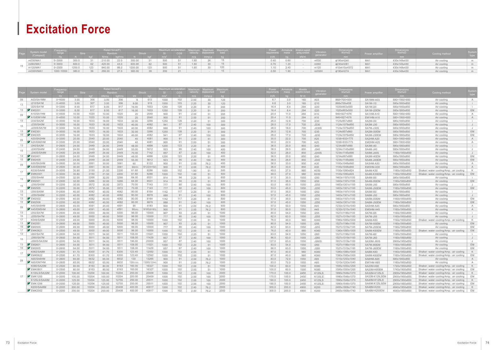
Excitation Force
m030/MA1
m060/MA1
m120/MA1
m030H/MA1
0~3000
0~3000
0~2000
1000~10000
300.0
600.0
1200.0
380.0
210.00
420.00
840.00
266.00
500
500
500
200
1.60
1.60
1.60
-
26
30
30
-
15
15
120
15
0.40
0.70
1.10
0.50
0.60
1.20
2.40
1.90
-
-
-
-
m030
m060
m120
m030H
300.00
600.00
1200.00
380.00
31
62
123
39
22.0
43.0
86.0
27.0
31
62
123
39
51
51
51
21
ɸ190xH240ɸ230xH281410x410xH372ɸ190xH274
430x149x430430x149x430430x149x430430x149x430
MA1
MA1
MA1
MA1
m
m
m
m
Air cooling
Air cooling
Air cooling
Air cooling
19
PageSystem model
[Compact]
DimensionsWxHxD
DimensionsWxHxD System
typeVibrationgenerator Power amplifier Cooling method
Frequencyrange Sine
Hz
Maximumvelocity
m/s
Maximumdisplacement
mmp-p
Powerrequirements
kVA
Maximumload
kg
Armaturemass
kg
Armature supportspring constant
kN/mN kgf
Shock
N kgf
Random
Rated force(F)
Nrms kgfrms
SI CGS
Maximum acceleration
m/s2 G
Page System modelDimensions
WxHxDDimensions
WxHxD Systemtype
Vibrationgenerator Power amplifier Cooling method
Frequencyrange Sine
Hz
Maximumvelocity
m/s
Maximumdisplacement
mmp-p
Powerrequirements
kVA
Maximumload
kg
Armaturemass
kg
Allowableeccentric moment
N・mkN kgf
Shock
kN kgf
Random
Rated force(F)
kNrms kgfrms
SI CGS
Maximum acceleration
m/s2 G
A03/SA1MM
i210/SA1M
i220/SA1M
EM2201
A10/SA1HM
A10/EM1HM
i230/SA2M
J230/SA3M
J230S/SA7M
EM2301
EM2305
A20/SA2HM
A20/EM2HM
i240/SA3M
J240/SA4M
J240S/SA9M
EM2401
EM2405
A30/SA3HM
A30/EM3HM
K030/SA4M
EMK0301
i250/SA4M
EM2501
J250/SA5M
EM2505
i250/SA5M
J250/SA6M
EM2502
EM2506
A45/SA5HM
A45/EM5HM
i255/SA7M
J255/SA7M
K049/SA6M
EM2551
EM2555
EMK0621
i260/SA7M
J260/SA7M
J260S/SA30M
EM2601
EM2605
K062/SA8M
EMK0622
A65/SA6HM
A65/EM7HM
K080/SA20M
EMK0801
K100LS/SA32M
EMK1255
K125LS/SA40M
EMK1256
K200/SA48M
EMK2002
0~4000
0~4000
0~3300
0~3300
0~4500
0~4500
0~3000
0~3000
0~3000
0~3000
0~3000
0~3300
0~3300
0~2600
0~2400
0~2400
0~2600
0~2400
0~2600
0~2600
0~3000
0~3000
0~2500
0~2500
0~2200
0~2200
0~2500
0~2200
0~2500
0~2200
0~2600
0~2600
0~2600
0~2600
0~2500
0~2600
0~2600
0~2500
0~2600
0~2600
0~2000
0~2600
0~2600
0~2500
0~2500
0~2600
0~2600
0~2500
0~2500
0~2000
0~2000
0~2000
0~2000
0~2000
0~2000
3.00
3.00
8.00
8.00
10.00
10.00
16.00
16.00
16.00
16.00
16.00
20.00
20.00
24.00
24.00
24.00
24.00
24.00
30.00
30.00
30.80
30.80
32.00
32.00
35.00
35.00
40.00
40.00
40.00
40.00
45.00
45.00
49.00
49.00
49.00
49.00
49.00
49.00
54.00
54.00
54.00
54.00
54.00
61.70
61.70
65.00
65.00
80.00
80.00
100.00
100.00
125.00
125.00
200.00
200.00
3.00
3.00
8.00
8.00
10.00
10.00
16.00
16.00
16.00
16.00
16.00
20.00
20.00
24.00
24.00
24.00
24.00
24.00
30.00
30.00
21.50
21.50
32.00
32.00
35.00
35.00
40.00
40.00
40.00
40.00
45.00
45.00
49.00
49.00
49.00
49.00
49.00
49.00
54.00
54.00
54.00
54.00
54.00
61.70
61.70
65.00
65.00
80.00
80.00
100.00
100.00
125.00
125.00
200.00
200.00
1000
1000
1250
1250
900
900
1250
941
888
1250
941
900
900
1200
923
857
1200
923
900
900
1000
1000
914
914
777
777
1142
888
1142
888
900
900
907
777
1000
907
777
1000
1000
857
857
1000
857
1000
1000
900
900
1000
1000
1000
1000
1000
1000
1000
1000
2.00
2.20
2.20
2.20
2.00
2.00
2.20
2.40
2.40
2.20
2.40
2.00
2.00
2.20
2.40
2.40
2.20
2.40
2.00
2.00
1.80
1.80
2.20
2.20
2.40
2.40
2.20
2.40
2.20
2.40
2.00
2.00
2.20
2.40
2.00
2.20
2.40
2.00
2.20
2.40
2.40
2.20
2.40
2.00
2.00
2.00
2.00
2.00
2.00
2.00
2.00
2.00
2.00
2.40
2.40
30
30
51
51
51
51
51
100
100
51
100
51
51
51
100
100
51
100
76.2
76.2
51
51
51
51
100
100
51
100
51
100
76.2
76.2
51
100
51
51
100
51
51
100
100
51
100
51
51
76.2
76.2
51
51
100
100
100
100
76.2
76.2
120
120
200
200
200
200
300
300
300
300
300
300
300
400
400400
400
400
400
400
500
500
600
600
600
600
600
600
600
600
600
600
1000
1000
1000
1000
1000
1000
1000
1000
1000
1000
1000
1000
1000
1000
1000
1000
1000
2000
2000
2000
2000
2000
2000
8.7
6.8
16.4
16.4
20.4
20.4
26.0
28.0
38.0
26.0
28.0
30.0
30.0
36.0
38.0
52.0
36.0
38.0
36.0
36.0
49.0
49.0
51.0
51.0
53.0
53.0
57.0
57.0
57.0
57.0
57.0
57.0
80.0
82.0
76.0
80.0
82.0
76.0
83.0
86.0
127.0
83.0
86.0
87.0
87.0
83.0
83.0
100.0
100.0
170.0
170.0
190.0
190.0
300.0
300.0
3.0
3.0
6.4
6.4
11.0
11.0
12.8
17.0
18.0
12.8
17.0
22.0
22.0
20.0
26.0
28.0
20.0
26.0
33.0
33.0
27.0
27.0
35.0
35.0
45.0
45.0
35.0
45.0
35.0
45.0
50.0
50.0
54.0
63.0
40.0
54.0
63.0
40.0
54.0
63.0
63.0
54.0
63.0
40.0
40.0
72.0
72.0
60.0
60.0
100.0
100.0
100.0
100.0
200.0
200.0
160
160
294
294
294
294
700
700
700
700
700
700
700
850
850
850
850
850
850
850
980
980
1550
1550
1550
1550
1550
1550
1550
1550
1550
1550
1550
1550
980
1550
1550
980
1550
1550
1550
1550
1550
980
980
1550
1550
1550
1550
2450
2450
2450
2450
4900
4900
A03
i210
i220
i220
A10
A10
i230
J230
J230S
i230
J230
A20
A20
i240
J240
J240S
i240
J240
A30
A30
K030
K030
i250
i250
J250
J250
i250
J250
i250
J250
A45
A45
i255
J255
K060
i255
J255
K060
i260
J260
J260S
i260
J260
K060
K060
A65
A65
K080
K080
K125LS
K125LS
K125LS
K125LS
K200
K200
6
9.00
16.00
16.00
20
20
32.00
40.00
40.00
32.00
40.00
40
40
48.00
55.00
70.00
48.00
55.00
60
60(50)
61.60
61.60
64.00
64.00
70.00
70.00
80.00
80.00
80.00
80.00
90
90(80)
98.00
98.00
98.00
98.00
98.00
98.00
108.00
108.00
196.00
108.00
108.00
123.40
123.40
130
130(120)
160.00
160.00
200.00
200.00
250.00
250.00
400.00
400.00
306
307
817
817
1020
1020
1633
1633
1633
1633
1633
2040
2040
2449
2449
2449
2449
2449
3061
3061
3150
3150
3266
3266
3572
3572
4082
4082
4082
4082
4591
4591
5000
5000
5000
5000
5000
5000
5511
5511
5511
5511
5511
6300
6300
6632
6632
8163
8163
10204
10204
10204
10204
10204
10204
306
306
817
817
1020
1020
1633
1633
1633
1633
1633
2040
2040
2449
2449
2449
2449
2449
3061
3061
2200
2200
3266
3266
3572
3572
4082
4082
4082
4082
4591
4591
5000
5000
5000
5000
5000
5000
5511
5511
5511
5511
5511
6300
6300
6632
6632
8163
8163
10204
10204
12755
12755
20408
20408
612
919
1633
1633
2040
2040
3266
4082
4082
3266
4082
4081
4081
4898
5612
7142
4898
5612
6122
6122(5102)
6286
6286
6531
6531
7143
7143
8164
8878
8164
8878
9183
9183(8163)
10000
10000
10000
10000
10000
10000
11021
11429
20000
11021
11429
12592
12592
13265
13265(12244)
16327
16327
20409
20409
25511
25511
40817
40817
102
103
128
128
91
91
128
97
91
128
97
91
91
123
95
87
123
95
91
91
102
102
94
94
80
80
117
91
117
91
91
91
93
80
102
93
80
102
102
87
87
102
87
102
102
91
91
102
102
102
102
102
102
102
102
868×700×500
868x700x4581020x903x5501020x903x550946×827×676
946×827×676
1124x957x8601124x1079x8501124x1079x8501124x957x8601124x1079x8501038×933×775
1038×933×775
1234x997x8901234x1145x8901234x1145x8901234x997x8901234x1145x8901100x1048x8401100x1048x8401100x1090x8241100x1090x8241463x1187x11001463x1187x11001463x1301x11001463x1301x11001463x1187x11001463x1301x11001463x1187x11001463x1301x11001232x1215x10401232x1215x10401527x1196x11001527x1319x11001380x1085x10001527x1196x11001527x1319x11001380x1085x10001527x1196x11001527x1319x11001657x1319x11001527x1196x11001527x1319x11001380x1085x10001380x1085x10001310x1253x10401310x1253x10401595x1050x12001595x1050x12001990x1546x13701990x1546x13701990x1546x13701990x1546x13702465x1908x17402465x1908x1740
580×1950×850
580x1950x850580x1950x850580x1950x850580×1950×850
580×1950×850
580x1950x850580x1950x850580x1950x850580x1950x850580x1950x850580×1950×850
580×1950×850
580x1950x850580x1950x8501160x1950x850580x1950x850580x1950x850580x1950x850580x1950x8501160x1950x8501160x1950x850580x1950x8501160x1950x850580x1950x8501160x1950x850580x1950x850580x1950x8501160x1950x8501160x1950x850580x1950x8501160x1950x8501160x1950x8501160x1950x8501160x1950x8501160x1950x8501160x1950x8501160x1950x8501160x1950x8501160x1950x8502900x1950x8501160x1950x8501160x1950x8501160x1950x8501160x1950x850580x1950x8501160x1950x8501740x1950x8501740x1950x8502900x1950x8502900x1950x8502900x1950x8502900x1950x8504640x1950x8504640x1950x850
SA1MM-A03
SA1M-i10
SA1M-i20
SA1M-i20EM
SA1HM-A10
EM1HM-A10
SA2M-i30
SA3M-J30
SA7M-J30S
SA2M-i30EM
SA3M-J30EM
SA2HM-A20
EM2HM-A20
SA3M-i40
SA4M-J40
SA9M-J40S
SA3M-i40EM
SA4M-J40EM
SA3HM-A30
EM3HM-A30
SA4M-K30
SA4M-K30EM
SA4M-i50
SA4M-i50EM
SA5M-J50
SA5M-J50EM
SA5M-i50
SA6M-J50
SA5M-i50EM
SA6M-J50EM
SA5HM-A45
EM5HM-A45
SA7M-i55
SA7M-J55
SA6M-K60
SA7M-i55EM
SA7M-J55EM
SA6M-K60EM
SA7M-i60
SA7M-J60
SA30M-J60S
SA7M-i60EM
SA7M-J60EM
SA8M-K60
SA8M-K60EM
SA6HM-A65
EM7HM-A65
SA20M-K80
SA20M-K80EM
SA32M-K125LS
SA32M-K125LSEM
SA40M-K125LS
SA40M-K125LSEM
SA48M-K200
SA48M-K200EM
A
i
i
EM
A
A
i
J
J
EM
EM
A
A
i
J
J
EM
EM
A
A
K
EM
i
EM
J
EM
i
J
EM
EM
A
A
i
J
K
EM
EM
EM
i
J
J
EM
EM
K
EM
A
A
K
EM
K
EM
K
EM
K
EM
Air cooling
Air cooling
Air cooling
Air cooling
Air cooling
Air cooling
Air cooling
Air cooling
Air cooling
Air cooling
Air cooling
Air cooling
Air cooling
Air cooling
Air cooling
Air cooling
Air cooling
Air cooling
Air cooling
Air cooling
Shaker: water cooling/Amp.: air cooling
Shaker: water cooling/Amp.: air cooling
Air cooling
Air cooling
Air cooling
Air cooling
Air cooling
Air cooling
Air cooling
Air cooling
Air cooling
Air cooling
Air cooling
Air cooling
Shaker: water cooling/Amp.: air cooling
Air cooling
Air cooling
Shaker: water cooling/Amp.: air cooling
Air cooling
Air cooling
Air cooling
Air cooling
Air cooling
Shaker: water cooling/Amp.: air cooling
Shaker: water cooling/Amp.: air cooling
Air cooling
Air cooling
Shaker: water cooling/Amp.: air cooling
Shaker: water cooling/Amp.: air cooling
Shaker: water cooling/Amp.: air cooling
Shaker: water cooling/Amp.: air cooling
Shaker: water cooling/Amp.: air cooling
Shaker: water cooling/Amp.: air cooling
Shaker: water cooling/Amp.: air cooling
Shaker: water cooling/Amp.: air cooling
09
13
13
09
13
15
13
15
09
13
15
13
15
09
17
13
15
13
15
13
15
09
13
15
17
13
15
17
13
15
13
15
17
09
17
mm
mm
mm
mm
Excitation Force Excitation Force73 74