Embed Size (px)
Citation preview

Laboratory Investigation of Concrete Beam-End TreatmentsFinal ReportMay 2015
Sponsored byFederal Highway AdministrationIowa Department of Transportation(InTrans Project 12-442)

About the BEC
The mission of the Bridge Engineering Center is to conduct research on bridge technologies to help bridge designers/owners design, build, and maintain long-lasting bridges.
Disclaimer Notice
The contents of this report reflect the views of the authors, who are responsible for the facts and the accuracy of the information presented herein. The opinions, findings and conclusions expressed in this publication are those of the authors and not necessarily those of the sponsors.
The sponsors assume no liability for the contents or use of the information contained in this document. This report does not constitute a standard, specification, or regulation.
The sponsors do not endorse products or manufacturers. Trademarks or manufacturers’ names appear in this report only because they are considered essential to the objective of the document.
Non-Discrimination Statement
Iowa State University does not discriminate on the basis of race, color, age, ethnicity, religion, national origin, pregnancy, sexual orientation, gender identity, genetic information, sex, marital status, disability, or status as a U.S. veteran. Inquiries regarding non-discrimination policies may be directed to Office of Equal Opportunity, Title IX/ADA Coordinator, and Affirmative Action Officer, 3350 Beardshear Hall, Ames, Iowa 50011, 515-294-7612, email [email protected].
Iowa Department of Transportation Statements
Federal and state laws prohibit employment and/or public accommodation discrimination on the basis of age, color, creed, disability, gender identity, national origin, pregnancy, race, religion, sex, sexual orientation or veteran’s status. If you believe you have been discriminated against, please contact the Iowa Civil Rights Commission at 800-457-4416 or Iowa Department of Transportation’s affirmative action officer. If you need accommodations because of a disability to access the Iowa Department of Transportation’s services, contact the agency’s affirmative action officer at 800-262-0003.
The preparation of this report was financed in part through funds provided by the Iowa Department of Transportation through its “Second Revised Agreement for the Management of Research Conducted by Iowa State University for the Iowa Department of Transportation” and its amendments.
The opinions, findings, and conclusions expressed in this publication are those of the authors and not necessarily those of the Iowa Department of Transportation or the U.S. Department of Transportation Federal Highway Administration.

Technical Report Documentation Page
1. Report No. 2. Government Accession No. 3. Recipient’s Catalog No.
InTrans Project 12-442
4. Title and Subtitle 5. Report Date
Laboratory Investigation of Concrete Beam-End Treatments May 2015
6. Performing Organization Code
7. Author(s) 8. Performing Organization Report No.
Travis Hosteng, Ahmad Abu-Hawash, Gordon Port, and Brent Phares InTrans Project 12-442
9. Performing Organization Name and Address 10. Work Unit No. (TRAIS)
Bridge Engineering Center
Iowa State University
2711 South Loop Drive, Suite 4700
Ames, IA 50010-8664
11. Contract or Grant No.
12. Sponsoring Organization Name and Address 13. Type of Report and Period Covered
Iowa Department of Transportation
800 Lincoln Way
Ames, IA 50010
Federal Highway Administration
U.S. Department of Transportation
1200 New Jersey Avenue SE
Washington, DC 20590
Final Report
14. Sponsoring Agency Code
SPR RB08-013
15. Supplementary Notes
Visit www.intrans.iastate.edu for color pdfs of this and other research reports.
16. Abstract
The ends of prestressed concrete beams under expansion joints are often exposed to moisture and chlorides. Left unprotected, the
moisture and chlorides come in contact with the ends of the prestressing strands and/or the mild reinforcing, resulting in
corrosion. Once deterioration begins, it progresses unless some process is employed to address it. Deterioration can lead to loss of
bearing area and therefore a reduction in bridge capacity.
Previous research has looked into the use of concrete coatings (silanes, epoxies, fiber-reinforced polymers, etc.) for protecting
prestressed concrete beam ends but found that little to no laboratory research has been done related to the performance of these
coatings in this specific type of application.
The Iowa Department of Transportation (DOT) currently specifies coating the ends of exposed prestressed concrete beams with
Sikagard 62 (a high-build, protective, solvent-free, epoxy coating) at the precast plant prior to installation on the bridge.
However, no physical testing of Sikagard 62 in this application has been completed. In addition, the Iowa DOT continues to see
deterioration in the prestressed concrete beam ends, even those treated with Sikagard 62.
The goals of this project were to evaluate the performance of the Iowa DOT-specified beam-end coating as well as other concrete
coating alternatives based on the American Association of State Highway and Transportation Officials (AASHTO) T259-80
chloride ion penetration test and to test their performance on in-service bridges throughout the duration of the project. In addition,
alternative beam-end forming details were developed and evaluated for their potential to mitigate and/or eliminate the
deterioration caused by corrosion of the prestressing strands on prestressed concrete beam ends used in bridges with expansion
joints. The alternative beam-end details consisted of individual strand blockouts, an individual blockout for a cluster of strands,
dual blockouts for two clusters of strands, and drilling out the strands after they are flush cut. The goal of all of the forming
alternatives was to offset the ends of the prestressing strands from the end face of the beam and then cover them with a
grout/concrete layer, thereby limiting or eliminating their exposure to moisture and chlorides.
17. Key Words 18. Distribution Statement
beam-end corrosion—chloride ion penetration—concrete beam ends—concrete
beam-end coatings—moisture ingress—prestressed beams
No restrictions.
19. Security Classification (of this
report)
20. Security Classification (of this
page)
21. No. of Pages 22. Price
Unclassified. Unclassified. 81 NA
Form DOT F 1700.7 (8-72) Reproduction of completed page authorized


LABORATORY INVESTIGATION OF CONCRETE
BEAM-END TREATMENTS
Final Report
May 2015
Principal Investigator
Brent M. Phares, Director
Bridge Engineering Center, Iowa State University
Co-Principal Investigator
Travis K. Hosteng, Director
National Center for Wood Transportation Structures, Iowa State University
Authors
Travis Hosteng, Ahmad Abu-Hawash, Gordon Port, and Brent Phares
Sponsored by
the Iowa Department of Transportation
and Federal Highway Administration
Preparation of this report was financed in part
through funds provided by the Iowa Department of Transportation
through its Research Management Agreement with the
Institute for Transportation
(InTrans Project 12-442)
A report from
Bridge Engineering Center
Iowa State University
2711 South Loop Drive, Suite 4700
Ames, IA 50010-8664
Phone: 515-294-8103
Fax: 515-294-0467
www.intrans.iastate.edu


v
TABLE OF CONTENTS
ACKNOWLEDGMENTS ............................................................................................................. ix
EXECUTIVE SUMMARY ........................................................................................................... xi
INTRODUCTION ...........................................................................................................................1
Problem Statement ...............................................................................................................1 Research Goal and Objectives .............................................................................................2 Research Approach ..............................................................................................................2
LITERATURE REVIEW ................................................................................................................3
LABORATORY BEAM-END COATING EVALUATION ..........................................................5
Alternative Selection ............................................................................................................5 Laboratory Ponding Tests and Results ................................................................................5
FIELD APPLICATION TO BRIDGE GIRDERS .........................................................................13
Bridge Girder Treatment ....................................................................................................13 Field Investigation Results .................................................................................................18
ALTERNATIVE BEAM-END DETAIL INVESTIGATION ......................................................52
Alternative Selection, Details, and Results ........................................................................52 Single Blockout ..................................................................................................................53
Double Blockout ................................................................................................................55 Bar Knockout (Burn Back and Patch) ...............................................................................55 Drill Out Strands ................................................................................................................57
Beam-End Grouting Investigation .....................................................................................57
CONCLUSIONS AND RECOMMENDATIONS ........................................................................65
REFERENCES ..............................................................................................................................69

vi
LIST OF FIGURES
Figure 1. Dimensions of laboratory slabs for ponding tests ............................................................6 Figure 2. Typical ponding slab with coating alternatives applied ...................................................7 Figure 3. Laboratory specimens ponded with 3% chloride solution prior to being covered ...........8
Figure 4. Chloride test results for the Andrews Slab .....................................................................10 Figure 5. Chloride test results for the Coreslab Slab .....................................................................11 Figure 6. Chloride test results for the Cretex Slab .........................................................................12
Figure 7. BD08501E – TEXCOTE XL 70 ...................................................................................15
Figure 8. BD08502 – TEXCOTE RAINSTOPPER 140 ..............................................................15 Figure 9. BD08503 – BASF Sonoguard ........................................................................................16 Figure 10. BD08504 – PAULCO TE-3008-1 ................................................................................16
Figure 11. BD08505 – Viking Aqua Guard ...................................................................................17 Figure 12. BD08506 – BASF Hydrozo 100...................................................................................17 Figure 13. BD08507 – Evercrete DPS ...........................................................................................18
Figure 14. TEXCOTE XL 70 application at plant on BD13526 .................................................19
Figure 15. TEXCOTE XL 70 field condition on BD13526 .........................................................20
Figure 16. BD08501E prior to application of TEXCOTE XL 70 ................................................20
Figure 17. TEXCOTE XL 70 applied on BD08501E ..................................................................21
Figure 18. TEXCOTE XL 70 field performance on BD08501E .................................................21
Figure 19. BC11527 prior to application of TEXCOTE XL 70 ..................................................22
Figure 20. TEXCOTE XL 70 applied on BC11527 .....................................................................22
Figure 21. TEXCOTE XL 70 field performance on BC11527 ....................................................23
Figure 22. BD13528 prior to application of TEXCOTE RAINSTOPPER 140 ...........................24
Figure 23. TEXCOTE RAINSTOPPER 140 applied to BD13528 ..............................................24
Figure 24. TEXCOTE RAINSTOPPER 140 field performance on BD13528 ............................25
Figure 25. BD08502 prior to application of TEXCOTE RAINSTOPPER 140 ...........................25
Figure 26. TEXCOTE RAINSTOPPER 140 applied to BD08502 ..............................................26
Figure 27. TEXCOTE RAINSTOPPER 140 field performance on BD08502 ............................26
Figure 28. BC11526E prior to application of TEXCOTE RAINSTOPPER 140 ........................27
Figure 29. TEXCOTE RAINSTOPPER 140 applied to BC11526E ...........................................27
Figure 30. TEXCOTE RAINSTOPPER 140 field performance on BC11526E ..........................28 Figure 31. BD13527 prior to application of Evercrete DPS ..........................................................29 Figure 32. Evercrete DPS applied to BD13527 .............................................................................29 Figure 33. Evercrete DPS field performance on BD13527 ...........................................................30 Figure 34. BD08507 prior to application of Evercrete DPS ..........................................................30
Figure 35. Evercrete DPS applied to BD08507 .............................................................................31 Figure 36. Evercrete DPS field performance on BD08507 ...........................................................31
Figure 37. BC11529 before application of Evercrete DPS ............................................................32 Figure 38. Evercrete DPS applied to BC11529 .............................................................................32 Figure 39. Evercrete DPS field performance on BC11529............................................................33 Figure 40. BD13524 before application of BASF Sonoguard .......................................................34 Figure 41. BASF Sonoguard applied to BD13524 ........................................................................34 Figure 42. BASF Sonoguard field performance on BD13524 .......................................................35 Figure 43. BD08503 before application of BASF Sonoguard .......................................................35

vii
Figure 44. BASF Sonoguard applied to BD08503 ........................................................................36 Figure 45. BASF Sonoguard field performance on BD08503 .......................................................36 Figure 46. BC11530E before application of BASF Sonoguard .....................................................37 Figure 47. BASF Sonoguard applied to BC11530E ......................................................................37
Figure 48. BASF Sonoguard field performance on BC11530E ....................................................38 Figure 49. BD13525 before application of BASF Hydrozo 100 ...................................................39 Figure 50. BASF Hydrozo 100 applied to BD13525 .....................................................................39 Figure 51. BASF Hydrozo 100 field performance on BD13525 ...................................................40 Figure 52. BD08506 before application of BASF Hydrozo 100 ...................................................40
Figure 53. BD08525 applied to BASF Hydrozo 100 .....................................................................41 Figure 54. BASF Hydrozo 100 field performance on BD08525 ...................................................41 Figure 55. BD13522E before application of Viking Aqua Guard .................................................42 Figure 56. Viking Aqua Guard applied to BD13522E ..................................................................42
Figure 57. Viking Aqua Guard field performance on BD13522E .................................................43 Figure 58. BD08505 before application of Viking Aqua Guard ...................................................43
Figure 59. Viking Aqua Guard applied to BD08505 .....................................................................44 Figure 60. Viking Aqua Guard field performance on BD08505 ...................................................44
Figure 61. BC11528 before application of Viking Aqua Guard ....................................................45 Figure 62. Viking Aqua Guard applied to BC11528 .....................................................................45 Figure 63. Viking Aqua Guard field performance on BC11528 ...................................................46
Figure 64. BD13523 before application of PAULCO TE-3008-1 .................................................47 Figure 65. PAULCO TE-3008-1 applied to BD13523 ..................................................................47
Figure 66. PAULCO TE-3008-1 field performance on BD13523 ................................................48 Figure 67. BD08504 before application of PAULCO TE-3008-1 .................................................48 Figure 68. PAULCO TE-3008-1 applied to BD08504 ..................................................................49
Figure 69. PAULCO TE-3008-1 field performance on BD08504 ................................................49
Figure 70. Beam end coated with Sikagard 62 at precast plant .....................................................50 Figure 71. Good field performance of Sikagard 62 on bridge beams ............................................51 Figure 72. Poor field performance of Sikagard 62 on bridge beams .............................................51
Figure 73. Formwork for laboratory beam-end specimens ............................................................53 Figure 74. Single Blockout formed with 1 in. foam ......................................................................54
Figure 75. Single Blockout formed with 2 in. foam ......................................................................54 Figure 76. Single Blockout formed with ¾ in. plywood with chamfered edges ...........................54
Figure 77. Double Blockout formed with 1 in. foam .....................................................................55 Figure 78. Bar knockout using pipe insulation cut to 2 in. lengths ...............................................56 Figure 79. UNIQUE Overhead and Vertical Repair ......................................................................58 Figure 80. Sikacrete 211 SCC Plus ................................................................................................59 Figure 81. Garon TIGERCRETE SP .............................................................................................59
Figure 82. UNIQUE Overhead and Vertical Repair – Batch 1 bond performance .......................60 Figure 83. UNIQUE Overhead and Vertical Repair – Batch 2 bond performance .......................61
Figure 84. UNIQUE Overhead and Vertical Repair – Batch 3 bond performance .......................62 Figure 85. UNIQUE Overhead and Vertical Repair – Batch 4 bond performance .......................63 Figure 86. Sikacrete SCC 211 Plus bond performance..................................................................64 Figure 87. Garon TIGERCRETE SP bond performance ...............................................................64

viii
LIST OF TABLES
Table 1. Coating alternatives and slab reference IDs ......................................................................7 Table 2. Ponded lab specimens chloride test results (% Cl) ............................................................9 Table 3. Bridge BD beam-end coating details ...............................................................................14
Table 4. Bridge BC beam-end coating details ...............................................................................14

ix
ACKNOWLEDGMENTS
The authors would like to thank the Iowa Department of Transportation (DOT) for sponsoring
this research with Federal Highway Administration state planning and research funding.
Special thanks are due to Ahmad Abu-Hawash, Dean Bierwagen, Wayne Sunday, and Gordon
Port of the Iowa DOT for their participation on the technical advisory committee (TAC). In
addition, the authors would like to recognize Doug Wood, manager of the Structures Laboratory
at Iowa State University (ISU), for his assistance with lab testing, Scott Schlorholtz at ISU for
his assistance with chloride testing, and undergraduate student Tyler Mahlbauer for his
assistance with specimen fabrication and monitoring.
Special thanks are due to Dennis Drews from Coreslab Structures, Jeff Butler from Cretex, and
Aaron Andrews from Andrews Prestressed Concrete for their cooperation with specimen casting
and technical assistance. Additional special thanks are due to John Kida, Danny Post, and
everyone at Unique Paving Materials. They were more than generous throughout the grout
investigation process, providing not only materials but technical advice and on-site guidance.


xi
EXECUTIVE SUMMARY
Background
The ends of prestressed concrete beams located under bridge expansion joints are often exposed
to extended periods of moisture and chlorides. This exposure can cause the beam ends to
deteriorate prematurely, corrode the prestressing strands, degrade the surrounding concrete, and
eventually reduce the capacity of the beam.
Problem Statement
Previous research has investigated the use of concrete coatings (silanes, epoxies, etc.) for
protecting prestressed concrete beam ends, but insufficient laboratory research has evaluated the
performance of these coatings for this application.
The Iowa Department of Transportation (DOT) currently specifies coating the ends of exposed
prestressed concrete beams with Sikagard 62 (a high-build, protective, solvent-free, epoxy
coating) at the precast plant prior to installation on the bridge. However, no physical testing of
Sikagard 62 for this application has been completed.
Meanwhile, the Iowa DOT continues to see deterioration even in beam ends treated with
Sikagard 62. The Iowa DOT therefore wanted to evaluate several available prestressed beam-end
treatment alternatives in the laboratory and in the field.
Research Objectives
The objectives of this research were to evaluate the performance of several concrete coating
alternatives based on the American Association of State Highway and Transportation Officials
(AASHTO) T259-80 chloride ion penetration test and to evaluate them based on their
performance on in-service bridges. In addition, alternative beam-end forming details were
developed and evaluated for their potential to mitigate the deterioration caused by corrosion of
the prestressing strands on prestressed concrete beam ends.
Key Findings
In laboratory testing, the coatings performed similarly on all three concrete slabs, indicating
that concrete mix design did not significantly affect coating performance.
For the most part, the coated slab sections resisted chloride penetration of the concrete much
better than the uncoated control sections. The only exception was the section coated with
TEXCOTE XL 70 BRIDGE COTE with Silane.
Based on the results of the AASHTO T259-80 chloride penetration test, the coatings showing
the best to worst performance were as follows: (1) three-way tie between BASF Sonoguard,
BASF Hydrozo 100, Sikagard 62 – two coats, (2) Viking Aqua Guard Concrete Sealer, (3)

xii
Sikagard 62 – one coat, (4) TEXCOTE RAINSTOPPER 140, (5) PAULCO TE-3008-1, (6)
Evercrete DPS, (7) TEXCOTE XL 70 BRIDGE COTE with Silane.
In field testing, the inspection results of the coated beam ends varied from product to product
and, at times, from one beam to another coated with the same product.
In general, the performance of all of the products was excellent. No signs of peeling or
deterioration of the coating were found on the concrete surfaces. All noticeable problems
appeared to be at the prestressing strand locations.
In the rare case when all prestressing strand ends were covered after the Iowa DOT
preparation process, the beam end showed no signs of deterioration. However, in most cases
several of the strand ends were visible and appeared rusted immediately before the coating
was applied. All visible rust was removed before applying the coatings, but this is believed to
be more a superficial fix than a long-term maintenance plan.
At the precast plant, the strands protruding from the ends of the untrimmed and untreated
beam ends were found to be heavily rusted. Before treatment, moisture and rust likely
migrated into the beam end via the strands.
The pre-existing moisture and rust on the strands within the beam ends before application of
the coating likely caused most of the failures found on the coated bridge beams. Some coated
beam ends only had visible signs of rust on the strand ends, others had visible rust piercing
the coating, and a few others had the coating peeling off and missing completely from the
strand ends.
All three grout products provided an adequate bond to the existing concrete and were easy to
mix and apply to the vertical voids. However, all three products exhibited shrinkage cracks
within a few days of application.
Implementation Readiness and Benefits
With the exception of TEXCOTE XL 70 BRIDGE COTE with Silane, the selected coating
products resisted chloride penetration of the concrete much better than the uncoated concrete.
Adding a second coat of Sikagard 62 slightly improved chloride ion penetration performance, but
likely not enough to warrant the extra time and cost involved in the process.
Single, double, or individual bar blockout are excellent options for separating the face of the
beam end and the end of the prestressing strand. Viable alternative beam-end fabrication details
include any of the blockout options: single, double, or individual strand.
Foam was found to be the best material for creating the voids. Further investigation is warranted
into potential grout products, epoxy products, or both that can adequately fill voided areas
without cracking.
Drilling out the strands after each is flush cut to the beam face was found to be nearly impossible
and is not considered a viable option.

1
INTRODUCTION
Like many other state departments of transportation (DOTs), the Iowa Department of
Transportation is facing the daunting task of maintaining an inventory of aging bridges. After
experiencing years of cost-effective construction and reduced maintenance costs, many of the
new structures built in Iowa are prestressed concrete girder bridges, and, when possible,
expansion joints are eliminated by utilizing integral abutments. However, when integral
abutments are not feasible, the Iowa DOT is faced with protecting and maintaining a concrete
superstructure with expansion joints that often expose the ends of the prestressed beams to
moisture and chlorides.
Typical prestressed concrete beam construction results in woven prestressing strands protruding
from the ends of the beams. On bridges with non-integral abutments, these strands are
subsequently cut off so as to not obstruct the construction of the bridge abutment. Beam-end
finishing details vary from state to state, some specifying that the strands be simply flush cut and
left untouched, others requiring that the beam ends be treated with epoxy or silicone sealer after
the strands are cut. Because beam ends on non-integral abutment bridges are not encased in
concrete, the final detailing of the beam ends is critical because they are fully exposed to the
elements, including potential contamination from moisture and chlorides that may penetrate the
joint. Left unprotected, these exposed strands may begin to corrode, eventually leading to cracks
and spalling of the concrete. Still, some state DOTs, including Iowa, have found that
deterioration of beam ends occurs despite their attempts to protect the beam ends with additional
detailing.
Currently, the Iowa DOT specifies prestressed concrete beam ends be coated with Sikagard 62 at
the precast plant, although there has been no laboratory investigation into the effectiveness of the
coating’s performance in this application. Individual precasters often have their own beam-end
finishing details in addition to use of the Sikagard 62, although anecdotal evidence suggest that
not all beams are actually getting the needed finishing prior to application of the coating and
installation in the field. Furthermore, as mentioned previously, the performance of in-service
bridge beams that have undergone their detailing process has been found to be highly variable
and sometimes substandard. Field inspections have found many bridge beams with exposed
strand ends that are heavily corroded and others with spalling and deterioration of the beam ends,
resulting in a potential reduction in the bearing capacity of the beam.
Problem Statement
The ends of prestressed concrete beams located under bridge expansion joints are often exposed
to extended periods of moisture and chlorides, which subsequently results in premature
deterioration of the beam ends. This results in active corrosion of the prestressing strands, which
can lead to degradation of the surrounding concrete and, eventually, loss of bearing area and a
general reduction in the capacity of the beam. There exists a need to investigate concrete beam-
end treatments and techniques for mitigating this problem on new structures and improving long-
term beam performance. Although previous research has touched on this topic, insufficient
research exists related to physically testing the treatment alternatives and evaluating their in-

2
service performance. The Iowa DOT wishes to evaluate the prestressed beam-end treatment
alternatives currently used on its prestressed girder bridges as well as other relevant options
currently available through evaluation in the laboratory and in the field.
Research Goal and Objectives
The objective of this work is to conduct laboratory testing to evaluate prestressed concrete beam-
end treatment alternatives that will prevent, or at least slow, the deterioration currently occurring
at beam ends in jointed prestressed concrete girder bridges. In addition, new beam-end
fabrication/forming details were developed and evaluated for their potential to eliminate/mitigate
the damage to beam ends that often results from moisture ingress via the exposed strand ends on
these beams. The tasks completed to meet the project objectives are as follows:
Conduct a literature review of the subject
Select several beam-end treatment alternatives, including the one currently used/specified by
the Iowa DOT (i.e., Sikagard 62)
Conduct laboratory tests to evaluate beam coating alternatives by employment of the
AASHTO T259-80 test
Apply the selected beam coating alternatives on two prestressed concrete girder bridges and
monitor for the duration of the project
Conduct laboratory tests evaluating alternative beam-end fabrication details
Research Approach
This study involved a literature review of the subject, laboratory and field evaluation of several
beam-end coating alternatives, and development and laboratory testing of several beam-end
fabrication modifications aimed at reducing strand exposure. The literature review presents
information on the state of the practice in other states, as well as other research related to the use
and performance of prestressed beam-end coatings. Laboratory testing was then completed on
several beam-end coating alternatives according to the AASHTO T259-80 test. Resistance to
chloride ion penetration is an important criterion for coatings on concrete surfaces, especially
those beam ends that are exposed on non-integral abutment bridges. Coatings that exhibit good
resistance to chloride ion penetration will be good candidates for field applications on bridge
beams in the future. All of the coating alternatives were also applied on separate full-scale
prestressed beams at the precast plant and installed in two bridges near Des Moines, Iowa, for
monitoring throughout the duration of the project. Lastly, several beam-end details were
developed and evaluated for their constructability. These details were developed with the goal of
reducing or eliminating the exposure of the prestressing strands to the elements.

3
LITERATURE REVIEW
A search of relevant literature regarding the treatments and products used to address problems
related to prestressed beam ends being exposed to the elements was conducted, the results of
which are summarized in this section. One of the more relevant and recent research projects
conducted on this subject was completed in 2012 by the Pennsylvania Department of
Transportation (PennDOT) (Radlinska et al. 2012). One of the study’s initial findings was that,
much like the Iowa DOT has found, there is a lack of available laboratory results that would
facilitate a direct comparison between the available methods and actual field applications. Based
on survey data from state DOTs, the study found that most states do nothing to protect their
concrete beam ends, nor have they conducted research on any coatings or beam-end treatments
they may utilize. The PennDOT survey also identified coatings and combination systems that
often provide the best service life and are a good low cost option based on manufacturers’ data.
The study found sealers (i.e., silane, siloxane, etc.) to be another good alternative, although these
alternatives are restricted to areas that do not have active corrosion or heavy chloride ion
concentrations. A third alternative, cathodic systems, were noted to provide the greatest
protection, but their high cost and need for continuous monitoring typically limit their use. In
addition to the DOT survey, a survey of concrete manufacturers was also completed and
indicated that the manufacturers’ suggestion for best corrosion prevention was membranes
(urethanes, epoxies, etc.) and then sealers.
The PennDOT research also found that coatings used to protect steel beams are first approved by
the National Transportation Product Evaluation Program (NTPEP) and subsequently usually
have good performance. To date, a similar approval process is not in place for concrete coatings.
Based on the survey data and information collected from various manufacturers related to ease of
application, frequency of inspection, service life, cure time, etc., the researchers concluded that
the top three available products for concrete beam-end treatment were Evercrete Deep
Penetrating Sealer (DPS), water-based asphalt emulsion, and TEXCOTE XL 70 BRIDGE
COTE.
In 2004, the Wisconsin Highway Research Program (Tabatabai et al. 2005) conducted an
extensive experimental study comparing the effectiveness of four different beam-end treatment
alternatives: (1) carbon fiber-reinforced polymer (FRP) wrap (two REPLARK 30 fabric and resin
layers, in addition to primer and putty), (2) REPLARK 30 polymer resin coating (no fiber), (3)
epoxy coating (MASTERSEAL GP epoxy sealer), and (4) sealer (MASTERSEAL SL 40 VOC).
The research involved subjecting full-scale beam ends treated with each of the alternatives to
controlled saltwater exposure and wet/dry cycles consisting of four days of “wet” exposure
followed by three “dry” days. After six months of this alternating wetting and drying, no
deterioration was evident. Therefore, corrosion was rapidly induced in the specimens by
subjecting them to cyclic wetting and drying with a 6% chloride solution along with an applied
constant voltage to the steel. The effectiveness of the coatings was subsequently evaluated based
on chloride content, extent of cracking, and observed strand corrosion. Of the four alternatives,
the FRP and polymer resin coatings were the most effective, followed by epoxy and then silane.
The researchers further concluded that the polymer resin or epoxy coatings were recommended
because the FRP was not so much more effective as to offset the additional cost of the FRP wrap.

4
Research conducted in 2002 published by the Michigan Department of Transportation (Ahlborn
et al. 2001) looked at the causes and cures for corrosion-induced deterioration in prestressed
concrete I-beam ends. The authors evaluated preventative beam-end measures based on meeting
a predetermined set of technical requirements and concluded that the procedure/product either
met requirements, did not meet requirements, or no conclusions could be drawn regarding
meeting the requirements. The research revealed that penetrating and surface sealers did not meet
the requirements, surface coatings were inconclusive, surface-applied corrosion inhibitors were
inconclusive, and impressed current cathodic protection met the requirements. Note that nowhere
in the research was cost of the alternatives considered.
Much of the research identified in the literature search that was related to concrete coating
performance was not particularly relevant to this work because the coatings were often utilized in
a repair situation or applied to concrete structures without protruding prestressing strands (e.g.,
barrier rails). One such research project, conducted by the Kentucky Transportation Center
(KTC) in 2006 (Palle and Hopwood 2006), evaluated several coating alternatives on a section of
bridge barrier rail and including subjecting each of the alternatives to several laboratory tests to
evaluate properties such as adhesion, chloride penetration, and UV degradation.

5
LABORATORY BEAM-END COATING EVALUATION
Various methodologies exist for attempting to protect concrete beam ends from the damaging
effects of moisture and chlorides. Products range from penetrating sealers, surface epoxies,
moisture blockers, etc., to more physical alternatives such as FRP wraps and strip seals. For this
work, the selection of alternatives for evaluation on laboratory and field specimens began with
selecting the current concrete coating product outlined for protecting concrete beam ends by the
Iowa DOT, Sikagard 62 (a high-build, protective, solvent-free, epoxy coating). Additional
alternatives were then selected based on results from the literature search and input from the
project’s technical advisory committee (TAC).
Alternative Selection
As noted above, the current product listed by the Iowa DOT, Sikagard 62, was an automatic
selection for evaluation for two main reasons: the Iowa DOT currently has no laboratory-based
test data for this product in this application and evaluating this product would provide a baseline
for performance evaluation in testing additional concrete coatings. As noted above, additional
alternatives were selected based on products found in previous research and then cross-
referenced with a list of currently available products meeting the application criteria. From there,
guidance and input from the TAC and Iowa DOT staff resulted in the selection of the following
alternatives for inclusion in the subsequently described experimental evaluation:
Sikagard 62 (epoxy)
TEXCOTE XL70 BRIDGE COTE with Silane
TEXCOTE RAINSTOPPER 140 (40% silane sealer)
Viking Aqua Guard Concrete Sealer (2 part – water-based epoxy)
PAULCO TE-3008-1 (2 part – solvent-based epoxy)
BASF Sonoguard (2 part – polyurethane waterproofer)
BASF Hydrozo 100 (100% silane penetrating sealer)
Evercrete Deep Penetrating Sealer (DPS)
Laboratory Ponding Tests and Results
The method for evaluating the performance of the selected concrete coating alternatives was the
AASHTO T259-80 test (Standard Method of Test for Resistance of Concrete to Chloride Ion
Penetration). Laboratory testing of the selected beam-end coating alternatives consisted of first
casting three concrete ponding slabs, one from each of the three precast facilities located in or
near Iowa: Coreslab Structures, Omaha, Nebraska; Cretex, Iowa Falls, Iowa; Andrews
Prestressed Concrete, Mason City, Iowa. (Note: Prior to completion of testing, the Andrews
facility closed for business.) The purpose of obtaining a ponding slab from each of the three
precasters was to evaluate if concrete mix design or differences in concrete placement techniques
had any effect on the performance of the coating alternatives.

6
Each slab was cast on-site at the precast plant and then transported to the Iowa State University
(ISU) structural engineering laboratory for testing. Illustrated in Figure 1 is a plan view of a
typical ponding slab; all three slabs were 5 ft by 7 ft in plane and 6 in. thick. The slab dimensions
allowed for 12 squares per slab for application of the 8 selected alternatives, several control
(untreated) areas, a ponding barrier, and lifting loops. The dotted lines in Figure 1 denote the
location of the edge of each coating alternative; the solid lines within the dams designate the
boundaries of the area from which samples were taken for testing. The buffer area between the
dotted and solid lines reduces the potential for erroneous readings due to insufficient coverage of
the concrete at the interface between two coating alternatives. To assist with the referencing of
the slabs and the applied alternatives, each row of squares on the slab was designated with a
letter from A to D, and each column was designated with a number from 1 to 3 (see Figure 1).
Figure 1. Dimensions of laboratory slabs for ponding tests
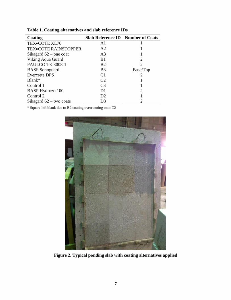
To simulate application of the coating alternatives on a vertical beam end, the ponding slabs
were stood on edge and each alternative applied to a designated square on each slab according to
manufacturer recommendations (see Table 1). Figure 2 shows one slab after application of the
coating alternatives (all but D3) and prior to ponding; the other two slabs looked very similar and
are not shown in the interest of brevity.
6" Typ.1.5" tall dams
5'
7'
9"
6"
1'
1'
A
B
C
D
1 2 3
7
Table 1. Coating alternatives and slab reference IDs
Coating Slab Reference ID Number of Coats
TEXCOTE XL70 A1 1
TEXCOTE RAINSTOPPER A2 1
Sikagard 62 – one coat A3 1
Viking Aqua Guard B1 2
PAULCO TE-3008-1 B2 2
BASF Sonoguard B3 Base/Top
Evercrete DPS C1 2
Blank* C2 1
Control 1 C3 1
BASF Hydrozo 100 D1 2
Control 2 D2 1
Sikagard 62 – two coats D3 2
* Square left blank due to B2 coating overrunning onto C2
Figure 2. Typical ponding slab with coating alternatives applied

8
The application of two coats of Sikagard 62 to D3 was at the request of Iowa DOT staff to
evaluate any potential benefit to using two coats versus the typical one-coat application specified
by the manufacturer, and both coats were applied after the photo was taken but prior to ponding.
After the coatings were applied and had been allowed sufficient time to cure, as specified by the
manufacturers, the slabs were laid horizontally and subjected to continuous ponding with a 3%
chloride solution to a depth of approximately 0.5 in. for 90 days. Each slab was outfitted with
aeration tubes to keep the chlorides from settling out of solution and then covered to reduce
evaporation; additional solution was periodically added when needed to maintain a proper depth
of chloride solution (see Figure 3).
Figure 3. Laboratory specimens ponded with 3% chloride solution prior to being covered
After 90 days of ponding, the slabs were drained, lightly brushed, and vacuumed to remove any
chloride residue prior to extracting the needed powder samples. A small area of each coating was
then removed, the area was cleaned thoroughly, and then samples were extracted at each location
at depths of 0.5 in. and 1.0 in. and taken to a materials testing laboratory at ISU for chloride
analysis. Each of the holes where the samples were taken was then filled with caulk to prevent
the creation of an alternative entry point for the chloride solution. This process of ponding,
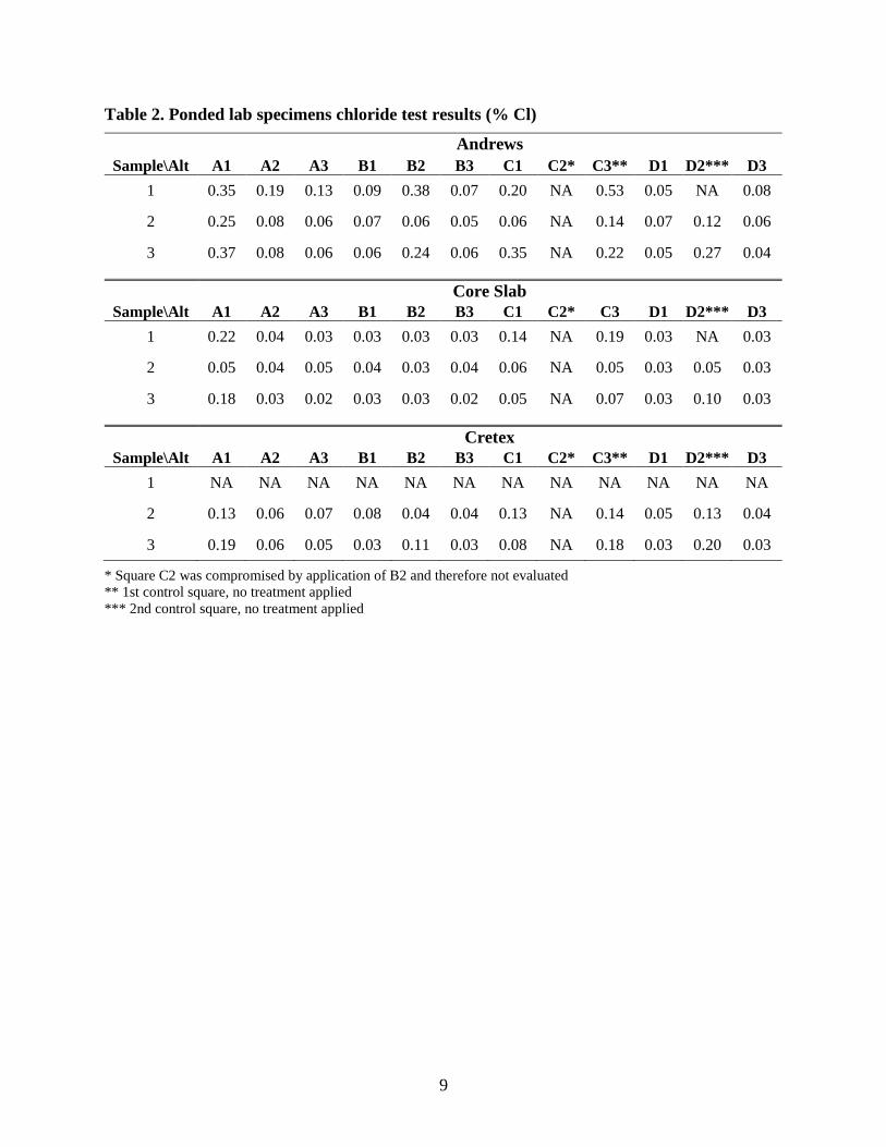
drying, sampling, and caulking was then repeated two more times. Listed in Table 2, and shown
in Figures 4 through 6, are the results from the three chloride samplings done on the three slabs.
The first round of samples from the Cretex slab were unfortunately compromised in the time
between collecting the samples and testing the samples and are therefore presented as not
applicable (NA).
9
Table 2. Ponded lab specimens chloride test results (% Cl)
Andrews
Sample\Alt A1 A2 A3 B1 B2 B3 C1 C2* C3** D1 D2*** D3
1 0.35 0.19 0.13 0.09 0.38 0.07 0.20 NA 0.53 0.05 NA 0.08
2 0.25 0.08 0.06 0.07 0.06 0.05 0.06 NA 0.14 0.07 0.12 0.06
3 0.37 0.08 0.06 0.06 0.24 0.06 0.35 NA 0.22 0.05 0.27 0.04
Core Slab
Sample\Alt A1 A2 A3 B1 B2 B3 C1 C2* C3 D1 D2*** D3
1 0.22 0.04 0.03 0.03 0.03 0.03 0.14 NA 0.19 0.03 NA 0.03
2 0.05 0.04 0.05 0.04 0.03 0.04 0.06 NA 0.05 0.03 0.05 0.03
3 0.18 0.03 0.02 0.03 0.03 0.02 0.05 NA 0.07 0.03 0.10 0.03
Cretex
Sample\Alt A1 A2 A3 B1 B2 B3 C1 C2* C3** D1 D2*** D3
1 NA NA NA NA NA NA NA NA NA NA NA NA
2 0.13 0.06 0.07 0.08 0.04 0.04 0.13 NA 0.14 0.05 0.13 0.04
3 0.19 0.06 0.05 0.03 0.11 0.03 0.08 NA 0.18 0.03 0.20 0.03
* Square C2 was compromised by application of B2 and therefore not evaluated
** 1st control square, no treatment applied
*** 2nd control square, no treatment applied

10
Figure 4. Chloride test results for the Andrews Slab
11
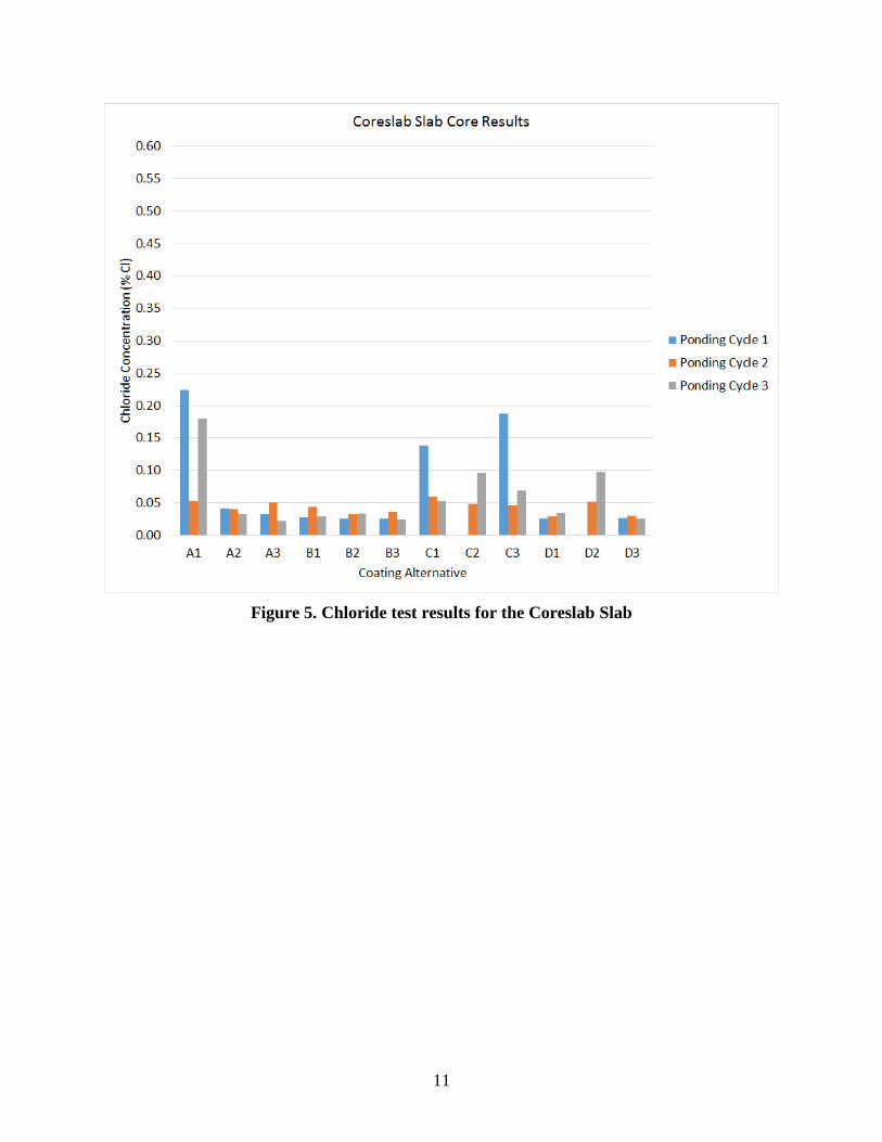
Figure 5. Chloride test results for the Coreslab Slab

12
Figure 6. Chloride test results for the Cretex Slab
Table 2 and Figures 4 through 6 provide several useful pieces of information. (Recall that
Andrews is no longer a precast supplier, so the presented data is for informational purposes
only.) First, in general, all three slabs performed relatively the same, indicating that differences
between the suppliers do not have a notable effect on the performance of the concrete coating
alternatives. Additionally, visual inspection throughout the project found there to be no issues
with adhesion of any of the alternatives to the concrete surfaces provided by all three
manufacturers throughout the three ponding cycles. Second, if we compare the performance of
the control squares (C3 and D2) with all the squares that had an applied coating, there is a
general improvement of the chloride resistance where a coating is used, as expected. The one
exception to this is the TEXCOTE XL 70 product; based on the results from the laboratory
ponding tests, this was the only alternative to not perform better than the control. Third, although
the chloride contents varied up and down slightly from one ponding cycle to the next, the
variances were relatively small and showed no notable increase in the chloride content of the
concrete over the course of the three ponding cycles. Lastly, using the numbers in Table 2 or
Figures 4 through 6 as a guide, the alternatives may be rated as follows in terms of decreasing
performance to resist chloride penetration into the concrete: (1) tie: BASF Sonoguard, BASF
Hydrozo 100, Sikagard 62 – two coats, (2) Viking Aqua Guard, (3) Sikagard 62 – one coat, (4)
TEXCOTE RAINSTOPPER 140, (5) PAULCO TE-3008-1, (6) Evercrete, (7) TEXCOTE XL
70.

13
FIELD APPLICATION TO BRIDGE GIRDERS
The initial scope of this work called for only a laboratory investigation of the selected beam-end
treatment alternatives. However, during the alternative selection process the research team was
made aware of two prestressed concrete girder bridges scheduled for fabrication/construction
during the research project timeframe. The TAC suggested including a field component to the
scope of the project by applying the selected beam-end coating alternatives to the beam ends on
these two projects and visually monitoring their performance. Subsequently, the research team
reached out to the precaster to establish a timeline of events (i.e., status of beam fabrication, etc.)
so that as soon as the beams were cast and had been properly prepared for the coating process the
research team could be on-site to apply the alternatives prior to the beams being sent out to the
construction site. Note that Sikagard 62 was not applied to these girders.
Before outlining the application of the coating alternatives to the bridge beams and discussing
their field performance in the subsequent section, the research team believes it would be remiss
to not discuss a couple of details discovered during the literature review and a site visit to the
precast plant. Results from previous research indicated that silanes should only be applied to
areas that have no active corrosion or heavy chloride ion concentrations. Initial inspection of the
19 beam ends reserved for this research found them to have been prepped according to the Iowa
DOT specifications, although there were numerous prestressing strand ends that were visible and
showing signs of rust, some significant. A cursory inspection of other beam ends in the precast
yard found many beams awaiting the precaster’s beam-end finishing process with uncut
prestressing strands protruding from the beam ends. All of those exposed strands were visibly
rusted. The potential exists that these exposed strands, which by their very nature have gaps
created when the individual strands are woven together, could draw moisture into the end of the
beam by capillary action. When these strands are eventually cut in preparation for beam-end
treatment, the exposed rusty strands are removed, but the level of corrosion and moisture that has
migrated down the strand and is encased in concrete is unknown. Any rust and moisture that
does exist within the concrete is subsequently covered up either by the beam-end treatment
process and the coating or, in the worst case, by just the coating itself. The presence of moisture
and pre-existing rust on the strand within the concrete are potentially a significant source, if not
the source, of the rust that is prematurely degrading the beam-end treatment and coatings.
Furthermore, most of the coating alternatives, including the DOT-specified Sikagard 62, are
designed to protect concrete surfaces, not steel surfaces, from moisture/chloride ingress.
Bridge Girder Treatment
The two bridges selected for inclusion in this testing are the Interstate 35 Bridge (Bridge BD)
over E.P. True Parkway in West Des Moines, Iowa, and the US 65 Overflow Bridge (Bridge BC)
on the southeast side of Des Moines, Iowa. Bridge BD had the abutment ends of all seven
prestressed girders coated at both the north and south abutments; Bridge BC had all five beam
ends coated at one abutment. Tables 3 and 4 list the beam numbers and corresponding coatings
applied to each of Bridge BD and BC’s beams, respectively.

14
Table 3. Bridge BD beam-end coating details
Bridge ID Location Beam ID Alternative Number
of Coats
BD S. Abutment BD08501E TEXCOTE XL 70 1
BD S. Abutment BD08502 TEXCOTE RAINSTOPPER 1
BD S. Abutment BD08503 BASF Sonoguard Base/Top
BD S. Abutment BD08504 PAULCO TE-3008-1 2
BD S. Abutment BD08505 Viking Aqua Gaurd 2
BD S. Abutment BD08506 BASF Hydrozo 100 2
BD S. Abutment BD08507 Evercrete DPS 2
BD N. Abutment BD13522E Viking Aqua Gaurd 2
BD N. Abutment BD13523 PAULCO TE-3008-1 2
BD N. Abutment BD13524 BASF Sonoguard Base/Top
BD N. Abutment BD13525 BASF Hydrozo 100 2
BD N. Abutment BD13526 TEXCOTE XL 70 1
BD N. Abutment BD13527 Evercrete DPS 2
BD N. Abutment BD13528E TEXCOTE RAINSTOPPER 1
Table 4. Bridge BC beam-end coating details
Bridge ID Location Beam ID Alternative Number
of Coats
BC N. Abutment BC11526E TEXCOTE RAINSTOPPER 1
BC N. Abutment BC11527 TEXCOTE XL70 1
BC N. Abutment BC11528 Viking Aqua Guard 2
BC N. Abutment BC11529 Evercrete DPS 2
BC N. Abutment BC11530E BASF Sonoguard Base/Top
Figures 7 through 13 show a representative prestressed concrete beam end after application of
each of the seven coating alternatives at the precast plant. As noted previously, all of the girders
were prepared for coating application by the precaster as per their own specifications. In
addition, immediately prior to application of the coatings, at the recommendation of the Iowa
DOT, the research team removed any visible surface rust from the prestressing strand ends using
an angle grinder and removed any dust and visible surface debris.

15
Figure 7. BD08501E – TEXCOTE XL 70
Figure 8. BD08502 – TEXCOTE RAINSTOPPER 140

16
Figure 9. BD08503 – BASF Sonoguard
Figure 10. BD08504 – PAULCO TE-3008-1

17
Figure 11. BD08505 – Viking Aqua Guard
Figure 12. BD08506 – BASF Hydrozo 100

18
Figure 13. BD08507 – Evercrete DPS
Note that approximately one month after application of the coating alternatives to the Bridge BC
beams, the precast foreman and the Iowa DOT inspector mentioned that it appeared as though a
couple of the Bridge BC beams had not had a coating applied, and others were already showing
visible signs of rusting of the prestressing strand ends. Review of the notes and photos from the
application date, as well as an on-site visit by the research team, confirmed that all the beams had
been coated with the appropriate coating alternative. Still, a couple of the beam ends were
showing signs of rust on the beam ends. This observation may be directly related to the
previously mentioned condition of the strands prior to treatment of the beam ends, and this
condition appears to be a significant factor in the performance of the coatings. During the
inspection visit by the research team, all visible rust was again removed using an angle grinder
and the appropriate coating reapplied. The beams and respective coatings that were touched up in
this way were BC11526E TEXCOTE RAINSTOPPER, BC11527 TEXCOTE XL 70 BRIDGE
COTE, and BC11529 Evercrete DPS.
Field Investigation Results
The following outlines the performance of each of the coating alternatives on the bridge girders
treated with the selected coating alternatives. The notes and photos below are from the inspection
conducted after nearly 18 months of service in the field. Photos of each beam before and/or
shortly after applying the coating accompany a photo taken at time of final inspection to clarify
the notes presented below. Although the entire ends of the beams were treated with each

19
alternative, the field inspection focused on the bottom flanges of the beams because the top
flanges were often encased in the abutment diaphragm/deck and therefore not visible.
Overall, the field performance of all the coating alternatives was generally very good on the
concrete surface of the beam end. As noted previously, many of the beam prestressing strands
exhibited signs of rusting prior to application of the coatings, and the potential exists that given
the beam-end preparation procedure some level of rusting/moisture exists on/within the woven
strands within the concrete. That said, most of the issues identified with the coating alternatives,
even with Sikagard 62, were found at the locations of the prestressing strand ends. Pre-existing
rust/moisture on the strands could be the influential factor at play in these failures, although other
unknown factors may also be contributing.
TEXCOTE XL 70 BRIDGE COTE with Silane
This product showed similar levels of performance on the three prestressed beams to which it
was applied (see Figures 14 through 21).
Figure 14. TEXCOTE XL 70 application at plant on BD13526

20
Figure 15. TEXCOTE XL 70 field condition on BD13526
Figure 16. BD08501E prior to application of TEXCOTE XL 70

21
Figure 17. TEXCOTE XL 70 applied on BD08501E
Figure 18. TEXCOTE XL 70 field performance on BD08501E

22
Figure 19. BC11527 prior to application of TEXCOTE XL 70
Figure 20. TEXCOTE XL 70 applied on BC11527

23
Figure 21. TEXCOTE XL 70 field performance on BC11527
Field inspection of beams BD13526 and BD8501E revealed several strand ends where the
coating has peeled off completely, exposing the rusty end of the strand. Beam BD8501E had four
or five strand ends exposed and showing significant signs of rusting (see Figure 18). On beam
BC11527, the precaster noted that within a couple weeks of application several of the strand ends
were showing signs of rust. The rusty areas were removed with an angle grinder by the research
team and the entire end of the beam recoated with TEXCOTE XL 70. Upon inspection after
nearly a year and a half in service, beam BC11527 showed signs of rust appearing through the
coating at several strand end locations similar to what was found after the first application, but
no chipping or peeling of the coating was evident (see Figure 21).
TEXCOTE RAINSTOPPER 140
All three beams (BD13528, BD08502, and BC11526E) coated with this product showed similar
levels of performance. There were numerous strand ends exposed and covered with rust (see
Figures 22 through 30).

24
Figure 22. BD13528 prior to application of TEXCOTE RAINSTOPPER 140
Figure 23. TEXCOTE RAINSTOPPER 140 applied to BD13528

25
Figure 24. TEXCOTE RAINSTOPPER 140 field performance on BD13528
Figure 25. BD08502 prior to application of TEXCOTE RAINSTOPPER 140

26
Figure 26. TEXCOTE RAINSTOPPER 140 applied to BD08502
Figure 27. TEXCOTE RAINSTOPPER 140 field performance on BD08502

27
Figure 28. BC11526E prior to application of TEXCOTE RAINSTOPPER 140
Figure 29. TEXCOTE RAINSTOPPER 140 applied to BC11526E

28
Figure 30. TEXCOTE RAINSTOPPER 140 field performance on BC11526E
Recall that beam BC11526E had a second coating applied at the plant. Visual inspection by both
the plant foreman and the research team revealed that the rust had not penetrated the coating yet,
but rust was visible through the coating. The rusty areas were then removed using an angle
grinder and the entire surface of the beam retreated with the TEXCOTE RAINSTOPPER 140.
Eighteen months after being in service, the most recent field inspection of BC11526E found the
strand ends again to be visible and rusty, and in some locations the rust was piercing the coating.
Evercrete DPS
All three beams (BD13527, BD08507, and BC11529) coated with this product showed similar
levels of performance and performed similarly to the RAINSTOPPER product. There were
numerous strand ends exposed and covered with rust (see Figures 31 through 39).

29
Figure 31. BD13527 prior to application of Evercrete DPS
Figure 32. Evercrete DPS applied to BD13527

30
Figure 33. Evercrete DPS field performance on BD13527
Figure 34. BD08507 prior to application of Evercrete DPS

31
Figure 35. Evercrete DPS applied to BD08507
Figure 36. Evercrete DPS field performance on BD08507

32
Figure 37. BC11529 before application of Evercrete DPS
Figure 38. Evercrete DPS applied to BC11529

33
Figure 39. Evercrete DPS field performance on BC11529
Recall that beam BC11529 had a second coating applied at the plant. Visual inspection by both
the plant foreman and research team revealed that the rust had not penetrated the coating yet, but
rust was visible through the coating. The rusty areas were then removed using an angle grinder
and the entire surface of the beam retreated with Evercrete DPS. During the most recent field
inspection of BC11529, several strand ends were again found to be visible and rusty, and in some
locations the rust was piercing the coating.
BASF Sonoguard
Figures 40 through 48 illustrate the condition of the beams (BD13524, BD08503, BC11530E)
coated with BASF Sonoguard. In all cases, except one localized spot on BD13524 that appeared
to have one strand end with the coating peeling off, the coating appeared to be performing
effectively. The one strand end where the coating was peeling off is likely a result of pre-existing
rust within the strand prior to application of the beam-end treatment and coating. Progression of
the rust likely resulted in the puncturing of the coating. All other areas on BD13524 and the other
two beams exhibited no signs of deterioration of the Sonoguard coating.

34
Figure 40. BD13524 before application of BASF Sonoguard
Figure 41. BASF Sonoguard applied to BD13524

35
Figure 42. BASF Sonoguard field performance on BD13524
Figure 43. BD08503 before application of BASF Sonoguard

36
Figure 44. BASF Sonoguard applied to BD08503
Figure 45. BASF Sonoguard field performance on BD08503

37
Figure 46. BC11530E before application of BASF Sonoguard
Figure 47. BASF Sonoguard applied to BC11530E

38
Figure 48. BASF Sonoguard field performance on BC11530E
BASF Hydrozo 100
There were two beams coated with the BASF Hydrozo 100 product, beams BD13525 and
BD08506. As can be seen in Figures 49 through 54, both beams have numerous strand ends that
are visible with significant rust penetrating the coating.

39
Figure 49. BD13525 before application of BASF Hydrozo 100
Figure 50. BASF Hydrozo 100 applied to BD13525

40
Figure 51. BASF Hydrozo 100 field performance on BD13525
Figure 52. BD08506 before application of BASF Hydrozo 100

41
Figure 53. BD08525 applied to BASF Hydrozo 100
Figure 54. BASF Hydrozo 100 field performance on BD08525
Viking Aqua Guard
All three beams coated with Viking Aqua Guard (BD13522E, BD08505, and BC11528)
performed similarly upon field inspection, and the coating on all accounts is holding up
adequately (see Figures 55 through 63). The only notable element on all three beam ends was the
evidence of some visible rust on a few of the strand ends, although no rust was found to have
penetrated the coating to date.

42
Figure 55. BD13522E before application of Viking Aqua Guard
Figure 56. Viking Aqua Guard applied to BD13522E

43
Figure 57. Viking Aqua Guard field performance on BD13522E
Figure 58. BD08505 before application of Viking Aqua Guard

44
Figure 59. Viking Aqua Guard applied to BD08505
Figure 60. Viking Aqua Guard field performance on BD08505

45
Figure 61. BC11528 before application of Viking Aqua Guard
Figure 62. Viking Aqua Guard applied to BC11528

46
Figure 63. Viking Aqua Guard field performance on BC11528
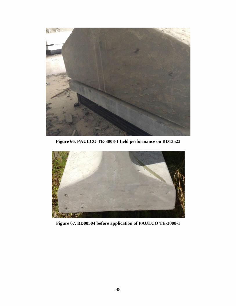
PAULCO TE-3008-1
During field inspection, this coating alternative showed no signs of deterioration or problematic
areas on either of the two beams (BD13523 and BD08504) to which it was applied (see Figures
64 through 69). For both beams, all areas of concrete and the few exposed strand ends appeared
to be still well protected, with very little to no rust evident on the strands and no rust penetrating
the coating.

47
Figure 64. BD13523 before application of PAULCO TE-3008-1
Figure 65. PAULCO TE-3008-1 applied to BD13523
48
Figure 66. PAULCO TE-3008-1 field performance on BD13523
Figure 67. BD08504 before application of PAULCO TE-3008-1

49
Figure 68. PAULCO TE-3008-1 applied to BD08504
Figure 69. PAULCO TE-3008-1 field performance on BD08504
Sikagard 62
Although no particular bridge beams were coated with Sikagard 62 for this project, there were
several beams at the precast plant at the time the research team was installing the other coating
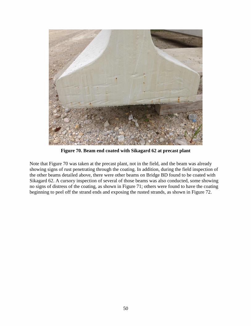
alternatives that had been previously coated with Sikagard 62. Figure 70 shows one example.
50
Figure 70. Beam end coated with Sikagard 62 at precast plant
Note that Figure 70 was taken at the precast plant, not in the field, and the beam was already
showing signs of rust penetrating through the coating. In addition, during the field inspection of
the other beams detailed above, there were other beams on Bridge BD found to be coated with
Sikagard 62. A cursory inspection of several of those beams was also conducted, some showing
no signs of distress of the coating, as shown in Figure 71; others were found to have the coating
beginning to peel off the strand ends and exposing the rusted strands, as shown in Figure 72.

51
Figure 71. Good field performance of Sikagard 62 on bridge beams
Figure 72. Poor field performance of Sikagard 62 on bridge beams
52
ALTERNATIVE BEAM-END DETAIL INVESTIGATION
The current specified preparation technique for prestressed concrete beams fabricated for use on
Iowa DOT bridges with expansion joints is to flush cut the strands at the beam ends and
subsequently apply the Sikagard 62 to the entire beam-end face, covering the exposed concrete
and cut-off strand ends. This procedure is similar to that specified by a few other states, while
most others choose to do nothing after flush cutting the strands. The main objective in coating
the beam ends is to prevent exposure of the beam ends to the elements. Another option for
protection of the prestressed beam ends and exposed strand ends is modification of the beam-end
detail during the fabrication process. The main goal of the modification would be to reduce the
exposure of the strand ends to the elements as much as possible, more so than with just an epoxy
or sealant.
Alternative Selection, Details, and Results
Prior to and during the development of these alternative beam-end details, input was sought from
the precaster’s perspective so as not to develop a forming alternative that was too complicated or
expensive to fabricate and utilize on a repeated basis. Based on input and recommendations from
the precasters and the TAC, the following beam-end alternatives were developed for evaluation:
Single Blockout – The region around the lower cluster of prestressing strands is blocked out,
thus creating a large void when the forms/foam are removed, then the blockout is filled with
grout or similar material.
Double Blockout – This detail is similar to the single blockout, except the blockout is split
into two smaller blockouts, one encompassing each strand cluster at the base of the beam.
The blockouts are filled with grout or similar material.
Bar Knockout (Burn Back and Patch) – Each strand is individually wrapped with a piece of
foam such that when the forms and foam are removed there is a pocket around each strand.
The strands within the pocket are cut off and/or burned back, and voids are filled with grout
or similar material. Note that this method has been utilized by the prestressing industry in the
past.
Drill Out Strands – The strand ends are flush cut and then 1 to 2 in. of the strands are drilled
out into the concrete.
All of these alternatives were only evaluated on the bottom flange of a standard Iowa DOT
prestressed concrete T-section to reduce the size of the laboratory specimens and improve
handling during testing. Figure 73 illustrates the lab specimen formwork prior to the concrete
pour. For the termination of the strand ends on these specimens, most were flush cut with a cut-
off wheel on the specimens with the larger blockouts; for the Bar Knockout specimen, the
strands were first flush cut with a cut-off wheel and then burned back into the recess using a
torch.

53
Figure 73. Formwork for laboratory beam-end specimens
Single Blockout
This beam-end forming alternative involves creating a blockout in the area surrounding the
cluster of prestressing strands such that when the forms and blockout material are removed the
area around the strands is recessed from the face of the girder a predetermined distance. This
recess allows for the strands to be cut off back from the face of the girder and covered for
protection. Three different blockout options were evaluated for the Single Blockout alternative:
(1) 1 in. thick foam blockout, (2) 2 in. thick foam blockout, and (3) ¾ in. plywood blockout with
chamfered edges. Figures 74 through 76 illustrate the three Single Blockout alternative
specimens, both prior to and after concrete placement.
The foam blockout was very simple to fabricate and did not result in any complications when
passing the prestressing strands through the ends of the formwork. Two methods were
investigated for creating the holes in the foam for passage of the strands: drilling out the foam
through the form end with a drill bit and marking the location of each strand on the inside of the
foam and simply pushing the strand through the foam and formwork. Both methods worked
adequately, although the first option was slightly more construction friendly because the strands
slid through much easier with the hole already in place in the foam. On these specimens, the
foam was attached to the formwork using a basic spray-on adhesive and presented no issues.
As can be seen in Figures 74 through 76, none of the blockouts created using foam had
chamfered edges.

54
Figure 74. Single Blockout formed with 1 in. foam
Figure 75. Single Blockout formed with 2 in. foam
Figure 76. Single Blockout formed with ¾ in. plywood with chamfered edges

55
When foam is used for this type of blockout, there is no need to chamfer the edges because
removal of the end formwork is similar to a standard beam casting. The foam, which typically
remains encased in the blockout around the strands, is then simply blasted or picked out quite
easily. Note that the strands located in the corners of the blockouts were difficult to remove and
cut completely flush with the concrete due to the tight radius of the blockout. In addition, on the
2 in. thick blockout the cluster of strands on the right side was cut flush to the concrete, whereas
the strands in the left-hand cluster were cut off at approximately 1 in. to evaluate whether this
had an effect on constructability, as well as what effect it may have on the bonding of the grout.
Constructability was slightly improved by only cutting off half of the protruding strand length
rather than flush cutting the strands in the blockout.
When the blockout was created using plywood or another stiff forming material (i.e., steel),
removal of the end formwork became extremely difficult, if not impossible, with some form of
damage being done to the formwork, without the chamfers around the edges of the blockout.
Even with the chamfer, removal of the formwork was problematic and cumbersome because both
the end form and the blockout must be slid over the numerous protruding strands simultaneously.
Lastly, it is worth noting that the chamfer in the blockout did facilitate easier cutting/removal of
the prestressing strands in the corners of the blockouts. However, further investigation may be
necessary to see what long-term effects the chamfer may have on the bond of the grout because
any cracking at the interface between the grout and the existing concrete could subsequently
funnel moisture (possibly containing chlorides) into the blockout and to the strand ends.
Double Blockout
This blockout alternative is a derivative of the Single Blockout alternative, in that two individual
blockouts are created around the main clusters of strands and separated along the vertical
centerline of the beam (see Figure 77).
Figure 77. Double Blockout formed with 1 in. foam
This blockout alternative was only evaluated using 1 in. foam for the construction method, and
the strands were all flush cut. Much like the Single Blockout alternative, the strands in the four

56
corners of the blockout were extremely problematic to cut given the blockout geometry.
Therefore, a slight revision of the blockout geometry may be necessary if used in the future. On
the positive side, this alternative has its advantages when applying the grout because there is less
of a void to fill, which in vertical applications like this can be an important aspect.
Bar Knockout (Burn Back and Patch)
As noted previously, this method has been used previously by the precaster in limited
applications. For this testing, the individual bar knockouts were created using ¾ in. self-sealing
tubular foam pipe insulation (see Figure 78).
Figure 78. Bar knockout using pipe insulation cut to 2 in. lengths
The tubing was first cut into 2 in. long pieces and then trimmed slightly along its length to create
a tight fit around the 0.6 in. diameter prestressing strands. In most cases, the self-sealing
adhesive was not sufficient to affix the foam to the strands and was therefore lightly taped closed
to keep the foam on the strand during concrete placement. For future applications, an un-slit
foam with an inside diameter more closely matching the diameter of the strands would be a more
construction friendly alternative. Even so, fabrication of this specimen was very construction
friendly and produced great results when the formwork and foam were removed.
Once the concrete was poured and the end formwork was removed, the foam was easily removed
from around the strands. The strands were then cut off nearly flush with the beam-end face using
a cut-off wheel and then burned back into the pockets using a torch. Burning back of the strands
did produce some slag on the insides of the pockets. However, this was easily removed with
either a pick or by sandblasting. It is worth noting that sandblasting the slag out created an
attractive roughed concrete surface for bonding of the grout material.

57
Drill Out Strands
The objective of this alternative was to avoid the necessity for any blockouts in the formwork but
still allow for the ends of the prestressing strands to be recessed, covered, and protected from
exposure to the elements at the ends of the beam. The basic procedure was to flush cut the
prestressing strands with the end of the beam and then, utilizing a drill bit, drill out 1–2 in. of the
prestressing strand into the concrete. Once the strand was drilled out, the void was filled with
grout.
Expectations were high for this method to be a viable beam-end detailing option. However,
shortly after the first drill attempt it was clear the simplicity of this method ended in the concept.
Numerous attempts were made, varying the procedure from attempting to drill a starter/pilot hole
with a smaller bit then switching to a larger bit, to center punching and beginning with the end
diameter (~0.5 in.) bit, then varying the drill bit material type, and even varying drill speed and
lubrication. Throughout the investigation, the best outcome was a 1/8 in. deep pilot hole using a
1/8 in. bit. On the laboratory specimen, which had untensioned strands, the individual strands
that form the woven strand were not tight enough against one another, resulting in a significant
amount of vibration during drilling. It is unknown if this issue would be resolved with a
tensioned strand. Regardless of this fact, no measurable amount of strand was successfully
drilled out using any method or drill bit type. Furthermore, it is believe that with the high cost of
the drill bits required for this type of application and the sheer number of them that would be
required (many drill bits would likely be required for just one beam-end treatment), this would
not be a construction friendly nor cost-effective option.
Beam-End Grouting Investigation
Although the main focus was to develop the beam-end forming alternatives for reducing
exposure of the strand ends to the elements, several non-shrink grouts were also evaluated for
their ability to fill the voids and encase the strand ends. Given project time limitations, only a
short-term evaluation of the performance (ability to apply to vertical surface, bond, etc.) of the
grout alternatives in the patch areas was feasible. Selection of the grouts for inclusion in this
testing was based on the following two main criteria: the material must be non-shrink and the
material must not require formwork and must be able to be applied in overhead or vertical
applications. Subsequently, three alternative grout products were selected: Sikacrete 211 SCC
Plus, Garon TIGERCRETE SP, and UNIQUE Overhead and Vertical Repair.
Application, Constructability, and Performance
All three grout products were mixed according to manufacturer specifications with a batch size
of approximately 0.5 cu ft using a 5-gallon bucket and paddle mixer and hand drill. The three
alternatives were evaluated either in the Single Blockout or Double Blockout configuration
because these larger voids were believed to be the worst case scenario in terms of
constructability in placement and performance of the grout. Both the Sikacrete 211 SCC Plus and
Garon TIGERCRETE SP products were evaluated on the Double Blockout configuration, one
alternative in each individual blockout on the beam end. For the UNIQUE Overhead and Vertical

58
Repair, the manufacturer provided four different mixes of the same product in an attempt to best
match the grout performance with the application. Therefore, each of the four UNIQUE mixes
was evaluated on either a 1 in. or 2 in. thick single blockout.
The beam-end specimens were all sand blasted prior to grouting to create an adequate bonding
surface and remove any rust/residue from the strand ends and then conditioned to saturated
surface dry (SSD) immediately prior to installing the grouts. Placement of the grout patches, for
both the Sikacrete 211 SCC Plus and Garon TIGERCRETE SP as well as the last three mixes
from UNIQUE, began with first scrubbing the void area to be filled with a slurry coat of the
respective grout mix using a stiff brush. After letting the slurry coat set for approximately one
minute, the remainder of the void was filled with the grout using a basic hand trowel. The void
was packed and troweled until the entire void was full and relatively flush with the face of the
beam end. In total, the grouting process took approximately five to eight minutes from the
beginning of the slurry coat to the final troweling of the grout patch.
From a constructability standpoint, all the grout products were easy to mix and were easily
placed into the vertical voids using a basic hand trowel, as previously mentioned. Given the
relatively short set time of these types of products, it seems unlikely that a batch much bigger
than that required for two to three beam ends, which ideally would be seated adjacent to each
other in the precast yard, could be managed without several skilled laborers on hand to quickly
place the grout. As for short-term performance (i.e., days and weeks), performance of the three
grout products was pretty even across the board, with all of them developing some level of
cracking within and/or around the patch area (see Figures 79 through 81).
Figure 79. UNIQUE Overhead and Vertical Repair
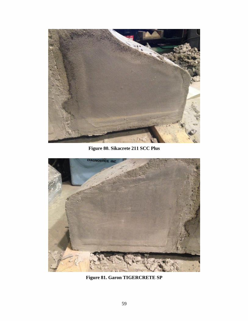
59
Figure 80. Sikacrete 211 SCC Plus
Figure 81. Garon TIGERCRETE SP

60
Typically, the cracks were first visible within a few days of grout placement and after a week or
so ceased progression. These cracks are believed to be shrinkage cracks, although the possibility
exists that microcracking could have existed in the beam-end specimens and reflected through
the grout patches.
In addition to the grout application evaluation, each grout patch alternative was allowed to cure
for 28 days and was then evaluated for bond performance by attempting to remove the grout
patch with an electric impact chisel. The results are described below.
For the UNIQUE product’s bond performance, recall that in the application of the first batch of
the UNIQUE Overhead and Vertical Repair the slurry coat step was mistakenly skipped.
Removal of this patch was subsequently found to be quite simple because little to no bond
between the existing concrete and the grout existed (see Figure 82).
Figure 82. UNIQUE Overhead and Vertical Repair – Batch 1 bond performance
The bond performance of the UNIQUE Overhead and Vertical Repair then began to improve
slightly throughout the mix progression. The second batch was found to have a good bond
between the slurry coat and the existing concrete but very little bond between the grout and the
slurry coat (Figure 83).

61
Figure 83. UNIQUE Overhead and Vertical Repair – Batch 2 bond performance
The third batch also had a good bond between the slurry coat and existing concrete, as well as a
better bond between the slurry and grout than the second batch (Figure 84).

62
Figure 84. UNIQUE Overhead and Vertical Repair – Batch 3 bond performance
The final batch of the UNIQUE Overhead and Vertical Repair had the best performance in terms
of bond, with good bond performance all around (Figure 85).
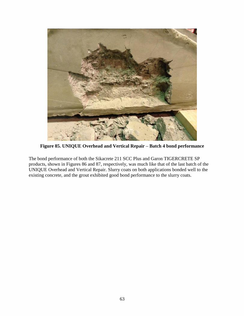
63
Figure 85. UNIQUE Overhead and Vertical Repair – Batch 4 bond performance
The bond performance of both the Sikacrete 211 SCC Plus and Garon TIGERCRETE SP
products, shown in Figures 86 and 87, respectively, was much like that of the last batch of the
UNIQUE Overhead and Vertical Repair. Slurry coats on both applications bonded well to the
existing concrete, and the grout exhibited good bond performance to the slurry coats.

64
Figure 86. Sikacrete SCC 211 Plus bond performance
Figure 87. Garon TIGERCRETE SP bond performance

65
CONCLUSIONS AND RECOMMENDATIONS
Currently, the Iowa DOT specifies that the ends of precast, prestressed concrete beams used in
bridges constructed with expansion joints be finished at the precast plant according to the
precaster’s specified beam-end finishing procedures, and subsequently have a coating of
Sikagard 62 applied to the end of each beam. Although Sikagard 62 has been used by the Iowa
DOT as a beam-end coating product for years, no laboratory investigation related to the
effectiveness of this detail had been conducted, while anecdotally the performance of in-service
bridge beams that have undergone this end treatment process has been found to be highly
variable and substandard. Field inspections have found many bridge beams with rusty strand
ends exposed, others with spalling and deterioration of the beam ends.
The scope of work for this project incorporated a literature search of the current state of the art
and state of the practice, a laboratory evaluation of different concrete coating products utilizing
ponded concrete slabs and the AASHTO T259-80 test, and the development of several
experimental beam-end detailing alternatives. In addition, beam ends for two Iowa DOT bridges
planned for construction near the beginning of the project were also treated with the beam-end
coating alternatives evaluated on the ponding slabs and were visually monitored for the duration
of the project.
Previous research related to the performance of concrete beam-end treatments found that many
state DOTs do not treat the ends of their prestressed concrete beam ends, some do specify beam-
end treatment procedures, and a select few specify coating alternatives, although many if not all
of the procedures and products that were specified had little to no laboratory or field testing data
related to their use in these specific applications. Ultimately, previous research indicated that
further laboratory testing was warranted into this subject.
Laboratory ponding tests were conducted on eight different concrete treatment products that
were selected based on previous research, current product availability, and TAC
recommendations. The eight treatment products selected for evaluation were the following:
Sikagard 62, Evercrete DPS, TEXCOTE XL 70 BRIDGE COTE, TEXCOTE RAINSTOPPER
140, BASF Sonoguard, BASF Hydrozo 100, Viking Agua Guard, and PAULCO TE-3008-1. The
alternatives were applied to a designated reference square on three separate concrete slabs, each
cast at a different precast plant near central Iowa so that the effect of different concrete mixes
could also be evaluated. The ponding slabs were evaluated using the AASHTO T259-80 chloride
penetration test, and throughout the project all three slabs were subjected to a 90-day ponding
cycle, the slabs were then dried, and samples were taken. The process was repeated two more
times. In general, over the course of the three ponding cycles there was little to no difference
found in the chloride content test results for any of the alternatives; thus, no significant benefit or
detriment to the coating’s performance was evidenced due to the mix design of the concrete.
Comparison of the test data from the sections of the slab with applied coating alternatives to two
slab sections left uncovered, i.e., control sections, revealed a marked improvement in the
resistance to chloride penetration of the concrete, which was expected; the one exception was the
TEXCOTE XL 70 BRIDGE COTE, which the test data indicated did not improve the chloride
penetration resistance of the concrete compared to the control sections. The chloride ion

66
penetration performance of all the alternatives were then compared to one another and the
coating alternatives ranked in order from best to worst performance based on the ponding data:
(1) three-way tie: BASF Sonoguard, BASF Hydrozo 100, Sikagard 62 – two coats, (2) Viking
Aqua Guard Concrete Sealer, (3) Sikagard 62 – one coat, (4) TEXCOTE RAINSTOPPER 140,
(5) PAULCO TE-3008-1, (6) Evercrete DPS, (7) TEXCOTE XL 70 BRIDGE COTE with
Silane. Note that the Iowa DOT currently specifies application of one coat of Sikagard 62, per
the manufacturer’s recommendations. Addition of another coat of Sikagard 62 did slightly
improve the chloride ion penetration performance but likely not enough to warrant the extra time
and cost involved in the process.
A total of 19 bridge beam ends were treated with the concrete coating alternatives. Each beam
end was prepared according to the precaster’s specifications and then the alternative coating
applied according to the manufacturers’ recommendations. Approximately 18 months after the
beam ends had been treated and installed, field inspections were conducted to evaluate their
short-term performance. Inspection results from the beam ends treated with the coating
alternatives varied not only from product to product, but at times even from one beam to another
coated with the same alternative. In general, the performance of all of the alternatives on the
concrete surfaces of the beam ends was excellent. There were no signs of peeling or deterioration
of the coating on the concrete surfaces. All of the problems found during the field inspection
appeared to be centered in the areas of the prestressing strand locations. In the rare case where
there was a beam end that had all the prestressing strand ends covered as a result of the beam-end
preparation process and then having the coating applied, the beam end showed no signs of
deterioration. However, it was rarely the case that all the strand ends were covered after
completion of the preparation process. In most cases, several of the strand ends, and sometimes
numerous strand ends, were visible and found to be rusted immediately prior to the coating
alternative being applied. Note that all visible rust was removed prior to application of all coating
alternatives, although this is believed to be more a superficial fix than a long-term maintenance
plan. Further inspection of untrimmed and untreated beam ends at the precast plant found the
strands protruding from the ends of the beams to be heavily rusted, and because they are
uncovered and exposed to the elements it is highly likely that moisture (and subsequently rust)
migrated into the end of the beam end via the strands prior to any beam-end treatment. Possible
evidence of this is that there were three beam ends that were treated at the precast plan and less
than a week later had to be treated again because the precaster noted that they appeared to be
untreated and that there were visible signs of rust on the strand ends under the coatings.
Inspection by the research team found that they were treated properly the first time; still, rust had
developed and was visible. Subsequently, the strand ends were cleaned of rust and retreated a
second time prior to being installed in the field. The moisture and rust that is pre-existing within
the beam ends on the strands prior to application of the coating alternative is likely to blame for
most of the failures found on the bridge beams treated with the coatings evaluated for this work.
Some of the alternatives only had visible signs of rust on the strand ends, with no rust piercing
the coating, others had visible rust piercing the coating, and a few others had the coating peeling
off and missing completely from the strand ends.
Ultimately, the objective of treating the ends of prestressed concrete beams is to protect the
exposed concrete and strands at the end of the beam from exposure to moisture and chlorides,
which may penetrate the expansion joint and wreak havoc on the beam ends. In addition to

67
evaluating the coating alternatives, several beam-end forming details were also developed and
evaluated for their potential to mitigate this problem. In general, the solutions all centered around
creating a void, whether it be an individual void around each strand or a large void around a
cluster of strands, such that when the prestressing strands are cut back their ends are behind the
vertical face of the beam end. Each of the voids could then be grouted to cover and protect the
strand ends and the beam end treated in its traditional manner as a belts and suspenders solution.
Creation of the voids must be simple and meet constructability requirements for this type of
beam-end detail to ultimately be viable; the process must also not significantly increase the
workload during beam fabrication, or a precaster will lose interest or significantly raise costs. In
addition, if the detail is too elaborate and requires expensive form modifications, the precaster
might resist this option or force the buyer to forgo it due to the increased cost of the end product.
Based on these criteria, four alternative beam-end details were evaluated for this work: (1) single
beam-end knockout around the entire cluster of strands in the bottom flange of the beam, (2)
double beam-end knockout around the two clusters of strands in the bottom flange of the beam,
(3) individual strand knockouts around each strand in the bottom flange of the beam, and (4)
drilling out the strands.
Drilling out the strands after each is flush cut to the beam face was found to be a nearly
impossible process, which, if the process were to be successful, would require lots of labor and
expensive drill bits. Therefore, this alternative is not considered a viable option. However, any of
the blockout options—single, double, or individual bar—are all excellent options for creating a
separation from the face of the beam end and the end of the prestressing strand. Foam was found
to be the material of choice for creation of the voids because it allowed for easy installation of
both the void blockout and the strands, which could be easily pushed through the foam or
through predrilled holes in the foam. Once the forms are removed, the foam is easily removed
and the strands may then be cut back to any depth within the exterior face of the beam. Creation
of the blockout using plywood, or using metal via modification of a preexisting metal form,
would likely require that the outer boundaries of the blockout be chamfered to facilitate easy
removal of the forms without damaging the concrete beam end. The final step in the process was
to fill the blockouts with a non-shrink grout to protect the ends of the strands. Several grout
products were evaluated for this project, including Sikacrete SCC Plus, Garon TIGERCRETE,
and UNIQUE Paving Overhead and Vertical Repair. All three products provided an adequate
bond to the existing concrete and were easy to mix and apply into the vertical voids regardless of
their depth or size. However, even though all products are “non-shrink” grouts, each of the three
products developed shrinkage cracks both within the boundaries of the voids and at the perimeter
of the voids within a few days of application. Further investigation into potential grout products
and/or epoxy products that can adequately fill the voided areas without cracking is warranted.


69
REFERENCES
Ahlborn, T. M., Kasper, J. M., Aktan, H., Koyuncu, Y., and Rutyna, J. 2001. Causes and Cures
of Prestressed Concrete I-Beam End Deterioration. Report No. CSD 2002-02. Center for
Structural Durability, Michigan Tech Transportation Institute, and Michigan Department
of Transportation (Report RC-1412), Lansing, MI.
Palle, S., and Hopwood, T. 2006. Coatings, Sealants, and Fillers to Address Bridge Concrete
Deterioration and Aesthetics – Phase I. Report No. KTC06-36/SPR291-04-1F. Kentucky
Transportation Center, Lexington, KY.
Radlinska, A., McCarthy, L., Yost, J. R., Matzke, J., and Nagel, F. 2012. Coating and
Treatments for Beam Ends. FHWA Report FHWA-PA-2012-002-100402. Pennsylvania
Department of Transportation, Harrisburg, PA.
Tabatabai, H., Ghorbanpoor, A., and Turnquist-Nass, A. 2005. Rehabilitation Techniques for
Concrete Bridges. Report Number WHRP 05-01. Wisconsin Highway Research Program,
Madison, WI.