Embed Size (px)
Citation preview
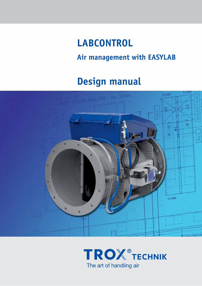
Air management with EASYLAB
Design manual
LABCONTROL
2
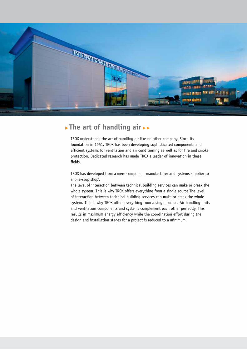
▶The art of handling air ▶▶
TROX understands the art of handling air like no other company. Since its foundation in 1951, TROX has been developing sophisticated components and efficient systems for ventilation and air conditioning as well as for fire and smoke protection. Dedicated research has made TROX a leader of innovation in these fields.
TROX has developed from a mere component manufacturer and systems supplier to a 'one-stop shop'.The level of interaction between technical building services can make or break the whole system. This is why TROX offers everything from a single source.The level of interaction between technical building services can make or break the whole system. This is why TROX offers everything from a single source. Air handling units and ventilation components and systems complement each other perfectly. This results in maximum energy efficiency while the coordination effort during the design and installation stages for a project is reduced to a minimum.
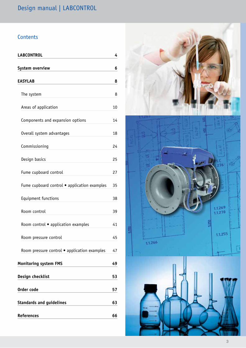
Contents
LABCONTROL 4
System overview 6
EASYLAB 8
The system 8
Areas of application 10
Components and expansion options 14
Overall system advantages 18
Commissioning 24
Design basics 25
Fume cupboard control 27
Fume cupboard control • application examples 35
Equipment functions 38
Room control 39
Room control • application examples 41
Room pressure control 45
Room pressure control • application examples 47
Monitoring system FMS 49
Design checklist 53
Order code 57
Standards and guidelines 63
References 66
Design manual | LABCONTROL
3
4
LABCONTROL
Air handling technology is of decisive importance in sensitive areas such as laboratories, hospitals, research institutes, livestock facilities or in clean room technology. Without a functioning and reliable ventilation system, these areas would not be able to function correctly.
For many years, TROX has dealt with these special requirements, is a member of the standardisation committees for these areas and provides the appropriate components for achieving the relevant objectives. A market success for almost 15 years, the LABCONTROL system, which is constantly adapted to the demands of the market and successfully used in laboratories, is a prime example. The experience gained from project meetings and from the development of these projects help us transform new requirements into innovations.
Municipal Hospital, Düsseldorf, Germany
Principal advantages of LABCONTROL controllers• Double function test:1. Check of the electronic control component (controller)2. Check of the airflow on the VAV terminal unit including
controller• Factory setting of all volume flow rate ranges and
functions for all controllers as defined in the order• Certification of the fume cupboard controllers to
EN 14175, part 6, by an independent testing authority• Experience gained from more than 60,000 installed
LABCONTROL volume flow controllers worldwide
Bayer HealthCare AG, Wuppertal, Germany
5
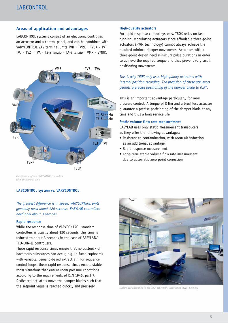
Areas of application and advantages
LABCONTROL systems consist of an electronic controller, an actuator and a control panel, and can be combined with VARYCONTROL VAV terminal units TVR · TVRK · TVLK · TVT · TVJ · TVZ · TVA · TZ-Silenzio · TA-Silenzio · VMR · VMRK.
Combination of the LABCONTROL controllerswith air terminal units
LABCONTROL system vs. VARYCONTROL
The greatest difference is in speed. VARYCONTROL units generally need about 120 seconds. EASYLAB controllers need only about 3 seconds.
Rapid responseWhile the response time of VARYCONTROL standard controllers is usually about 120 seconds, this time is reduced to about 3 seconds in the case of EASYLAB/ TCU-LON-II controllers.These rapid response times ensure that no outbreak of hazardous substances can occur, e.g. in fume cupboards with variable, demand-based extract air. For sequence control loops, these rapid response times enable stable room situations that ensure room pressure conditions according to the requirements of DIN 1946, part 7. Dedicated actuators move the damper blades such that the setpoint value is reached quickly and precisely.
High-quality actuatorsFor rapid response control systems, TROX relies on fast-running, modulating actuators since affordable three-point actuators (PWM technology) cannot always achieve the required minimal damper movements. Actuators with a three-point design need minimum pulse durations in order to achieve the required torque and thus prevent very small positioning movements.
This is why TROX only uses high-quality actuators with internal position recording. The precision of these actuators permits a precise positioning of the damper blade to 0.5°.
This is an important advantage particularly for room pressure control. A torque of 8 Nm and a brushless actuator guarantee a precise positioning of the damper blade at any time and thus a long service life.
Static volume flow rate measurementEASYLAB uses only static measurement transducers as they offer the following advantages:• Resistant to contamination, with room air induction
as an additional advantage• Rapid response measurement• Long-term stable volume flow rate measurement
due to automatic zero point correction
System demonstration in the TROX laboratory, Neukirchen-Vluyn, Germany
LABCONTROL
TVRK
VMR
VMRK
TVLK
TA-SilenzioTZ-Silenzio
TVR
TVJ · TVT
TVZ · TVA
6
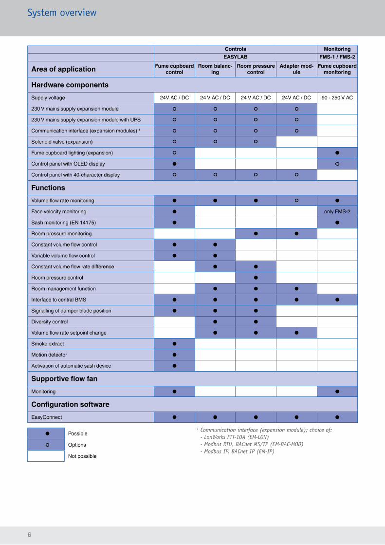
System overview
Controls MonitoringEASYLAB FMS-1 / FMS-2
Area of application Fume cupboard control
Room balanc-ing
Room pressure control
Adapter mod-ule
Fume cupboard monitoring
Hardware componentsSupply voltage 24V AC / DC 24 V AC / DC 24 V AC / DC 24V AC / DC 90 - 250 V AC
230 V mains supply expansion module
230 V mains supply expansion module with UPS
Communication interface (expansion modules) 1
Solenoid valve (expansion)
Fume cupboard lighting (expansion) ●
Control panel with OLED display ●
Control panel with 40-character display
FunctionsVolume flow rate monitoring ● ● ● ●
Face velocity monitoring ● only FMS-2
Sash monitoring (EN 14175) ● ●
Room pressure monitoring ● ●
Constant volume flow control ● ●
Variable volume flow control ● ●
Constant volume flow rate difference ● ●
Room pressure control ●
Room management function ● ● ●
Interface to central BMS ● ● ● ● ●
Signalling of damper blade position ● ● ●
Diversity control ● ●
Volume flow rate setpoint change ● ● ●
Smoke extract ●
Motion detector ●
Activation of automatic sash device ●
Supportive flow fanMonitoring ● ●
Configuration softwareEasyConnect ● ● ● ● ●
● Possible
Options
Not possible
1 Communication interface (expansion module); choice of:- LonWorks FTT-10A (EM-LON)- Modbus RTU, BACnet MS/TP (EM-BAC-MOD)- Modbus IP, BACnet IP (EM-IP)
7
System overview
System selectionEASYLAB
EASYLAB controller with expansion modules
Area of application• Control of fume cupboards, supply air, extract air and pressure• TROX adapter module (TAM) as group controller
Hardware• Modular, expandable hardware structure
– For 230 V AC power supply, also with UPS – Automatic zero point correction – Communication interface for a single controller or for the room – LonWorks FTT-10A – BACnet IP or MS/TP – Modbus IP or RTU
• Casing design with external connections and signalling functions
• Plug-in communication cable• Adaptive control panels with service connection for fume
cupboards and room control
Special functions• Flexible room control strategies• Automatic or individual splitting of room supply and extract
air volume flow rates when several controllers of the same type are used
• Damper blade position signalling• Configurable error display and signalling (consolidated alarms)
Commissioning• Easy commissioning and expansion
– due to plug and play components for the various controller types
– no component addressing required• Room management function for centralised configuration
and signalling of room settings• Controller configuration using EasyConnect software
with interactive commissioning sequence
Controls MonitoringEASYLAB FMS-1 / FMS-2
Area of application Fume cupboard control
Room balanc-ing
Room pressure control
Adapter mod-ule
Fume cupboard monitoring
Hardware componentsSupply voltage 24V AC / DC 24 V AC / DC 24 V AC / DC 24V AC / DC 90 - 250 V AC
230 V mains supply expansion module
230 V mains supply expansion module with UPS
Communication interface (expansion modules) 1
Solenoid valve (expansion)
Fume cupboard lighting (expansion) ●
Control panel with OLED display ●
Control panel with 40-character display
FunctionsVolume flow rate monitoring ● ● ● ●
Face velocity monitoring ● only FMS-2
Sash monitoring (EN 14175) ● ●
Room pressure monitoring ● ●
Constant volume flow control ● ●
Variable volume flow control ● ●
Constant volume flow rate difference ● ●
Room pressure control ●
Room management function ● ● ●
Interface to central BMS ● ● ● ● ●
Signalling of damper blade position ● ● ●
Diversity control ● ●
Volume flow rate setpoint change ● ● ●
Smoke extract ●
Motion detector ●
Activation of automatic sash device ●
Supportive flow fanMonitoring ● ●
Configuration softwareEasyConnect ● ● ● ● ●
8
EASYLABThe system
Innovations at a glance
During early project meetings and discussions with specialist consultants, system designers and users of our systems, the desire for simplified assembly, wiring, commissioning and maintenance as well as the expandability of the system was of particular importance.
This was the basis for the EASYLAB system, which takes these requirements into consideration and implements them as described below:
EASY
LAB
Hardware• Modular controller hardware
Regardless of whether you need a LonWorks, BACnet or Modbus connection, whether 230 V AC supply with or without uninterruptible power supply (UPS), a volume flow rate transducer with or without automatic zero point correction, or a lighting connection for your fume cupboard, and regardless of whether you rely on a bluff body or a Venturi nozzle for volume flow rate measurement, EASYLAB offers individual configuration options to meet your needs.
• Plug-in communication cableThe controllers can be interconnected with a cable that can be plugged into the outside of the casing.
• New casing concept – Installation and connection of all expansion modules – External plug sockets for the most important function expansions
• Adaptive control panels with service connection for fume cupboards and room controlDisplays for room control or fume cupboard control can be individually adapted to project requirements. In addition, they automatically adapt to the operating situation, thereby facilitating ease of use even in complex cases.
• TROX adapter module (TAM)Provision of a hardware interface for room solutions with fume cupboards in combination with conventional room controllers using analog technology. TAM provides options for – room balancing – connection of the EASYLAB room control panel – integration with the central BMS
TROX EASYLAB
9
EASYLABThe system
Functions
• Automatic splitting of volume flow ratesIf more than one room controller is installed, the volume flow rates are automatically distributed across all controllers in the room.
• Room control is an integral part of the systemEASYLAB allows for displaying and presetting of operating modes and room information using a control panel. This is conveniently coordinated with the extensive capabilities of the system.
• Signalling of damper blade positions to increase energy efficiencyTo optimise the fan speed, damper blade positions can be signalled to the central BMS (selective point measurement).
• Selective diversity controlRefined control strategy for maintaining work safety at as many workstations as possible when the total extract air determined during design is exceeded.
• Reduction of unnecessary extract air volume flow ratesOptimised safety strategy for extract air distribution.
RMF
Room operating mode
Setpoit change signal
Temperature
Signalling
Room control panel
Room alarms
Interface central BMS/room
Setpoint valueRoom pressure
Default values
Actual valueRoom pressure
Minimum total extract air
Commissioning
• Simple commissioning methodThe system needs only one communication cable to connect the individual controllers. No functional assignment between the individual controller types of a room is required. The addressing otherwise needed in the case of a communication network is completely unnecessary with EASYLAB. After the communication cable is plugged in, all connected controllers are recognised and immediately exchange all required operating data.
• Interactive controller configuration and maintenanceUsers are guided through the new configuration software in easy-to-follow steps. The software supports commissioning to finished controller configuration as well as a typical maintenance run, including PDF report.
• Wireless commissioningIn addition to the intuitive commissioning concept, optional wireless access simplifies configuration and maintenance of the controller.
• Centralised default settings using the room management function (RMF)Default settings affecting an entire room can be entered centrally on one controller or TAM, which then assumes the room management function. This offers excellent advantages in installation, commissioning, and maintenance.
• Other available functions: – Optimised extract air balancing – Control input signal for air terminal devices, blinds or sashes
– Supply air led system for clean rooms
10
EASYLABAreas of application
Area of application and function of EASYLAB controllersThe electronic EASYLAB TCU3 controller is designed for special control functions related to volume flow rate control and can be used with the following VAV terminal units: TVLK · TVRK (PP plastic) or TVR · TVT · TVJ · TVZ · TVA · TZ-Silenzio · TA-Silenzio · VMR · VMRK (galvanised sheet steel, with optional powder coating, or stainless steel construction).
EASYLAB controllers can be set up individually or combined into a system. The following functions are hence available:
Volume flow controlEssential features of the EASYLAB system include improved volume flow rate balancing for all types of room scenarios and the volume flow rate control of fume cupboards. In addition to the precise recording of actual volume flow rates, stable control requires the exact and rapid control to achieve the setpoint values.
Fume cupboard controlFume cupboards have a special function when it comes to protecting the staff in a lab. Main goals are retention and air change. EASYLAB covers all the usual control options and meets, hence, all individual requirements.
Functions:• Volume flow control with constant value (one-point)• Two-point or three-point control• Fully variable control using a sash distance sensor,
linear function or optimised safety function• Variable control using a sash distance sensor
(optimised safety function)• Fully variable control using a face velocity transducer• Function monitoring and display according to
EN 14175 • Connection of a motion detector• Activation of an automatic sash device• Fume cupboards with supportive flow technology• Extract air scrubber activation• Smoke extract• Fume cupboard lighting
Pressure controlThe typical areas of application for our systems increasingly include areas with room or duct pressure control. Both control strategies can be fulfilled with EASYLAB, which provides comprehensive, specially adapted control functions. Cascade control rather than differential pressure control with a damper blade allows for much more stable room situations even with quick-response volume flow control loops.
Dedicated research and development have resulted in electronic control solutions for situations that could previously only be controlled with alternative systems.
Signal transducers are available for application areas for which certified room pressure transducers are required (GMP).EASYLAB controllers with uninterruptible power supply (optional) maintain the control functions and hence the room pressure for up to four hours in case of a power failure.
EASYLAB controllers combined with VAV terminal units
TVRK
VMR
VMRK
TVLK
TA-SilenzioTZ-Silenzio
TVR
TVJ · TVT
TVZ · TVA
11
ALTANA BYK-Chemie, Wesel, Germany
EASYLABAreas of application
External pressure controlEASYLAB enables not only independent pressure control but also room pressure control through an external volume flow rate setpoint change. The required change signal can come from an analog input or from a communication module.
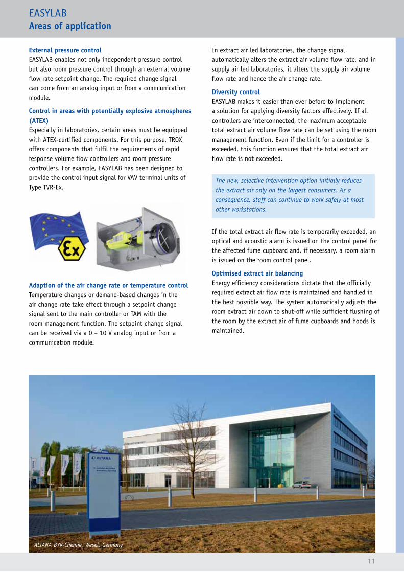
Control in areas with potentially explosive atmospheres (ATEX)Especially in laboratories, certain areas must be equipped with ATEX-certified components. For this purpose, TROX offers components that fulfil the requirements of rapid response volume flow controllers and room pressure controllers. For example, EASYLAB has been designed to provide the control input signal for VAV terminal units of Type TVR-Ex.
Adaption of the air change rate or temperature controlTemperature changes or demand-based changes in the air change rate take effect through a setpoint change signal sent to the main controller or TAM with the room management function. The setpoint change signal can be received via a 0 – 10 V analog input or from a communication module.
In extract air led laboratories, the change signal automatically alters the extract air volume flow rate, and in supply air led laboratories, it alters the supply air volume flow rate and hence the air change rate.
Diversity controlEASYLAB makes it easier than ever before to implement a solution for applying diversity factors effectively. If all controllers are interconnected, the maximum acceptable total extract air volume flow rate can be set using the room management function. Even if the limit for a controller is exceeded, this function ensures that the total extract air flow rate is not exceeded.
The new, selective intervention option initially reduces the extract air only on the largest consumers. As a consequence, staff can continue to work safely at most other workstations.
If the total extract air flow rate is temporarily exceeded, an optical and acoustic alarm is issued on the control panel for the affected fume cupboard and, if necessary, a room alarm is issued on the room control panel.
Optimised extract air balancingEnergy efficiency considerations dictate that the officially required extract air flow rate is maintained and handled in the best possible way. The system automatically adjusts the room extract air down to shut-off while sufficient flushing of the room by the extract air of fume cupboards and hoods is maintained.
12
EASYLABAreas of application
Fan control based on damper blade positionsMost central systems include a variable speed control for fans. This makes sense in case of variable volume flow control since with constant fan speed the duct pressure rises or falls depending on the volume flow rate. Negative effects include high levels of air-regenerated noise and increased operating costs due to the decreasing specific fan power (SPF).In extensive duct systems, the duct pressure control, which should ideally also 'control' the fan using a frequency inverter, often has the disadvantage that areas with too little duct pressure start to occur in different parts of the ducting. This is why the static pressure should be measured at different points in the ductwork rather than directly on the ventilation unit.There is also a tendency to use the damper blade positions of the VAV terminal units as selective point signals in order to determine the necessary fan speed or the duct pressure.EASYLAB supports this control approach and provides information on the individual damper blade positions or an evaluated signal from up to 24 controllers per room. This can considerably reduce the data points needed and thus help save costs.
Bayer Pharma Pharmaceutical Research Centre, Wuppertal, Germany
Operating modes and room control strategyEASYLAB supports the following operating modes:• Standard mode, e.g. as day-time operation with 8 air
changes per hour• Reduced operation, e.g. as night-time setback or as
office operation with reduced air change rate• Increased operation, e.g. in an emergency, with
increased air change rate• Shut-off mode (damper blade is closed), e.g. for system
shutdown• OPEN mode of the controllers• Pressure reversal, e.g. change between negative and
positive pressure in hospital areas (septic/aseptic)
Room control is often neglected in the design stage. Many systems, however, cannot fully adjust to changed requirements at a later stage.
In times when everyone is talking about 'Green Building', users or room occupants should have the chance to actively influence the energy use.
For this purpose, EASYLAB includes room control panels that provide important information regarding air distribution and allow users to influence it. It was a primary goal in the development of the EASYLAB operating mode concept to make the system easy to use and to provide versatile adjustment options for various project requirements.
13
EASYLABAreas of application
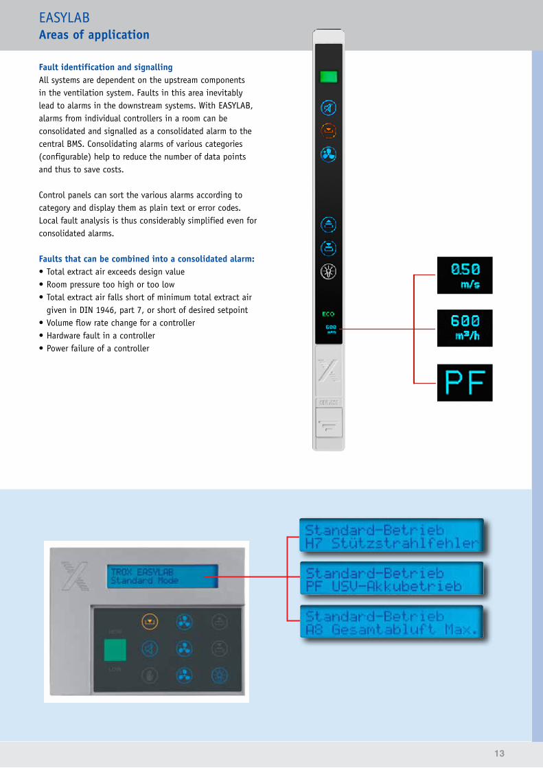
Fault identification and signallingAll systems are dependent on the upstream components in the ventilation system. Faults in this area inevitably lead to alarms in the downstream systems. With EASYLAB, alarms from individual controllers in a room can be consolidated and signalled as a consolidated alarm to the central BMS. Consolidating alarms of various categories (configurable) help to reduce the number of data points and thus to save costs.
Control panels can sort the various alarms according to category and display them as plain text or error codes. Local fault analysis is thus considerably simplified even for consolidated alarms.
Faults that can be combined into a consolidated alarm: • Total extract air exceeds design value• Room pressure too high or too low• Total extract air falls short of minimum total extract air
given in DIN 1946, part 7, or short of desired setpoint• Volume flow rate change for a controller• Hardware fault in a controller• Power failure of a controller
14
EASYLABComponents and expansion options
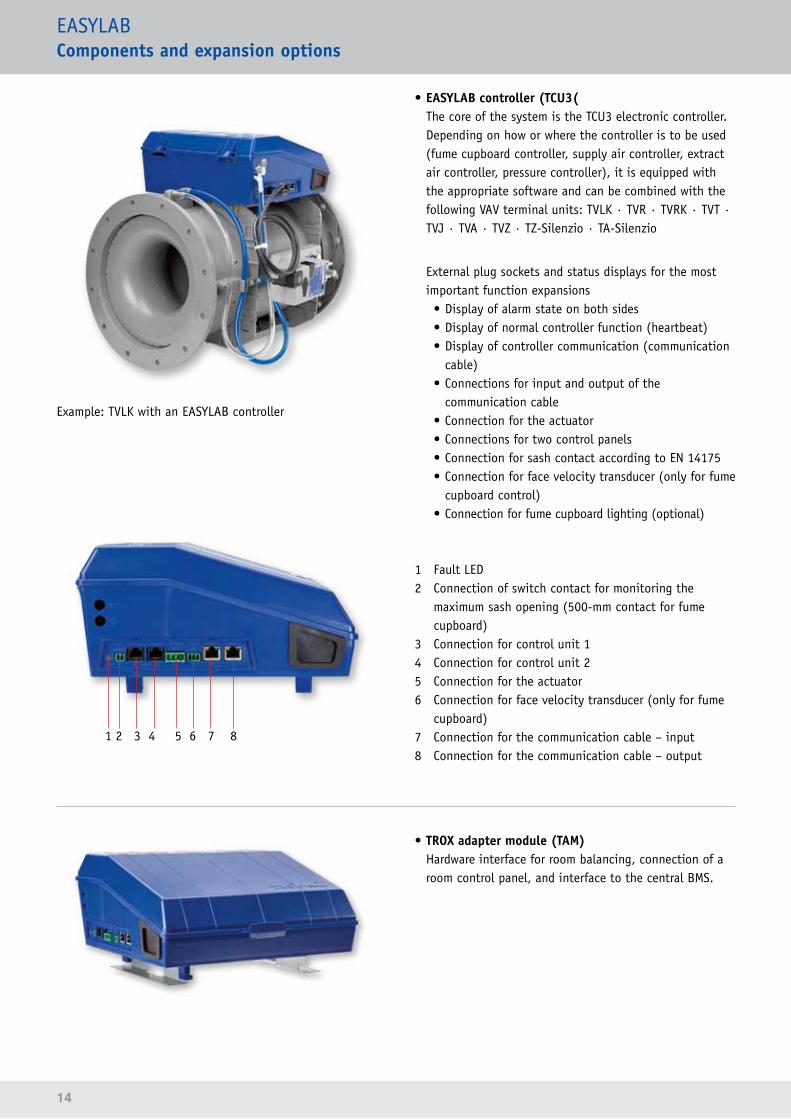
Example: TVLK with an EASYLAB controller
1 2 3 4 5 6 7 8
• EASYLAB controller (TCU3(The core of the system is the TCU3 electronic controller. Depending on how or where the controller is to be used (fume cupboard controller, supply air controller, extract air controller, pressure controller), it is equipped with the appropriate software and can be combined with the following VAV terminal units: TVLK · TVR · TVRK · TVT · TVJ · TVA · TVZ · TZ-Silenzio · TA-Silenzio
External plug sockets and status displays for the most important function expansions• Display of alarm state on both sides• Display of normal controller function (heartbeat)• Display of controller communication (communication
cable)• Connections for input and output of the
communication cable• Connection for the actuator• Connections for two control panels• Connection for sash contact according to EN 14175• Connection for face velocity transducer (only for fume
cupboard control)• Connection for fume cupboard lighting (optional)
1 Fault LED2 Connection of switch contact for monitoring the
maximum sash opening (500-mm contact for fume cupboard)
3 Connection for control unit 14 Connection for control unit 25 Connection for the actuator6 Connection for face velocity transducer (only for fume
cupboard)7 Connection for the communication cable – input8 Connection for the communication cable – output
• TROX adapter module (TAM)Hardware interface for room balancing, connection of a room control panel, and interface to the central BMS.
15
EASYLABComponents and expansion options
Modular hardware structureThe EASYLAB base components (TCU3 controller and TAM) can be expanded by various modules (optional):
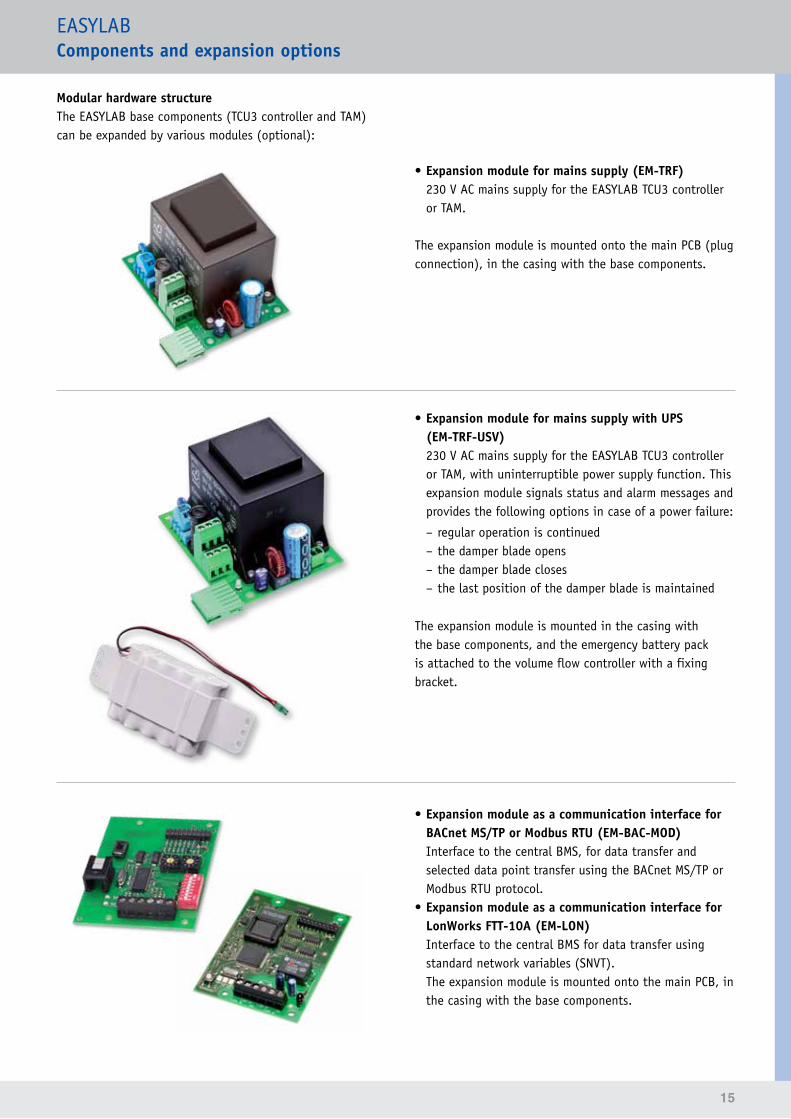
• Expansion module for mains supply (EM-TRF)230 V AC mains supply for the EASYLAB TCU3 controller or TAM.
The expansion module is mounted onto the main PCB (plug connection), in the casing with the base components.
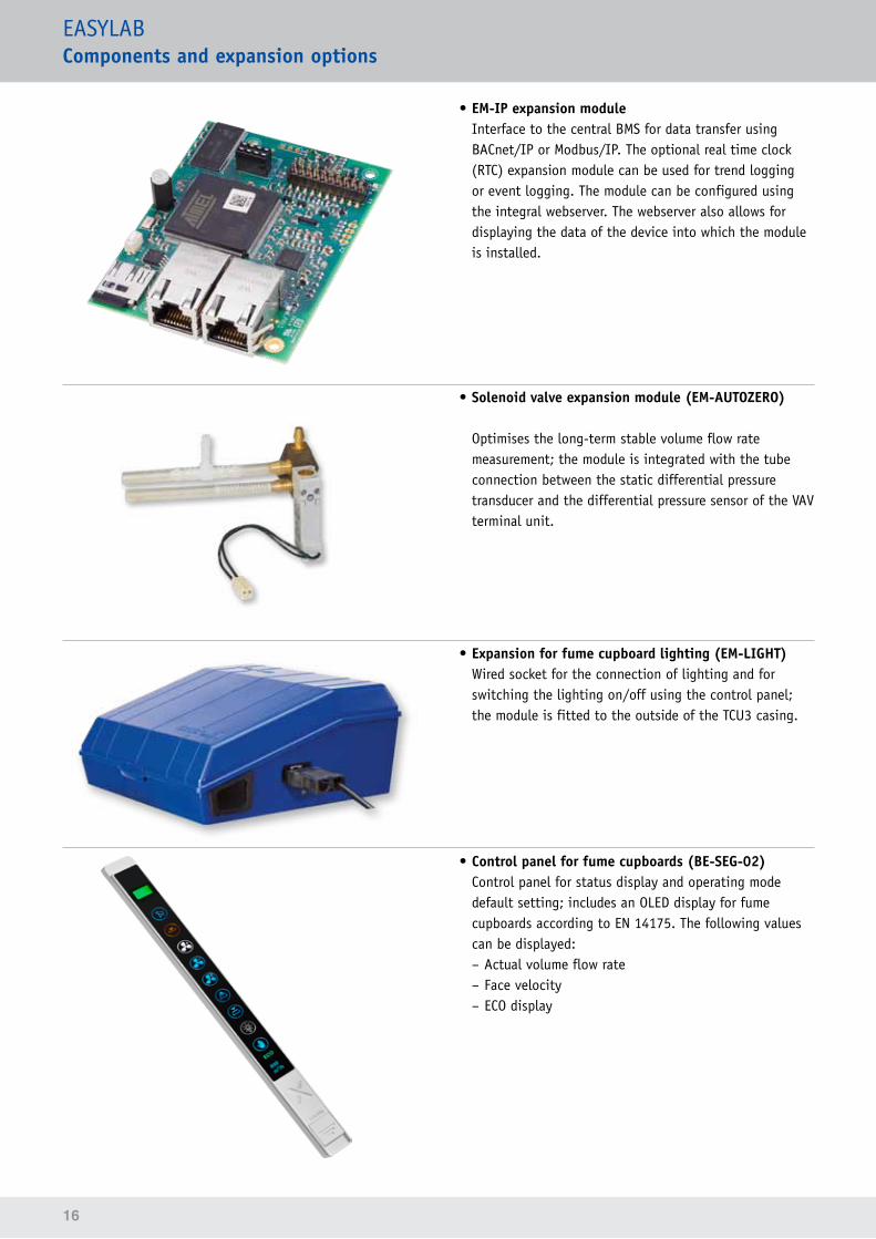
• Expansion module for mains supply with UPS (EM-TRF-USV)230 V AC mains supply for the EASYLAB TCU3 controller or TAM, with uninterruptible power supply function. This expansion module signals status and alarm messages and provides the following options in case of a power failure:
– regular operation is continued – the damper blade opens – the damper blade closes – the last position of the damper blade is maintained
The expansion module is mounted in the casing with the base components, and the emergency battery pack is attached to the volume flow controller with a fixing bracket.
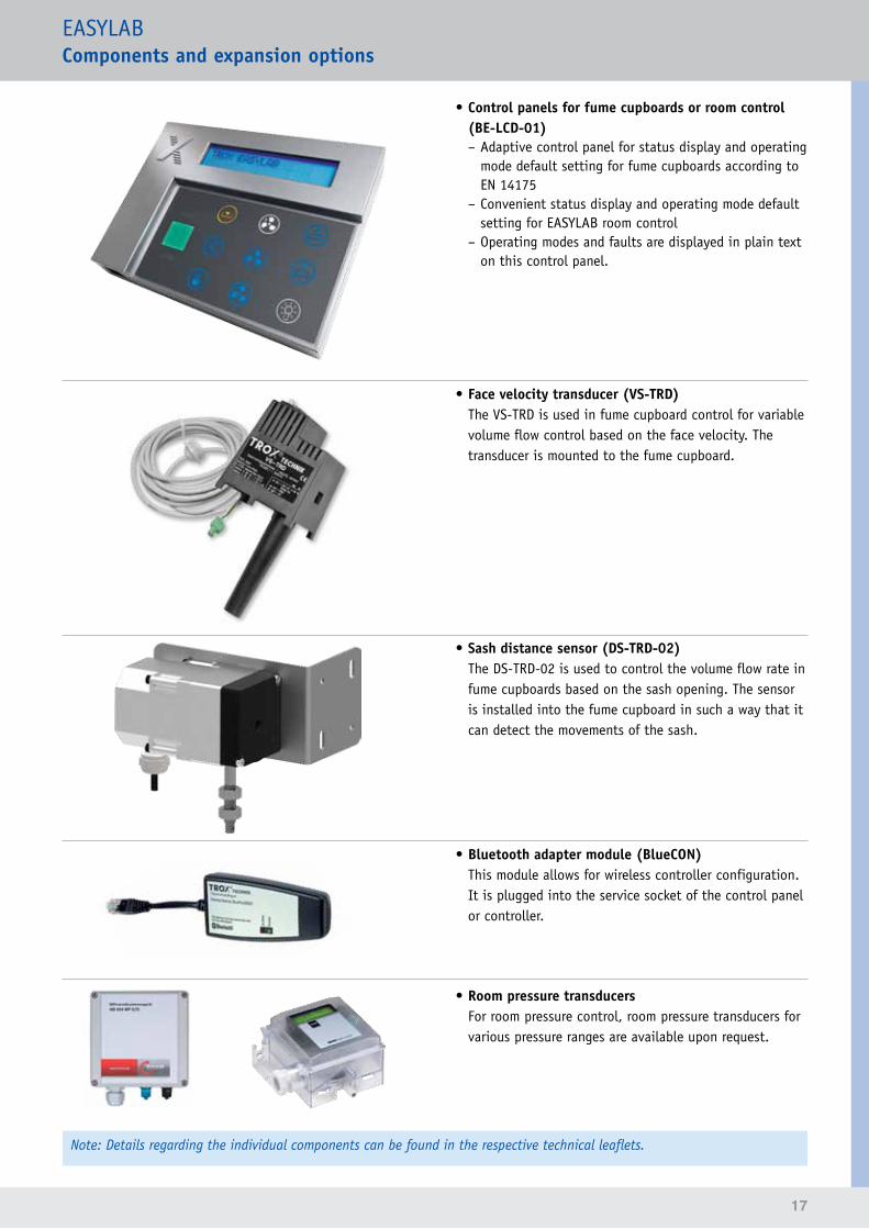
• Expansion module as a communication interface for BACnet MS/TP or Modbus RTU (EM-BAC-MOD)Interface to the central BMS, for data transfer and selected data point transfer using the BACnet MS/TP or Modbus RTU protocol.
•ExpansionmoduleasacommunicationinterfaceforLonWorks FTT-10A (EM-LON)Interface to the central BMS for data transfer using standard network variables (SNVT).The expansion module is mounted onto the main PCB, in the casing with the base components.
16
EASYLABComponents and expansion options
• EM-IP expansion moduleInterface to the central BMS for data transfer using BACnet/IP or Modbus/IP. The optional real time clock (RTC) expansion module can be used for trend logging or event logging. The module can be configured using the integral webserver. The webserver also allows for displaying the data of the device into which the module is installed.
• Solenoid valve expansion module (EM-AUTOZERO)
Optimises the long-term stable volume flow rate measurement; the module is integrated with the tube connection between the static differential pressure transducer and the differential pressure sensor of the VAV terminal unit.
• Expansion for fume cupboard lighting (EM-LIGHT)Wired socket for the connection of lighting and for switching the lighting on/off using the control panel; the module is fitted to the outside of the TCU3 casing.
• Control panel for fume cupboards (BE-SEG-02)Control panel for status display and operating mode default setting; includes an OLED display for fume cupboards according to EN 14175. The following values can be displayed: – Actual volume flow rate – Face velocity – ECO display
17
EASYLABComponents and expansion options
• Control panels for fume cupboards or room control (BE-LCD-01) – Adaptive control panel for status display and operating mode default setting for fume cupboards according to EN 14175
– Convenient status display and operating mode default setting for EASYLAB room control
– Operating modes and faults are displayed in plain text on this control panel.
• Face velocity transducer (VS-TRD)The VS-TRD is used in fume cupboard control for variable volume flow control based on the face velocity. The transducer is mounted to the fume cupboard.
• Sash distance sensor (DS-TRD-02)The DS-TRD-02 is used to control the volume flow rate in fume cupboards based on the sash opening. The sensor is installed into the fume cupboard in such a way that it can detect the movements of the sash.
• Bluetooth adapter module (BlueCON)This module allows for wireless controller configuration. It is plugged into the service socket of the control panel or controller.
• Room pressure transducersFor room pressure control, room pressure transducers for various pressure ranges are available upon request.
Note: Details regarding the individual components can be found in the respective technical leaflets.
18
EASYLABOverall system advantages
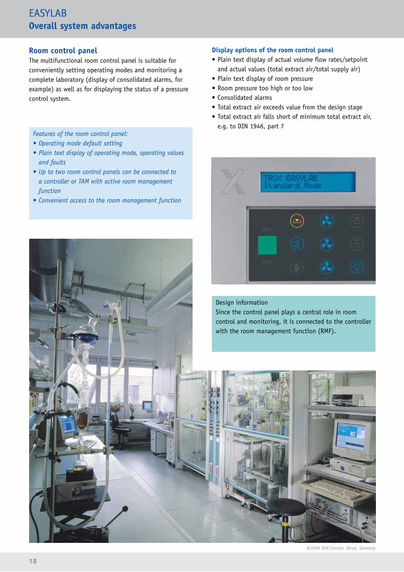
Room control panelThe multifunctional room control panel is suitable for conveniently setting operating modes and monitoring a complete laboratory (display of consolidated alarms, for example) as well as for displaying the status of a pressure control system.
Features of the room control panel:• Operating mode default setting• Plain text display of operating mode, operating values
and faults• Up to two room control panels can be connected to
a controller or TAM with active room management function
• Convenient access to the room management function
Display options of the room control panel• Plain text display of actual volume flow rates/setpoint
and actual values (total extract air/total supply air) • Plain text display of room pressure• Room pressure too high or too low• Consolidated alarms• Total extract air exceeds value from the design stage• Total extract air falls short of minimum total extract air,
e.g. to DIN 1946, part 7
ALTANA BYK-Chemie, Wesel, Germany
Design informationSince the control panel plays a central role in room control and monitoring, it is connected to the controller with the room management function (RMF).
19
EASYLABOverall system advantages
Bayer HealthCare AG,Wuppertal, Germany
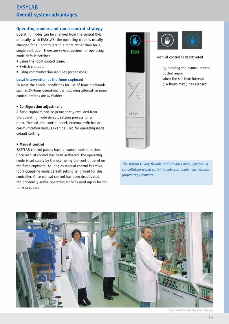
Operating modes and room control strategyOperating modes can be changed from the central BMS or locally. With EASYLAB, the operating mode is usually changed for all controllers in a room rather than for a single controller. There are several options for operating mode default setting:• using the room control panel• Switch contacts• using communication modules (expansions)
Local intervention at the fume cupboardTo meet the special conditions for use of fume cupboards, such as 24-hour operation, the following alternative room control options are available:
• Configuration adjustmentA fume cupboard can be permanently excluded from the operating mode default setting process for a room. Instead, the control panel, external switches or communication modules can be used for operating mode default setting.
• Manual controlEASYLAB control panels have a manual control button. Once manual control has been activated, the operating mode is set solely by the user using the control panel on the fume cupboard. As long as manual control is active, room operating mode default setting is ignored for this controller. Once manual control has been deactivated, the previously active operating mode is used again for the fume cupboard.
Manual control is deactivated
–by pressing the manual control button again –when the set time interval (16 hours max.) has elapsed
The system is very flexible and provides many options. A consultation would certainly help you implement bespoke project requirements.
20
EASYLABOverall system advantages
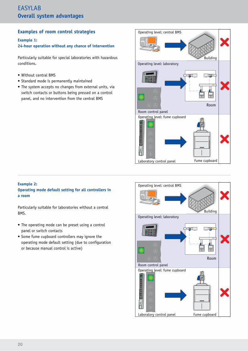
Examples of room control strategies
Example 1:24-hour operation without any chance of intervention
Particularly suitable for special laboratories with hazardous conditions.
• Without central BMS• Standard mode is permanently maintained• The system accepts no changes from external units, via
switch contacts or buttons being pressed on a control panel, and no intervention from the central BMS
Operating level: central BMS
Operating level: laboratory
Room control panel
Laboratory control panel
Operating level: fume cupboard
Building
Fume cupboard
Room
Example 2:Operating mode default setting for all controllers in a room
Particularly suitable for laboratories without a central BMS.
• The operating mode can be preset using a control panel or switch contacts
• Some fume cupboard controllers may ignore the operating mode default setting (due to configuration or because manual control is active)
Operating level: central BMS
Operating level: laboratory
Room control panel
Laboratory control panel
Operating level: fume cupboard
Building
Fume cupboard
Room
21
EASYLABOverall system advantages
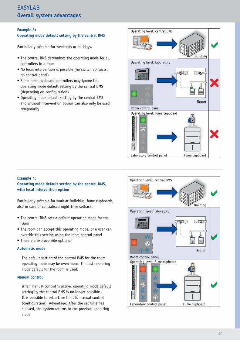
Example 3:Operating mode default setting by the central BMS
Particularly suitable for weekends or holidays.
• The central BMS determines the operating mode for all controllers in a room
• No local intervention is possible (no switch contacts, no control panel)
• Some fume cupboard controllers may ignore the operating mode default setting by the central BMS (depending on configuration)
• Operating mode default setting by the central BMS and without intervention option can also only be used temporarily
Example 4:Operating mode default setting by the central BMS, with local intervention option
Particularly suitable for work at individual fume cupboards, also in case of centralised night-time setback.
• The central BMS sets a default operating mode for the room
• The room can accept this operating mode, or a user can override this setting using the room control panel
• There are two override options:
Automatic mode
The default setting of the central BMS for the room operating mode may be overridden. The last operating mode default for the room is used.
Manual control
When manual control is active, operating mode default setting by the central BMS is no longer possible. It is possible to set a time limit fo manual control (configuration). Advantage: After the set time has elapsed, the system returns to the previous operating mode.
Operating level: central BMS
Operating level: laboratory
Room control panel
Laboratory control panel
Operating level: fume cupboard
Building
Fume cupboard
Room
Operating level: central BMS
Operating level: laboratory
Room control panel
Laboratory control panel
Operating level: fume cupboard
Building
Fume cupboard
Room
22
EASYLABOverall system advantages
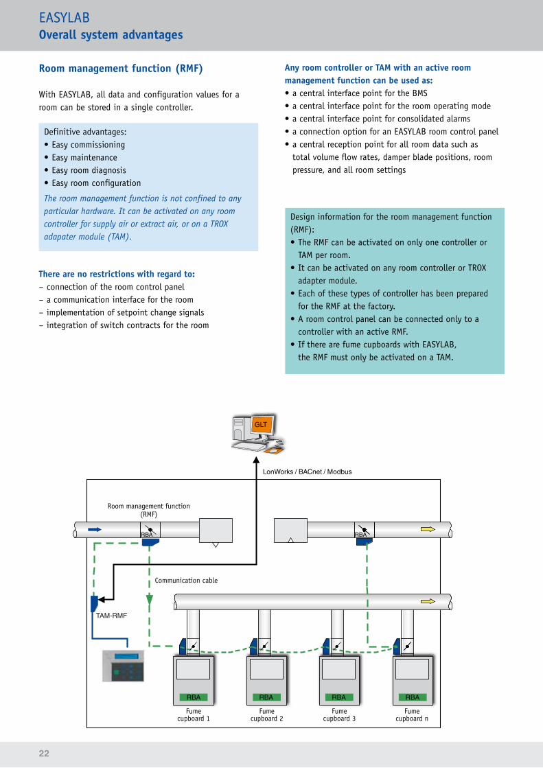
Room management function (RMF)
With EASYLAB, all data and configuration values for a room can be stored in a single controller.
Definitive advantages:• Easy commissioning• Easy maintenance• Easy room diagnosis• Easy room configuration
The room management function is not confined to any particular hardware. It can be activated on any room controller for supply air or extract air, or on a TROX adapater module (TAM).
There are no restrictions with regard to: – connection of the room control panel – a communication interface for the room – implementation of setpoint change signals – integration of switch contracts for the room
Any room controller or TAM with an active room management function can be used as:• a central interface point for the BMS• a central interface point for the room operating mode• a central interface point for consolidated alarms• a connection option for an EASYLAB room control panel• a central reception point for all room data such as
total volume flow rates, damper blade positions, room pressure, and all room settings
Design information for the room management function (RMF):• The RMF can be activated on only one controller or
TAM per room.• It can be activated on any room controller or TROX
adapter module.• Each of these types of controller has been prepared
for the RMF at the factory.• A room control panel can be connected only to a
controller with an active RMF.• If there are fume cupboards with EASYLAB,
the RMF must only be activated on a TAM.
TAM-RMF
GLT
RBA
RBA RBA
RBA RBA RBA
LonWorks / BACnet / Modbus
Fume cupboard 1
Room management function(RMF)
Fume cupboard 2
Fume cupboard 3
Fume cupboard n
Communication cable
23
EASYLABOverall system advantages
Interface to the central BMS
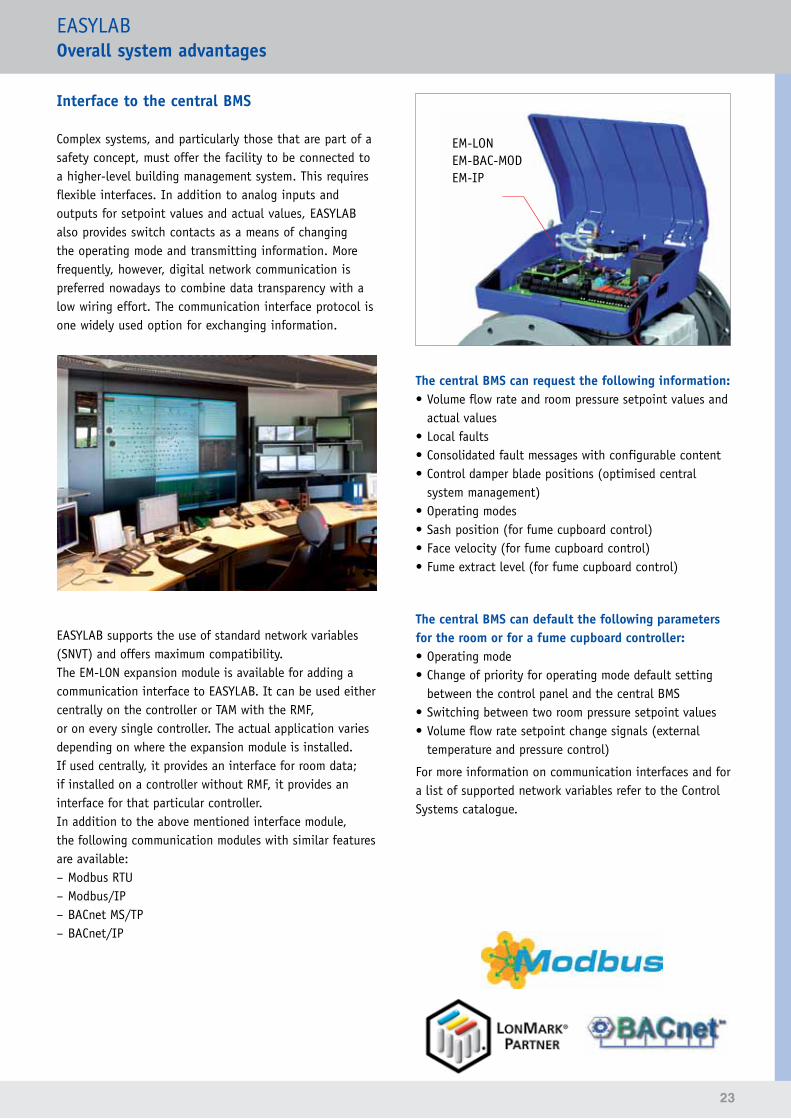
Complex systems, and particularly those that are part of a safety concept, must offer the facility to be connected to a higher-level building management system. This requires flexible interfaces. In addition to analog inputs and outputs for setpoint values and actual values, EASYLAB also provides switch contacts as a means of changing the operating mode and transmitting information. More frequently, however, digital network communication is preferred nowadays to combine data transparency with a low wiring effort. The communication interface protocol is one widely used option for exchanging information.
EASYLAB supports the use of standard network variables (SNVT) and offers maximum compatibility.The EM-LON expansion module is available for adding a communication interface to EASYLAB. It can be used either centrally on the controller or TAM with the RMF, or on every single controller. The actual application varies depending on where the expansion module is installed. If used centrally, it provides an interface for room data; if installed on a controller without RMF, it provides an interface for that particular controller.In addition to the above mentioned interface module, the following communication modules with similar features are available: – Modbus RTU – Modbus/IP – BACnet MS/TP – BACnet/IP
EM-LONEM-BAC-MODEM-IP
The central BMS can request the following information:• Volume flow rate and room pressure setpoint values and
actual values• Local faults• Consolidated fault messages with configurable content• Control damper blade positions (optimised central
system management)• Operating modes• Sash position (for fume cupboard control)• Face velocity (for fume cupboard control)• Fume extract level (for fume cupboard control)
The central BMS can default the following parameters for the room or for a fume cupboard controller:• Operating mode• Change of priority for operating mode default setting
between the control panel and the central BMS• Switching between two room pressure setpoint values• Volume flow rate setpoint change signals (external
temperature and pressure control)
For more information on communication interfaces and for a list of supported network variables refer to the Control Systems catalogue.
24
EASYLABCommissioning
One of the main development goals for EASYLAB was simple commissioning. Due to the new communication system, installation and commissioning require much less time and effort than with previously used systems.
Commissioning without network management toolOnce the components have been connected via the plug-in communication cable and power is supplied, the controllers in a room and the TAM communicate and exchange data automatically. It is not necessary to define communication paths or data points. The use of a network management tool such as Echelon LonMaker is required only for a communications interface to the central BMS.
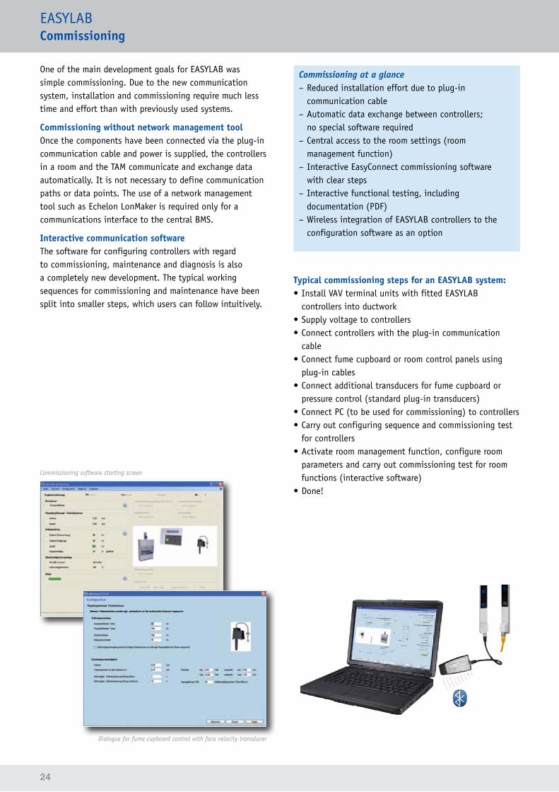
Interactive communication softwareThe software for configuring controllers with regard to commissioning, maintenance and diagnosis is also a completely new development. The typical working sequences for commissioning and maintenance have been split into smaller steps, which users can follow intuitively.
Commissioning software starting screen
Dialogue for fume cupboard control with face velocity transducer
Commissioning at a glance – Reduced installation effort due to plug-in communication cable
– Automatic data exchange between controllers; no special software required
– Central access to the room settings (room management function)
– Interactive EasyConnect commissioning software with clear steps
– Interactive functional testing, including documentation (PDF)
– Wireless integration of EASYLAB controllers to the configuration software as an option
Typical commissioning steps for an EASYLAB system:• Install VAV terminal units with fitted EASYLAB
controllers into ductwork• Supply voltage to controllers• Connect controllers with the plug-in communication
cable• Connect fume cupboard or room control panels using
plug-in cables• Connect additional transducers for fume cupboard or
pressure control (standard plug-in transducers)• Connect PC (to be used for commissioning) to controllers• Carry out configuring sequence and commissioning test
for controllers• Activate room management function, configure room
parameters and carry out commissioning test for room functions (interactive software)
• Done!
25
EASYLABDesign basics
Electrical system setup• 24 V AC power supply; 230 V AC as an option with
EM-TRF or EM-TRF-USV expansion module• Connection of up to 24 VAV terminal units with
EASYLAB TCU3 controllers using the plug-in communication cable
• Any combination of EASYLAB TCU3 controllers within a system:Fume cupboard controller, supply air controller, extract air controller, TROX adapter module TAM
• Connection via communication cable – Plug-in standard network cables (patch cables) type S-FTP (connecting sockets at the outside)
– Alternatively: network cable type S-FTP without plugs to be connected to terminals on the inside
• Linear connection of the controllers• Termination of the communication cable (both ends)
using the integral terminal resistors of the controller (can be activated individually)
• Total length of the communication cable for an EASYLAB room: up to 300 m
Centralised system setupFor a clear overview of the room settings, one controller (supply air controller, extract air controller or TAM) can be selected to assume the room management function: If there are fume cupboards with EASYLAB, the RMF must only be activated on a TAM. • Activation of the room management function (RMF) on
one controller (supply air, extract air, TAM)• Controller with active room management function as
central interface for room default settings or room values (ideally via service socket on the control panel)
• Settings such as the minimum extract air, air transfer or constant volume flow rates are stored here and automatically used by the entire system
• Centralised installation of the room interface via switching contacts, analog signals and communcation modules
• Connection of the room control panel to the controller with active RMF
Control panels• For fume cupboards: Choice of BE-SEG-02 or BE-LCD-01• For rooms: Only BE-LCD-01 on the controller with the
RMF• Up to two control panels can be connected• A 5 m plug-in connecting cable for the control panel is
provided• Alternatively, standard network cables type S-FTP of up
to 40 m can be used
Addition of external volume flow rate values
Additional Existing inputs on controller forFume cupboard Supply air
Extract airTAM Supply air / Extract air / TAM
with room management function
Variable extract or supply air via 0–10 V DC Up to 41 4 5 2-42
Constant extract or supply air via switch contacts Up to 52 6 6 Up to 62
1 According to the control strategy2 Depending on the number of special functions, which may also use some of the 6 switch contacts
Interface to central BMS
Option Fume cupboard Supply air / Extract air / TAM Supply air / Extract air / TAMwith room management function
Alarms sent from volt-free switch contacts (outputs) 1 1 2
Room operating mode default settings via switch contacts (inputs)
– – •
Controller actual volume flow rates sent via 0–10 V analog outputs
Controller actual volume flow rate, total volume flow rate for the room, damper blade position
Controller interface, actual values and alarms with expansion module 1 •1 •1 •1
Room interface, cumulative values and alarms with expansion module 1
– – •1
1 Only with expansion module EM-LON, EM-BAC-MOD or EM-IP
26
27
EASYLABFume cupboard control
Fume cupboards have a special function when it comes to protecting the staff in a lab. Three prime objectives are obvious:
1. RetentionFume cupboards must prevent dangerous concentrations of gases, fumes or dusts from escaping the fume cupboard and being released into the lab.
2. Air changeFume cupboards must prevent the development of an atmosphere that can ignite or even explode.
3. Splash and shatter protectionFume cupboards must prevent spray or flying fragments from injuring people.
While splash and shatter protection is obviously ensured by the construction of a fume cupboard, the first two points require volume flow control. EASYLAB covers all the usual control options and meets, hence, all individual requirements.
All LABCONTROL controllers and hence also the EASYLAB TCU3 controller are tested to EN 14175, part 6, by an independent, certified testing institute.
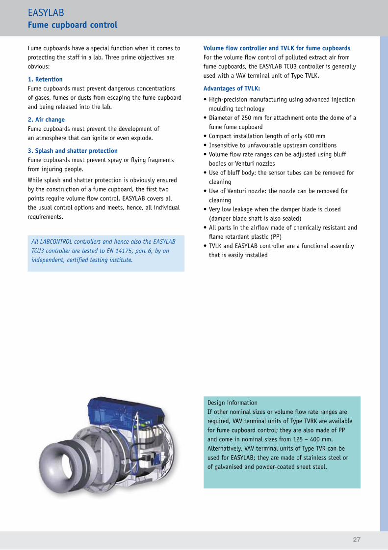
Volume flow controller and TVLK for fume cupboardsFor the volume flow control of polluted extract air from fume cupboards, the EASYLAB TCU3 controller is generally used with a VAV terminal unit of Type TVLK.
Advantages of TVLK:
• High-precision manufacturing using advanced injection moulding technology
• Diameter of 250 mm for attachment onto the dome of a fume fume cupboard
• Compact installation length of only 400 mm• Insensitive to unfavourable upstream conditions• Volume flow rate ranges can be adjusted using bluff
bodies or Venturi nozzles• Use of bluff body: the sensor tubes can be removed for
cleaning• Use of Venturi nozzle: the nozzle can be removed for
cleaning• Very low leakage when the damper blade is closed
(damper blade shaft is also sealed)• All parts in the airflow made of chemically resistant and
flame retardant plastic (PP)• TVLK and EASYLAB controller are a functional assembly
that is easily installed
Design informationIf other nominal sizes or volume flow rate ranges are required, VAV terminal units of Type TVRK are available for fume cupboard control; they are also made of PP and come in nominal sizes from 125 – 400 mm. Alternatively, VAV terminal units of Type TVR can be used for EASYLAB; they are made of stainless steel or of galvanised and powder-coated sheet steel.
28
EASYLABFume cupboard control
Strategies for fume cupboard controlThere are two types of control strategies: standard mode ('lab mode') and special operating modes.
Standard modeThe standard mode for fume cupboard control allows for different recording systems that support various control strategies. – Constant value control – Two-point or three-point control via switch contacts – Variable volume flow rate control based on sash distance (with sash distance sensor)
– Variable volume flow rate control based on face velocity (with face velocity transducer)
Special operating modesFor certain operating situations, special operating modes are available that can be activated by means of operating mode default settings, either from the central BMS or by a user using the fume cupboard control panel.The following special operating modes are available in addition to the standard mode: – Increased operation, e.g. in an emergency – Reduced operation, e.g. as night-time setback – Shut-off mode, e.g. for system shutdown – OPEN mode (damper blades are open, cannot be activated using a control panel; external default setting only)
Standard mode – adjusting volume flow rates to up to three values of different levels
Constant value controlConstant value control is the simplest option; it means that a constant setpoint is maintained. The control system reacts to duct pressure fluctuations and corrects the volume flow rate accordingly, quickly and precisely.
Duct pressure
Design informationConstant value control causes the highest energy costs.
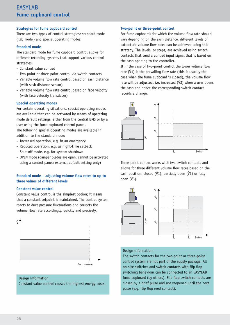
Two-point or three-point controlFor fume cupboards for which the volume flow rate should vary depending on the sash distance, different levels of extract air volume flow rates can be achieved using this strategy. The levels, or steps, are achieved using switch contacts that send a control input signal that is based on the sash opening to the controller.If in the case of two-point control the lower volume flow rate (1) is the prevailing flow rate (this is usually the case when the fume cupboard is closed), the volume flow rate will be adjusted, i.e. increased (2) when a user opens the sash and hence the corresponding switch contact records a change.
S1
2
1
S1 Switch
Three-point control works with two switch contacts and allows for three different volume flow rates based on the sash position: closed (1), partially open (2) or fully open (3).
3
2
1
S1 S2 Switch
S1
S2
Design informationThe switch contacts for the two-point or three-point control system are not part of the supply package. All on-site switches and switch contacts with flip flop switching behaviour can be connected to an EASYLAB fume cupboard (by others). Flip flop switch contacts are closed by a brief pulse and not reopened until the next pulse (e.g. flip flop reed contact).
29
EASYLABFume cupboard control
Standard mode – variable adjustment of volume flow rates to the operating situation
From the point of view of energy savings and safety, a variable control system is the most convenient way to control a fume cupboard.
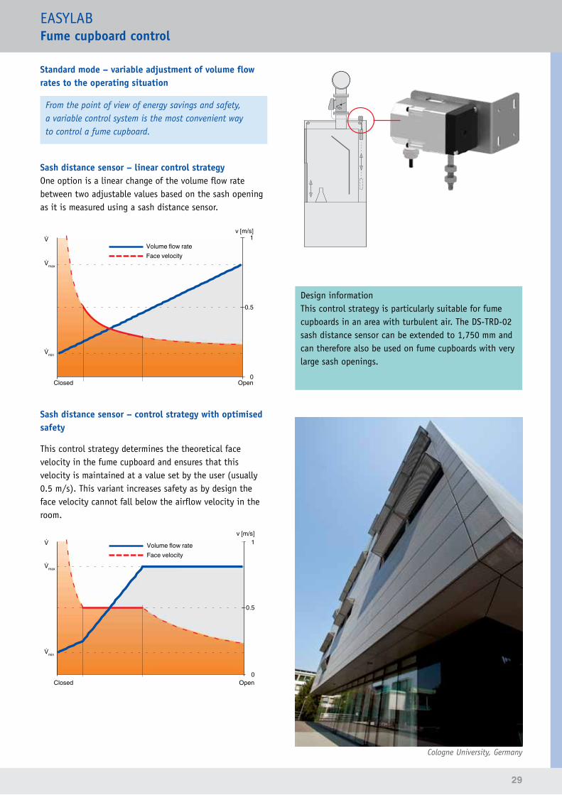
Sash distance sensor – linear control strategyOne option is a linear change of the volume flow rate between two adjustable values based on the sash opening as it is measured using a sash distance sensor.
min
max
Closed Open
Volume flow rateFace velocity
v [m/s]1
0.5
0
Sash distance sensor – control strategy with optimised safety
This control strategy determines the theoretical face velocity in the fume cupboard and ensures that this velocity is maintained at a value set by the user (usually 0.5 m/s). This variant increases safety as by design the face velocity cannot fall below the airflow velocity in the room.
min
max
Closed Open
Volume flow rateFace velocity
v [m/s]1
0.5
0
Design informationThis control strategy is particularly suitable for fume cupboards in an area with turbulent air. The DS-TRD-02 sash distance sensor can be extended to 1,750 mm and can therefore also be used on fume cupboards with very large sash openings.
Cologne University, Germany
30
EASYLABFume cupboard control
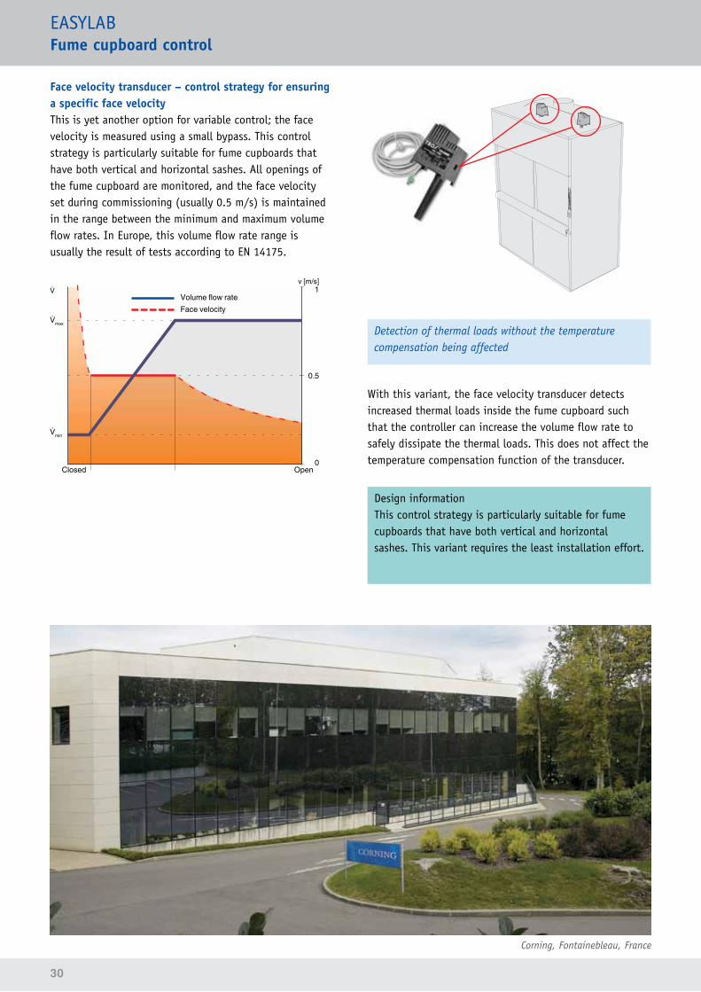
Face velocity transducer – control strategy for ensuring a specific face velocity This is yet another option for variable control; the face velocity is measured using a small bypass. This control strategy is particularly suitable for fume cupboards that have both vertical and horizontal sashes. All openings of the fume cupboard are monitored, and the face velocity set during commissioning (usually 0.5 m/s) is maintained in the range between the minimum and maximum volume flow rates. In Europe, this volume flow rate range is usually the result of tests according to EN 14175.
min
max
Closed Open
v [m/s]1
0.5
0
Volume flow rateFace velocity
Corning, Fontainebleau, France
Detection of thermal loads without the temperature compensation being affected
With this variant, the face velocity transducer detects increased thermal loads inside the fume cupboard such that the controller can increase the volume flow rate to safely dissipate the thermal loads. This does not affect the temperature compensation function of the transducer.
Design informationThis control strategy is particularly suitable for fume cupboards that have both vertical and horizontal sashes. This variant requires the least installation effort.
31
EASYLABFume cupboard control
Additional functions
Diversity controlEASYLAB supports diversity control such that the total extract air as determined in the design stage is maintained. This function ensures that the total extract air volume flow rate is not exceeded; to achieve this, the function reduces the extract air volume flow rate on some fume cupboards in order to allow for safe working conditions on as many fume cupboards in the lab as possible. If the volume flow rate for a fume cupboard is reduced, a signal to this effect is issued on the fume cupboard control panel.
Design informationDiversity control can only be used together with an EASYLAB TAM.
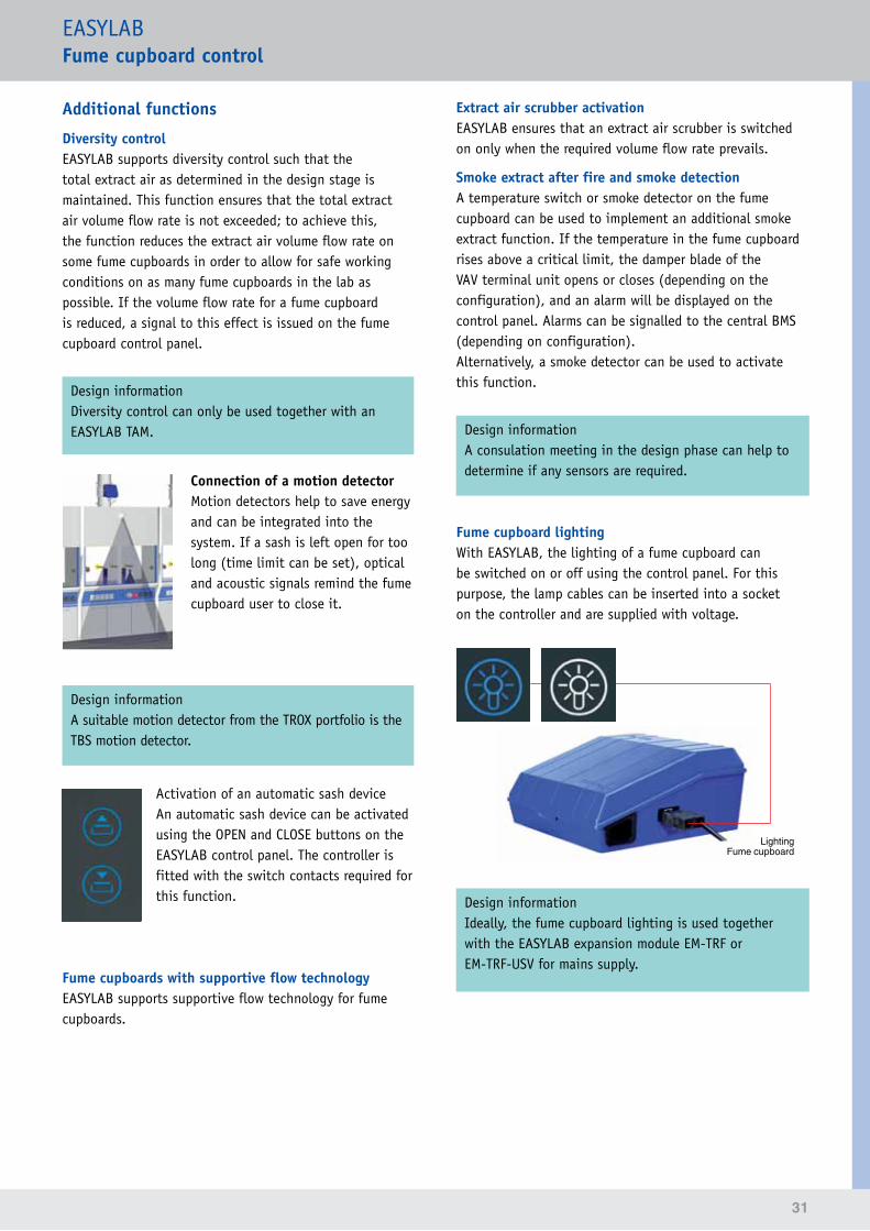
Connection of a motion detectorMotion detectors help to save energy and can be integrated into the system. If a sash is left open for too long (time limit can be set), optical and acoustic signals remind the fume cupboard user to close it.
Design informationA suitable motion detector from the TROX portfolio is the TBS motion detector.
Activation of an automatic sash deviceAn automatic sash device can be activated using the OPEN and CLOSE buttons on the EASYLAB control panel. The controller is fitted with the switch contacts required for this function.
Fume cupboards with supportive flow technologyEASYLAB supports supportive flow technology for fume cupboards.
Extract air scrubber activationEASYLAB ensures that an extract air scrubber is switched on only when the required volume flow rate prevails.
Smoke extract after fire and smoke detectionA temperature switch or smoke detector on the fume cupboard can be used to implement an additional smoke extract function. If the temperature in the fume cupboard rises above a critical limit, the damper blade of the VAV terminal unit opens or closes (depending on the configuration), and an alarm will be displayed on the control panel. Alarms can be signalled to the central BMS (depending on configuration).Alternatively, a smoke detector can be used to activate this function.
Design informationA consulation meeting in the design phase can help to determine if any sensors are required.
Fume cupboard lightingWith EASYLAB, the lighting of a fume cupboard can be switched on or off using the control panel. For this purpose, the lamp cables can be inserted into a socket on the controller and are supplied with voltage.
LightingFume cupboard
Design informationIdeally, the fume cupboard lighting is used together with the EASYLAB expansion module EM-TRF or EM-TRF-USV for mains supply.
32
EASYLABFume cupboard control
Addition of variable volume flow ratesVolume flow controllers with an analog actual value output (0–10 V DC), such as those for hoods or extractor arms, can be integrated with the fume cupboard. Depending on the configuration, the flow rates are interpreted as extract air or supply air and included in the total extract air volume flow rate or the total supply air volume flow rate.
Design information• Each fume cupboard is provided with three analog
inputs.• Additional values can be signalled to a TROX adapter
module (TAM).
Addition of constant volume flow ratesConstant volume flow rates can be signalled to the fume cupboard controller using switch contacts. Depending on the configuration, the flow rates are interpreted as extract air or supply air and included in the total extract air volume flow rate or the total supply air volume flow rate.
Design information• Depending on the number of special functions used,
up to five switched inputs are available on each fume cupboard controller.
• Additional values can be signalled to a TROX adapter module (TAM).
Input signals Analog input Digital input Communication modulesAddition of variable extract or supply air volume flow rates •Addition of constant extract or supply air volume flow rates (can be switched) •
Special functions: request of extract air scrubber, supportive flow technology feedback, smoke extract, motion detector •
Operating mode default setting (only for individual operating mode default setting) • •
Output signals Analog input Digital input Communication modulesActual volume flow rate of the fume cupboard • •Total extract air or total supply air volume flow rate • •Face velocity / Sash position •Alarm signalling • •Damper blade position • •Operating mode •Special functions: activation of extract air scrubber, control input signal for supportive flow technology, control input signal for automatic sash device, fume cupboard lighting
• •
Input and output signals on the fume cupboard controller
33
EASYLABFume cupboard control
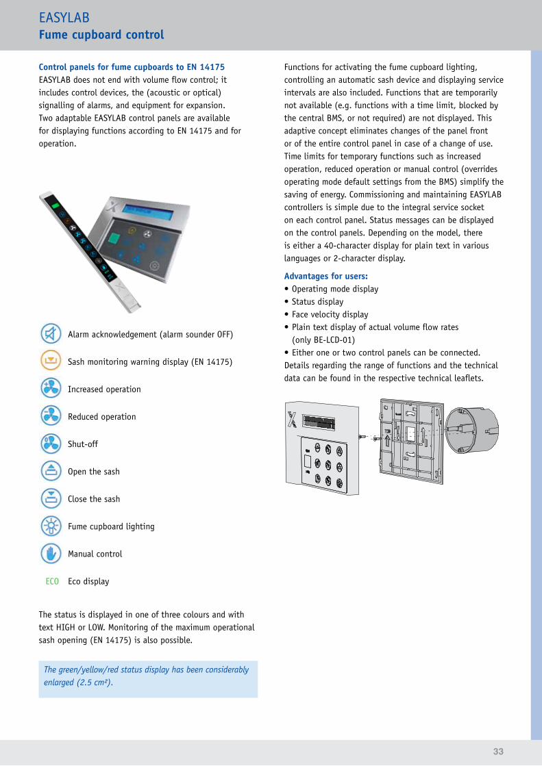
ControlpanelsforfumecupboardstoEN 14175EASYLAB does not end with volume flow control; it includes control devices, the (acoustic or optical) signalling of alarms, and equipment for expansion.Two adaptable EASYLAB control panels are available for displaying functions according to EN 14175 and for operation.
Alarm acknowledgement (alarm sounder OFF)
Sash monitoring warning display (EN 14175)
Increased operation
Reduced operation
Shut-off
Open the sash
Close the sash
Fume cupboard lighting
Manual control
ECO Eco display
The status is displayed in one of three colours and with text HIGH or LOW. Monitoring of the maximum operational sash opening (EN 14175) is also possible.
The green/yellow/red status display has been considerably enlarged (2.5 cm²).
Functions for activating the fume cupboard lighting, controlling an automatic sash device and displaying service intervals are also included. Functions that are temporarily not available (e.g. functions with a time limit, blocked by the central BMS, or not required) are not displayed. This adaptive concept eliminates changes of the panel front or of the entire control panel in case of a change of use.Time limits for temporary functions such as increased operation, reduced operation or manual control (overrides operating mode default settings from the BMS) simplify the saving of energy. Commissioning and maintaining EASYLAB controllers is simple due to the integral service socket on each control panel. Status messages can be displayed on the control panels. Depending on the model, there is either a 40-character display for plain text in various languages or 2-character display.
Advantages for users:• Operating mode display• Status display• Face velocity display• Plain text display of actual volume flow rates
(only BE-LCD-01)• Either one or two control panels can be connected.Details regarding the range of functions and the technical data can be found in the respective technical leaflets.
34
35
EASYLABFumecupboardcontrol•applicationexamples
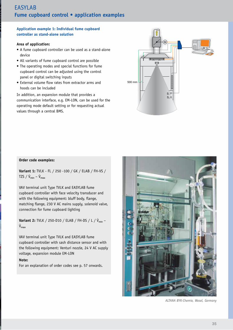
Application example 1: Individual fume cupboard controller as stand-alone solution
Area of application:• A fume cupboard controller can be used as a stand-alone
device• All variants of fume cupboard control are possible• The operating modes and special functions for fume
cupboard control can be adjusted using the control panel or digital switching inputs
• External volume flow rates from extractor arms and hoods can be included
In addition, an expansion module that provides a communication interface, e.g. EM-LON, can be used for the operating mode default setting or for requesting actual values through a central BMS.
Order code examples:
Variant 1: TVLK - FL / 250 -100 / GK / ELAB / FH-VS / TZS / min – mₐₓ
VAV terminal unit Type TVLK and EASYLAB fume cupboard controller with face velocity transducer and with the following equipment: bluff body, flange, matching flange, 230 V AC mains supply, solenoid valve, connection for fume cupboard lighting
Variant 2: TVLK / 250-D10 / ELAB / FH-DS / L / min – mₐₓ
VAV terminal unit Type TVLK and EASYLAB fume cupboard controller with sash distance sensor and with the following equipment: Venturi nozzle, 24 V AC supply voltage, expansion module EM-LON
Note:For an explanation of order codes see p. 57 onwards.
ALTANA BYK-Chemie, Wesel, Germany
36
EASYLABFumecupboardcontrol•applicationexamples
Application example 2: Several fume cupboard controllers with TROX adapter module TAM as the central interface point
Area of application:Fume cupboard controllers are supplied by the laboratory furniture manufacturer• Central interface point, e.g. to the central BMS or for
connecting supply air and/or extract air controllers• All variants of fume cupboard control are possible• The operating modes and special functions for fume
cupboard control can be adjusted using the control panel.
• Room operating modes can be signalled to the TROX adapter module TAM.
• External volume flow rates from extractor arms and hoods can be included (signalling)
System setup:All fume cupboard controllers are interconnected with the plug-in communication cable. An additional TROX adapter module TAM is integrated at any point. This module stores the volume flow rates of all controllers in the system and can signal the total volume flow rates to a room controller or to the central BMS, e.g. via analog signals or a communication interface. Up to 23 fume cupboard controllers can be connected to a TAM. Fume cupboards and the supply air controller allow for signalling additional volume flow rates using 0 – 10 V signals or switch contacts.
Advantages of the TROX adapter module (TAM) with room management function:If the room management function is active on the TROX adapter module, the centralised signalling of an operating mode default with a room control panel is possible. All controllers connected through the communication cable follow this central default setting unless it has been set in the controller that this room default setting should not apply. This can be important if individual fume cupboards are used for 24-hour operation.
Additional options of the RMF:• Volume flow rate balancing• Display of room functions on the room control panel• Consolidated alarms
Integration with the central BMS:For integration using a communication interface, the EM-LON expansion module may be used as follows:• On a fume cupboard controller
→ Local data interface for a fume cupboard• On the TROX adapter module TAM
→ Central data interface for the roomOperating mode defaults, actual volume flow rate values and consolidated alarms can be exchanged through the network. This reduces the required data points and hence the costs. The TAM becomes the main communication interface in the laboratory.
Central BMS
Communication interfacee.g. damper blade position, alarm signal, operating mode default settings, feedback
Analog 0–10 V DCe.g. total extract air
Switch contactse.g. operating mode default
setting,alarms
Communication cable
TROX adapter mo-dule (TAM)
Fume cupboard
1
Fume cupboard
3
Fume cupboard
n
Fume cupboard
2
37
EASYLABFumecupboardcontrol•applicationexamples
Order code examples:
Fume cupboard controller:TVLK / 250-100 / ELAB / FH-VS / Z / min – mₐₓVAV terminal unit Type TVLK and fume cupboard controller with face velocity transducer and with the following equipment: bluff body, solenoid valve, 24 V AC supply voltage
TROX adapter moduleTAM / TM / LAB-RMFTROX adapter module with the following equipment:230 V AC mains supply, expansion module EM-BAC-MOD (Modbus), room management function for laboratories
Note:For an explanation of order codes see p. 57 onwards.
Design informationThe following options are available only when the complete EASYLAB solution (only EASYLAB controllers) is installed:• Easy integration of room controllers using a standard
communication cable• Automatic volume flow rate balancing including all
supply air and extract air controllers• Monitoring of the total extract air volume defined
during the design phase; diversity control as correction option
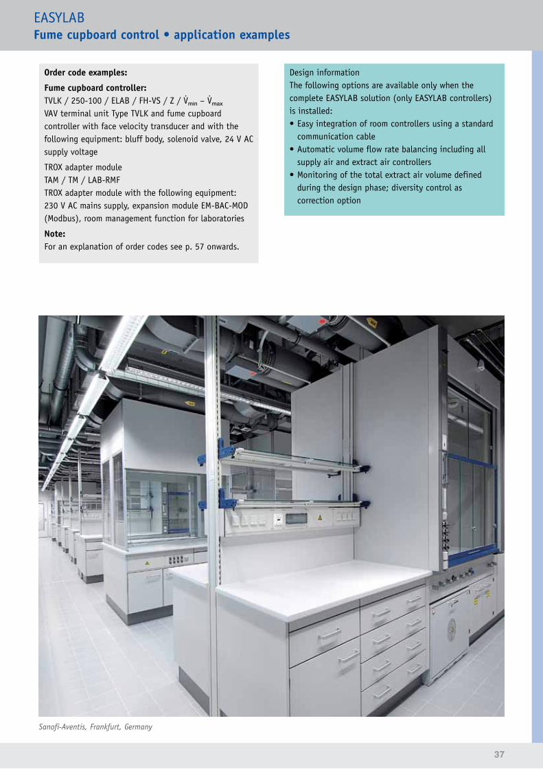
Sanofi-Aventis, Frankfurt, Germany
38
EASYLABEquipment functions
Control strategy for supply air and extract air
Areas of applicationThe EASYLAB volume flow controllers for supply and extract air can be integrated with the plug and play communication system. They are used to integrate additional options such as extractor arms, machinery or ovens.
There are several principal control strategies: standard mode with variable volume flow rate default setting using a DC signal, with two or three volume flow rate ranges, or with a constant setpoint value. In addition, there are special operating modes such as increased operation, reduced operation, shut-of, and OPEN mode.
All known expansion modules such as EM-AUTOZERO, EM-TRF, EM-TRF-USV and communication modules can be easily connected.
Standard modeIn supply air or extract air standard mode, options include variable control using a DC signal, control with two or three switching steps for predefined volume flow rate ranges, or control using a constant setpoint value.
Special operating modesSpecial operating modes such as increased or reduced operation, shut-off, or OPEN mode are also possible. This controller variant can hence be integrated with the EASYLAB operating mode system.
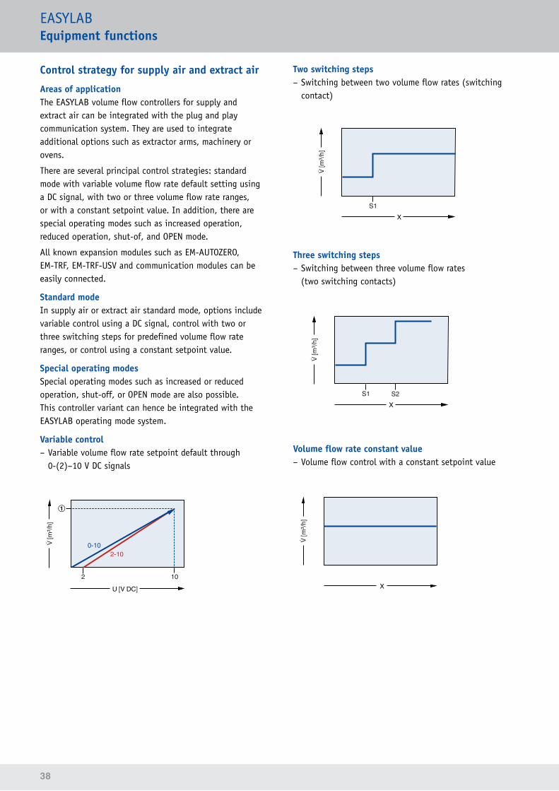
Variable control – Variable volume flow rate setpoint default through 0-(2)–10 V DC signals
①
2 10
2-100-10
U [V DC]
[m
�/h]
Two switching steps – Switching between two volume flow rates (switching contact)
X
[m
�/h]
S1
Three switching steps – Switching between three volume flow rates (two switching contacts)
X
[m
�/h]
S1 S2
Volume flow rate constant value – Volume flow control with a constant setpoint value
X
[m
�/h]
39
EASYLABRoom control
For the volume flow rate control in a room, the EASYLAB TCU3 controllers can be combined with all TROX VAV terminal units of Types TVR·TVRK·TVZ·TVA·TVJ·TVT·TZ-Silenzio and TA-Silenzio. These include units made of galvanised sheet steel, powder-coated units, and stainless steel and plastic (PP) constructions. All controllers for a room (up to 24) are interconnected with a plug-in communication cable.
Advantages of EASYLAB room controllers• Easy integration of room controllers using a standard
communication cable• Flow rate balancing with defined air transfer• Automatic volume flow rate balancing including all
supply air and extract air controllers• Diversity control• Optimised extract air balancing• The minimum discharge velocity on air terminal devices
is maintained• Critical control situations are safe due to an
uninterruptible power supply unit
New:If more than one supply or extract air controller is used in a room, the volume flow rates are distributed automatically.
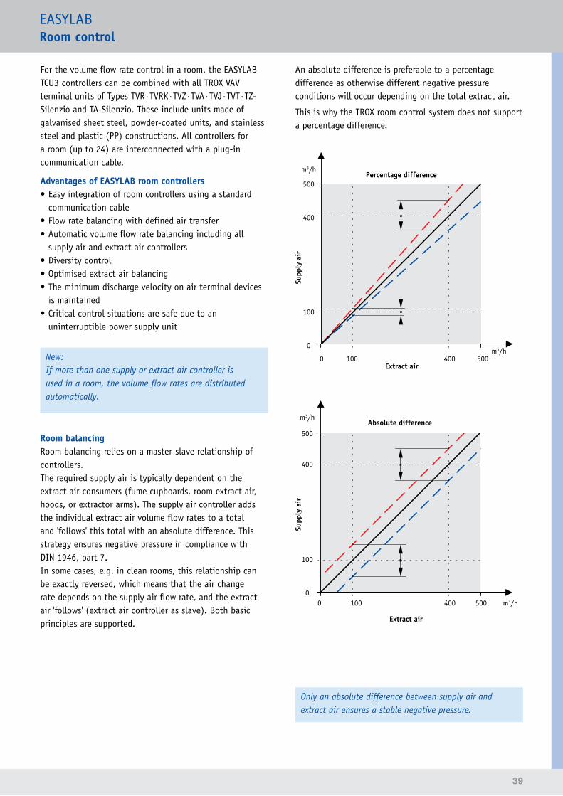
Room balancingRoom balancing relies on a master-slave relationship of controllers.The required supply air is typically dependent on the extract air consumers (fume cupboards, room extract air, hoods, or extractor arms). The supply air controller adds the individual extract air volume flow rates to a total and 'follows' this total with an absolute difference. This strategy ensures negative pressure in compliance with DIN 1946, part 7.In some cases, e.g. in clean rooms, this relationship can be exactly reversed, which means that the air change rate depends on the supply air flow rate, and the extract air 'follows' (extract air controller as slave). Both basic principles are supported.
An absolute difference is preferable to a percentage difference as otherwise different negative pressure conditions will occur depending on the total extract air.
This is why the TROX room control system does not support a percentage difference.
m3/h
500
400
100
0
Supp
ly a
ir
Percentage difference
m3/h0 100 400 500
Extract air
m3/h
500
400
100
0 0 100 400 500 m3/h
Extract air
Supp
ly a
ir
Absolute difference
Only an absolute difference between supply air and extract air ensures a stable negative pressure.
40
EASYLABRoom control
Additional room control functions
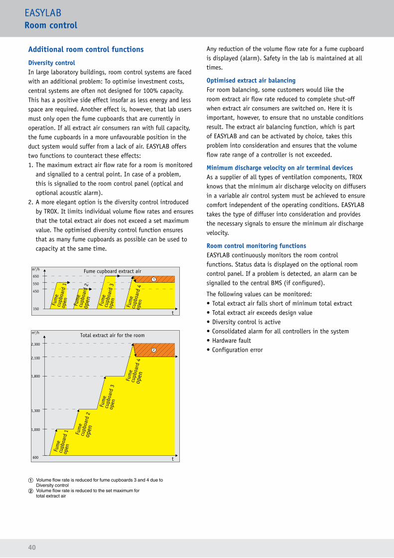
Diversity controlIn large laboratory buildings, room control systems are faced with an additional problem: To optimise investment costs, central systems are often not designed for 100% capacity. This has a positive side effect insofar as less energy and less space are required. Another effect is, however, that lab users must only open the fume cupboards that are currently in operation. If all extract air consumers ran with full capacity, the fume cupboards in a more unfavourable position in the duct system would suffer from a lack of air. EASYLAB offers two functions to counteract these effects:1. The maximum extract air flow rate for a room is monitored
and signalled to a central point. In case of a problem, this is signalled to the room control panel (optical and optional acoustic alarm).
2. A more elegant option is the diversity control introduced by TROX. It limits individual volume flow rates and ensures that the total extract air does not exceed a set maximum value. The optimised diversity control function ensures that as many fume cupboards as possible can be used to capacity at the same time.
1
m3/h
650
550
450
150
m3/h
2,300
2,100
1,800
1,300
1,000
600
Fum
e cu
pboa
rd 1
op
en Fum
e cu
pboa
rd 3
op
en
Fum
e cu
pboa
rd 4
op
enFum
e cu
pboa
rd 2
open
t
t
Fume cupboard extract air
Total extract air for the room
Fum
e cu
pboa
rd 1
op
en
Fum
e cu
pboa
rd 3
op
en
Fum
e cu
pboa
rd 4
open
Fum
e cu
pboa
rd 2
open
① Volume flow rate is reduced for fume cupboards 3 and 4 due to Diversity control② Volume flow rate is reduced to the set maximum for total extract air
Any reduction of the volume flow rate for a fume cupboard is displayed (alarm). Safety in the lab is maintained at all times.
Optimised extract air balancingFor room balancing, some customers would like the room extract air flow rate reduced to complete shut-off when extract air consumers are switched on. Here it is important, however, to ensure that no unstable conditions result. The extract air balancing function, which is part of EASYLAB and can be activated by choice, takes this problem into consideration and ensures that the volume flow rate range of a controller is not exceeded.
Minimum discharge velocity on air terminal devicesAs a supplier of all types of ventilation components, TROX knows that the minimum air discharge velocity on diffusers in a variable air control system must be achieved to ensure comfort independent of the operating conditions. EASYLAB takes the type of diffuser into consideration and provides the necessary signals to ensure the minimum air discharge velocity.
Room control monitoring functionsEASYLAB continuously monitors the room control functions. Status data is displayed on the optional room control panel. If a problem is detected, an alarm can be signalled to the central BMS (if configured).
The following values can be monitored:• Total extract air falls short of minimum total extract• Total extract air exceeds design value• Diversity control is active• Consolidated alarm for all controllers in the system• Hardware fault• Configuration error
41
EASYLABRoomcontrol•applicationexamples
Example 1: Fume cupboard controller with a supply air controller
Area of application:• Laboratory with several fume cupboards• The minimum total extract air set in the design phase is
achieved in all operating modes by the fume cupboards. No additional extract air controller is necessary
• A supply air controller supplements the supply air volume flow rate required for the operating situation
• External volume flow rates from extractor arms and hoods can be included
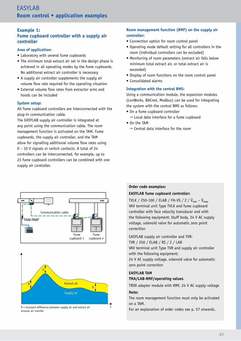
System setup:All fume cupboard controllers are interconnected with the plug-in communication cable.The EASYLAB supply air controller is integrated at any point using the communication cable. The room management function is activated on the TAM. Fume cupboards, the supply air controller, and the TAM allow for signalling additional volume flow rates using 0 – 10 V signals or switch contacts. A total of 24 controllers can be interconnected, for example, up to 23 fume cupboard controllers can be combined with one supply air controller.
Room management function (RMF) on the supply air controller:• Connection option for room control panel• Operating mode default setting for all controllers in the
room (individual controllers can be excluded)• Monitoring of room parameters (extract air falls below
minimum total extract air, or total extract air is exceeded)
• Display of room functions on the room control panel• Consolidated alarms
Integration with the central BMS:Using a communication module, the expansion modules (LonWorks, BACnet, Modbus) can be used for integrating the system with the central BMS as follows:• On a fume cupboard controller
→ Local data interface for a fume cupboard• On the TAM
→ Central data interface for the room
Order code examples:
EASYLAB fume cupboard controller:
TVLK / 250-100 / ELAB / FH-VS / Z / min – mₐₓVAV terminal unit Type TVLK and fume cupboard controller with face velocity transducer and with the following equipment: bluff body, 24 V AC supply voltage, solenoid valve for automatic zero point correction
EASYLAB supply air controller and TVR:TVR / 250 / ELAB / RS / Z / LABVAV terminal unit Type TVR and supply air controller with the following equipment:24 V AC supply voltage, solenoid valve for automatic zero point correction
EASYLAB TAM TMA/LAB-RMF/operating values
TROX adapter module with RMF, 24 V AC supply voltage
Note:The room management function must only be activated on a TAM.For an explanation of order codes see p. 57 onwards.
TAM-RMF
t
X
X
XExtract air
Supply air
X = Constant difference between supply air and extract airensures air transfer
Communication cable
Fume cupboard 1
Fume cupboard n
42
EASYLABRoomcontrol•applicationexamples
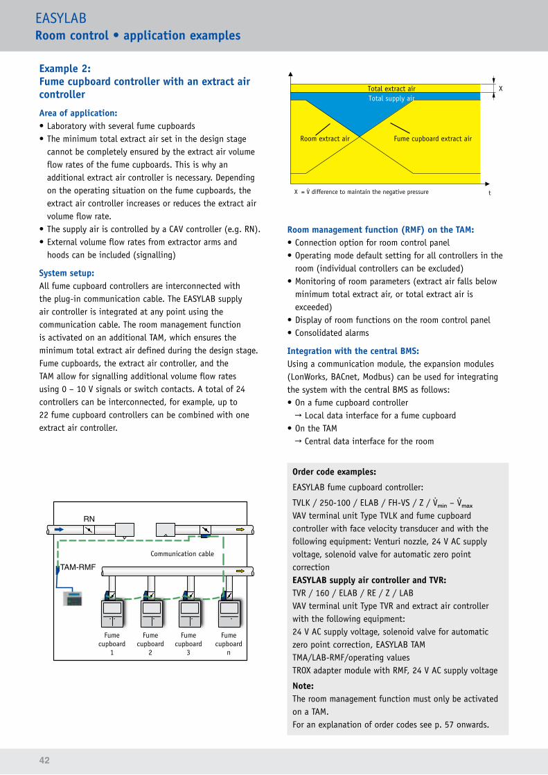
Example 2: Fume cupboard controller with an extract air controller
Area of application:• Laboratory with several fume cupboards• The minimum total extract air set in the design stage
cannot be completely ensured by the extract air volume flow rates of the fume cupboards. This is why an additional extract air controller is necessary. Depending on the operating situation on the fume cupboards, the extract air controller increases or reduces the extract air volume flow rate.
• The supply air is controlled by a CAV controller (e.g. RN).• External volume flow rates from extractor arms and
hoods can be included (signalling)
System setup:All fume cupboard controllers are interconnected with the plug-in communication cable. The EASYLAB supply air controller is integrated at any point using the communication cable. The room management function is activated on an additional TAM, which ensures the minimum total extract air defined during the design stage.Fume cupboards, the extract air controller, and the TAM allow for signalling additional volume flow rates using 0 – 10 V signals or switch contacts. A total of 24 controllers can be interconnected, for example, up to 22 fume cupboard controllers can be combined with one extract air controller.
t
Total extract airTotal supply air
Room extract air Fume cupboard extract air
X = difference to maintain the negative pressure
X
Room management function (RMF) on the TAM:• Connection option for room control panel• Operating mode default setting for all controllers in the
room (individual controllers can be excluded)• Monitoring of room parameters (extract air falls below
minimum total extract air, or total extract air is exceeded)
• Display of room functions on the room control panel• Consolidated alarms
Integration with the central BMS:Using a communication module, the expansion modules (LonWorks, BACnet, Modbus) can be used for integrating the system with the central BMS as follows:• On a fume cupboard controller
→ Local data interface for a fume cupboard• On the TAM
→ Central data interface for the room
Order code examples:
EASYLAB fume cupboard controller:
TVLK / 250-100 / ELAB / FH-VS / Z / min – mₐₓVAV terminal unit Type TVLK and fume cupboard controller with face velocity transducer and with the following equipment: Venturi nozzle, 24 V AC supply voltage, solenoid valve for automatic zero point correctionEASYLAB supply air controller and TVR:TVR / 160 / ELAB / RE / Z / LABVAV terminal unit Type TVR and extract air controller with the following equipment:24 V AC supply voltage, solenoid valve for automatic zero point correction, EASYLAB TAMTMA/LAB-RMF/operating valuesTROX adapter module with RMF, 24 V AC supply voltage
Note:The room management function must only be activated on a TAM.For an explanation of order codes see p. 57 onwards.
RN
TAM-RMFCommunication cable
Fume cupboard
1
Fume cupboard
2
Fume cupboard
3
Fume cupboard
n
43
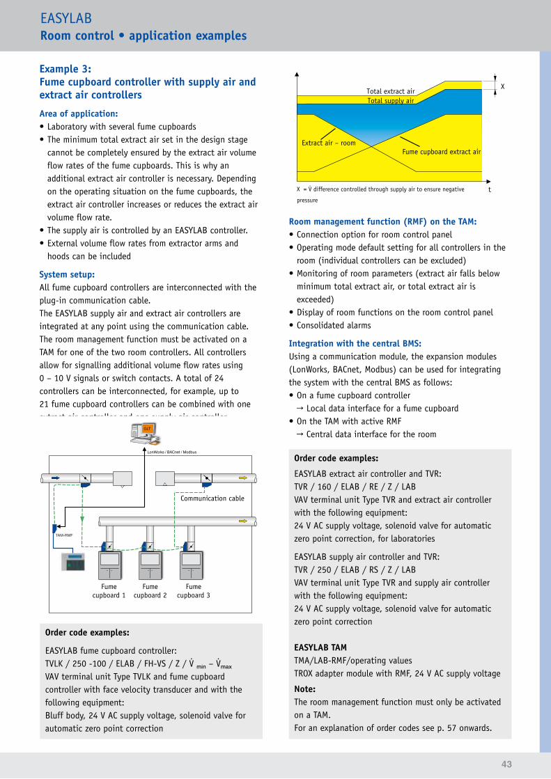
EASYLABRoomcontrol•applicationexamples
Example 3: Fume cupboard controller with supply air and extract air controllers
Area of application:• Laboratory with several fume cupboards• The minimum total extract air set in the design stage
cannot be completely ensured by the extract air volume flow rates of the fume cupboards. This is why an additional extract air controller is necessary. Depending on the operating situation on the fume cupboards, the extract air controller increases or reduces the extract air volume flow rate.
• The supply air is controlled by an EASYLAB controller.• External volume flow rates from extractor arms and
hoods can be included
System setup:All fume cupboard controllers are interconnected with the plug-in communication cable.The EASYLAB supply air and extract air controllers are integrated at any point using the communication cable. The room management function must be activated on a TAM for one of the two room controllers. All controllers allow for signalling additional volume flow rates using 0 – 10 V signals or switch contacts. A total of 24 controllers can be interconnected, for example, up to 21 fume cupboard controllers can be combined with one extract air controller and one supply air controller.
Total supply airTotal extract air
Extract air – roomFume cupboard extract air
X = difference controlled through supply air to ensure negative
pressure
X
t
Room management function (RMF) on the TAM:• Connection option for room control panel• Operating mode default setting for all controllers in the
room (individual controllers can be excluded)• Monitoring of room parameters (extract air falls below
minimum total extract air, or total extract air is exceeded)
• Display of room functions on the room control panel• Consolidated alarms
Integration with the central BMS:Using a communication module, the expansion modules (LonWorks, BACnet, Modbus) can be used for integrating the system with the central BMS as follows:• On a fume cupboard controller
→ Local data interface for a fume cupboard• On the TAM with active RMF
→ Central data interface for the room
Order code examples:
EASYLAB extract air controller and TVR:TVR / 160 / ELAB / RE / Z / LABVAV terminal unit Type TVR and extract air controller with the following equipment:24 V AC supply voltage, solenoid valve for automatic zero point correction, for laboratories
EASYLAB supply air controller and TVR:TVR / 250 / ELAB / RS / Z / LABVAV terminal unit Type TVR and supply air controller with the following equipment:24 V AC supply voltage, solenoid valve for automatic zero point correction
EASYLAB TAM TMA/LAB-RMF/operating valuesTROX adapter module with RMF, 24 V AC supply voltage
Note:The room management function must only be activated on a TAM.For an explanation of order codes see p. 57 onwards.
Order code examples:
EASYLAB fume cupboard controller:TVLK / 250 -100 / ELAB / FH-VS / Z / min – mₐₓVAV terminal unit Type TVLK and fume cupboard controller with face velocity transducer and with the following equipment:Bluff body, 24 V AC supply voltage, solenoid valve for automatic zero point correction
TAM-RMF
LonWorks / BACnet / Modbus
GLT
Communication cable
Fume cupboard 1
Fume cupboard 2
Fume cupboard 3
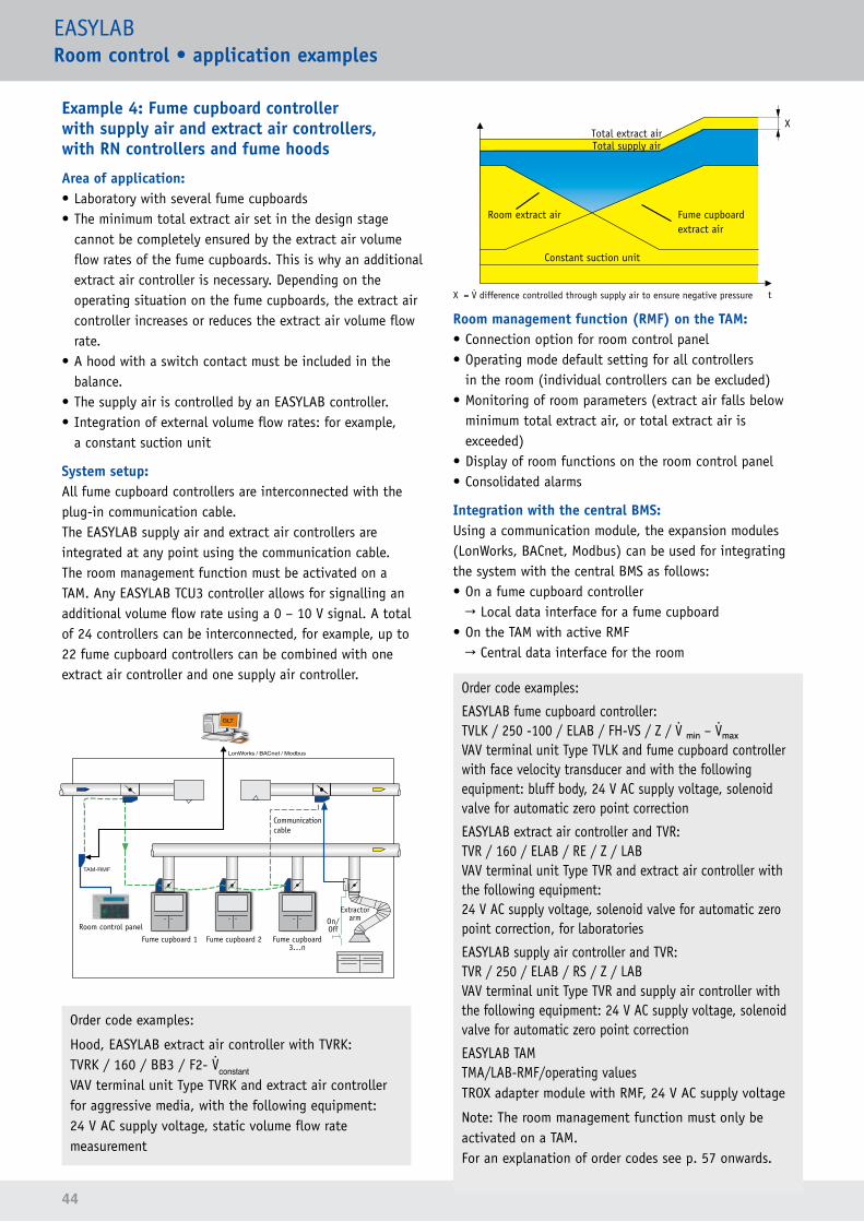
44
EASYLABRoomcontrol•applicationexamples
Example 4: Fume cupboard controller with supply air and extract air controllers, with RN controllers and fume hoods
Area of application:• Laboratory with several fume cupboards• The minimum total extract air set in the design stage
cannot be completely ensured by the extract air volume flow rates of the fume cupboards. This is why an additional extract air controller is necessary. Depending on the operating situation on the fume cupboards, the extract air controller increases or reduces the extract air volume flow rate.
• A hood with a switch contact must be included in the balance.
• The supply air is controlled by an EASYLAB controller.• Integration of external volume flow rates: for example,
a constant suction unit
System setup:All fume cupboard controllers are interconnected with the plug-in communication cable.The EASYLAB supply air and extract air controllers are integrated at any point using the communication cable. The room management function must be activated on a TAM. Any EASYLAB TCU3 controller allows for signalling an additional volume flow rate using a 0 – 10 V signal. A total of 24 controllers can be interconnected, for example, up to 22 fume cupboard controllers can be combined with one extract air controller and one supply air controller.
Order code examples:
Hood, EASYLAB extract air controller with TVRK:TVRK / 160 / BB3 / F2- constantVAV terminal unit Type TVRK and extract air controller for aggressive media, with the following equipment:24 V AC supply voltage, static volume flow rate measurement
Total supply airTotal extract air
Room extract air Fume cupboard extract air
X = difference controlled through supply air to ensure negative pressure
X
t
Constant suction unit
Room management function (RMF) on the TAM:• Connection option for room control panel• Operating mode default setting for all controllers
in the room (individual controllers can be excluded)• Monitoring of room parameters (extract air falls below
minimum total extract air, or total extract air is exceeded)
• Display of room functions on the room control panel• Consolidated alarms
Integration with the central BMS:Using a communication module, the expansion modules (LonWorks, BACnet, Modbus) can be used for integrating the system with the central BMS as follows:• On a fume cupboard controller
→ Local data interface for a fume cupboard• On the TAM with active RMF
→ Central data interface for the room
Order code examples:
EASYLAB fume cupboard controller:TVLK / 250 -100 / ELAB / FH-VS / Z / min – mₐₓVAV terminal unit Type TVLK and fume cupboard controller with face velocity transducer and with the following equipment: bluff body, 24 V AC supply voltage, solenoid valve for automatic zero point correction
EASYLAB extract air controller and TVR:TVR / 160 / ELAB / RE / Z / LABVAV terminal unit Type TVR and extract air controller with the following equipment:24 V AC supply voltage, solenoid valve for automatic zero point correction, for laboratories
EASYLAB supply air controller and TVR:TVR / 250 / ELAB / RS / Z / LAB VAV terminal unit Type TVR and supply air controller with the following equipment: 24 V AC supply voltage, solenoid valve for automatic zero point correction
EASYLAB TAM TMA/LAB-RMF/operating valuesTROX adapter module with RMF, 24 V AC supply voltage
Note: The room management function must only be activated on a TAM.For an explanation of order codes see p. 57 onwards.
TAM-RMF
LonWorks / BACnet / Modbus
GLT
Communication cable
Fume cupboard 1
Room control panel
Extractor arm
Fume cupboard 2 Fume cupboard 3...n
On/Off
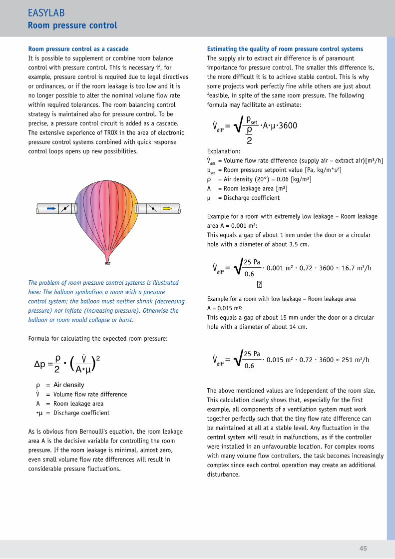
45
EASYLABRoom pressure control
Room pressure control as a cascadeIt is possible to supplement or combine room balance control with pressure control. This is necessary if, for example, pressure control is required due to legal directives or ordinances, or if the room leakage is too low and it is no longer possible to alter the nominal volume flow rate within required tolerances. The room balancing control strategy is maintained also for pressure control. To be precise, a pressure control circuit is added as a cascade. The extensive experience of TROX in the area of electronic pressure control systems combined with quick response control loops opens up new possibilities.
The problem of room pressure control systems is illustrated here: The balloon symbolises a room with a pressure control system; the balloon must neither shrink (decreasing pressure) nor inflate (increasing pressure). Otherwise the balloon or room would collapse or burst.
Formula for calculating the expected room pressure:
∆p = ρ . ( )2 2 A*μ ρ = Air density = Volume flow rate difference A = Room leakage area
*μ = Discharge coefficient
As is obvious from Bernoulli's equation, the room leakage area A is the decisive variable for controlling the room pressure. If the room leakage is minimal, almost zero, even small volume flow rate differences will result in considerable pressure fluctuations.
Estimating the quality of room pressure control systemsThe supply air to extract air difference is of paramount importance for pressure control. The smaller this difference is, the more difficult it is to achieve stable control. This is why some projects work perfectly fine while others are just about feasible, in spite of the same room pressure. The following formula may facilitate an estimate:
diff = √ pset .A.μ.3600 ρ 2 Explanation:diff = Volume flow rate difference (supply air – extract air)[m³/h]pset = Room pressure setpoint value [Pa, kg/m*s²]ρ = Air density (20°) = 0.06 [kg/m³]A = Room leakage area [m²]µ = Discharge coefficient
Example for a room with extremely low leakage – Room leakage area A = 0.001 m²:This equals a gap of about 1 mm under the door or a circular hole with a diameter of about 3.5 cm.
diff = √25 Pa . 0.001 m2 . 0.72 . 3600 ≈ 16.7 m3/h 0.6 ㎛ Example for a room with low leakage – Room leakage area A = 0.015 m²:This equals a gap of about 15 mm under the door or a circular hole with a diameter of about 14 cm.
diff = √25 Pa . 0.015 m2 . 0.72 . 3600 ≈ 251 m3/h 0.6 The above mentioned values are independent of the room size. This calculation clearly shows that, especially for the first example, all components of a ventilation system must work together perfectly such that the tiny flow rate difference can be maintained at all at a stable level. Any fluctuation in the central system will result in malfunctions, as if the controller were installed in an unfavourable location. For complex rooms with many volume flow controllers, the task becomes increasingly complex since each control operation may create an additional disturbance.
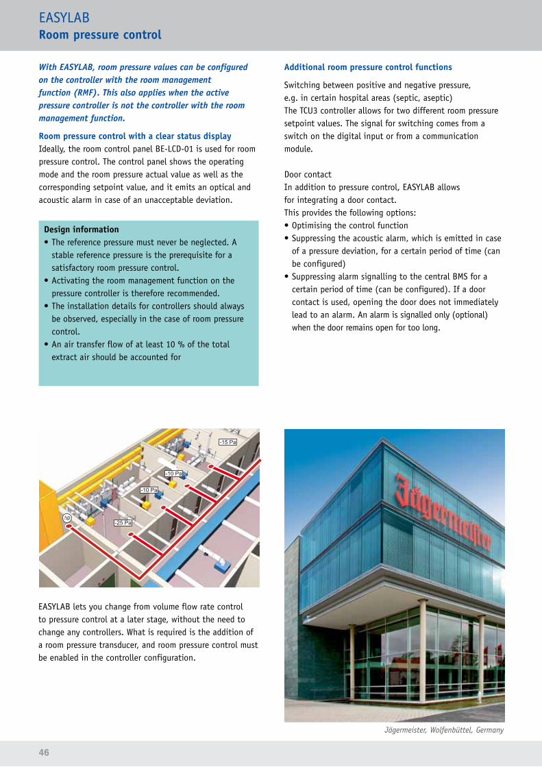
46
EASYLABRoom pressure control
With EASYLAB, room pressure values can be configured on the controller with the room management function (RMF). This also applies when the active pressure controller is not the controller with the room management function.
Room pressure control with a clear status displayIdeally, the room control panel BE-LCD-01 is used for room pressure control. The control panel shows the operating mode and the room pressure actual value as well as the corresponding setpoint value, and it emits an optical and acoustic alarm in case of an unacceptable deviation.
Design information• The reference pressure must never be neglected. A
stable reference pressure is the prerequisite for a satisfactory room pressure control.
• Activating the room management function on the pressure controller is therefore recommended.
• The installation details for controllers should always be observed, especially in the case of room pressure control.
• An air transfer flow of at least 10 % of the total extract air should be accounted for
EASYLAB lets you change from volume flow rate control to pressure control at a later stage, without the need to change any controllers. What is required is the addition of a room pressure transducer, and room pressure control must be enabled in the controller configuration.
Additional room pressure control functions
Switching between positive and negative pressure, e.g. in certain hospital areas (septic, aseptic)The TCU3 controller allows for two different room pressure setpoint values. The signal for switching comes from a switch on the digital input or from a communication module.
Door contactIn addition to pressure control, EASYLAB allows for integrating a door contact.This provides the following options:• Optimising the control function• Suppressing the acoustic alarm, which is emitted in case
of a pressure deviation, for a certain period of time (can be configured)
• Suppressing alarm signalling to the central BMS for a certain period of time (can be configured). If a door contact is used, opening the door does not immediately lead to an alarm. An alarm is signalled only (optional) when the door remains open for too long.
Jägermeister, Wolfenbüttel, Germany
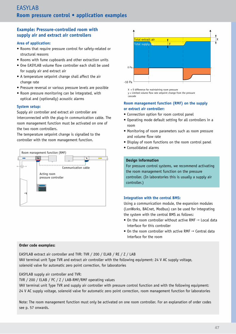
47
EASYLABRoompressurecontrol•applicationexamples
Example: Pressure-controlled room with supply air and extract air controllers
Area of application:• Rooms that require pressure control for safety-related or
structural reasons• Rooms with fume cupboards and other extraction units• One EASYLAB volume flow controller each shall be used
for supply air and extract air• A temperature setpoint change shall affect the air
change rate• Pressure reversal or various pressure levels are possible• Room pressure monitoring can be integrated, with
optical and (optionally) acoustic alarms
System setup:Supply air controller and extract air controller are interconnected with the plug-in communication cable. The room management function must be activated on one of the two room controllers.The temperature setpoint change is signalled to the controller with the room management function.
Acting room pressure controller
Communication cable
Room management function (RMF)
Order code examples:
EASYLAB extract air controller and TVR: TVR / 200 / ELAB / RE / Z / LABVAV terminal unit Type TVR and extract air controller with the following equipment: 24 V AC supply voltage, solenoid valve for automatic zero point correction, for laboratories
EASYLAB supply air controller and TVR:TVR / 200 / ELAB / PC / Z / LAB-RMF/RMF operating valuesVAV terminal unit Type TVR and supply air controller with pressure control function and with the following equipment: 24 V AC supply voltage, solenoid valve for automatic zero point correction, room management function for laboratories
Note: The room management function must only be activated on one room controller. For an explanation of order codes see p. 57 onwards.
Total supply airTotal extract air
0 Pa
-10 Pa
X
X = difference for maintaining room pressurey = Limited volume flow rate setpoint change from the pressure cascade
y
Room management function (RMF) on the supply or extract air controller:• Connection option for room control panel• Operating mode default setting for all controllers in a
room• Monitoring of room parameters such as room pressure
and volume flow rate• Display of room functions on the room control panel• Consolidated alarms
Design informationFor pressure control systems, we recommend activating the room management function on the pressure controller. (In laboratories this is usually a supply air controller.)
Integration with the central BMS:Using a communication module, the expansion modules (LonWorks, BACnet, Modbus) can be used for integrating the system with the central BMS as follows:• On the room controller without active RMF → Local data
interface for this controller• On the room controller with active RMF → Central data
interface for the room

48
Max-Planck-Institut, Münster, Germany

49
Monitoring system FMS
For the monitoring of volume flows, differential pressures and face velocity
Monitoring system
Areas of applicationWhile complete solutions for the control and monitoring of volume flow rates do have their advantages, there are areas of application that may require the monitoring of volume flow rates, of differential pressures or of face velocities only. This is where Type FMS monitoring systems may be used. These self-powered systems for the electronic monitoring of volume flow rate, differential pressure or face velocity in fume cupboards, extractor arms and similar components are suitable for new buildings as well as for refurbishment projects. The FMS monitoring systems meet the requirements of EN 14175 for fume cupboards. They are equipped with a microprocessor with an undeletable program for monitoring the safety functions. The systems are easy and safe to use, and provide maximum energy efficiency and data transparency. The system data is stored in EEPROM memory and hence safe in case of a power failure. Due to its modulare structure, the monitoring system can be easily adapted to individual requirements. For example, an additional differential pressure transducer is available to monitor the supportive flow fan.
Depending on the application, the control panel provides information on the correct volume flow rate. If the actual value deviates from the set monitoring value, an optical and an acoustic alarm is emitted. A volt-free changeover contact can be used to signal an alarm to the central BMS.
The monitoring system can be set up for specific functions during commissioning (by others) using the EasyConnect commissioning software.
Features of the FMS monitoring system – Easy installation, expansion and commissioning due to plug connections
– Sockets for the most important connections are located on the outside of the casing
– Monitoring hardware can be expanded with modules – Adaptable control panels for fume cupboards – Innovative operation to support bespoke project requirements
– Easy installation due to interactive EasyConnect configuration software
– Power supply unit for supply voltage 90 - 250 V AC
VariantsTwo different basic systems are available:
FMS-1: Monitoring system with integral diaphragm pressure transducer and measuring probe (part of the supply package) for monitoring the differential pressure or volume flow rate
FMS-2: Monitoring system for external 0-(2)–10 V DC signals, e.g. from a face velocity transducer, volume flow controller or external differential pressure transducer
TROX EasyConnect PC software for FMS-1/FMS-2The TROX EasyConnect PC software is used to adapt the FMS-1/FMS-2 monitoring systems to the actual area of application (to be performed by others).
• Clear, menu-driven navigation• Monitoring values, types of alarms and additional
functions can be set• Software for notebook or PC with Windows operating
system• A TROX communication cable or a Bluetooth module for
EasyConnect is used to connect the monitoring system to the PC or notebook
The software can be installed on any PC or notebook with Microsoft Windows operating system.
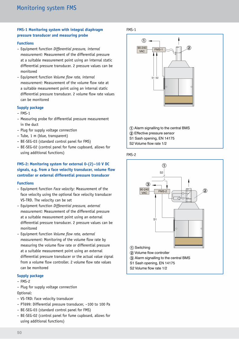
50
Monitoring system FMS
FMS-1 Monitoring system with integral diaphragm pressure transducer and measuring probe
Functions – Equipment function Differential pressure, internal measurement: Measurement of the differential pressure at a suitable measurement point using an internal static differential pressure transducer. 2 pressure values can be monitored
– Equipment function Volume flow rate, internal measurement: Measurement of the volume flow rate at a suitable measurement point using an internal static differential pressure transducer. 2 volume flow rate values can be monitored
Supply package – FMS-1 – Measuring probe for differential pressure measurement in the duct
– Plug for supply voltage connection – Tube, 1 m (blue, transparent) – BE-SEG-03 (standard control panel for FMS) – BE-SEG-02 (control panel for fume cupboard, allows for using additional functions)
FMS-2:Monitoringsystemforexternal0-(2)–10 V DC signals, e.g. from a face velocity transducer, volume flow controller or external differential pressure transducer
Functions – Equipment function Face velocity: Measurement of the face velocity using the optional face velocity transducer VS-TRD. The velocity can be set
– Equipment function Differential pressure, external measurement: Measurement of the differential pressure at a suitable measurement point using an external differential pressure transducer. 2 pressure values can be monitored
– Equipment function Volume flow rate, external measurement: Monitoring of the volume flow rate by measuring the volume flow rate or differential pressure at a suitable measurement point using an external differential pressure transducer or the actual value signal from a volume flow controller. 2 volume flow rate values can be monitored
Supply package – FMS-2 – Plug for supply voltage connection
Optional: – VS-TRD: Face velocity transducer – PT699: Differential pressure transducer, –100 to 100 Pa – BE-SEG-03 (standard control panel for FMS) – BE-SEG-02 (control panel for fume cupboard, allows for using additional functions)
FMS-1
S1 S2
FMS-190-240VAC
①
① Alarm signalling to the central BMS② Effective pressure sensorS1 Sash opening, EN 14175S2 Volume flow rate 1/2
②
FMS-2
S1
S2
FMS-290-240VAC
①
②③
① Switching② Volume flow controller③ Alarm signalling to the central BMSS1 Sash opening, EN 14175S2 Volume flow rate 1/2
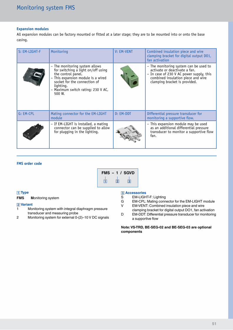
51
Monitoring system FMS
FMS – 1 / SGVD
TypeFMS Monitoring system
Variant1 Monitoring system with integral diaphragm pressure
transducer and measuring probe2 Monitoring system for external 0-(2)–10 V DC signals
AccessoriesS EM-LIGHT-F: LightingG EM-CPL: Mating connector for the EM-LIGHT moduleV EM-VENT: Combined insulation piece and wire
clamping bracket for digital output DO1, fan activationD EM-DDT: Differential pressure transducer for monitoring
a supportive flow
Note: VS-TRD, BE-SEG-02 and BE-SEG-03 are optional components
FMS order code
Expansion modulesAll expansion modules can be factory mounted or fitted at a later stage; they are to be mounted into or onto the base casing.
S: EM-LIGHT-F Monitoring V: EM-VENT Combined insulation piece and wire clamping bracket for digital output DO1, fan activation
– The monitoring system allows for switching a light on/off using the control panel.
– This expansion module is a wired socket for the connection of lighting.
– Maximum switch rating: 230 V AC, 500 W.
– The monitoring system can be used to activate or deactivate a fan.
– In case of 230 V AC power supply, this combined insulation piece and wire clamping bracket is provided.
G: EM-CPL Mating connector for the EM-LIGHT module
D: EM-DDT Differential pressure transducer for monitoring a supportive flow.
– If EM-LIGHT is installed, a mating connector can be supplied to allow for plugging in the lighting.
– This expansion module may be used as an additional differential pressure transducer to monitor a supportive flow fan.
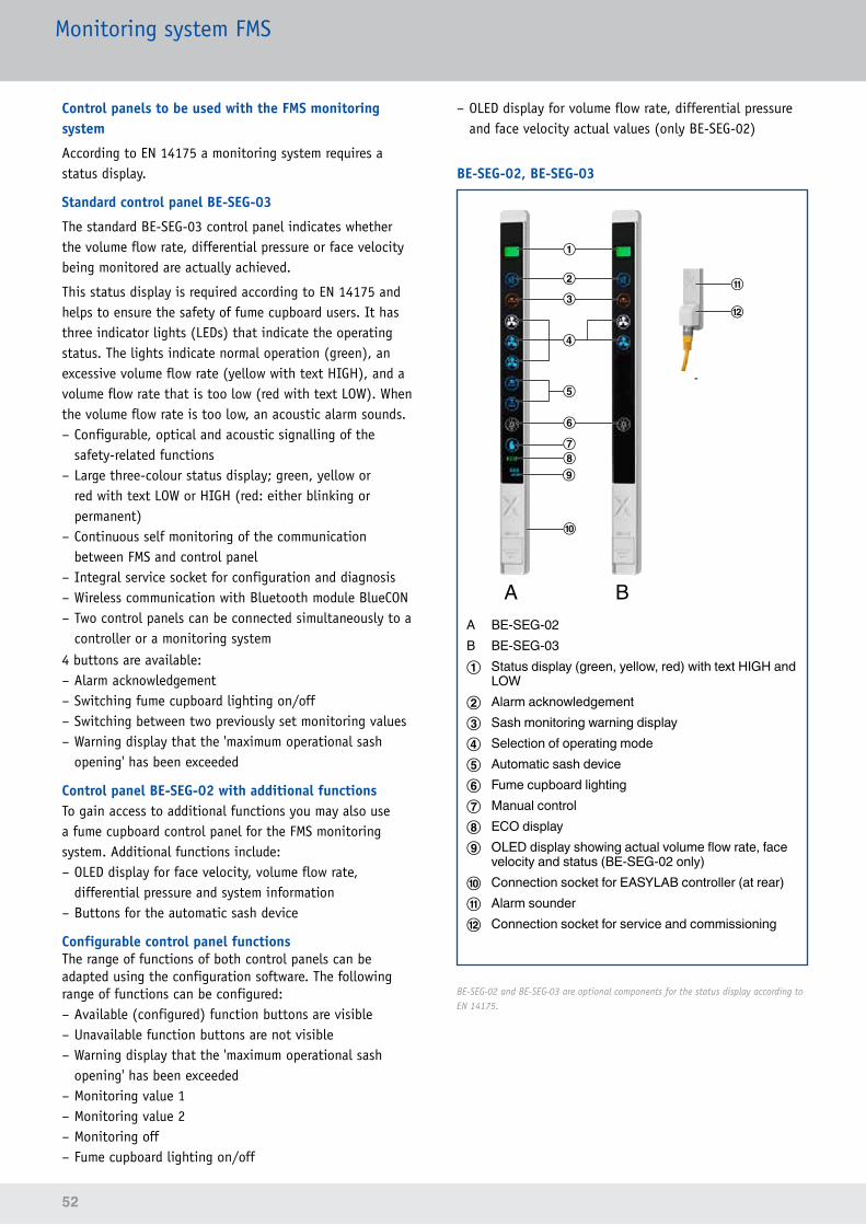
52
Monitoring system FMS
Control panels to be used with the FMS monitoring system
According to EN 14175 a monitoring system requires a status display.
Standard control panel BE-SEG-03
The standard BE-SEG-03 control panel indicates whether the volume flow rate, differential pressure or face velocity being monitored are actually achieved.
This status display is required according to EN 14175 and helps to ensure the safety of fume cupboard users. It has three indicator lights (LEDs) that indicate the operating status. The lights indicate normal operation (green), an excessive volume flow rate (yellow with text HIGH), and a volume flow rate that is too low (red with text LOW). When the volume flow rate is too low, an acoustic alarm sounds. – Configurable, optical and acoustic signalling of the safety-related functions
– Large three-colour status display; green, yellow or red with text LOW or HIGH (red: either blinking or permanent)
– Continuous self monitoring of the communication between FMS and control panel
– Integral service socket for configuration and diagnosis – Wireless communication with Bluetooth module BlueCON – Two control panels can be connected simultaneously to a controller or a monitoring system
4 buttons are available: – Alarm acknowledgement – Switching fume cupboard lighting on/off – Switching between two previously set monitoring values – Warning display that the 'maximum operational sash opening' has been exceeded
Control panel BE-SEG-02 with additional functionsTo gain access to additional functions you may also use a fume cupboard control panel for the FMS monitoring system. Additional functions include: – OLED display for face velocity, volume flow rate, differential pressure and system information
– Buttons for the automatic sash device
Configurable control panel functionsThe range of functions of both control panels can be adapted using the configuration software. The following range of functions can be configured: – Available (configured) function buttons are visible – Unavailable function buttons are not visible – Warning display that the 'maximum operational sash opening' has been exceeded
– Monitoring value 1 – Monitoring value 2 – Monitoring off – Fume cupboard lighting on/off
– OLED display for volume flow rate, differential pressure and face velocity actual values (only BE-SEG-02)
BE-SEG-02, BE-SEG-03
⑤
①
⑧⑦
⑥
③② ⑪
⑫
⑩
⑨ ⑪
A
A
B B
④
A BE-SEG-02B BE-SEG-03① Status display (green, yellow, red) with text HIGH and
LOW② Alarm acknowledgement③ Sash monitoring warning display④ Selection of operating mode⑤ Automatic sash device⑥ Fume cupboard lighting⑦ Manual control⑧ ECO display⑨ OLED display showing actual volume flow rate, face
velocity and status (BE-SEG-02 only)⑩ Connection socket for EASYLAB controller (at rear)⑪ Alarm sounder⑫ Connection socket for service and commissioning
BE-SEG-02 and BE-SEG-03 are optional components for the status display according to EN 14175.
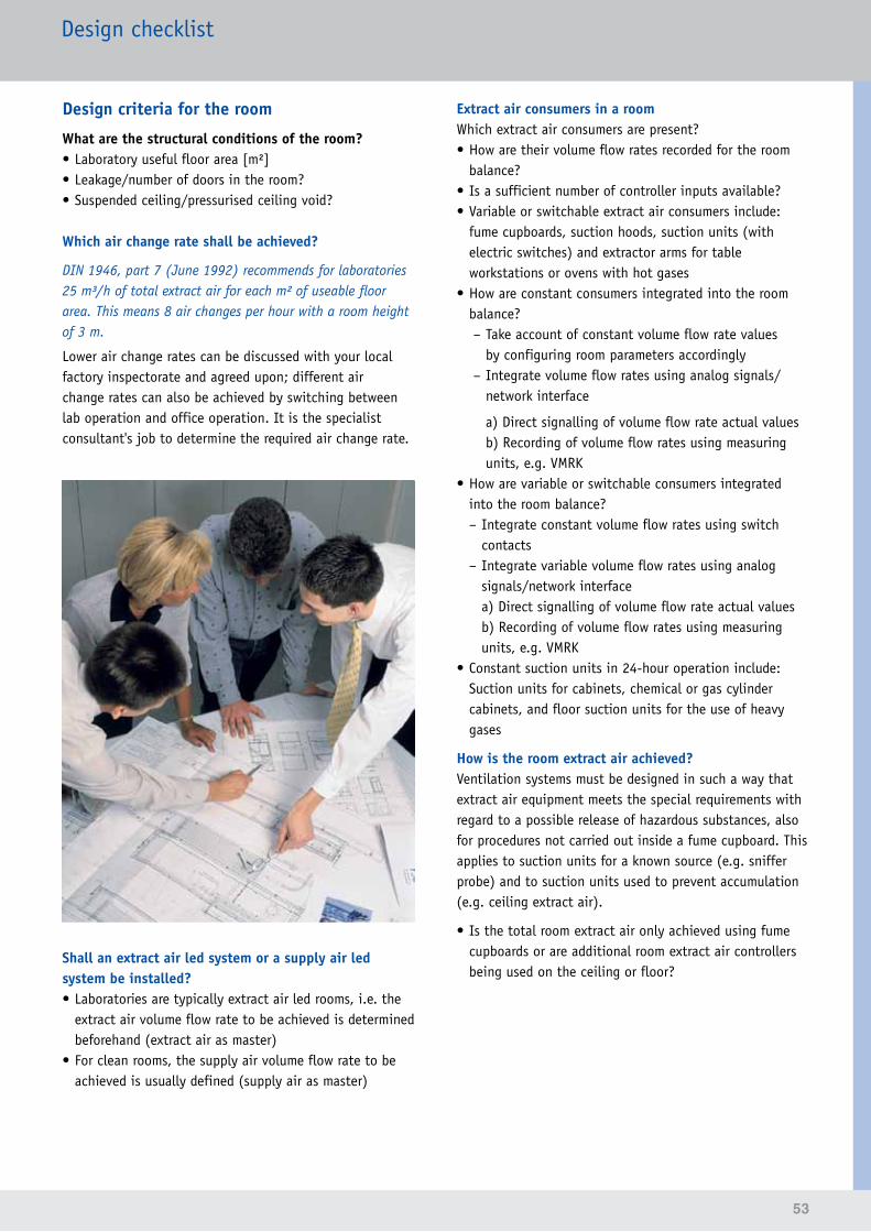
53
Design checklist
Design criteria for the room
What are the structural conditions of the room?• Laboratory useful floor area [m²]• Leakage/number of doors in the room?• Suspended ceiling/pressurised ceiling void?
Which air change rate shall be achieved?
DIN 1946, part 7 (June 1992) recommends for laboratories 25 m³/h of total extract air for each m² of useable floor area. This means 8 air changes per hour with a room height of 3 m.
Lower air change rates can be discussed with your local factory inspectorate and agreed upon; different air change rates can also be achieved by switching between lab operation and office operation. It is the specialist consultant's job to determine the required air change rate.
Shall an extract air led system or a supply air led system be installed?• Laboratories are typically extract air led rooms, i.e. the
extract air volume flow rate to be achieved is determined beforehand (extract air as master)
• For clean rooms, the supply air volume flow rate to be achieved is usually defined (supply air as master)
Extract air consumers in a roomWhich extract air consumers are present?• How are their volume flow rates recorded for the room
balance?• Is a sufficient number of controller inputs available?• Variable or switchable extract air consumers include:
fume cupboards, suction hoods, suction units (with electric switches) and extractor arms for table workstations or ovens with hot gases
• How are constant consumers integrated into the room balance?
– Take account of constant volume flow rate values by configuring room parameters accordingly
– Integrate volume flow rates using analog signals/network interface
a) Direct signalling of volume flow rate actual valuesb) Recording of volume flow rates using measuring units, e.g. VMRK
• How are variable or switchable consumers integrated into the room balance? – Integrate constant volume flow rates using switch contacts
– Integrate variable volume flow rates using analog signals/network interfacea) Direct signalling of volume flow rate actual valuesb) Recording of volume flow rates using measuring units, e.g. VMRK
• Constant suction units in 24-hour operation include: Suction units for cabinets, chemical or gas cylinder cabinets, and floor suction units for the use of heavy gases
How is the room extract air achieved?Ventilation systems must be designed in such a way that extract air equipment meets the special requirements with regard to a possible release of hazardous substances, also for procedures not carried out inside a fume cupboard. This applies to suction units for a known source (e.g. sniffer probe) and to suction units used to prevent accumulation (e.g. ceiling extract air).
• Is the total room extract air only achieved using fume cupboards or are additional room extract air controllers being used on the ceiling or floor?
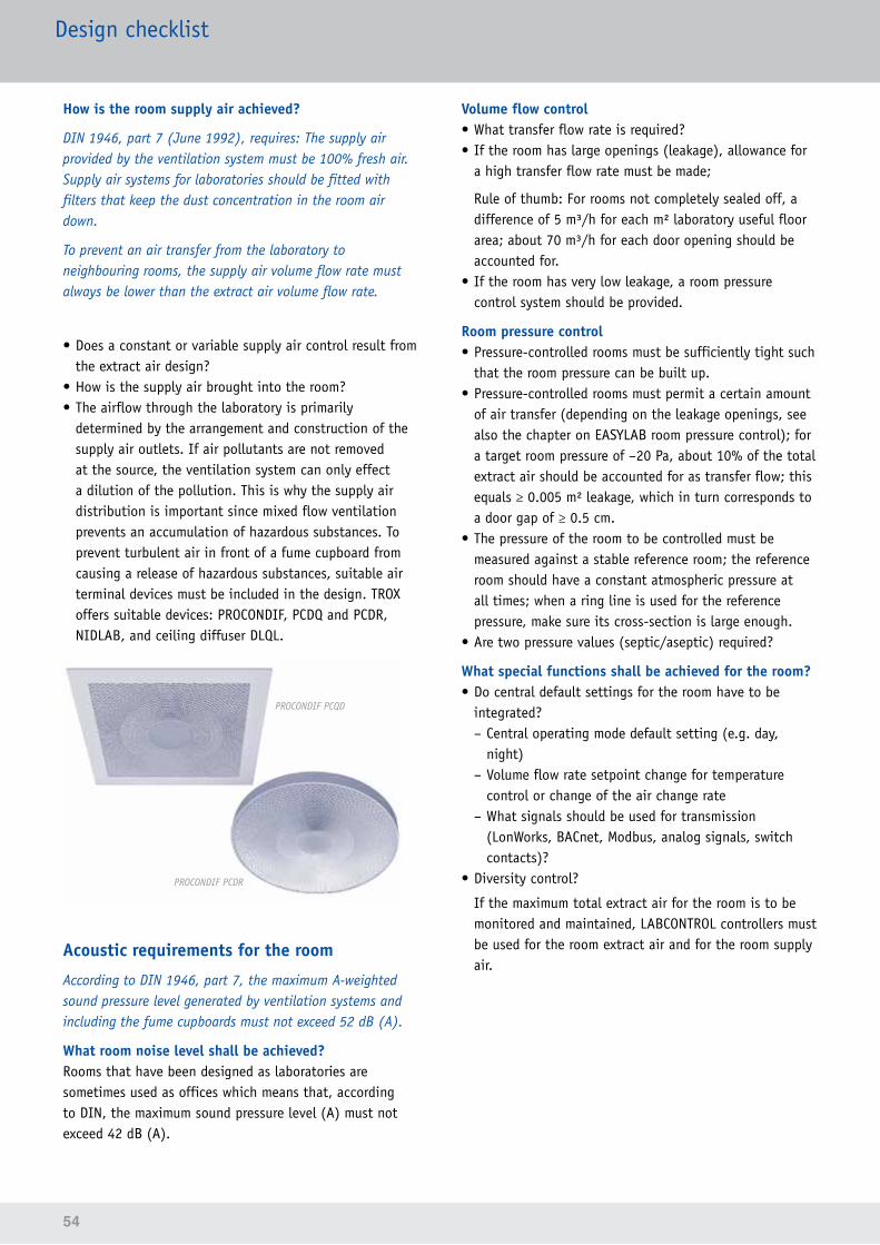
54
Design checklist
How is the room supply air achieved?
DIN 1946, part 7 (June 1992), requires: The supply air provided by the ventilation system must be 100% fresh air. Supply air systems for laboratories should be fitted with filters that keep the dust concentration in the room air down.
To prevent an air transfer from the laboratory to neighbouring rooms, the supply air volume flow rate must always be lower than the extract air volume flow rate.
• Does a constant or variable supply air control result from the extract air design?
• How is the supply air brought into the room?• The airflow through the laboratory is primarily
determined by the arrangement and construction of the supply air outlets. If air pollutants are not removed at the source, the ventilation system can only effect a dilution of the pollution. This is why the supply air distribution is important since mixed flow ventilation prevents an accumulation of hazardous substances. To prevent turbulent air in front of a fume cupboard from causing a release of hazardous substances, suitable air terminal devices must be included in the design. TROX offers suitable devices: PROCONDIF, PCDQ and PCDR, NIDLAB, and ceiling diffuser DLQL.
PROCONDIF PCDR
PROCONDIF PCQD
Acoustic requirements for the room
According to DIN 1946, part 7, the maximum A-weighted sound pressure level generated by ventilation systems and including the fume cupboards must not exceed 52 dB (A).
What room noise level shall be achieved?Rooms that have been designed as laboratories are sometimes used as offices which means that, according to DIN, the maximum sound pressure level (A) must not exceed 42 dB (A).
Volume flow control• What transfer flow rate is required?• If the room has large openings (leakage), allowance for
a high transfer flow rate must be made;
Rule of thumb: For rooms not completely sealed off, a difference of 5 m³/h for each m² laboratory useful floor area; about 70 m³/h for each door opening should be accounted for.
• If the room has very low leakage, a room pressure control system should be provided.
Room pressure control• Pressure-controlled rooms must be sufficiently tight such
that the room pressure can be built up.• Pressure-controlled rooms must permit a certain amount
of air transfer (depending on the leakage openings, see also the chapter on EASYLAB room pressure control); for a target room pressure of –20 Pa, about 10% of the total extract air should be accounted for as transfer flow; this equals ≥ 0.005 m² leakage, which in turn corresponds to a door gap of ≥ 0.5 cm.
• The pressure of the room to be controlled must be measured against a stable reference room; the reference room should have a constant atmospheric pressure at all times; when a ring line is used for the reference pressure, make sure its cross-section is large enough.
• Are two pressure values (septic/aseptic) required?
What special functions shall be achieved for the room?• Do central default settings for the room have to be
integrated? – Central operating mode default setting (e.g. day, night)
– Volume flow rate setpoint change for temperature control or change of the air change rate
– What signals should be used for transmission (LonWorks, BACnet, Modbus, analog signals, switch contacts)?
• Diversity control?
If the maximum total extract air for the room is to be monitored and maintained, LABCONTROL controllers must be used for the room extract air and for the room supply air.
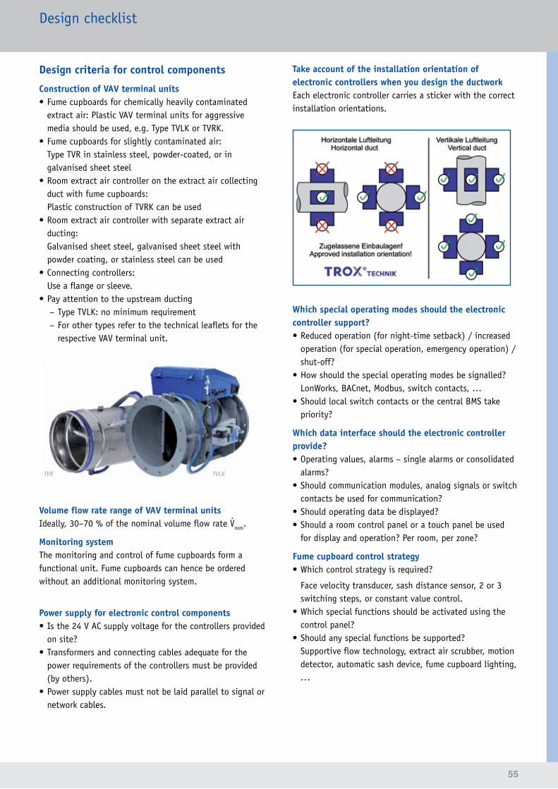
55
Design checklist
Design criteria for control components
Construction of VAV terminal units• Fume cupboards for chemically heavily contaminated
extract air: Plastic VAV terminal units for aggressive media should be used, e.g. Type TVLK or TVRK.
• Fume cupboards for slightly contaminated air:Type TVR in stainless steel, powder-coated, or in galvanised sheet steel
• Room extract air controller on the extract air collecting duct with fume cupboards:Plastic construction of TVRK can be used
• Room extract air controller with separate extract air ducting:Galvanised sheet steel, galvanised sheet steel with powder coating, or stainless steel can be used
• Connecting controllers:Use a flange or sleeve.
• Pay attention to the upstream ducting – Type TVLK: no minimum requirement – For other types refer to the technical leaflets for the respective VAV terminal unit.
TVR TVLK
Volume flow rate range of VAV terminal unitsIdeally, 30–70 % of the nominal volume flow rate nom.
Monitoring systemThe monitoring and control of fume cupboards form a functional unit. Fume cupboards can hence be ordered without an additional monitoring system.
Power supply for electronic control components• Is the 24 V AC supply voltage for the controllers provided
on site?• Transformers and connecting cables adequate for the
power requirements of the controllers must be provided (by others).
• Power supply cables must not be laid parallel to signal or network cables.
Take account of the installation orientation of electronic controllers when you design the ductworkEach electronic controller carries a sticker with the correct installation orientations.
Which special operating modes should the electronic controller support?• Reduced operation (for night-time setback) / increased
operation (for special operation, emergency operation) / shut-off?
• How should the special operating modes be signalled? LonWorks, BACnet, Modbus, switch contacts, …
• Should local switch contacts or the central BMS take priority?
Which data interface should the electronic controller provide?• Operating values, alarms – single alarms or consolidated
alarms?• Should communication modules, analog signals or switch
contacts be used for communication?• Should operating data be displayed?• Should a room control panel or a touch panel be used
for display and operation? Per room, per zone?
Fume cupboard control strategy• Which control strategy is required?
Face velocity transducer, sash distance sensor, 2 or 3 switching steps, or constant value control.
• Which special functions should be activated using the control panel?
• Should any special functions be supported?Supportive flow technology, extract air scrubber, motion detector, automatic sash device, fume cupboard lighting, ...
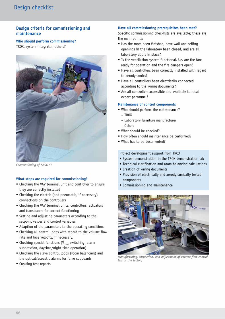
56
Design checklist
Design criteria for commissioning and maintenance
Who should perform commissioning?TROX, system integrator, others?
Commissioning of EASYLAB
What steps are required for commissioning?• Checking the VAV terminal unit and controller to ensure
they are correctly installed• Checking the electric (and pneumatic, if necessary)
connections on the controllers• Checking the VAV terminal units, controllers, actuators
and transducers for correct functioning• Setting and adjusting parameters according to the
setpoint values and control variables• Adaption of the parameters to the operating conditions• Checking all control loops with regard to the volume flow
rate and face velocity, if necessary.• Checking special functions (const switching, alarm
suppression, daytime/night-time operation)• Checking the slave control loops (room balancing) and
the optical/acoustic alarms for fume cupboards• Creating test reports
Have all commissioning prerequisites been met?Specific commissioning checklists are available; these are the main points:• Has the room been finished, have wall and ceiling
openings in the laboratory been closed, and are all laboratory doors in place?
• Is the ventilation system functional, i.e. are the fans ready for operation and the fire dampers open?
• Have all controllers been correctly installed with regard to aerodynamics?
• Have all controllers been electrically connected according to the wiring documents?
• Are all controllers accessible and available to local expert personnel?
Maintenance of control components• Who should perform the maintenance?
– TROX – Laboratory furniture manufacturer – Others
• What should be checked?• How often should maintenance be performed?• What has to be documented?
Project development support from TROX• System demonstration in the TROX demonstration lab• Technical clarification and room balancing calculations• Creation of wiring documents• Provision of electrically and aerodynamically tested
components• Commissioning and maintenance
Manufacturing, inspection, and adjustment of volume flow control-lers at the factory
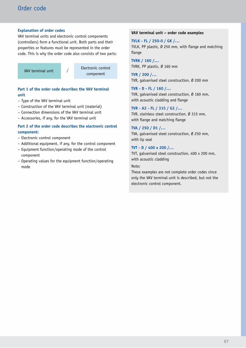
57
Order code
Explanation of order codesVAV terminal units and electronic control components (controllers) form a functional unit. Both parts and their properties or features must be represented in the order code. This is why the order code also consists of two parts:
/VAV terminal unitElectronic control
component
Part 1 of the order code describes the VAV terminal unit – Type of the VAV terminal unit – Construction of the VAV terminal unit (material) – Connection dimensions of the VAV terminal unit – Accessories, if any, for the VAV terminal unit
Part 2 of the order code describes the electronic control component: – Electronic control component – Additional equipment, if any, for the control component – Equipment function/operating mode of the control component
– Operating values for the equipment function/operating mode
VAV terminal unit – order code examples
TVLK - FL / 250-0 / GK /...TVLK, PP plastic, Ø 250 mm, with flange and matching flange
TVRK / 160 /...TVRK, PP plastic, Ø 160 mm
TVR / 200 /...TVR, galvanised steel construction, Ø 200 mm
TVR - D - FL / 160 /...TVR, galvanised steel construction, Ø 160 mm, with acoustic cladding and flange
TVR - A2 - FL / 315 / G2 /...TVR, stainless steel construction, Ø 315 mm, with flange and matching flange
TVA / 250 / D1 /...TVA, galvanised steel construction, Ø 250 mm, with lip seal
TVT - D / 400 x 200 /...TVT, galvanised steel construction, 400 x 200 mm, with acoustic cladding
Note:These examples are not complete order codes since only the VAV terminal unit is described, but not the electronic control component.
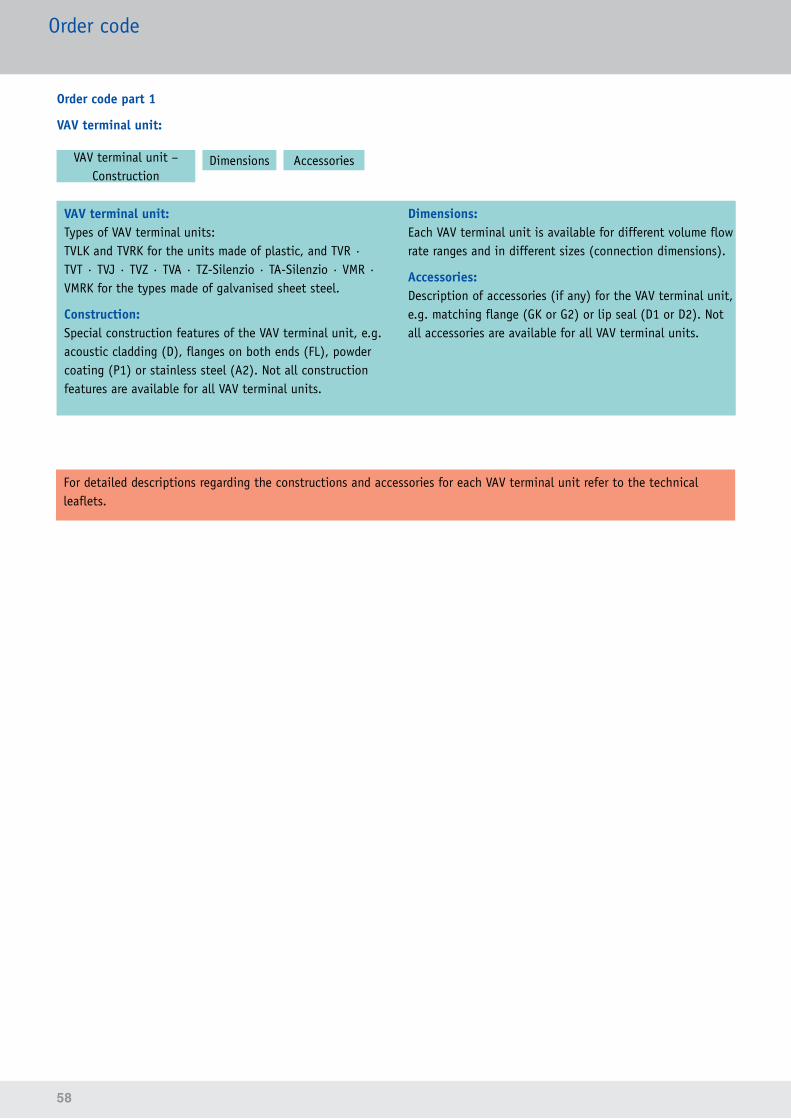
58
For detailed descriptions regarding the constructions and accessories for each VAV terminal unit refer to the technical leaflets.
Order code
VAV terminal unit:Types of VAV terminal units:TVLK and TVRK for the units made of plastic, and TVR · TVT · TVJ · TVZ · TVA · TZ-Silenzio · TA-Silenzio · VMR · VMRK for the types made of galvanised sheet steel.
Construction: Special construction features of the VAV terminal unit, e.g. acoustic cladding (D), flanges on both ends (FL), powder coating (P1) or stainless steel (A2). Not all construction features are available for all VAV terminal units.
Dimensions:Each VAV terminal unit is available for different volume flow rate ranges and in different sizes (connection dimensions).
Accessories:Description of accessories (if any) for the VAV terminal unit, e.g. matching flange (GK or G2) or lip seal (D1 or D2). Not all accessories are available for all VAV terminal units.
VAV terminal unit – Construction
Dimensions Accessories
Order code part 1
VAV terminal unit:
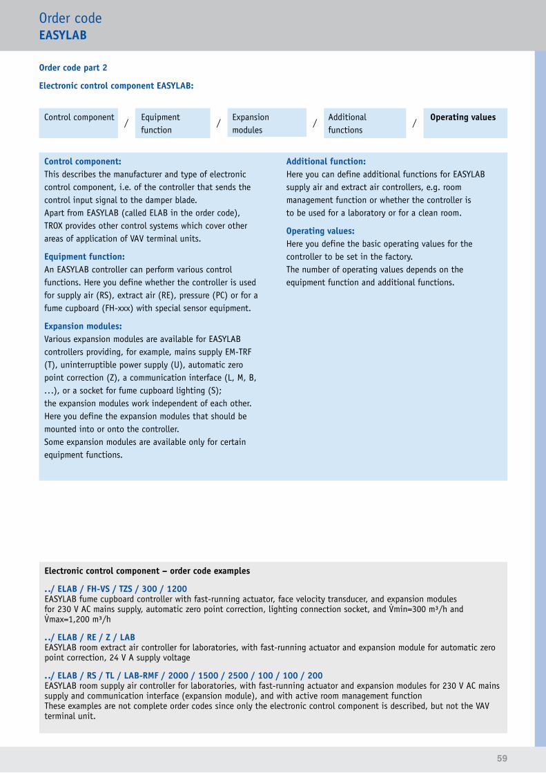
59
Order codeEASYLAB
Order code part 2
Electronic control component EASYLAB:
Control component Operating valuesAdditional functions
Expansion modules
Equipment function
/ / / /
Control component:This describes the manufacturer and type of electronic control component, i.e. of the controller that sends the control input signal to the damper blade.Apart from EASYLAB (called ELAB in the order code), TROX provides other control systems which cover other areas of application of VAV terminal units.
Equipment function:An EASYLAB controller can perform various control functions. Here you define whether the controller is used for supply air (RS), extract air (RE), pressure (PC) or for a fume cupboard (FH-xxx) with special sensor equipment.
Expansion modules:Various expansion modules are available for EASYLAB controllers providing, for example, mains supply EM-TRF (T), uninterruptible power supply (U), automatic zero point correction (Z), a communication interface (L, M, B, ...), or a socket for fume cupboard lighting (S); the expansion modules work independent of each other. Here you define the expansion modules that should be mounted into or onto the controller.Some expansion modules are available only for certain equipment functions.
Additional function:Here you can define additional functions for EASYLAB supply air and extract air controllers, e.g. room management function or whether the controller is to be used for a laboratory or for a clean room.
Operating values:Here you define the basic operating values for the controller to be set in the factory.The number of operating values depends on the equipment function and additional functions.
Electronic control component – order code examples
../ ELAB / FH-VS / TZS / 300 / 1200EASYLAB fume cupboard controller with fast-running actuator, face velocity transducer, and expansion modules for 230 V AC mains supply, automatic zero point correction, lighting connection socket, and min=300 m³/h and max=1,200 m³/h
. ./ ELAB / RE / Z / LABEASYLAB room extract air controller for laboratories, with fast-running actuator and expansion module for automatic zero point correction, 24 V A supply voltage
. ./ ELAB / RS / TL / LAB-RMF / 2000 / 1500 / 2500 / 100 / 100 / 200EASYLAB room supply air controller for laboratories, with fast-running actuator and expansion modules for 230 V AC mains supply and communication interface (expansion module), and with active room management functionThese examples are not complete order codes since only the electronic control component is described, but not the VAV terminal unit.
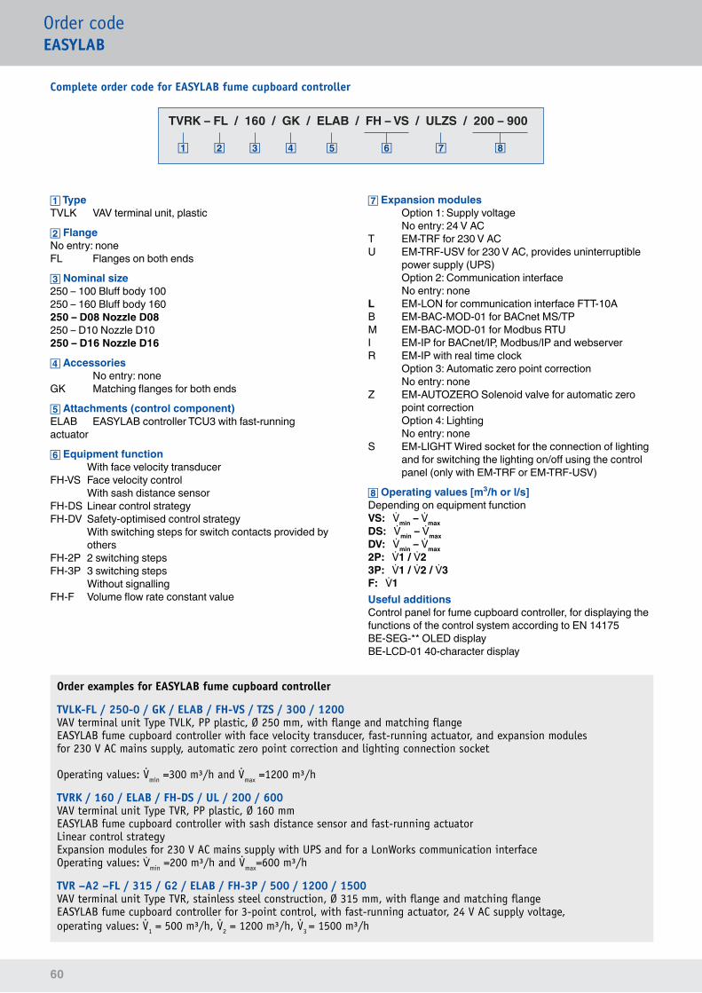
60
Order examples for EASYLAB fume cupboard controller
TVLK-FL / 250-0 / GK / ELAB / FH-VS / TZS / 300 / 1200VAV terminal unit Type TVLK, PP plastic, Ø 250 mm, with flange and matching flangeEASYLAB fume cupboard controller with face velocity transducer, fast-running actuator, and expansion modules for 230 V AC mains supply, automatic zero point correction and lighting connection socket
Operating values: min =300 m³/h and max =1200 m³/h
TVRK / 160 / ELAB / FH-DS / UL / 200 / 600VAV terminal unit Type TVR, PP plastic, Ø 160 mmEASYLAB fume cupboard controller with sash distance sensor and fast-running actuatorLinear control strategyExpansion modules for 230 V AC mains supply with UPS and for a LonWorks communication interfaceOperating values: min =200 m³/h and max=600 m³/h
TVR –A2 –FL / 315 / G2 / ELAB / FH-3P / 500 / 1200 / 1500VAV terminal unit Type TVR, stainless steel construction, Ø 315 mm, with flange and matching flangeEASYLAB fume cupboard controller for 3-point control, with fast-running actuator, 24 V AC supply voltage, operating values: 1 = 500 m³/h, 2 = 1200 m³/h, 3 = 1500 m³/h
Order codeEASYLAB
Complete order code for EASYLAB fume cupboard controller
TypeTVLK VAV terminal unit, plastic
FlangeNo entry: noneFL Flanges on both ends
Nominal size250 – 100 Bluff body 100250 – 160 Bluff body 160250 – D08 Nozzle D08250 – D10 Nozzle D10250 – D16 Nozzle D16
Accessories No entry: noneGK Matching flanges for both ends
Attachments (control component)ELAB EASYLAB controller TCU3 with fast-running actuator
Equipment function With face velocity transducerFH-VS Face velocity control With sash distance sensorFH-DS Linear control strategyFH-DV Safety-optimised control strategy With switching steps for switch contacts provided by
othersFH-2P 2 switching stepsFH-3P 3 switching steps Without signallingFH-F Volume flow rate constant value
Expansion modules Option 1: Supply voltage No entry: 24 V ACT EM-TRF for 230 V ACU EM-TRF-USV for 230 V AC, provides uninterruptible
power supply (UPS) Option 2: Communication interface No entry: noneL EM-LON for communication interface FTT-10AB EM-BAC-MOD-01 for BACnet MS/TPM EM-BAC-MOD-01 for Modbus RTUI EM-IP for BACnet/IP, Modbus/IP and webserverR EM-IP with real time clock Option 3: Automatic zero point correction No entry: noneZ EM-AUTOZERO Solenoid valve for automatic zero
point correction Option 4: Lighting No entry: noneS EM-LIGHT Wired socket for the connection of lighting
and for switching the lighting on/off using the control panel (only with EM-TRF or EM-TRF-USV)
Operating values [m³/h or l/s]Depending on equipment functionVS: min – maxDS: min – maxDV: min – max2P: 1 / 23P: 1 / 2 / 3F: 1Useful additionsControl panel for fume cupboard controller, for displaying the functions of the control system according to EN 14175BE-SEG-** OLED displayBE-LCD-01 40-character display
TVRK – FL / 160 / GK / ELAB / FH – VS / ULZS / 200 – 900
TVRK – FL / 160 / GK / ELAB / FH – VS / ULZS / 200 – 900
TVRK – FL / 160 / GK / ELAB / FH – VS / ULZS / 200 – 900
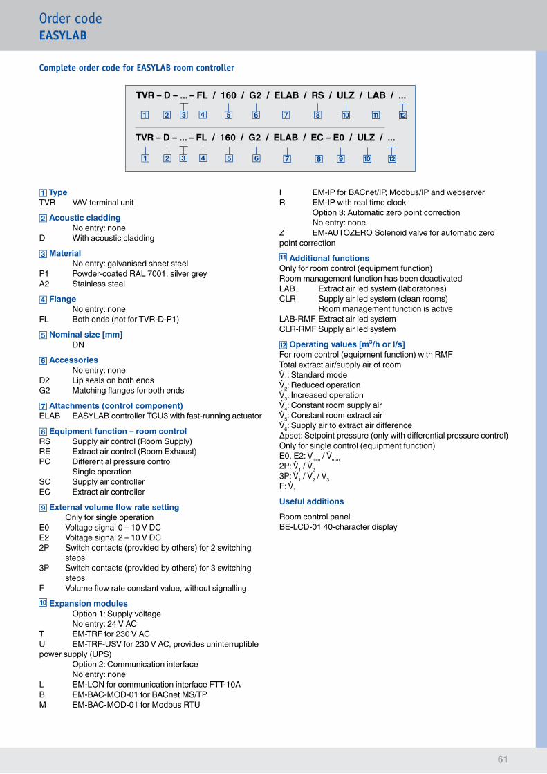
61
Order codeEASYLAB
Complete order code for EASYLAB room controller
TVR – D – ... – FL / 160 / G2 / ELAB / EC – E0 / ULZ / ...
TVR – D – ... – FL / 160 / G2 / ELAB / RS / ULZ / LAB / ...
TypeTVR VAV terminal unit
Acoustic cladding No entry: noneD With acoustic cladding
Material No entry: galvanised sheet steelP1 Powder-coated RAL 7001, silver greyA2 Stainless steel
Flange No entry: noneFL Both ends (not for TVR-D-P1)
Nominal size [mm] DN
Accessories No entry: noneD2 Lip seals on both endsG2 Matching flanges for both ends
Attachments (control component)ELAB EASYLAB controller TCU3 with fast-running actuator
Equipment function – room controlRS Supply air control (Room Supply)RE Extract air control (Room Exhaust)PC Differential pressure control Single operationSC Supply air controllerEC Extract air controller
External volume flow rate setting Only for single operationE0 Voltage signal 0 – 10 V DCE2 Voltage signal 2 – 10 V DC2P Switch contacts (provided by others) for 2 switching
steps3P Switch contacts (provided by others) for 3 switching
stepsF Volume flow rate constant value, without signalling10 Expansion modules Option 1: Supply voltage No entry: 24 V ACT EM-TRF for 230 V ACU EM-TRF-USV for 230 V AC, provides uninterruptible power supply (UPS) Option 2: Communication interface No entry: noneL EM-LON for communication interface FTT-10AB EM-BAC-MOD-01 for BACnet MS/TPM EM-BAC-MOD-01 for Modbus RTU
I EM-IP for BACnet/IP, Modbus/IP and webserverR EM-IP with real time clock Option 3: Automatic zero point correction No entry: noneZ EM-AUTOZERO Solenoid valve for automatic zero point correction11 Additional functionsOnly for room control (equipment function) Room management function has been deactivatedLAB Extract air led system (laboratories)CLR Supply air led system (clean rooms) Room management function is activeLAB-RMF Extract air led systemCLR-RMF Supply air led system
Operating values [m³/h or l/s] For room control (equipment function) with RMFTotal extract air/supply air of room1: Standard mode2: Reduced operation3: Increased operation4: Constant room supply air5: Constant room extract air6: Supply air to extract air differenceΔpset: Setpoint pressure (only with differential pressure control)Only for single control (equipment function)E0, E2: min / max 2P: 1 / 2 3P: 1 / 2 / 3 F: 1
Useful additions
Room control panelBE-LCD-01 40-character display
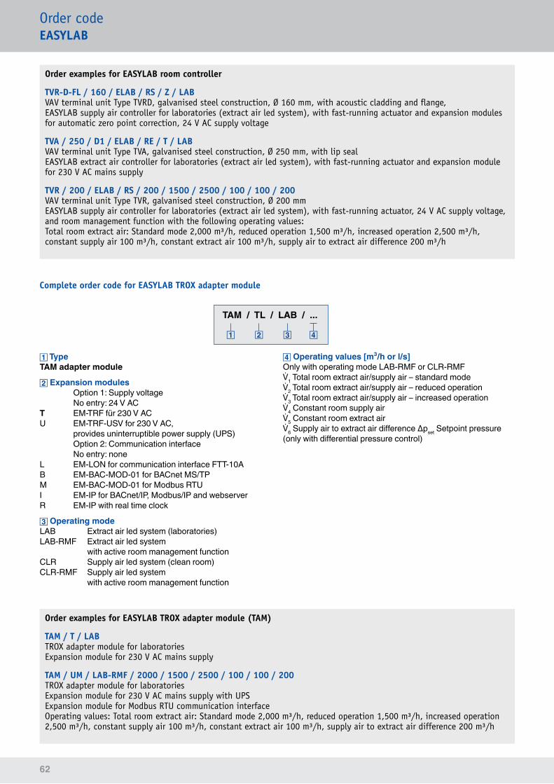
62
Order examples for EASYLAB room controller
TVR-D-FL / 160 / ELAB / RS / Z / LABVAV terminal unit Type TVRD, galvanised steel construction, Ø 160 mm, with acoustic cladding and flange, EASYLAB supply air controller for laboratories (extract air led system), with fast-running actuator and expansion modules for automatic zero point correction, 24 V AC supply voltage
TVA / 250 / D1 / ELAB / RE / T / LABVAV terminal unit Type TVA, galvanised steel construction, Ø 250 mm, with lip sealEASYLAB extract air controller for laboratories (extract air led system), with fast-running actuator and expansion module for 230 V AC mains supply
TVR / 200 / ELAB / RS / 200 / 1500 / 2500 / 100 / 100 / 200VAV terminal unit Type TVR, galvanised steel construction, Ø 200 mmEASYLAB supply air controller for laboratories (extract air led system), with fast-running actuator, 24 V AC supply voltage, and room management function with the following operating values:Total room extract air: Standard mode 2,000 m³/h, reduced operation 1,500 m³/h, increased operation 2,500 m³/h, constant supply air 100 m³/h, constant extract air 100 m³/h, supply air to extract air difference 200 m³/h
Order codeEASYLAB
Complete order code for EASYLAB TROX adapter module
Order examples for EASYLAB TROX adapter module (TAM)
TAM / T / LABTROX adapter module for laboratoriesExpansion module for 230 V AC mains supply
TAM / UM / LAB-RMF / 2000 / 1500 / 2500 / 100 / 100 / 200TROX adapter module for laboratoriesExpansion module for 230 V AC mains supply with UPSExpansion module for Modbus RTU communication interface Operating values: Total room extract air: Standard mode 2,000 m³/h, reduced operation 1,500 m³/h, increased operation 2,500 m³/h, constant supply air 100 m³/h, constant extract air 100 m³/h, supply air to extract air difference 200 m³/h
TypeTAM adapter module
Expansion modules Option 1: Supply voltage No entry: 24 V ACT EM-TRF für 230 V ACU EM-TRF-USV for 230 V AC, provides uninterruptible power supply (UPS) Option 2: Communication interface No entry: noneL EM-LON for communication interface FTT-10AB EM-BAC-MOD-01 for BACnet MS/TPM EM-BAC-MOD-01 for Modbus RTUI EM-IP for BACnet/IP, Modbus/IP and webserverR EM-IP with real time clock
Operating modeLAB Extract air led system (laboratories)LAB-RMF Extract air led system with active room management functionCLR Supply air led system (clean room)CLR-RMF Supply air led system with active room management function
Operating values [m³/h or l/s]Only with operating mode LAB-RMF or CLR-RMF1 Total room extract air/supply air – standard mode2 Total room extract air/supply air – reduced operation3 Total room extract air/supply air – increased operation4 Constant room supply air5 Constant room extract air6 Supply air to extract air difference Δpset Setpoint pressure (only with differential pressure control)
TAM / TL / LAB / ...
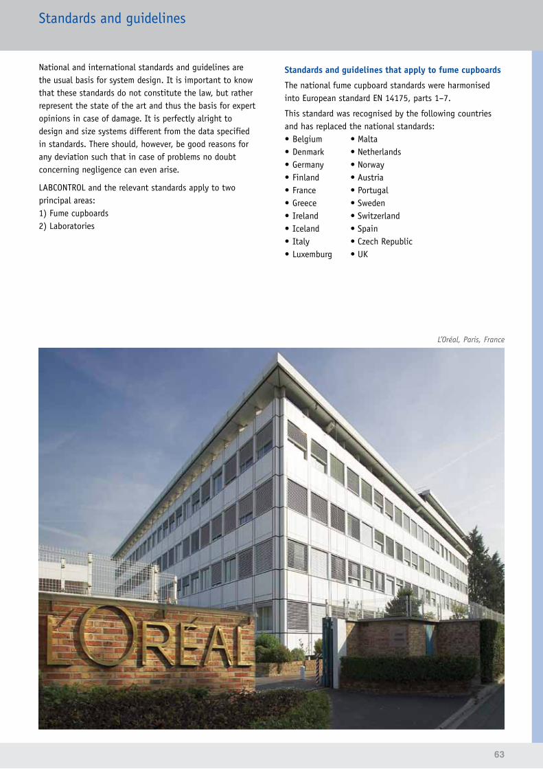
63
Standards and guidelines
National and international standards and guidelines are the usual basis for system design. It is important to know that these standards do not constitute the law, but rather represent the state of the art and thus the basis for expert opinions in case of damage. It is perfectly alright to design and size systems different from the data specified in standards. There should, however, be good reasons for any deviation such that in case of problems no doubt concerning negligence can even arise.
LABCONTROL and the relevant standards apply to two principal areas:1) Fume cupboards2) Laboratories
Standards and guidelines that apply to fume cupboards
The national fume cupboard standards were harmonised into European standard EN 14175, parts 1–7.
This standard was recognised by the following countries and has replaced the national standards:• Belgium • Malta• Denmark • Netherlands• Germany • Norway• Finland • Austria• France • Portugal• Greece • Sweden• Ireland • Switzerland• Iceland • Spain• Italy • Czech Republic• Luxemburg • UK
L’Oréal, Paris, France
64
Standards and guidelines
The following subjects of EN 14175 are particularly important for ventilation systems:
Test of fume cupboards or ancillaries (VAV system)Option 1: On-site test of a fume cupboard with VAV system
The fume cupboard with attached VAV system is tested on site. In contrast to a type test, the test result applies only to one fume cupboard and cannot be related to other fume cupboards of the same type.→ High costs, little benefit
Option 2: Type test of fume cupboards and type test of the VAV system
Option 3: Separate type test of fume cupboards and VAV system, but joint approval
The type test of a fume cupboard according to EN 14175 is performed in a test chamber and leads to volume flow rate values that are binding for this type of fume cupboard. These volume flow rate values can be applied to all fume cupboards of the same type and manufacturer.
VAV fume cupboards must meet additional test requirements with regard to the type test to EN 14175, part 3. The type test allows for several options to test the VAV system.
This is an excerpt from EN 14175, part 6 (2005-04):
'VAV systems and VAV fume cupboards can either be tested separately in accordance with 5.3 or as a combination in accordance with 5.4.As an alternative to the tests specified in 5.3, it is possible to test the VAV system together with a fume cupboard instead of the test box...'
In practice, this means that a test of the VAV system can be performed either with the test box or with a fume cupboard.
Testing VAV systems with a test box
Testing VAV systems with a fume cupboard
Result:Type-tested VAV system
Result:Type-tested VAV system or prototype-tested VAV system for this fume cupboard
Whoever requests a test will specify the goal or result.
Test of the (integrated) VAV system according to para 5.3 – A VAV system tested according to para 5.3 may be used if it fulfils the technical requirements with regard to the control functions.
Test of the VAV fume cupboard (prerequisite: type test accordingtoEN 14175,part 3) – Retention capacity with minimum and maximum volume flow rate
– Air change efficiency with minimum volume flow rate
Note:Due to pressure exerted by laboratory users, type tests for fume cupboards without a specific VAV system are fairly common since they provide the greatest possible flexibility for users. If otherwise a control system became unusable or were no longer available, the replacement control system would have to be tested, and then at a cost.
CertificationTROX EASYLAB fume cupboard controllers are developed and certified according to the applicable standards.
They meet in particular the requirements of:EN 14175 Type test methods for VAV systemsEN 60730-1 Electrical safetyEN 61000 EMC immunity to interferenceEN 55022 Radiated emissions (EMV)
This means that type-tested VAV control systems from TROX can be combined with commercially available laboratory furniture.
65
Standards and guidelines
Standards and guidelines that apply to laboratories
Depending on the type of laboratory, various guidelines may apply. The most important guidelines and standards are as follows:
•DIN 1946,part 7,Ventilationsystemsinlaboratories – Minimum extract air 25 m³/h for each m² of main useful floor area
– More stringent requirements apply to fume rooms or solvent storerooms
– Variable volume flow rates for different operating situations must be achieved
– A directed supply air flow from the outside into the laboratory is required
– Supply air must be 100% fresh air; – recirculation is not permitted
•BGR 120, Rules for safety and health protection/laboratories – Minimum extract air 25 m³/h for each m² of main useful floor area, equal to 8 air changes per hour for a 3 m high room
– Extract air may pass entirely or partially through the fume cupboards
– Note: Large extract air volume flow rates may result in undesirably high levels of turbulence inside the fume cupboard if the sash is closed
– The ventilation function of a fume cupboard must be monitored by an independent unit
– Optical and acoustic signalling are required•BGR 121, Workplace ventilation – aerodynamic
measures – Requirements of the air quality at workstations – Requirements in case of mechanical ventilation – Prevention of contaminated air transfer – Requirements for ductwork and air discharge – Requirements for emission extract devices; contaminated air must be removed using the shortest possible route.
– Ventilation system must be tested by a qualified person before commissioning, after essential changes, and at regular intervals (at least once a year). The system owner has to ensure that these requirements are met.
Ventilation systems must, primarily, dilute and remove hazardous substances. Apart from that, areas adjacent to laboratories should be protected from potentially hazardous substances.
•EN 12128,BiotechnologyContainment levels of microbiology laboratoriesFor laboratories from containment level 3: – Mechanical ventilation is required – Safe maintenance of negative pressure by the linking of supply air and extract air
– Monitoring of negative pressure with signalling and alarms
– Use of high-efficiency particulate air filters (HEPA) for the total extract air
•DIN 25425,part 1,Radioisotopelaboratories – 8 air changes per hour – Supply air must be 100% fresh air; recirculation is not permitted
– A graduated negative pressure from 10 to 30 Pa is recommended
– An independent extract air system is recommended for SK2 and required for SK3
For this purpose, a minimum extract air of 25 m³/h per square metre of main useful floor area is usually defined. This means 8 air changes per hour with a room height of 3 m (a value given in some guidelines).
The air change rate may be reduced, if necessary. In addition, BGR 120 requires that hazardous materials such as flammable liquids, or volatile, dusty, or aerosol-forming substances must only be used in the smallest possible quantities. These restrictions for use must be made public. DIN 1946 also demands clear marking at the entrances of laboratories.
DIN 1946, part 7, requires that time limits can be centrally set for variable volume flow rates. This mainly affects the number and characteristics of fans.
All listed standards require that laboratories always be operated with a negative pressure. According to EN 12128, this negative pressure must be monitored and displayed. Monitoring is also required in S2 and S3 radioisotope laboratories.In clean room laboratories or pharmaceutical production facilities, as well as in other clean rooms, the requirements for pressure may well be reversed.
66
References
Germany
Universities and collegesAachen, Bochum, Bonn, Braunschweig, Bremen, Chemnitz, Cottbus, Dort-mund, Dresden, Freiburg, Greifswald, Halle, Hamburg, Hannover, Homburg, Jena, Cologne, Leipzig, Magdeburg, Mainz, Münster, Oldenburg, Potsdam, Rostock, Tübingen, Würzburg
Universities of applied sci-enceAnsbach, Jena, Koblenz, Magdeburg, Merseburg, Neubrandenburg, Nürnberg, Rosenheim
Max Planck InstitutesDresden, Frankfurt (Main), Jena, Magdeburg, Mainz, RostockResearch institutesISAS, Dortmund,
Geisenheim, JülichLeibnitz-Institut für Polymer-forschung (Institute for Poly-mer Research), DresdenPaul Ehrlich Institute, Frank-furtUTZ, Berlin-Adlershof
HospitalsCharité, BerlinKlinikum 2000, JenaMHH HannoverOMZ, HeidelbergUniversity Hospital, AachenUniversity Hospital, Essen
Industrial and technologi-calAbbott, LudwigshafenAldrich Chemie, SteinheimALTANA BYK-Chemie, WeselAsta Medica, MainzBASF, LudwigshafenBAT, BayreuthBayer AG,Dormagen, Leverkusen,Monheim, Wuppertal
Bayer Schering Pharma, BerlinBiopark RegensburgBioscientia, IngelheimBMW, Dingolfing, MunichBoehringer, IngelheimBP, GelsenkirchenDow Corning, WiesbadenDräger Medical LübeckGoldschmidt AG, EssenGrünenthal, AachenH.C. Starck, GoslarHilti, KauferingHüls AG, MarlInfra Leuna, LeunaInfraServ Höchst, FrankfurtIZB Martinsried, MunichKist Europe, SaarbrückenLurgi Zimmer AG, FrankfurtMerck, DarmstadtRoche, PenzbergSachs, SchweinfurtSartorius, GöttingenSolvay, HannoverTechn.Park Elementis, CologneTGZ Bitterfeld Wolfen
VW Forschung, WolfsburgPublic sectorChemisches Veterinärunter-suchungsamt (Chemical Veterinary Inspectorate), MünsterLandesuntersuchungsanstalt Sachsen (State Inspectorate for Saxony), Dresden
Landesuntersuchungsamt (State Inspectorate) ErlangenWasserwirtschaftsamt (Office for Water Resources) Arnsbach, BambergStaatliches Lebensmittelamt (National Food Authority), Dresden
Police Departments, Delmenhorst, Frankfurt
OtherSemperoper, Dresden
International
Universities and collegesCampus 02, Graz, AustriaHigh School Oslo, NorwayJiling University, Shanghai, ChinaUniversity of Birmingham, Great BritainUniversity of Catania, ItalyUniversity of Marseille, FranceUniversity of Odense, DenmarkOxford University, UKSabanci University, Istanbul, Turkey
University of Shanghai, ChinaUniversity of Zurich, Switzer-land
Research institutesAFSI Forensic Science Insti-tute, Algiers, AlgeriaInstitut de Chimie, Neuchâtel, Switzerland
Nano Building, Helsinki, Finland
HospitalsMoorefield Eye-Hospital, London, UK
Industrial and technologi-cal3M, ChinaAmphiagon Pharma, SpainARK Therapeutics, Kuopio, Finnland
Astra Zeneca, Dunkerque, France
Aventis, Lyon, FranceBASF Tarragona, SpainBIO Industry Park Cavanese,ItalyBristol Meyers Squibb, Ire-landCambridge Science Park, UKCoca-Cola, BelgiumCorning, Fontainebleau, FranceDipharma Baranzate di Bollate, Milan, Italy
Eli Lilly, Florence, ItalyEuroforum, LuxembourgGalderma, FranceHenkel, Shanghai, ChinaHTX Randers, Denmark
IECB-Pessac, FranceInnothera Arcneil, FranceI-Parc, Allschwill, SwitzerlandJanssen Pharma, Beerse, Belgien
Lab Chiron, Siena, ItalyLEO Pharma, DenmarkL’Oréal, Paris, FranceOdense Marcipan, DenmarkMerck, UKNestlé, Konolfingen, SwitzerlandNovartis Pharma, Basel, Schweiz
NTE, Giberville, FrancePIDAPA, Antwerp,BelgiumPLIVA, Zagreb, CroatiaRhône-Poulenc,Lyon, FranceSandoz,Langkampfen, AustriaBasel, SwitzerlandSanofi,Azure, Montpellier, Sisteron,FranceSARAS Petrol Chemie,ItalySchering S.P.A,Segrate, Milan, Italy
Siegfried AG,Zofingen, SwitzerlandSNCF Vitry sur Seine,Paris, FranceSOGIT, Grenoble, FranceSTORCK,Utrecht, NetherlandsSwords LAB, Dublin, IrelandTechcenter Reinach, Basel, SwitzerlandUMG KRC, Zagreb, CroatiaWolfson Laboratories,London, UK
Public sectorAustralian Nuclear PowerScience and TechnologyOrganisation (ANSTO), AustraliaDynamicum,Finnish Meteorological Institute and Finnish Institute of Marine Research,Helsinki, FinlandEvira, Finish Food SafetyAuthority, Helsinki, FinlandProtezione Civile di Trento,Trento, Italy


DM/2
015/
10/L
ABCO
NTRO
L/DE
/en
• Su
bjec
t to
cha
nge
• Al
l rig
hts
rese
rved
• ©
TRO
X Gm
bH 1
0/20
15
TROX GmbH Phone +49(0) 2845 2020 Fax +49 (0) 28 45 202-265Heinrich-Trox-Platz E-mail [email protected] Neukirchen-Vluyn, Germany www.troxtechnik.com