Embed Size (px)
Citation preview

Bulletin 140G
Molded Case Circuit Breakers
3Visit our website: www.ab.com/catalogs
Publication 140G-SG001C-EN-P
Frame Reference G-Frame H-Frame I-Frame J-Frame K-Frame M-Frame N-Frame NS-Frame R-Frame
Rated Current In 125 A 125 A 225 A 250 A 400 A 800 A 1200 A 1200 A 3000 A
No. of Poles 3, 4 3, 4 3, 4 3, 4 3, 4 3, 4 3, 4 3, 4 3, 4
Interrupting Rating [kA]
240V 50 65 100 65 100 150 200 200 50 65 65 100 150 200 100 150 200 200 100 200 200 65 100 150 65 100 150 125
480V 25 35 65 25 35 65 100 150 25 35 25 35 65 100 35 65 100 150 50 65 100 50 65 100 50 65 100 125
600Y/347V 10 14 25 — 10 10 — — — — — —
600V — 14 18 25 35 10 10 14 18 25 35 25 35 65 100 25 35 42 25 50 65 25 50 65 100
Breaking Capacity [Icu (kA)]
220…240V 65 85 100 65 85 100 150 200 65 85 65 85 100 150 85 100 200 200 85 100 200 85 100 200 85 100 200 130
415V 36 50 70 36 50 70 120 150 36 50 36 50 70 120 50 70 120 200 36 70 100 50 70 120 50 70 120 80
440V 36 50 65 36 50 65 100 150 25 40 36 50 65 100 40 65 100 180 35 50 65 50 65 100 50 65 100 80
690V 6 8 10 10 12 15 18 20 5 8 10 12 15 20 25 40 70 80 22 25 30 30 42 50 30 42 50 40
250V DC 36 50 70 36 50 70 85 100 36 50 36 50 70 85 — 36 50 65 — — —
500V DC 36 50 70 36 50 70 85 100 36 50 36 50 70 85 36 50 70 100 — — — —
750V DC — — — — 25 36 70 70 16 36 50 — — —
Protection Type
Thermal Magnetic � � � � � � — — —
Electronic — � — � � � � � �
Molded Case Switch � � � � � � � � �
Internal Accessories
Auxiliary Contact � � � � � � � � �
Alarm Contact � � � � � � � � �
AX/AL Combo � � � � � � � � �
Trip Unit Contact — � — � — — � � �
Shunt Trip � � � � � � � � �
Shunt Close — — — — — — � � �
UV Relay � � � � � � � � �
Field Installable � � � � � � � � �
External Accessories
End Cap STD STD STD STD STD STD STD STD —
25 mm PhaseBarriers STD STD STD STD STD — — — —
Insulators STD STD STD STD STD STD — — —
Terminal Lugs � � � � � � � � �
Extended Terminal � � � � � � � � —
Spreader Terminal � � � � � � � � �
Rear Terminal — — — — — — � � �
Phase barriers � � � � � � � � �
Terminal Cover � � � � � � � � —
Direct Rotary � � � � � � � — —
Variable Depth (Door) � � � � � � � — —
Internal NFPA 79 � � � � � � � — —
Flange Operator � � � � � � � — —
Flange Cable � � � � � � � — —
Motor Operator � � � � � � — � �
Field Installable � � � � � � � � �
Product Overview
Bulletin 140MG
Motor Protection Circuit Breakers
48Visit our website: www.ab.com/catalogs
Publication 140G-SG001C-EN-P
Product Selection — 10…150 A, H- and J-Frame
Table of Contents
Product Selection .............. this pageAccessories.......................... 50Specifications...................... 64ApproximateDimensions—H-Frame..... 76ApproximateDimensions—J-Frame...... 92
Motor Protection Circuit Breakers
Standards Compliance
Interrupting Rating/Breaking CapacityInterrupting Rating
(50/60 Hz), UL 489/CSAC22.2-5, No. 5-02 [kA] Breaking Capacity (50/60 Hz), IEC 60947-2
Breaking Capacity (DC),IEC 60947-2 §
240V 480V 600V
220V� 415V 440V� 690V250V DC
(2-pole in series)500V DC
(3-pole in series)Icu [kA] Ics [%Icu] Icu [kA] Ics [%Icu] Icu [kA] Ics [%Icu] Icu [kA] Ics [%Icu] Icu [kA] Ics [%Icu] Icu [kA] Ics [%Icu]
150 65 25 100 100 70 100 65 100 15 100 70 100 70 100
�These ratings have not been tested for the CCC listing.
Max. RatedMotor
Current (In)[A]
L (Motor FLC) U I
Cat. No.‡I1 = 0.4…1 x In Trip Class 50% of I1 In = Instantaneous
H-Frame
25 10…253E, 5E, 10E, 20E (approx. 2…20 s) ON or OFF Adjustable from 6…13 x In
140MG-H8E-C25
60 24…60 140MG-H8E-C60
100 40…100 140MG-H8E-D10
J-Frame
40 16…40
3E, 5E, 10E, 20E (approx. 2…20 s) ON or OFF Adjustable from 6…13 x In
140MG-J8E-C40
60 24…60 140MG-J8E-C60
100 40…100 140MG-J8E-D10
150 60…150 140MG-J8E-D15
‡ Select the Motor Protection Circuit Breaker based on the motor FLC.
� EN 60947-1, -2� UL 489 (Pending)� CSA 22.2, No. 5 (Pending)

Bulletin 140MG
Motor Protection Circuit Breakers
49Visit our website: www.ab.com/catalogs
Publication 140G-SG001C-EN-P
Product Selection — 10…150 A, H- and J-Frame
Page Intentionally Left Blank

Bulletin 140G
Molded Case Circuit Breakers
50Visit our website: www.ab.com/catalogs
Publication 140G-SG001C-EN-P
Accessories
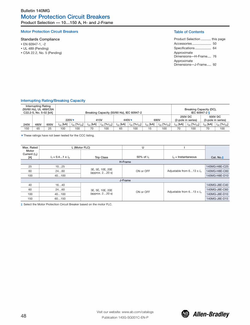
Auxiliary/Alarm Contact (AX/AL)
Description Designation Diagram Frame Size Cat. No.
(1) TU Alarm Contact 250V TU AL C H, J 140G-H-EA1TA
(1) Auxiliary (1) Alarm Contact 250V AX2/AL1 D G, H, I, J 140G-G-EA1R1A
(2) Auxiliary (1) Alarm Contact 250V AX1/AX2/AL1 E G, H, I, J 140G-G-EA2R1A
(3) Auxiliary (1) Alarm Contact 250V AX1/AX2/AX3/AL1 F H, I, J 140G-H-EA3R1A
(3) Auxiliary (2) Alarm Contact 250V AX1/AX2/AX3/AL1/AL2 G H, J 140G-H-EA3R2A
(2) Auxiliary (2) Alarm (1) TU ALContact 250V AX2/AX3/AL1/AL2/TU AL H H, J 140G-H-EA2R2TA
(1) Auxiliary Contact 250V AX2 A G, H, I, J 140G-G-EA1A
(1) Auxiliary Contact 250V or (1) AlarmContact 250V
AX2 AG, H, I, J 140G-G-EA1AU�
AL1 B
(1) Auxiliary Contact 24V AX2 A G, H, I, J 140G-G-EA1J�
(1) TU Alarm Contact 24V TU AL C H, J 140G-H-EA1TJ
(1) Auxiliary (1) Alarm Contact 24V AX2/AL1 D G, H, I, J 140G-G-EA1R1J
(3) Auxilary (1) Alarm Contact, 24V AX1/AX2/AX3/AL1 F H, I, J 140G-H-EA3R1J
(1) Auxilary (1) Alarm Contact, 400V AX2/AL1 D H, J 140G-H-EA1R1B
(2) Auxiliary Contact 400V AX1/AX2 I H, J 140G-H-EA2B
(1) Auxiliary (1) Alarm Contact 250V AX1/AL1 J K, M 140G-K-EA1R1A
(3) Auxiliary (1) Alarm Contact 250V AX1/AX2/AX3/AL1 F K, M 140G-K-EA3R1A
(3) Auxiliary (1) Alarm Contact 24V AX1/AX2/AX3/AL1 F K, M 140G-K-EA3R1J
(1) Auxiliary (1) Alarm Contact 400V AX1/AL1 J K, M 140G-K-EA1R1B
(2) Auxiliary Contact 400V AX1/AX2 I K, M 140G-K-EA2B
(1) Auxiliary (1) Alarm Contact 24V AX2/AL1 D N 140G-N-EA1R1J
(2) Auxiliary Contact 24V AX1/AX2 I N, NS 140G-N-EA2J
(1) Auxiliary (1) Alarm Contact 400V AX2/AL1 D N 140G-N-EA1R1B
(2) Auxiliary Contact 400V AX1/AX2 I N, NS 140G-N-EA2B
(1) TU Alarm Contact 250V TU AL C N, NS 140G-N-EA1TA
(4) Auxiliary Contact 24V AX1/AX2/AX3/AX4 K R 140G-R-EA4J
(4) Auxiliary Contact 400V AX1/AX2/AX3/AX4 K R 140G-R-EA4A
Representative Photo (1) TU Alarm Contact 250V TU AL L R 140G-R-EA1TA
�This contact is supplied with unmarked wires. Contact can function as either an auxiliary or alarm contact, depending on connection method.
Internal Electrical Accessories
Description Page Description PageInternal Electrical AccessoriesAuxiliary/Alarm Contact (AX/AL)................................................ 50 Undervoltage Release (UVR) ...................................................... 53Shunt Trip (SNT)............................................................................... 52 Residual Current Release Module............................................ 53Shunt Close (SNC).......................................................................... 52 Current Transformer for Neutral Current ................................ 54
Mechanical AccessoriesTerminal Lugs.................................................................................... 54 Terminal Covers ............................................................................... 56Extended Terminals........................................................................ 55 Variable Depth Rotary Operating Kits ..................................... 58Spreader Terminals......................................................................... 55 Flex Cable Operators..................................................................... 59Rear Terminals.................................................................................. 56 Direct Rotary Operators................................................................ 60Phase Barriers.................................................................................. 56 Motor Operators.............................................................................. 60
Bulletin 1494V Variable Depth Flange-Mounted Circuit Breaker Operating MechanismComponents ..................................................................................... 61
Additional Accessories................................................................. 62 Replacement Parts......................................................................... 63
Accessories Table of Contents
Auxiliary and alarm contacts are supplied in multiple variations for customer application.
� Auxiliary Contacts (AX) : Indicate ON/OFF status of the MCCB.
� Alarm Contacts (AL): Indicate trip status of the MCCB. Alarm trip can be initiated by pressing the test button on the molded case circuitbreaker, a trip due to overcurrent, short circuit; or trip due to residual current, shunt, or undervoltage release signals.
� Thermal Trip Contacts (TU): Trips only when the MCCB has detected an overcurrent, short-circuit, or protection trip. H- and J-FrameMCCBs have a button to test this feature. Available only for H, J, N, NS, and R frames.
These contacts are installed by removing the MCCB cover and accessing right-side pockets within the breaker with snap-in mountingprovisions. Frames G…M are supplied with pig tail wiring, with each terminal wire marked. Frames N, NS, and R are wired internal to thebreaker and are terminated for connection using a 3-pin quick connector.
Bulletin 140G
Molded Case Circuit Breakers
51Visit our website: www.ab.com/catalogs
Publication 140G-SG001C-EN-P
Accessories
Diagrams
J L
24
AX2
11
11
14
AX1
1412
12
22
22
21
21
31
31
32
AX3
32
24
34
34
41
41
4442
K
AX4
42 44
TU AL
32
34
34
AX3
32
31
31
21
21
22
22
AX2
24
24
24
24
AX2
22
22
21
21
D
H
96
98
98
95
95
AL1
96 16
AL2
15
15
18
18
1616
18
18
15
15
AL2
1624
AX2
11
11
14
AX1
1412
12
22
22
21
21
31
31
32
AX3
32
24
9634
34
AL1
95
95
98
98
96
G
0805
TU AL
0606
05
08
96
98
98
95
95
AL1
96
11
24
AX211
14
AX1
141212
22
22
21
21
31
31
32
AX3
32
24
9634
34
AL1
95
95
98
98
96
F
06
9624
AX2
11
11
14
AX1
1412
12
22
22
21
21
24
AL1
95
95
98
98
96
E
08
05
06
TU AL
0508
C
24
24
AX2
2222
21
21
96
98
98
95
95
AL196
A B
24
AX2
11
11
14
AX1
1412
12
22
22
21
21
24
I
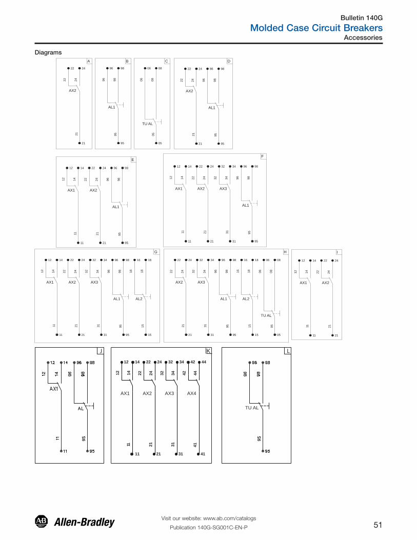
Bulletin 140G
Molded Case Circuit Breakers
52Visit our website: www.ab.com/catalogs
Publication 140G-SG001C-EN-P
Accessories
Shunt Trip (SNT)� Allows for remote tripping of the MCCB by applying control voltage to the shunt trip coil.
� Frames G, H, I, J, K, and M are supplied with pig-tail wiring (each terminal wire is marked).
� Frame N, NS, and R are wired internal to the breaker and terminated for connection using a 3-pin quick connector.
Description Diagram Frame Size Cat. No.
12V DC
C1
C1C2
C2
SNT
SO~+
-~
G, H, I, J
140G-G-SNR
24…30V AC/DC 140G-G-SNJ
48…60V AC/DC 140G-G-SNKY
110…127V AC/110…125V DC 140G-G-SND
220…240V AC/220…250V DC 140G-G-SNA
380…440V AC 140G-G-SNB
Representative Photo 480…525V AC 140G-G-SNC
12V DC
K, M
140G-K-SNR
24…30V AC/DC 140G-K-SNJ
48…60V AC/DC 140G-K-SNKY
110…127V AC/110…125V DC 140G-K-SND
220…240V AC/220…250V DC 140G-K-SNA
380…440V AC 140G-K-SNB
Representative Photo 480…525V AC 140G-K-SNC
24V AC/DC
N, NS
140G-N-SNJ
48V AC/DC 140G-N-SNKY
110…120V AC/DC 140G-N-SND
220…240V AC/DC 140G-N-SNA
380…400V AC 140G-N-SNB
24V DC
R
140G-R-SNJ
48V AC/DC 140G-R-SNKY
110…120V AC/DC 140G-R-SND
220…240V AC/DC 140G-R-SNA
Representative Photo 380…400V AC/DC 140G-R-SNB
� For use with motorized versions of the NS- and R-Frame MCCB.
� Allows for remote closing of the MCCB when the spring motor is charged.
The shunt close unit is wired internal to the MCCB and terminated for connection using a 3-pin quick connect.
Description Diagram Frame Size Cat. No.
24V AC/DC
SNC
C2
C2
C1
C1
-~
~+
SO
NS
140G-NS-SNCJ
48V AC/DC 140G-NS-SNCKY
110…120V AC/DC 140G-NS-SNCD
220…240V AC/DC 140G-NS-SNCA
380…400V AC 140G-NS-SNCB
24V DC
R
140G-R-SNCJ
48V AC/DC 140G-R-SNCKY
110…120V AC/DC 140G-R-SNCD
220…240V AC/DC 140G-R-SNCA
Representative Photo 380…400V AC 140G-R-SNCB
Shunt Close (SNC)
Bulletin 140G
Molded Case Circuit Breakers
53Visit our website: www.ab.com/catalogs
Publication 140G-SG001C-EN-P
Accessories
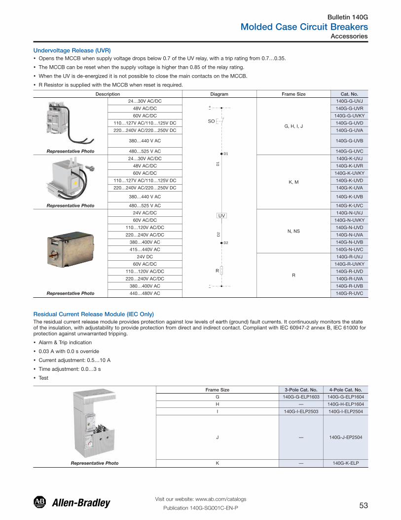
Residual Current Release Module (IEC Only)
Frame Size 3-Pole Cat. No. 4-Pole Cat. No.
G 140G-G-ELP1603 140G-G-ELP1604
H — 140G-H-ELP1604
I 140G-I-ELP2503 140G-I-ELP2504
J — 140G-J-EP2504
Representative Photo K — 140G-K-ELP
Undervoltage Release (UVR)� Opens the MCCB when supply voltage drops below 0.7 of the UV relay, with a trip rating from 0.7…0.35.
� The MCCB can be reset when the supply voltage is higher than 0.85 of the relay rating.
� When the UV is de-energized it is not possible to close the main contacts on the MCCB.
� R Resistor is supplied with the MCCB when reset is required.
Description Diagram Frame Size Cat. No.
24…30V AC/DC
R
~-
UVD
2
D2
D1
D1
+~
SOG, H, I, J
140G-G-UVJ
48V AC/DC 140G-G-UVR
60V AC/DC 140G-G-UVKY
110…127V AC/110…125V DC 140G-G-UVD
220…240V AC/220…250V DC 140G-G-UVA
380…440 V AC 140G-G-UVB
Representative Photo 480…525 V AC 140G-G-UVC
24…30V AC/DC
K, M
140G-K-UVJ
48V AC/DC 140G-K-UVR
60V AC/DC 140G-K-UVKY
110…127V AC/110…125V DC 140G-K-UVD
220…240V AC/220…250V DC 140G-K-UVA
380…440 V AC 140G-K-UVB
Representative Photo 480…525 V AC 140G-K-UVC
24V AC/DC
N, NS
140G-N-UVJ
60V AC/DC 140G-N-UVKY
110…120V AC/DC 140G-N-UVD
220…240V AC/DC 140G-N-UVA
380…400V AC 140G-N-UVB
415…440V AC 140G-N-UVC
24V DC
R
140G-R-UVJ
60V AC/DC 140G-R-UVKY
110…120V AC/DC 140G-R-UVD
220…240V AC/DC 140G-R-UVA
380…400V AC 140G-R-UVB
Representative Photo 440…480V AC 140G-R-UVC
The residual current release module provides protection against low levels of earth (ground) fault currents. It continuously monitors the stateof the insulation, with adjustability to provide protection from direct and indirect contact. Compliant with IEC 60947-2 annex B, IEC 61000 forprotection against unwarranted tripping.
� Alarm & Trip indication
� 0.03 A with 0.0 s override
� Current adjustment: 0.5…10 A
� Time adjustment: 0.0…3 s
� Test
Bulletin 140G
Molded Case Circuit Breakers
54Visit our website: www.ab.com/catalogs
Publication 140G-SG001C-EN-P
Accessories
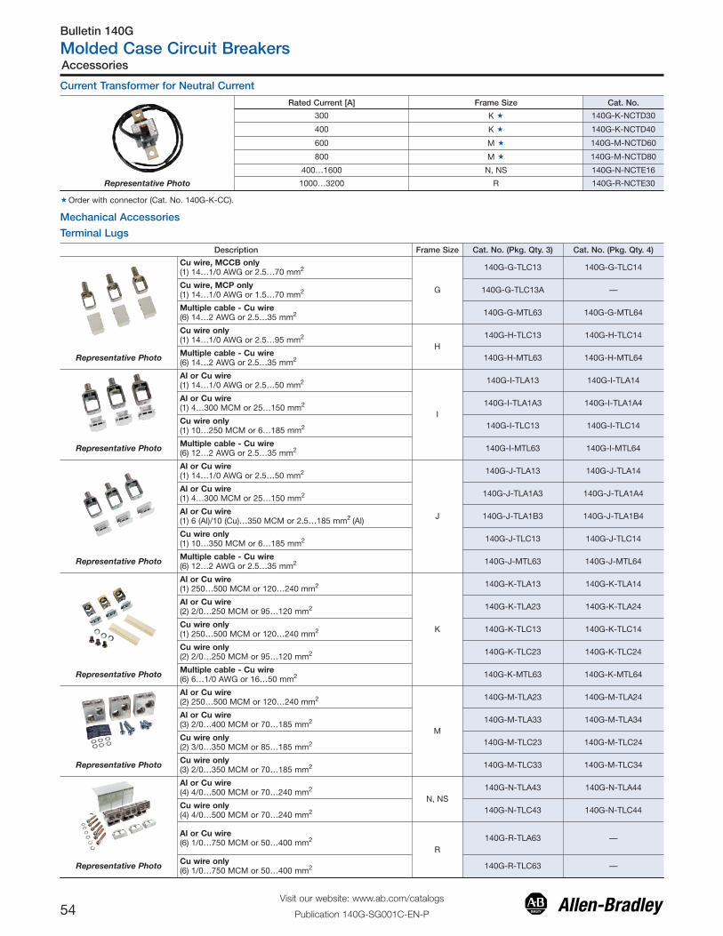
Terminal Lugs
Current Transformer for Neutral Current
Rated Current [A] Frame Size Cat. No.
300 K � 140G-K-NCTD30
400 K � 140G-K-NCTD40
600 M � 140G-M-NCTD60
800 M � 140G-M-NCTD80
400…1600 N, NS 140G-N-NCTE16
Representative Photo 1000…3200 R 140G-R-NCTE30
�Order with connector (Cat. No. 140G-K-CC).
Mechanical Accessories
Description Frame Size Cat. No. (Pkg. Qty. 3) Cat. No. (Pkg. Qty. 4)
Cu wire, MCCB only(1) 14…1/0 AWG or 2.5…70 mm2
G
140G-G-TLC13 140G-G-TLC14
Cu wire, MCP only(1) 14…1/0 AWG or 1.5…70 mm2 140G-G-TLC13A —
Multiple cable - Cu wire(6) 14…2 AWG or 2.5…35 mm2 140G-G-MTL63 140G-G-MTL64
Cu wire only(1) 14…1/0 AWG or 2.5…95 mm2
H140G-H-TLC13 140G-H-TLC14
Representative Photo Multiple cable - Cu wire(6) 14…2 AWG or 2.5…35 mm2 140G-H-MTL63 140G-H-MTL64
Al or Cu wire(1) 14…1/0 AWG or 2.5…50 mm2
I
140G-I-TLA13 140G-I-TLA14
Al or Cu wire(1) 4…300 MCM or 25…150 mm2 140G-I-TLA1A3 140G-I-TLA1A4
Cu wire only(1) 10…250 MCM or 6…185 mm2 140G-I-TLC13 140G-I-TLC14
Representative Photo Multiple cable - Cu wire(6) 12…2 AWG or 2.5…35 mm2 140G-I-MTL63 140G-I-MTL64
Al or Cu wire(1) 14…1/0 AWG or 2.5…50 mm2
J
140G-J-TLA13 140G-J-TLA14
Al or Cu wire(1) 4…300 MCM or 25…150 mm2 140G-J-TLA1A3 140G-J-TLA1A4
Al or Cu wire(1) 6 (Al)/10 (Cu)…350 MCM or 2.5…185 mm2 (Al) 140G-J-TLA1B3 140G-J-TLA1B4
Cu wire only(1) 10…350 MCM or 6…185 mm2 140G-J-TLC13 140G-J-TLC14
Representative Photo Multiple cable - Cu wire(6) 12…2 AWG or 2.5…35 mm2 140G-J-MTL63 140G-J-MTL64
Al or Cu wire(1) 250…500 MCM or 120…240 mm2
K
140G-K-TLA13 140G-K-TLA14
Al or Cu wire(2) 2/0…250 MCM or 95…120 mm2 140G-K-TLA23 140G-K-TLA24
Cu wire only(1) 250…500 MCM or 120…240 mm2 140G-K-TLC13 140G-K-TLC14
Cu wire only(2) 2/0…250 MCM or 95…120 mm2 140G-K-TLC23 140G-K-TLC24
Representative Photo Multiple cable - Cu wire(6) 6…1/0 AWG or 16…50 mm2 140G-K-MTL63 140G-K-MTL64
Al or Cu wire(2) 250…500 MCM or 120…240 mm2
M
140G-M-TLA23 140G-M-TLA24
Al or Cu wire(3) 2/0…400 MCM or 70…185 mm2 140G-M-TLA33 140G-M-TLA34
Cu wire only (2) 3/0…350 MCM or 85…185 mm2 140G-M-TLC23 140G-M-TLC24
Representative Photo Cu wire only (3) 2/0…350 MCM or 70…185 mm2 140G-M-TLC33 140G-M-TLC34
Al or Cu wire(4) 4/0…500 MCM or 70…240 mm2
N, NS140G-N-TLA43 140G-N-TLA44
Cu wire only (4) 4/0…500 MCM or 70…240 mm2 140G-N-TLC43 140G-N-TLC44
Al or Cu wire(6) 1/0…750 MCM or 50…400 mm2
R140G-R-TLA63 —
Representative Photo Cu wire only (6) 1/0…750 MCM or 50…400 mm2 140G-R-TLC63 —
Bulletin 140G
Molded Case Circuit Breakers
55Visit our website: www.ab.com/catalogs
Publication 140G-SG001C-EN-P
Accessories
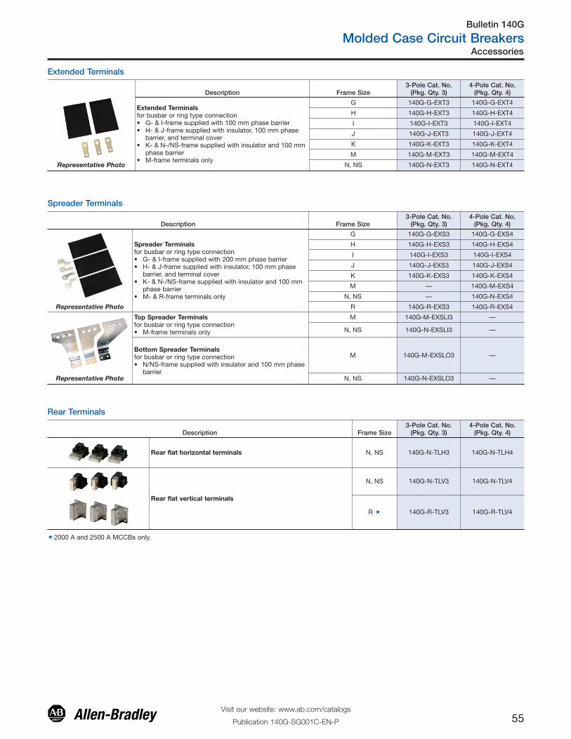
Extended Terminals
Description Frame Size3-Pole Cat. No.
(Pkg. Qty. 3)4-Pole Cat. No.
(Pkg. Qty. 4)
Extended Terminalsfor busbar or ring type connection• G- & I-frame supplied with 100 mm phase barrier• H- & J-frame supplied with insulator, 100 mm phase
barrier, and terminal cover• K- & N-/NS-frame supplied with insulator and 100 mm
phase barrier• M-frame terminals only
G 140G-G-EXT3 140G-G-EXT4
H 140G-H-EXT3 140G-H-EXT4
I 140G-I-EXT3 140G-I-EXT4
J 140G-J-EXT3 140G-J-EXT4
K 140G-K-EXT3 140G-K-EXT4
M 140G-M-EXT3 140G-M-EXT4
Representative Photo N, NS 140G-N-EXT3 140G-N-EXT4
Spreader Terminals
Description Frame Size3-Pole Cat. No.
(Pkg. Qty. 3)4-Pole Cat. No.
(Pkg. Qty. 4)
Spreader Terminalsfor busbar or ring type connection• G- & I-frame supplied with 200 mm phase barrier• H- & J-frame supplied with insulator, 100 mm phase
barrier, and terminal cover• K- & N-/NS-frame supplied with insulator and 100 mm
phase barrier• M- & R-frame terminals only
G 140G-G-EXS3 140G-G-EXS4
H 140G-H-EXS3 140G-H-EXS4
I 140G-I-EXS3 140G-I-EXS4
J 140G-J-EXS3 140G-J-EXS4
K 140G-K-EXS3 140G-K-EXS4
M — 140G-M-EXS4
N, NS — 140G-N-EXS4
Representative Photo R 140G-R-EXS3 140G-R-EXS4
Top Spreader Terminalsfor busbar or ring type connection• M-frame terminals only
M 140G-M-EXSLI3 —
N, NS 140G-N-EXSLI3 —
Bottom Spreader Terminalsfor busbar or ring type connection• N/NS-frame supplied with insulator and 100 mm phase
barrier
M 140G-M-EXSLO3 —
Representative Photo N, NS 140G-N-EXSLO3 —
Rear Terminals
Description Frame Size3-Pole Cat. No.
(Pkg. Qty. 3)4-Pole Cat. No.
(Pkg. Qty. 4)
Rear flat horizontal terminals N, NS 140G-N-TLH3 140G-N-TLH4
Rear flat vertical terminals
N, NS 140G-N-TLV3 140G-N-TLV4
R � 140G-R-TLV3 140G-R-TLV4
�2000 A and 2500 A MCCBs only.
Bulletin 140G
Molded Case Circuit Breakers
56Visit our website: www.ab.com/catalogs
Publication 140G-SG001C-EN-P
Accessories
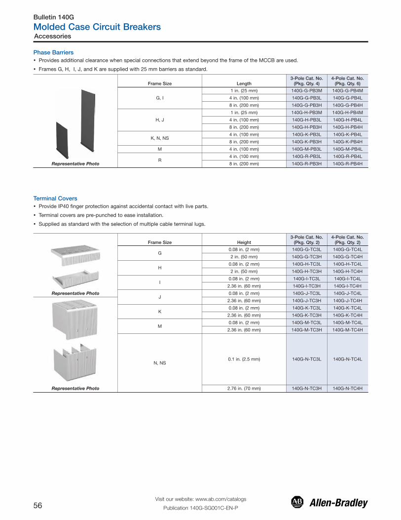
Phase Barriers� Provides additional clearance when special connections that extend beyond the frame of the MCCB are used.
� Frames G, H, I, J, and K are supplied with 25 mm barriers as standard.
Frame Size Length3-Pole Cat. No.
(Pkg. Qty. 4)4-Pole Cat. No.
(Pkg. Qty. 6)
G, I
1 in. (25 mm) 140G-G-PB3M 140G-G-PB4M
4 in. (100 mm) 140G-G-PB3L 140G-G-PB4L
8 in. (200 mm) 140G-G-PB3H 140G-G-PB4H
H, J
1 in. (25 mm) 140G-H-PB3M 140G-H-PB4M
4 in. (100 mm) 140G-H-PB3L 140G-H-PB4L
8 in. (200 mm) 140G-H-PB3H 140G-H-PB4H
K, N, NS4 in. (100 mm) 140G-K-PB3L 140G-K-PB4L
8 in. (200 mm) 140G-K-PB3H 140G-K-PB4H
M 4 in. (100 mm) 140G-M-PB3L 140G-M-PB4L
R4 in. (100 mm) 140G-R-PB3L 140G-R-PB4L
Representative Photo 8 in. (200 mm) 140G-R-PB3H 140G-R-PB4H
Terminal Covers
Frame Size Height3-Pole Cat. No.
(Pkg. Qty. 2)4-Pole Cat. No.
(Pkg. Qty. 2)
G0.08 in. (2 mm) 140G-G-TC3L 140G-G-TC4L
2 in. (50 mm) 140G-G-TC3H 140G-G-TC4H
H0.08 in. (2 mm) 140G-H-TC3L 140G-H-TC4L
2 in. (50 mm) 140G-H-TC3H 140G-H-TC4H
I0.08 in. (2 mm) 140G-I-TC3L 140G-I-TC4L
2.36 in. (60 mm) 140G-I-TC3H 140G-I-TC4H
Representative PhotoJ
0.08 in. (2 mm) 140G-J-TC3L 140G-J-TC4L
2.36 in. (60 mm) 140G-J-TC3H 140G-J-TC4H
K0.08 in. (2 mm) 140G-K-TC3L 140G-K-TC4L
2.36 in. (60 mm) 140G-K-TC3H 140G-K-TC4H
M0.08 in. (2 mm) 140G-M-TC3L 140G-M-TC4L
2.36 in. (60 mm) 140G-M-TC3H 140G-M-TC4H
N, NS0.1 in. (2.5 mm) 140G-N-TC3L 140G-N-TC4L
Representative Photo 2.76 in. (70 mm) 140G-N-TC3H 140G-N-TC4H
� Provide IP40 finger protection against accidental contact with live parts.
� Terminal covers are pre-punched to ease installation.
� Supplied as standard with the selection of multiple cable terminal lugs.

Bulletin 140G
Molded Case Circuit Breakers
57Visit our website: www.ab.com/catalogs
Publication 140G-SG001C-EN-P
Accessories
Variable Depth Rotary Operating Kits
Frame Size Handle Color Shaft Length Cat. No.
G, I
Black12 in. (30.48 mm)
140G-G-RVM12B
Red/Yellow 140G-G-RVM12R
Black21 in. (53.34 mm)
140G-G-RVM21B
Red/yellow 140G-G-RVM21R
H, J
Black12 in. (30.48 mm)
140G-H-RVM12B
Red/yellow 140G-H-RVM12R
Black21 in. (53.34 mm)
140G-H-RVM21B
Representative Photo Red/yellow 140G-H-RVM21R
K
Black12.6 in. (320 mm)
140G-K-RVM12B
Red/yellow 140G-K-RVM12R
Black22.8 in. (580 mm)
140G-K-RVM21B
Red/yellow 140G-K-RVM21R
M
Black12.6 in. (320 mm)
140G-M-RVM12B
Red/yellow 140G-M-RVM12R
Black22.8 in. (580 mm)
140G-M-RVM21B
Red/yellow 140G-M-RVM21R
N
Black12.6 in. (320 mm)
140G-N-RVM12B
Red/yellow 140G-N-RVM12R
Black22.8 in. (580 mm)
140G-N-RVM21B
Representative Photo Red/yellow 140G-N-RVM21R
Frame Size Handle Color Shaft Length Cat. No.
G, I
Black12 in. (30.48 mm)
140G-G-NVM12B
Red/yellow 140G-G-NVM12R
Black21 in. (53.34 mm)
140G-G-NVM21B
Red/yellow 140G-G-NVM21R
H, J
Black12 in. (30.48 mm)
140G-H-NVM12B
Red/yellow 140G-H-NVM12R
Black21 in. (53.34 mm)
140G-H-NVM21B
Representative Photo Red/yellow 140G-H-NVM21R
K
Black12.6 in. (320 mm)
140G-K-NVM12B
Red/yellow 140G-K-NVM12R
Black22.8 in. (580 mm)
140G-K-NVM21B
Red/yellow 140G-K-NVM21R
M
Black12.6 in. (320 mm)
140G-M-NVM12B
Red/yellow 140G-M-NVM12R
Black22.8 in. (580 mm)
140G-M-NVM21B
Red/yellow 140G-M-NVM21R
N
Black12.6 in. (320 mm)
140G-N-NVM12B
Red/yellow 140G-N-NVM12R
Black22.8 in. (580 mm)
140G-N-NVM21B
Representative Photo Red/yellow 140G-N-NVM21R
Rotary, Variable Depth Operators• Supplied with external handle, operating shaft, and MCCB mounted operating mechanism.
• Refer to page 56 to select as components.
• Frames G, H, I, and J use a Bul. 140U P-style handle.
• Frames K, M, and N use a Bul. 140U medium style handle.
Rotary, Variable Depth Operators with Internal NFPA 79 Operating Handle• Supplied with external handle, NFPA handle with operating shaft, support bracket, and MCCB mounted operating mechanism.
• Refer to page 58 to select as components.
• Frames G, H, I, and J use a Bul. 140U P-style handle.
• Frames K, M, and N use a Bul. 140U medium style handle.

Bulletin 140G
Molded Case Circuit Breakers
58Visit our website: www.ab.com/catalogs
Publication 140G-SG001C-EN-P
Accessories
Variable Depth Rotary Components
Description Handle Color Frame Size Cat. No.
• P-style handle for G, H, I, andJ frames
• Medium handles for K, M, andN frames
• Rated 3/3R/4/4X/12• Accepts 3 padlocks
Black/GreyG, H, I, J
140U-PB
Red/Yellow 140U-PY
Black/GreyK, M, N
140U-HM4
Representative Photo Red/Yellow 140U-HM4E
Description Shaft Length Frame Size Cat. No.
Extension Shaft
12 in. (305 mm)G, H, I, J
194R-S1
21 in. (533 mm) 194R-S2
12 in. (305 mm)K, M, N
140U-R5
Representative Photo 21 in. (533 mm) 140U-R6
Description Shaft Length Frame Size Cat. No.
NFPA 79 internal operatinghandle with shaftInternal handle permits operationof the molded case circuit breakerwhen the door is open incompliance with NFPA 79.
12 in. (305 mm)G, H, I, J
140G-N1
21 in. (533 mm) 140G-N2
12 in. (305 mm)K, M, N
140G-N7
Representative Photo 21 in. (533 mm) 140G-N8
Description Frame Size Cat. No.
Rotary, Variable Depth OperatingMechanism• Direct molded case circuit breaker mount• G, H, I, and J frame use 194R-S1 or 194R-
S2 shafts (140G-N1 or 140G-N2 NFPA)• K, M, and N frames use 194R-R7 or 194R-
R8 shafts (140G-R7 or 140G-R8 NFPA)• Shaft secured with set screw or cotter pin
G, I 140G-G-RMX
H, J 140G-H-RMX
K 140G-K-RMX
M 140G-M-RMX
Representative Photo N 140G-N-RMX
Description Frame Size Cat. No.
Support BracketSupplied as standard with NFPA variable depth operator kits
G, H, I, J 140G-G-OSB
K 140G-K-OSB
M 140G-M-OSB
N 140G-N-OSB
Auxiliary Contacts for Handle Mechanism MountingSuitable for:
� 140G-G-RMB, -RMY, RMX
� 140G-H-RMB, -RMY, RMX
� 140G-K-RMB, -RMY, RMX
� 140G-M-RMB, -RMY, RMX
Description Pkg. Qty Frame Size Cat. No.
Early Make Handle Auxiliary ContactOpen 400V 2
G, H, I, J
140G-G-EAM1B
Early Break Handle AuxiliaryContactClose 400V
2 140G-G-EAB1B
Early Make Handle Auxiliary ContactClose 250V 2
K 140G-K-EAM1A
Representative Photo M 140G-M-EAM1A
Bulletin 140G
Molded Case Circuit Breakers
59Visit our website: www.ab.com/catalogs
Publication 140G-SG001C-EN-P
Accessories
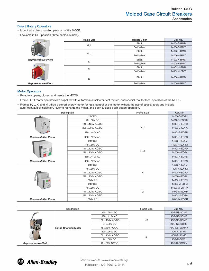
Description Frame Size Cat. No.
24V DC
G, I
140G-G-EOPJ
48…60V DC 140G-G-EOPKY
110…125V AC/DC 140G-G-EOPD
220…250V AC/DC 140G-G-EOPA
380…440V AC 140G-G-EOPB
Representative Photo 480…525V AC 140G-G-EOPC
24V DC
H, J
140G-H-EOPJ
48…60V DC 140G-H-EOPKY
110…125V AC/DC 140G-H-EOPD
220…250V AC/DC 140G-H-EOPA
380…440V AC 140G-H-EOPB
Representative Photo 480…525V AC 140G-H-EOPC
24V DC
K
140G-K-EOPJ
48…60V DC 140G-K-EOPKY
110…125V AC/DC 140G-K-EOPD
220…250V AC/DC 140G-K-EOPA
380V AC 140G-K-EOPB
24V DC
M
140G-M-EOPJ
48…60V DC 140G-M-EOPKY
110…125V AC/DC 140G-M-EOPD
220…250V AC/DC 140G-M-EOPA
Representative Photo 380V AC 140G-M-EOPB
Direct Rotary Operators� Mount with direct handle operation of the MCCB.
� Lockable in OFF position (three padlocks max.).
Description Frame Size Cat. No.
Spring Charging Motor
220…250V DC
NS
140G-NS-SCMA
380…415V AC 140G-NS-SCMB
100…130V AC/DC 140G-NS-SCMD
24…30V DC 140G-NS-SCMJ
48…60V AC/DC 140G-NS-SCMKY
220…250V DC
R
140G-R-SCMA
100…130V AC/DC 140G-R-SCMD
24…30V DC 140G-R-SCMJ
Representative Photo 48…60V AC/DC 140G-R-SCMKY
Frame Size Handle Color Cat. No.
G, IBlack 140G-G-RMB
Red/yellow 140G-G-RMY
H, JBlack 140G-H-RMB
Red/yellow 140G-H-RMY
Representative PhotoK
Black 140G-K-RMB
Red/yellow 140G-K-RMY
MBlack 140G-M-RMB
Red/yellow 140G-M-RMY
NBlack 140G-N-RMB
Representative Photo Red/yellow 140G-N-RMY
� Remotely opens, closes, and resets the MCCB.
� Frame G & I motor operators are supplied with auto/manual selector, test feature, and special tool for local operation of the MCCB.
� Frames H, J, K, and M utilize a stored energy motor for local control of the motor without the use of special tools and includeauto/manual/lock selection, lever to recharge the motor, and open & close push button operation.
Motor Operators
Bulletin 140G
Molded Case Circuit Breakers
60Visit our website: www.ab.com/catalogs
Publication 140G-SG001C-EN-P
Accessories
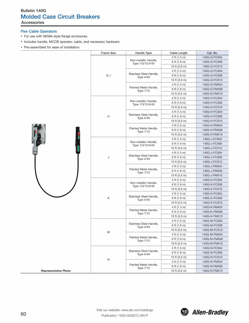
Flex Cable Operators� For use with NEMA-style flange enclosures.
� Includes handle, MCCB operator, cable, and necessary hardware.
� Pre-assembled for ease of installation.
Frame Size Handle Type Cable Length Cat. No.
G, I
Non-metallic Handle,Type 1/3/12/4/4X
4 ft (1.3 m) 140G-G-FCX04
6 ft (1.9 m) 140G-G-FCX06
10 ft (3.0 m) 140G-G-FCX10
Stainless Steel Handle,Type 4/4X
4 ft (1.3 m) 140G-G-FCS04
6 ft (1.9 m) 140G-G-FCS06
10 ft (3.0 m) 140G-G-FCS10
Painted Metal Handle,Type 1/12
4 ft (1.3 m) 140G-G-FMX04
6 ft (1.9 m) 140G-G-FMX06
10 ft (3.0 m) 140G-G-FMX10
H
Non-metallic Handle,Type 1/3/12/4/4X
4 ft (1.3 m) 140G-H-FCX04
6 ft (1.9 m) 140G-H-FCX06
10 ft (3.0 m) 140G-H-FCX10
Stainless Steel Handle,Type 4/4X
4 ft (1.3 m) 140G-H-FCS04
6 ft (1.9 m) 140G-H-FCS06
10 ft (3.0 m) 140G-H-FCS10
Painted Metal Handle,Type 1/12
4 ft (1.3 m) 140G-H-FMX04
6 ft (1.9 m) 140G-H-FMX06
10 ft (3.0 m) 140G-H-FMX10
J
Non-metallic Handle,Type 1/3/12/4/4X
4 ft (1.3 m) 140G-J-FCX04
6 ft (1.9 m) 140G-J-FCX06
10 ft (3.0 m) 140G-J-FCX10
Stainless Steel Handle,Type 4/4X
4 ft (1.3 m) 140G-J-FCS04
6 ft (1.9 m) 140G-J-FCS06
10 ft (3.0 m) 140G-J-FCS10
Painted Metal Handle,Type 1/12
4 ft (1.3 m) 140G-J-FMX04
6 ft (1.9 m) 140G-J-FMX06
10 ft (3.0 m) 140G-J-FMX10
K
Non-metallic Handle,Type 1/3/12/4/4X
4 ft (1.3 m) 140G-K-FCX04
6 ft (1.9 m) 140G-K-FCX06
10 ft (3.0 m) 140G-K-FCX10
Stainless Steel Handle,Type 4/4X
4 ft (1.3 m) 140G-K-FCS04
6 ft (1.9 m) 140G-K-FCS06
10 ft (3.0 m) 140G-K-FCS10
Painted Metal Handle,Type 1/12
4 ft (1.3 m) 140G-K-FMX04
6 ft (1.9 m) 140G-K-FMX06
10 ft (3.0 m) 140G-K-FMX10
M
Stainless Steel Handle,Type 4/4X
4 ft (1.3 m) 140G-M-FCS04
6 ft (1.9 m) 140G-M-FCS06
10 ft (3.0 m) 140G-M-FCS10
Painted Metal Handle,Type 1/12
4 ft (1.3 m) 140G-M-FMX04
6 ft (1.9 m) 140G-M-FMX06
10 ft (3.0 m) 140G-M-FMX10
N
Stainless Steel Handle,Type 4/4X
4 ft (1.3 m) 140G-N-FCS04
6 ft (1.9 m) 140G-N-FCS06
10 ft (3.0 m) 140G-N-FCS10
Painted Metal Handle,Type 1/12
4 ft (1.3 m) 140G-N-FMX04
6 ft (1.9 m) 140G-N-FMX06
Representative Photo 10 ft (3.0 m) 140G-N-FMX10

Bulletin 140G
Molded Case Circuit Breakers
61Visit our website: www.ab.com/catalogs
Publication 140G-SG001C-EN-P
Accessories
Bulletin 1494V Variable Depth Flange-Mounted Circuit Breaker Operating Mechanism
Components
Circuit Breaker Operating MechanismThe mechanism listed must be combined with a connecting rod, operating handle, and a circuit breaker (supplied bycustomer) to obtain a functional device.
3-Pole Circuit Breaker� Operating Mechanism
Brand Frame Size [A] Frame Designation Cat. No.
Allen-Bradley 125, 225, 250 140G-G, H, I, J 1494V-M70
Allen-Bradley 400 140G-K 1494V-M71
Allen-Bradley 800, 1200 140G-M, N 1494V-M72
�Circuit breakers to be provided by customer.
Connecting RodsApproximate dimensions are in inches (millimeters). Approximate dimensions are not intended for manufacturing purposes.
Circuit BreakerFrame Size [A]
Enclosure Depth
Cat. No.Minimum Maximum
125, 150, 250, 400, 600, 800, 12006-3/4 (172) 9-1/8 (232) 1494V-RA3
6-3/4 (172) 21-5/8 (549) 1494V-RA4
Operating Handle
Handle Type DescriptionCircuit BreakerFrame Size [A]
Operating Handle
Cat. No.
Type 1, 3R, 4, 4X, 12 Nonmetallic 125, 150, 250, 400 1494F-P1
Type 1, 3R, 4, 12 Painted Metal 125, 150, 250, 400 1494F-M1
Type 4, 4X Stainless Steel 125, 150, 250, 400 1494F-S1
Type 1, 3R, 4, 12 Painted Metal 800, 1200 1494F-M2
Type 4, 4X Stainless Steel 800, 1200 1494F-S2
Auxiliary Contacts
Description For Use With Contact Type Cat. No.
Auxiliary Contact Kit for CircuitBreakers(includes contacts and adapter)
125…1200 A Allen-Bradley Bul. 140GCircuit Breakers
1 N.O. 1495-N85
1 N.C. 1495-N86
Bulletin 140G
Molded Case Circuit Breakers
62Visit our website: www.ab.com/catalogs
Publication 140G-SG001C-EN-P
Accessories
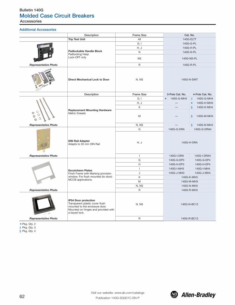
Additional Accessories
Description Frame Size Cat. No.
Trip Test Unit All 140G-ELTT
Padlockable Handle BlockPadlocking HaspLock-OFF only
G, I 140G-G-PL
H, J 140G-H-PL
N 140G-N-PL
NS 140G-NS-PL
Representative Photo R 140G-R-PL
Direct Mechanical Lock to Door N, NS 140G-N-SINT
Description Frame Size 3-Pole Cat. No. 4-Pole Cat. No.
Replacement Mounting HardwareMetric threads
G, I � 140G-G-MH3 ‡ 140G-G-MH4
H, J — � 140G-H-MH4
K — § 140G-K-MH4
M — § 140G-M-MH4
Representative Photo N, NS — § 140G-N-MH4
DIN Rail AdapterAdapts to 35 mm DIN Rail
G 140G-G-DRA 140G-G-DRA4
H, J 140G-H-DRA
Representative Photo I 140G-I-DRA 140G-I-DRA4
Escutcheon PlatesFinsh Frame with Marking provisionwindow. For flush mounted (to door)MCCB applications.
G 140G-G-EP3 140G-G-EP4
H 140G-H-EP3 140G-H-EP4
I 140G-I-MH3 140G-I-MH4
J 140G-J-MH3 140G-J-MH4
K 140G-K-MH3
M 140G-M-MH3
N, NS 140G-N-MH3
Representative Photo R 140G-R-MH3
IP54 Door protectionTransparent plastic cover flushmounted to the enclosure door.Mounted on hinges and provided witha keyed lock.
N, NS 140G-N-BC12
Representative Photo R 140G-R-BC12
�Pkg. Qty. 2‡ Pkg. Qty. 3§ Pkg. Qty. 4
Bulletin 140G
Molded Case Circuit Breakers
63Visit our website: www.ab.com/catalogs
Publication 140G-SG001C-EN-P
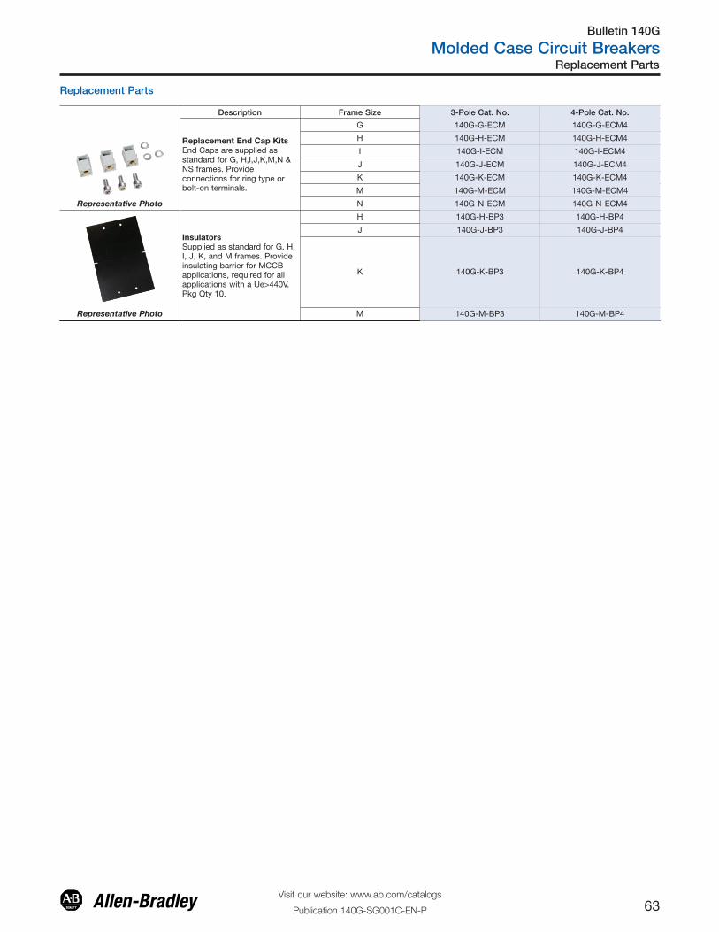
Replacement Parts
Replacement Parts
Description Frame Size 3-Pole Cat. No. 4-Pole Cat. No.
Replacement End Cap KitsEnd Caps are supplied asstandard for G, H,I,J,K,M,N &NS frames. Provideconnections for ring type orbolt-on terminals.
G 140G-G-ECM 140G-G-ECM4
H 140G-H-ECM 140G-H-ECM4
I 140G-I-ECM 140G-I-ECM4
J 140G-J-ECM 140G-J-ECM4
K 140G-K-ECM 140G-K-ECM4
M 140G-M-ECM 140G-M-ECM4
Representative Photo N 140G-N-ECM 140G-N-ECM4
InsulatorsSupplied as standard for G, H,I, J, K, and M frames. Provideinsulating barrier for MCCBapplications, required for allapplications with a Ue>440V.Pkg Qty 10.
H 140G-H-BP3 140G-H-BP4
J 140G-J-BP3 140G-J-BP4
K 140G-K-BP3 140G-K-BP4
Representative Photo M 140G-M-BP3 140G-M-BP4
Bulletin 140G
Molded Case Circuit Breakers
64Visit our website: www.ab.com/catalogs
Publication 140G-SG001C-EN-P
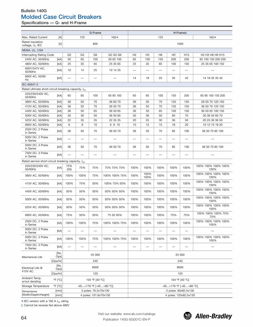
Specifications — G- and H-Frame
G-Frame H-Frame‡
Max. Rated Current [A] 125 160� 125 160�
Rated insulationvoltage, Ui, IEC [V] 800 1000
NEMA, UL, CSA
Interrupting Rating Code G2 G3 G6 G2 G3 G6 H2 H3 H6 H0 H15 H2 H3 H6 H0 H15
240V AC, 50/60Hz [kA] 50 65 100 50 65 100 65 100 150 200 200 65 100 150 200 200
480V AC, 50/60Hz [kA] 25 35 65 25 35 65 25 35 65 100 150 25 35 65 100 150
600Y/347V AC,50/60Hz [kA] 10 14 25 10 14 25 — — — — — —
600V AC, 50/60Hz [kA] — — — — 14 18 25 35 42 14 18 35 35 42
IEC 60947-2
Rated ultimate short-circuit breaking capacity, Icu
220/230/240V AC,50/60Hz [kA] 65 85 100 65 85 100 65 85 100 150 200 65 85 100 150 200
380V AC, 50/60Hz [kA] 36 50 70 36 60 70 36 50 70 120 150 26 50 70 120 150
415V AC, 50/60Hz [kA] 36 50 70 36 50 70 36 50 70 120 150 36 50 70 120 150
440V AC, 50/60Hz [kA] 36 50 65 36 50 65 36 50 65 100 150 36 50 65 100 150
500V AC, 50/60Hz [kA] 30 36 50 36 50 65 30 36 50 60 70 30 36 50 60 70
525V AC, 50/60Hz [kA] 22 35 35 22 35 35 20 25 30 36 50 20 25 30 36 50
690V AC, 50/60Hz [kA] 6 8 10 6 8 10 10 12 15 18 20 10 12 15 18 20
250V DC, 2 Polesin Series [kA] 36 50 70 36 50 70 36 50 70 85 100 36 50 70 85 100
500V DC, 2 Polesin Series [kA] — — — — — — — — — —
500V DC, 3 Polesin Series [kA] 36 50 70 36 50 70 36 50 70 85 100 36 50 70 85 100
750V DC, 3 Polesin Series [kA] — — — — — — — — — —
Rated service short-circuit breaking capacity, Ics
220/230/240V AC,50/60Hz [kA] 75%
(50) 75% 75% 75% 75% 75% 100% 100% 100% 100% 100% 100% 100% 100% 100%100%
380V AC, 50/60Hz [kA] 100% 100% 75% 100% 100% 75% 100% 100%100% 100% 100% 100% 100% 100% 100% 100%
100%
415V AC, 50/60Hz [kA] 100% 75% 50% 100% 75% 50% 100% 100% 100% 100% 100% 100% 100% 100% 100%100%
440V AC, 50/60Hz [kA] 50% 50% 50% 50% 50% 50% 100% 100% 100% 100% 100% 100% 100% 100% 100%100%
500V AC, 50/60Hz [kA] 50% 50% 50% 50% 50% 50% 100% 100% 100% 100% 100% 100% 100% 100% 100%100%
525V AC, 50/60Hz [kA] 50% 50% 50% 50% 50% 50% 100% 100% 100% 100% 100% 100% 100% 100% 100%100%
690V AC, 50/60Hz [kA] 75% 50% 50% 75 50 50% 100% 100% 100% 75% 75% 100% 100% 100% 75%75%
250V DC, 2 Polesin Series [kA] 100% 100% 75% 100% 100% 75% 100% 100% 100% 100% 100% 100% 100% 100% 100%
100%
500V DC, 2 Polesin Series [kA] — — — — — — — — — —
500V DC, 3 Polesin Series [kA] 100% 100% 75% 100% 100% 75% 100% 100% 100% 100% 100% 100% 100% 100% 100%
100%
750V DC, 3 Polesin Series [kA] — — — — — — — — — —
Mechanical Life [No.
Ops] 25 000 25 000
[Ops/hr] 240 240
Electrical Life @415V AC
[No.Ops] 8000 8000
[Ops/hr] 120 120
Ambient Temp.w/out derating ºF [ºC] 104 ºF [40 ºC] 104 ºF [40 ºC]
Storage Temperature ºF [ºC] -40...+176 ºF [-40…+80 ºC] -40...+176 ºF [-40…+80 ºC]
Dimensions[Width/Depth/Height]
[mm] 3 poles: 76.2x70x130 3 poles: 90x82.5x130
[mm] 4 poles: 101.6x70x130 4 poles: 120x82.5x130
� IEC version with a 160 A Icu rating‡ Cannot be reverse fed above 480V
Bulletin 140G
Molded Case Circuit Breakers
76Visit our website: www.ab.com/catalogs
Publication 140G-SG001C-EN-P
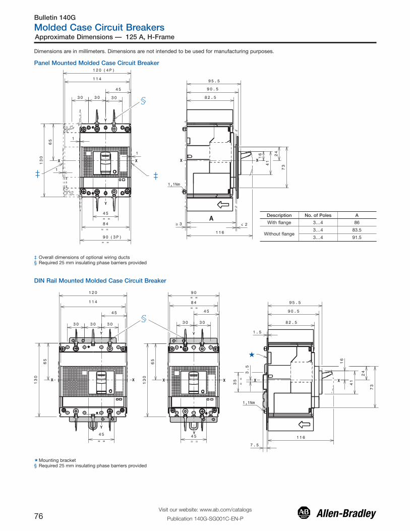
Approximate Dimensions — 125 A, H-Frame
Dimensions are in millimeters. Dimensions are not intended to be used for manufacturing purposes.
Panel Mounted Molded Case Circuit Breaker
‡ Overall dimensions of optional wiring ducts§ Required 25 mm insulating phase barriers provided
DIN Rail Mounted Molded Case Circuit Breaker
�Mounting bracket§ Required 25 mm insulating phase barriers provided
Description No. of Poles A
With flange 3…4 86
Without flange3…4 83.5
3…4 91.5
Bulletin 140G
Molded Case Circuit Breakers
77Visit our website: www.ab.com/catalogs
Publication 140G-SG001C-EN-P
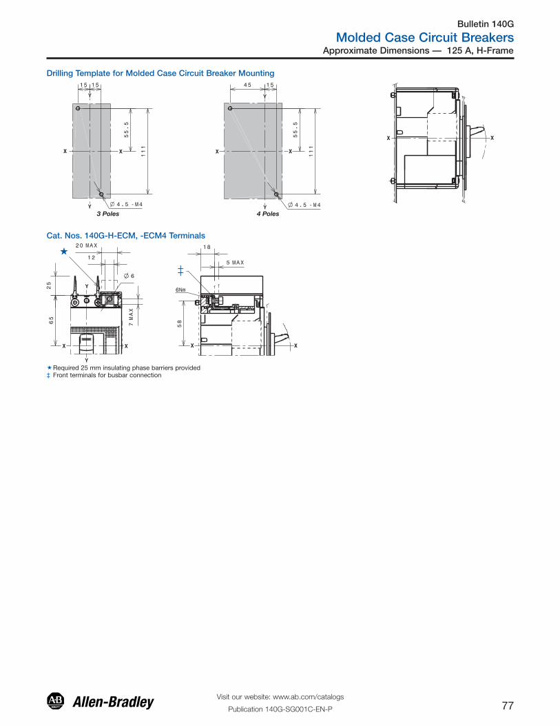
Approximate Dimensions — 125 A, H-Frame
Drilling Template for Molded Case Circuit Breaker Mounting
Cat. Nos. 140G-H-ECM, -ECM4 Terminals
�Required 25 mm insulating phase barriers provided‡ Front terminals for busbar connection
3 Poles 4 Poles
Bulletin 140G
Molded Case Circuit Breakers
78Visit our website: www.ab.com/catalogs
Publication 140G-SG001C-EN-P
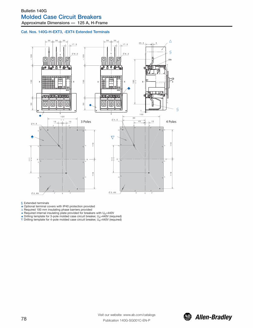
Approximate Dimensions — 125 A, H-Frame
Cat. Nos. 140G-H-EXT3, -EXT4 Extended Terminals
§ Extended terminals♣ Optional terminal covers with IP40 protection providedΔ Required 100 mm insulating phase barriers provided♦ Required internal insulating plate provided for breakers with Ue>440V♠ Drilling template for 3-pole molded case circuit breaker, Ue>440V (required)∇ Drilling template for 4-pole molded case circuit breaker, Ue>440V (required)
3 Poles 4 Poles
Bulletin 140G
Molded Case Circuit Breakers
79Visit our website: www.ab.com/catalogs
Publication 140G-SG001C-EN-P
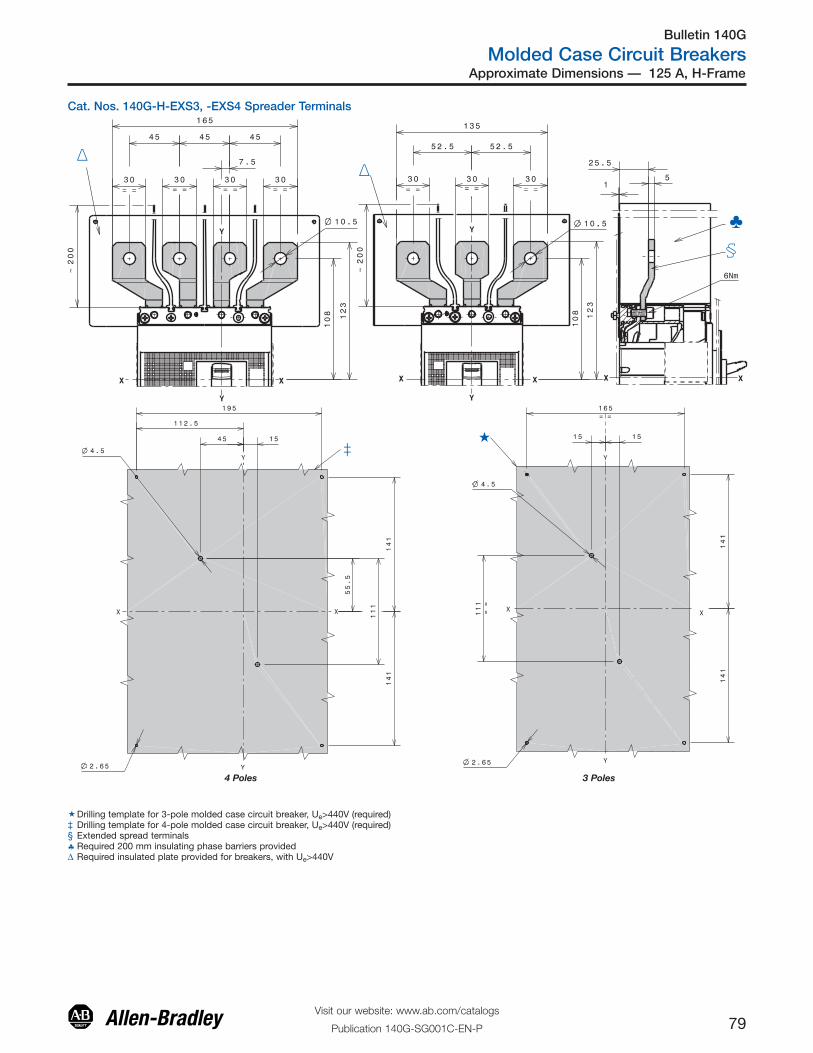
Approximate Dimensions — 125 A, H-Frame
Cat. Nos. 140G-H-EXS3, -EXS4 Spreader Terminals
�Drilling template for 3-pole molded case circuit breaker, Ue>440V (required)‡ Drilling template for 4-pole molded case circuit breaker, Ue>440V (required)§ Extended spread terminals♣ Required 200 mm insulating phase barriers providedΔ Required insulated plate provided for breakers, with Ue>440V
4 Poles 3 Poles

Bulletin 140G
Molded Case Circuit Breakers
80Visit our website: www.ab.com/catalogs
Publication 140G-SG001C-EN-P
‡ Rotary handle operating mechanism on molded case circuit breaker♦ Required 25 mm insulating phase barriers provided
Approximate Dimensions — 125 A, H-Frame
Cat. Nos. 140G-H-TLC13, -TLC14 Terminals
♦ Multi-cable terminals
Cat. Nos. 140G-H-MTL63, -MTL64 Terminals
§ Required 25 mm insulating phase barriers provided♦ Copper terminals.
Cat. No. 140G-H-RMB, -RMY Direct Rotary Operating Handle

Bulletin 140G
Molded Case Circuit Breakers
81Visit our website: www.ab.com/catalogs
Publication 140G-SG001C-EN-P
Approximate Dimensions — 125 A, H-Frame
Cat. No. 140G-H-RVM… Rotary Handle Operating Mechanism — Door Mounted
3-Pole 4-Pole
6.86[174.3]
Front of Cover
50
50(1.97)
25
25
(2) - ø 5.5
ø 35
63
31.5
25
(2) - ø 5.5
ø 35
mm(in.)
3.17[80.5]
1.28[32.5]
0.89[22.5]
3.54[90.0]
5.12[130.0]
1.44[36.5]
0.08[2.0]
4.88[124.0]
1.57[40.0]
0.89[22.5]
1.28[32.5]
5.12[130.0]
12 in. shaft: 10.89 [276.5]21 in. shaft: 19.89 [505.1]
(1.97)
(2) - ø 0.22)(2) - ø 0.22)
(ø 1.37)
(ø 1.37)
(0.98)
(0.98)(0.98)
(2.47)
(1.23)

Bulletin 140G
Molded Case Circuit Breakers
82Visit our website: www.ab.com/catalogs
Publication 140G-SG001C-EN-P
Approximate Dimensions — 125 A, H-Frame
Cat. No. 140G-H-EOP… Motor Operator
�Motor operatorΔ Drilling template for 3-pole molded case circuit breaker, mounted on mounting plate♦ Drilling template for 4-pole molded case circuit breaker, mounted on mounting plate♠ Required 25 mm insulating phase barriers provided
4 Poles3 Poles

Bulletin 140G
Molded Case Circuit Breakers
83Visit our website: www.ab.com/catalogs
Publication 140G-SG001C-EN-P
Approximate Dimensions — 125 A, H-Frame
Description No. of Poles A
With flange 4 86
Without flange 4 83.5
�Residual current module‡ Front terminals♠ Drilling template — door with direct rotary mechanism and flange∇ Drilling template — door with direct rotary mechanism, without flange& Drilling template — molded case circuit breaker mounting on mounting plate
Cat. No. 140G-H-ELP1604 Residual Current Release Module
4 Poles