Embed Size (px)
Citation preview

DEPARTMENT OF MECHATRONICS, NCERC PAMPADY.
1 | P a g e MR 332: MANUFACTURING ENGINEERING LAB MANUAL
NEHRU COLLEGE OF ENGINEERING AND RESEARCH CENTRE
(Accredited by NAAC, Approved by AICTE New Delhi, Affiliated to APJKTU)
Pampady, Thiruvilwamala(PO), Thrissur(DT), Kerala 680 588
DEPARTMENT OF MECHATRONICS
LAB MANUAL
MR 332 MANUFACTURING ENGINEERING LABORATORY
VISION OF THE INSTITUTION
To mould our youngsters into Millennium Leaders not only in Technological and Scientific
Fields but also to nurture and strengthen the innate goodness and human nature in them, to equip
them to face the future challenges in technological break troughs and information explosions and
deliver the bounties of frontier knowledge for the benefit of humankind in general and the down-
trodden and underprivileged in particular as envisaged by our great Prime Minister Panduit
Jawaharlal Nehru
MISSION OF THE INSTITUTION
To build a strong Centre of Excellence in Learning and Research in Engineering and Frontier
Technology, to facilitate students to learn and imbibe discipline, culture and spirituality, besides
encouraging them to assimilate the latest technological knowhow and to render a helping hand to
the under privileged, thereby acquiring happiness and imparting the same to others without any
reservation whatsoever and to facilitate the College to emerge into a magnificent and mighty
launching pad to turn out technological giants, dedicated research scientists and intellectual
leaders of the society who could prepare the country for a quantum jump in all fields of Science
and Technology
DEPARTMENT OF MECHATRONICS, NCERC PAMPADY.
2 | P a g e MR 332: MANUFACTURING ENGINEERING LAB MANUAL
ABOUT DEPARTMENT
Established in: 2013
Course offered: B.Tech Mechatronics Engineering
Approved by AICTE New Delhi and Accredited by NAAC
Affiliated to the University of Dr. A P J Abdul Kalam Technological University.
DEPARTMENT VISION
To develop professionally ethical and socially responsible Mechatronics engineers to serve the
humanity through quality professional education.
DEPARTMENT MISSION
1) The department is committed to impart the right blend of knowledge and quality
education to create professionally ethical and socially responsible graduates.
2) The department is committed to impart the awareness to meet the current challenges in
technology.
3) Establish state-of-the-art laboratories to promote practical knowledge of mechatronics to
meet the needs of the society
PROGRAMME EDUCATIONAL OBJECTIVES
I. Graduates shall have the ability to work in multidisciplinary environment with good
professional and commitment.
II. Graduates shall have the ability to solve the complex engineering problems by applying
electrical, mechanical, electronics and computer knowledge and engage in life long learning in
their profession.
III. Graduates shall have the ability to lead and contribute in a team entrusted with
professional social and ethical responsibilities.
IV. Graduates shall have ability to acquire scientific and engineering fundamentals necessary
for higher studies and research.
DEPARTMENT OF MECHATRONICS, NCERC PAMPADY.
3 | P a g e MR 332: MANUFACTURING ENGINEERING LAB MANUAL
PROGRAM OUTCOMES (PO’S)
Engineering Graduates will be able to:
PO 1. Engineering knowledge: Apply the knowledge of mathematics, science, engineering
fundamentals, and an engineering specialization to the solution of complex engineering
problems.
PO 2. Problem analysis: Identify, formulate, review research literature, and analyze complex
engineering problems reaching substantiated conclusions using first principles of mathematics,
natural sciences, and engineering sciences.
PO 3. Design/development of solutions: Design solutions for complex engineering problems
and design system components or processes that meet the specified needs with appropriate
consideration for the public health and safety, and the cultural, societal, and environmental
considerations.
PO 4. Conduct investigations of complex problems: Use research-based knowledge and
research methods including design of experiments, analysis and interpretation of data, and
synthesis of the information to provide valid conclusions.
PO 5. Modern tool usage: Create, select, and apply appropriate techniques, resources, and
modern engineering and IT tools including prediction and modeling to complex engineering
activities with an understanding of the limitations.
PO 6. The engineer and society: Apply reasoning informed by the contextual knowledge to
assess societal, health, safety, legal and cultural issues and the consequent responsibilities
relevant to the professional engineering practice.
PO 7. Environment and sustainability: Understand the impact of the professional engineering
solutions in societal and environmental contexts, and demonstrate the knowledge of, and need
for sustainable development.

DEPARTMENT OF MECHATRONICS, NCERC PAMPADY.
4 | P a g e MR 332: MANUFACTURING ENGINEERING LAB MANUAL
PO 8. Ethics: Apply ethical principles and commit to professional ethics and responsibilities and
norms of the engineering practice.
PO 9. Individual and team work: Function effectively as an individual, and as a member or
leader in diverse teams, and in multidisciplinary settings.
PO 10. Communication: Communicate effectively on complex engineering activities with the
engineering community and with society at large, such as, being able to comprehend and write
effective reports and design documentation, make effective presentations, and give and receive
clear instructions.
PO 11. Project management and finance: Demonstrate knowledge and understanding of the
engineering and management principles and apply these to one’s own work, as a member and
leader in a team, to manage projects and in multidisciplinary environments.
PO 12. Life-long learning: Recognize the need for, and have the preparation and ability to engage in independent and life-long learning in the broadest context of technological change.
PROGRAM SPECIFIC OUTCOMES (PSO’S)
PSO 1: Design and develop Mechatronics systems to solve the complex engineering problem by
integrating electronics, mechanical and control systems.
PSO 2: Apply the engineering knowledge to conduct investigations of complex engineering
problem related to instrumentation, control, automation, robotics and provide solutions.

DEPARTMENT OF MECHATRONICS, NCERC PAMPADY.
5 | P a g e MR 332: MANUFACTURING ENGINEERING LAB MANUAL
COURSE OUTCOME
CO 1 To acquire the basic knowledge in machining
CO 2 To familiarize shaper machine tool and milling machine
CO 3 Experimentally conduct taper turning, external and internal thread
cutting, eccentric turning using lathe
CO 4 To demonstrate machining hexagon & square from round rod using
milling and shaper machine
CO 5 Experimentally conduct spur gear and helical gear cutting in milling
machine
CO 6 To demonstrate plain surface and cylindrical grinding and counter
milling
CO 7 To familiarize CNC part programming
CO VS PO’S AND PSO’S MAPPING
CO PO1 PO2 PO3 PO4 PO5 PO6 PO7 PO8 PO9 PO10 PO11 PO12
CO 1 3 3 3 3 3 3
CO 2 2 1 3 2 1 2 2 1 3 2
CO 3 1 1 3 2 3 3 3 3 3 3 3
CO 4 1 2 2 1 3 2
CO 5 3
CO 6 3
CO 7 2 2 2 1 2 3 1 1 3 1
Note: H-Highly correlated=3, M-Medium correlated=2, L-Less correlated=1
DEPARTMENT OF MECHATRONICS, NCERC PAMPADY.
6 | P a g e MR 332: MANUFACTURING ENGINEERING LAB MANUAL
PREPARATION FOR THE LABORATORY SESSION
GENERAL INSTRUCTIONS TO STUDENTS
1. Read carefully and understand the descript ion of the experiment in the lab
manual. You may go to the lab at an earlier date to look at the experimental facilit y
and understand it better. Consult the appropriate references to be completely familiar with the
concepts and hardware.
2. Make sure that your observat ion for previous week experiment is evaluated by
the faculty member and your have transferred all the contents to your record before
entering to the lab/workshop.
3 . At t he be g inn ing o f t he c la ss , i f t he fa cu lt y o r t he in s t r u c t o r f ind s t ha t
a s t ude nt is no t adequately prepared, they will be marked as absent and not be
allowed to perform the experiment.
4. Bring necessary material needed (writ ing materials, graphs, calculators, etc.) to
perform the required preliminary analysis. It is a good idea to do sample calculations and as
much of the analysis as possible during the session. Faculty help will be available. Errors in
the procedure may thus be easily detected and rectified.
5. Please act ively part icipate in class and don‟t hesitate to ask quest ions. Please
utilize the teaching assistants fully. To encourage you to be prepared and to read
the lab manual before coming to the laboratory, unannounced questions may be asked at any
time during the lab.
6. Carelessness in personal conduct or in handling equipment may result in serious
injury to the individual or the equipment. Do not run near moving
machinery/equipment‟s. Always be on the alert for strange sounds. Guard against
entangling clothes in moving parts of machinery.
7 . S t udent s mu st fo l lo w t he p r o per d r es s co de ins id e t he la bo r a t o r y. T o
p r o t ec t c lo t h ing from dirt, wear a lab coat. Long hair should be tied back. Shoes covering
the whole foot will have to be worn.

DEPARTMENT OF MECHATRONICS, NCERC PAMPADY.
7 | P a g e MR 332: MANUFACTURING ENGINEERING LAB MANUAL
8 . I n pe r fo r ming t he e xper ime nt s , p l ea se p r o cee d ca r e fu l ly t o min imiz e
a ny wat e r s p i l ls , especially on the electric circuits and wire.
9 . Ma in t a in s i le nc e , o r der a nd d is c ip l ine in s id e t he la b. Do n‟t u se c e l l
pho ne s in s id e t he laboratory.
10. Any injury no matter how small must be reported to the instructor immediately.
11. Check with faculty members one week before the experiment to make sure that
you have the handout for that experiment and all the apparatus.
AFTER THE LABORATORY SESSION
1 . C l e a n u p y o u r w o r k a r e a .
2 . C hec k w it h t he t ec hn ic ia n be fo r e yo u lea ve .
3. Make sure you understand what kind of report is to be prepared and due
submission of record is next lab class.
4 . Do sa mp le ca lc u la t io ns a nd so me p r e l iminar y wo r k to ve r i f y t ha t
t he e xp er ime nt wa s successful
MAKE-UPS AND LATE WORK
Students must participate in all laboratory exercises as scheduled. They must obtain
permissionf r o m t h e f a c u l t y m e m b e r f o r a b s e n c e , w h i c h w o u l d b e g r a n
t e d o n l y u n d e r j u s t i f i a b l e circumstances. In such an event, a student must
make arrangements for a make-up laboratory, which will be scheduled when the time is
available after completing one cycle. Late submission will be awarded less mark for record
and internals and zero in worst cases.
LABORATORY POLICIES
1. Food, beverages & mobile phones are not allowed in the laboratory at any t ime.
2. Do not sit or place anything on instrument benches.
3. Organizing laboratory experiments requires the help of laboratory technicians
and staff. Be punctual.

DEPARTMENT OF MECHATRONICS, NCERC PAMPADY.
8 | P a g e MR 332: MANUFACTURING ENGINEERING LAB MANUAL
SYLLABUS

DEPARTMENT OF MECHATRONICS, NCERC PAMPADY.
9 | P a g e MR 332: MANUFACTURING ENGINEERING LAB MANUAL
1. STUDY ON BASIC MACHINING
AIM
To study the construction details and working principle of basic machining.
INTRODUCTION
Machining is the process of converting the given work piece into the required shape and size
with help of a machine tool. The most widely used machine tool is lathe. In simple words
machining is the process of removing certain material from the work piece.
LATHE
Lathe is the machine tool which is used to perform several operations on the work piece. Lathe is
useful in making several parts which is further assembled to make new machine. Hence lathe is
known as “mother of machines”.
BASIC WORKING PRINCIPLE OF LATHE
In lathe, the work piece is held in the chuck, a work holding device. The cutting tool is mounted
in the tool post. The chuck is rotated by means of power. When the chuck rotates, the work piece
also rotates. The tool is moved against the rotating work piece by giving small amount of depth
of cut. The material is removed in the form of chips. Continuous feed and depth of cut is given
until the required dimensions are obtained in the work piece.
TYPES OF LATHE MACHINES
There are different types of lathe machines, they are
1. Centre lathe
2. Tool room lathe
3. Bench lathe
4. Capstan lathe
5. Turret lathe
6. Automatic lathe

DEPARTMENT OF MECHATRONICS, NCERC PAMPADY.
10 | P a g e MR 332: MANUFACTURING ENGINEERING LAB MANUAL
DESCRIPTION OF LATHE
Lathe is a machine which has several parts in it. They are
1. Bed
It is the base of the machine. On its left side, the head stock is mounted and on its right it has
movable casting known as tailstock. Its legs have holes to bolt down on the ground.
2. Head stock
It consists of spindles, gears and speed changing levers. It is used to transmit the motion to the
job. It has two types one is the headstock driven by belt and the other one is the gear driven.

DEPARTMENT OF MECHATRONICS, NCERC PAMPADY.
11 | P a g e MR 332: MANUFACTURING ENGINEERING LAB MANUAL
3. Carriage
Carriage is used to carry a tool to bring in contact with the rotating work piece or to with draw
from such a contact. It operates on bed ways between the headstock and tail stock.
4. Saddle
It is an „H‟ shaped part fitted on the lathe bed. There is a hand wheel to move it on the bed way.
Cross slide, compound rest, tool post is fitted on this saddle.
a) Cross slide
It is on the upper slide of saddle in the form of dove tail. A hand wheel is provided to drive the
cross slide. It permits the cross wise movement of the tool (i.e.) movement of tool towards or
away from the operator
b) Compound rest
It is fitted over the cross slide on a turn table. It permits both parallel and angular movements to
cutting tool.
c) Tool post
It is fitted on the top most part of the compound rest. Tool is mounted on this tool post. Cutting
tool is fixed in it with the help of screws.
5. Apron
It is the hanging part in front of the carriage. It accommodates the mechanism of hand and power
feed to the cutting tool for carrying out different operations.

DEPARTMENT OF MECHATRONICS, NCERC PAMPADY.
12 | P a g e MR 332: MANUFACTURING ENGINEERING LAB MANUAL
6. Lead screw
It is a long screw with ACME threads. It is used for transmitting power for automatic feed or
feed for thread cutting operation.
7. Tail stock
It is located at the right end of the lathe bed and it cn be positioned anywhere in the bed. It is
used for supporting lengthy jobs and also carries tool to carry out operations such as tapping,
drilling, reaming.

DEPARTMENT OF MECHATRONICS, NCERC PAMPADY.
13 | P a g e MR 332: MANUFACTURING ENGINEERING LAB MANUAL
WORK HOLDING DEVICES
1. Lathe centers
They are used to support work. It has two categories of centers. Live center is one which is fitted
in the headstock spindle. Dead is another one which is fitted in the tail stock.
2. Chuck
It is a device used to hold a job. It is easily fitted on the thread cut on the end of head stock
spindle. Various types of chuck are a) Two jaw chuck b) three jaw chuck c) four jaw chuck d)
collet chuck
e) Magnetic chuck

DEPARTMENT OF MECHATRONICS, NCERC PAMPADY.
14 | P a g e MR 332: MANUFACTURING ENGINEERING LAB MANUAL
3. Face plate
4. Catch plate
5. Lathe carriers or dog’s
6. Steady rest
7. Mandrel
8. Follower rest

DEPARTMENT OF MECHATRONICS, NCERC PAMPADY.
15 | P a g e MR 332: MANUFACTURING ENGINEERING LAB MANUAL
CUTTING TOOLS USED
For making a finished job on lathe machine, various types of cutting tools are used. One of them
is single point cutting tool which is used to perform several operations on the work piece.
Various types of cutting tools are
1. Facing Tool
It is used for facing the longitudinal ends of the job. Its shape is like a knife.
2. Rough Turning Tool
It is used to remove excess material from the work piece in quick time. It can be used to give
large depth of cut and work at coarse feed.
3. Finishing Tool
It is used for getting smooth finish on the work piece. Its point is a little more round.
4. Radius Tool
Jobs which need round cutting are done with this tool. Its type is a) Convex radius tool b)
concave radius tool
5. Parting Tools

DEPARTMENT OF MECHATRONICS, NCERC PAMPADY.
16 | P a g e MR 332: MANUFACTURING ENGINEERING LAB MANUAL
It is used to cut the jobs into two parts. It is also used for grooving.
6. Form Turning Tool
It is used for jobs which require both convex and concave turning.
7. Thread Cutting Tool
It is used for making internal or external threads on the work piece. The tool nose is designed
with a definite profile for taking threads.
8. Drill Tool
It is used for making holes of various diameters on the job. Drill bit of various sizes of diameter
are available.
9. Boring Tool
It used for enlarging the drill hole.
10. Knurling Tool
Drawing slanting or square projecting lines on the surface of a job is known as knurling. It is
used for making better grip on the surface of a job.

DEPARTMENT OF MECHATRONICS, NCERC PAMPADY.
17 | P a g e MR 332: MANUFACTURING ENGINEERING LAB MANUAL
TOOL MATERIALS
1. The single point cutting tools are made of high speed steel. (H. S. S)
2. The main alloying elements in 18 – 4 – 1 HSS tools are 18 % tungsten, 4% chromium and 1 %
Vanadium. 5 to 10 % cobalt is also added to improve the heat resisting properties of the tool.
3. General purpose hand cutting tools are usually made from carbon steel or tool steel.
4. Carbide tipped tools fixed in tool holders, are mostly used in production shops.
CUTTING TOOL ANGLES
1) Top rake angle (back rake angle) a. If the slope is given to the face or surface of the tool and if
this slope is along the tools length then it is called top rake angle. It is usually 15° to 20°.
2) Side rake angle

DEPARTMENT OF MECHATRONICS, NCERC PAMPADY.
18 | P a g e MR 332: MANUFACTURING ENGINEERING LAB MANUAL
a. If the slope is given to the face or top of the tool along the tools width then it is called side
rake angle. It lies between 6° and 15°.
3) Clearance angle (relief angle)
a. Types:
1. Side clearance angle
2. End clearance angle.
b. They are provided to keep surface of the tool clear of the work piece.
4) Cutting edge angle (Types)
1. Side cutting edge angle – (generally 15°) it is an angle, the side cutting edge makes with the
axis of the tool.
2. End cutting edge angle – (from 7° to 15°) it is an angle, the end cutting edge makes with the
width of the tool.
5) Lip angle (cutting angle)
a. It is the angle between the face and the end surface of the tool.
6) Nose angle
b. It is the angle between the side cutting edge and end cutting edge.
LATHE OPERATIONS
1. Facing
• It is done for getting fine finish (good surface finish) on the face of the job.
• Facing tool is set at an angle to the work piece.
• The tool is fed from the Centre of work piece towards the outer surface against the rotating
work piece.

DEPARTMENT OF MECHATRONICS, NCERC PAMPADY.
19 | P a g e MR 332: MANUFACTURING ENGINEERING LAB MANUAL
• Depth of cut is low for the facing operation.
2. Plain Turning
• It is done for reducing the diameter of the work piece.
• A cutting tool with 70° setting angle is used for roughing operation.
• More feed is given for rough turning while less feed is given for finishing.
• Work piece is held in chuck and tool is set to center height of the work piece.
5. Knurling
DEPARTMENT OF MECHATRONICS, NCERC PAMPADY.
20 | P a g e MR 332: MANUFACTURING ENGINEERING LAB MANUAL
• It is process of making serrations on the work piece.
• Knurling tools of different shape and size are used to make grip on the work piece. It has two
hardened steel rollers.
• The tool is held in tool post and pressed against the rotating work piece.
• Work piece is rotated at lower speed and small amount of feed is given.
6. Drilling
• It is a process of making a hole on the work piece
• Job is held in chuck while the drill is held in the tail stock sleeve.
• Feed is given by rotating the hand wheel in the tail stock which pushes the tailstock sleeve.
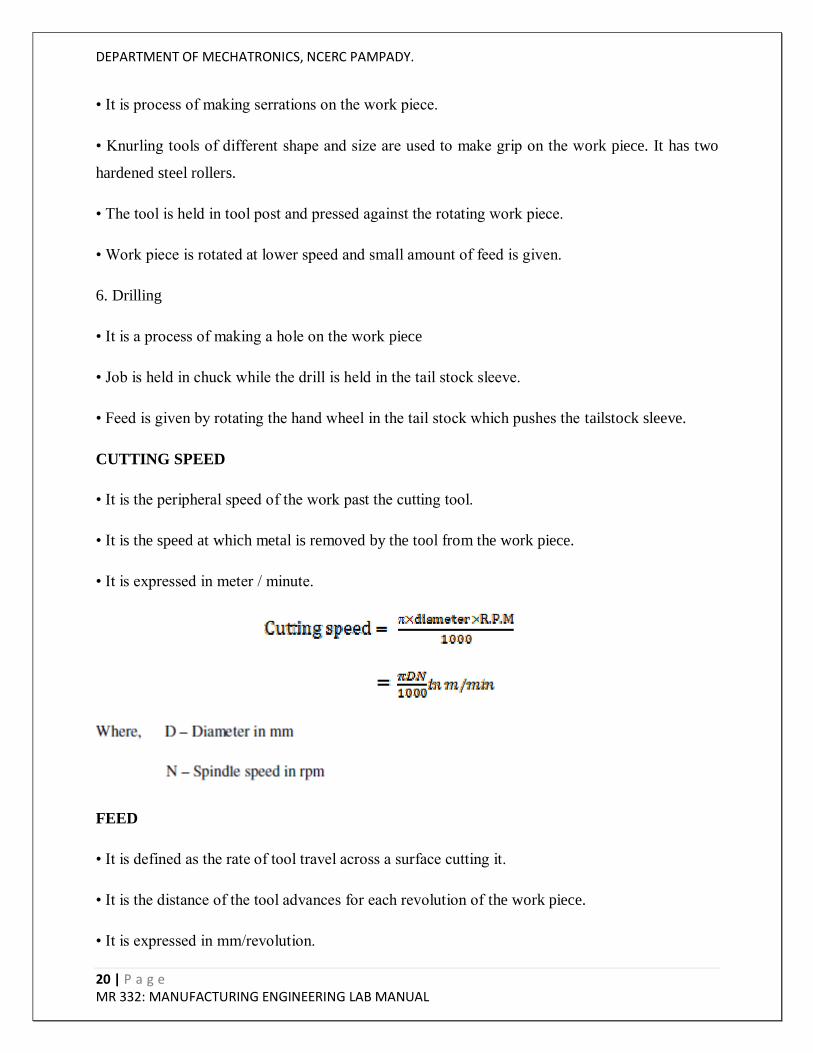
CUTTING SPEED
• It is the peripheral speed of the work past the cutting tool.
• It is the speed at which metal is removed by the tool from the work piece.
• It is expressed in meter / minute.
FEED
• It is defined as the rate of tool travel across a surface cutting it.
• It is the distance of the tool advances for each revolution of the work piece.
• It is expressed in mm/revolution.

DEPARTMENT OF MECHATRONICS, NCERC PAMPADY.
21 | P a g e MR 332: MANUFACTURING ENGINEERING LAB MANUAL
DEPTH OF CUT
• It is the perpendicular distance measured from the machined surface to the uncut surface of
work. It is expressed in mm.
RESULT
Thus the basic machining was studied.

DEPARTMENT OF MECHATRONICS, NCERC PAMPADY.
22 | P a g e MR 332: MANUFACTURING ENGINEERING LAB MANUAL
2. STUDY OF SHAPER
AIM
To study the construction details and working principle of a shaper machine tool.
CONSTRUCTION AND WORKING PRINCIPLE
• Shaper is a reciprocating type of machine tool. It is used for machining the surfaces. The
surface may be horizontal and vertical indeed. The shaper has the main parts such as base, table,
column, cross-rail, ram and tool head. The base bolted to the floor, it is made of C.I and absorbs
entire load.
• The column is box type in which return mechanism of ram is provided. At the top of the
column, there are two mechanical I guide ways. The ram reciprocating on their guide ways in the
front vertical guide ways in which the table the rectangular hallow block. It slides rail is mounted
guide ways of iron-rail. It has machine surface on the top and slides. These surfaces have T slots
for clamping work. The rail carries the tool head in which the tool head is in vertical position.
The ram reciprocation on the guide ways on top of column.
• The work is held on the table by using correct work holding device. A single tool is in vertical
position of the cutting stroke (forward bias) the feed is given at the end of each cutting stroke
during the return stroke, no metal is cut. The cutting stroke takes place at slow speed and the
return stroke takes place at a faster speed. The faster feed rate is obtained using quick return.
• By adjusting the work piece position as tool position step cutting, v-cutting, etc…., is machined
in shaping machine.

DEPARTMENT OF MECHATRONICS, NCERC PAMPADY.
23 | P a g e MR 332: MANUFACTURING ENGINEERING LAB MANUAL
RESULT
Thus the construction details and the working principle of the standard shaper are studied.

DEPARTMENT OF MECHATRONICS, NCERC PAMPADY.
24 | P a g e MR 332: MANUFACTURING ENGINEERING LAB MANUAL
3. STUDY OF MILLING MACHINE
AIM
To study the construction details and working principle of milling machine.
CONSTRUCTION AND WORKING PRINCIPLE
• A milling machine is a machine tool that renioues metal from the work which is fed against a
retailing multipoint cutter. The cutter rotates at a high speed and because of the multiple cutting
edges it removes metal at a very fast rate.
• The base of the machine is grey iron casting, actually machined on its top and bottom surface.
It carries the column at its one end. The column is the main support structure mounted vertically
on the base. The column is box shaped, heavily ribbed inside and bases all the driving
mechanism for the spindle and table feed. The front vertical face of column has details guide
ways for supporting the knee. The top of the column is finished to hold on over arm that extends
outward at front machine.

DEPARTMENT OF MECHATRONICS, NCERC PAMPADY.
25 | P a g e MR 332: MANUFACTURING ENGINEERING LAB MANUAL
The knee is grid grey iron casting that slides up and down on the vertical away of column face.
The knee gives the feed mechanism of table and different controls operate is saddle placed on top
surfaces of knee which slides on guide ways perpendicular to column face. The feed movement
of saddle is obtained by hand or by power.
• The overhanging arm is mounted on the top column the arm is adjusted so that bearing support
may be provided of cutter. The spindle has the mouse taps at its front face in which various
cutting tools may be inserted. The taper chance for proper alignment with the machine spindle
handling taper holes at their none.
RESULT
Thus the construction and working principle of milling machine is studied.

DEPARTMENT OF MECHATRONICS, NCERC PAMPADY.
26 | P a g e MR 332: MANUFACTURING ENGINEERING LAB MANUAL
4. TAPER TURNING OPERATION BY USING A LATHE
AIM
To machine a work piece by facing, plain turning and taper turning operation using a lathe.
MATERIALS REQUIRED
Mild steel polished round rod - f 25 X 100 mm
TOOLS REQUIRED
_ Lathe machine
_ Steel Rule
_ Cutting tool
_ Vernier Caliper
_ Outside Caliper
_ Spanner
FORMULA
1) The taper angle is calculated using the following formula:

DEPARTMENT OF MECHATRONICS, NCERC PAMPADY.
27 | P a g e MR 332: MANUFACTURING ENGINEERING LAB MANUAL
PROCEDURE
1. The given work piece is held firmly in a lathe chuck.
2. The cutting tool is set in a tool post such that the point of the Cutting tool coincides with the
lathe axis.
3. The machine is switched on to revolve the work piece at the selected speed.
4. By giving Cross feed and longitudinal feed to the cutting tool, the facing and turning
operations are done respectively.
5. The compound rest is swiveled for the calculated taper angle.
6. By giving angular feed to the cutting tool through the compound slide the taper turning
operation is done.
7. The machine is switched off.
8. The work piece is removed from the chuck and all the dimensions are measured and checked.

DEPARTMENT OF MECHATRONICS, NCERC PAMPADY.
28 | P a g e MR 332: MANUFACTURING ENGINEERING LAB MANUAL
CALCULATION
1) Taper angle calculation:

DEPARTMENT OF MECHATRONICS, NCERC PAMPADY.
29 | P a g e MR 332: MANUFACTURING ENGINEERING LAB MANUAL

DEPARTMENT OF MECHATRONICS, NCERC PAMPADY.
30 | P a g e MR 332: MANUFACTURING ENGINEERING LAB MANUAL
RESULT
The given work piece as shown in fig. is subjected to facing, plain turning and taper turning
operation to become a finished work piece as shown in fig.
DEPARTMENT OF MECHATRONICS, NCERC PAMPADY.
31 | P a g e MR 332: MANUFACTURING ENGINEERING LAB MANUAL
5. EXTERNAL THREAD CUTTING BY USING A LATHE
AIM
To machine a work piece by facing, plain turning and external thread cutting
operations using a lathe.
MATERIALS REQUIRED
• Mild steel polished round rod - f 25 X 100 mm
TOOLS REQUIRED
_ Outside Caliper
_ Turning tool .
_ Vernier Caliper
_ External V – thread cutting tool
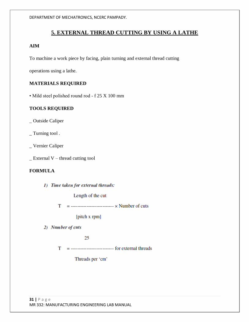
FORMULA

DEPARTMENT OF MECHATRONICS, NCERC PAMPADY.
32 | P a g e MR 332: MANUFACTURING ENGINEERING LAB MANUAL
PROCEDURE
1. The given work piece is held firmly in a lathe chuck.
2. The cutting tool is set in a tool post such that the point of the Cutting tool coincides with the
lathe axis.
3. The machine is switched on to revolve the work piece at the selected speed.
4. By giving Cross feed and longitudinal feed to the cutting tool, the facing and turning
operations are done respectively.
5. The speed of the work piece is reduced.
6. The machine is switched off and the change gears of calculated teeth (as per calculation) are
connected.
7. Again the machine is switched on.
8. The external thread cutting operation is done using external thread cutting tool by engaging
thread cutting mechanism.
9. The machine is switched off.
10. The work piece is removed from the chuck and all the dimensions are measured and checked.

DEPARTMENT OF MECHATRONICS, NCERC PAMPADY.
33 | P a g e MR 332: MANUFACTURING ENGINEERING LAB MANUAL
CALCULATION
The number of teeth on change gears is calculated using the following formula:
Driver teeth/ Driven teeth = Pitch of the work / pitch of the lead screw
RESULT
The given work piece as shown in fig. is subjected to facing, plain turning, knurling and external
thread cutting operations to become a finished work piece as shown in fig.

DEPARTMENT OF MECHATRONICS, NCERC PAMPADY.
34 | P a g e MR 332: MANUFACTURING ENGINEERING LAB MANUAL
6. KNURLING OPERATION BY USING A LATHE
AIM
To machine a work piece by facing, plain turning, knurling operations using a lathe.
MATERIALS REQUIRED
• Mild steel polished round rod - f 25 X 100 mm
TOOLS REQUIRED
_ Lathe machine
_ Turning tool
_ Knurling tool
_ Outside Caliper
_ Steel Rule
_ Vernier Caliper
FORMULA

DEPARTMENT OF MECHATRONICS, NCERC PAMPADY.
35 | P a g e MR 332: MANUFACTURING ENGINEERING LAB MANUAL
PROCEDURE
1. The given work piece is held firmly in a lathe chuck.
2. The cutting tool is set in a tool post such that the point of the Cutting tool coincides with the
lathe axis.
3. The machine is switched on to revolve the work piece at the selected speed.
4. By giving Cross feed and longitudinal feed to the cutting tool, the facing and turning
operations are done respectively.
5. The speed of the work piece is reduced.
6. The knurling operation is done using knurling tool.
7. Again the machine is switched on.
8. The machine is switched off.
9. The work piece is removed from the chuck and all the dimensions are measured and checked.
RESULT
The given work piece as shown in fig. is subjected to facing, plain turning, knurling operations to
become a finished work piece as shown in fig.

DEPARTMENT OF MECHATRONICS, NCERC PAMPADY.
36 | P a g e MR 332: MANUFACTURING ENGINEERING LAB MANUAL
7. INTERNAL THREAD CUTTING BY USING A LATHE
AIM
To machine a work piece by facing, plain turning and internal thread cutting operations using a
lathe.
MATERIALS REQUIRED
• Mild steel polished round rod - f 25 X 100 mm
TOOLS REQUIRED
_ Lathe machine
_ Outside Caliper
_ Turning tool
_ Steel Rule .
_ Vernier Caliper
_ Internal V – thread cutting tool
FORMULA

DEPARTMENT OF MECHATRONICS, NCERC PAMPADY.
37 | P a g e MR 332: MANUFACTURING ENGINEERING LAB MANUAL
PROCEDURE
1. The given work piece is held firmly in a lathe chuck.
2. The cutting tool is set in a tool post such that the point of the Cutting tool coincides with the
lathe axis.
3. The machine is switched on to revolve the work piece at the selected speed.
4. By giving Cross feed and longitudinal feed to the cutting tool, the facing and turning
operations are done respectively.
5. The speed of the work piece is reduced.
6. The machine is switched off and the change gears of calculated teeth(as per calculation) are
connected.
7. Again the machine is switched on.
8. The internal thread cutting operation is done using internal thread cutting tool by engaging
thread cutting mechanism.
9. The machine is switched off.
10. The work piece is removed from the chuck and all the dimensions are measured and checked.

DEPARTMENT OF MECHATRONICS, NCERC PAMPADY.
38 | P a g e MR 332: MANUFACTURING ENGINEERING LAB MANUAL
CALCULATION
The number of teeth on change gears is calculated using the following formula:
Driver teeth/ Driven teeth = Pitch of the work / pitch of the lead screw
RESULT
The given work piece as shown in fig. is subjected to facing, plain turning, and
internal thread cutting operations to become a finished work piece as shown in fig.

DEPARTMENT OF MECHATRONICS, NCERC PAMPADY.
39 | P a g e MR 332: MANUFACTURING ENGINEERING LAB MANUAL
8. ECCENTRIC TURNING OPERATION BY USING A LATHE
AIM
To machine a work piece by facing, plain turning, eccentric operations by use
a four jaw chuck lathe.
MATERIALS REQUIRED
• Mild steel polished round rod - f 25 X 100 mm
TOOLS REQUIRED
_ Four jaw chuck lathe
_ Outside Caliper
_ Turning tool
_ Vernier caliper
_ Steel Rule
FORMULA
1) Speed , N = 1000 x s / _ x D
2) No. of passes = D-d / 2 x depth of cut
3) Time for eccentric turning = L / F x N

DEPARTMENT OF MECHATRONICS, NCERC PAMPADY.
40 | P a g e MR 332: MANUFACTURING ENGINEERING LAB MANUAL
PROCEDURE
1. The given work piece is held firmly in a lathe chuck.
2. The cutting tool is set in a tool post such that the point of the Cutting tool coincides with the
lathe axis.
3. The machine is switched on to revolve the work piece at the selected speed.
4. By giving Cross feed and longitudinal feed to the cutting tool, the facing and turning
operations are done respectively.
5. The speed of the work piece is reduced.
6. The four jaw chuck is manually adjusted for the offset purpose to make the eccentricity.
7. Again the machine is switched on.
8. The machine is switched off.
9. The work piece is removed from the chuck and all the dimensions are measured and checked.
RESULT
The given work piece as shown in fig. is subjected to facing, plain turning, knurling operations to
become a finished work piece as shown in fig.

DEPARTMENT OF MECHATRONICS, NCERC PAMPADY.
41 | P a g e MR 332: MANUFACTURING ENGINEERING LAB MANUAL
9. MACHINING HEXAGON FROM ROUND ROD BY USING A MILLING
MACHINE
AIM
To machine a hexagon in the given work piece to the dimensions as shown in
the figure using Shaping Machine.
TOOLS REQUIRED
_ Milling Machine,
_ Scriber, Divider,
_ Steel Rule,
_ Chalk piece,
_ Bevel Protractor.
FORMULA

DEPARTMENT OF MECHATRONICS, NCERC PAMPADY.
42 | P a g e MR 332: MANUFACTURING ENGINEERING LAB MANUAL
PROCEDURE
1. The given work piece is measured for its initial dimensions.
2. With the help of scriber, mark the hexagon dimensions in the work piece.
3. Fix the work piece in the vice of the shaping machine.
4. After fixing the work piece and the shaping tool, allow the ram to reciprocate.
5. Start the shaping process by giving the required depth by lowering the tool.
6. Slowly increase the depth of cut and repeat the procedure to make the hexagon shape.
7. The work piece is now checked for final dimensions.
RESULT
Thus, a hexagon is machined in the given work piece to the dimensions as shown in the figure
using Shaping Machine.

DEPARTMENT OF MECHATRONICS, NCERC PAMPADY.
43 | P a g e MR 332: MANUFACTURING ENGINEERING LAB MANUAL
10. MACHINING SQUARE FROM ROUND ROD BY USING A SHAPER
AIM
To generate a square from rounded on the given work piece in a shaper machine.
TOOLS REQUIRED
_ Shaping machine
_ Steel rule
_ Hammer
_ Shaper tool
_ Try Square
FORMULA

DEPARTMENT OF MECHATRONICS, NCERC PAMPADY.
44 | P a g e MR 332: MANUFACTURING ENGINEERING LAB MANUAL
PROCEDURE
1. The job was checked to the given dimensions.
2. The square was scribed in the outer circle of diameter exactly and punching was done.
3. The job was attached in the vice of a shaper.
4. The job was checked for perpendicular dimension.
5. Then the square from round was obtained in the shaper.
6. The work piece was removed and burns are removed with accuracy was checked.
RESULT
Thus the square from round was performed on the given dimension in a shaper machine with the
required dimensions.

DEPARTMENT OF MECHATRONICS, NCERC PAMPADY.
45 | P a g e MR 332: MANUFACTURING ENGINEERING LAB MANUAL
11. SPUR GEAR CUTTING IN MILLING MACHINE
AIM:
To perform spur gear cutting using vertical milling machine on a work piece.
INTRODUCTION:
Spur gears or straight-cut gears are the simplest type of gear. They consist of a cylinder or disk
with the teeth projecting radially, and although they are not straight-sided in form (they are
usually of special form to achieve constant drive ratio, mainly involute), the edge of each tooth is
straight and aligned parallel to the axis of rotation. These gears can be meshed together correctly
only if they are fitted to parallel shafts.
MATERIAL USED
Cast iron blank
TOOLS REQUIRED
1. Vertical Milling machine
2. vernier caliper
3. Holding Materials
4. Milling Tools
5. Mandrel
DEPARTMENT OF MECHATRONICS, NCERC PAMPADY.
46 | P a g e MR 332: MANUFACTURING ENGINEERING LAB MANUAL
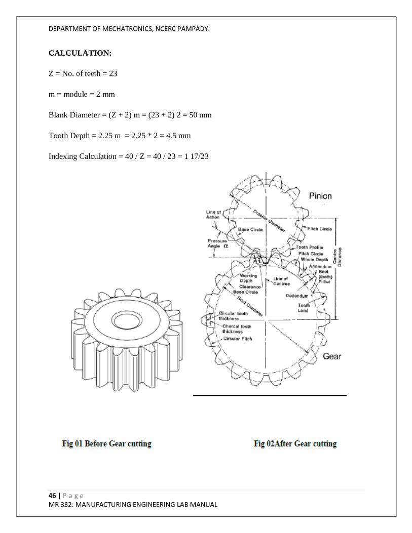
CALCULATION:
Z = No. of teeth = 23
m = module = 2 mm
Blank Diameter = (Z + 2) m = (23 + 2) 2 = 50 mm
Tooth Depth = 2.25 m = 2.25 * 2 = 4.5 mm
Indexing Calculation = 40 / Z = 40 / 23 = 1 17/23

DEPARTMENT OF MECHATRONICS, NCERC PAMPADY.
47 | P a g e MR 332: MANUFACTURING ENGINEERING LAB MANUAL
PROCEDURE:
Calculate the gear tooth proportions.
Blank diameter = ( Z + 2 ) m
Tooth depth = 2.25 m
Tooth width = 1.5708 m where,
Z = Number of teeth required
m = module Indexing calculation
Index crank movement = 40 / Z
The dividing head and the tail stock are bolted on the machine table. Their axis must be
set parallel to the machine table.
The gear blank is held between the dividing head and tailstock using a mandrel. The
mandrel is connected with the spindle of dividing head by a carrier and catch plate.
The cutter is mounted on the arbor. The cutter is centred accurately with the gear blank.
Set the speed and feed for machining.
For giving depth of cut, the table is raised till the periphery of the gear blank just touches
the cutter.
The micrometer dial of vertical feed screw is set to zero in this position.
Then the table is raised further to give the required depth of cut.
The machine is started and feed is given to the table to cut the first groove of the blank.
After the cut, the table is brought back to the starting position.
Then the gear blank is indexed for the next tooth space.
This is continued till all the gear teeth are cut.
RESULT:
The given work piece as is subjected to gear generating operation to become a finished work
piece

DEPARTMENT OF MECHATRONICS, NCERC PAMPADY.
48 | P a g e MR 332: MANUFACTURING ENGINEERING LAB MANUAL
12. HELICAL GEAR CUTTING IN MILLING MACHINE
AIM:
To perform Helical Gear Cutting using milling machine on a work piece.
INTRODUCTION:
Helical or "dry fixed" gears offer a refinement over spur gears. The leading edges of the teeth are
not parallel to the axis of rotation, but are set at an angle. Since the gear is curved, this angling
causes the tooth shape to be a segment of a helix. Helical gears can be meshed in parallel or
crossed orientations.
MATERIAL USED
Cast iron
TOOLS REQUIRED
1. Vertical Milling machine
2. vernier caliper
3. Holding Materials
4. Milling Tools

DEPARTMENT OF MECHATRONICS, NCERC PAMPADY.
49 | P a g e MR 332: MANUFACTURING ENGINEERING LAB MANUAL
DIAGRAM
HELICAL GEAR FORMULAS

DEPARTMENT OF MECHATRONICS, NCERC PAMPADY.
50 | P a g e MR 332: MANUFACTURING ENGINEERING LAB MANUAL
PROCEDURE:
The dividing head and the tail stock are bolted on the machine table. Their axis must be
set parallel to the machine table.
The gear blank is held between the dividing head and tailstock using a mandrel. The
mandrel is connected with the spindle of dividing head by a carrier and catch plate.
The cutter is mounted on the arbor. The cutter is centred accurately with the gear blank.
Set the speed and feed for machining.
For giving depth of cut, the table is raised till the periphery of the gear blank just touches
the cutter.
The micrometer dial of vertical feed screw is set to zero in this position.
Then the table is raised further to give the required depth of cut.
The machine is started and feed is given to the table to cut the first groove of the blank.
After the cut, the table is brought back to the starting position.
Then the gear blank is indexed for the next tooth space.
This is continued till all the gear teeth are cut.
RESULT:
The given work piece as is subjected to gear generating operation to become a finished work
piece

DEPARTMENT OF MECHATRONICS, NCERC PAMPADY.
51 | P a g e MR 332: MANUFACTURING ENGINEERING LAB MANUAL
13. GEAR GENERATION IN SHAPING MACHINE
AIM:
To machine a Spur Gear using a gear Hobbing machine.
MATERIALS REQUIRED:
Cast iron blank
TOOLS REQUIRED:
1. Gear Shaping machine
2. Gear tooth vernier
3. Spanners
PROCEDURE:
The given work piece is held firmly on the spindle of the gear shapping machine
The workipice is set at an angle to shaping tool angle for cutting spur gear.
The change gears are set for the desired speed of work piece and
The machine is switched on.
The work piece and Shaper are allowed to remove the metal at the desired speed.
The work piece is given full deph of cut equals to the tooth depth.
The cutter is given feed for the full width of the work.
After machining all gear teeth on the blank the machine is switched off.
The gear teeth are checked using a gear tooth vernier.

DEPARTMENT OF MECHATRONICS, NCERC PAMPADY.
52 | P a g e MR 332: MANUFACTURING ENGINEERING LAB MANUAL
CALCULATION:
Z = No. of teeth = 23
m = module = 2 mm
Blank Diameter = (Z + 2) m = (23 + 2) * 2 = 50 mm
Tooth Depth = 2.25 m = 2.25 * 2 = 4.5 mm
Indexing Calculation = 40 / Z = 40 / 23 = 1 17/23
RESULT:
The given work piece as shown in fig (1) is subjected to gear generating operation to become a
finished work piece as shown in fig (2). In gear Shaping Machine.

DEPARTMENT OF MECHATRONICS, NCERC PAMPADY.
53 | P a g e MR 332: MANUFACTURING ENGINEERING LAB MANUAL
14. PLAIN SURFACE GRINDING
AIM:
To perform a Plain surface grinding operation on the given work piece for the given dimensions
PRINCIPLE:
The principle involved in this process is to make flat surface on the given work piece. The cutter
is moved perpendicular to the work piece and the grinding is done.
REQUIREMENTS
1. Grinding Machine
2. Work Piece 100x50x6 mm MS Plate
3. Grinding Wheel
PROCEDURE:
At first work piece is placed in the magnetic chuck.
The work piece should be light weight so that it cannot be removed from the magnetic
chuck easily.
Various arrangements regarding the positions of work piece is done.
Grinding wheel and grinding spindle are kept in position with the work piece.
Before switching on the motor, necessary steps should taken. For proper grinding process
wheel speed, work speed, transverse speed of the wheel in feed, area of contact is to be
noted.
While running the area of contact is adjusted accordingly to the spindle in order to
remove the surface.
It is done slowly to remove the materials on the both sides.
In surface grinding the stock removal rate is given by Q = bdy Where d =depth of cut (m)
b =width of cut (m) y =work velocity (m/s) q =rate of stroke (m3/s)

DEPARTMENT OF MECHATRONICS, NCERC PAMPADY.
54 | P a g e MR 332: MANUFACTURING ENGINEERING LAB MANUAL
RESULT:
Thus the surface grinding is done for the given dimensions.

DEPARTMENT OF MECHATRONICS, NCERC PAMPADY.
55 | P a g e MR 332: MANUFACTURING ENGINEERING LAB MANUAL
15. CYLINDRICAL GRINDING
AIM:
To grind the cylindrical surface of the given materials as per the given dimensions
REQUIREMENTS:
1. Grinding Machine
2. Grinding Wheel
3. Work Piece
4. Steel rule.
5. Outside calipers.
6. Cutting tool.
PROCEDURE:
The given work piece is first fitted in the chuck of the lathe.
By fitting the tool in tool post the work piece will be reduced to given dimensions.
First reduce the diameter to 23mm size then reduced the diameter to 15mm and 18mm at
the middle.
By facing the work piece to the tool work piece is reduced to 70mm.
After the preliminary lathe operation, the work piece is held in the ends of the cylindrical
grinder.
The grinding wheel is turned on and it is moved towards the work piece such that the
surfaces of the cylindrical position are grinded to +-0.2mm.

DEPARTMENT OF MECHATRONICS, NCERC PAMPADY.
56 | P a g e MR 332: MANUFACTURING ENGINEERING LAB MANUAL
RESULT:
Thus the required dimension of cylindrical surface is obtained.

DEPARTMENT OF MECHATRONICS, NCERC PAMPADY.
57 | P a g e MR 332: MANUFACTURING ENGINEERING LAB MANUAL
16. CNC PART PROGRAMMING
AIM:
To Study about the cnc part programming
INTRODUCTION
A Part program is a set of instructions given to a Computerized numerical control (CNC)
machine.
If the complex-shaped component requires calculations to produce the component are done by
the programming software contained in the computer. The programmer communicates with this
system through the system language, which is based on words. There are various programming
languages developed in the recent past, such as APT (Automatically Programmed Tools),
ADAPT, AUTOSPOT, COMPAT-II, 2CL, ROMANCE, SPLIT is used for writing a computer
programme, which has English like statements. A translator known as compiler program is used
to translate it in a form acceptable to MCU.
The programmer has to do only following things :
(a) Define the work part geometry.
(b) Defining the repetition work.
(c) Specifying the operation sequence.

DEPARTMENT OF MECHATRONICS, NCERC PAMPADY.
58 | P a g e MR 332: MANUFACTURING ENGINEERING LAB MANUAL
STANDARD G AND M CODES
The most common codes used when programming NC machines tools are G-codes (preparatory
functions), and M codes (miscellaneous functions). Other codes such as F, S, D, and T are used
for machine functions such as feed, speed, cutter diameter offset, tool number, etc. G-codes are
sometimes called cycle codes because they refer to some action occurring on the X, Y, and/or Z-
axis of a machine tool. The G-codes are grouped into categories such as Group 01, containing
codes G00, G01, G02, G03, which cause some movement of the machine table or head. Group
03 includes either absolute or incremental programming. A G00 code rapidly positions the
cutting tool while it is above the workpiece from one point to another point on a job. During the
rapid traverse movement, either the X or Y-axis can be moved individually or both axes can be
moved at the same time. The rate of rapid travel varies from machine to machine.

DEPARTMENT OF MECHATRONICS, NCERC PAMPADY.
59 | P a g e MR 332: MANUFACTURING ENGINEERING LAB MANUAL
G-CODES (PREPARATORY FUNCTIONS)
Code Function
G00 Rapid positioning
G01 Linear interpolation
G02 Circular interpolation clockwise (CW)
G03 Circular interpolation counterclockwise (CCW)
G20 Inch input (in.)
G21 Metric input (mm)
G24 Radius programming
G28 Return to reference point
G29 Return from reference point
G32 Thread cutting
G40 Cutter compensation cancel
G41 Cutter compensation left
G42 Cutter compensation right
G43 Tool length compensation positive (+) direction
G44 Tool length compensation minus (-) direction
G49 Tool length compensation cancels
G 53 Zero offset or M/c reference
G54 Settable zero offset
G84 canned turn cycle

DEPARTMENT OF MECHATRONICS, NCERC PAMPADY.
60 | P a g e MR 332: MANUFACTURING ENGINEERING LAB MANUAL
G90 Absolute programming
G91 Incremental programming
M-CODES (MISCELLANEOUS FUNCTIONS)
M or miscellaneous codes are used to either turn ON or OFF different functions, which control
certain machine tool operations. M-codes are not grouped into categories, although several codes
may control the same type of operations such as M03, M04, and M05, which control the machine
tool spindle. Some of important codes are given as under with their function s:
Code Function
M00 Program stop
M02 End of program
M03 Spindle start (forward CW)
M04 Spindle start (reverse CCW)
M05 Spindle stop
M06 Tool change
M08 Coolant on
M09 Coolant off
M10 Chuck - clamping
M11 Chuck - unclamping
M12 Tailstock spindle out
M13 Tailstock spindle in

DEPARTMENT OF MECHATRONICS, NCERC PAMPADY.
61 | P a g e MR 332: MANUFACTURING ENGINEERING LAB MANUAL
M18 Tool post rotation reverse
M30 End of tape and rewind or main program end
M98 Transfer to subprogram
M99 End of subprogram
Note : On some machines and controls, some may be differ.
RESULTS
Thus the Study about the cnc part programming has been completed

DEPARTMENT OF MECHATRONICS, NCERC PAMPADY.
62 | P a g e MR 332: MANUFACTURING ENGINEERING LAB MANUAL
17. CONTOUR MILLING USING VERTICAL MILLING
MACHINE
AIM:
To study the contour milling using vertical milling machine on a work piece
INTRODUCTION:
Machining of Irregular Parts and it is an outline especially of a curving or irregular figure
MATERIAL USED
Cast Iron
SURFACE CONTOURING
The end mill, which is used in surface contouring has a hemispherical end and is called ball-end
mill. The ball-end mill is fed back and forth across the work piece along a curvilinear path at
close intervals to produce complex three-dimensional surfaces. Similar to profile milling, surface
contouring require relatively simple cutting tool but advanced, usually computer-controlled feed
control system.

DEPARTMENT OF MECHATRONICS, NCERC PAMPADY.
63 | P a g e MR 332: MANUFACTURING ENGINEERING LAB MANUAL
USING CODES
G00 - Positioning at rapid speed; Milling and Turning
G01 - Linear interpolation (machining a straight line); Milling and Turning
G02 - Circular interpolation clockwise (machining arcs); Milling and Turning
G03 - Circular interpolation, counter clockwise; Milling and Turning
G04 - Milling and Turning, Dwell
G09 - Milling and Turning, Exact stop
G10 - Setting offsets in the program; Milling and Turning
G12 - Circular pocket milling, clockwise; Milling
G13 - Circular pocket milling, counterclockwise; Milling
G17 - X-Y plane for arc machining; Milling and Turning with live tooling
G18 - Z-X plane for arc machining; Milling and Turning with live tooling
G19 - Z-Y plane for arc machining; Milling and Turning with live tooling
G20 - Inch units; Milling and Turning
G21 - Metric units; Milling and Turning
G27 - Reference return check; Milling and Turning
G28 - Automatic return through reference point; Milling and Turning
G29 - Move to location through reference point; Milling and Turning (slightly different for each
machine)
M00 - Program stop; Milling and Turning
M01 - Optional program stop; Turning and Milling

DEPARTMENT OF MECHATRONICS, NCERC PAMPADY.
64 | P a g e MR 332: MANUFACTURING ENGINEERING LAB MANUAL
M02 - Program end; Turning and Milling
M03 - Spindle on clockwise; Turning and Milling
M04 - Spindle on counterclockwise; Turning and Milling
M05 - Spindle off; Turning and Milling
M06 - Toolchange; Milling
M08 - Coolant on; Turning and Milling
M09 - Coolant off; Turning and Milling
M10 - Chuck or rotary table clamp; Turning and Milling
M11 - Chuck or rotary table clamp off; Turning and Milling
M19 - Orient spindle; Turning and Milling
M30 - Program end, return to start; Turning and Milling
M97 - Local sub-routine call; Turning and Milling
M98 - Sub-program call; Turning and Milling
M99 - End of sub program; Turning and Milling
RESULTS
Thus the contour milling using vertical milling machine is studied