Embed Size (px)
Citation preview
DEPARTMENT OF MECHATRONICS, NCERC PAMPADY.
1 | P a g e EE 235: ELECTRICAL TECHNOLOGY LAB MANUAL
NEHRU COLLEGE OF ENGINEERING AND RESEARCH CENTRE
(Accredited by NAAC, Approved by AICTE New Delhi, Affiliated to APJKTU)
Pampady, Thiruvilwamala(PO), Thrissur(DT), Kerala 680 588
DEPARTMENT OF MECHATRONICS
LAB MANUAL
EE 235 ELECTRICAL TECHNOLOGY LABORATORY
VISION OF THE INSTITUTION
To mould our youngsters into Millennium Leaders not only in Technological and Scientific
Fields but also to nurture and strengthen the innate goodness and human nature in them, to equip
them to face the future challenges in technological break troughs and information explosions and
deliver the bounties of frontier knowledge for the benefit of humankind in general and the down-
trodden and underprivileged in particular as envisaged by our great Prime Minister Panduit
Jawaharlal Nehru
MISSION OF THE INSTITUTION
To build a strong Centre of Excellence in Learning and Research in Engineering and Frontier
Technology, to facilitate students to learn and imbibe discipline, culture and spirituality, besides
encouraging them to assimilate the latest technological knowhow and to render a helping hand to
the under privileged, thereby acquiring happiness and imparting the same to others without any
reservation whatsoever and to facilitate the College to emerge into a magnificent and mighty
launching pad to turn out technological giants, dedicated research scientists and intellectual
leaders of the society who could prepare the country for a quantum jump in all fields of Science
and Technology

DEPARTMENT OF MECHATRONICS, NCERC PAMPADY.
2 | P a g e EE 235: ELECTRICAL TECHNOLOGY LAB MANUAL
ABOUT DEPARTMENT
Established in: 2013
Course offered: B.Tech Mechatronics Engineering
Approved by AICTE New Delhi and Accredited by NAAC
Affiliated to the University of Dr. A P J Abdul Kalam Technological University.
DEPARTMENT VISSION
To develop professionally ethical and socially responsible Mechatronics engineers to serve the
humanity through quality professional education.
DEPARTMENT MISSION
1) The department is committed to impart the right blend of knowledge and quality
education to create professionally ethical and socially responsible graduates.
2) The department is committed to impart the awareness to meet the current challenges in
technology.
3) Establish state-of-the-art laboratories to promote practical knowledge of mechatronics to
meet the needs of the society
PROGRAMME EDUCATIONAL OBJECTIVES
I. Graduates shall have the ability to work in multidisciplinary environment with good
professional and commitment.
II. Graduates shall have the ability to solve the complex engineering problems by applying
electrical, mechanical, electronics and computer knowledge and engage in life long learning in
their profession.
III. Graduates shall have the ability to lead and contribute in a team entrusted with
professional social and ethical responsibilities.
IV. Graduates shall have ability to acquire scientific and engineering fundamentals necessary
for higher studies and research.

DEPARTMENT OF MECHATRONICS, NCERC PAMPADY.
3 | P a g e EE 235: ELECTRICAL TECHNOLOGY LAB MANUAL
PROGRAM OUTCOMES (PO’S)
Engineering Graduates will be able to:
PO 1. Engineering knowledge: Apply the knowledge of mathematics, science, engineering
fundamentals, and an engineering specialization to the solution of complex engineering
problems.
PO 2. Problem analysis: Identify, formulate, review research literature, and analyze complex
engineering problems reaching substantiated conclusions using first principles of mathematics,
natural sciences, and engineering sciences.
PO 3. Design/development of solutions: Design solutions for complex engineering problems
and design system components or processes that meet the specified needs with appropriate
consideration for the public health and safety, and the cultural, societal, and environmental
considerations.
PO 4. Conduct investigations of complex problems: Use research-based knowledge and
research methods including design of experiments, analysis and interpretation of data, and
synthesis of the information to provide valid conclusions.
PO 5. Modern tool usage: Create, select, and apply appropriate techniques, resources, and
modern engineering and IT tools including prediction and modeling to complex engineering
activities with an understanding of the limitations.
PO 6. The engineer and society: Apply reasoning informed by the contextual knowledge to
assess societal, health, safety, legal and cultural issues and the consequent responsibilities
relevant to the professional engineering practice.
PO 7. Environment and sustainability: Understand the impact of the professional engineering
solutions in societal and environmental contexts, and demonstrate the knowledge of, and need
for sustainable development.

DEPARTMENT OF MECHATRONICS, NCERC PAMPADY.
4 | P a g e EE 235: ELECTRICAL TECHNOLOGY LAB MANUAL
PO 8. Ethics: Apply ethical principles and commit to professional ethics and responsibilities and
norms of the engineering practice.
PO 9. Individual and team work: Function effectively as an individual, and as a member or
leader in diverse teams, and in multidisciplinary settings.
PO 10. Communication: Communicate effectively on complex engineering activities with the
engineering community and with society at large, such as, being able to comprehend and write
effective reports and design documentation, make effective presentations, and give and receive
clear instructions.
PO 11. Project management and finance: Demonstrate knowledge and understanding of the
engineering and management principles and apply these to one’s own work, as a member and
leader in a team, to manage projects and in multidisciplinary environments.
PO 12. Life-long learning: Recognize the need for, and have the preparation and ability to engage in independent and life-long learning in the broadest context of technological change.
PROGRAM SPECIFIC OUTCOMES (PSO’S)
PSO 1: Design and develop Mechatronics systems to solve the complex engineering problem by
integrating electronics, mechanical and control systems.
PSO 2: Apply the engineering knowledge to conduct investigations of complex engineering
problem related to instrumentation, control, automation, robotics and provide solutions.
DEPARTMENT OF MECHATRONICS, NCERC PAMPADY.
5 | P a g e EE 235: ELECTRICAL TECHNOLOGY LAB MANUAL
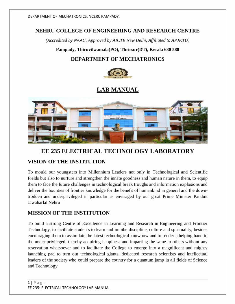
COURSE OUTCOME
CO 1 To acquire the basic knowledge in electric circuit theorems by experimental
verification.
CO 2 Understand 3 phase balanced and unbalanced, star and delta connected
supply and load and to measure power in 3 phase circuits
CO 3 Experimentally test the characteristics of DC machines under load and no
load condition.
CO 4 Acquire knowledge about the speed control of DC motors.
CO 5 Experimentally conduct the Swinburne‟s test and acquire the knowledge in
separation of losses in DC machines.
CO 6 Experimentally test the characteristics of single phase transformers under
load condition.
CO 7 Experimentally test the characteristics of Three phase Induction Motors
under load and no load condition.
CO VS PO’S AND PSO’S MAPPING
CO PO1 PO2 PO3 PO4 PO5 PO6 PO7 PO8 PO9 PO10 PO11 PO12 PS013 PSO14
CO 1 2 2 2 2 1 1
CO 2 2 1 2 2 1 1
CO 3 2 1 2 2 1 1
CO 4 2 1 2 2 1
CO 5 3 1 2 2 1
CO 6 3 2 2 2 1
CO 7 3 2 2 2 1
Note: H-Highly correlated=3, M-Medium correlated=2, L-Less correlated=1

DEPARTMENT OF MECHATRONICS, NCERC PAMPADY.
6 | P a g e EE 235: ELECTRICAL TECHNOLOGY LAB MANUAL
PREPARATION FOR THE LABORATORY SESSION
GENERAL INSTRUCTIONS TO STUDENTS
1. Read carefully and understand the descript ion of the experiment in the lab
manual. You may go to the lab at an earlier date to look at the experimental facilit y
and understand it better. Consult the appropriate references to be completely familiar with the
concepts and hardware.
2. Make sure that your observat ion for previous week experiment is evaluated by
the faculty member and your have transferred all the contents to your record before
entering to the lab/workshop.
3 . At t he be g inn ing o f t he c la ss , i f t he fa cu lt y o r t he in s t r u c t o r f ind s t ha t
a s t ude nt is no t adequately prepared, they will be marked as absent and not be
allowed to perform the experiment.
4. Bring necessary material needed (writ ing materials, graphs, calculators, etc.) to
perform the required preliminary analysis. It is a good idea to do sample calculations and as
much of the analysis as possible during the session. Faculty help will be available. Errors in
the procedure may thus be easily detected and rectified.
5. Please act ively part icipate in class and don‟t hesitate to ask quest ions. Please
utilize the teaching assistants fully. To encourage you to be prepared and to read
the lab manual before coming to the laboratory, unannounced questions may be asked at any
time during the lab.
6. Carelessness in personal conduct or in handling equipment may result in serious
injury to the individual or the equipment. Do not run near moving
machinery/equipment‟s. Always be on the alert for strange sounds. Guard against
entangling clothes in moving parts of machinery.
7 . S t udent s mu st fo l lo w t he p r o per d r es s co de ins id e t he la bo r a t o r y. T o
p r o t ec t c lo t h ing from dirt, wear a lab coat. Long hair should be tied back. Shoes covering
the whole foot will have to be worn.

DEPARTMENT OF MECHATRONICS, NCERC PAMPADY.
7 | P a g e EE 235: ELECTRICAL TECHNOLOGY LAB MANUAL
8 . I n pe r fo r ming t he e xper ime nt s , p l ea se p r o cee d ca r e fu l ly t o min imiz e
a ny wat e r s p i l ls , especially on the electric circuits and wire.
9 . Ma in t a in s i le nc e , o r der a nd d is c ip l ine in s id e t he la b. Do n‟t u se c e l l
pho ne s in s id e t he laboratory.
10. Any injury no matter how small must be reported to the instructor immediately.
11. Check with faculty members one week before the experiment to make sure that
you have the handout for that experiment and all the apparatus.
AFTER THE LABORATORY SESSION
1 . C l e a n u p y o u r w o r k a r e a .
2 . C hec k w it h t he t ec hn ic ia n be fo r e yo u lea ve .
3. Make sure you understand what kind of report is to be prepared and due
submission of record is next lab class.
4 . Do sa mp le ca lc u la t io ns a nd so me p r e l iminar y wo r k to ve r i f y t ha t
t he e xp er ime nt wa s successful
MAKE-UPS AND LATE WORK
Students must participate in all laboratory exercises as scheduled. They must obtain
permissionf r o m t h e f a c u l t y m e m b e r f o r a b s e n c e , w h i c h w o u l d b e g r a n
t e d o n l y u n d e r j u s t i f i a b l e circumstances. In such an event, a student must
make arrangements for a make-up laboratory, which will be scheduled when the time is
available after completing one cycle. Late submission will be awarded less mark for record
and internals and zero in worst cases.
LABORATORY POLICIES
1. Food, beverages & mobile phones are not allowed in the laboratory at any t ime.
2. Do not sit or place anything on instrument benches.
3. Organizing laboratory experiments requires the help of laboratory technicians
and staff. Be punctual.
DEPARTMENT OF MECHATRONICS, NCERC PAMPADY.
8 | P a g e EE 235: ELECTRICAL TECHNOLOGY LAB MANUAL
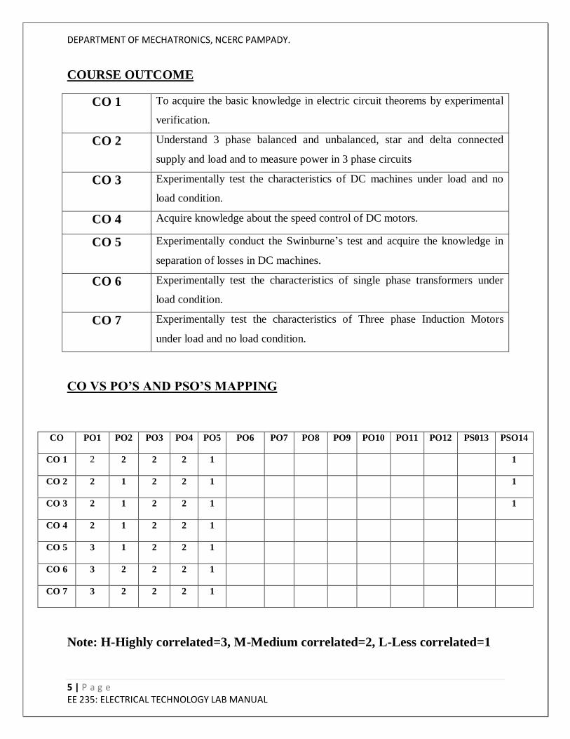
SYLLABUS
DEPARTMENT OF MECHATRONICS, NCERC PAMPADY.
9 | P a g e EE 235: ELECTRICAL TECHNOLOGY LAB MANUAL
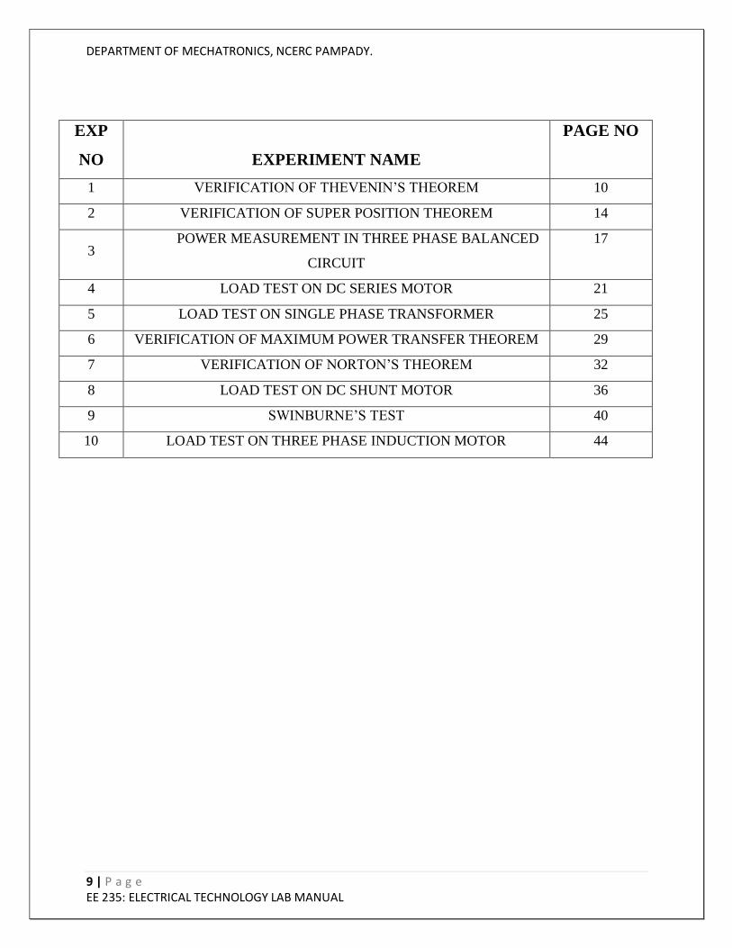
EXP
NO
EXPERIMENT NAME
PAGE NO
1 VERIFICATION OF THEVENIN‟S THEOREM 10
2 VERIFICATION OF SUPER POSITION THEOREM 14
3 POWER MEASUREMENT IN THREE PHASE BALANCED
CIRCUIT
17
4 LOAD TEST ON DC SERIES MOTOR 21
5 LOAD TEST ON SINGLE PHASE TRANSFORMER 25
6 VERIFICATION OF MAXIMUM POWER TRANSFER THEOREM 29
7 VERIFICATION OF NORTON‟S THEOREM 32
8 LOAD TEST ON DC SHUNT MOTOR 36
9 SWINBURNE‟S TEST 40
10 LOAD TEST ON THREE PHASE INDUCTION MOTOR 44
DEPARTMENT OF MECHATRONICS, NCERC PAMPADY.
10 | P a g e EE 235: ELECTRICAL TECHNOLOGY LAB MANUAL
1. VERIFICATION OF THEVENIN’S THEOREM
AIM
To verify Thevenin‟s theorem.
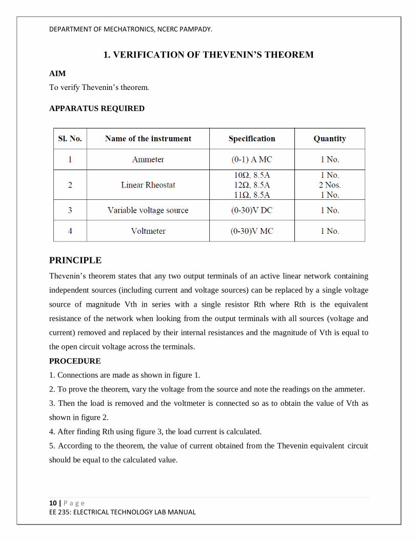
APPARATUS REQUIRED
PRINCIPLE
Thevenin‟s theorem states that any two output terminals of an active linear network containing
independent sources (including current and voltage sources) can be replaced by a single voltage
source of magnitude Vth in series with a single resistor Rth where Rth is the equivalent
resistance of the network when looking from the output terminals with all sources (voltage and
current) removed and replaced by their internal resistances and the magnitude of Vth is equal to
the open circuit voltage across the terminals.
PROCEDURE
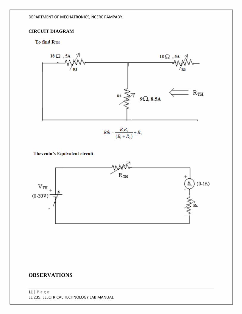
1. Connections are made as shown in figure 1.
2. To prove the theorem, vary the voltage from the source and note the readings on the ammeter.
3. Then the load is removed and the voltmeter is connected so as to obtain the value of Vth as
shown in figure 2.
4. After finding Rth using figure 3, the load current is calculated.
5. According to the theorem, the value of current obtained from the Thevenin equivalent circuit
should be equal to the calculated value.
DEPARTMENT OF MECHATRONICS, NCERC PAMPADY.
11 | P a g e EE 235: ELECTRICAL TECHNOLOGY LAB MANUAL
CIRCUIT DIAGRAM
OBSERVATIONS
DEPARTMENT OF MECHATRONICS, NCERC PAMPADY.
12 | P a g e EE 235: ELECTRICAL TECHNOLOGY LAB MANUAL
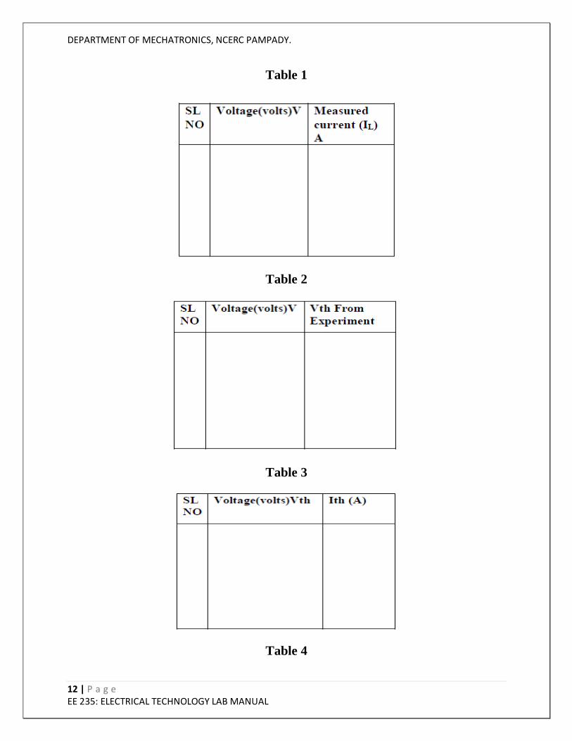
Table 1
Table 2
Table 3
Table 4
DEPARTMENT OF MECHATRONICS, NCERC PAMPADY.
13 | P a g e EE 235: ELECTRICAL TECHNOLOGY LAB MANUAL
RESULT AND DISCUSSION
CONCLUSION
VIVA QUESTIONS
1. What is Thevenin‟s theorem?
2. What are the advantages of Thevenin‟s theorem?
3. What is the difference between Thevenin‟s and Norton‟s theorem.
4. Differentiate between MI and MC meters.
5. What is source transformation technique?
DEPARTMENT OF MECHATRONICS, NCERC PAMPADY.
14 | P a g e EE 235: ELECTRICAL TECHNOLOGY LAB MANUAL
2. VERIFICATION OF SUPERPOSITION THEOREM
AIM
To verify superposition theorem.
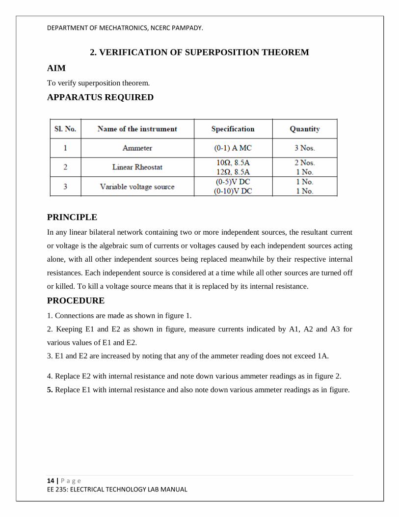
APPARATUS REQUIRED
PRINCIPLE
In any linear bilateral network containing two or more independent sources, the resultant current
or voltage is the algebraic sum of currents or voltages caused by each independent sources acting
alone, with all other independent sources being replaced meanwhile by their respective internal
resistances. Each independent source is considered at a time while all other sources are turned off
or killed. To kill a voltage source means that it is replaced by its internal resistance.
PROCEDURE
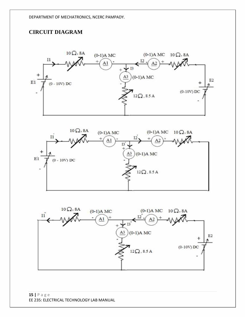
1. Connections are made as shown in figure 1.
2. Keeping E1 and E2 as shown in figure, measure currents indicated by A1, A2 and A3 for
various values of E1 and E2.
3. E1 and E2 are increased by noting that any of the ammeter reading does not exceed 1A.
4. Replace E2 with internal resistance and note down various ammeter readings as in figure 2.
5. Replace E1 with internal resistance and also note down various ammeter readings as in figure.
DEPARTMENT OF MECHATRONICS, NCERC PAMPADY.
15 | P a g e EE 235: ELECTRICAL TECHNOLOGY LAB MANUAL
CIRCUIT DIAGRAM

DEPARTMENT OF MECHATRONICS, NCERC PAMPADY.
16 | P a g e EE 235: ELECTRICAL TECHNOLOGY LAB MANUAL
OBSERVATIONS
SAMPLE CALCULATION
RESULT AND DISCUSSION
CONCLUSION
VIVA QUESTIONS
1. Explain superposition theorem.
2. What do you mean by killing a voltage source?
3. Explain Kirchhoff‟s voltage law.
4. Explain Kirchhoff‟s current law.
5. What do you mean by a linear bilateral network?

DEPARTMENT OF MECHATRONICS, NCERC PAMPADY.
17 | P a g e EE 235: ELECTRICAL TECHNOLOGY LAB MANUAL
3. POWER MEASUREMENT IN THREE PHASE BALANCED CIRCUIT
AIM
To measure the power and power factor of three phase balanced load by two wattmeter method.
APPARATUS REQUIRED
PRINCIPLE
In two wattmeter method the current coils of two watt meters are connected in two phases and
the potential coils between the corresponding phase and the third phase. It can be proved that the
sum of the wattmeter readings gives the total power.
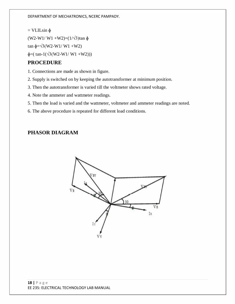
From the phasor diagram
Reading of Wattmeter 1, W1 = VRY IR cos(30 + ɸ)
Reading of Wattmeter 2, W2 = VBY IB cos(30 − ɸ)
W1 +W2= VRY IR(cos 30 cos ɸ − sin 30 sin ɸ) + VBY IB(cos 30 cos ɸ + sin 30 sin ɸ)
= VRY IR (cos 30 cos ɸ) + VBY IB(cos 30 cos ɸ)
Assuming balanced load
VRY = VBY = VBR = VL & IR = IB = IY = IL
Where VL and IL are the line values of voltage and current.
= VLIL cos 30 cos ɸ + VLIL cos 30 cos ɸ
= 2VLIL √3/2cos ɸ
=√3VLIL cos ɸ
W2-W1 = VLIL(cos(30 - ɸ) - cos (30 + ɸ))
DEPARTMENT OF MECHATRONICS, NCERC PAMPADY.
18 | P a g e EE 235: ELECTRICAL TECHNOLOGY LAB MANUAL
= VLILsin ɸ
(W2-W1/ W1 +W2)=(1/√3)tan ɸ
tan ɸ=√3(W2-W1/ W1 +W2)
ɸ=( tan-1(√3(W2-W1/ W1 +W2)))
PROCEDURE
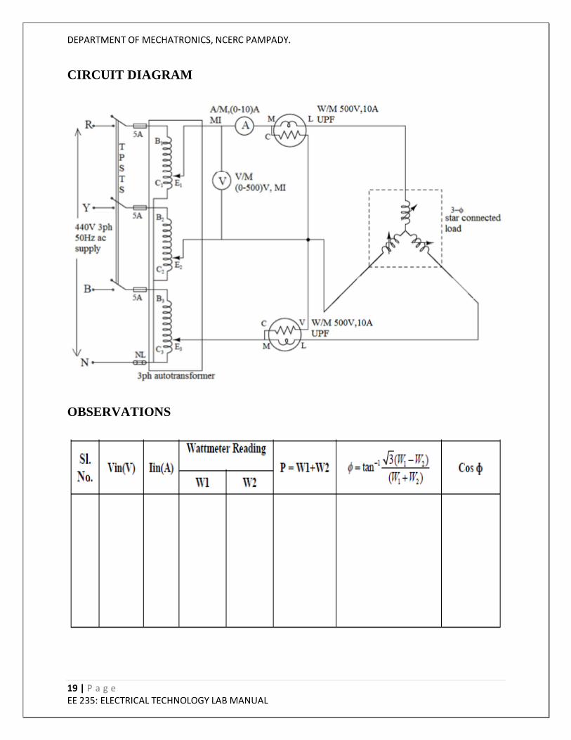
1. Connections are made as shown in figure.
2. Supply is switched on by keeping the autotransformer at minimum position.
3. Then the autotransformer is varied till the voltmeter shows rated voltage.
4. Note the ammeter and wattmeter readings.
5. Then the load is varied and the wattmeter, voltmeter and ammeter readings are noted.
6. The above procedure is repeated for different load conditions.
PHASOR DIAGRAM
DEPARTMENT OF MECHATRONICS, NCERC PAMPADY.
19 | P a g e EE 235: ELECTRICAL TECHNOLOGY LAB MANUAL
CIRCUIT DIAGRAM
OBSERVATIONS

DEPARTMENT OF MECHATRONICS, NCERC PAMPADY.
20 | P a g e EE 235: ELECTRICAL TECHNOLOGY LAB MANUAL
SAMPLE CALCULATION
Voltage V = . . . . . . . . .
Current I = . . . . . . . . .
Wattmeter reading W1 = . . . . . . . . .
Wattmeter reading W2 = . . . . . . . . .
Total power P = W1 +W2 = . . . . . . . . .
RESULT AND DISCUSSION
CONCLUSION
VIVA QUESTIONS
1. What is the expression for power in a 3ɸ circuit?
2. Derive the expression for power factor in terms of the wattmeter readings.
3. What are the other methods of measuring 3ɸ power?
4. What does a zero reading in one of the watt meters signify?
DEPARTMENT OF MECHATRONICS, NCERC PAMPADY.
21 | P a g e EE 235: ELECTRICAL TECHNOLOGY LAB MANUAL
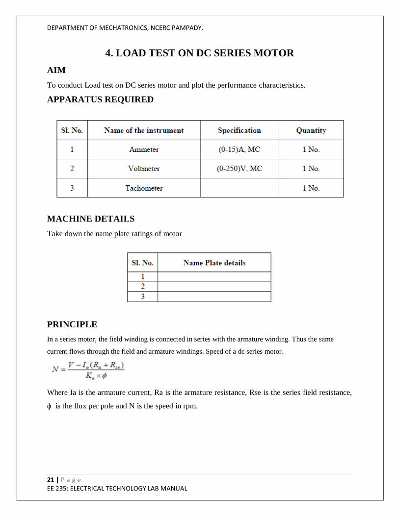
4. LOAD TEST ON DC SERIES MOTOR
AIM
To conduct Load test on DC series motor and plot the performance characteristics.
APPARATUS REQUIRED
MACHINE DETAILS
Take down the name plate ratings of motor
PRINCIPLE
In a series motor, the field winding is connected in series with the armature winding. Thus the same
current flows through the field and armature windings. Speed of a dc series motor.
Where Ia is the armature current, Ra is the armature resistance, Rse is the series field resistance,
ɸ is the flux per pole and N is the speed in rpm.
DEPARTMENT OF MECHATRONICS, NCERC PAMPADY.
22 | P a g e EE 235: ELECTRICAL TECHNOLOGY LAB MANUAL
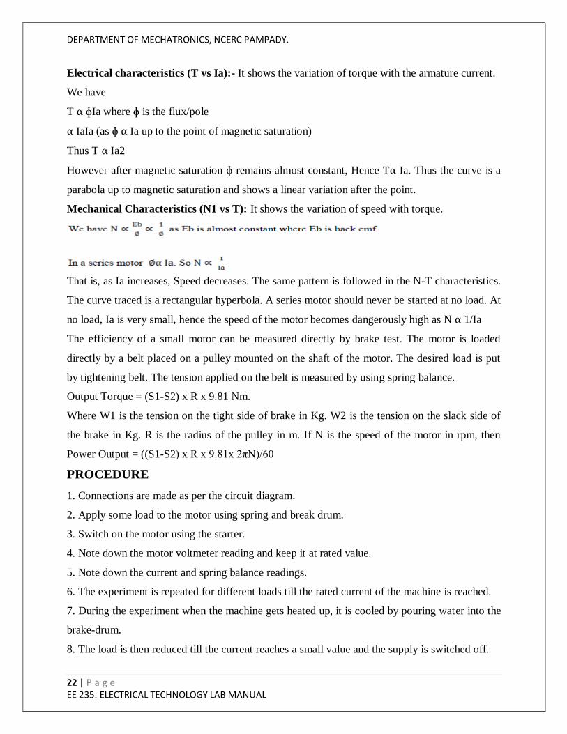
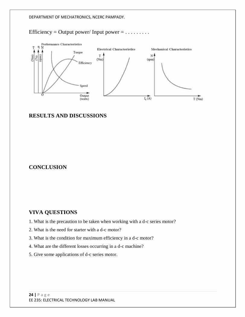
Electrical characteristics (T vs Ia):- It shows the variation of torque with the armature current.
We have
T ⍺ ɸIa where ɸ is the flux/pole
⍺ IaIa (as ɸ ⍺ Ia up to the point of magnetic saturation)
Thus T ⍺ Ia2
However after magnetic saturation ɸ remains almost constant, Hence T⍺ Ia. Thus the curve is a
parabola up to magnetic saturation and shows a linear variation after the point.
Mechanical Characteristics (N1 vs T): It shows the variation of speed with torque.
That is, as Ia increases, Speed decreases. The same pattern is followed in the N-T characteristics.
The curve traced is a rectangular hyperbola. A series motor should never be started at no load. At
no load, Ia is very small, hence the speed of the motor becomes dangerously high as N ⍺ 1/Ia
The efficiency of a small motor can be measured directly by brake test. The motor is loaded
directly by a belt placed on a pulley mounted on the shaft of the motor. The desired load is put
by tightening belt. The tension applied on the belt is measured by using spring balance.
Output Torque = (S1-S2) x R x 9.81 Nm.
Where W1 is the tension on the tight side of brake in Kg. W2 is the tension on the slack side of
the brake in Kg. R is the radius of the pulley in m. If N is the speed of the motor in rpm, then
Power Output = ((S1-S2) x R x 9.81x 2πN)/60
PROCEDURE
1. Connections are made as per the circuit diagram.
2. Apply some load to the motor using spring and break drum.
3. Switch on the motor using the starter.
4. Note down the motor voltmeter reading and keep it at rated value.
5. Note down the current and spring balance readings.
6. The experiment is repeated for different loads till the rated current of the machine is reached.
7. During the experiment when the machine gets heated up, it is cooled by pouring water into the
brake-drum.
8. The load is then reduced till the current reaches a small value and the supply is switched off.
DEPARTMENT OF MECHATRONICS, NCERC PAMPADY.
23 | P a g e EE 235: ELECTRICAL TECHNOLOGY LAB MANUAL
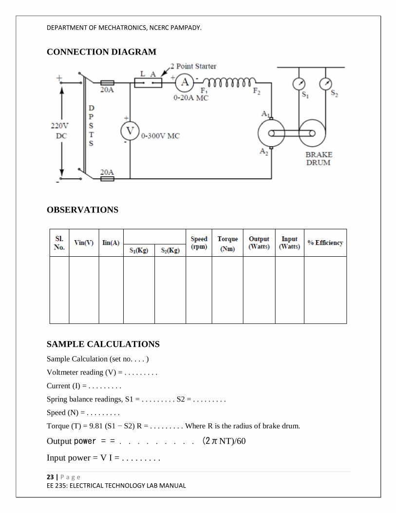
CONNECTION DIAGRAM
OBSERVATIONS
SAMPLE CALCULATIONS
Sample Calculation (set no. . . . )
Voltmeter reading (V) = . . . . . . . . .
Current (I) = . . . . . . . . .
Spring balance readings, S1 = . . . . . . . . . S2 = . . . . . . . . .
Speed (N) = . . . . . . . . .
Torque (T) = 9.81 (S1 − S2) R = . . . . . . . . . Where R is the radius of brake drum.
Output power = = . . . . . . . . . (2πNT)/60
Input power = V I = . . . . . . . . .
DEPARTMENT OF MECHATRONICS, NCERC PAMPADY.
24 | P a g e EE 235: ELECTRICAL TECHNOLOGY LAB MANUAL
Efficiency = Output power/ Input power = . . . . . . . . .
RESULTS AND DISCUSSIONS
CONCLUSION
VIVA QUESTIONS
1. What is the precaution to be taken when working with a d-c series motor?
2. What is the need for starter with a d-c motor?
3. What is the condition for maximum efficiency in a d-c motor?
4. What are the different losses occurring in a d-c machine?
5. Give some applications of d-c series motor.
DEPARTMENT OF MECHATRONICS, NCERC PAMPADY.
25 | P a g e EE 235: ELECTRICAL TECHNOLOGY LAB MANUAL
5. LOAD TEST ON SINGLE PHASE TRANSFORMER
AIM
To conduct load test on the given single phase transformer at unity power factor and determine
the efficiency and regulation curve.
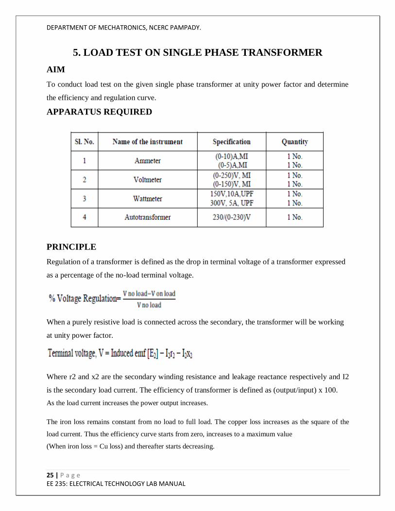
APPARATUS REQUIRED
PRINCIPLE
Regulation of a transformer is defined as the drop in terminal voltage of a transformer expressed
as a percentage of the no-load terminal voltage.
When a purely resistive load is connected across the secondary, the transformer will be working
at unity power factor.
Where r2 and x2 are the secondary winding resistance and leakage reactance respectively and I2
is the secondary load current. The efficiency of transformer is defined as (output/input) x 100.
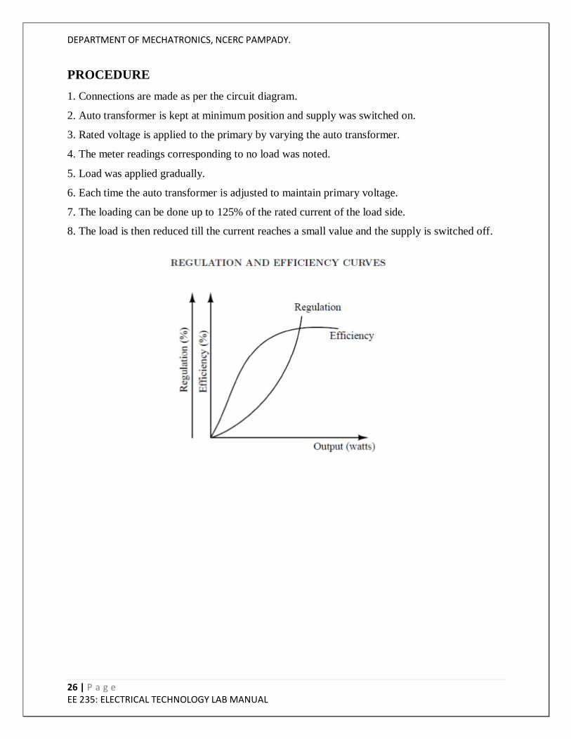
As the load current increases the power output increases.
The iron loss remains constant from no load to full load. The copper loss increases as the square of the
load current. Thus the efficiency curve starts from zero, increases to a maximum value
(When iron loss = Cu loss) and thereafter starts decreasing.
DEPARTMENT OF MECHATRONICS, NCERC PAMPADY.
26 | P a g e EE 235: ELECTRICAL TECHNOLOGY LAB MANUAL
PROCEDURE
1. Connections are made as per the circuit diagram.
2. Auto transformer is kept at minimum position and supply was switched on.
3. Rated voltage is applied to the primary by varying the auto transformer.
4. The meter readings corresponding to no load was noted.
5. Load was applied gradually.
6. Each time the auto transformer is adjusted to maintain primary voltage.
7. The loading can be done up to 125% of the rated current of the load side.
8. The load is then reduced till the current reaches a small value and the supply is switched off.
DEPARTMENT OF MECHATRONICS, NCERC PAMPADY.
27 | P a g e EE 235: ELECTRICAL TECHNOLOGY LAB MANUAL
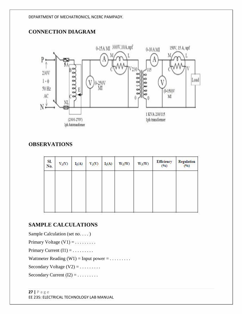
CONNECTION DIAGRAM
OBSERVATIONS
SAMPLE CALCULATIONS
Sample Calculation (set no. . . . )
Primary Voltage (V1) = . . . . . . . . .
Primary Current (I1) = . . . . . . . . .
Wattmeter Reading (W1) = Input power = . . . . . . . . .
Secondary Voltage (V2) = . . . . . . . . .
Secondary Current (I2) = . . . . . . . . .

DEPARTMENT OF MECHATRONICS, NCERC PAMPADY.
28 | P a g e EE 235: ELECTRICAL TECHNOLOGY LAB MANUAL
Wattmeter Reading (W2) = Output power = . . . . . . . . .
Efficiency = (Output power/Input power) ×100= . . . . . . . . .
Regulation = (VNL – VL)/VNL ×100 = . . . . . . . . .
VNL = V2NL
VL=V2FL
RESULT AND DISCUSSION
CONCLUSION
VIVA QUESTIONS
1. What do you understand by regulation of a transformer?
2. What are the other methods of testing transformers?
3. What is the disadvantage of testing a transformer using load test?
4. Is a high or low value of regulation preferred for a transformer? Give reasons.
5. What are the reasons for the drop in terminal voltage as the secondary current is increased?
DEPARTMENT OF MECHATRONICS, NCERC PAMPADY.
29 | P a g e EE 235: ELECTRICAL TECHNOLOGY LAB MANUAL
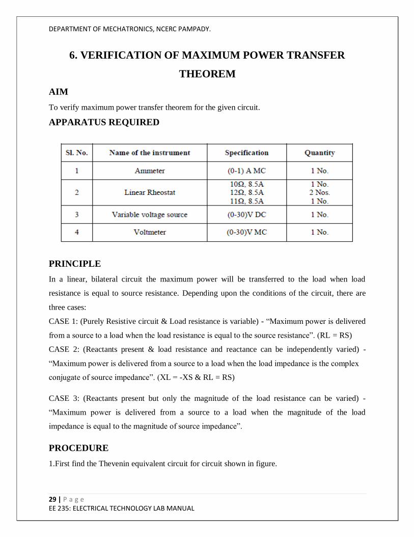
6. VERIFICATION OF MAXIMUM POWER TRANSFER
THEOREM
AIM
To verify maximum power transfer theorem for the given circuit.
APPARATUS REQUIRED
PRINCIPLE
In a linear, bilateral circuit the maximum power will be transferred to the load when load
resistance is equal to source resistance. Depending upon the conditions of the circuit, there are
three cases:
CASE 1: (Purely Resistive circuit & Load resistance is variable) - “Maximum power is delivered
from a source to a load when the load resistance is equal to the source resistance”. (RL = RS)
CASE 2: (Reactants present & load resistance and reactance can be independently varied) -
“Maximum power is delivered from a source to a load when the load impedance is the complex
conjugate of source impedance”. (XL = -XS & RL = RS)
CASE 3: (Reactants present but only the magnitude of the load resistance can be varied) -
“Maximum power is delivered from a source to a load when the magnitude of the load
impedance is equal to the magnitude of source impedance”.
PROCEDURE
1.First find the Thevenin equivalent circuit for circuit shown in figure.
DEPARTMENT OF MECHATRONICS, NCERC PAMPADY.
30 | P a g e EE 235: ELECTRICAL TECHNOLOGY LAB MANUAL
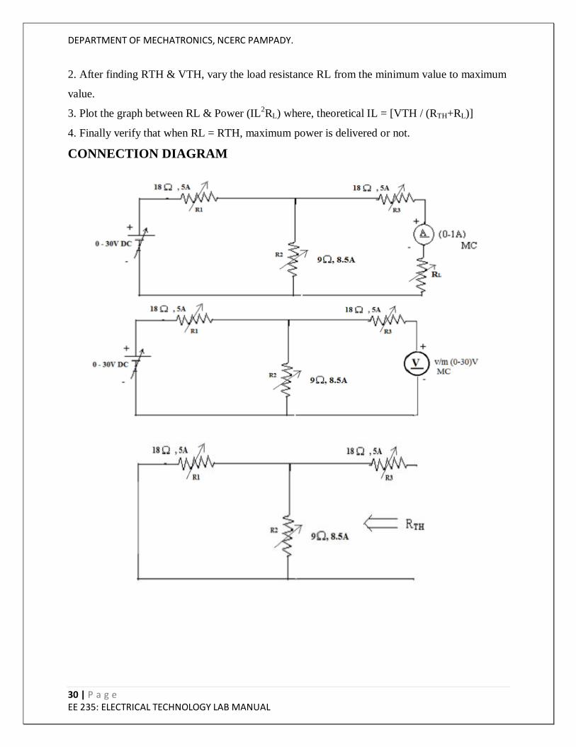
2. After finding RTH & VTH, vary the load resistance RL from the minimum value to maximum
value.
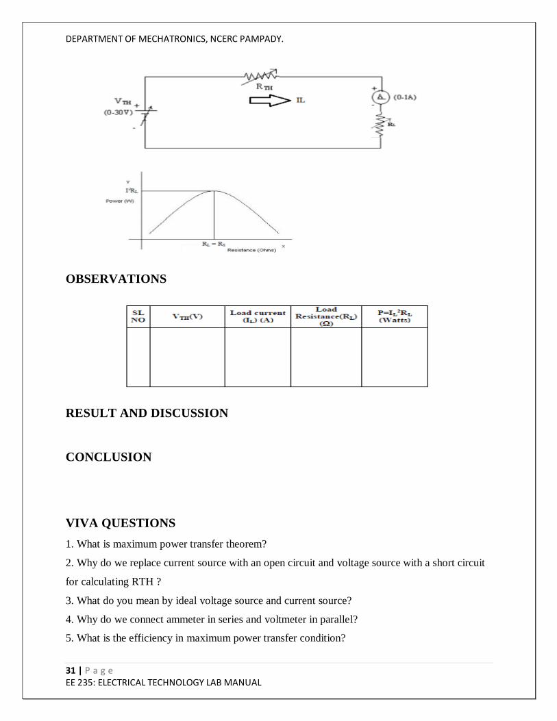
3. Plot the graph between RL & Power (IL2RL) where, theoretical IL = [VTH / (RTH+RL)]
4. Finally verify that when RL = RTH, maximum power is delivered or not.
CONNECTION DIAGRAM
DEPARTMENT OF MECHATRONICS, NCERC PAMPADY.
31 | P a g e EE 235: ELECTRICAL TECHNOLOGY LAB MANUAL
OBSERVATIONS
RESULT AND DISCUSSION
CONCLUSION
VIVA QUESTIONS
1. What is maximum power transfer theorem?
2. Why do we replace current source with an open circuit and voltage source with a short circuit
for calculating RTH ?
3. What do you mean by ideal voltage source and current source?
4. Why do we connect ammeter in series and voltmeter in parallel?
5. What is the efficiency in maximum power transfer condition?
DEPARTMENT OF MECHATRONICS, NCERC PAMPADY.
32 | P a g e EE 235: ELECTRICAL TECHNOLOGY LAB MANUAL
7. VERIFICATION OF NORTON’S THEOREM
AIM
To find the Norton‟s equivalent circuit from the given circuit.
APPARATUS REQUIRED
PRINCIPLE
Norton‟s theorem states that any two terminal linear network with current sources, voltage
sources and resistances can be replaced by an equivalent circuit consisting of a current source in
parallel with a resistance. The value of the current source is the short circuit current between the
two terminals of the network and the resistance is equal to the equivalent resistance measured
between the terminals with all the energy sources are replaced by their internal resistances.
PROCEDURE
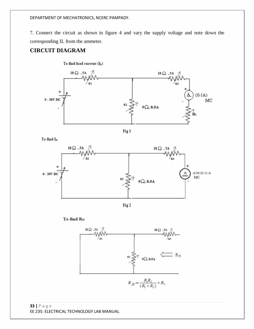
1. Connection are made as per the circuit diagram shown in figure 1.
2. Vary the supply voltage V and take the corresponding reading IL from the ammeter.
3. Now connect the circuit diagram in figure 2 (Removing the load resistor RL and shorting the
terminals).
4. Vary the supply voltage V in the same way as done in step 2 and note down the corresponding
IN from the ammeter.
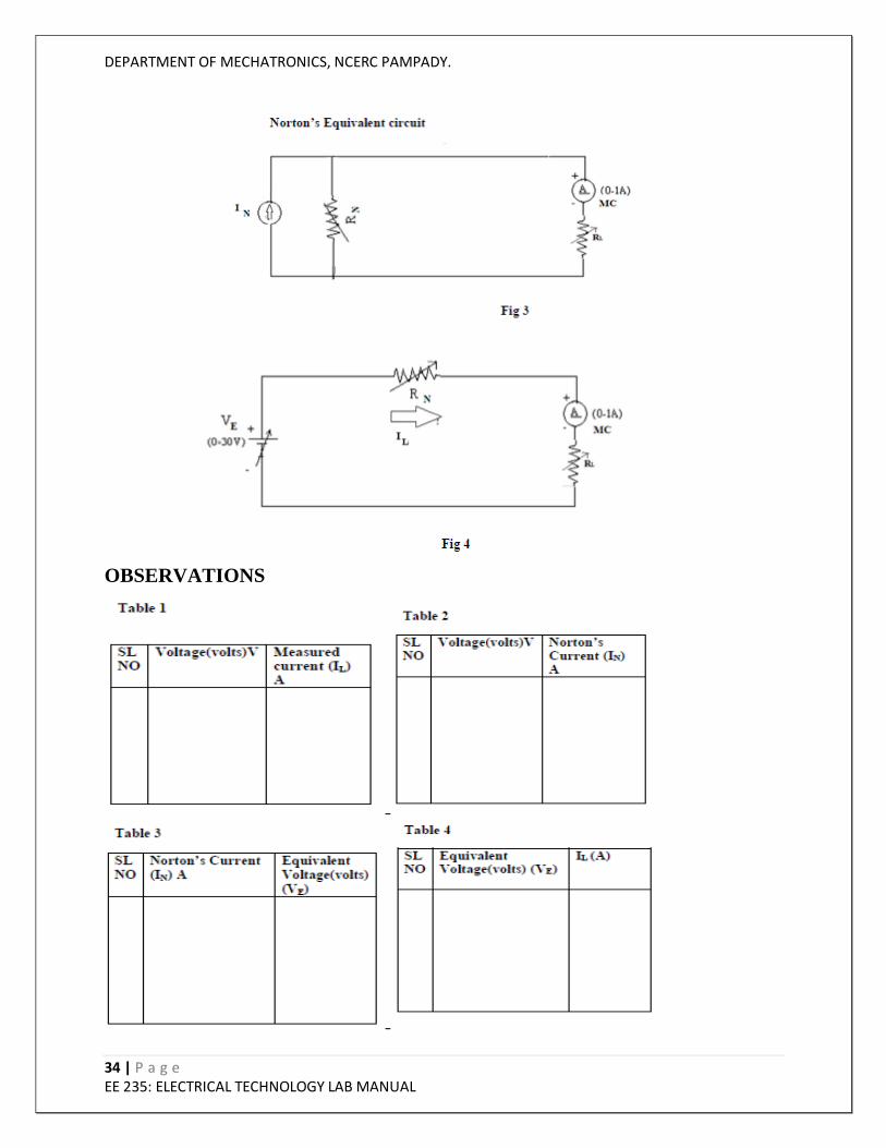
5. Find out the RN and draw the Norton‟s Equivalent circuit.
6. Now apply source transformation in the circuit diagram as shown in figure 3 and obtain the
circuit as shown in figure 4.
DEPARTMENT OF MECHATRONICS, NCERC PAMPADY.
33 | P a g e EE 235: ELECTRICAL TECHNOLOGY LAB MANUAL
7. Connect the circuit as shown in figure 4 and vary the supply voltage and note down the
corresponding IL from the ammeter.
CIRCUIT DIAGRAM
DEPARTMENT OF MECHATRONICS, NCERC PAMPADY.
34 | P a g e EE 235: ELECTRICAL TECHNOLOGY LAB MANUAL
OBSERVATIONS

DEPARTMENT OF MECHATRONICS, NCERC PAMPADY.
35 | P a g e EE 235: ELECTRICAL TECHNOLOGY LAB MANUAL
RESULT AND DISCUSSION
CONCLUSION
VIVA QUESTIONS
1. What is Norton‟s theorem?
2. What are the advantages of Norton‟s theorem?
3. What is the difference between Thevenin‟s and Norton‟s theorem.
4. Differentiate between dependent and independent sources.
5. What is internal resistance of a source?
DEPARTMENT OF MECHATRONICS, NCERC PAMPADY.
36 | P a g e EE 235: ELECTRICAL TECHNOLOGY LAB MANUAL
8.LOAD TEST ON DC SHUNT MOTOR
AIM
To conduct Load test on DC shunt motor and plot its performance characteristics.
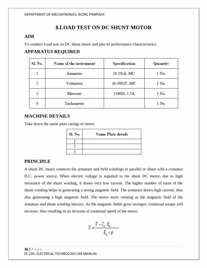
APPARATUS REQUIRED
MACHINE DETAILS
Take down the name plate ratings of motor
PRINCIPLE
A shunt DC motor connects the armature and field windings in parallel or shunt with a common
D.C. power source. When electric voltage is supplied to the shunt DC motor, due to high
resistance of the shunt winding, it draws very low current. The higher number of turns of the
shunt winding helps in generating a strong magnetic field. The armature draws high current, thus
also generating a high magnetic field. The motor starts rotating as the magnetic field of the
armature and shunt winding interact. As the magnetic fields grow stronger, rotational torque will
increase, thus resulting in an increase of rotational speed of the motor.
DEPARTMENT OF MECHATRONICS, NCERC PAMPADY.
37 | P a g e EE 235: ELECTRICAL TECHNOLOGY LAB MANUAL
Where Ia is the armature current, Ra is the armature resistance, ɸ is the flux per pole and N is the
speed in rpm.
Output Torque = (S1-S2) x R x 9.81 Nm
Where W1 is the tension on the tight side of brake in Kg. W2 is the tension on the slack side of
the brake in Kg. R is the radius of the pulley in m. If N is the speed of the motor in rpm, then
Power Output = ((S1-S2) x R x 9.81x 2πN)/60
PRECAUTIONS:
1. DC shunt motor should be started and stopped under no load condition.
2. Field rheostat should be kept in the minimum position.
3. Brake drum should be cooled with water when it is under load.
PROCEDURE
1.Connections are made as per the circuit diagram.
2.After checking the no load condition, and minimum field rheostat position, DPST switch is
closed and starter resistance is gradually removed.
3.The motor is brought to its rated speed by adjusting the field rheostat.
4.Ammeter, Voltmeter readings, speed and spring balance readings are noted under no load
condition.
5.The load is then added to the motor gradually and for each load, voltmeter, ammeter, spring
balance readings and speed of the motor are noted.
6.The motor is then brought to no load condition and field rheostat to minimum position, then
DPST switch is opened.
DEPARTMENT OF MECHATRONICS, NCERC PAMPADY.
38 | P a g e EE 235: ELECTRICAL TECHNOLOGY LAB MANUAL
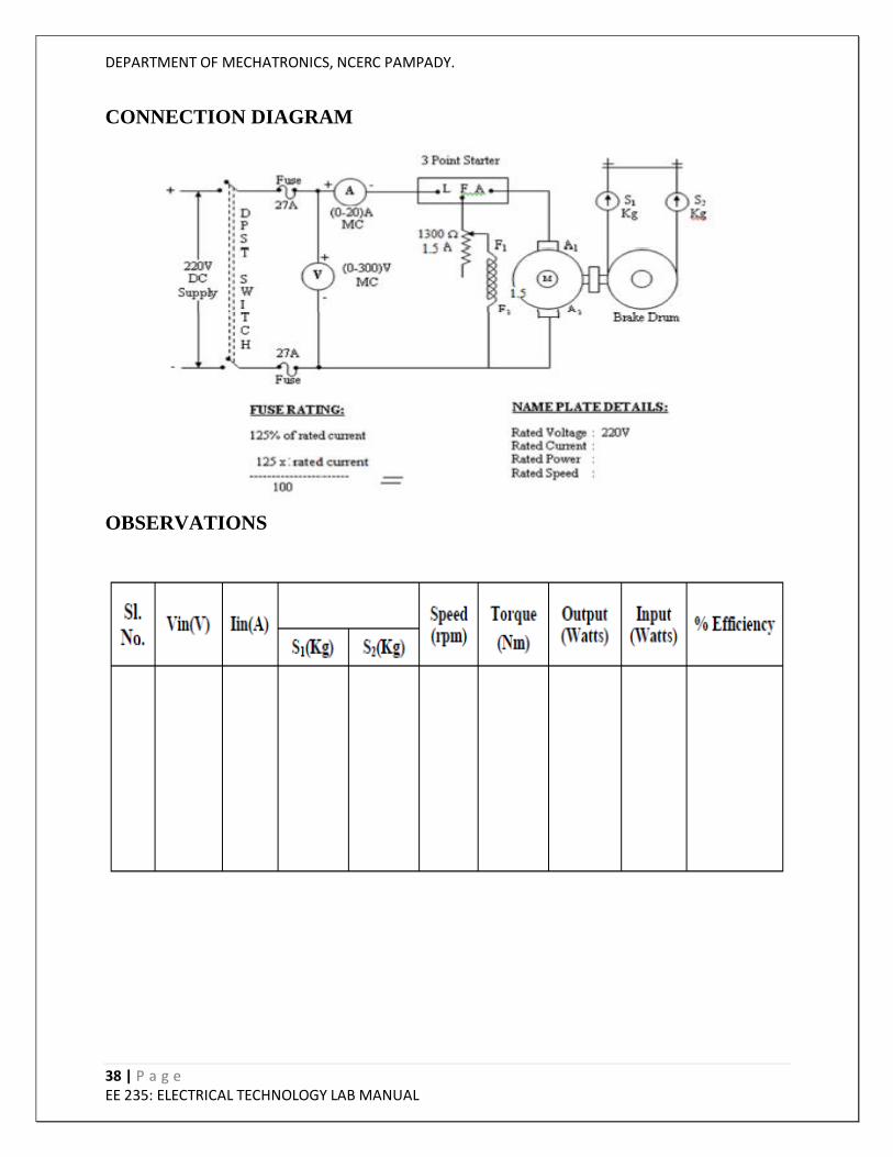
CONNECTION DIAGRAM
OBSERVATIONS
DEPARTMENT OF MECHATRONICS, NCERC PAMPADY.
39 | P a g e EE 235: ELECTRICAL TECHNOLOGY LAB MANUAL
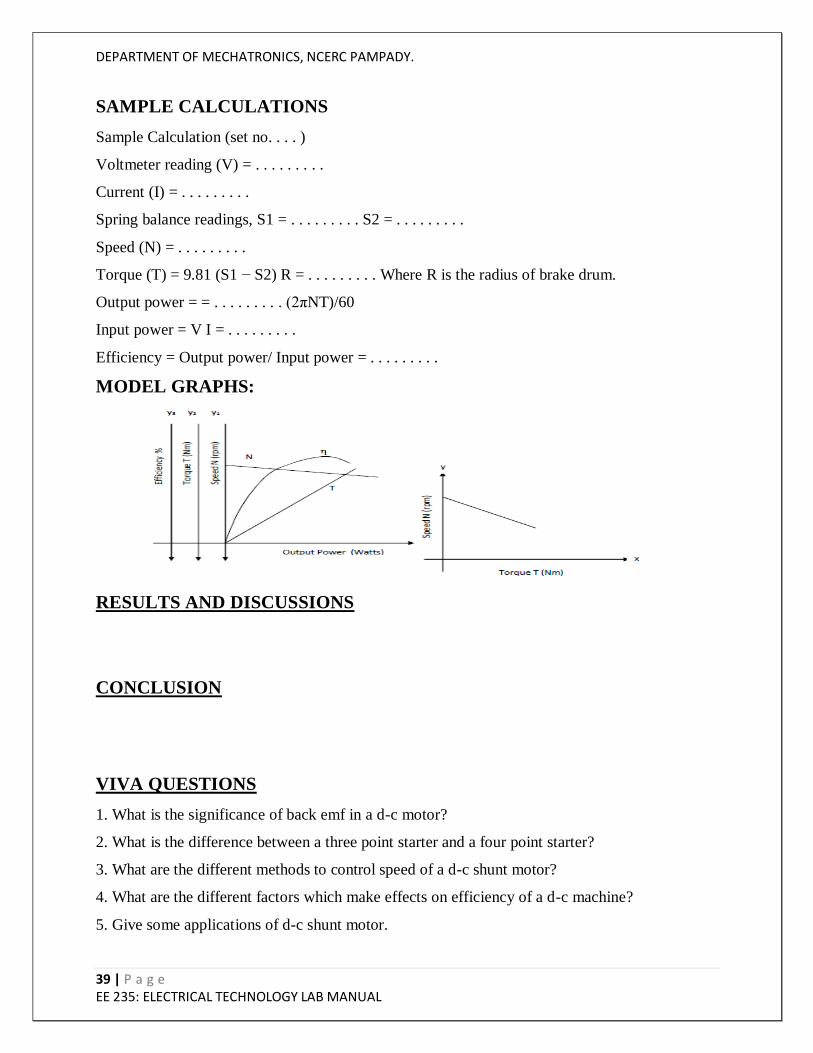
SAMPLE CALCULATIONS
Sample Calculation (set no. . . . )
Voltmeter reading (V) = . . . . . . . . .
Current (I) = . . . . . . . . .
Spring balance readings, S1 = . . . . . . . . . S2 = . . . . . . . . .
Speed (N) = . . . . . . . . .
Torque (T) = 9.81 (S1 − S2) R = . . . . . . . . . Where R is the radius of brake drum.
Output power = = . . . . . . . . . (2πNT)/60
Input power = V I = . . . . . . . . .
Efficiency = Output power/ Input power = . . . . . . . . .
MODEL GRAPHS:
RESULTS AND DISCUSSIONS
CONCLUSION
VIVA QUESTIONS
1. What is the significance of back emf in a d-c motor?
2. What is the difference between a three point starter and a four point starter?
3. What are the different methods to control speed of a d-c shunt motor?
4. What are the different factors which make effects on efficiency of a d-c machine?
5. Give some applications of d-c shunt motor.
DEPARTMENT OF MECHATRONICS, NCERC PAMPADY.
40 | P a g e EE 235: ELECTRICAL TECHNOLOGY LAB MANUAL
9.SWINBURNE’S TEST
AIM
To conduct Swinburne‟s test on DC machine to determine efficiency when working as generator
and motor without actually loading the machine and predetermine the armature current and
efficiency when the machine operates as a motor and as a generator at (1/4)th full load , (1/2) full
load, (3/4)th full load, full load and (5/4)th full load.
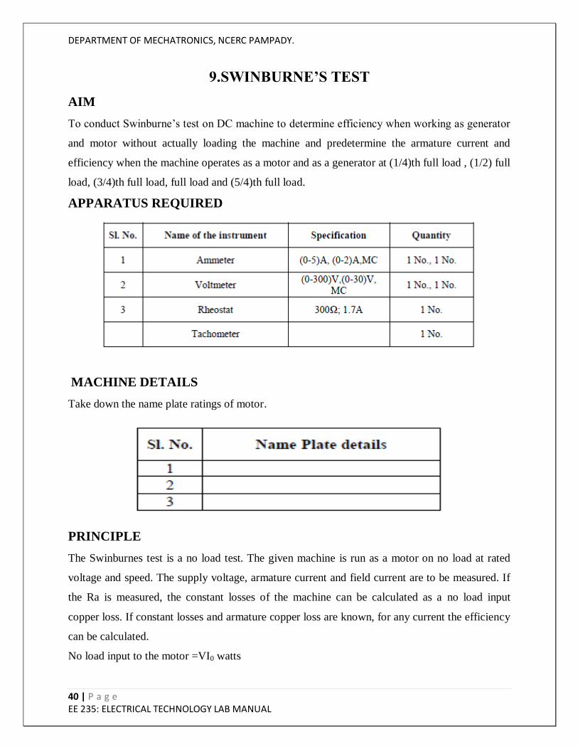
APPARATUS REQUIRED
MACHINE DETAILS
Take down the name plate ratings of motor.
PRINCIPLE
The Swinburnes test is a no load test. The given machine is run as a motor on no load at rated
voltage and speed. The supply voltage, armature current and field current are to be measured. If
the Ra is measured, the constant losses of the machine can be calculated as a no load input
copper loss. If constant losses and armature copper loss are known, for any current the efficiency
can be calculated.
No load input to the motor =VI0 watts
DEPARTMENT OF MECHATRONICS, NCERC PAMPADY.
41 | P a g e EE 235: ELECTRICAL TECHNOLOGY LAB MANUAL
Armature copper loss at no load= Ia02Ra
Constant loss of the machine , Wc=VI0-Ia02Ra-VbIa0
Input to generator at full load= Output+Wc+Cu loss + brush loss
Input to motor at full load =VIl
Efficiency= (Output/Input)*100
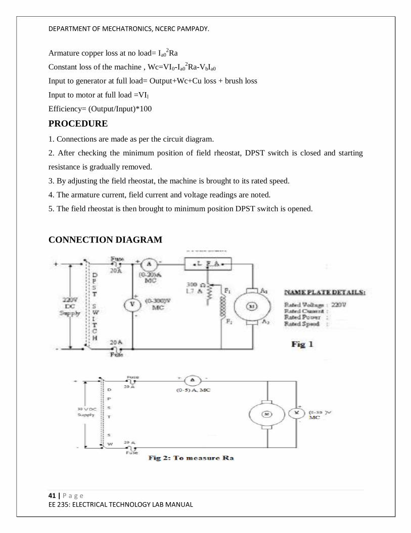
PROCEDURE
1. Connections are made as per the circuit diagram.
2. After checking the minimum position of field rheostat, DPST switch is closed and starting
resistance is gradually removed.
3. By adjusting the field rheostat, the machine is brought to its rated speed.
4. The armature current, field current and voltage readings are noted.
5. The field rheostat is then brought to minimum position DPST switch is opened.
CONNECTION DIAGRAM
DEPARTMENT OF MECHATRONICS, NCERC PAMPADY.
42 | P a g e EE 235: ELECTRICAL TECHNOLOGY LAB MANUAL
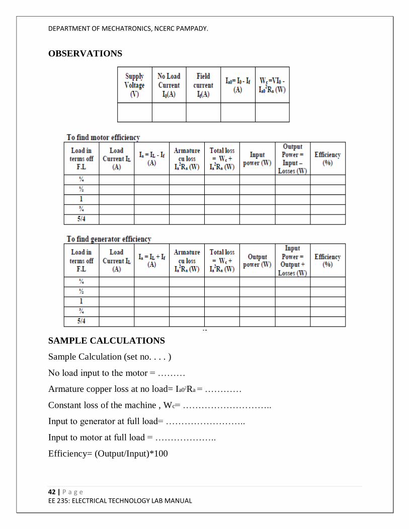
OBSERVATIONS
SAMPLE CALCULATIONS
Sample Calculation (set no. . . . )
No load input to the motor = ………
Armature copper loss at no load= Ia02Ra = …………
Constant loss of the machine , Wc= ………………………..
Input to generator at full load= ……………………..
Input to motor at full load = ………………..
Efficiency= (Output/Input)*100
DEPARTMENT OF MECHATRONICS, NCERC PAMPADY.
43 | P a g e EE 235: ELECTRICAL TECHNOLOGY LAB MANUAL
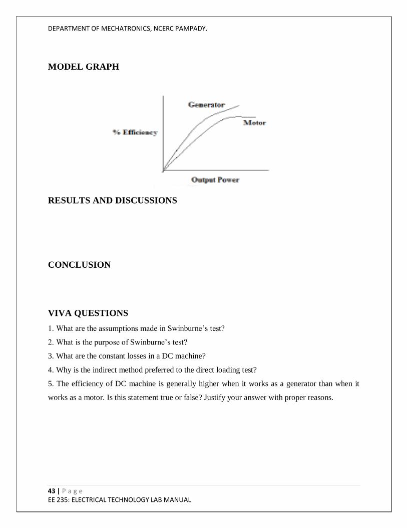
MODEL GRAPH
RESULTS AND DISCUSSIONS
CONCLUSION
VIVA QUESTIONS
1. What are the assumptions made in Swinburne‟s test?
2. What is the purpose of Swinburne‟s test?
3. What are the constant losses in a DC machine?
4. Why is the indirect method preferred to the direct loading test?
5. The efficiency of DC machine is generally higher when it works as a generator than when it
works as a motor. Is this statement true or false? Justify your answer with proper reasons.
DEPARTMENT OF MECHATRONICS, NCERC PAMPADY.
44 | P a g e EE 235: ELECTRICAL TECHNOLOGY LAB MANUAL
10. LOAD TEST ON THREE PHASE INDUCTION MOTOR
AIM
To conduct load test on the given 3-ph squirrel cage induction motor and plot the performance
characteristics.
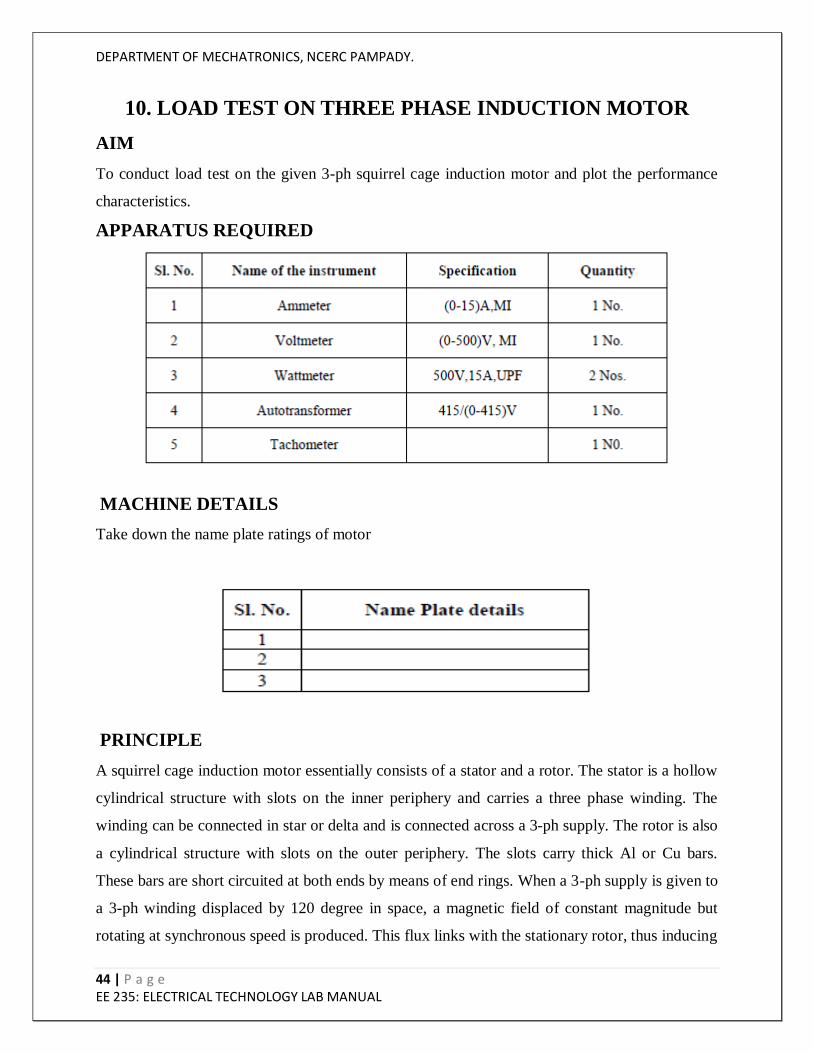
APPARATUS REQUIRED
MACHINE DETAILS
Take down the name plate ratings of motor
PRINCIPLE
A squirrel cage induction motor essentially consists of a stator and a rotor. The stator is a hollow
cylindrical structure with slots on the inner periphery and carries a three phase winding. The
winding can be connected in star or delta and is connected across a 3-ph supply. The rotor is also
a cylindrical structure with slots on the outer periphery. The slots carry thick Al or Cu bars.
These bars are short circuited at both ends by means of end rings. When a 3-ph supply is given to
a 3-ph winding displaced by 120 degree in space, a magnetic field of constant magnitude but
rotating at synchronous speed is produced. This flux links with the stationary rotor, thus inducing
DEPARTMENT OF MECHATRONICS, NCERC PAMPADY.
45 | P a g e EE 235: ELECTRICAL TECHNOLOGY LAB MANUAL
an emf in it. As the rotor circuit is closed, a current flows through it. The direction of the induced
current is such as to oppose the cause producing it. The cause is the relative motion between the
stator magnetic field and the rotor. So the rotor starts rotating in the same direction as the stator
magnetic field and tries to catch up with it. But practically it is never able to do so. Because if it
does so, there would be no relative motion, no emf and hence no torque.
Thus an induction motor always runs at a speed slightly less than the synchronous speed. The
term slip is of importance in an induction motor and is defined as
%slip =((Ns – N)/Ns)∗100
Where, Ns - Synchronous speed =120 × f𝑃
N - rotor speed
f - frequency
P - No. of poles of the machine
An induction motor can never operate at s=0. It always operates between s=0 and s=1(starting).
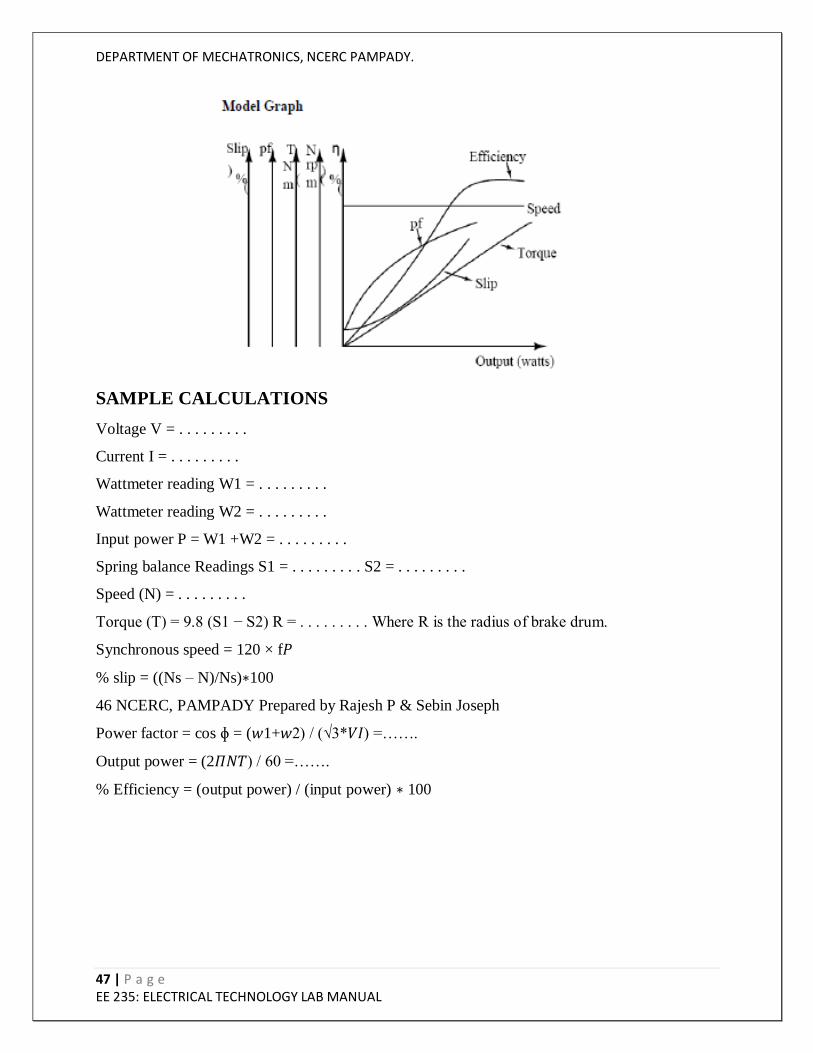
The performance characteristics are plots of efficiency, torque, speed, slip, pf and line current
versus output.
Current and torque increases with increase in output. The induction motor is essentially a
constant speed motor. However speed reduces gradually with increase in output and slip
increases gradually with increase in output. The pf is low at low
loads and increases with increase in output. The efficiency increases with increase in output,
reaches a peak value and then gradually drops with further increase in output.
PROCEDURE
1. Connections are made as shown in figure.
2. Close the TPST switch.
3. Adjust the 3phase autotransformer till the voltmeter shows the rated line voltage of the
induction motor.
4. Note down the line voltage, line current, power input and the speed indicated by the respective
voltmeter, ammeter, wattmeter and tachometer under no load condition.
5. Load the machine by means of brake drum arrangement and note down the corresponding
meter readings and speed.
6. Repeat the same procedure up to the rated current of the induction motor.
DEPARTMENT OF MECHATRONICS, NCERC PAMPADY.
46 | P a g e EE 235: ELECTRICAL TECHNOLOGY LAB MANUAL
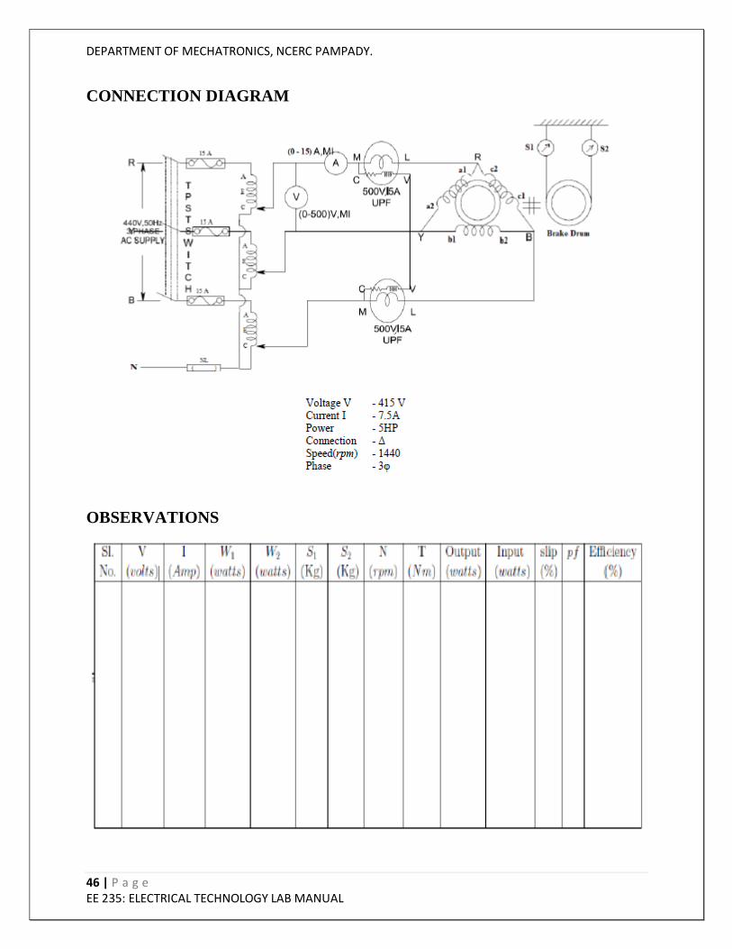
CONNECTION DIAGRAM
OBSERVATIONS
DEPARTMENT OF MECHATRONICS, NCERC PAMPADY.
47 | P a g e EE 235: ELECTRICAL TECHNOLOGY LAB MANUAL
SAMPLE CALCULATIONS
Voltage V = . . . . . . . . .
Current I = . . . . . . . . .
Wattmeter reading W1 = . . . . . . . . .
Wattmeter reading W2 = . . . . . . . . .
Input power P = W1 +W2 = . . . . . . . . .
Spring balance Readings S1 = . . . . . . . . . S2 = . . . . . . . . .
Speed (N) = . . . . . . . . .
Torque (T) = 9.8 (S1 − S2) R = . . . . . . . . . Where R is the radius of brake drum.
Synchronous speed = 120 × f𝑃
% slip = ((Ns – N)/Ns)∗100
46 NCERC, PAMPADY Prepared by Rajesh P & Sebin Joseph
Power factor = cos ɸ = (𝑤1+𝑤2) / (√3*𝑉𝐼) =…….
Output power = (2𝛱𝑁𝑇) / 60 =…….
% Efficiency = (output power) / (input power) ∗ 100

DEPARTMENT OF MECHATRONICS, NCERC PAMPADY.
48 | P a g e EE 235: ELECTRICAL TECHNOLOGY LAB MANUAL
RESULT AND DISCUSSION
CONCLUSION
VIVA QUESTIONS
1.What is „slip‟ in an induction motor?
2. What are the two types of 3-ph induction motors and what is the difference between the two.
3. What is the value of slip at starting?
4. What are the advantages and disadvantages of squirrel cage induction motor?
5. Give some applications of 3-ph squirrel cage induction motor?


![[Scheme for 3rd & 4th sems. to be adopted in 2019-20]dcrustm.ac.in/.../uploads/2019/10/B.Tech-2-year_11.6.2019_EEfinal… · Web viewSuperposition theorem, Thevenin theorem, Norton](https://img.pdfslide.us/doc/110x75/5e439d8ac0f60e39110eb606/scheme-for-3rd-4th-sems-to-be-adopted-in-2019-20-web-view-superposition.jpg)