Embed Size (px)
Citation preview
Lab 9. Speed Control of a D.C. motor
Sensing Motor Speed(Tachometer Frequency Method)
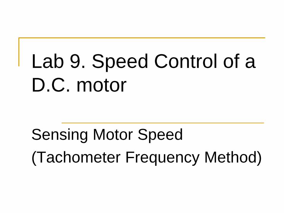
Motor Speed Control Project1. Generate PWM waveform2. Amplify the waveform to drive the motor3. Measure motor speed4. Measure motor parameters5. Control speed with a computer algorithm
microcontroller
12v dcMotor
acTachometer
Amplifier9 v
PowerSupply
ComparatorCircuit
PWM signal
pulses
Frequency Counter
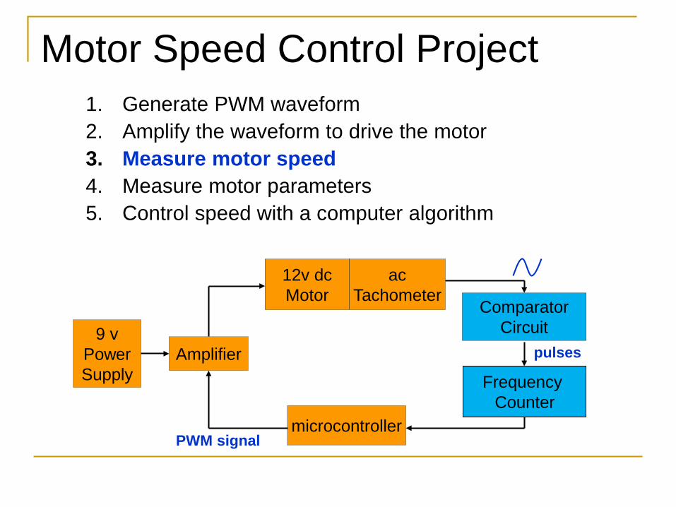
Tachometer circuits
Electrical signal carries speed information (revolutions per unit time) in amplitude and/or frequency Optical encoder: disk on motor shaft alternately
blocks and passes light to a sensor Variable reluctance tachometer: gear teeth pass a
magnetic pickup Pickup coil/generator: voltage induced on
separate winding in the motor
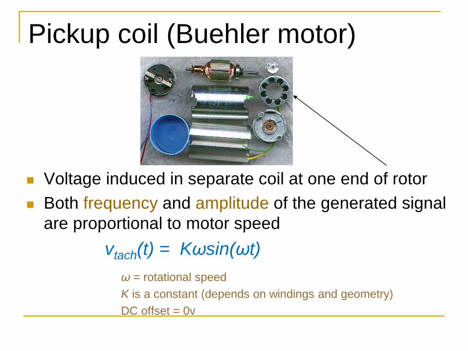
Pickup coil (Buehler motor)
Voltage induced in separate coil at one end of rotor Both frequency and amplitude of the generated signal
are proportional to motor speedvtach(t) = Kωsin(ωt)
ω = rotational speedK is a constant (depends on windings and geometry)DC offset = 0v
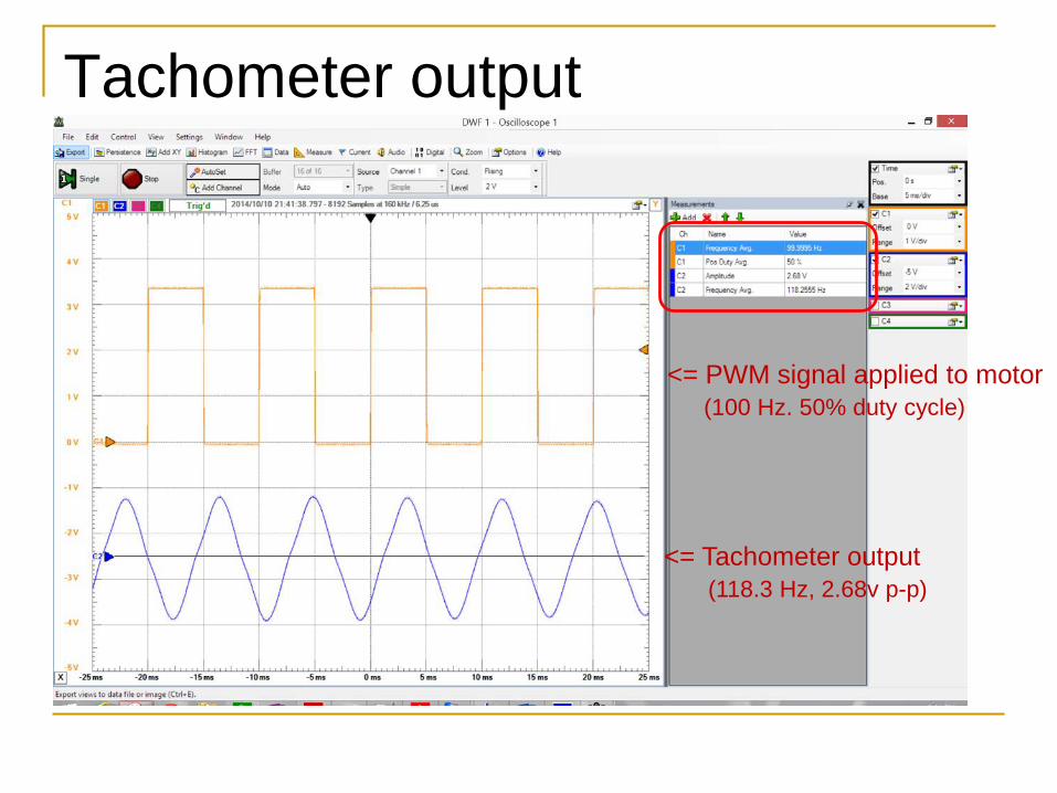
Tachometer output
<= PWM signal applied to motor(100 Hz. 50% duty cycle)
<= Tachometer output(118.3 Hz, 2.68v p-p)
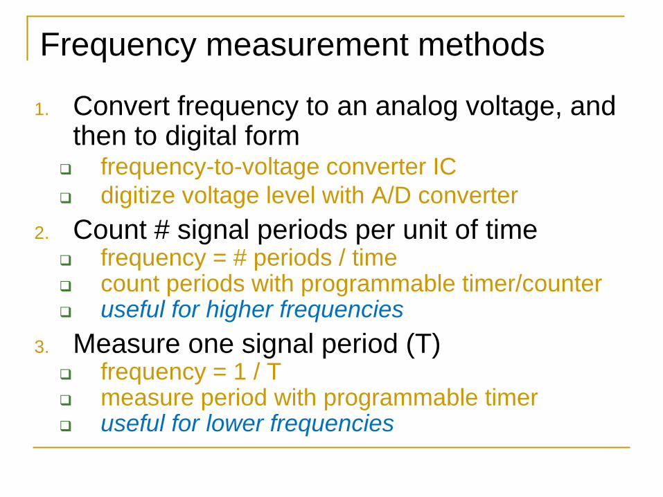
Frequency measurement methods
1. Convert frequency to an analog voltage, and then to digital form
frequency-to-voltage converter IC digitize voltage level with A/D converter
2. Count # signal periods per unit of time frequency = # periods / time count periods with programmable timer/counter useful for higher frequencies
3. Measure one signal period (T) frequency = 1 / T measure period with programmable timer useful for lower frequencies
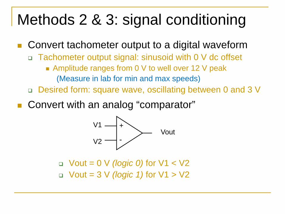
Convert tachometer output to a digital waveform Tachometer output signal: sinusoid with 0 V dc offset
Amplitude ranges from 0 V to well over 12 V peak(Measure in lab for min and max speeds)
Desired form: square wave, oscillating between 0 and 3 V
Convert with an analog “comparator”
Vout = 0 V (logic 0) for V1 < V2 Vout = 3 V (logic 1) for V1 > V2
Methods 2 & 3: signal conditioning
VoutV1
V2
+
-
LM111/LM211/LM311 voltage comparator
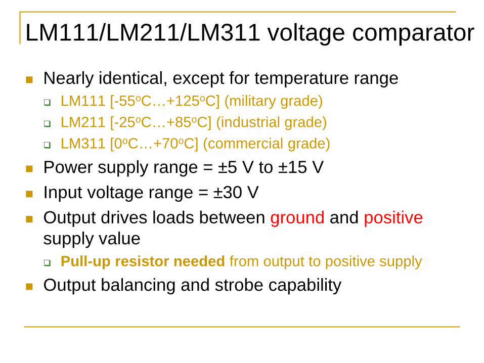
Nearly identical, except for temperature range LM111 [-55oC…+125oC] (military grade) LM211 [-25oC…+85oC] (industrial grade) LM311 [0oC…+70oC] (commercial grade)
Power supply range = ±5 V to ±15 V Input voltage range = ±30 V Output drives loads between ground and positive
supply value Pull-up resistor needed from output to positive supply
Output balancing and strobe capability
LM111 / LM211 / LM311 Package
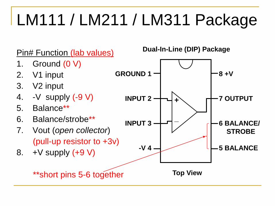
Pin# Function (lab values)1. Ground (0 V)2. V1 input3. V2 input4. -V supply (-9 V)5. Balance**6. Balance/strobe**7. Vout (open collector)
(pull-up resistor to +3v)8. +V supply (+9 V)
**short pins 5-6 together
GROUND 1
INPUT 2
INPUT 3
-V 4
8 +V
7 OUTPUT
6 BALANCE/STROBE
5 BALANCE
Dual-In-Line (DIP) Package
Top View
+
_
Comparator signal & reference voltages(V1 and V2)
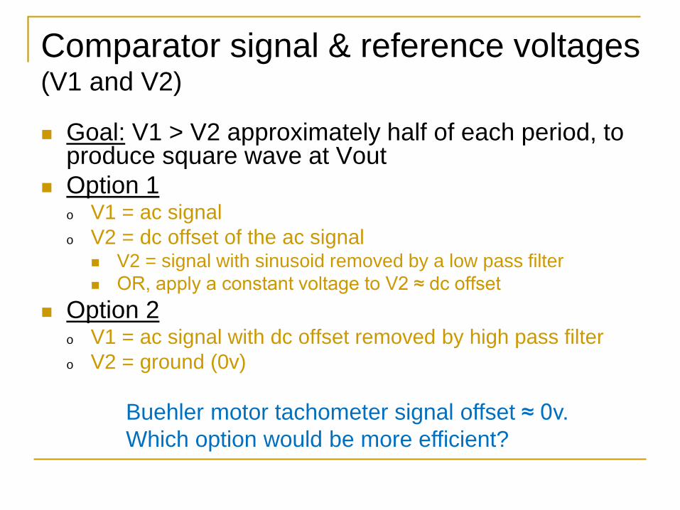
Goal: V1 > V2 approximately half of each period, to produce square wave at Vout
Option 1o V1 = ac signalo V2 = dc offset of the ac signal
V2 = signal with sinusoid removed by a low pass filter OR, apply a constant voltage to V2 ≈ dc offset
Option 2o V1 = ac signal with dc offset removed by high pass filtero V2 = ground (0v)
Buehler motor tachometer signal offset ≈ 0v.Which option would be more efficient?
Design & verify comparator circuit
Model in PSPICE or Multisim LM311 comparator (or LM211 or LM111), resistors,
DC voltages, etc. found in libraries Use a VSTIM (voltage stimulus) generator to model
the optical encoder Simulate to verify square wave output over the
range of optical encoder signal frequencies and amplitudes, corresponding to “useful” motor speeds Use voltage probes to examine signals Measure expected frequencies in lab for min/max speeds
Implement circuit and compare actual operation to simulation of the modeled circuit
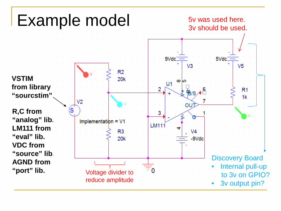
Example model
VSTIMfrom library“sourcstim”
R,C from“analog” lib.LM111 from“eval” lib.VDC from“source” lib.AGND from“port” lib.
5v was used here.3v should be used.
Voltage divider toreduce amplitude
Discovery Board• Internal pull-up
to 3v on GPIO?• 3v output pin?
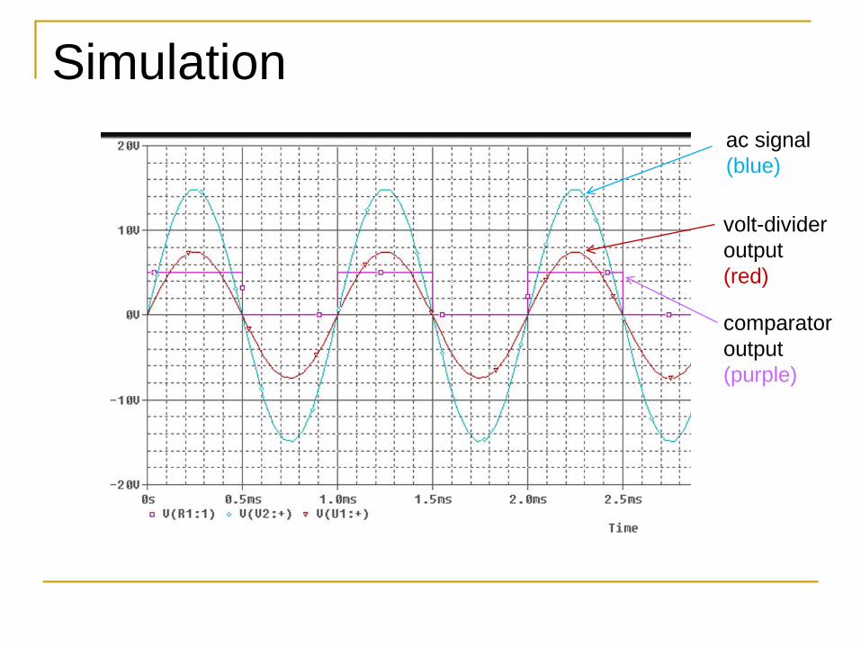
Simulationac signal (blue)
volt-divideroutput(red)
comparatoroutput (purple)
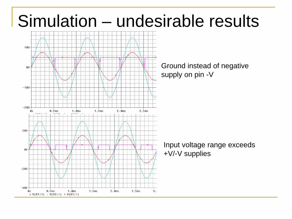
Simulation – undesirable results
Ground instead of negative supply on pin -V
Input voltage range exceeds +V/-V supplies
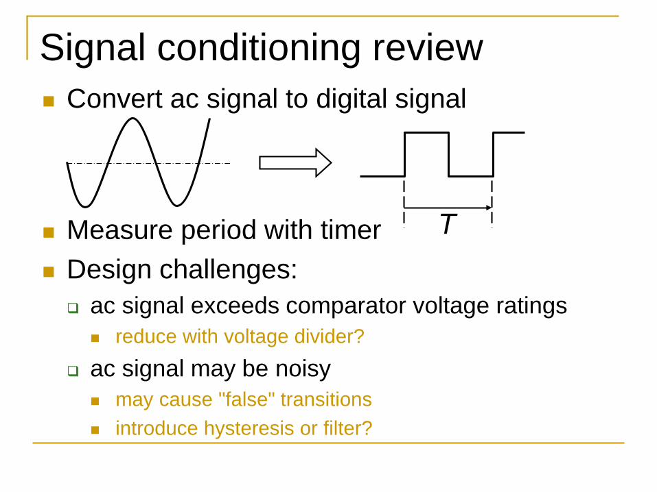
Signal conditioning review Convert ac signal to digital signal
Measure period with timer Design challenges: ac signal exceeds comparator voltage ratings
reduce with voltage divider? ac signal may be noisy
may cause "false" transitions introduce hysteresis or filter?
T
STM32 timer “input capture” mode
16
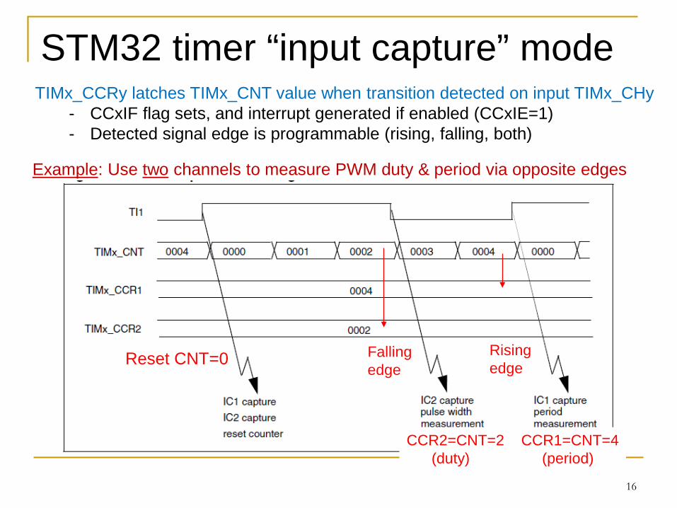
TIMx_CCRy latches TIMx_CNT value when transition detected on input TIMx_CHy- CCxIF flag sets, and interrupt generated if enabled (CCxIE=1)- Detected signal edge is programmable (rising, falling, both)
Example: Use two channels to measure PWM duty & period via opposite edges
Reset CNT=0
CCR2=CNT=2 CCR1=CNT=4(duty) (period)
Falling edge
Rising edge
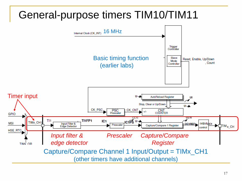
General-purpose timers TIM10/TIM11
17
16 MHz
Capture/Compare Channel 1 Input/Output = TIMx_CH1(other timers have additional channels)
Basic timing function(earlier labs)
Timer input
Input filter & Prescaler Capture/Compareedge detector Register
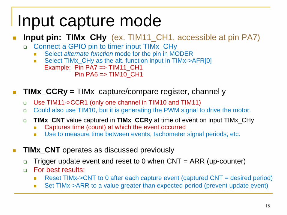
Input capture mode Input pin: TIMx_CHy (ex. TIM11_CH1, accessible at pin PA7)
Connect a GPIO pin to timer input TIMx_CHy Select alternate function mode for the pin in MODER Select TIMx_CHy as the alt. function input in TIMx->AFR[0]
Example: Pin PA7 => TIM11_CH1 Pin PA6 => TIM10_CH1
TIMx_CCRy = TIMx capture/compare register, channel y Use TIM11->CCR1 (only one channel in TIM10 and TIM11) Could also use TIM10, but it is generating the PWM signal to drive the motor. TIMx_CNT value captured in TIMx_CCRy at time of event on input TIMx_CHy
Captures time (count) at which the event occurred Use to measure time between events, tachometer signal periods, etc.
TIMx_CNT operates as discussed previously Trigger update event and reset to 0 when CNT = ARR (up-counter) For best results:
Reset TIMx->CNT to 0 after each capture event (captured CNT = desired period) Set TIMx->ARR to a value greater than expected period (prevent update event)
18
Configure the GPIO alternate function
Refer to User Manual to determine which GPIO pin is able to connect to TIMx_CHy
Example: TIM11_CH1 connects to PA7 In MODER, configure the GPIO pin as AF mode In the GPIO AF register, select TIMx_Chy Configure GPIO PUPDR register if pull-up or pull-down
desired** This should match the edge detection setting (rise or fall) For example, use pull-up if detecting rising edge
** Recall that the LM311 comparator requires a pull-up resistor between its output and +3 V.
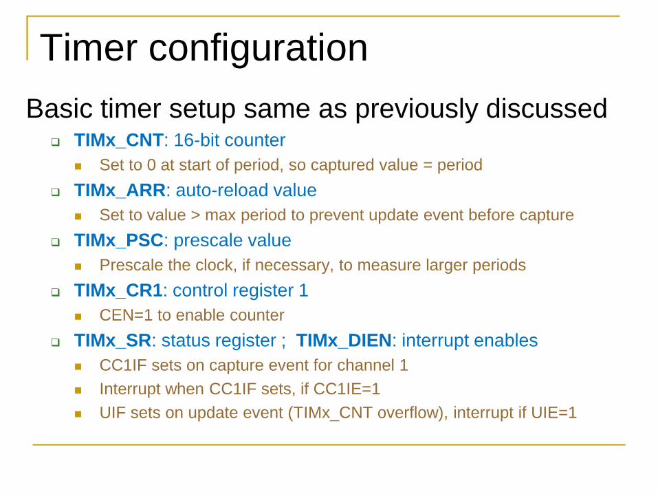
Timer configurationBasic timer setup same as previously discussed
TIMx_CNT: 16-bit counter Set to 0 at start of period, so captured value = period
TIMx_ARR: auto-reload value Set to value > max period to prevent update event before capture
TIMx_PSC: prescale value Prescale the clock, if necessary, to measure larger periods
TIMx_CR1: control register 1 CEN=1 to enable counter
TIMx_SR: status register ; TIMx_DIEN: interrupt enables CC1IF sets on capture event for channel 1 Interrupt when CC1IF sets, if CC1IE=1 UIF sets on update event (TIMx_CNT overflow), interrupt if UIE=1
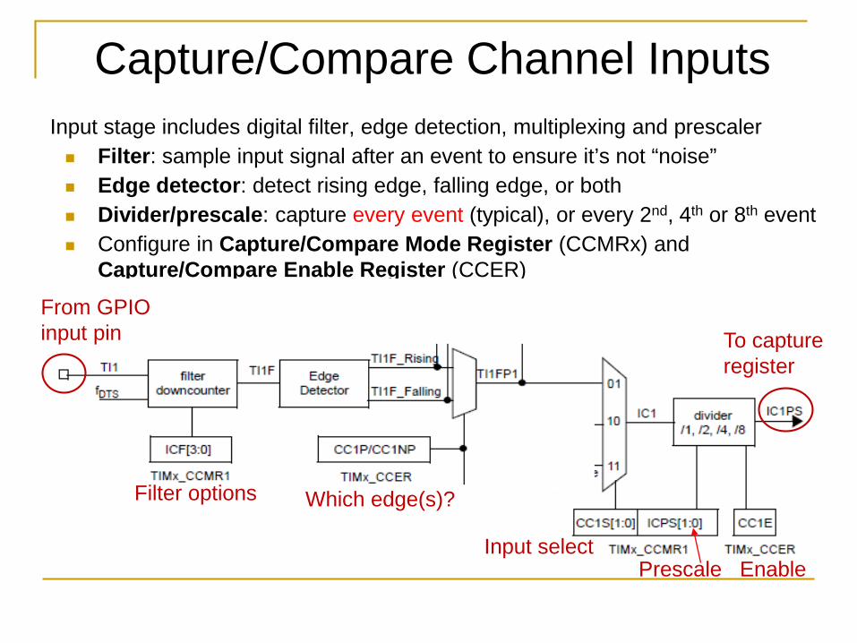
Capture/Compare Channel InputsInput stage includes digital filter, edge detection, multiplexing and prescaler Filter: sample input signal after an event to ensure it’s not “noise” Edge detector: detect rising edge, falling edge, or both Divider/prescale: capture every event (typical), or every 2nd, 4th or 8th event Configure in Capture/Compare Mode Register (CCMRx) and
Capture/Compare Enable Register (CCER)
From GPIOinput pin To capture
register
Which edge(s)?Filter options
Input selectPrescale Enable
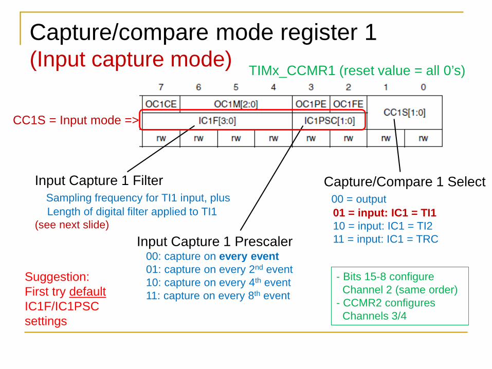
Capture/compare mode register 1 (Input capture mode)
Capture/Compare 1 Select00 = output01 = input: IC1 = TI110 = input: IC1 = TI211 = input: IC1 = TRC
Input Capture 1 FilterSampling frequency for TI1 input, plus Length of digital filter applied to TI1
(see next slide)Input Capture 1 Prescaler
00: capture on every event01: capture on every 2nd event10: capture on every 4th event11: capture on every 8th event
CC1S = Input mode =>
- Bits 15-8 configureChannel 2 (same order)
- CCMR2 configuresChannels 3/4
TIMx_CCMR1 (reset value = all 0’s)
Suggestion:First try defaultIC1F/IC1PSCsettings
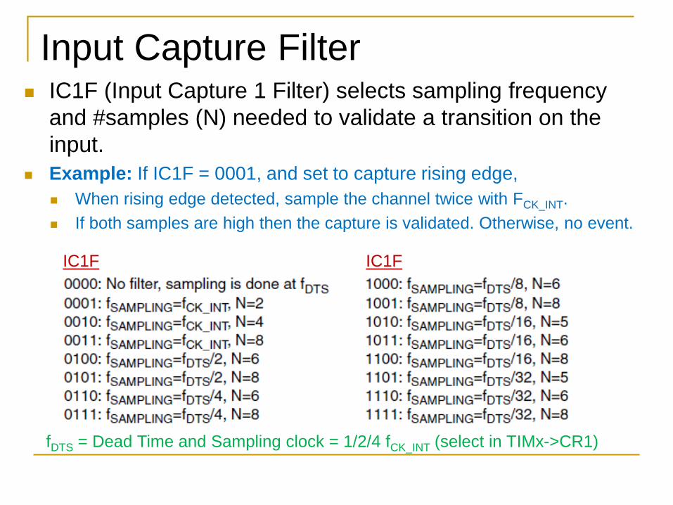
Input Capture Filter IC1F (Input Capture 1 Filter) selects sampling frequency
and #samples (N) needed to validate a transition on the input.
Example: If IC1F = 0001, and set to capture rising edge, When rising edge detected, sample the channel twice with FCK_INT. If both samples are high then the capture is validated. Otherwise, no event.
IC1F IC1F
fDTS = Dead Time and Sampling clock = 1/2/4 fCK_INT (select in TIMx->CR1)
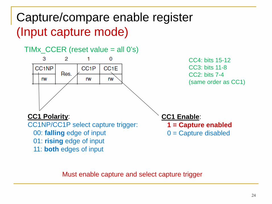
Capture/compare enable register(Input capture mode)
24
TIMx_CCER (reset value = all 0’s)CC4: bits 15-12CC3: bits 11-8CC2: bits 7-4(same order as CC1)
CC1 Polarity:CC1NP/CC1P select capture trigger:
00: falling edge of input01: rising edge of input11: both edges of input
CC1 Enable:1 = Capture enabled0 = Capture disabled
Must enable capture and select capture trigger
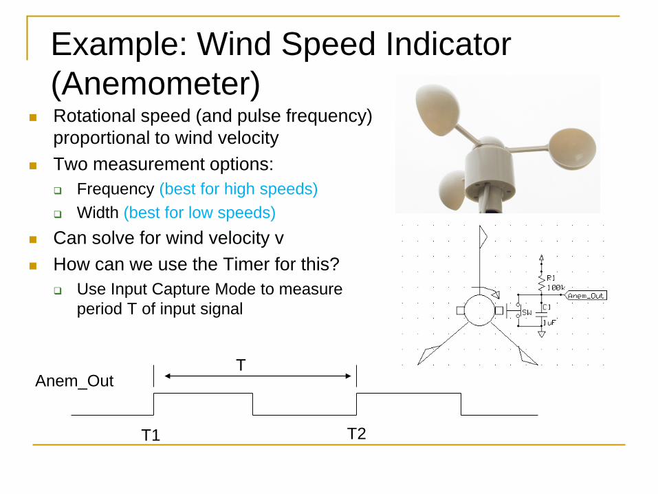
Example: Wind Speed Indicator (Anemometer)
Rotational speed (and pulse frequency) proportional to wind velocity
Two measurement options: Frequency (best for high speeds) Width (best for low speeds)
Can solve for wind velocity v How can we use the Timer for this?
Use Input Capture Mode to measure period T of input signal
T1 T2
TAnem_Out
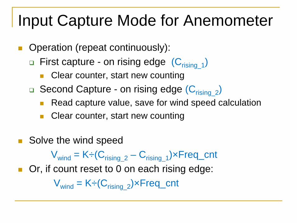
Input Capture Mode for Anemometer Operation (repeat continuously):
First capture - on rising edge (Crising_1) Clear counter, start new counting
Second Capture - on rising edge (Crising_2) Read capture value, save for wind speed calculation Clear counter, start new counting
Solve the wind speedVwind = K÷(Crising_2 – Crising_1)×Freq_cnt
Or, if count reset to 0 on each rising edge: Vwind = K÷(Crising_2)×Freq_cnt
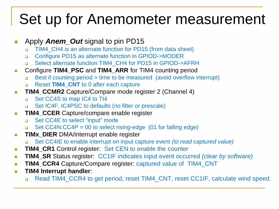
Set up for Anemometer measurement Apply Anem_Out signal to pin PD15
TIM4_CH4 is an alternate function for PD15 (from data sheet) Configure PD15 as alternate function in GPIOD->MODER Select alternate function TIM4_CH4 for PD15 in GPIOD->AFRH
Configure TIM4_PSC and TIM4_ARR for TIM4 counting period Best if counting period > time to be measured (avoid overflow interrupt) Reset TIM4_CNT to 0 after each capture
TIM4_CCMR2 Capture/Compare mode register 2 (Channel 4) Set CC4S to map IC4 to TI4 Set IC4F, IC4PSC to defaults (no filter or prescale)
TIM4_CCER Capture/compare enable register Set CC4E to select “input” mode Set CC4N:CC4P = 00 to select rising-edge (01 for falling edge)
TIMx_DIER DMA/interrupt enable register Set CC4IE to enable interrupt on input capture event (to read captured value)
TIM4_CR1 Control register: Set CEN to enable the counter TIM4_SR Status register: CC1IF indicates input event occurred (clear by software) TIM4_CCR4 Capture/Compare register: captured value of TIM4_CNT TIM4 Interrupt handler:
Read TIM4_CCR4 to get period, reset TIM4_CNT, reset CC1IF, calculate wind speed.
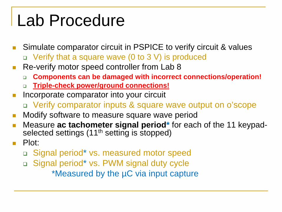
Lab Procedure Simulate comparator circuit in PSPICE to verify circuit & values
Verify that a square wave (0 to 3 V) is produced Re-verify motor speed controller from Lab 8
Components can be damaged with incorrect connections/operation! Triple-check power/ground connections!
Incorporate comparator into your circuit Verify comparator inputs & square wave output on o’scope
Modify software to measure square wave period Measure ac tachometer signal period* for each of the 11 keypad-
selected settings (11th setting is stopped) Plot:
Signal period* vs. measured motor speed Signal period* vs. PWM signal duty cycle
*Measured by the µC via input capture