Embed Size (px)
Citation preview

Lab 11. Speed Control of a D.C. motor
Motor Characterization

Motor Speed Control Project
1. Generate PWM waveform2. Amplify the waveform to drive the motor3. Measure motor speed4. Estimate motor parameters from measured data5. Regulate speed with a controller
ComputerSystem
12v DCMotor Tachometer
SpeedMeasurementAmplifier
9vPowerSupply Labs 11/12

Goals of this lab
Experimentally determine the control system model of the motor/hardware setup Measure response to a step input
(determine time constant, gain, etc.)
This model will be used in the design of a speed controller

Motor control system modeled as a feedback system
PWM signal
Tachometer + comparator/counter (period)or envelope detector (amplitude)
Software
Userentry
(systeminput)
(Frequency domain model)

Simplified system modelDuty cycle of PWM signal
periodor amplitude
Switchsetting
Determineexperimentally
The PlantG(S)
ControllerC(S)
+_
Measured SignalY(S)
SetpointR(s)
ErrorE(S)
Computer Software
Motor andElectronicsControl
ActionX(S)

What goes into the plant G(s)?
Amplifier dynamics Electrical dynamics (motor winding has
inductance and resistance) Mechanical dynamics (motor rotor has inertia
and experiences friction) Sensor dynamics (filter has capacitance and
resistance)
OVERALL: A 3rd order model (or higher)
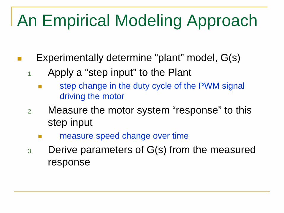
An Empirical Modeling Approach
Experimentally determine “plant” model, G(s)1. Apply a “step input” to the Plant
step change in the duty cycle of the PWM signal driving the motor
2. Measure the motor system “response” to this step input
measure speed change over time
3. Derive parameters of G(s) from the measured response

Response y(t) of a 1st-order system to a step input x(t)
)(ty
t
Motor speed(ADC
reading)
Plant input = change in PWM duty cycle(at t = 0)
)(tx

First-order system model
x(t) = system inputy(t) = system outputK = gainτ = time constant
Solution if step input applied at t=0 (step response):
System equation:
∆x = input changeat time t=0
Laplace transform (plant transfer function):
)()( tydtdytKx += τ
))(()( /τtetxKty −−∆=∆ 1
1+==
sK
sXsYsG
τ)()()(

Experimentally determining G(s) for the first-order system After the transient period (t large), study output y:
At t=τ, step response is:
xyK
xKy
∆∆
=
∆=∆ Experimentally measurechange in y (after large t)to compute gain, K.
)632.0()()1()( /
xKyexKy
∆=−∆= −
ττ ττ Experimentally measure
time at which y(t) = 63.2% of final value to determinetime constant, τ.

Finding gain K
t
y∆
x∆ xyK
∆∆
=
large t

Finding time constant τ
τ t
y∆
t = 0
y∆6320.
x∆
ττ 5 or 4 time settling ≈

Verify model in MATLAB/Simulink
(Controller to be added to this to compute the controller parameters.)

First-order response with delay
)(ty )( tty ∆−
tt∆
x∆

First-order system with delay
tsesKsG ∆−
+=
1τ)(
represents time delay ∆ttse ∆−

Second-order step response
overdamped(real, unequal poles)
underdamped
critically damped

Underdamped 2nd-order model
( )( ) 22
2
2 nn
n
ssK
sXsYsG
ωζωω
++==)(
dampingfactor undamped natural
frequency
gain

2nd-order model character (a) Underdamped ( 0 < ζ < 1 ) model has
complex conjugate poles:
time constant: inverse of the |Re| part
ImRe
,2
21 1 ζωζω −±−= nn js
τ =1
ζωn

Underdamped step response
t
y∆
x∆xyK
∆∆
=
overshootperiod
frequency
noscillatio dampedπω 2
=d
τ4 time settling ≈

2nd-order model character (b) oscillation frequency (rad/s): Im part
overshoot (% of final value)
a function only of damping factor
ωd = ωn 1−ζ 2
% overshoot = e−
ReIm
π
×100

Other 2nd-order forms Critically damped model has 2 equal poles
Overdamped model has unequal poles
( )( )21+
=s
KsGτ
( ) ( )( )11 21 ++=
ssKsG
ττ
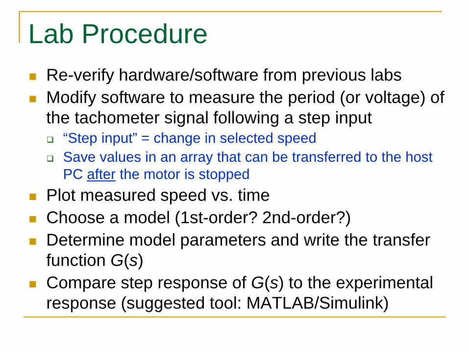
Lab Procedure Re-verify hardware/software from previous labs Modify software to measure the period (or voltage) of
the tachometer signal following a step input “Step input” = change in selected speed Save values in an array that can be transferred to the host
PC after the motor is stopped Plot measured speed vs. time Choose a model (1st-order? 2nd-order?) Determine model parameters and write the transfer
function G(s) Compare step response of G(s) to the experimental
response (suggested tool: MATLAB/Simulink)