Embed Size (px)
Citation preview
CompTIA Network+® Lab Series
Network Concepts
Lab 1: The OSI Model Objective 1.1: Compare the layers of the OSI and TCP/IP models Objective 1.2: Classify how applications, devices and protocols relate to the OSI model
Document Version: 2015-09-18
This work by the National Information Security and Geospatial Technologies Consortium (NISGTC), and except where otherwise noted, is licensed under the Creative Commons Attribution 3.0 Unported License.
Development was funded by the Department of Labor (DOL) Trade Adjustment Assistance Community College and Career Training (TAACCCT) Grant No. TC-22525-11-60-A-48; The National Information Security, Geospatial Technologies Consortium (NISGTC) is an entity of Collin College of Texas, Bellevue College of Washington, Bunker Hill Community College of Massachusetts, Del Mar College of Texas, Moraine Valley Community College of Illinois, Rio Salado College of Arizona, and Salt Lake Community College of Utah.
This workforce solution was funded by a grant awarded by the U.S. Department of Labor's Employment and Training Administration. The solution was created by the grantee and does not necessarily reflect the official position of the U.S. Department of Labor. The Department of Labor makes no guarantees, warranties or assurances of any kind, express or implied, with respect to such information, including any information on linked sites, and including, but not limited to accuracy of the information or its completeness, timeliness, usefulness, adequacy, continued availability or ownership.
Lab 1: The OSI Model
2
This work by the National Information Security and Geospatial Technologies Consortium (NISGTC), and except where otherwise noted, is licensed under the Creative Commons Attribution 3.0 Unported License.
Contents Introduction ........................................................................................................................ 3
Objective: Identify Layers of OSI Model ............................................................................ 3
Lab Topology ....................................................................................................................... 5
Lab Settings ......................................................................................................................... 6
1 Review of the OSI Model and Wireshark .................................................................... 7
2 Reviewing the Application, Presentation and Session Layers .................................. 10
2.1 Data Link Protocol Data Unit .............................................................................. 10
2.2 Conclusion .......................................................................................................... 14
2.3 Review Questions ............................................................................................... 14
3 Reviewing the Transport Layer ................................................................................. 15
3.1 Segment Protocol Data Unit .............................................................................. 15
3.2 Conclusion .......................................................................................................... 23
3.3 Review Questions ............................................................................................... 23
4 Reviewing the Network Layer ................................................................................... 24
4.1 The Packet Protocol Data Unit ........................................................................... 24
4.2 Conclusion .......................................................................................................... 27
4.3 Review Questions ............................................................................................... 27
5 Reviewing the Data Link Layer .................................................................................. 28
5.1 Frame Protocol Data Unit................................................................................... 28
5.2 Conclusion .......................................................................................................... 31
5.3 Review Questions ............................................................................................... 31
6 Reviewing the Physical Layer .................................................................................... 32
6.1 Bit Protocol Data Unit ........................................................................................ 32
6.2 Conclusion .......................................................................................................... 34
6.3 Review Questions ............................................................................................... 34
Lab 1: The OSI Model
3
This work by the National Information Security and Geospatial Technologies Consortium (NISGTC), and except where otherwise noted, is licensed under the Creative Commons Attribution 3.0 Unported License.
Introduction
This lab is part of a series of lab exercises designed to supplement coursework and provide students with a hands-on training experience based on real world applications. This series of lab exercises is intended to support courseware for CompTIA Network+® certification. This lab will utilize Wireshark® to review network traffic. Wireshark is a network protocol analyzer licensed under GNU General Public License. A network protocol analyzer is used to capture data packets on a network. Students will review several layers of the OSI model during this lab. Students will be able to describe the encapsulation process and the function of specific protocols that operate within particular layers of the OSI model. This lab includes the following tasks:
1. Reviewing the Application, Presentation and Session layers 2. Reviewing the Transport layer 3. Reviewing the Network layer 4. Reviewing the Data Link layer 5. Reviewing the Physical layer
Objective: Identify Layers of OSI Model
The OSI model provides the basic framework for understanding how traffic moves through a network. Different functions pertain to specific layers of the OSI model. This lab will identify the layers of the OSI model, various protocols that operate at each layer, and the role that each layer has in transmitting data packets between any two endpoints in a telecommunication network Key terms for this lab: OSI – Open System Interconnect, developed by the International Standards Organization (ISO) PDU – Protocol Data Unit, a term used to describe the product of encapsulation at a given layer of the OSI model Connection-oriented data transfer – a transfer of data that requires the establishment of a connection between communicating endpoints, before the transfer can begin Connectionless data transfer – a transfer of data that is serviced without requiring a verified session and without guaranteeing delivery of data
Lab 1: The OSI Model
4
This work by the National Information Security and Geospatial Technologies Consortium (NISGTC), and except where otherwise noted, is licensed under the Creative Commons Attribution 3.0 Unported License.
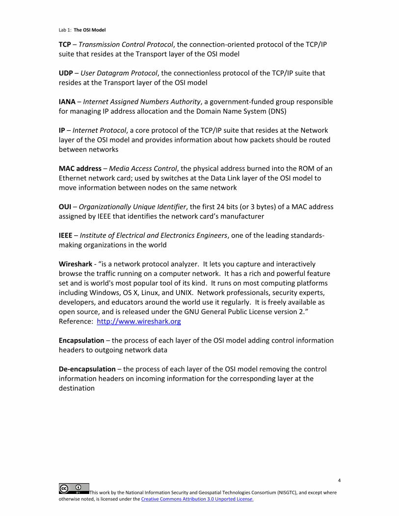
TCP – Transmission Control Protocol, the connection-oriented protocol of the TCP/IP suite that resides at the Transport layer of the OSI model UDP – User Datagram Protocol, the connectionless protocol of the TCP/IP suite that resides at the Transport layer of the OSI model IANA – Internet Assigned Numbers Authority, a government-funded group responsible for managing IP address allocation and the Domain Name System (DNS) IP – Internet Protocol, a core protocol of the TCP/IP suite that resides at the Network layer of the OSI model and provides information about how packets should be routed between networks MAC address – Media Access Control, the physical address burned into the ROM of an Ethernet network card; used by switches at the Data Link layer of the OSI model to move information between nodes on the same network OUI – Organizationally Unique Identifier, the first 24 bits (or 3 bytes) of a MAC address assigned by IEEE that identifies the network card’s manufacturer IEEE – Institute of Electrical and Electronics Engineers, one of the leading standards-making organizations in the world Wireshark - “is a network protocol analyzer. It lets you capture and interactively browse the traffic running on a computer network. It has a rich and powerful feature set and is world's most popular tool of its kind. It runs on most computing platforms including Windows, OS X, Linux, and UNIX. Network professionals, security experts, developers, and educators around the world use it regularly. It is freely available as open source, and is released under the GNU General Public License version 2.” Reference: http://www.wireshark.org Encapsulation – the process of each layer of the OSI model adding control information headers to outgoing network data De-encapsulation – the process of each layer of the OSI model removing the control information headers on incoming information for the corresponding layer at the destination
Lab 1: The OSI Model
5
This work by the National Information Security and Geospatial Technologies Consortium (NISGTC), and except where otherwise noted, is licensed under the Creative Commons Attribution 3.0 Unported License.
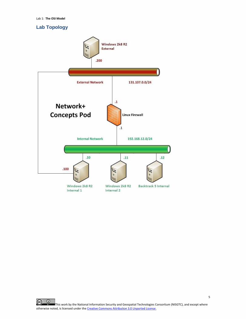
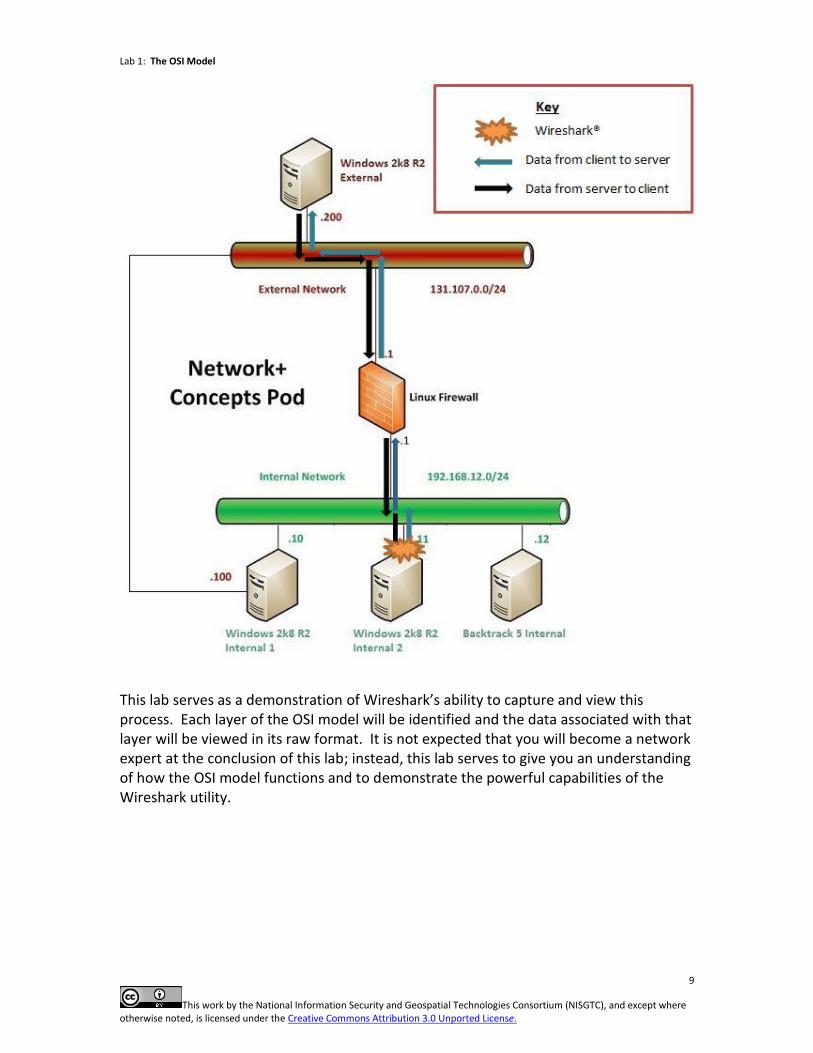
Lab Topology
Lab 1: The OSI Model
6
This work by the National Information Security and Geospatial Technologies Consortium (NISGTC), and except where otherwise noted, is licensed under the Creative Commons Attribution 3.0 Unported License.
Lab Settings
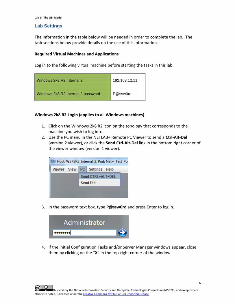
The information in the table below will be needed in order to complete the lab. The task sections below provide details on the use of this information. Required Virtual Machines and Applications Log in to the following virtual machine before starting the tasks in this lab: Windows 2k8 R2 Internal 2
192.168.12.11
Windows 2k8 R2 Internal 2 password
P@ssw0rd
Windows 2k8 R2 Login (applies to all Windows machines)
1. Click on the Windows 2k8 R2 icon on the topology that corresponds to the machine you wish to log into.
2. Use the PC menu in the NETLAB+ Remote PC Viewer to send a Ctrl-Alt-Del (version 2 viewer), or click the Send Ctrl-Alt-Del link in the bottom right corner of the viewer window (version 1 viewer).
3. In the password text box, type P@ssw0rd and press Enter to log in.
4. If the Initial Configuration Tasks and/or Server Manager windows appear, close them by clicking on the “X” in the top-right corner of the window
Lab 1: The OSI Model
7
This work by the National Information Security and Geospatial Technologies Consortium (NISGTC), and except where otherwise noted, is licensed under the Creative Commons Attribution 3.0 Unported License.
1 Review of the OSI Model and Wireshark
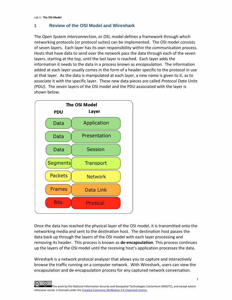
The Open System Interconnection, or OSI, model defines a framework through which networking protocols (or protocol suites) can be implemented. The OSI model consists of seven layers. Each layer has its own responsibility within the communication process. Hosts that have data to send over the network pass the data through each of the seven layers, starting at the top, until the last layer is reached. Each layer adds the information it needs to the data in a process known as encapsulation. The information added at each layer usually comes in the form of a header specific to the protocol in use at that layer. As the data is manipulated at each layer, a new name is given to it, as to associate it with the specific layer. These new data pieces are called Protocol Data Units (PDU). The seven layers of the OSI model and the PDU associated with the layer is shown below.
Once the data has reached the physical layer of the OSI model, it is transmitted onto the networking media and sent to the destination host. The destination host passes the data back up through the layers of the OSI model with each layer processing and removing its header. This process is known as de-encapsulation. This process continues up the layers of the OSI model until the receiving host’s application processes the data. Wireshark is a network protocol analyzer that allows you to capture and interactively browse the traffic running on a computer network. With Wireshark, users can view the encapsulation and de-encapsulation process for any captured network conversation.
Lab 1: The OSI Model
8
This work by the National Information Security and Geospatial Technologies Consortium (NISGTC), and except where otherwise noted, is licensed under the Creative Commons Attribution 3.0 Unported License.
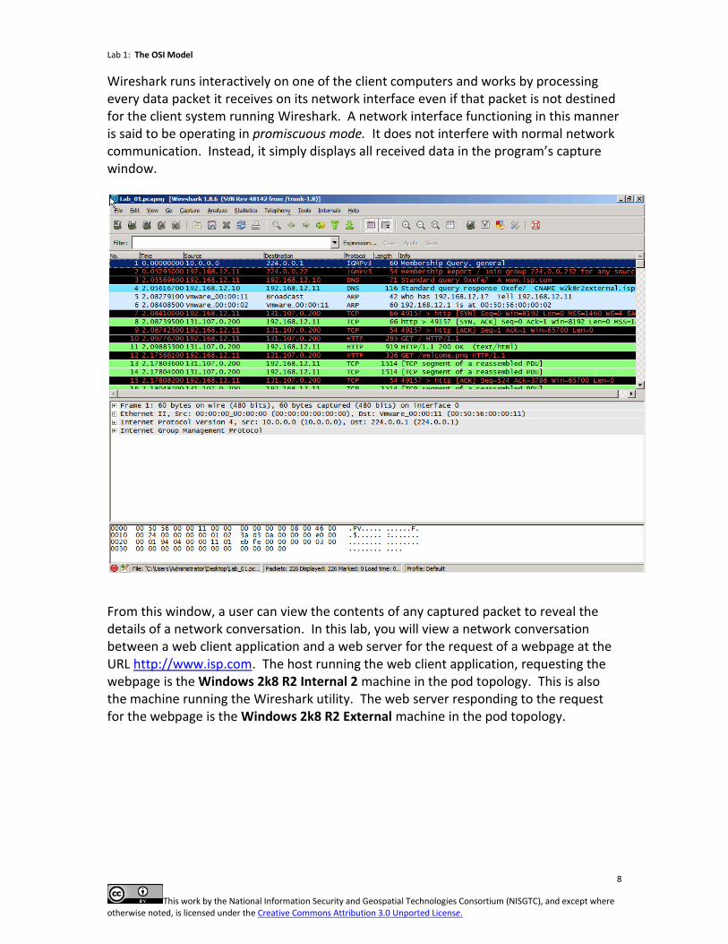
Wireshark runs interactively on one of the client computers and works by processing every data packet it receives on its network interface even if that packet is not destined for the client system running Wireshark. A network interface functioning in this manner is said to be operating in promiscuous mode. It does not interfere with normal network communication. Instead, it simply displays all received data in the program’s capture window.
From this window, a user can view the contents of any captured packet to reveal the details of a network conversation. In this lab, you will view a network conversation between a web client application and a web server for the request of a webpage at the URL http://www.isp.com. The host running the web client application, requesting the webpage is the Windows 2k8 R2 Internal 2 machine in the pod topology. This is also the machine running the Wireshark utility. The web server responding to the request for the webpage is the Windows 2k8 R2 External machine in the pod topology.
Lab 1: The OSI Model
9
This work by the National Information Security and Geospatial Technologies Consortium (NISGTC), and except where otherwise noted, is licensed under the Creative Commons Attribution 3.0 Unported License.
This lab serves as a demonstration of Wireshark’s ability to capture and view this process. Each layer of the OSI model will be identified and the data associated with that layer will be viewed in its raw format. It is not expected that you will become a network expert at the conclusion of this lab; instead, this lab serves to give you an understanding of how the OSI model functions and to demonstrate the powerful capabilities of the Wireshark utility.
Lab 1: The OSI Model
10
This work by the National Information Security and Geospatial Technologies Consortium (NISGTC), and except where otherwise noted, is licensed under the Creative Commons Attribution 3.0 Unported License.
2 Reviewing the Application, Presentation and Session Layers
Many protocols operate at the application, presentation, and session layers of the OSI model. The top three layers of the OSI are often looked at from the perspective of the TCP/IP model, which encompasses all three layers into one layer labeled application. These three layers operate on the data that is being formed and readied to be packaged. The PDU associated with information created by any of the top three layers of the OSI model is referred to as data. The protocols at these layers prepare the data by formatting it based on the network service or application being used, encrypting and encoding the data, and controlling the dialog between the end system applications. Examples of network services, protocols, and client requests interfacing at these layers include File Transfer Protocol (FTP), Telnet and Hypertext Transfer Protocol (HTTP). 2.1 Data Link Protocol Data Unit
1. Use the instructions provided in the Lab Settings section to log onto the
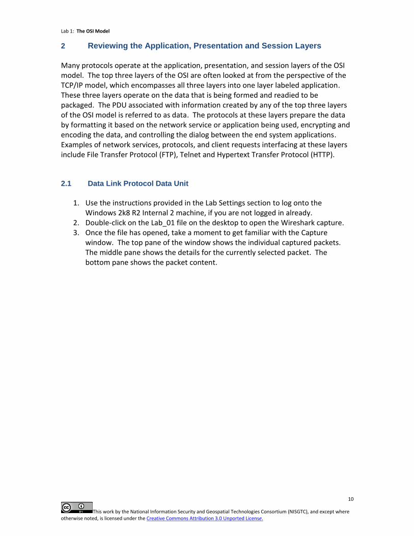
Windows 2k8 R2 Internal 2 machine, if you are not logged in already. 2. Double-click on the Lab_01 file on the desktop to open the Wireshark capture. 3. Once the file has opened, take a moment to get familiar with the Capture
window. The top pane of the window shows the individual captured packets. The middle pane shows the details for the currently selected packet. The bottom pane shows the packet content.
Lab 1: The OSI Model
11
This work by the National Information Security and Geospatial Technologies Consortium (NISGTC), and except where otherwise noted, is licensed under the Creative Commons Attribution 3.0 Unported License.
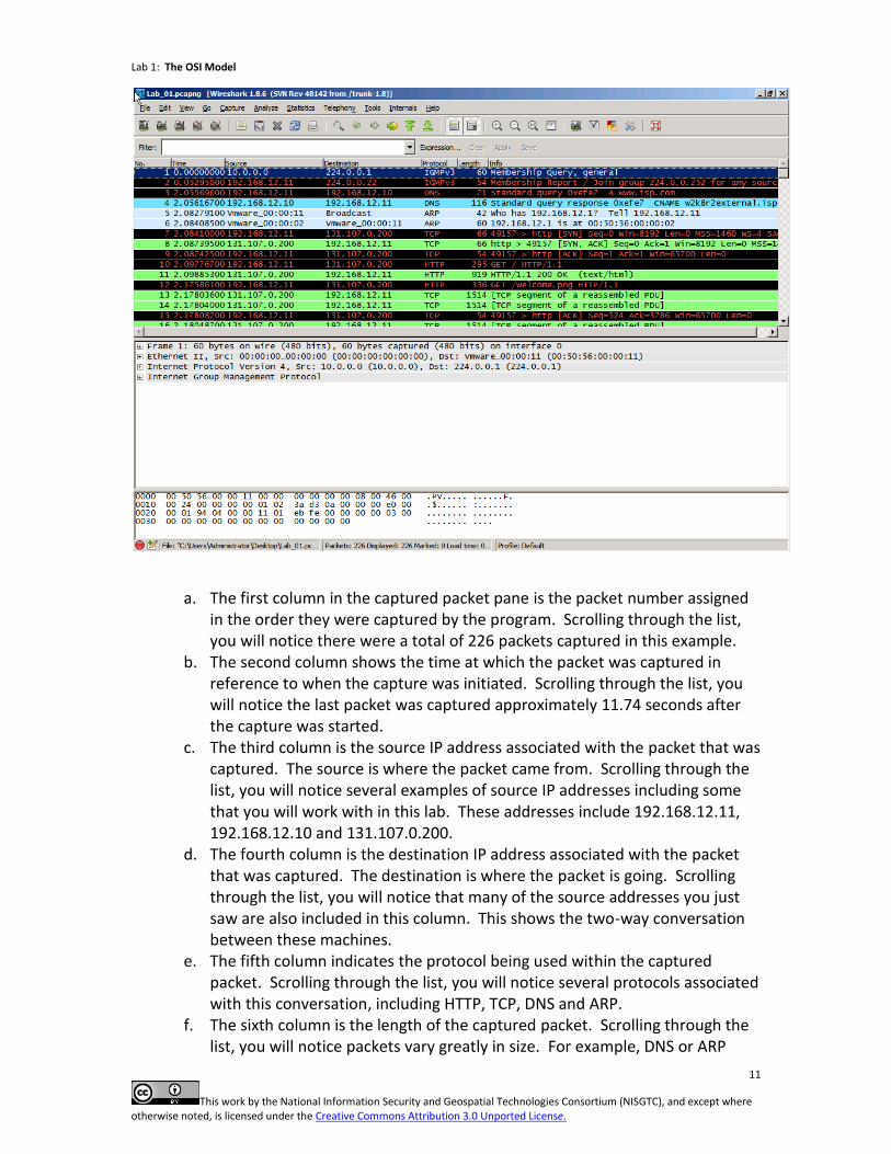
a. The first column in the captured packet pane is the packet number assigned in the order they were captured by the program. Scrolling through the list, you will notice there were a total of 226 packets captured in this example.
b. The second column shows the time at which the packet was captured in reference to when the capture was initiated. Scrolling through the list, you will notice the last packet was captured approximately 11.74 seconds after the capture was started.
c. The third column is the source IP address associated with the packet that was captured. The source is where the packet came from. Scrolling through the list, you will notice several examples of source IP addresses including some that you will work with in this lab. These addresses include 192.168.12.11, 192.168.12.10 and 131.107.0.200.
d. The fourth column is the destination IP address associated with the packet that was captured. The destination is where the packet is going. Scrolling through the list, you will notice that many of the source addresses you just saw are also included in this column. This shows the two-way conversation between these machines.
e. The fifth column indicates the protocol being used within the captured packet. Scrolling through the list, you will notice several protocols associated with this conversation, including HTTP, TCP, DNS and ARP.
f. The sixth column is the length of the captured packet. Scrolling through the list, you will notice packets vary greatly in size. For example, DNS or ARP
Lab 1: The OSI Model
12
This work by the National Information Security and Geospatial Technologies Consortium (NISGTC), and except where otherwise noted, is licensed under the Creative Commons Attribution 3.0 Unported License.
packets are relatively small while several of the TCP packets are relatively large.
g. The seventh and final column gives you information about what is inside of the packet. Scrolling through the list, the information within packets will vary greatly.
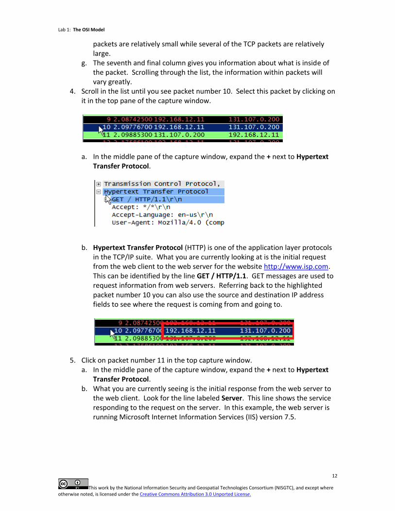
4. Scroll in the list until you see packet number 10. Select this packet by clicking on it in the top pane of the capture window.
a. In the middle pane of the capture window, expand the + next to Hypertext
Transfer Protocol.
b. Hypertext Transfer Protocol (HTTP) is one of the application layer protocols in the TCP/IP suite. What you are currently looking at is the initial request from the web client to the web server for the website http://www.isp.com. This can be identified by the line GET / HTTP/1.1. GET messages are used to request information from web servers. Referring back to the highlighted packet number 10 you can also use the source and destination IP address fields to see where the request is coming from and going to.
5. Click on packet number 11 in the top capture window. a. In the middle pane of the capture window, expand the + next to Hypertext
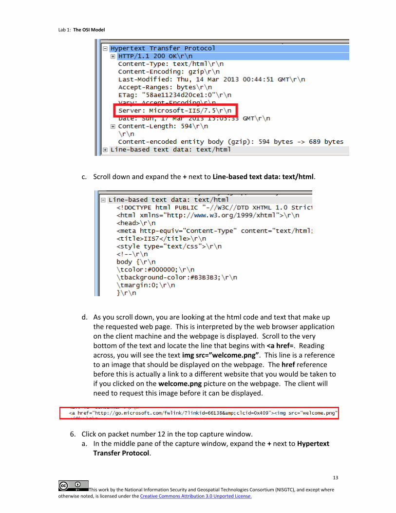
Transfer Protocol. b. What you are currently seeing is the initial response from the web server to
the web client. Look for the line labeled Server. This line shows the service responding to the request on the server. In this example, the web server is running Microsoft Internet Information Services (IIS) version 7.5.
Lab 1: The OSI Model
13
This work by the National Information Security and Geospatial Technologies Consortium (NISGTC), and except where otherwise noted, is licensed under the Creative Commons Attribution 3.0 Unported License.
c. Scroll down and expand the + next to Line-based text data: text/html.
d. As you scroll down, you are looking at the html code and text that make up the requested web page. This is interpreted by the web browser application on the client machine and the webpage is displayed. Scroll to the very bottom of the text and locate the line that begins with <a href=. Reading across, you will see the text img src=”welcome.png”. This line is a reference to an image that should be displayed on the webpage. The href reference before this is actually a link to a different website that you would be taken to if you clicked on the welcome.png picture on the webpage. The client will need to request this image before it can be displayed.
6. Click on packet number 12 in the top capture window. a. In the middle pane of the capture window, expand the + next to Hypertext
Transfer Protocol.
Lab 1: The OSI Model
14
This work by the National Information Security and Geospatial Technologies Consortium (NISGTC), and except where otherwise noted, is licensed under the Creative Commons Attribution 3.0 Unported License.
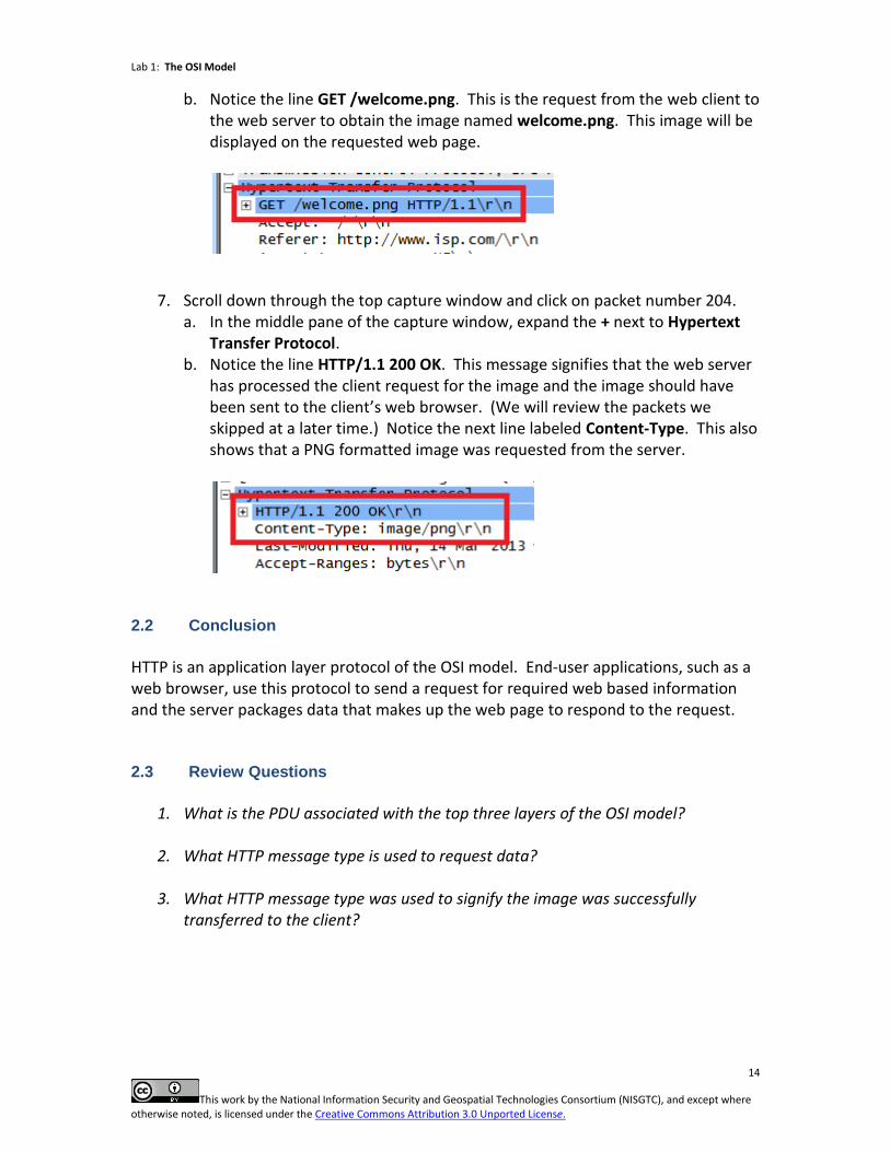
b. Notice the line GET /welcome.png. This is the request from the web client to the web server to obtain the image named welcome.png. This image will be displayed on the requested web page.
7. Scroll down through the top capture window and click on packet number 204. a. In the middle pane of the capture window, expand the + next to Hypertext
Transfer Protocol. b. Notice the line HTTP/1.1 200 OK. This message signifies that the web server
has processed the client request for the image and the image should have been sent to the client’s web browser. (We will review the packets we skipped at a later time.) Notice the next line labeled Content-Type. This also shows that a PNG formatted image was requested from the server.
2.2 Conclusion
HTTP is an application layer protocol of the OSI model. End-user applications, such as a web browser, use this protocol to send a request for required web based information and the server packages data that makes up the web page to respond to the request. 2.3 Review Questions
1. What is the PDU associated with the top three layers of the OSI model?
2. What HTTP message type is used to request data?
3. What HTTP message type was used to signify the image was successfully
transferred to the client?
Lab 1: The OSI Model
15
This work by the National Information Security and Geospatial Technologies Consortium (NISGTC), and except where otherwise noted, is licensed under the Creative Commons Attribution 3.0 Unported License.
3 Reviewing the Transport Layer
The OSI model has multiple protocols at the transport layer. In the TCP/IP model there are two protocols that reside at the transport layer, TCP and UDP. TCP and UDP are the most widely referenced transport protocols in the OSI and most of the TCP and UDP functions map to the OSI transport layer. TCP and UDP use port numbers to differentiate between application transmissions. IANA uses RFC 6335 to describe the procedures for assigning port numbers. The TCP protocol is responsible for connection-oriented data transmission. TCP conversations always start with a three-way handshake. This process prepares both the server providing the information and the client receiving the information for the communication. TCP also uses acknowledgments to verify data transmission. The UDP protocol is responsible for connectionless data transmission. UDP only sends data – it does not send acknowledgments to verify data transmission. This layer is also responsible for breaking down large data into smaller, more manageable pieces. This process for TCP is known as segmentation. With UDP the more manageable pieces are called datagrams and have no sequencing information included. The PDU associated with the transport layer of the OSI model is a segment for TCP and datagram for UDP. 3.1 Segment Protocol Data Unit
1. On the Windows 2k8 R2 Internal 2 machine, scroll up through the top capture
window until you see frame number 7. Select this frame by clicking on it in the top capture window.
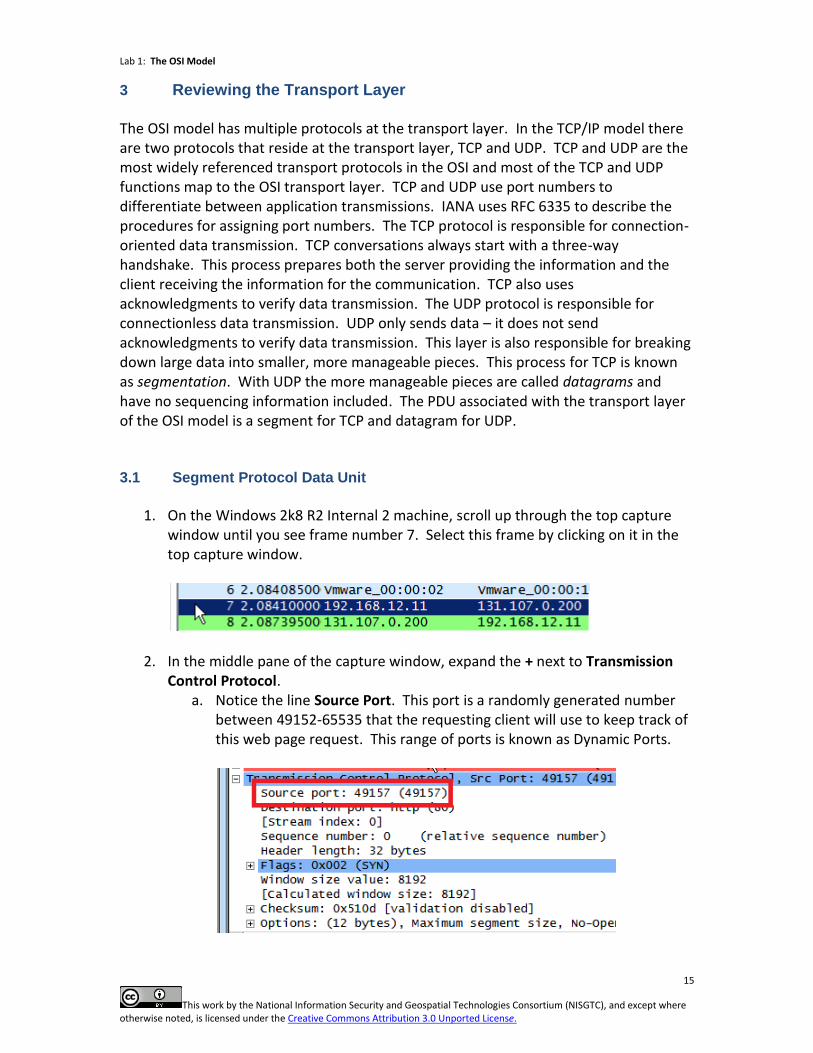
2. In the middle pane of the capture window, expand the + next to Transmission Control Protocol.
a. Notice the line Source Port. This port is a randomly generated number between 49152-65535 that the requesting client will use to keep track of this web page request. This range of ports is known as Dynamic Ports.
Lab 1: The OSI Model
16
This work by the National Information Security and Geospatial Technologies Consortium (NISGTC), and except where otherwise noted, is licensed under the Creative Commons Attribution 3.0 Unported License.
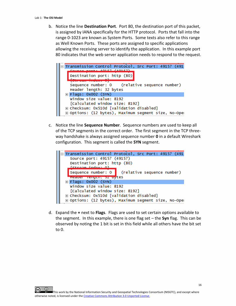
b. Notice the line Destination Port. Port 80, the destination port of this packet, is assigned by IANA specifically for the HTTP protocol. Ports that fall into the range 0-1023 are known as System Ports. Some texts also refer to this range as Well Known Ports. These ports are assigned to specific applications allowing the receiving server to identify the application. In this example port 80 indicates that the web server application needs to respond to the request.
c. Notice the line Sequence Number. Sequence numbers are used to keep all of the TCP segments in the correct order. The first segment in the TCP three-way handshake is always assigned sequence number 0 in a default Wireshark configuration. This segment is called the SYN segment.
d. Expand the + next to Flags. Flags are used to set certain options available to the segment. In this example, there is one flag set – the Syn flag. This can be observed by noting the 1 bit is set in this field while all others have the bit set to 0.
Lab 1: The OSI Model
17
This work by the National Information Security and Geospatial Technologies Consortium (NISGTC), and except where otherwise noted, is licensed under the Creative Commons Attribution 3.0 Unported License.
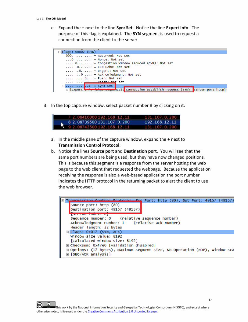
e. Expand the + next to the line Syn: Set. Notice the line Expert Info. The purpose of this flag is explained. The SYN segment is used to request a connection from the client to the server.
3. In the top capture window, select packet number 8 by clicking on it.
a. In the middle pane of the capture window, expand the + next to
Transmission Control Protocol. b. Notice the lines Source port and Destination port. You will see that the
same port numbers are being used, but they have now changed positions. This is because this segment is a response from the server hosting the web page to the web client that requested the webpage. Because the application receiving the response is also a web-based application the port number indicates the HTTP protocol in the returning packet to alert the client to use the web browser.
Lab 1: The OSI Model
18
This work by the National Information Security and Geospatial Technologies Consortium (NISGTC), and except where otherwise noted, is licensed under the Creative Commons Attribution 3.0 Unported License.
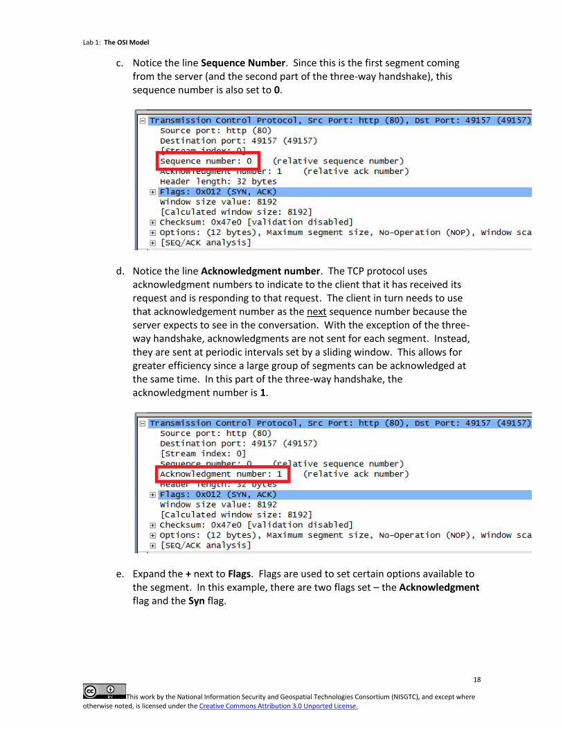
c. Notice the line Sequence Number. Since this is the first segment coming from the server (and the second part of the three-way handshake), this sequence number is also set to 0.
d. Notice the line Acknowledgment number. The TCP protocol uses acknowledgment numbers to indicate to the client that it has received its request and is responding to that request. The client in turn needs to use that acknowledgement number as the next sequence number because the server expects to see in the conversation. With the exception of the three-way handshake, acknowledgments are not sent for each segment. Instead, they are sent at periodic intervals set by a sliding window. This allows for greater efficiency since a large group of segments can be acknowledged at the same time. In this part of the three-way handshake, the acknowledgment number is 1.
e. Expand the + next to Flags. Flags are used to set certain options available to the segment. In this example, there are two flags set – the Acknowledgment flag and the Syn flag.
Lab 1: The OSI Model
19
This work by the National Information Security and Geospatial Technologies Consortium (NISGTC), and except where otherwise noted, is licensed under the Creative Commons Attribution 3.0 Unported License.
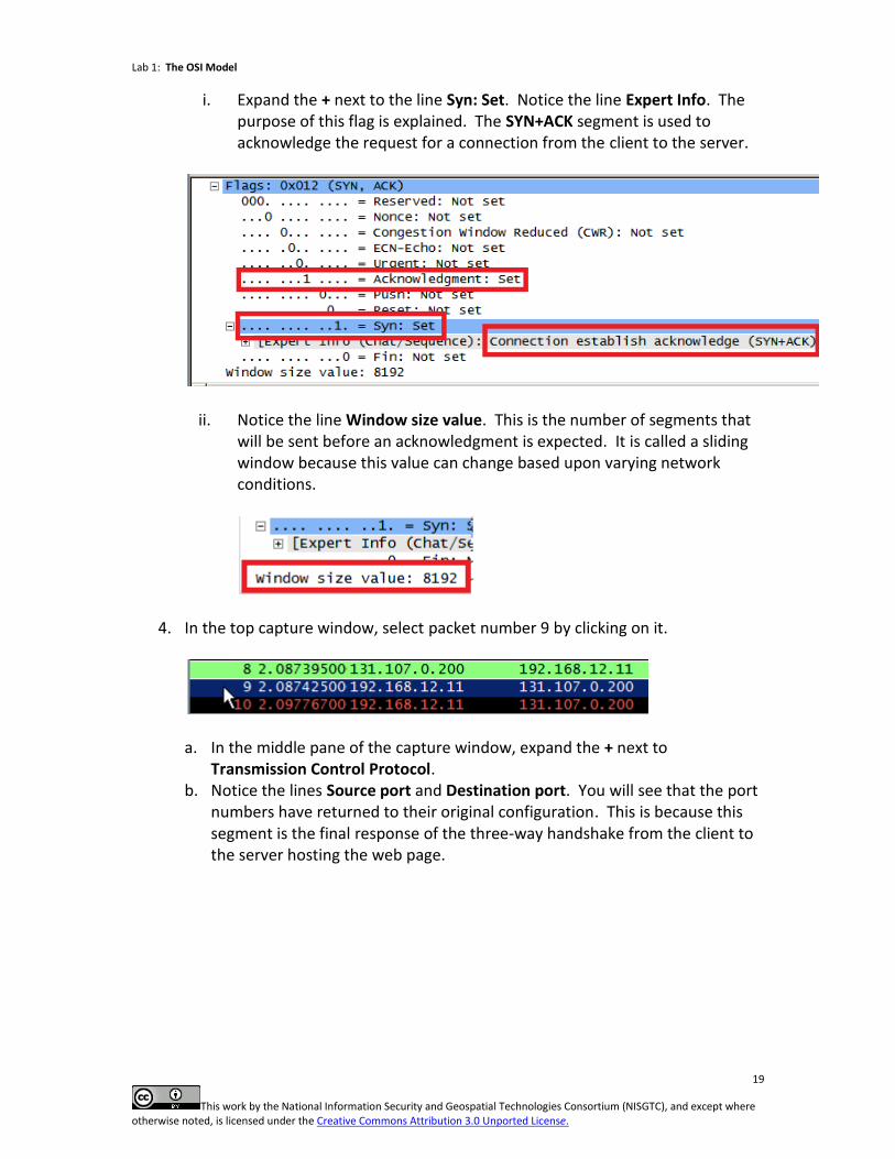
i. Expand the + next to the line Syn: Set. Notice the line Expert Info. The purpose of this flag is explained. The SYN+ACK segment is used to acknowledge the request for a connection from the client to the server.
ii. Notice the line Window size value. This is the number of segments that will be sent before an acknowledgment is expected. It is called a sliding window because this value can change based upon varying network conditions.
4. In the top capture window, select packet number 9 by clicking on it.
a. In the middle pane of the capture window, expand the + next to
Transmission Control Protocol. b. Notice the lines Source port and Destination port. You will see that the port
numbers have returned to their original configuration. This is because this segment is the final response of the three-way handshake from the client to the server hosting the web page.
Lab 1: The OSI Model
20
This work by the National Information Security and Geospatial Technologies Consortium (NISGTC), and except where otherwise noted, is licensed under the Creative Commons Attribution 3.0 Unported License.
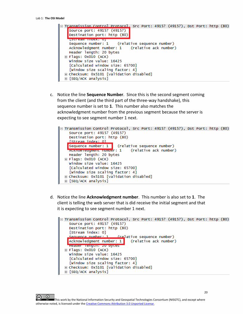
c. Notice the line Sequence Number. Since this is the second segment coming from the client (and the third part of the three-way handshake), this sequence number is set to 1. This number also matches the acknowledgment number from the previous segment because the server is expecting to see segment number 1 next.
d. Notice the line Acknowledgment number. This number is also set to 1. The client is telling the web server that is did receive the initial segment and that it is expecting to see segment number 1 next.
Lab 1: The OSI Model
21
This work by the National Information Security and Geospatial Technologies Consortium (NISGTC), and except where otherwise noted, is licensed under the Creative Commons Attribution 3.0 Unported License.
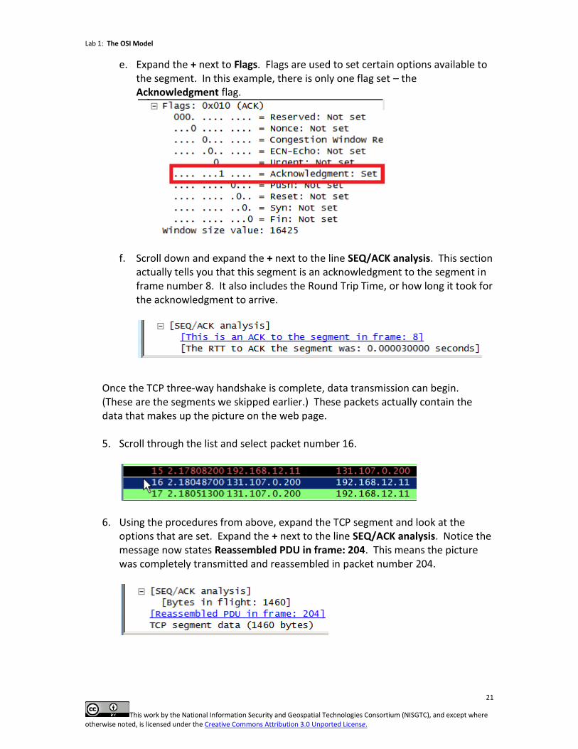
e. Expand the + next to Flags. Flags are used to set certain options available to the segment. In this example, there is only one flag set – the Acknowledgment flag.
f. Scroll down and expand the + next to the line SEQ/ACK analysis. This section actually tells you that this segment is an acknowledgment to the segment in frame number 8. It also includes the Round Trip Time, or how long it took for the acknowledgment to arrive.
Once the TCP three-way handshake is complete, data transmission can begin. (These are the segments we skipped earlier.) These packets actually contain the data that makes up the picture on the web page.
5. Scroll through the list and select packet number 16.
6. Using the procedures from above, expand the TCP segment and look at the options that are set. Expand the + next to the line SEQ/ACK analysis. Notice the message now states Reassembled PDU in frame: 204. This means the picture was completely transmitted and reassembled in packet number 204.
Lab 1: The OSI Model
22
This work by the National Information Security and Geospatial Technologies Consortium (NISGTC), and except where otherwise noted, is licensed under the Creative Commons Attribution 3.0 Unported License.
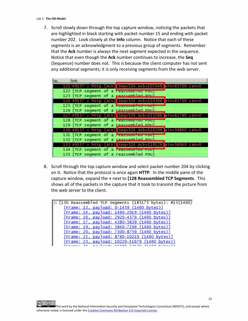
7. Scroll slowly down through the top capture window, noticing the packets that are highlighted in black starting with packet number 15 and ending with packet number 202. Look closely at the Info column. Notice that each of these segments is an acknowledgment to a previous group of segments. Remember that the Ack number is always the next segment expected in the sequence. Notice that even though the Ack number continues to increase, the Seq (Sequence) number does not. This is because the client computer has not sent any additional segments; it is only receiving segments from the web server.
8. Scroll through the top capture window and select packet number 204 by clicking on it. Notice that the protocol is once again HTTP. In the middle pane of the capture window, expand the + next to [128 Reassembled TCP Segments. This shows all of the packets in the capture that it took to transmit the picture from the web server to the client.
Lab 1: The OSI Model
23
This work by the National Information Security and Geospatial Technologies Consortium (NISGTC), and except where otherwise noted, is licensed under the Creative Commons Attribution 3.0 Unported License.
3.2 Conclusion
There are two protocols in the TCP/IP suite that reside at the transport layer of the OSI model – TCP and UDP. The TCP protocol is the transport layer protocol used by the HTTP protocol for reliable data transfer. TCP uses a three-way handshake to initiate a conversation then sequence and acknowledgment numbers to keep segments in the correct order during transmission. Port numbers are used to differentiate conversations. 3.3 Review Questions
1. In Section 3.1, Step 2a, what is the source port for the conversation?
2. In Section 3.1, Step 2b, what is the Well Known Port number for the HTTP
protocol?
3. Identify which flags are set in each segment of the three-way handshake. Segment 1: Segment 2: Segment 3:
4. The port number 49157 is known as this type of port because it is randomly generated when the conversation is initiated.
5. The port number 80 is known as this type of port because it is assigned to the HTTP protocol by IANA.
Lab 1: The OSI Model
24
This work by the National Information Security and Geospatial Technologies Consortium (NISGTC), and except where otherwise noted, is licensed under the Creative Commons Attribution 3.0 Unported License.
4 Reviewing the Network Layer
The network layer of the OSI model is responsible for logical addressing. These addresses are used by routers to move packets between networks. The major protocol of the TCP/IP suite that resides at this layer is the Internet Protocol, or IP. There are currently two versions of IP – 4 and 6. IP version 4 addresses are 32-bits in length and are represented in a dotted decimal notation. An example of an IPv4 address is 192.168.12.11. IP version 6 addresses are 128 bits in length and are represented in eight groups of four hexadecimal digits each. An example of an IPv6 address is 2001:0db8:85a3:0042:1000:8a2e:0370:7334. IPv6 is quickly becoming the new norm as the IPv4 address space has been exhausted. The PDU associated with the network layer is the packet. 4.1 The Packet Protocol Data Unit
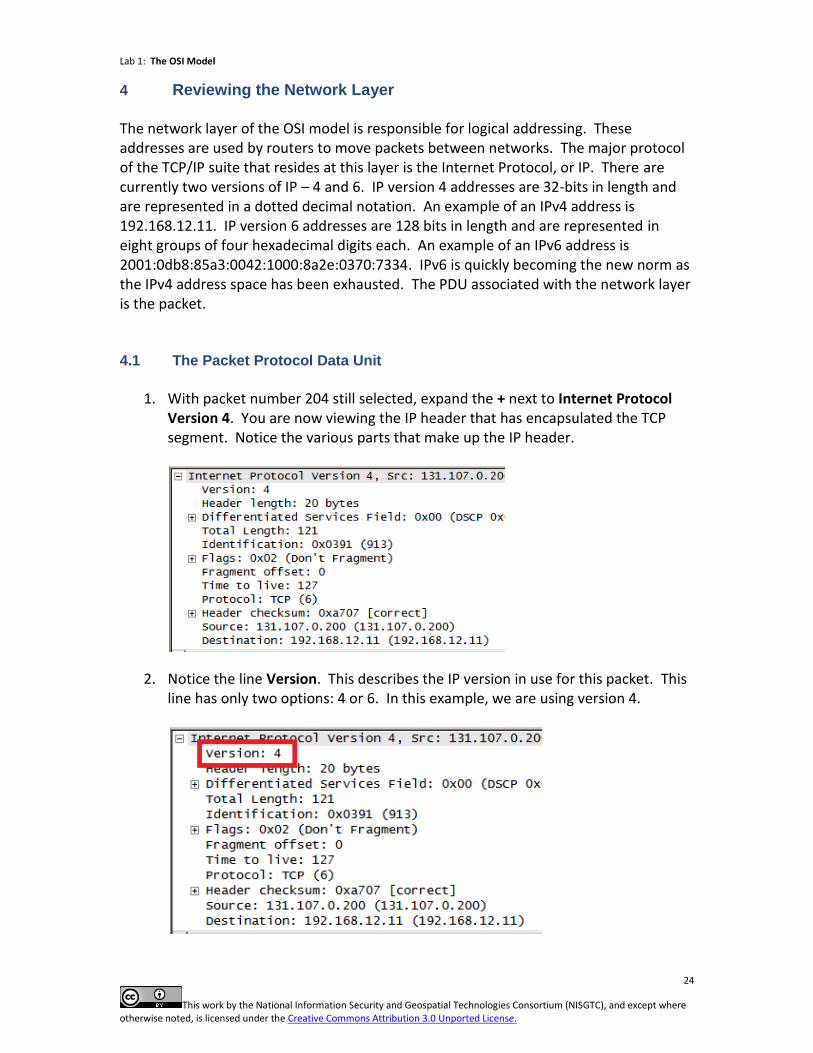
1. With packet number 204 still selected, expand the + next to Internet Protocol
Version 4. You are now viewing the IP header that has encapsulated the TCP segment. Notice the various parts that make up the IP header.
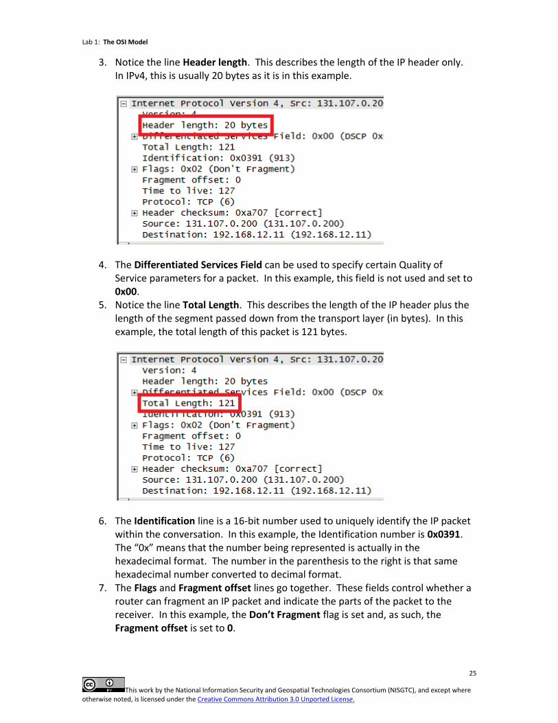
2. Notice the line Version. This describes the IP version in use for this packet. This line has only two options: 4 or 6. In this example, we are using version 4.
Lab 1: The OSI Model
25
This work by the National Information Security and Geospatial Technologies Consortium (NISGTC), and except where otherwise noted, is licensed under the Creative Commons Attribution 3.0 Unported License.
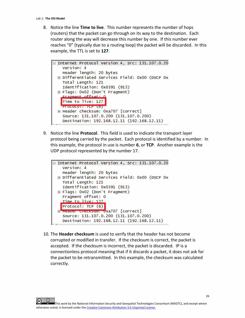
3. Notice the line Header length. This describes the length of the IP header only. In IPv4, this is usually 20 bytes as it is in this example.
4. The Differentiated Services Field can be used to specify certain Quality of Service parameters for a packet. In this example, this field is not used and set to 0x00.
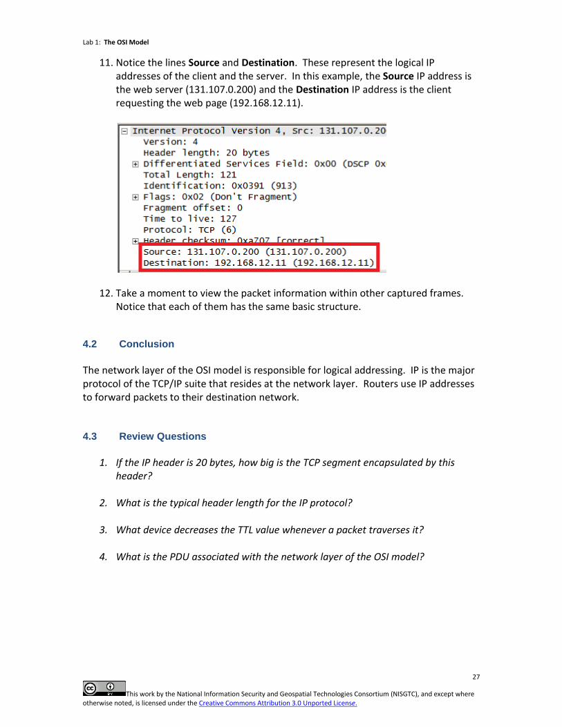
5. Notice the line Total Length. This describes the length of the IP header plus the length of the segment passed down from the transport layer (in bytes). In this example, the total length of this packet is 121 bytes.
6. The Identification line is a 16-bit number used to uniquely identify the IP packet within the conversation. In this example, the Identification number is 0x0391. The “0x” means that the number being represented is actually in the hexadecimal format. The number in the parenthesis to the right is that same hexadecimal number converted to decimal format.
7. The Flags and Fragment offset lines go together. These fields control whether a router can fragment an IP packet and indicate the parts of the packet to the receiver. In this example, the Don’t Fragment flag is set and, as such, the Fragment offset is set to 0.
Lab 1: The OSI Model
26
This work by the National Information Security and Geospatial Technologies Consortium (NISGTC), and except where otherwise noted, is licensed under the Creative Commons Attribution 3.0 Unported License.
8. Notice the line Time to live. This number represents the number of hops (routers) that the packet can go through on its way to the destination. Each router along the way will decrease this number by one. If this number ever reaches “0” (typically due to a routing loop) the packet will be discarded. In this example, the TTL is set to 127.
9. Notice the line Protocol. This field is used to indicate the transport layer protocol being carried by the packet. Each protocol is identified by a number. In this example, the protocol in use is number 6, or TCP. Another example is the UDP protocol represented by the number 17.
10. The Header checksum is used to verify that the header has not become corrupted or modified in transfer. If the checksum is correct, the packet is accepted. If the checksum is incorrect, the packet is discarded. IP is a connectionless protocol meaning that if it discards a packet, it does not ask for the packet to be retransmitted. In this example, the checksum was calculated correctly.
Lab 1: The OSI Model
27
This work by the National Information Security and Geospatial Technologies Consortium (NISGTC), and except where otherwise noted, is licensed under the Creative Commons Attribution 3.0 Unported License.
11. Notice the lines Source and Destination. These represent the logical IP addresses of the client and the server. In this example, the Source IP address is the web server (131.107.0.200) and the Destination IP address is the client requesting the web page (192.168.12.11).
12. Take a moment to view the packet information within other captured frames.
Notice that each of them has the same basic structure.
4.2 Conclusion
The network layer of the OSI model is responsible for logical addressing. IP is the major protocol of the TCP/IP suite that resides at the network layer. Routers use IP addresses to forward packets to their destination network. 4.3 Review Questions
1. If the IP header is 20 bytes, how big is the TCP segment encapsulated by this
header?
2. What is the typical header length for the IP protocol?
3. What device decreases the TTL value whenever a packet traverses it?
4. What is the PDU associated with the network layer of the OSI model?
Lab 1: The OSI Model
28
This work by the National Information Security and Geospatial Technologies Consortium (NISGTC), and except where otherwise noted, is licensed under the Creative Commons Attribution 3.0 Unported License.
5 Reviewing the Data Link Layer
The data link layer of the OSI model is responsible for physical addressing. These addresses are used by devices such as switches to move frames between nodes on the same network. One of the most common protocols that reside at this layer of the OSI model is Ethernet. Ethernet uses Media Access Control, or MAC, addresses burned into the ROM of network cards (NIC) to address its frames. MAC addresses are 48 bits, or 6 bytes, in length and are unique to every NIC. The PDU associated with the data link layer of the OSI model is the frame. 5.1 Frame Protocol Data Unit
1. Continuing from the previous task, select packet number 204 in the top capture
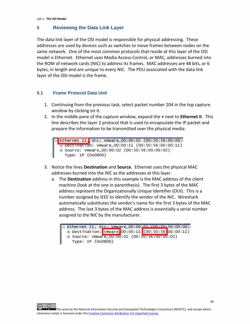
window by clicking on it. 2. In the middle pane of the capture window, expand the + next to Ethernet II. This
line describes the layer 2 protocol that is used to encapsulate the IP packet and prepare the information to be transmitted over the physical media.
3. Notice the lines Destination and Source. Ethernet uses the physical MAC addresses burned into the NIC as the addresses at this layer. a. The Destination address in this example is the MAC address of the client
machine (look at the one in parenthesis). The first 3 bytes of the MAC address represent the Organizationally Unique Identifier (OUI). This is a number assigned by IEEE to identify the vendor of the NIC. Wireshark automatically substitutes the vendor’s name for the first 3 bytes of the MAC address. The last 3 bytes of the MAC address is essentially a serial number assigned to the NIC by the manufacturer.
Lab 1: The OSI Model
29
This work by the National Information Security and Geospatial Technologies Consortium (NISGTC), and except where otherwise noted, is licensed under the Creative Commons Attribution 3.0 Unported License.
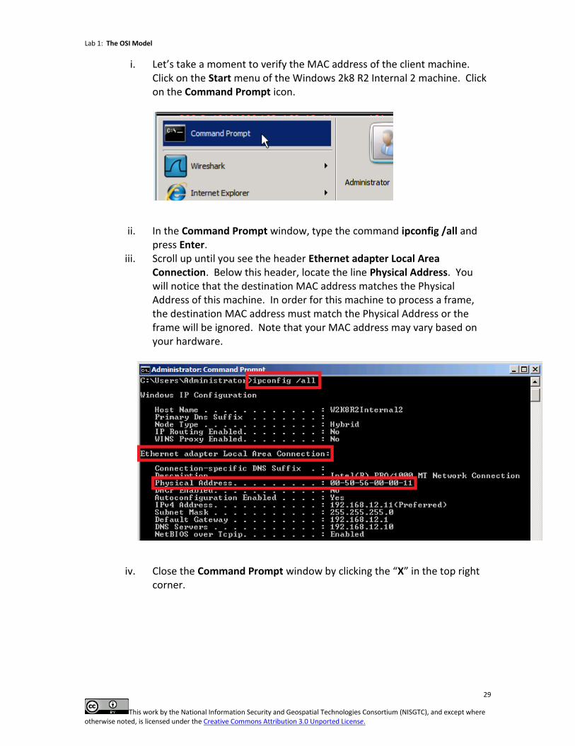
i. Let’s take a moment to verify the MAC address of the client machine. Click on the Start menu of the Windows 2k8 R2 Internal 2 machine. Click on the Command Prompt icon.
ii. In the Command Prompt window, type the command ipconfig /all and press Enter.
iii. Scroll up until you see the header Ethernet adapter Local Area Connection. Below this header, locate the line Physical Address. You will notice that the destination MAC address matches the Physical Address of this machine. In order for this machine to process a frame, the destination MAC address must match the Physical Address or the frame will be ignored. Note that your MAC address may vary based on your hardware.
iv. Close the Command Prompt window by clicking the “X” in the top right corner.
Lab 1: The OSI Model
30
This work by the National Information Security and Geospatial Technologies Consortium (NISGTC), and except where otherwise noted, is licensed under the Creative Commons Attribution 3.0 Unported License.
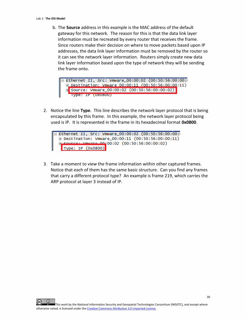
b. The Source address in this example is the MAC address of the default gateway for this network. The reason for this is that the data link layer information must be recreated by every router that receives the frame. Since routers make their decision on where to move packets based upon IP addresses, the data link layer information must be removed by the router so it can see the network layer information. Routers simply create new data link layer information based upon the type of network they will be sending the frame onto.
2. Notice the line Type. This line describes the network layer protocol that is being encapsulated by this frame. In this example, the network layer protocol being used is IP. It is represented in the frame in its hexadecimal format 0x0800.
3. Take a moment to view the frame information within other captured frames. Notice that each of them has the same basic structure. Can you find any frames that carry a different protocol type? An example is frame 219, which carries the ARP protocol at layer 3 instead of IP.
Lab 1: The OSI Model
31
This work by the National Information Security and Geospatial Technologies Consortium (NISGTC), and except where otherwise noted, is licensed under the Creative Commons Attribution 3.0 Unported License.
5.2 Conclusion
The data link layer of the OSI model is responsible for physical addressing. Ethernet switches and hosts use MAC addresses to move frames between nodes on the same network. 5.3 Review Questions
1. How long is a MAC address in bits?
2. How long is a MAC address in bytes?
3. What is the first half of a MAC address known as?
4. What command can be used on a Windows machine to view the MAC address?
Lab 1: The OSI Model
32
This work by the National Information Security and Geospatial Technologies Consortium (NISGTC), and except where otherwise noted, is licensed under the Creative Commons Attribution 3.0 Unported License.
6 Reviewing the Physical Layer
The physical layer of the OSI model incorporates all of the tangible network components such as cables, connectors and repeaters. The electronic signals on the media are also included in this layer. The electronic signals make the 1’s and 0’s that physically represent the data on the media. The PDU associated with the physical layer of the OSI model is simply bits. 6.1 Bit Protocol Data Unit
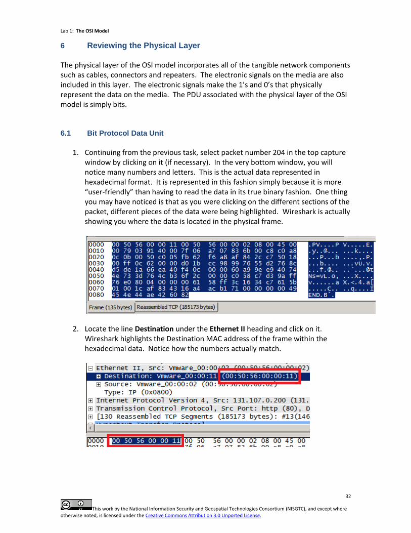
1. Continuing from the previous task, select packet number 204 in the top capture
window by clicking on it (if necessary). In the very bottom window, you will notice many numbers and letters. This is the actual data represented in hexadecimal format. It is represented in this fashion simply because it is more “user-friendly” than having to read the data in its true binary fashion. One thing you may have noticed is that as you were clicking on the different sections of the packet, different pieces of the data were being highlighted. Wireshark is actually showing you where the data is located in the physical frame.
2. Locate the line Destination under the Ethernet II heading and click on it. Wireshark highlights the Destination MAC address of the frame within the hexadecimal data. Notice how the numbers actually match.
Lab 1: The OSI Model
33
This work by the National Information Security and Geospatial Technologies Consortium (NISGTC), and except where otherwise noted, is licensed under the Creative Commons Attribution 3.0 Unported License.
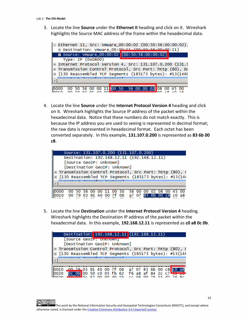
3. Locate the line Source under the Ethernet II heading and click on it. Wireshark highlights the Source MAC address of the frame within the hexadecimal data.
4. Locate the line Source under the Internet Protocol Version 4 heading and click on it. Wireshark highlights the Source IP address of the packet within the hexadecimal data. Notice that these numbers do not match exactly. This is because the IP address you are used to seeing is represented in decimal format; the raw data is represented in hexadecimal format. Each octet has been converted separately. In this example, 131.107.0.200 is represented as 83 6b 00 c8.
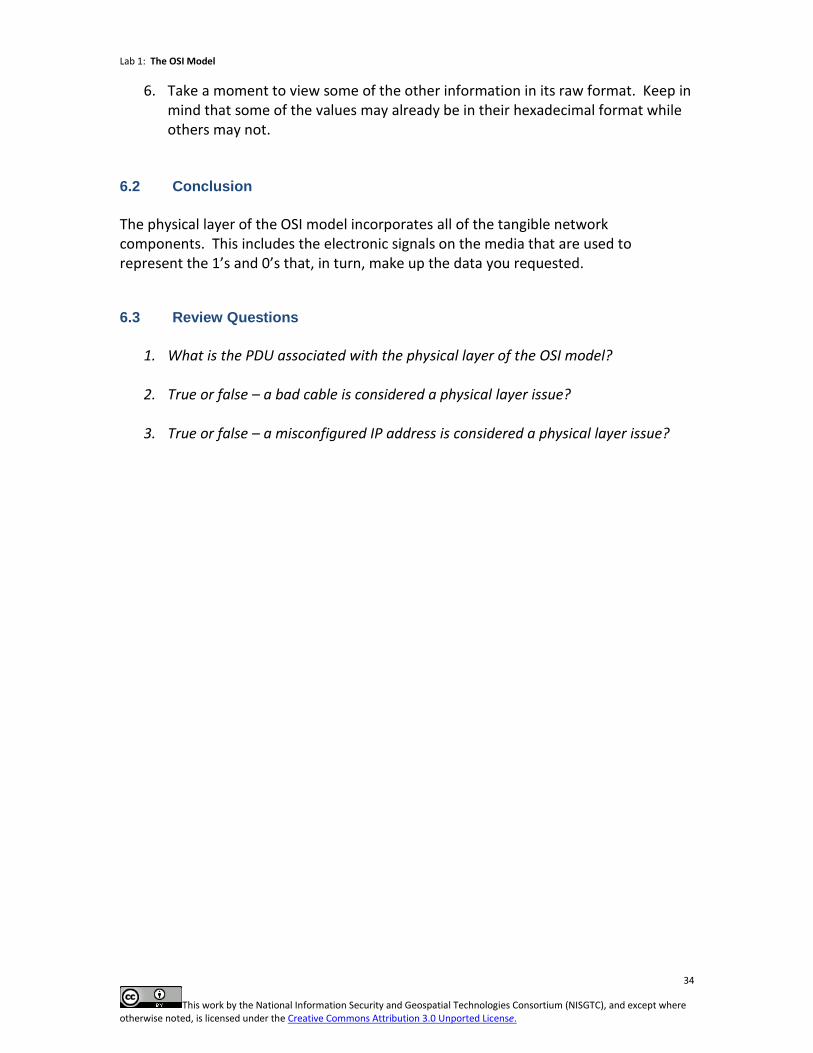
5. Locate the line Destination under the Internet Protocol Version 4 heading. Wireshark highlights the Destination IP address of the packet within the hexadecimal data. In this example, 192.168.12.11 is represented as c0 a8 0c 0b.
Lab 1: The OSI Model
34
This work by the National Information Security and Geospatial Technologies Consortium (NISGTC), and except where otherwise noted, is licensed under the Creative Commons Attribution 3.0 Unported License.
6. Take a moment to view some of the other information in its raw format. Keep in mind that some of the values may already be in their hexadecimal format while others may not.
6.2 Conclusion
The physical layer of the OSI model incorporates all of the tangible network components. This includes the electronic signals on the media that are used to represent the 1’s and 0’s that, in turn, make up the data you requested.
6.3 Review Questions
1. What is the PDU associated with the physical layer of the OSI model?
2. True or false – a bad cable is considered a physical layer issue?
3. True or false – a misconfigured IP address is considered a physical layer issue?