Embed Size (px)
Citation preview
106 Bradrock Dr. Des Plaines, IL 60018-19671 www.lamarchemfg.com Tel: 847 299 1188 Fax: 847 299 3061
La Marche Manufacturing Company www.lamarchemfg.com
Solar Charge Controller MPPT
Installation and Operation Manual
ii
Solar Charge Controller Dimensions
Specification Summary System Voltage 12 Volts / 24 Volts Rated Battery Current 10/20/30 Amps Rated Load Current 10 Amps (Optional) Max. Input Voltage** 22.5 Volts/ 45 Volts Nominal Input Power 12 Volt System 150 Watts 24 Volt System 300 Watts
** Array voltage should never exceed maximum input voltage. Refer PV data sheet to determine Voc before making connections
iii
Table of Contents
Solar Charge Controller Dimensions ............................................................................................... ii
Table of Contents ........................................................................................................................ iii
1 Important Safety Instructions ................................................................................................ 1
2 General Information ............................................................................................................. 1
2.1 Overview ....................................................................................................................... 1
2.2 Features ........................................................................................................................ 2
3 Installation Instructions ........................................................................................................ 3
3.1 General Installation Notes ............................................................................................... 3
3.2 Mounting ....................................................................................................................... 4
3.3 Wiring ........................................................................................................................... 5
4 Operation ............................................................................................................................ 9
4.1 LED Indications .............................................................................................................. 9
4.2 MPPT/PWM Technology .................................................................................................. 9
4.3 Load Control Information .............................................................................................. 10
4.4 Protections ................................................................................................................... 11
4.5 Inspection and Maintenance .......................................................................................... 12

1
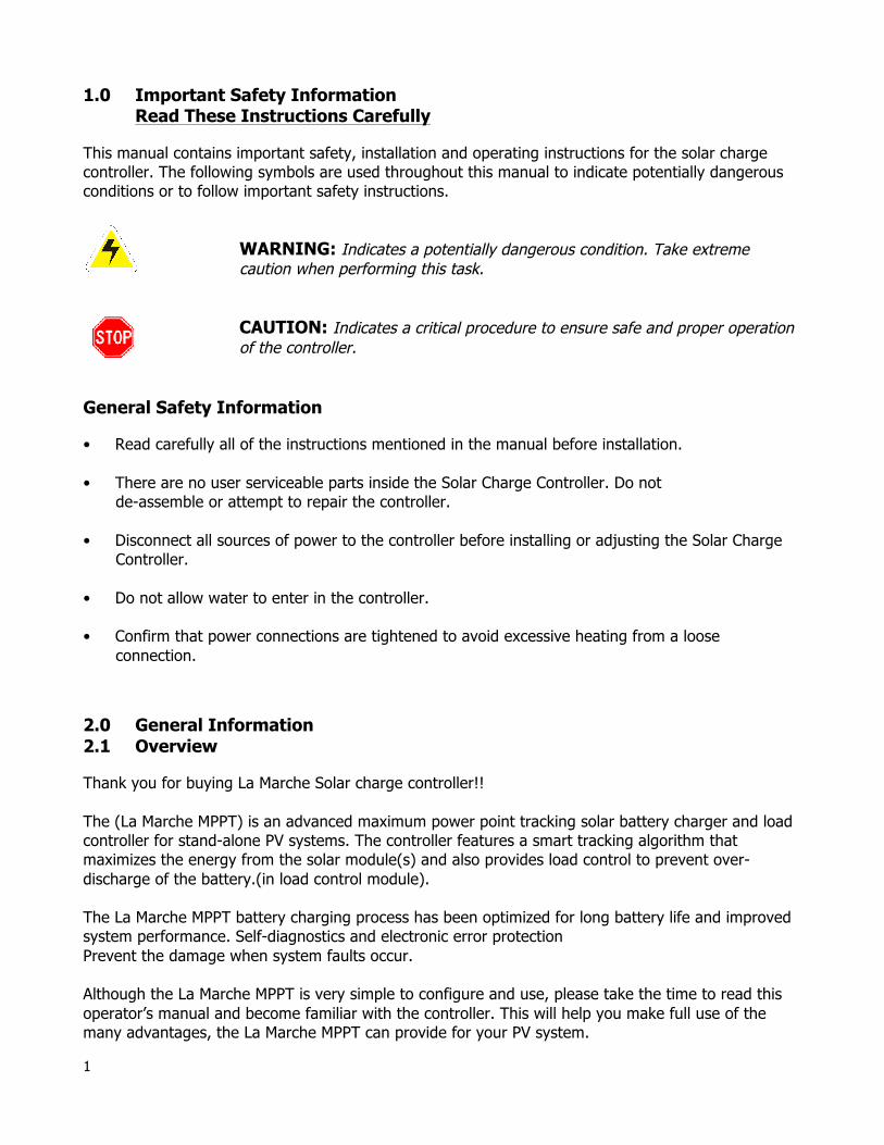
1.0 Important Safety Information Read These Instructions Carefully
This manual contains important safety, installation and operating instructions for the solar charge controller. The following symbols are used throughout this manual to indicate potentially dangerous conditions or to follow important safety instructions.
WARNING: Indicates a potentially dangerous condition. Take extreme caution when performing this task.
CAUTION: Indicates a critical procedure to ensure safe and proper operation of the controller.
General Safety Information • Read carefully all of the instructions mentioned in the manual before installation. • There are no user serviceable parts inside the Solar Charge Controller. Do not
de-assemble or attempt to repair the controller. • Disconnect all sources of power to the controller before installing or adjusting the Solar Charge
Controller. • Do not allow water to enter in the controller. • Confirm that power connections are tightened to avoid excessive heating from a loose
connection.
2.0 General Information 2.1 Overview Thank you for buying La Marche Solar charge controller!! The (La Marche MPPT) is an advanced maximum power point tracking solar battery charger and load controller for stand-alone PV systems. The controller features a smart tracking algorithm that maximizes the energy from the solar module(s) and also provides load control to prevent over-discharge of the battery.(in load control module). The La Marche MPPT battery charging process has been optimized for long battery life and improved system performance. Self-diagnostics and electronic error protection Prevent the damage when system faults occur. Although the La Marche MPPT is very simple to configure and use, please take the time to read this operator’s manual and become familiar with the controller. This will help you make full use of the many advantages, the La Marche MPPT can provide for your PV system.
2
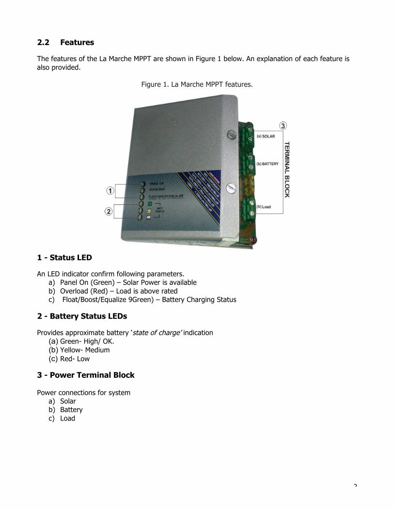
2.2 Features The features of the La Marche MPPT are shown in Figure 1 below. An explanation of each feature is also provided.
Figure 1. La Marche MPPT features.
1 - Status LED An LED indicator confirm following parameters.
a) Panel On (Green) – Solar Power is available b) Overload (Red) – Load is above rated c) Float/Boost/Equalize 9Green) – Battery Charging Status
2 - Battery Status LEDs Provides approximate battery ‘state of charge’ indication
(a) Green- High/ OK. (b) Yellow- Medium (c) Red- Low
3 - Power Terminal Block Power connections for system
a) Solar b) Battery c) Load
3
3.0 Installation Instructions 3.1 General Installation Notes • Read through the entire installation section first before beginning installation. • Be very careful when working with batteries. Wear eye protection. Have fresh water available to
wash and clean any contact with battery acid. • Use insulated tools and avoids placing metal objects near the batteries. • Explosive battery gases may be present during charging. Ensure that there is sufficient
ventilation to release the gases. • Do not install in locations where water can enter in the controller. • Loose power connections may result in resistive connections that melt wire Insulation, burn surrounding materials, or even causes fire. Ensure tight connections and use cable clamps to secure cables and prevent them from swaying in mobile applications. Load Control – Low Voltage Disconnect / Reconnect LVD = 10.80 V, LVR = 12.60 V LVD= Battery Low voltage Disconnect LVR = Battery Low Voltage Reconnect Auto-Equalization The Auto equalize feature will administer an equalization charge every 28 days.
4
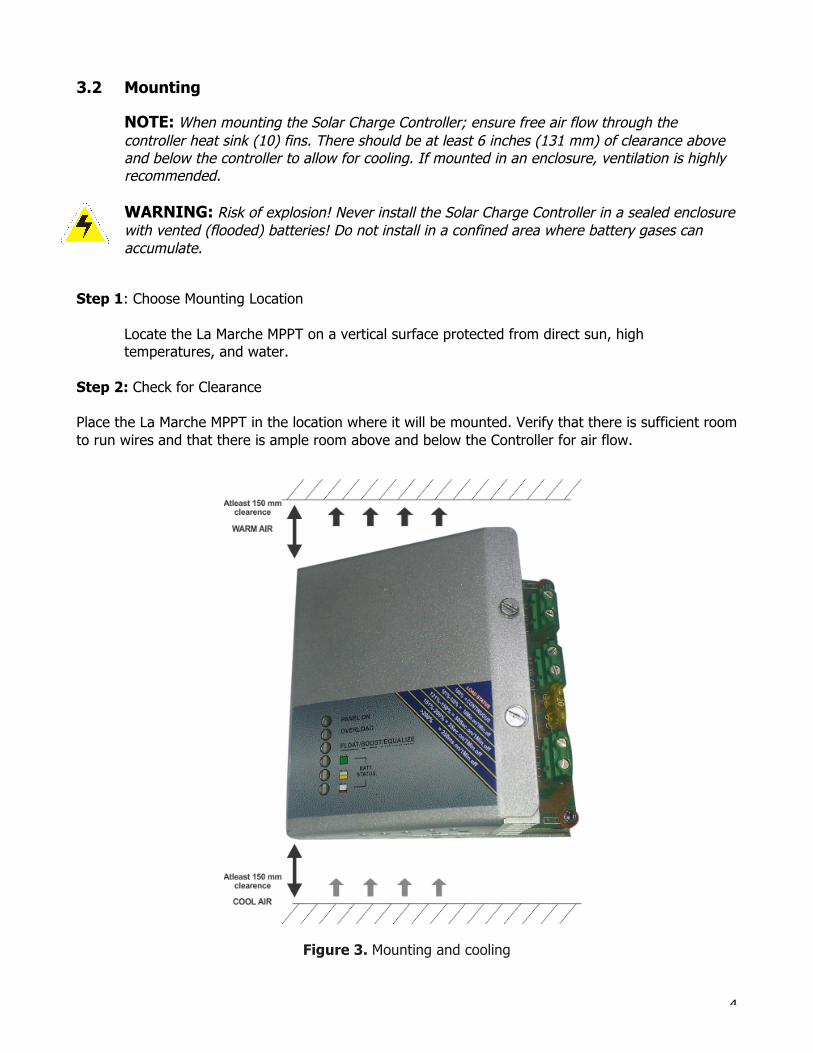
3.2 Mounting
NOTE: When mounting the Solar Charge Controller; ensure free air flow through the controller heat sink (10) fins. There should be at least 6 inches (131 mm) of clearance above and below the controller to allow for cooling. If mounted in an enclosure, ventilation is highly recommended. WARNING: Risk of explosion! Never install the Solar Charge Controller in a sealed enclosure with vented (flooded) batteries! Do not install in a confined area where battery gases can accumulate.
Step 1: Choose Mounting Location
Locate the La Marche MPPT on a vertical surface protected from direct sun, high temperatures, and water.
Step 2: Check for Clearance Place the La Marche MPPT in the location where it will be mounted. Verify that there is sufficient room to run wires and that there is ample room above and below the Controller for air flow.
Figure 3. Mounting and cooling
5
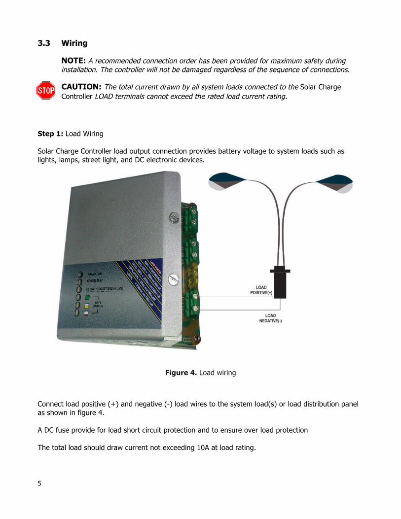
3.3 Wiring
NOTE: A recommended connection order has been provided for maximum safety during installation. The controller will not be damaged regardless of the sequence of connections. CAUTION: The total current drawn by all system loads connected to the Solar Charge Controller LOAD terminals cannot exceed the rated load current rating.
Step 1: Load Wiring Solar Charge Controller load output connection provides battery voltage to system loads such as lights, lamps, street light, and DC electronic devices.
Figure 4. Load wiring Connect load positive (+) and negative (-) load wires to the system load(s) or load distribution panel as shown in figure 4. A DC fuse provide for load short circuit protection and to ensure over load protection The total load should draw current not exceeding 10A at load rating.
6
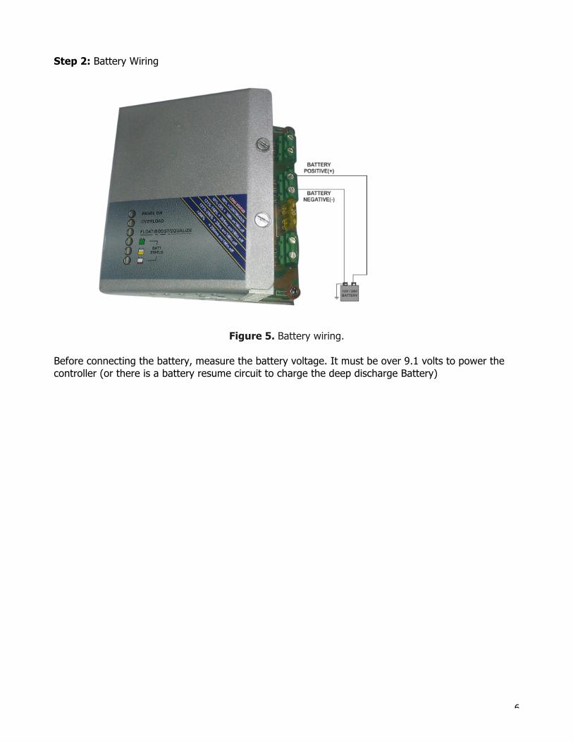
Step 2: Battery Wiring
Figure 5. Battery wiring. Before connecting the battery, measure the battery voltage. It must be over 9.1 volts to power the controller (or there is a battery resume circuit to charge the deep discharge Battery)
7
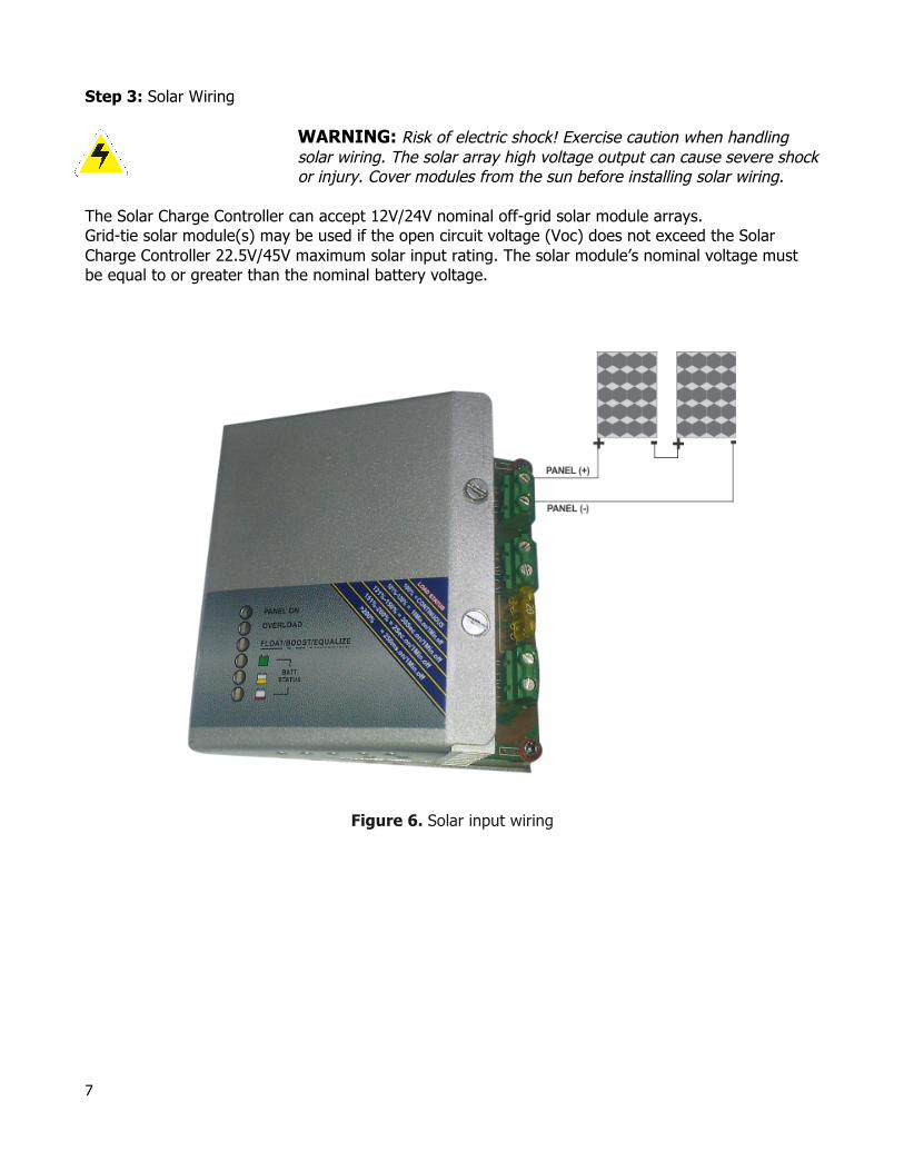
Step 3: Solar Wiring
WARNING: Risk of electric shock! Exercise caution when handling solar wiring. The solar array high voltage output can cause severe shock or injury. Cover modules from the sun before installing solar wiring.
The Solar Charge Controller can accept 12V/24V nominal off-grid solar module arrays. Grid-tie solar module(s) may be used if the open circuit voltage (Voc) does not exceed the Solar Charge Controller 22.5V/45V maximum solar input rating. The solar module’s nominal voltage must be equal to or greater than the nominal battery voltage.
Figure 6. Solar input wiring
8
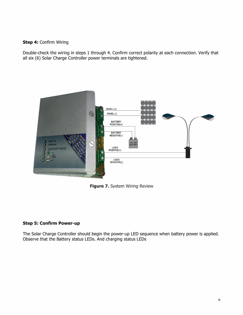
Step 4: Confirm Wiring Double-check the wiring in steps 1 through 4. Confirm correct polarity at each connection. Verify that all six (6) Solar Charge Controller power terminals are tightened.
Figure 7. System Wiring Review
+ - 2 1 3 Step 5: Confirm Power-up The Solar Charge Controller should begin the power-up LED sequence when battery power is applied. Observe that the Battery status LEDs. And charging status LEDs
9
4.0 Operation 4.1 LED Indicators STATUS LED: The Status LED indicates charging status and any existing solar input connected/ disconnected conditions. The Status LED is on when charging during the day and off at night. One LED will remain ON to show battery status. LED CONDITIONS: (1) LED1 (GREEN): “ON” WHEN PANEL CONNECTED / ”OFF” WHEN DISCONNECTED. (2) LED2 (RED): BLINKING WHEN OVERLOAD. (3) LED3 (GREEN): FLOAT/BOOST --- BLINKING AT BOOST, SLOW BLINKING AT FLOAT. (4) BATTERY LEVEL INDICATIONS:- (A) BATTERY FULL “ON” GREEN LED. (B) BATTERY MEDIUM “ON” YELLOW LED. (C) BATTERY LOW “ON” RED LED.
4.2 La Marche MPPT Technology The La Marche MPPT utilizes Maximum Power Point Tracking technology to extract maximum power from the solar module(s). The tracking algorithm is fully automatic and does not require user adjustment. La Marche MPPT technology will track the array maximum power point voltage (Vmp) as it varies with weather conditions, ensuring that maximum power is harvested from the array through the course of the day. Current Boost If the solar module’s Vmp is greater than the battery voltage, the battery current must be proportionally greater than the solar input current so that input and output power are balanced. An Advantage Over Traditional Controllers Traditional controllers connect the solar module directly to the battery when recharging. This requires that the solar module operates in a voltage range that is below the module’s Vmp. In a 12 V system, for example, the battery voltage may range from 10 - 15 Vdc but the module’s Vmp is typically around 17V. Figure 8 shows a typical Current vs Voltage output curve for a nominal 12V off-grid module.
10
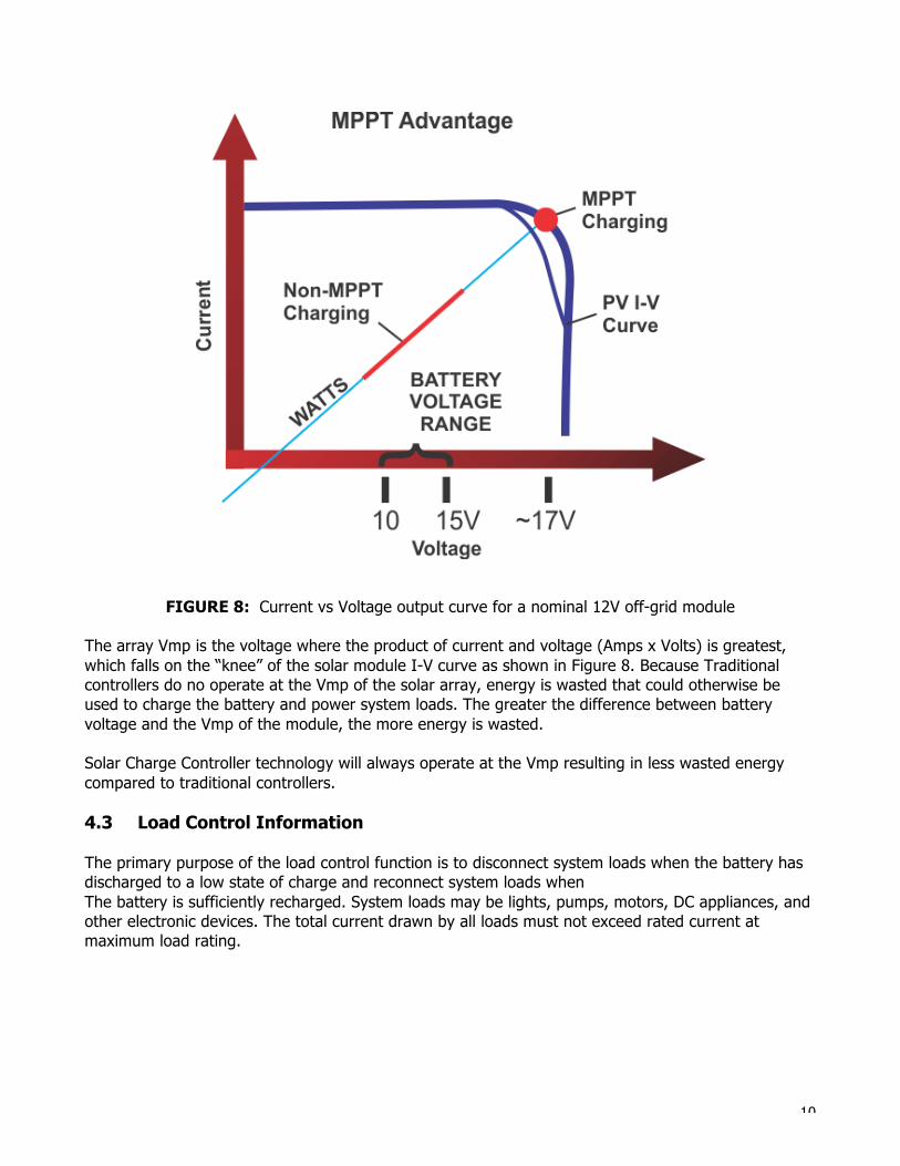
FIGURE 8: Current vs Voltage output curve for a nominal 12V off-grid module The array Vmp is the voltage where the product of current and voltage (Amps x Volts) is greatest, which falls on the “knee” of the solar module I-V curve as shown in Figure 8. Because Traditional controllers do no operate at the Vmp of the solar array, energy is wasted that could otherwise be used to charge the battery and power system loads. The greater the difference between battery voltage and the Vmp of the module, the more energy is wasted. Solar Charge Controller technology will always operate at the Vmp resulting in less wasted energy compared to traditional controllers. 4.3 Load Control Information The primary purpose of the load control function is to disconnect system loads when the battery has discharged to a low state of charge and reconnect system loads when The battery is sufficiently recharged. System loads may be lights, pumps, motors, DC appliances, and other electronic devices. The total current drawn by all loads must not exceed rated current at maximum load rating.
11
CAUTION: Do not wire an AC inverter of any size to the load terminals of the Solar Charge Controller. Damage to the load control circuit may occur. Wire inverters directly to the battery or battery bank.
Load Control Settings Load control is fully automatic. Choose between two (2) factory Low Voltage Disconnect (LVD) and Low Voltage Reconnect (LVR). LVD Warning As the battery discharges, the Battery Status LEDs will transition from green to yellow and then from yellow to solid red. The solid red indication is a warning that a low voltage disconnect event will occur soon. After that buzzer will START at 11.2V. Load disconnect depends on many factors including: • Rate of discharge (amount of load drawn) • Capacity of the battery • Health of the battery • LVD set point (10.8V) If the battery discharges to the LVD set point, the load will disconnect and a solid red Battery Status LED indication will be displayed. • Exercise caution when connecting loads with specific polarity to a live load circuit. A reverse
polarity connection may damage the load. Always double check load connections before applying power.
4.4 Protections Solar Overload (No LED indication) The Solar Charge Controller will limit battery current to the 10A /20A/30A maximum rating. An over-sized solar array will not operate at peak power. The solar array should be less than the Solar Charge Controller nominal maximum input power rating for optimal performance. Overload If the load current exceeds the maximum load current rating (10A), the Solar Charge Controller will disconnect the load. The Solar Charge Controller will attempt to reconnect until the load is reduced or disconnect.
12
Load Short Circuit Fully protected against load wiring short-circuits. Load will be OFF until the fuse is replaced. Battery Reverse Polarity (No LED indication fully protected against reverse battery connection. There will be no damage to the controller. DC fuse will be blown “OFF”. 4.5 Inspection and Maintenance The following inspections and maintenance tasks are recommended at least two times per year for best controller performance: • Tighten all terminals. Inspect for loose, broken, or corroded connections. • Verify that all wire clamps and tie-downs are secure. • Check that the controller is mounted in a clean, protected environment; free of dirt, insects,
nests, and corrosion. • If applicable, check enclosure ventilation and air flow holes for obstructions. • Verify that LED indications are consistent with the present system conditions.