Embed Size (px)
Citation preview
SORMAT PDS-Drop-in-anchors-OPT7_EN-2018-01-12
LA
+, L
AL+
, LA
H D
RO
P IN
AN
CH
OR
S
1
PRODUCT DATA SHEET
SINGLE ANCHOR USE FOR NON-CRACKED CONCRETE
www.sormat.com
facebook.com/sormat
youtube.com/sormatfixing
LA+ LAL+ LAH
DROP IN ANCHORS
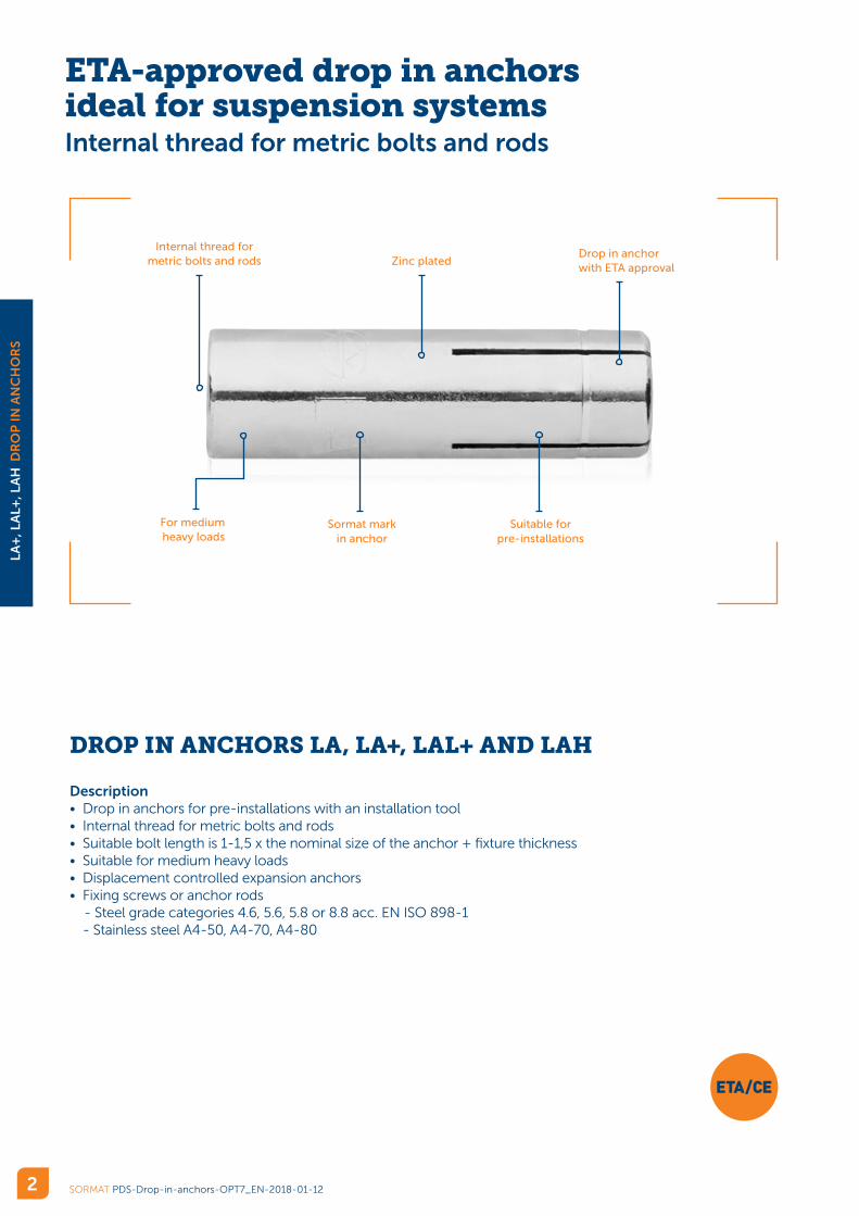
ETA-approved drop in anchors ideal for suspension systems Internal thread for metric bolts and rods
SORMAT PDS-Drop-in-anchors-OPT7_EN-2018-01-12
LA
+, L
AL+
, LA
H D
RO
P IN
AN
CH
OR
S
2
DROP IN ANCHORS LA, LA+, LAL+ AND LAH
Description• Drop in anchors for pre-installations with an installation tool• Internal thread for metric bolts and rods• Suitable bolt length is 1-1,5 x the nominal size of the anchor + fixture thickness• Suitable for medium heavy loads• Displacement controlled expansion anchors• Fixing screws or anchor rods
- Steel grade categories 4.6, 5.6, 5.8 or 8.8 acc. EN ISO 898-1 - Stainless steel A4-50, A4-70, A4-80
Sormat markin anchor
Suitable for pre-installations
For medium heavy loads
Drop in anchorwith ETA approval
Internal thread for metric bolts and rods Zinc plated
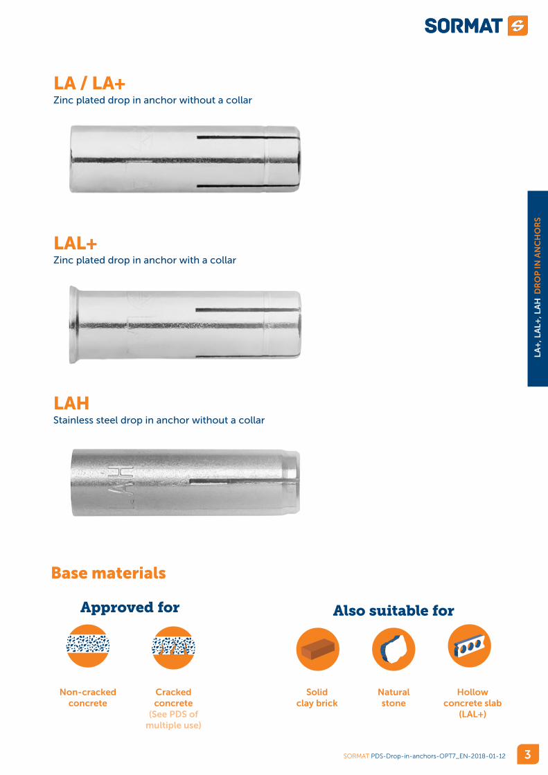
LA / LA+Zinc plated drop in anchor without a collar
LAL+Zinc plated drop in anchor with a collar
LAHStainless steel drop in anchor without a collar
SORMAT PDS-Drop-in-anchors-OPT7_EN-2018-01-12
LA
+, L
AL+
, LA
H D
RO
P IN
AN
CH
OR
S
3
Approved for Also suitable for
Cracked concrete
(See PDS of multiple use)
Solid clay brick
Hollow concrete slab
(LAL+)
Non-cracked concrete
Natural stone
Base materials
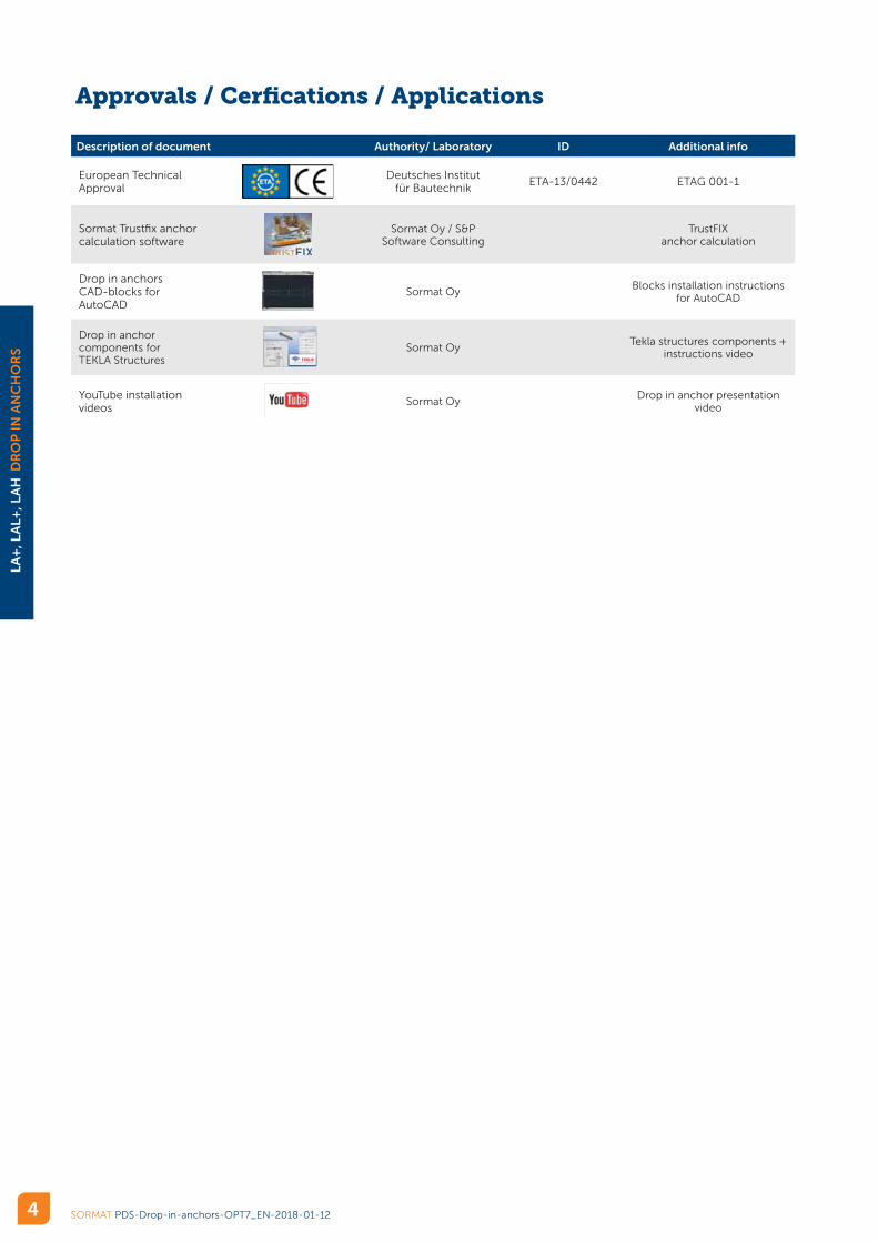
Approvals / Cerfications / Applications
Description of document Authority/ Laboratory ID Additional info
European Technical Approval
Deutsches Institut für Bautechnik
ETA-13/0442 ETAG 001-1
Sormat Trustfix anchor calculation software
Sormat Oy / S&P Software Consulting
TrustFIX anchor calculation
Drop in anchors CAD-blocks for AutoCAD
Sormat OyBlocks installation instructions
for AutoCAD
Drop in anchor components for TEKLA Structures
Sormat OyTekla structures components +
instructions video
YouTube installation videos
Sormat OyDrop in anchor presentation
video
SORMAT PDS-Drop-in-anchors-OPT7_EN-2018-01-12
LA
+, L
AL+
, LA
H D
RO
P IN
AN
CH
OR
S
4

Characteristic resistancesLA+ / LAL+ LA
Anchor size M6 x 25 M8 x 30 M10 x 40 M12 x 50 M16 x 65 M20 x 80
Approval - OPT 7 OPT 7 OPT 7 OPT 7 -
Effective anchorage depth hef [mm] 25 30 40 50 65 80
Non-cracked concrete
Tensile NRk [kN] 5,8 7,5 12,0 16,0 26,5 36,1
Shear VRk
[kN] 4,0* 7,3* 9,5* 15,4* 25,7* 49,0*
* Failure mode = STEEL
Design resistancesLA+ / LAL+ LA
Anchor size M6 x 25 M8 x 30 M10 x 40 M12 x 50 M16 x 65 M20 x 80
Approval - OPT 7 OPT 7 OPT 7 OPT 7 -
Effective anchorage depth hef [mm] 25 30 40 50 65 80
Non-cracked concrete
Tensile NRd [kN] 2,7 5,0 6,7 8,8 14,7 16,7
Shear VRd
[kN] 2,4* 4,3* 6,3* 10,2* 17,1* 29,4*
* Failure mode = STEEL
Recommended loadsLA+ / LAL+ LA
Anchor size M6 x 25 M8 x 30 M10 x 40 M12 x 50 M16 x 65 M20 x 80
Approval - OPT 7 OPT 7 OPT 7 OPT 7 -
Effective anchorage depth hef [mm] 25 30 40 50 65 80
Non-cracked concrete
Tensile Nrec [kN] 1,9 3,6 4,8 6,3 10,5 11,9
Shear Vrec
[kN] 1,7* 3,1* 4,5* 7,3* 12,2* 21,0*
* Failure mode = STEEL
The partial safety factor for action is γ = 1.4.
SORMAT PDS-Drop-in-anchors-OPT7_EN-2018-01-12
LA
+, L
AL+
, LA
H D
RO
P IN
AN
CH
OR
S
5
Static and quasi-static loads for LA, LA+, LAL+
The data of these tables is based on: • ETA-13/0442 • Non-cracked concrete C20/25, f
ck,cube = 25 N/mm²
• Installation has been done correctly (see page 8)• No influence of edge- and spacing distances (see page 11)• Respect of minimum base material thickness (see page 11)• Load values are based on screw or rod with steel grade 4.6

Characteristic resistancesLAH
Anchor size M6 x 25 M8 x 30 M10 x 40 M12 x 50 M16 x 65 M20 x 80
Approval - - - - - -
Effective anchorage depth hef [mm] 25 30 40 50 65 80
Non-cracked concrete
Tensile NRk [kN] 6,3 8,3 9,2 17,8 24,8 36,1
Shear VRk
[kN] 5,0* 9,2* 14,5* 21,1* 39,3* 61,3*
* Failure mode = STEEL
Design resistancesLAH
Anchor size M6 x 25 M8 x 30 M10 x 40 M12 x 50 M16 x 65 M20 x 80
Approval - - - - - -
Effective anchorage depth hef [mm] 25 30 40 50 65 80
Non-cracked concrete
Tensile NRd [kN] 2,9 3,8 4,2 8,2 11,5 16,7
Shear VRd
[kN] 2,1* 3,9* 6,1* 8,9* 16,5* 25,8*
* Failure mode = STEEL
Recommended loadsLAH
Anchor size M6 x 25 M8 x 30 M10 x 40 M12 x 50 M16 x 65 M20 x 80
Approval - - - - - -
Effective anchorage depth hef [mm] 25 30 40 50 65 80
Non-cracked concrete
Tensile Nrec [kN] 2,1 2,7 3,0 5,9 8,2 11,9
Shear Vrec
[kN] 1,5* 2,8* 4,4* 6,3* 11,8* 18,4*
* Failure mode = STEEL
The partial safety factor for action is γ = 1.4.
SORMAT PDS-Drop-in-anchors-OPT7_EN-2018-01-12
LA
+, L
AL+
, LA
H D
RO
P IN
AN
CH
OR
S
6
Static and quasi-static loads for single anchor LAH
The data of these tables is based on: • Non-cracked concrete C20/25, f
ck,cube = 25 N/mm²
• Installation has been done correctly (see page 8)• No influence of edge- and spacing distances (see page 11)• Respect of minimum base material thickness (see page 11)• Load values are based on screw or rod with steel strength A4-50
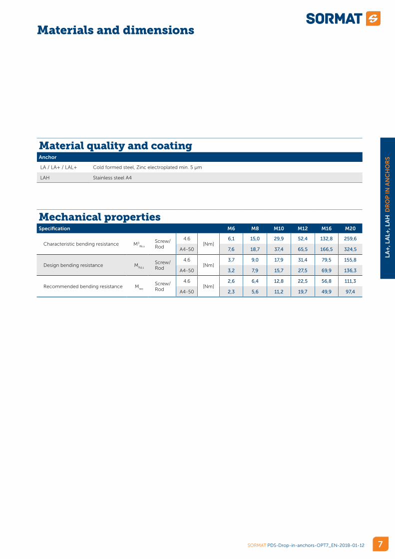
Mechanical properties Specification M6 M8 M10 M12 M16 M20
Characteristic bending resistance M0Rk,s
Screw/Rod
4.6[Nm]
6,1 15,0 29,9 52,4 132,8 259,6
A4-50 7,6 18,7 37,4 65,5 166,5 324,5
Design bending resistance MRd,s
Screw/Rod
4.6[Nm]
3,7 9,0 17,9 31,4 79,5 155,8
A4-50 3,2 7,9 15,7 27,5 69,9 136,3
Recommended bending resistance Mrec
Screw/Rod
4.6[Nm]
2,6 6,4 12,8 22,5 56,8 111,3
A4-50 2,3 5,6 11,2 19,7 49,9 97,4
Material quality and coatingAnchor
LA / LA+ / LAL+ Cold formed steel, Zinc electroplated min. 5 µm
LAH Stainless steel A4
SORMAT PDS-Drop-in-anchors-OPT7_EN-2018-01-12
LA
+, L
AL+
, LA
H D
RO
P IN
AN
CH
OR
S
7
Materials and dimensions
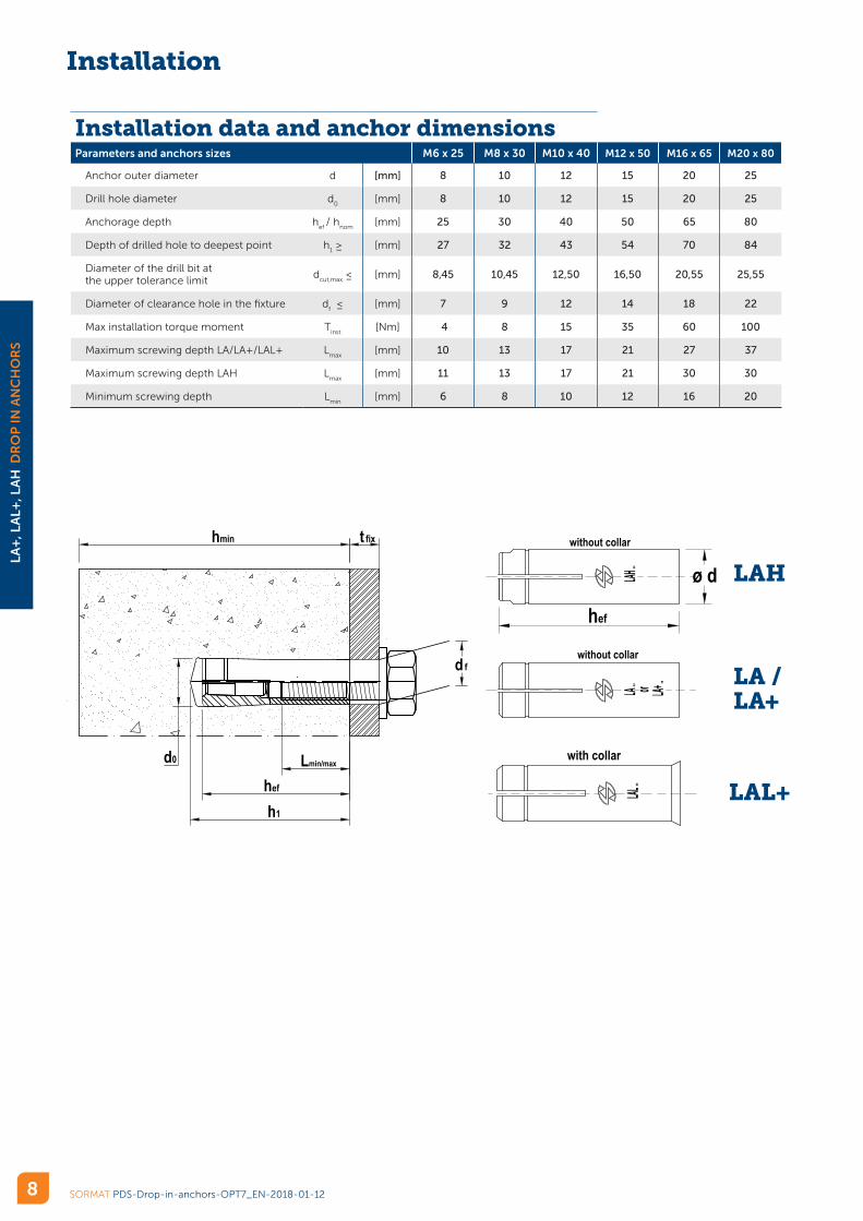
Installation data and anchor dimensionsParameters and anchors sizes M6 x 25 M8 x 30 M10 x 40 M12 x 50 M16 x 65 M20 x 80
Anchor outer diameter d [mm] 8 10 12 15 20 25
Drill hole diameter d0
[mm] 8 10 12 15 20 25
Anchorage depth hef
/ hnom
[mm] 25 30 40 50 65 80
Depth of drilled hole to deepest point h1 ≥ [mm] 27 32 43 54 70 84
Diameter of the drill bit at the upper tolerance limit
dcut,max
≤ [mm] 8,45 10,45 12,50 16,50 20,55 25,55
Diameter of clearance hole in the fixture df ≤ [mm] 7 9 12 14 18 22
Max installation torque moment Tinst
[Nm] 4 8 15 35 60 100
Maximum screwing depth LA/LA+/LAL+ Lmax
[mm] 10 13 17 21 27 37
Maximum screwing depth LAH Lmax
[mm] 11 13 17 21 30 30
Minimum screwing depth Lmin
[mm] 6 8 10 12 16 20
Installation
ø d
hef
with collar
without collar
without collar
Through installation
h1
d0
hmin t fix
Lmin/max
d f
hef
Through installation
SORMAT PDS-Drop-in-anchors-OPT7_EN-2018-01-12
LA
+, L
AL+
, LA
H D
RO
P IN
AN
CH
OR
S
8
LA /LA+
LAH
LAL+

SORMAT PDS-Drop-in-anchors-OPT7_EN-2018-01-12
LA
+, L
AL+
, LA
H D
RO
P IN
AN
CH
OR
S
9
Setting instructions
Installation equipmentSpecification M6 x 25 M8 x 30 M10 x 40 M12 x 50 M16 x 65 M20 x 80
Drill bitSDS+ 2-CUT or 4-CUT
8 10 12 15 20 25
Rotary hammer750…1200 r.p.m / 1.8 …3.3 J
360…550 r.p.m / 4,9 …11,5 J
Additional tools Air pump/compressor, LT+ or LT+ PRO Punch tool, hammer, torque wrench

REVISION HISTORYREV DESCRIPTION Date/By Approved by
SCALE
DRAWNCHECKED
NAMEjuhman
DATE17.10.2017
TITLE
SIZE
A3
DRAWINGNUMBER S000102 REV
A
LT+_Setting tools 6-16_for PDS.dft
WEIGHT:
SHEET 1 OF 1
Cop
yrig
ht b
y So
rmat
Oy.
All
right
s re
serv
ed. R
efer
to p
rote
ctio
n no
tice
ISO
160
16.
1:1
0,401 kg
Setting tools 6-16
MATERIAL SteelGRADE
Hardened 38-42 HRCSTRENGTH
COATING Zinc electroplatedacc. EN ISO 4042, bright passivated Cr+3
FILE NAME
REPLACES
THICKNESS > 5-8SURFACE HARDNESS
MAT. INFO1 Surface finish DIN ISO 1302
LT+
MAT. INFO2
ADD. INFO1 :
ADD. INFO2 :
Dimensionswithout tolerancein acc. with DIN
7168, middle
STANDARDµm
LT+ M6-M16-14-01
L3
L1 L2O
D3
O D
2
O D
1
Inspection criteria on manufacturing concernsall the dimensions below
SIZE(Marking)
D1± 0,1
H1± 0,5
D2± 0,3
H2± 2,0
D3± 0,3
H3± 3,0
D4± 0,3
M6 5 15 7,5 35 12 220 11M8 6,6 17,5 9,5 40 12 220 11
M10x25 8,3 17 12 0 12 213 11M10x40 8,3 23,5 12 0 12 220 11
M12 10,2 29 14 40 19 220 17,5M16 13,9 39 19 0 19 240 17,5
mma 25.01.2017
A Approved to production. New sizes M10x25 and M10x40. Marking M added. 2017-01-25 tki MMAA Inspection criteria added on all the dimensions in the table. 2017-01-25/tki MMA
Installation
Setting toolsAnchor M6 x 25 M8 x 30 M10 x 40 M12 x 50 M16 x 65 M20 x80
Hardened car-bon steel Tool
LT+ 6 LT+ 8 LT+ 10 LT+ 12 LT+ 16 LT 20
LT+ 6 PRO LT+ 8 PRO LT+ 10 PRO LT+ 12 PRO LT+ 16 PRO -
D1 [mm] 5 6,6 8,3 10,2 13,9 16,5
D2 [mm] 7,5 9,5 12 14 19 23
D3 [mm] 12 12 12 19 19 25
L1 [mm] 15 17,5 23,5 29 39 51
L2 [mm] 35 40 0 40 0 20
L3 [mm] 220 220 220 220 240 210
LT+ PRO
LT+
SORMAT PDS-Drop-in-anchors-OPT7_EN-2018-01-12
LA
+, L
AL+
, LA
H D
RO
P IN
AN
CH
OR
S
10
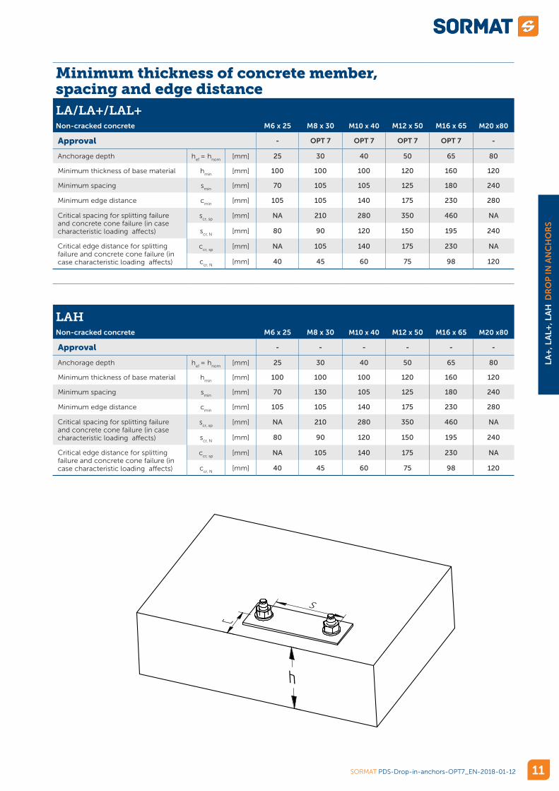
Minimum thickness of concrete member, spacing and edge distanceLA/LA+/LAL+Non-cracked concrete M6 x 25 M8 x 30 M10 x 40 M12 x 50 M16 x 65 M20 x80
Approval - OPT 7 OPT 7 OPT 7 OPT 7 -
Anchorage depth hef
= hnom
[mm] 25 30 40 50 65 80
Minimum thickness of base material hmin
[mm] 100 100 100 120 160 120
Minimum spacing smin
[mm] 70 105 105 125 180 240
Minimum edge distance cmin
[mm] 105 105 140 175 230 280
Critical spacing for splitting failure and concrete cone failure (in case characteristic loading affects)
scr, sp
[mm] NA 210 280 350 460 NA
scr, N
[mm] 80 90 120 150 195 240
Critical edge distance for splitting failure and concrete cone failure (in case characteristic loading affects)
ccr, sp
[mm] NA 105 140 175 230 NA
ccr, N
[mm] 40 45 60 75 98 120
LAHNon-cracked concrete M6 x 25 M8 x 30 M10 x 40 M12 x 50 M16 x 65 M20 x80
Approval - - - - - -
Anchorage depth hef
= hnom
[mm] 25 30 40 50 65 80
Minimum thickness of base material hmin
[mm] 100 100 100 120 160 120
Minimum spacing smin
[mm] 70 130 105 125 180 240
Minimum edge distance cmin
[mm] 105 105 140 175 230 280
Critical spacing for splitting failure and concrete cone failure (in case characteristic loading affects)
scr, sp
[mm] NA 210 280 350 460 NA
scr, N
[mm] 80 90 120 150 195 240
Critical edge distance for splitting failure and concrete cone failure (in case characteristic loading affects)
ccr, sp
[mm] NA 105 140 175 230 NA
ccr, N
[mm] 40 45 60 75 98 120REVISION HISTORY
REV DESCRIPTIONDate/By Approved by
SCALE
DRAWN
CHECKED
NAME
juhman
DATE
17.05.2017
TITLE
SIZE
A3
DRAWINGNUMBER REV
S-KA_TDS.dft
WEIGHT:
SHEET 1 OF 1
Co
pyrigh
t b
y S
orm
at O
y. A
ll rig
hts
re
se
rved
. R
efe
r to
pro
tection
notice I
SO
16
01
6.
1:2
0,000 kg
MATERIAL
GRADE Error: No reference Error: No referenceSTRENGTH
COATING Error: No reference Error: No reference
FILE NAME
REPLACES
THICKNESS > Error: No referenceSURFACE HARDNESS Error: No reference
Error: No reference
MAT. INFO1 Error: No referenceMAT. INFO2
ADD. INFO1 :
ADD. INFO2 :
Dimensionswithout tolerancein acc. with DIN
7168, middle
STANDARD
µm
SORMAT PDS-Drop-in-anchors-OPT7_EN-2018-01-12
LA
+, L
AL+
, LA
H D
RO
P IN
AN
CH
OR
S
11
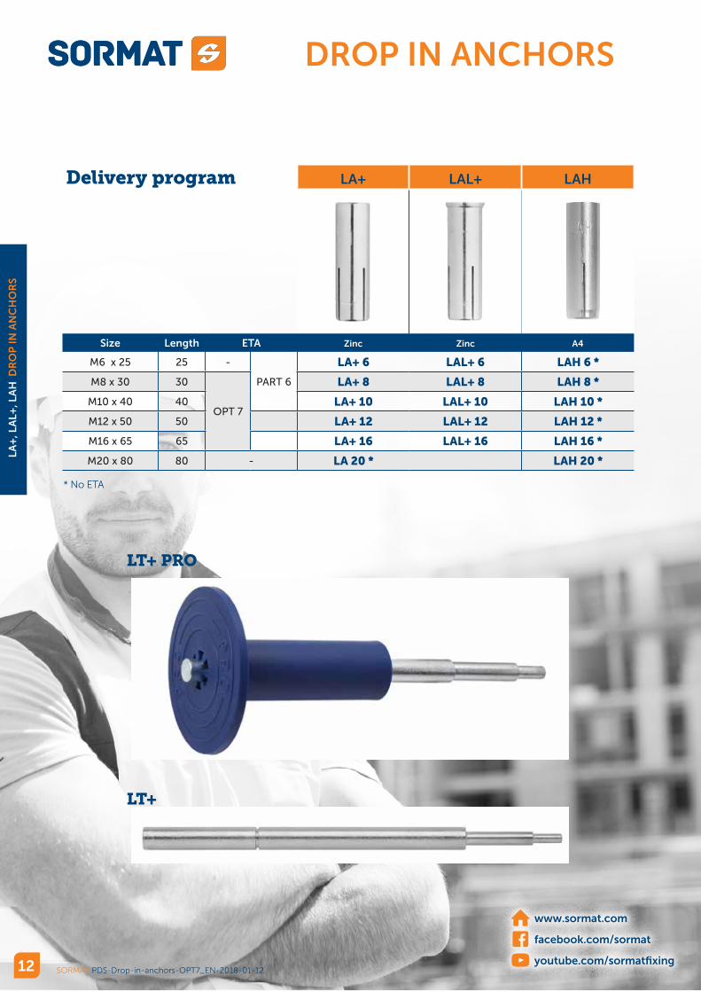
Delivery program LA+ LAL+ LAH
Size Length ETA Zinc Zinc A4
M6 x 25 25 -
PART 6
LA+ 6 LAL+ 6 LAH 6 *
M8 x 30 30
OPT 7
LA+ 8 LAL+ 8 LAH 8 *
M10 x 40 40 LA+ 10 LAL+ 10 LAH 10 *
M12 x 50 50 LA+ 12 LAL+ 12 LAH 12 *
M16 x 65 65 LA+ 16 LAL+ 16 LAH 16 *
M20 x 80 80 - LA 20 * LAH 20 *
LT+ PRO
LT+
SORMAT PDS-Drop-in-anchors-OPT7_EN-2018-01-12
LA
+, L
AL+
, LA
H D
RO
P IN
AN
CH
OR
S
12
www.sormat.com
facebook.com/sormat
youtube.com/sormatfixing
DROP IN ANCHORS
* No ETA


![Welcome! [info2.magento.com]info2.magento.com/.../newsletter-webinar-deck.pdf · 12/4/2012 23 Link Newsletter Articles Back to Your Store Create a Page Hierarchy with Navigation 1](https://img.pdfslide.us/doc/110x75/5f05749d7e708231d4130cd2/welcome-info2-info2-1242012-23-link-newsletter-articles-back-to-your-store.jpg)