Embed Size (px)
Citation preview
L7 : ENVIRONMENTAL LEGISLATION AND POLLUTION CONTROL IN CAST IRON FOUNDRIES
Ashimesh Dutt Scientist-in-Charge, RLC, National Metallurgical Laboratory, Calcutta.
INTRODUCTION
It is a time-old relationship between metal and man : iron is one such
metal in use. To meet various needs, iron is melted and cast into the desired
shapes; this phenomena has brought into the very existence of Cast Iron
Foundries. To melt iron, energy in the form of heat is provided through
combustion of carbon, the most techno-economic form of which is coke.
Besides heat, the other prcducts of this combustion, fine particulates of
ash, CO, SO., NO etc. are released to the atmosphere. In a small area, such
' as Howrah, about one million ton of CI Castings are made annually burning
300,000 tons of coke of which ash constitutes one third of its weight. In
t.lie proce:.,s, the ash gets converted partly into slag and remaining find its
place in the atmosphere in the form of solid particulate matter causing
environmental problem for the people and living objects in the vicinity of
these foundries. The cumulative effect of this practice for years has caused
an alarming situation compelling us to find out urgently most conducive
solution.
This problem is world-wide and has been considered by the guard-
ians of different Nations and various Environmental Preventive Acts (EPA)
have been formulated to prevent indiscriminate release of harmful mate-
rials to the environment. All such efforts in the developed world has
resulted better environmental conditions; but simultaneously boosted up
the cost of their products due to adoption of suitable pollution abatement
measures. According to Mr. NickThurston, Principal Pollution Control Officer,
L7-1
Walsall Borough Council, U.K. it would be prohibitively expensive for small
cold blast cupolas of below 4 tons per hour output to maintain emission
level as prescribed in EPA-90.
Our country is also not lagging much behind. Already Central
Pollution Control Board (CPCB) at Delhi through different State Agencies
is seriously looking at this problem since some time; legislations have been
made and some are in the process. State authorities are advised to be
vigilant and strictures are coming from the Supreme Court. To overcome
this state of affairs, it is high time to take an account of this problem under
Indian scenario and to find out some techno-economic solutions for the
foundries.
SOURCES OF POLLUTANTS IN CAST IRON FOUNDRIES
Depending on the character and size of the foundry, emission of
pollutants takes place. In a cast iron foundry the areas of emission may be
broadly classified as follows :
(1) Emission from the melting pot : Cupola
(ii) Emission from non-melting areas : raw material storage spaces,
sand preparation, mixing, moulding, core making, shake-out,
cleaning etc.
(iii) Emission from hot chamber
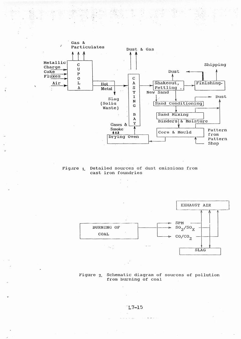
The schematic diagram of a typical Cl Foundry (Fig. 1) illustrate the
above.
L7-2
Emission from cupola
Cupola is a traditional melting pot in a cast iron (CI) foundry. It has
got a unique character to achieve the target at a minimum investment and
operational cost. Coke is the basic fuel to provide necessary thermal energy
to get the solid metallic charge melted and raised to a desired temperature
for proper casting. Coke, particularly of Indian origin, contains a very high
ash percentage. At Howrah mostly beehive coke is used. Here not only high
ash content (35-40%) is a troublesome phenomenon, but also inherent
volatile matters cause certain additional problems. To take care of the ash
content of coke, appropriate quantity of fluxing material :Ike limestone is
added to the charge to get the slag in proper fluid state. Fig-2 illustrates the
mechanism of the role played by ash during combustion of coke. In the
presence of adequate fluxing material, 1440°C is the softening temperature
of ash. Subsequent to the burning of coke in presence of oxygen available
in air, the released ash gets converted into slag above the temperature level
of 1440°C with the help of fluxing material like lime-stone, or solid
particulate matters (SPM) below the temperature level of 1440°C. Slag thus
produced in molten condition is drained out through the slag-spout while
(lie SI'M produced gets drifted upward alongwith the air-current through
the stack and finally escapes to the atmosphere through the tip of the
furnace. The size of this particulates being of the order of a few microns,
remain suspended in the air and cause adverse effect to the environment.
Sulphur content in coke gets oxidised as combustion takes place
and the product, SO2 and SO. joins the exhaust gas through the chimney.
However, as it has been observed that 50% of sulphur from coke gets
absorbed by the metal and most of the remaining get oxidised and go out
alongwith the exhaust gas, only a small portion goes to the slag.
L7-3
At the combustion zone of the cupola, carbon from coke is converted
moistly into carbon-dioxide and move upwards through the stack region. In
the process a part of it gets reacted with incoming charge coke liberating
carbon monoxide. This carbon monoxide alongwith unreacted carbon-
dioxide escapes the cupolas exhaust gas. Similarly Nitrogen-oxides, if
produced, also escapes alongwith the exhaust gas.
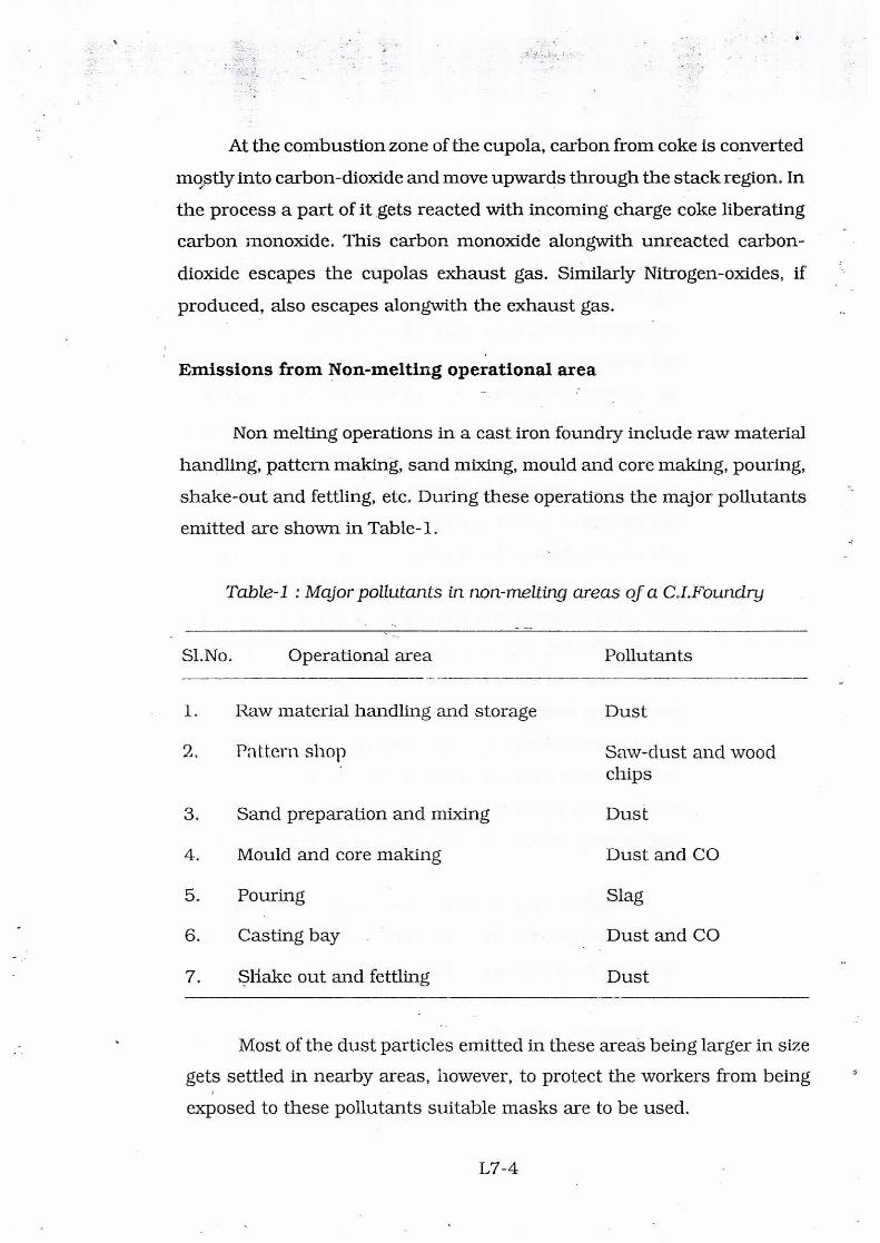
Emissions from Non-melting operational area
Non melting operations in a cast iron foundry include raw material
handling, pattern making, sand mixing, mould and core making, pouring,
shake-out and fettling, etc. During these operations the major pollutants
emitted are shown in Table-1.
Table-1 : Major pollutants in non-melting areas of a C.I.Foundry
Sl.No. Operational area Pollutants
1. Raw material handling and storage Dust
2. Pattern shop Saw-dust and wood chips
3. Sand preparation and mixing Dust
4. Mould and core making Dust and CO
5. Pouring Slag
6. Casting bay Dust and CO
7. Shake out and fettling Dust
Most of the dust particles emitted in these areas being larger in size
gets settled in nearby areas, however, to protect the workers from being
exposed to these pollutants suitable masks are to be used.
L7-4
Emission from Hot Chamber
All C.I. foundries are having hot-chambers of suitable size to dry cores
and moulds. These chambers are mostly heated by passing stream of hot air
evolved from burning coal. Depending on the design of the coal-burning system
pollutants like CO, CO2, SO2 and smoke are emitted.
LEGISLATION
In order to assess the extent of pollution in any area or at the vicinity of
any process plant, the first requirement is to design a standard against which
a pollution source should be compared. Around the world many such
standards have been designed to data keeping in view of the nature of industries
a country has and other relevant conditions applicable to that country. It may
be noted that even through these standards vary to some extent, there are lot
of similarities among them. Some of these standards have been designed by
such agencies as United States Environmental Protection Agency (USEPA),
standards designed by British Standard Institution, National Society for clean
air (U.K), and in India Central Pollution Control Board and the respective
Pollution Control Boards of each state, West Bengal Pollution Control Board,
In lite prtssent context..
As a typical example Table-2 gives the national ambient air quality
standards adopted by the united States EPA. Similarly the British Standards
BS 1747:19 provides the methods of measurement of air pollution. Similarly in
India Central Pollution Control Board publication "Pollution Control Act, Rules
and notifications issued therein", published in December 1992 provides major
guidelines with respect to the assessment and center of pollution from different
industries.
In similar lines for example West Bengal Pollution Central Board has
developed its own guidelines. The limits of emission for cupolas as designed by
L7-5
West Bengal Pollution Control Board is given in Table-3. It may be noted that
the CPCB designed separate norms for suspended particulate matters for
different sizes of cupola are different. On the contrary the British Standard
specifies the uniform emission limit of -115 mg/Nm3 for cupolas for all sizes.
Since there is no scientific logic for fixing different standards for different sizes
of cupola based on melting rate (not dia of cupola), this point requires to be
critically looked into. Another point that needs careful consideration is the most
appropriate sampling point. In some cases the sampling done at the charging
door and not at the stack exit. The character of stack air near charging door
is not necessarily be the same as it is released to the atmosphere from the
system. Hence it should be more appropriate to do the sampling at the stack
exit. Further, this allows sampling at any point of time during the operation, and
it is sensitive to changes in stack height.
CONTROL MEASURES
It is evident from the present practices, the emission released from C.I.
1UI1ndries 01111(lia general and of Howl-all in particular are much above the
desired level as prescribed by the Pollution Control authorities in India. This has
compelled the concerned industries for their survival lo look around for some
acceptable solutions. Cupola being the main source of emission violating the
pollution norms, require special attention.
The study reveals that liberation level of SPM and SO. are causing
problems ; other pollutants like CO and NOx are not in an alarming state. The
common source of all these pollutants is the process of coke combustion to
meet heat demand of the furnace i.e. cupola. Hence, more efficient is the
combustion process less is the requirement of coke resulting less evolution of
pollutants. Thus the pollution problem from cupola is to be dealt with in two
stages - (1) Making the cupola more fuel efficient, and (ii) arresting the pollutants
before the exhaust air is allowed to be released to the atmosphere.
L7-6
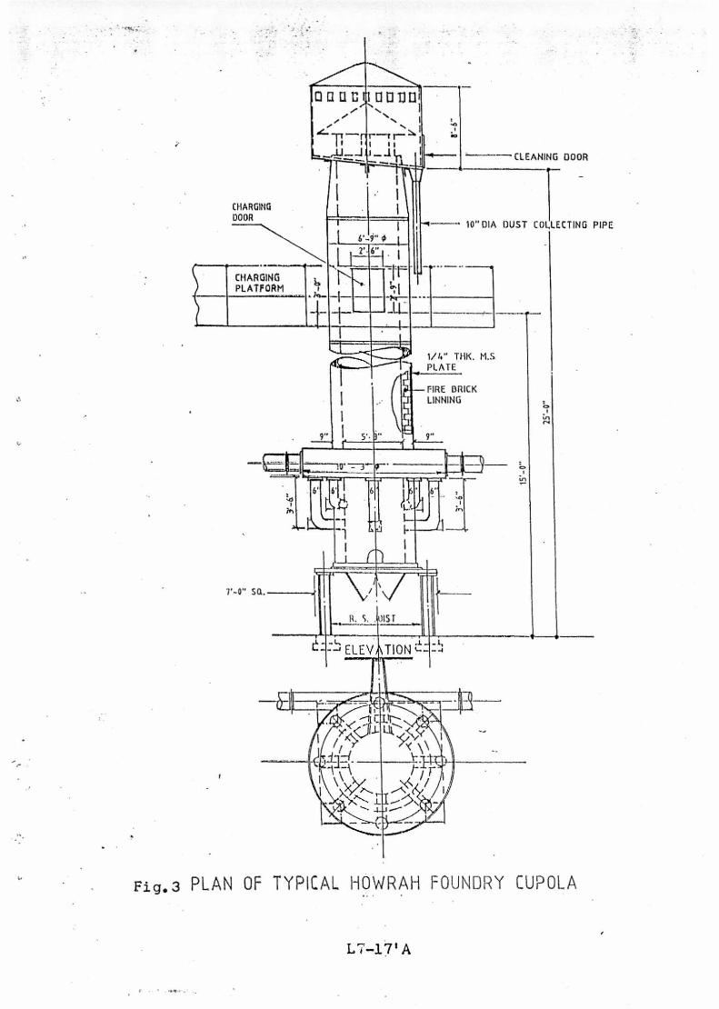
1. Fuel Efficient Cupola Operation
Most of the cupolas in Howrah do not satisfy the engineering needs
of dimensional proportions resulting in poor heat exchange, incomplete
combustion, etc. The following aspects are to be considered for remodeling
the cupola to make it a fuel efficient one
(i) Design Parameters :
Fig-3 presents line diagram of a typical cupola outlay in Howrah
foundries. Air is one of the most important component for combustion, its
availability both in adequate volume and pressure in the combustion zone is
essential for efficiency purpose. If the volume and/or pressure is more or less
than the actual requirement, it will effect the efficiency. This phenomenon
invites a thorough check in the entire system covering capacity of the blower,
air transporting, distribution through wind-belt and tuyere system and finally
the ratio between tuyere openings and area of combustion. Keeping in mind
about fuel efficiency, number of methodologies have been suggested for
adoption like divided blast, equi-blast, balanced blast etc. In each case the
conventional design to wind belt. and its distribution system is to be modified
suitably. Before selecting any, points relating to intending practice, ease of
operation, financial commitments, etc. are to be considered. Once this aspect
is settled, the tuyere openings in the cupola are to be suitably adjusted. It is a
common practice to have sets of tuyeres at two different levels having some
space in between, this space is to be maintained in view of widening of the
combustion zone. Since combustion of coke affects considerably with the ratio
between tuyere-opening area and cross-sectional area of the dia. of the cupola,
this factor is essential to be ascertained appropriately.
After combustion, the gaseous products travel upwards confronting with
the down coming solid charges, this area is normally termed as stack region and
L7-7
extends between charging door level to the melting zone. Here adequate heat
exchange should take place between the hot outgoing gases and the cold
incoming charges to pickup sufficient temperature before it reaches the
melting zone. Simultaneously CO2, the main product of coke combustion
during its travel through the stack region comes in contact with the charge
coke; depending on reactivity of the coke, gets partly converted into CO
through an endothermic reaction. So considering these two opposing
consequences, it has been accepted that the stack height should extend 5
to 6 times that of the cupola inner dia.
The portion above the charging door functions as chimney to give an
easy passage for the exhaust gases. This portion, according to the norms
laid down by the pollution authorities is to be extended 6 times that of the
dia. of the chimney.
(ii) Operational Practices
There are certain areas of apparently less importance where mere
ignorance causes high coke consumption. Cupola charges is one such
area. Very little attention is paid to the material size of coke and metallic
charges. It has been observed that metallic pieces weighing 60-80- Kgs are
charged in a cupola having inner diameter of the range of 36" to 40", Such
incidences reduces the metallic flow rate within the furnace due to
obstructions created at the melting zone. Similarly the charge coke of below
2" size becomes relatively more reactive due to their surface area compared
to their mass; this helps to increase the possibilities of more .endothermic
reactions between the outgoing CO2 and incoming carbon yielding CO. To _
overcome these problems, it has been prescribed to (a) reduce the size of
metallic charges before charging to the tune of 1 /8th to 1 / 12th of the I.D.
of cupola, and (b) to remove the coke pieces smaller than 2" in dia.
L7-8
(iii) Instrumentation
2
Practically all the.Howrah foundries are not having any instrumental
facilities to assess the entire process control system. Even the rudimentary
weighing scales are absent in some of the charging platforms; the charges are
generally estimated by number of bucket full materials charged. Most of the
foundries are not having any equipment to ascertain the volume of air getting
into the furnace and its pressure is almost unknown to the cupola operators.
All these induce a sort ofuncertainty about the combustion and heat flow taking
place within the furnace.
It is a bare necessity to be equipped with the instruments to provide data
on volume and pressure of the air going in, temperature of the molten metal
coming out, the actual weight of each charging materials going into in every
batch, as also a fair idea of the chemical analysis of the charging material.
All the points discussed above are to be taken into consideration as a
posi tive step for making a cupola fuel efficient, in other words, consumption of
coke minimised in terms of molten metal output of a cupola.
2. Pollution Abatement
Once emission has set in and the exhaust gas is contaminated with SPM,
SO2 and CO at a level much higher than the prescribed limits of Pollution
Control Authorities, some measures to arrest the pollutants are essential.
Depending upon, the sizes of the particulates and their weight
distribution in the exhaust gas, a separating device or combination of
devices maybe selected for use. In case of wide size distribution of particles,
it is desirable to separate coarser particles first involving equipment requiring
low capital and operating cost. This also avoids unnecessary loading of
L7-9
high-efficiency units capable of separating smaller sizes efficiently. Hence,
one has to choose, select and specify equipments according to the separa-
tion work required. The quantity of gases to be handled and their dust loads
are other important factors in the selection of equipment. Flow velocities
determine the pressure loss through the equipment. It is desirable that flow
velocities are kept low by a proper choice of equipment. The value of the
separated solids and required efficiency of their separation are sometimes
important considerations in the selection of equipment.
There is a wide list of separating devices working on principles for
arresting pollutants such as (i) gravitation, (ii) centrifugal force, (iii) internal
impaction, (iv) direct interaction, (v) diffusion, (vi) electro-static force, and
(vii) filtration. Following are commonly used collectors
Dry/Wet arrests
The simplest method of arresting grits is to attach a dry or wet
arrester to the cupola top. Since all the gases are drawn through the
arrester by stack drought alone, enough height and diameter should be
provided to make the arrester large enough to pass all the gases and air
infiltered through the charging door. Dry arresters are usually refractory
lined with the core unlined while the wet arresters are unlined and capable
of removing dust particles to the extent of 50%.
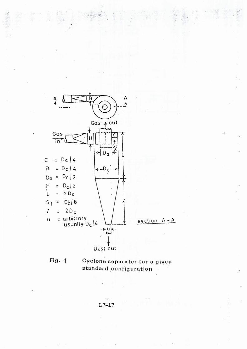
Cyclone type centrifugal collectors
Cyclone separators make use of centrifugal forces for arresting the
particles. In general, it consists of a cylindrical and a conical portion (Fig.4)
with a rectangular tangentical entry. As the gas enters, it spirals down-
wards in an outer vortex and comes out of the unit in an inner vortex. During
its stay in the unit the gas makes a given number of effective turns which is
L7-10
related to the efficiency expected. Cyclone separators are generally em-
ployed for separations following well accepted configurations depending on
the volume of the gas to be handled and the particle-separation efficiency
required.
The most striking aspect of cyclone separators is that they have no
moving parts. This makes them highly reliable, simple to construct and
least expensive of all high efficiency particle separators.
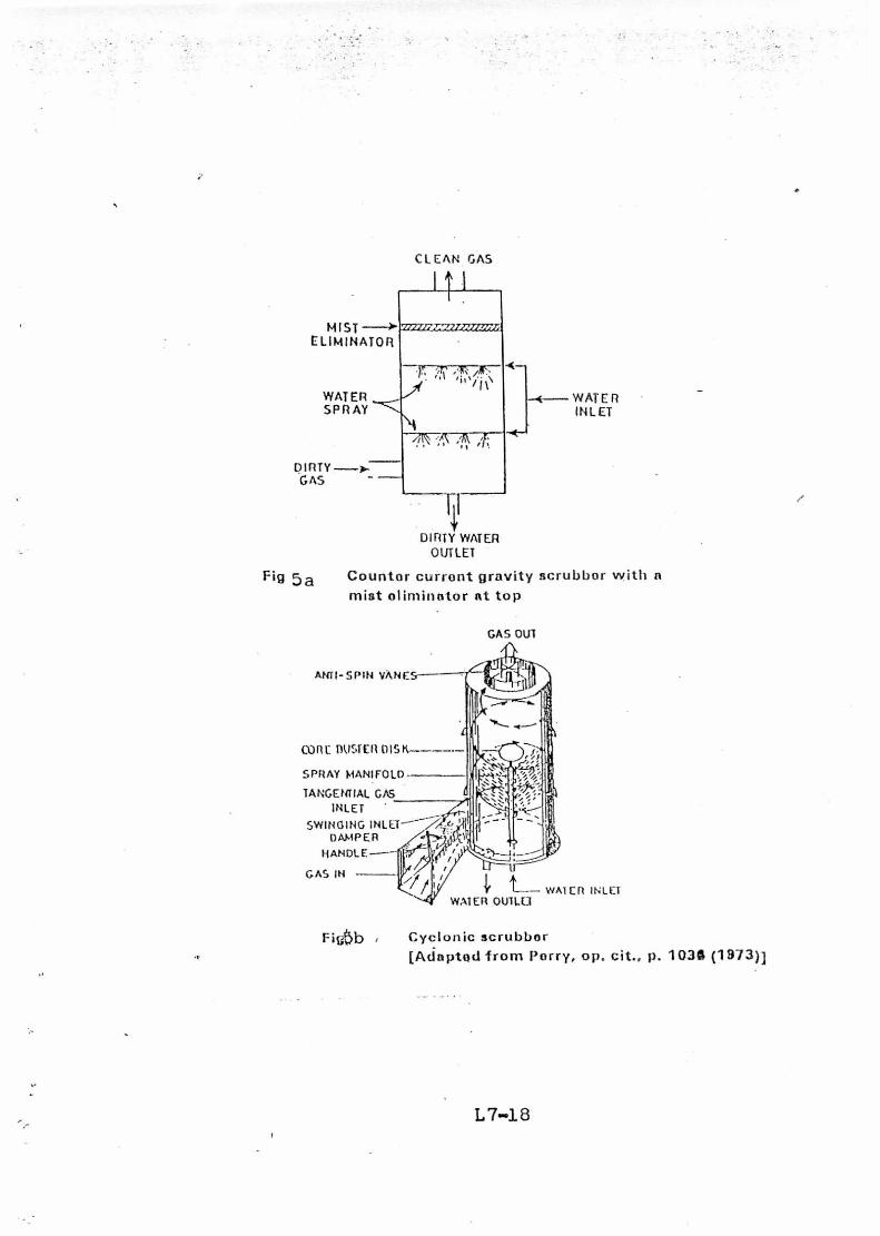
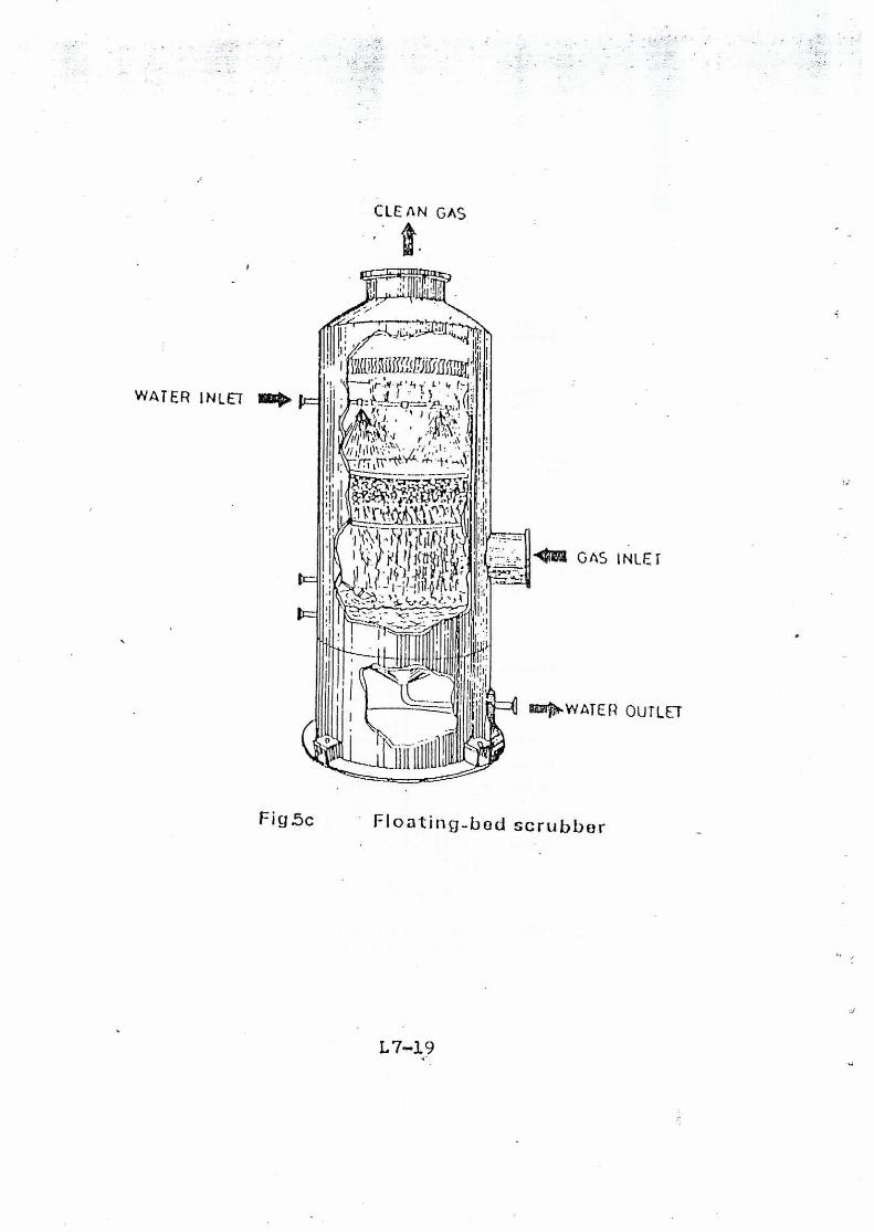
Wet CAP Collector/Low pressure scrubbers
In liquid scrubbers, the exhaust gas is brought in contact with a fine
spray of liquid, usually water. The separation of particles occurs essentially
by impaction, interception and diffusion, through humidification, conden-
sation; wetting and gravitation, all these phenomenon have their role to
play. There are a large variety ofwet collectors that have been commercialised.
Spray towers, packed towers, impingement scrubbers, cyclonic scrubbers
and floating-bed scrubbers are low energy units (Fig-5). The pressure loss
is between 2 and 15 cm of water but the efficiency of collection for low
particle size is limited. Particle size above 5 microns can be easily removed.
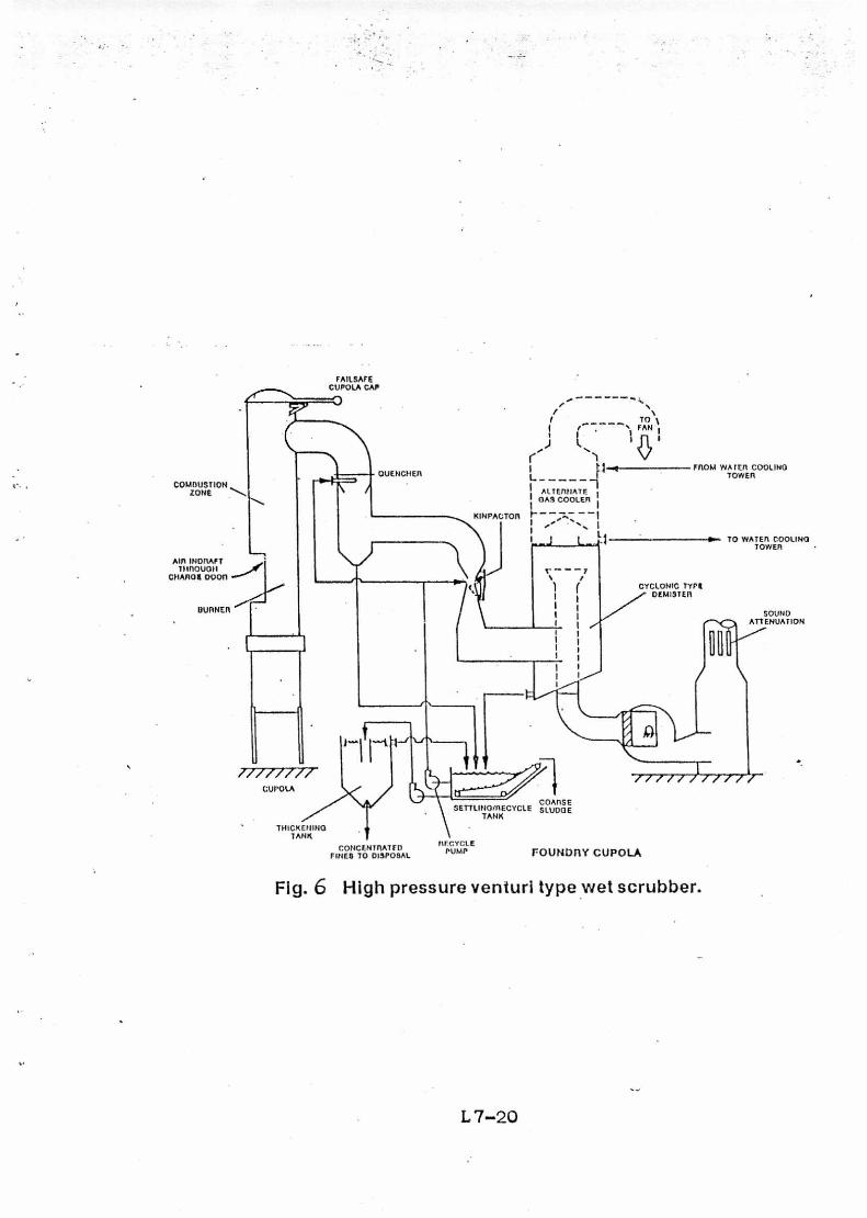
High pressure venturi type scrubber
Fig-6 illustrates a typical dust-scrubber system using a high energy
venturi scrubber. All wet collectors have a fractional efficiency character-
istics; that is, their cleaning efficiency varies directlywith the size of particle
being collected. In general, high efficiency collection of fine particles require
increased energy input, which will be reflected in higher collection pressure
loss. With the development of the high-energy venturi type collector, it has
become possible to collect submicron particulates, fumes and smoke with
high efficiency.
L7-11
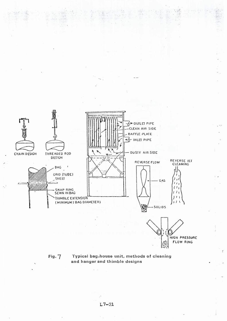
Baghouse filter system
The most of versatile equipment for removal of solid particulates from
the exhaust gas is the fabric dust collector (Fig-7). With a mass medium size
of 0.5micron, a collection efficiency of virtually 100 percent can be
expected. As the filter`media becomes dirty in a fabric collector, the higher
the efficiency of the unit becomes, and the finer the particles removed.
Filter media are now available for hot corrosive atmosphere such as
cupola emission yet the exhaust gas from cupola is always preferred to be
cooled down before allowing them to enter the bag-house filter system.
However, the cost of introduction of this system as also its operational cost
is very high and should be accounted for ascertaining the cost-benefit
analysis.
Electrostatic precipitators
Electrostatic precipitators work on the principle of charging the solid
particles suspended in air or gases by means of gas ions or electrons
produced by ionization of gases under a high energy electric field and
subsequent separation under the action of the field. Electrostatic precipi-
tators have a number of advantages over other separators. They are quite
flexible in operation with regard to gas-flow and dust loading variations.
The pressure-drop of gases in the unit is low and the efficiency very high
(average 98 to 99 percent), even for small particle size as low as 0.05
microns. The units can work upto gas temperature of 350°C, in SO2 and
moist atmospheres. They have a lower operating cost as compared to other
high efficiency gas-cleaning equipments. The cost of precipitators in-
creases for electrically-resistant particles. The chief disadvantage, how-
ever, is the high initial capital cost.
L7-12
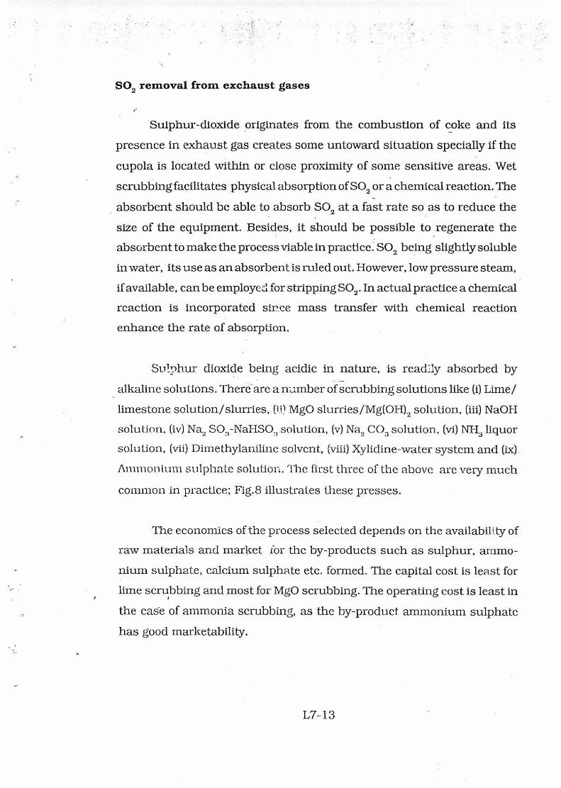
SO2 removal from exchaust gases
Sulphur-dioxide originates from the combustion of coke and its
presence in exhaust gas creates some untoward situation specially if the
cupola is located within or close proximity of some sensitive areas. Wet
scrubbing facilitates physical absorption of SO2 or a chemical reaction. The
absorbent should be able to absorb SO2 at a fast rate so a.s to reduce the
size of the equipment. Besides, it should be possible to regenerate the
absorbent to make the process viable in practice. SO2 being slightly soluble
in water, its use as an absorbent is ruled out. However, low pressure steam,
if available, can be employecl for stripping SO2. In actual practice a chemical
reaction is incorporated since mass transfer with chemical reaction
enhance the rate of absorption.
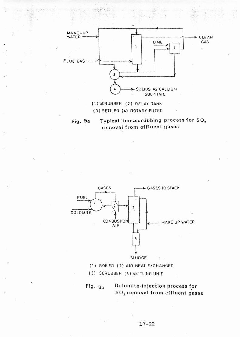
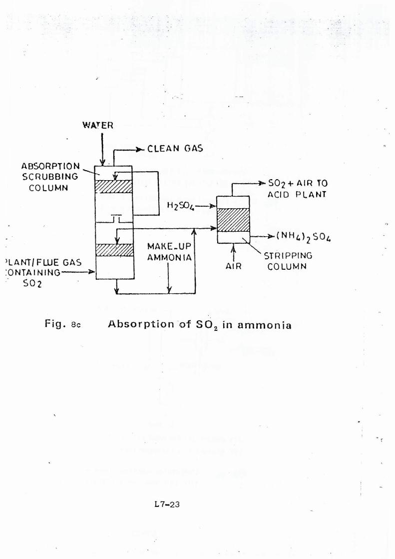
Sulphur dioxide being acidic in nature, is readily absorbed by
alkaline solutions. There are a number of scrubbing solutions like (1) Lime/
limestone solution/slurries, (U) MgO slurries/Mg(002 solution, (iii) NaOH
solution, (iv) Na, S03-NaHSO„ solution, (v) Na, CO, solution, (vi) NH3 liquor
solution, (vii) Dimethylaniline solvent, (viii) Xylidine-water system and (ix).
Ammon turn sulphate solution. The first three of the above are very much
common in practice; Fig.8 illustrates these presses.
The economics of the process selected depends on the availability of
raw materials and market for the by-products such as sulphur, ammo-
nium sulphate, calcium sulphate etc. formed. The capital cost is least for
lime scrubbing and most for MgO scrubbing. The operating cost is least in
the case of ammonia scrubbing, as the by-product ammonium sulphate
has good marketability.
L7-13
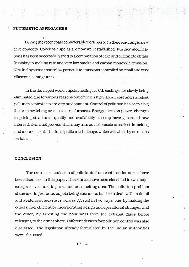
FUTURISTIC APPROACHES
During the recent past considerable work has been done resulting in new
developments. Cokeless cupolas are now well established. Further modifica-
tions has been successfully tried to a combination of coke and oil firing to obtain
flexibility in melting rate and very low smoke and carbon monoxide emission.
New fuel systems ensure low particulate emissions controlled by small and very
efficient cleaning units.
In the developed world cupola melting for C.I. castings are slowly being
eliminated due to various reasons out of which high labour cost and stringent
pollution control acts are very predominant. Control of pollution has been a big
factor in switching over to electric furnaces. Energy taxes on power, changes
in pricing structures, quality and availability of scrap have generated new
interest in lean fuel process which may turn out to be asclean as electric melting
and more efficient. This is a significant challenge, which will win is by no means
certain.
CONCLUSION
The sources of emission of pollutants from cast iron foundries have
been discussed in this paper. The sources have been classified in two major
categories viz. melting area and non-melting area. The pollution problem
of the melting zone i.e. cupola being enormous has been dealt with in detail
and ab‘atement measures were suggested in two ways, one by making the
cupola, fuel efficient by incorporating design and operational changes, and
the other, by arresting the pollutants from the exhaust gases before
releaqing to the atmosphere. Different devices for pollution control was also
discussed. The legislation already formulated by the Indian authorities
were focussed.
L7-14
Dust
Shipping
-mac o
Shakeout, Fettling
Finishing.
New Sand Dust
PP-
Core & Mould I Pattern from Pattern Shop
Gas & Particulates
Hot Metal
Slag (Solia Waste)
Gases ac Smoke
4L ['Trying Oven
Dust & Gas A
C A S T
N G
A Y
Metallic Charge Coke Fluxes
Air
Sand Mixing --]
Binders & Moisture
Figure 1. Detailed sources of dust emissions from cast iron foundries
BURNING OF
COAL
EXHAUST AIR
A A
SPM SO2/SOX
CO/CO2
L SLAG
Figure 2. Schematic diagram of sources of pollution from burning of coal
L7-15
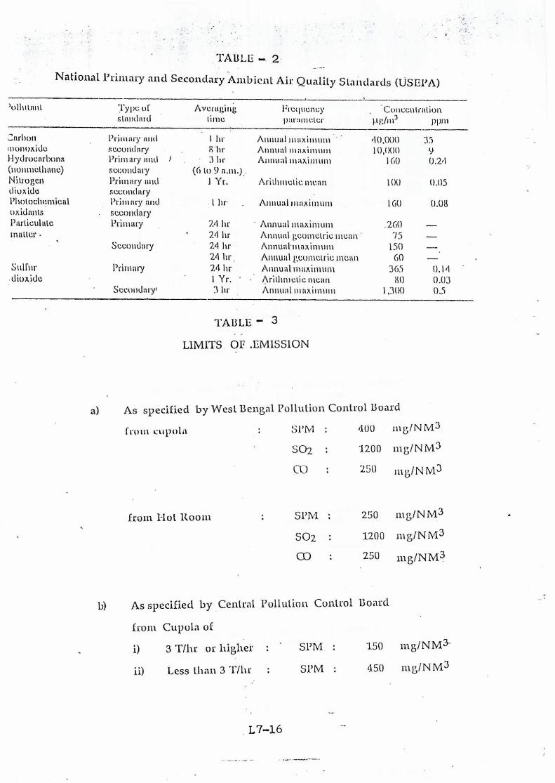
TABLE 2-
National Primary and Secondary Ambient Air Quality Standards (USEPA)
)olltnant
Type of Averaging Frequency
Concentration
standard time parameter
/-tg/m/ ppm
'Carbon
monoxide
Hydrocarbons
(nonmethane)
Primary and
secondary
Primary and
secondary
11w
8" hr
i • 3 hr
(6 to 9 a.m.):
Annual maximum
Annual maximum
Annual maximum
40,000
10,()00
160
35
9
0.24
Nitrogen
dioxide
Primary and
secondary
1 Yr. Arithmetic mean 1(X) 0.05
Photochemical
oxidants
Primary and
secondary
1 hr. Annual maximum 160 0.08
Particulate Primary 2.4 hr Annual maximum .260 -
matter • 24 hr Annual geometric mean . 75 _
Secondary 24 hr Annual- maximum 150
24 hr Annual geometric mean 60 -
Sulfur Primary 24 hr Annual maximum 365 0.14 -
dioxide 1 Yr. Arithmetic mean 80 0.03
Secondaty, 3 hr Annual maximum 1,300 05
TABLE 3
LIMITS OE .EMISSION
a) As specified by West Bengal Pollution Control Board
from cupola
from Hot Room
SPIVI : /100 m ON M3
S02 : 1200 rn g/N M3
CO : 250 mg/NM3
SPM : 250 mg/NM3
SO2 : 1200 mg/NM3
CO : 250 mg/NM3
As specified by Central Pollution Control Board
from Cupola of
1) 3 T/hr or higher
SPM : 150 mg/NM3-
ii) Less than 3 Tills . SPM : 450 mg/NM3
CHARGING DOOR
CHARGING PLATFORM
1
1 V
5'.
CLEANING DOOR
10" DIA DUST COLLECTING PIPE
1/I." MK. M.S PLATE
FIRE BRICK LINNING
•
Fig. 3 PLAN OF TYPICAL HOWRAH FOUNDRY CUPOLA
1,7-17'A
A 4
Gas out
Gas in
C r Dc 14
Dc/ 4
Da = Dc 12
H = Dc 12
1. 2 Dc
St = DC/8
2De
arbitrary usually OCR
sactiori A A
Dust out
Fig, 4 Cyclone soparator for as given standard configuration
L 7-17
WIC MISTER DISK--
SPRAY MANIFOLD
TANGENTIAL GAS
INLET SWINGING INLE1----7
DAMPER
HANDLE
t-- WAI ER INLET WATER MILLI
GAS IN
CLEAN GAS
WOO m
ELIMINATOR
WATER SPRAY
WATER INLET
4
GAS
Tl DIRTY WATER
OUTLET
Fig 5a Counter current gravity scrubber with a
mist eliminator at top
GAS OUT
Figbb , Cyclonic scrubbor
[Adapted from Perry, op. cit., p. 103$ (1973)]
CLEAN GAS
WATER INLET En*
•= GAS INLET
ENV* WATER OUTLET
Fig.5c Floating-bed scrubber
TO f • FAN
AL TErmATF. OAS COOLER
DUENCHET1 FROM WA rrn COOLING
TOWER COMRUSTION
ZONE
I- KINPACTOR
11.- TO WATER COOLING TOWER L.., L 1
AIR INCHIAFT ninouGli
CHARMS DOOR CYCLONIC rot
DEMISTER
BURNER SOUND ATTENUATION F,
-o
iQ 7/7/7//f
CUPOLA
SETTLING/RECYCLE COARSE TANK
SLUDGE
CONCENTRATED FINES TO DISPOSAL
RECYCLE PUMP FOUNUflY CUPOLA
THICKENING TANK
FAILSAFE CUPOLA CAP
Fig. 6 High pressure venturi type wet scrubber.
REVERSE JET CLEANING
t
t e
/ 1
) )
1 1
HIGH PRESSURE
rl* FLOW RING
CHAIN DESIGN THREADED ROD DES!GN
tai
GRID (TUBE) SHEET
SNAP RING SEWN IN DAG
THIMBLE EXTENSION
DAG
(MINIMUM I DAG DIAMETER)
-d_› OUTLET PIPE
--CLEAN AIR SIDE
BAFFLE PLATE
INLET PIPE
— DUSTY AIR SIDE
REVERSE FLOW
Fig. 7 Typical bag house unit, methods of cleaning and hanger and thimble designs
MAKE -UP WATER -11*
LIME
FLUE GAS
SOLIDS AS CALCIUM
SULPHATE
FUEL
DOLOMITE
COMBUSTION AIR
CLEAN GAS
(1) SCRUBBER ( 2 ) DELAY TANK
(3) SETTLER (4) ROTARY FILTER
Fig. 5a Typical lime-scrubbing process for SO2
removal from effluent gases
GASES 11-- GASES TO STACK
MAKE UP WATER
SLUDGE
(1) BOILER ( 2) AIR HEAT EXCHANGER
( 3') SCRUBBER (6) SETTLING UNIT
Fig. 8b
Dolomite-injection process for SO1 removal from effluent gases
AIR
MAKE_UP AMMONIA
SCRUBBING COLUMN rVY
H2594
„TT
'LAKTIFWE GAS 'ONTAINING
SO2
WATER
r CLEAN GAS
ABSORPTION 1- I
).
SO2 4- AIR TO ACID PLANT
(NH4)2 O4
STRIPPING COLUMN
Fig. 8c Absorption of SO2 in ammonia