Embed Size (px)
Citation preview
LEn RYC PY
lANGLEYRESEARCHCENTER
LIBRARY,NASA
]-IAMP__ON__)/IRGINI&
tl6/-61_l_tR]4I_l_dltS
II"_4_"_""_'-':'__:.•"!'!._.;_0,"
..,,,'-,_-__:,::'-__i-'J"aaup!oA%"du,,or
_alUlaa!meiI/aa!oqsn3_joffpmslenada:)uoD
_70_006L6
NASA Technical Memorandum 80141
Conceptual Study ofa Turbojet/Ramjet Inlet
John P. Weidner
Langley Research Center
Hampton, Virginia
NIIXNational Aeronautics
and Space Administration
Scientific and Technical
Information Branch
1979

SUMMARY
An inlet concept for separate turbojet and ramjet engines was defined and
compared with an equivalent inlet for a wraparound turboramjet engine. The com-
parison was made for a typical high-altitude hypersonic cruise vehicle where the
turbojet inlet capture area was required to be half as large as the ramjet inlet
capture area at cruise. Results of the study suggest the use of a shorter
nacelle having substantially lower cooling requirements at cruise for the inlet
concept for separate turbojet and ramjet engines. In addition, the separate
engine concept better isolates the turbojet from the ramjet, requires no special
close-off mechanisms within the turbojet, and avoids the circumferential heat
load imposed by a wraparound ramjet, but it does require more variable geometry.
INTRODUCTION
The first generation of manned hypersonic cruise vehicles will probably
utilize a ramjet propulsion system for high speeds and turbojets for subsonic
flight and low-speed acceleration. Studies conducted in the past two decades
(refs. ] and 2) have utilized such systems which typically employ a wraparound
turboramjet engine that is installed with a hypersonic inlet in much the same
manner as a turbojet engine is installed with a supersonic inlet. The turboram-
jet engine may be installed on the vehicle in a highly integrated fashion, as in
the airbreathing launch-vehicle studies of reference ] which utilize the vehicle
forebody for inlet precompression and the afterbody as part of the nozzle. How-
ever, for cruise applications at lower hypersonic speeds where the inlet and
nozzle do not become prohibitively large, the propulsion system may be installed
outside the forebody precompression region, such as on the wing, and will ingest
airflow at essentially free-stream conditions. The inlet design requirements
for a turbojet/ramjet propulsion system depend on the propulsion-system conceptas well as the usual mission-related factors. The relative location of the tur-
bojet and ramjet on the vehicle and their location to each other are important
factors. In the present report, both the wraparound turboramjet and separate
turbojet and ramjet concepts are considered.
The wraparound turboramjet is an integrated engine concept that consists
of a core turbojet inside an annular duct which forms the ramjet (ref. 3).
This results in a ramjet engine that has a large surface area. In addition,
the diameter at the engine face of the combined engine requires a large subsonic
diffuser ahead of the engine to meet the requirements of both the turbojet and
ramjet. Thus, the wraparound turboramjet engine leads to large, wetted, inter-
nal duct areas and heat loads at cruise, and because of its integrated nature,
may require the simultaneous development of both the turbojet and ramjet por-
tions of the engine. If independent propulsion nacelles were used to separate
the turbojet and ramjet engines, the development of the core turbojet and ramjet
could be done separately. However, a heavy propulsion system would result, as
would problems of locations for multiple nacelles on the vehicle. Past studies
have considered the possibility of using a common inlet to operate a separate
turbojet and ramjet or scramjet (refs. ] and 4), and they suggest certain advan-
tages for separating the two engines.
The purpose of this paper is to provide a baseline for studies and research
of the integration of vehicles and propulsion systems at low hypersonic speeds,
which is a concept similar to that of references ] and 4 for an inlet and dif-
fuser that would supply the necessary airflow for separate turbojet and ramjet
engines in the same nacelle. A comparison is made with a wraparound turboramjet
propulsion system installation using the same basic inlet design. The turbojet
and ramjet engines are sized for a typical high-altitude hypersonic cruise vehi-
cle operating at Mach 5. Some variation in relative engine-size requirements
was also considered to determine the impact on the propulsion nacelle.
It should be noted that there were many factors which were not specif-
ically assessed. These include the nozzle concept; nozzle performance; details
of engine cooling; ramjet f!ameholder effects on duct area; weight penalties;
and take-off, transonic, and off-design operational problems of the variable
geometry involved. In addition, the requirement for blow-in doors, boundary-
layer bleed, and other factors to facilitate inlet starting at supersonic speeds
has not been addressed. These factors will undoubtedly alter the performance
of a propulsion system. Further refinements of the design would necessarilyinvolve careful consideration of the factors mentioned.
SYMBOLS
Ac inlet cowl area
Ao inlet capture area
A t inlet throat area
Thrust
CT thrust coefficient,qAo
E engine face station
L/D vehicle lift-drag ratio
axial distance
M local Mach number
Mo free-stream Mach number
NS I station ahead of normal shock wave
NS 2 station behind normal shock wave
P2/PI local static-pressure ratio between two stations
P/Po ratio of local static pressure to free-stream static pressure
PT2/PTi local total-pressure ratio between two stations
PT/PTo ratio of local total pressure to free-stream total pressure
q free-stream dynamic pressure
t inlet throat station
t' inlet throat flow condition based on one-step calculation
TRJ wraparound turboramjet engine
TJ/RJ separate turbojet and ramjet engine
compressive-flow turning angle, deg
Prandtl-Meyer expansion angle, deg
ASSUMPTIONS
In order to define the geometric lines of a propulsion nacelle, values for
engine and airframe performance must be known, along with the flight require-
ments of the vehicle. The purpose of this paper is to present a concept for a
turboramjet inlet which may prove attractive for future hypersonic vehicle stud-
ies rather than to present the detailed design of a propulsion system to meet a
specific mission requirement. In this regard, the performance assumptions used
were based on current hypersonic aerodynamic research and on study engines that
are typical of what might be expected in future aircraft systems. Turbojet per-
formance is based on an advanced turbojet engine that has been studied for a
supersonic transport application and is described in reference 5. Typical ram-
jet performance is given in reference 3.
It is not the intention of this study to design an engine for a particular
mission, but rather to take these values as a typical case in order to develop
engine-inlet concepts and design considerations for hypersonic cruise vehicles.
PROPULSION REQUIREMENTS
The propulsion nacelle for a combined turbojet and ramjet engine must pro-
vide for the basic inlet requirements of both engines, In a turboramjet engine
designed for cruise applications, the turbojet is typically sized either by the
thrust required at take-off or by the aircraft drag at transonic speeds. In
addition, for a given turbojet size, the turbojet inlet cowl area is a strong
function of the maximumturbojet operating speed. Based on the performance
levels derived from reference 5 and the computed values of inlet efficiency,
operating the turbojet at Mach 3 would require a 60-percent larger inlet cowl
area than operating at Mach 2. Thus, the inlet cowl area required for the
turbojet is a function of both the thrust requirement of the vehicle and the
3
operating speed of the turbojet. For this study, a baseline turbojet inlet
area was chosen to correspond to a maximum operating speed of Mach 3.
In the selection of ramjet inlet area, cruise speed and altitude are
of primary importance. Since thrust is equal to drag at cruise, the inlet
area can be expressed as
Weight at cruise
Ac=qCT(L/D)
where weight at cruise is adjusted for centrifugal lift. As cruise speed is
increased, both CT and aerodynamic L/D are typically decreased, which tends
to increase ramjet inlet area. In addition, inlet area Js inversely propor-
tional to flight dynamic pressure q, which causes inlet area to increase with
increasing altitude. Thus, a large range of ramjet inlet sizes could be chosen
for a given size vehicle, with the dominant variables being speed and altitude.
For this study, a baseline ramjet inlet cowl area was chosen to correspond to a
cruise speed of Mach 5 at an altitude of 30 500 m.
An additional parameter to be determined in order to define the inlet-
engine propulsion nacelle is the ramjet burner size. The ramjet burner face
area used for this study was somewhat arbitrarily selected to be 0.4 of the
ramjet inlet cowl area. Based on calculated inlet compressive shock patterns,
this assumption yields a Mach number of 0.]] at the burner face at cruise
conditions.
INLET CONCEPT
In the previous section, propulsive performance requirements were somewhat
arbitrarily chosen and included cruise at Mach 5 at an altitude of 30 500 m and
a turbojet accelerator engine operating to a maximum speed of Mach 3. The
result of those assumptions is estimated to be a hypersonic propulsion system
having a turbojet inlet cowl area that is roughly 50 percent of the required
ramjet inlet cowl area. In addition, a moderate inlet contraction ratio Ac/A t
of 12 was used for the ramjet inlet at cruise to allow for a relatively high
level of inlet efficiency. The optimum selection of inlet contraction and the
proper allowances for boundary-layer bleed is a subject that requires detailed
tests and analysis, such as is given in reference 6, and is well beyond the
scope of this paper. These specific inlet and engine sizes are a strong func-
tion of the mission requirements imposed on the vehicle and represent only one
of the many combinations that could have been chosen.
Turboramjet Inlet Concepts
The turboramjet inlet and engines chosen for this study were integrated
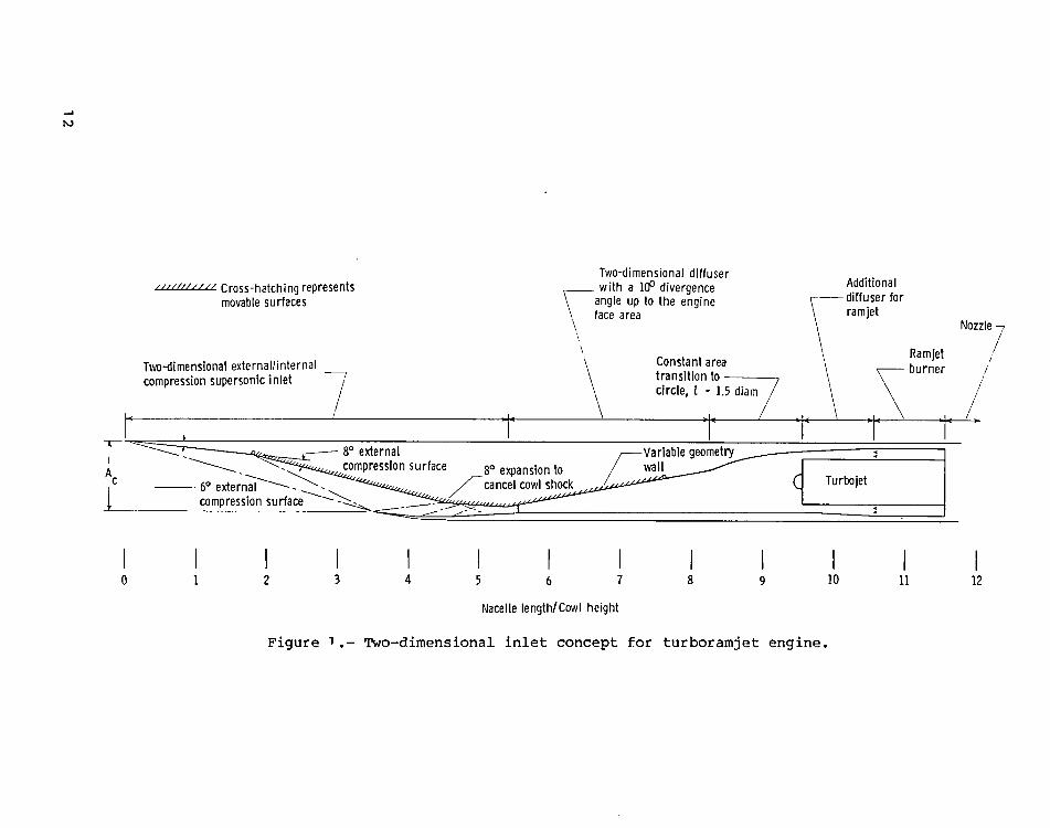
into a two-dimensional nacelle. A schematic of an inlet and subsonic diffuser
for a wraparound turboramjet engine is shown in figure I and represents a basis
4
of comparison for this study. The inlet is shown capturing free-stream airflow
at Mach 5 cruise conditions and has a contraction ratio of about 12. The two-
dimensional subsonic diffuser has a total expansion angle of 10 ° and extends
from the throat to a cross-sectional area equal to that of the total engine face
area. A constant-area transition section connects the rectangular diffuser to
the circular engine and is assumed to have a length equal to 1.5 times the total
turboramjet engine face diameter. An annular ramjet and a portion of its dif-
fuser are formed around the core turbojet and are aligned with the aft end of
the turbojet for installation to a nozzle. Variable geometry is accomplished by
a movable inlet upper wall (identified by the cross-hatching) which extends from
the second external compression surface to a point in the diffuser where the
cross-sectional area is somewhat greater than the maximum required inlet throat
area at transonic speeds.
The geometric lines of the turboramjet inlet and diffuser of figure ] are
considered to be generally representative of a Mach 5 engine system and yield
a relatively long nacelle to meet the demands of the wraparound turboramjet
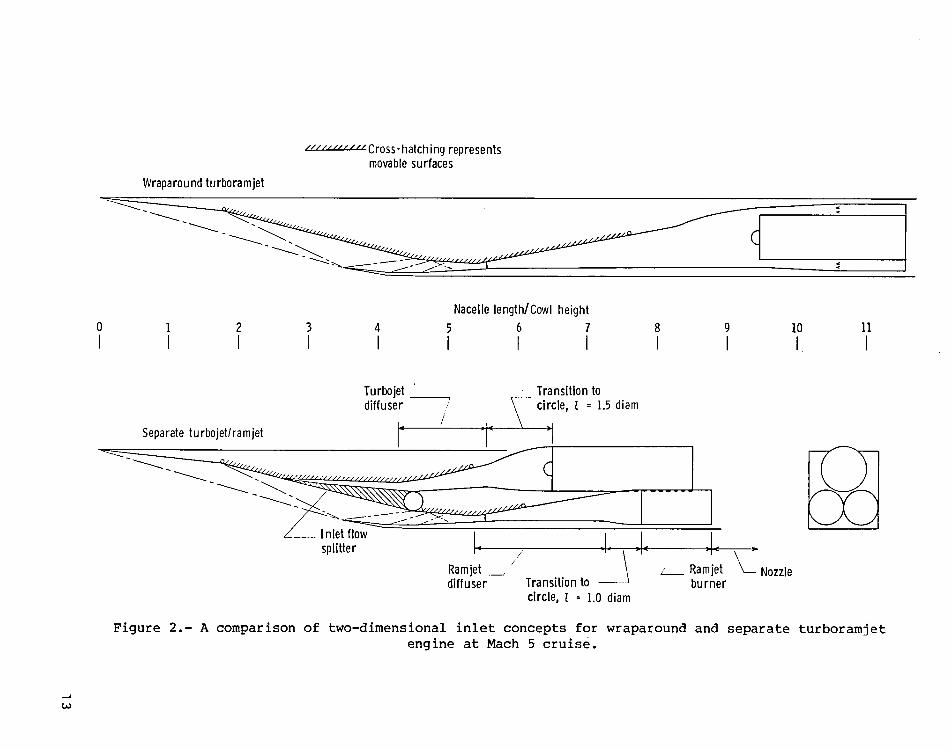
engine. An alternate approach is to separate the turbojet and ramjet enginesand their respective subsonic diffusers but to remain within the confines of a
single nacelle. A schematic of such an engine system is shown in figure 2 and
is compared with the same inlet system illustrated in figure I. The ramjet
inlet geometry at cruise is identical for the two cases shown. However, the
subsonic diffuser is only required to expand to a cross section equal to the
ramjet burner area and is followed by a shorter transition section since the
ramjet should be less sensitive to flow distortion than the turbojet. The
turbojet is accommodated above the ramjet burners by an inlet system that is
formed by opening the second external compression ramp of the ramjet inlet.
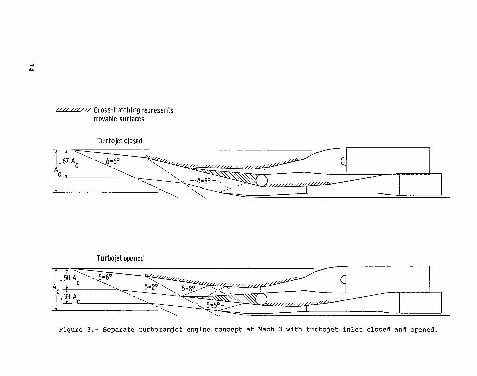
The lines of the inlet at Mach 3 during and after turbojet operation are shown
in the schematics of figure 3. The turbojet portion of the nacelle features
an external/internal compression inlet with its throat displaced forward of the
ramjet inlet throat and a short diffuser that is only required to expand the
airflow to a cross-sectional area equal to that of the turbojet face. The
result is a nacelle that is shorter by about 25 percent, than that required of
the wraparound turboramjet engine in figure 1. An additional benefit of the
separate engine inlet geometry is a reduced amount of external compressionwhen both engines are operating, which results in an increase in mass-flow
ratio from 67 percent to 83 percent of the inlet cowl area at Mach 3. This
improvement is caused by nearly eliminating the second external compression
surface when the turbojet inlet is opened. The nozzle has been omitted from
these nacelle schematics since its design, which includes weight, cooling,
thrust performance, and boattail drag considerations, is beyond the scope
of this paper. However, it might be observed that the separate engine concept
would lend itself to a two-dimensional type nozzle although the wraparound
turboramjet engine would integrate well with either axisymmetric or two-dimensional nozzles.
Inlet Analysis
The inlet design illustrated in figures I to 3 was intended to be a typi-
cal design for forming a basis of comparison between the separate and the wrap-
around ramjet engine approach. In this regard, inlet contours were defined to
yield an ideal compressive shock pattern at a design cruise speed of Mach 5.
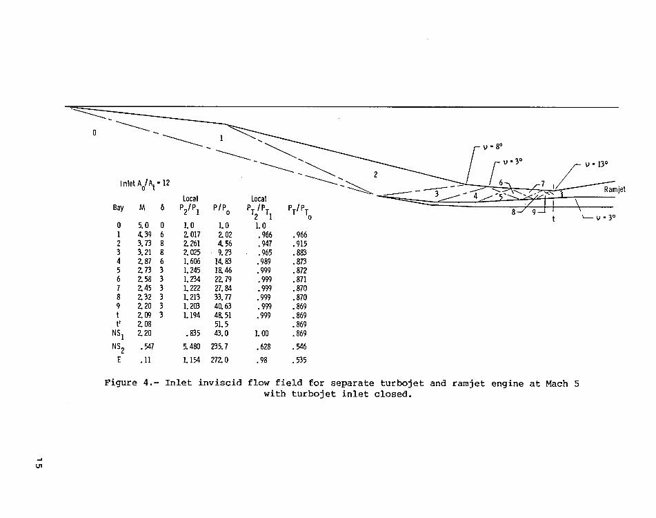
The inlet inviscid flow field is given in figure 4 and features two external
shock waves focused on the cowl lip. The internal shock wave originating from
the cowl lip is canceled by an expansion corner on the upper surface and is
followed by a second shock wave that is partially canceled by an expansion
corner on the upper surface. Beyond bay 4, compression is completed through a
series of weak shock waves, each having a compressive turning angle of 3° . The
result is an inlet having ]4° of external compressive turning and 32 ° of inter-
nal compressive turning.
The tabulation of inlet flow-field conditions given in figure 4 was derived
from the tables of reference 7 and includes Mach number, compressive turning
angle, both local static-pressure rise and total-pressure loss across the shock
wave ahead of a given bay, and the accumulated static-pressure rise and total-
pressure loss. Bay t' represents a one-step calculation using reference 8 todefine the inlet throat flow field based on an overall inlet contraction ratio
of 12 and the accumulated total pressure loss through the shock waves. In the
calculation of shock-wave loss, the normal shock wave is the major contributor
to the inlet total-pressure loss and is assumed to occur at a point beyond the
throat where the duct cross-sectional area has expanded I0 percent. Bays NS 1
and NS 2 represent the flow field ahead of and behind the normal shock wave.
The diffuser has a half-angle expansion of 5° , and based on reference 9, which
assumes a thin boundary layer, would have a total-pressure recovery of about
98 percent. The inlet flow field given in figure 4 represents only one of many
compression schedules and inlet contraction ratios which could be employed. A
final choice would be the result of trade-offs between performance, weight,
cost, and many other factors.
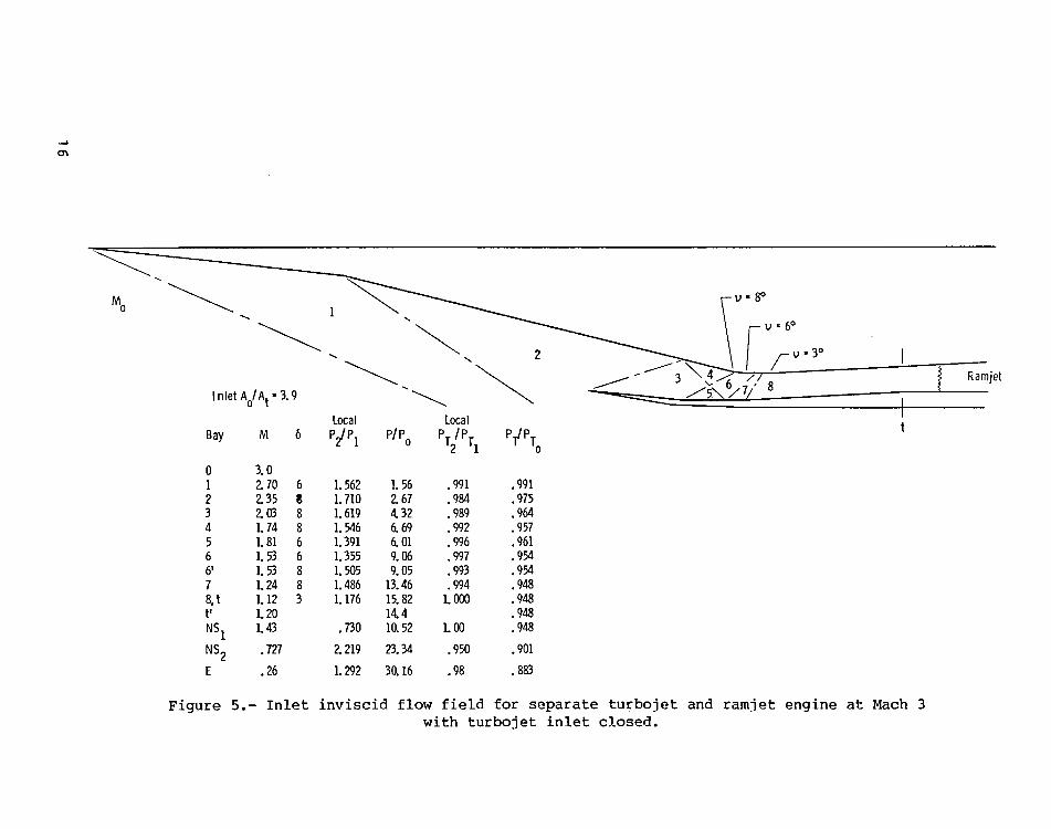
The inlet inviscid flow field at Mach 3, which corresponds to the inlet
geometries given in figure 3, is presented in figures 5 and 6. The inlet flow
field is given in figure 5 for the case in which the turbojet inlet is closed
and the internal variable-geometry wall is opened a maximum amount to reduce
the overall inlet contraction ratio. The resulting inlet aerodynamic contrac-
tion ratio Ao/A t is 3.9 and, along with a rapid compression schedule, producesa long constant-area throat section having a low supersonic Mach number. When
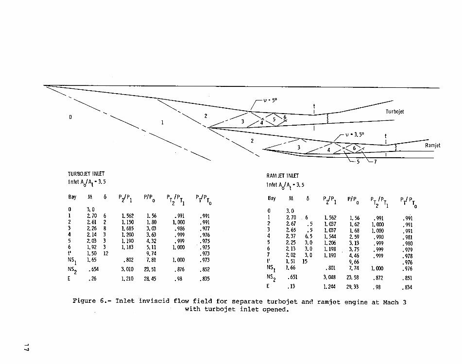
the turbojet inlet is opened, as illustrated in figure 6, the result is a flow
field with a reduced rate of compression within both inlets and weak shocks
ahead of the inlet throat. This flow field results from splitting the ingested
inlet airflow into two streams, each requiring a smaller throat area than the
combined flow field of figure 5.
The flow-field analyses given in figures 4 to 6 represent simplified cal-
culations based on inviscid flow assumptions and illustrate the types of flow
fields that could be encountered in these inlets. However, a transient condi-
tion will exist at M = 3 where the turbojet would be closing, with the total
airflow being shifted to the ramjet. This transient condition would have to be
analyzed based on the turbojet shutdown characteristics and the feasible rate
of change in geometry and fuel flows for the ramjet inlet portion. Experimental
results would be needed for the inlet configuration to address inlet performance
and unstart characteristics under those conditions. The inlet flow field for
the wraparound turboramjet engine at Mach 5 is identical to that given in fig-
ure 4 up to the normal shock, with the only difference being a larger subsonic
6
diffuser ahead of the engine. At Mach 3, the inlet flow field for the wrap-
around turboramjet engine would lie somewhere between that given in figures 5
and 6 for the separate turbojet/ramjet inlet concept.
Comparative Performance
Some of the differences between the separate and wraparound turbojet/ramjet
nacelle concepts include inlet mass-flow ratio at lower speeds, internal sur-
face area at cruise, and for the separate concept, a turbojet which is better
isolated from the ramjet. A detailed vehicle design and mission analysis would
be required to properly assess differences in propulsion-system performance on
overall vehicle performance. However, a cursory qualitative comparison of
the separate and wraparound turboramjet nacelle performance is given in thissection.
Inlet mass-flow ratio at speeds less than cruise can have an effect on
spillage drag, ramjet airflow, and the resulting acceleration performance.
Both of the inlet systems given in figure 2 are designed for full capture at
Mach 5. The mass-flow ratio of the inlet for separate engines is given at
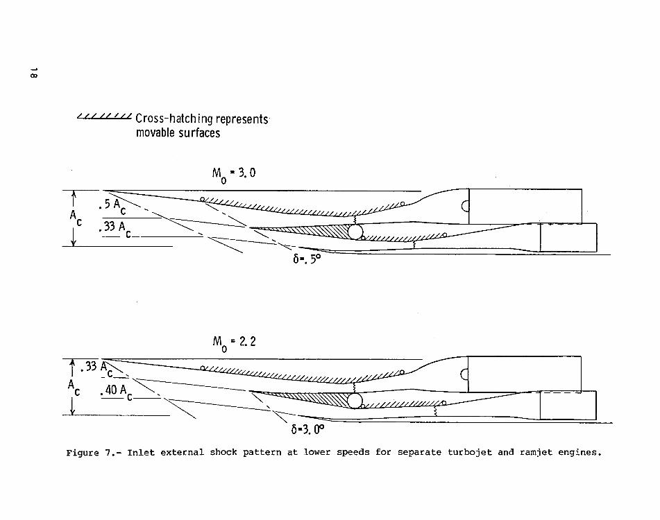
several lower Mach numbers in figures 3 and 7. Between Mach 5 and Mach 3,
the inlet spills across 14° of external compressive turning. At Mach 3, the
turbojet portion of the inlet is opened to provide the required airflow for
the turbojet, and consequently reduces the external inlet compression ahead
of the ramjet with a resulting increase in mass-flow ratio. At lower speeds
(fig. 7), the turbojet inlet closes to follow a required airflow schedule,whereas the inlet throat area is increased for a lower contraction ratio to
maintain supersonic flow at the inlet throat. The result is an increase in
external compressive turning ahead of the ramjet and an increase in inlet air
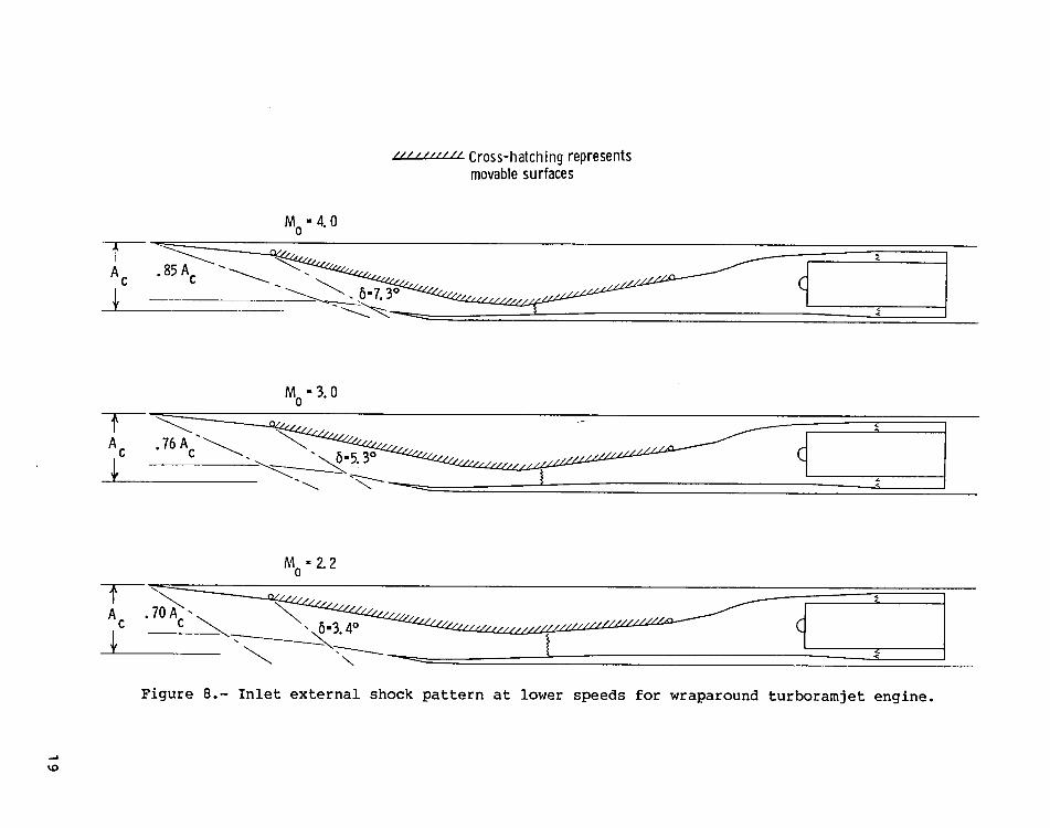
spilled at lower speeds. A set of inlet schematics illustrating spillage at
lower speeds for the wraparound turboramjet inlet is given in figure 8. For
this inlet, compressive turning across the second external compression surface
is reduced at lower Mach numbers as the inlet throat area is increased to pass
the combined ramjet and turbojet airflow at the proper contraction ratio.
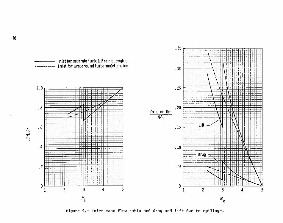
A summary of the mass-flow ratio of the two inlets derived from figures 3,
7, and 8 is compared in figure 9 in terms of mass-flow ratio plotted against
flight Mach number. The wraparound engine is given by the dashed curve and
shows some advantage in mass-flow ratio at speeds above Mach 3 and a reduced
mass-flow ratio below Mach 3. Additive drag resulting from the spillage airflow
is also given in figure 9 and shows the same trend, with a large percentage
increase in drag for the separate turbojet/ramjet inlet when the turbojet inletis closed. A large normal force also exists which would produce lift for an
inlet located on the bottom portion of an airframe and would be added to theairframe lift as was illustrated in reference ]0.
Important aspects of engine performance are weight and heat load at cruise,
both of which are a function of the internal surface area. A comparison of the
inlet, diffuser, and ramjet burner wetted areas for the wraparound and separate
engine concepts is given in table I. There is a small advantage for the sepa-
rate engine concept in terms of total wetted area, with the reduced wetted area
occurring in the inlet diffusers and ramjet burner. However, a much larger dif-
7
ference in surface area exposed to the engine airflow exists at higher speeds
when the turbojet is closed off, as shown in column 3 of table I. At this con _
dition, the inlet surface area up to the throat is the same, whereas the ramjet
diffuser and burner of the separate engine concept has only 45 percent of the
wetted surface area of the wraparound engine concept. The total surface area
that is exposed to the flow at cruise is thus reduced by 38 percent. The high-
est pressures occur in the ramjet diffuser and burner so that a significant
reduction in engine heat load would be expected for the separate engine concept.
For the separate engine concept, two circular ramjet burners were chosen in
response to the possibility of high pressure loads and the need for structural
efficiency. A single rectangular or elliptical combustor would further reduce
internal surface area by reducing or eliminating the ramjet diffuser transition
section and by reducing the surface area of the ramjet burner. The optimum
design requires a careful trade between structural efficiency and surface area
based on a particular mission. For this study, it was felt that circular ram-
jet combustors would represent a conservative comparison between the length and
wetted area of the two nacelle concepts. The weight of both the variable-
geometry wall sections and the required actuators for both concepts needs fur-
ther study to allow the proper trade-offs to be made.
In addition to the inlet mass-flow ratio, nacelle-size, and internal
surface-area differences between the engine concepts discussed so far, there
are additional aspects of the nacelle design which would influence performance.
One advantage of the separate engine concept is better isolation of the turbo-
jet from the ramjet. The turbojet is aerodynamically isolated from the ramjet
through the supersonic inlet, may not require special close-off doors, is not
circumferentially exposed to the ramjet heat load at cruise (as is the case
with the wraparound engine), and thus should allow more opportunity to utilize
existing turbojet engines. Potential disadvantages of the separate engine con-
cept might include the requirement for a more complicated nozzle and more exten-
sive use of variable geometry in the inlet.
Effect of Turbojet Engine Size and Transition Mach Number
on the Inlet Size
Thus far, the wraparound and separate tur boramjet engine nacelles were
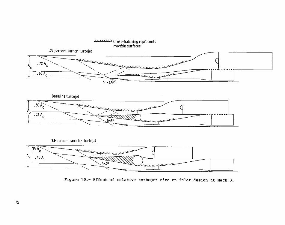
compared for the baseline turboramjet engine. The effect of changing the rela-
tive size of the turbojet and ramjet engines is parametrically illustrated in
figure ]0 in terms of three different size turbojets installed with the base-
line inlet and ramjet, which represent turbojets that are 43-percent larger and
34-percent smaller than the baseline turbojet size. As would be expected, a
change in turbojet size causes a corresponding change in the size of the tur-
bojet inlet and diffuser although the ramjet inlet and diffuser is unchanged
above Mach 3. As a result of larger turbojet installations, the forward mov-
able splitter becomes very thin, the structural depth above the ramjet variable-
geometry wall is limited, and expansion waves are formed ahead of the ramjet
inlet cowl, thus reducing its compressive performance. A similar effect can
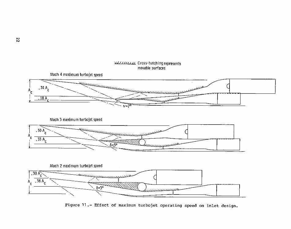
be seen in figure I], in which the engine nacelles are shown with the baseline
turbojet engine size but operating to different maximum speeds. In order to
properly match the turbojet demand airflow, the turbojet inlet size increases
slgnificantly at higher speeds and can domJnate the overall _nlet geometry.
The result at Mach 4 is a long turboiet inlet dominating the nacelle with little
a_rf!ow through the ramjet. Some of these inlet matching problems could prob-
ably be reduced by changing design features of the inlet. However, figures I0
and ]] do illustrate that there is a practical limit to the size of turbojet
inlet that can be accommodated within this separate turboramjet engine nacelle
concept.
CONCLUDING REMARKS
A study of an inlet concept for separate turbojet/ramjet engines for
hypersonic cruise vehicles has been conducted and has been compared with an
inlet concept for a wraparound turboramjet engine. Results of this studyindicate that
I. A nacelle for separate turbojet and ramjet engines can be defined,
with the turbojet portion of the inlet formed by opening the second external
compression surface of a basic two-dimensional ramjet inlet. The result was
a turbojet which did not require special close-off provisions and which was
better isolated from the ramjet heat load at hypersonic speeds.
2. Including the ramjet burner, the independent inlets and diffusers of
the separate engine concept resulted in a 25-percent shorter nacelle havJng
about 40 percent less surface area for cooling at cruise, as compared with a
wraparound turboramjet engine.
3. The concept of forming separate inlets with diffusers from an external
compression surface of a basic two-dimensional inlet becomes impractical for
separate turbojet and ramjet engines when the turboSet inlet size approaches
the size of the ramjet cruise inlet.
Langley Research Center
National Aeronautics and Space Administration
Hampton, VA 23665
August 15, 1979
9
REFERENCES
1. Morris, R. E.; and Williams, N. B.: Study of Air Breathing Launch Vehicles
With Cruise Capability. Volume Ill - Aerodynamics, Propulsion, and Sub-
systems. NASA CR-73196, ]968.
2. Jarlett, Frank E.: Performance Potential of Hydrogen-Fueled, Air-
breathing Cruise Aircraft - Final Report. Volume ] - Summary.
Rep. No. GD/C-DCB66-004/] (Contract NAS2-3180), General Dynamics,
Convair Div., Sept. 30, ]966. (Available as NASA CR-80499.)
3. Apel, G. F.; and Hines, R.W.: Estimated Performance of a Mach 8.0
Hydrogen Fueled Wrap-Around Turboramjet (SWAT-201B). TDM-2001
(Contract AF33 (615)-5153), Pratt & Whitney Aircraft, Jan. 4, 1967.
4. Gregory, T. J.; Williams, L. J.; and Wilcox, D. E.: Airbreathing Launch
Vehicle for Earth Orbit Shuttle - Performance and Operation. J. Aircr.,
vol. 8, no. 9, Sept. ]97], pp. 724-731.
5. Baber, Hal T., Jr.; and Swanson, E. E.: Advanced Supersonic Technology
Concept AST-]00 Characteristics Developed Jn a Baseline-Update Study.
NASA TM X-72815, ]976.
6. Latham, Elden A.; Sorensen, Norman E.; and Smeltzer, Donald B.: Investi-
gation of a Mixed Compression Axisymmetric Inlet at Mach Number 5.3.
NASA TN D-6647, 1972.
7. Dennard, John S.; and Spencer, Patricia B.: Ideal-Gas Tables for Oblique-
Shock Flow Parameters in Air at Mach Numbers From 1.05 to 12.0. NASA
TN D-2221, 1964.
8. Ames Research Staff: Equations, Tables, and Charts for Compressible Flow.
NACA Rep. 1135, 1953. (Supersedes NACA TN ]428.)
9. Internal Aerodynamics Manual. NR68H-434 (Contract NOw66-0460-d), Vol. I,
Columbus Div., North American Rockwell Corp., June 1970. (Available from
DDC as AD 723 823.)
10. Small, William J.; Weidner, John P.; and Johnston, P. J.: Scramjet Nozzle
Design and Analysis as Applied to a Highly Integrated Hypersonic Research
Airplane. NASA TN D-8334, ]976.
I0
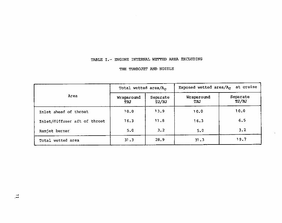
TABLE I.- ENGINE INTERNAL WETTED AREA EXCLUDING
THE TURBOJET AND NOZZLE
Total wetted area/A c Exposed wetted area/A c at cruise
Area Wraparound Separate Wraparound SeparateTPJ T_I_ TPJ TJI_
Inlet ahead of throat 10.0 13.9 I0.0 I0.0
Inlet/diffuser aft of throat 16.3 II.8 ]6.3 6.5
Ramjet burner 5.0 3.2 5.0 3.2
Total wetted area 31.3 28.9 31.3 19.7
-,,,l
Two-dimensionaldiffuser
,',,////-'/,'/Cross-hatching represents __ with a ]0° divergence Additionalmovablesurfaces _ angle up to the engine T-- diffuser for
\
face area _ ramjet
.\ Nozzle/\ Ramjet /
Two-dimensionalexternal/internal _. \ Constantarea _- burner /
/ transition=to _ ._ /
compressionsupersonicinlet circle, [ ]. /
, \ /< 14 - - _1. .I .I. / :_, T 1 T T
_c __ _ 8° external ,----Variable geometry _6° extern_._..__.. Scancel cowlshock . /_._._l.x-._--- Turbojet
compression surface___..____. ,1- --
I I I I I I I I I I I I I0 1 2 3 4 5 6 7 8 9 ]0 11 12
Nacellelength/Cowl height
Figure I .- Two-dimensional inlet concept for turboramjet engine.
/_'//"//////Cross- hatchingrepresentsmovablesurfaces
Wraparoundturboramjet
-__.
Nacellelength/Cowlheight0 1 2 3 4 5 6 7 8 9 lO II
I i i I I i i i i i i I
Turbojet __ __ Transitiontodiffuser .7 _ circle, [ - 1.5 diem
/ \Separateturbojet/ramjet " '1_ '_
_ _ "'_ / _ ........
/_ Inlet flow I , J- J/ Ramjet NozzleRamjet .' /
diffuser Transition to burnercircle, [ - 1.0 diem
Figure 2.- A comparison of two-dimensional inlet concepts for wraparound and separate turboramjetengine at Mach 5 cruise.
..J
.,.i
////////H Cross-hatchingrepresentsmovablesurfaces
Turbojetclosed
A -1
c J, _...\ _ _ t _ ......
Turbojetopened
L_ --___ _ -]Figure 3.- Separate turboramjet engine concept at Maeh 3 with turbojet inlet closed and opened.
Inlet Ao/At" 12 "__jet--.._
Local Local _ _ _-_ _' "_ ./ | j \Bay M 6 P2/PI P/Po PT/PT 1 PT/PT 8-./ 9 ---1 30o t U--u=0 5.0 0 l,O 1.0 l.O1 4.39 6 2.017 2_.02 ,966 9662 3.73 8 2.261 4. 56 ,947 9153 3,21 8 2.025 9. 23 ,965 8834 2.87 6 1.606 14.83 .989 8735 2.73 3 I. 245 l& 46 .999 8726 2.58 3 I.234 22.79 .999 8717 2.45 3 1.222 27.84 .999 8708 2.32 3 I. 213 33.77 .999 8709 2.20 3 1.203 40.63 .999 869t 2.09 3 I.194 4& 51 .999 869t' 2.08 51.5 869
NS1 2.20 .835 43.0 l.O0 869
NS2 .547 5.480 235.7 .628 .546E .II I.154 272.0 .98 .535
Figure 4.- Inlet inviscid flow field for separate turbojet and ramjet engine at Mach 5
with turbojet inlet closed.
_J
_n
-.i
0"_
Mo -v.86°
v'3° I
ILocal Local
B_y M 6 PgPIP/PoPT_/PTIP_PTo t0 3.01 2,70 6 1.562 1.56 .991 9912 2,35 8 1.710 2.67 .984 9753 2.03 8 1.619 4.32 .989 ,9644 1.74 8 1.546 6.69 .992 9575 1.81 6 1.391 6.O1 .996 9616 1.53 6 1.355 9.06 .997 9546' I. 53 8 I. 505 9. 05 .993 ,9.547 I.24 8 I.486 13.46 .994 948
8,t 1.12 3 1.176 15.82 1. 000 948t' I.20 14.4 948
NSI 1.43 .730 10.52 1.00 948
NS2 .727 2.219 23.34 .950 .901E .26 I.292 30.16 .98 .883
Figure 5.- Inlet inviscid flow field for separate turbojet and ramjet engine at Mach 3
with turbojet inlet closed.
0 "_ 1 _ 2 _ _/_'_6 I Turbojet
j_ _,:_< I _ Ramjet
"_ '_k---5 _--- 7
TURBOJETINLET RAMJETINLET
Inlet Ao/At - 3. 5 Inlet Ao/At - 3. 5
Bay M 8 P2/PI P/Po PT/PT1 Pl,/PTo Bay M 8 P2/PI P/Po PT2/PT1 Pl"/PTo
0 3.0 0 3.01 2. 70 6 1.562 1.56 .991 .991 1 2.70 6 1.562 I. 56 .991 9912 2.61 2 1.150 1.80 1.000 .991 2 2.67 .5 1.037 1.62 1.000 9913 2.26 8 1.685 3. 03 .986 .977 3 2.65 .5 1.037 1.68 1.000 9914 2. 14 3 1.200 3. 63 .999 .976 4 2.37 6.5 1.544 2.59 .990 9815 2. 03 3 1. 190 4.32 .999 .975 5 2.25 3. 0 1.206 3. 13 .999 9806 1.92 3 1. 183 5.11 I. 000 .975 6 2.13 3. 0 1.198 3. 75 .999 979t' I.50 12 9.74 .973 7 2.02 3.0 I.190 4.46 .999 978
NS1 1.65 .802 7.81 1.000 .973 t' 1.51 15 9,66 976
NS2 .654 3.010 23.51 .876 .852 NS1 1.66 .801 7.74 1.000 976E .26 1. 210 28.45 .98 .835 NS2 .651 3. 048 23.58 .872 .851
E .13 I.244 29.33 .98 .834
Figure 6.- Inlet inviscid flow field for separate turbojet and ramjet engine at Mach 3with turbojet inlet opened.
..a
-4
oo
Cross-hatchingrepresentsmovablesurfaces
M° - 3.0 _ ...___Ac ___ _
8".5°
-_ _ _ ____. (3/////////// /_--_Ac . i--- .-
Figure7.- Inlet external shock pattern at lower speeds for separate turbojet and ramjet engines.
///'/"///Cross-hatching representsmovablesurfaces
M -4.00
c " _ 6-z3°
M -3.00
Ac " c ._ -_6.5.3 o ........
Mo "2.2
Figure 8.- Inlet external shock pattern at lower speeds for wraparound turboramjet engine.
tOO
.35 . ; ...... _q-_: ! _t''':'T ',1
Inlet for separateturbojet/ramjetengine
........... Inlet for wraparound turboramjet engine .30
1.0 .25
.8 .20Dragor lift
qAc
.6 .15Ao
Ac
.4 .I0
.2 ..... .05i-
0 _--__l 0I 2 3 4 5 1 2 3 4 5
M M0 0
Figure 9,- Inlet mass flow ratio and drag and lift due to spillage.
/,,,H/H,'-, Cross-hatchingrepresentsmovablesurfaces
z13-percentlarger turbojet
Baselineturbojet
A "_'" . .j ...><. L. L_------- ' '
34-percentsmaller turbojet
c 45A_ _. _-"-_\\\\\\\\\\",.._ ] ,...._
Figure 10.- Effect of relative turbojet,size on inlet design at Mach 3.
:///////,// Cross-hatching representsmovablesurfaces
Math 4 maximum turbojet speed
Mach 3 maximum turbojet speed
I c
Mach 2 maximumturbojet speed
f.,o,_.... ,_,_Jf-A I
Figure II.- Effect of maximum turbojet operating speed on inlet design.


1. Report No. 2. Government AccessionNo. 3. Recipient's Catalog No.NASA TM-801 41
4. Title and Subtitle 5. Report DateSeptember ] 979
CONCEPTUAL STUDY OF A TURBOJET/RAMJET INLET6. Performing OrganizationCode
7. Author(s) 8. PerformingOrganization Report No.
John P. Weidner L-I 303610. Work Unit No.
9. PerformingOrganizationName and Address 505-] 1 -33-01
NASA Langley Research Center II. Contractor GrantNoHampton, VA 23665
13. Type of Report and Period Covered
12. SponsoringAgency Name and Address Technical Memorandum
National Aeronautics and Space Administration
Washington, DC 20546 14. SponsoringAgency Code
15. Supplementary Notes
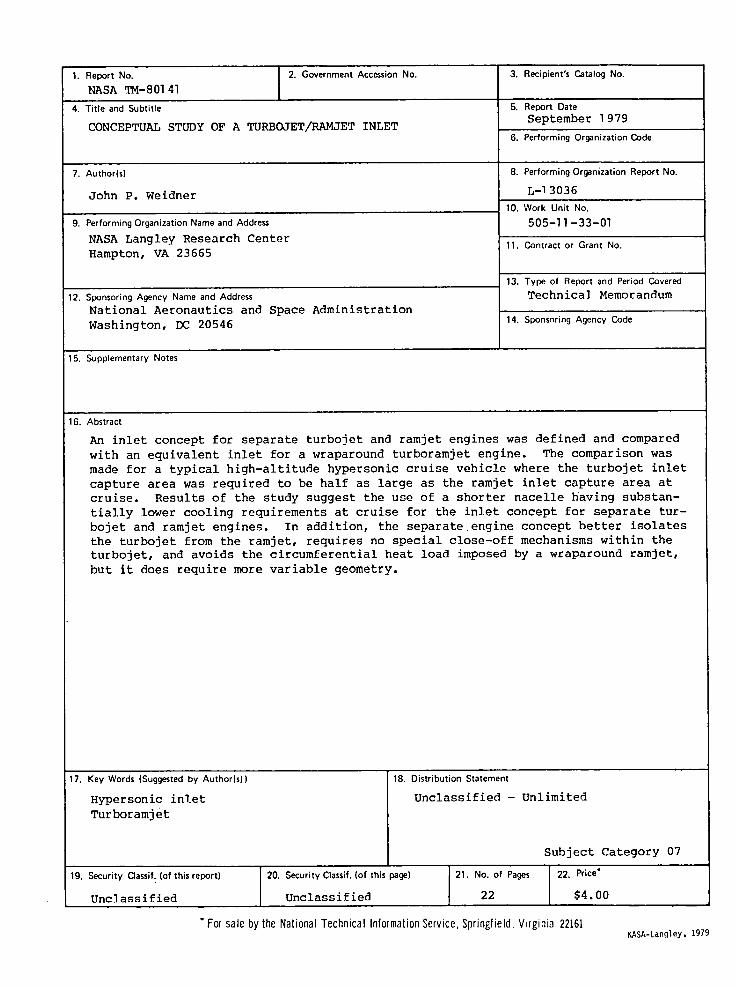
16. Abstract
An inlet concept for separate turbojet and ramjet engines was defined and compared
with an equivalent inlet for a wraparound turboramjet engine. The comparison was
made for a typical high-altitude hypersonic cruise vehicle where the turbojet inlet
capture area was required to be half as large as the ramjet inlet capture area at
cruise. Results of the study suggest the use of a shorter nacelle having substan-
tially lower cooling requirements at cruise for the inlet concept for separate tur-
bojet and ramjet engines. In addition, the separate engine concept better isolates
the turbojet from the ramjet, requires no special close-off mechanisms within the
turbojet, and avoids the circumferential heat load imposed by a wraparound ramjet,
but it does require more variable geometry.
17. Key Words (Sugg_ted by Author(s)) 18. Distribution Statement
Hypersonic inlet Unclassified - Unlimited
Turboramjet
Subject Category 07
19. Security Classif.(of thisreport) 20. SecurityClassif.(of this page) 21. No. of Pages 22. Price"
Unclassified Unclassified 22 $4.00
* For sale by the National Technical Information Service, Springfield, Virginia 22161NASA-Langley,1979

National Aeronauticsand SPECIAL FOURTH CLASS MAIL Postage and Fees Paid
,,_,C"ace Administration BOOK National Aeronautics andSpace AdministrationNASA-451
Washington,D.C.20546Official Business
Penalty for Private Use, $300
_A If Undeliverable (Section 158POSTMASTER:
Postal Manual) Do Not Return