Embed Size (px)
Citation preview

C2000/C2100 ORP/pH Controllers120V/240V
OW
NE
R’S
M
AN
UA
L


IMPORTANT SAFETY INFORMATIONWhen installing and using this electrical equipment, basic safetyprecautions should always be followed including the following:
READ AND FOLLOW ALL INSTALLATION INSTRUCTIONS.
Installation of this equipment should be performed by a licensedelectrician and conform to all National Electric Code (NEC),state and local codes. Installations in Canada must comply to CEC requirements.
WARNING:To reduce the risk of electrical shock:
• Turn off or disconnect the power source before installing,opening the door, or adjusting the internal workings of the controller.
• Install all electrical equipment at least 10 feet (3 m) frominside wall of pool or spa.
• Connect this device only to a grounding-type receptacleprotected by a ground-fault circuit interrupter (GFCI).
• Do not use an extension cord, connect the controllerdirectly into the outlet. Do not bury the cord.
WARNING: To reduce risk of injury, do not permit children to usethis product unless they are closely supervised at all times.
For proper operation, it is imperative that the system has properflow past the sensors when the pool filtration system is running.
When automating a body of water, size the feeders so desiredlevels can be attained in short operating cycles. If feeders areunable to keep up with demand within a short time frame,automation becomes ineffective.
While the system is feeding, inaccurate sanitizer/pH levels maybe displayed because the system is still circulating the chemical.
Observe precautions for electrostatic sensitive devices.
SAVE THESE INSTRUCTIONS.


Table of ContentsSpecificationsIntroduction . . . . . . . . . . . . . . . . . . . . . . . . . . . . . . . . . . . . . . . . .2
Components . . . . . . . . . . . . . . . . . . . . . . . . . . . . . . . . . . . .2Installation . . . . . . . . . . . . . . . . . . . . . . . . . . . . . . . . . . . . . . . . . .4
Feed Systems . . . . . . . . . . . . . . . . . . . . . . . . . . . . . . . . . . .4Controller . . . . . . . . . . . . . . . . . . . . . . . . . . . . . . . . . . . . . . .6Flow Cell/Flow Switch Assembly . . . . . . . . . . . . . . . . . . . . .6
Sensor . . . . . . . . . . . . . . . . . . . . . . . . . . . . . . . . . . . . .10Electrical Connections . . . . . . . . . . . . . . . . . . . . . . . . . . . .10
Adding a Second Controller . . . . . . . . . . . . . . . . . . . . .13System Setup . . . . . . . . . . . . . . . . . . . . . . . . . . . . . . . . . . . . . .14
Controller Display Overview . . . . . . . . . . . . . . . . . . . . . . .15Display Symbols . . . . . . . . . . . . . . . . . . . . . . . . . . . . . .15Navigating the System . . . . . . . . . . . . . . . . . . . . . . . . .16
Setup Screen . . . . . . . . . . . . . . . . . . . . . . . . . . . . . . . . . . .17Watermatic #1 Screen . . . . . . . . . . . . . . . . . . . . . . . . . . . .18ORP Setup Screen . . . . . . . . . . . . . . . . . . . . . . . . . . . . . .19PH Setup Screen . . . . . . . . . . . . . . . . . . . . . . . . . . . . . . . .21
Operation . . . . . . . . . . . . . . . . . . . . . . . . . . . . . . . . . . . . . . . . .23Standby Mode . . . . . . . . . . . . . . . . . . . . . . . . . . . . . . . . . .23Command Center Setup Screen . . . . . . . . . . . . . . . . . . . .24
Maintenance . . . . . . . . . . . . . . . . . . . . . . . . . . . . . . . . . . . . . . .25Cleaning the Sensor Tips . . . . . . . . . . . . . . . . . . . . . . . . .25Checking the ORP Sensor . . . . . . . . . . . . . . . . . . . . . . . .25Checking the pH Sensor . . . . . . . . . . . . . . . . . . . . . . . . . .26Winterizing . . . . . . . . . . . . . . . . . . . . . . . . . . . . . . . . . . . . .26
Warranty . . . . . . . . . . . . . . . . . . . . . . . . . . . . . . . . . . . . . . . . . .27Appendix . . . . . . . . . . . . . . . . . . . . . . . . . . . . . . . . . . . . . . . . . .29

SpecificationspH Control Range: 7.0 to 8.0ORP Control Range: 200 to 900 Input Power: • 120 VAC 50/60 Hz auto-switching when
supplied with 3-wire grounded powercord; GFCI source required.
• 240 VAC 50/60 Hz capable.Controller Power: 1 amp, internally fused.Output Power: • 120 VAC 50/60 Hz auto-switching when
supplied with 3-wire grounded powercord; GFCI source required.
• 240 VAC 50/60 Hz capable.• 8A fuse for 120V, 4A fuse for 240V.• 3 HP (High power - line voltage) and
2 LP (Low power - 24V) built-in relaysDisplay: Graphic, LCD, menu-drivenOperating Temp: 40 - 120° FSensors: pH: glass combination with 10' cable
ORP: platinum combination w/ 10' cableInputs: • Polaris CPC cable with 9-pin connector
ORP & pH sensors: BNC connectorLevel detection: allows feeding, normallyclosed. Flow detection; allows feeding,normally closed
Outputs: • ORP Feeder - High Voltage 120 VAC 50/60 Hz (with 120V input)240 VAC 50/60 Hz; (with 240V input)8A on-board fuse for 120, 4A fuse for240, normally OFF.
• ORP Feeder – Low Voltage, 24V • pH Feeder – High Voltage,
120 VAC 50/60 Hz (with 120V input)240 VAC 50/60 Hz; (with 240V input)8A on-board fuse for 120, 4A fuse for240, normally OFF.
• pH Feeder – Low Voltage, 24V• RS232 for data
2
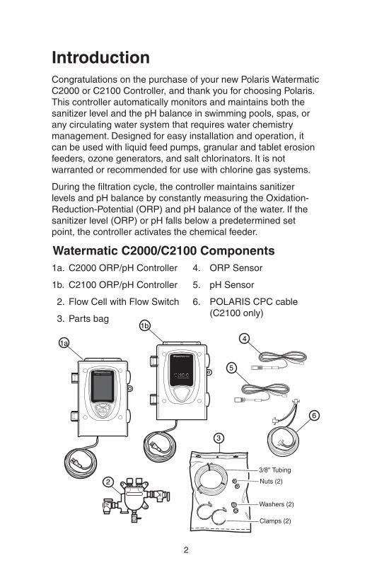
IntroductionCongratulations on the purchase of your new Polaris WatermaticC2000 or C2100 Controller, and thank you for choosing Polaris.This controller automatically monitors and maintains both thesanitizer level and the pH balance in swimming pools, spas, orany circulating water system that requires water chemistrymanagement. Designed for easy installation and operation, itcan be used with liquid feed pumps, granular and tablet erosionfeeders, ozone generators, and salt chlorinators. It is notwarranted or recommended for use with chlorine gas systems.
During the filtration cycle, the controller maintains sanitizer levels and pH balance by constantly measuring the Oxidation-Reduction-Potential (ORP) and pH balance of the water. If thesanitizer level (ORP) or pH falls below a predetermined setpoint, the controller activates the chemical feeder.
1a. C2000 ORP/pH Controller
1b. C2100 ORP/pH Controller
a2. Flow Cell with Flow Switch
a3. Parts bag
4. ORP Sensor
5. pH Sensor
6. POLARIS CPC cable(C2100 only)
Watermatic C2000/C2100 Components
ORP
pH
4
5
1b
2
ENTER
1a
6
6
d
b
c
e
a
Not used,discard
a tank anchorsb pipe connection nutsc pipe connection gasketsd tubing adaptorsc pipe connection clamps
5
3
3/8" Tubing
Nuts (2)
Washers (2)
Clamps (2)
Chemical Automation System
Chemical Automation System
1a
ENTER

3
The C2000 controller is designed to operateindependently as a stand-alone unit.
The C2100 is used with the Polaris EosAutomated Control System.
Both controllers are preset to be used insingle applications (one controller for onebody of water). An additional C2100controller can be added to automate asecond body of water.
The flow cell assemblyhouses the sensors andprovides a sample port formanual testing. It alsocontains an integrated flowswitch/flow indicator thatprevents the feeder(s) fromfeeding if there is insufficientflow. If flow is insufficient, awarning message will flash at the bottom of the screen.
Chemical Automation System
Chemical Automation System
Flow Switch/Flow Indicator
SamplePort
Inlet
Outlet
Sensors
C2100
C2000

4
Installation
Feed System InstallationInstall the chemical pump and erosion feed systems as shown.If the model differs from these systems, refer to the installationmanual provided with it for the appropriate installation method.
Do not install granular feeders below water level.
pH Feed Pump
From Pool
FlowCell
pH Sensor
ORP Sensor
Filter
Heater
Pump
120/240 VAC GFCI Receptacle
To Pool
Chemical Tank
Controller
Flow Switch
To Eos Command Center (C2100 only)
ChlorineFeed Pump
Chemical Tank
Liquid Feeder
Flow Switch
ORP pH
Pump
Hopper
Tank
Heater
Controller
FlowCell
Filter
To Pool
From Pool
WATERMATIC G1000
Heater
120/240 VAC GFCI Source
To Eos Command Center (C2100 only)
Granular Feeder

5
If using an acid feed system, the insertion point must be downstream of all equipment.
Flow Switch
ORP pH
Pump
Heater
Controller
FlowCell
Filter
To Pool
From Pool
Heater
Cell
120/240 VAC GFCI Source
To Eos Command Center (C2100 only)
Salt Chlorinator
pHFeed Pump
From Pool
FlowCell
pH Sensor
ORP SensorFilter
Heater
Pump
To Pool
Chemical Tank
Controller
Check Valve
24V SolenoidValve
Flow Switch
ErosionFeeder
120/240 VAC GFCI Source
To Eos Command Center (C2100 only)
Erosion Feeder

6
Controller InstallationThe controller should be mounted on a wall or other verticalsurface within eight feet of the feeder, at least ten feet away fromthe edge of the water and within six feet of the GFCI powersource. Use mounting screws or anchors to mount the controller.
If installing a C2100, mount the controller within 12 feet of theEos Command Center to facilitate the CPC cable connection.
If two separate bodies of water are to be maintained, add asecond C2100 controller. Mount this controller within 12 feet ofthe C2000 or Eos Command Center, and 6 feet of the GFCIpower source.
Flow Cell Assembly InstallationMount the flow cell on a vertical surface within eight feet of the controller.
Plumb it so the pressure difference between the inlet (flowswitch side) and the outlet is sufficient to ensure flow throughthe flow cell. If the 3/8" tubing provided is being used, aminimum pressure differential of 3 PSI and 0.3 GPM is requiredto activate the flow switch. It is also desirable to have filteredwater pass over the sensors to minimize cleaning.
Flow Switch/Flow Indicator
SamplePort
Inlet
BallValve
Outlet
Compression Fittings with Sensors
BallValve

7
There are four suggested plumbing installations for the flow cell.
1. Plumb the inlet after the filter and the outlet after the heater.
2. Plumb the inlet after the filter and the outlet before thepump. This ensures excellent flow but the flow must beadjusted so the sensors are not subjected to a suctionenvironment. Open the sample port to verify that water isflowing freely from it.
To PoolFrom Pool
FlowCell
pH Sensor
ORP Sensor
Filter
Heater
Pump
Controller
Flow Switch
Pressure DifferentialInstallation
pH
Controller
To Pool
Flow Switch
ORP Flow CellFrom Pool
FilterPump
Pressure/SuctionMethod

8
3. Plumb the inlet before the filter and the outlet after the filter,using an inline filter to minimize the possibility of debriscoming into contact with the sensors. Use this method forsystems with no heater.
4, For installation with a G7500 Cal Hypo feeder, refer to thediagram below.
Be aware that solar systems and other factors can alter pressure differentials in a system, adversely impacting flowthrough the flow cell.
pH
From ConnectionAfter the Filter
Controller
Flow SwitchFlow CellORP
Controller
To Pool
pH Sensor
Filter
Pump
From Pool
Flow Switch
Flow Cell
1/8
NPT
Strainer Assembly #8-110
Pressure DifferentialAlternative Installation

9
The flow cell comes fully assembled, ready to install with the3/8" tubing provided. Other sized tubing or 1/2" hard plumbingcan be used.
To use an alternative tubing, remove the 90 degree on/off valvesand plumb according to the application.
1. If using a saddle clamp, drill a 7/16" hole in the pipe.Insert the 1/8" compression fitting (#2) through the clamp(#3) and place the nylon jam nut (#4) onto the compressionfitting. Slide the pipe seal washer (#5) onto the end of thecompression fitting. Insert the completed assembly into thehole in the pipe and tighten the clamp. Test for leaks.
If the pipe is larger than 2" in diameter, two clamps joinedtogether will be required per each hole.
If using a pipe tap, drill a 7/16" hole and tap a 1/4" NPThole. Be careful not to over tap the hole. Apply Teflon tape tothe threads on the compression fitting and screw securelyinto the pipe. Test for leaks.
2. Cut the tubing (#1) to the appropriate length. Slightly loosenthe compression fitting in the pipe and insert the tubing.Take the free end of the tubing and insert it into thecompression fitting on the flow cell.
1
5
3
2
4

10
Sensor Installation
Unpack the sensors and remove theprotective bottle and o-ring. Set asidethe o-rings. Save the bottles forwinterizing or reshipping.
Remove the compression fitting nutfrom the flow cell and slide it up ontothe sensor. Slide the o-ring from thebottle onto the sensor. Insert thesensor into the compression fitting on the flow cell assembly. The sensortips should extend below the waterline in the flow cell. Hand-tighten thenut of the fitting, do not use a wrench.Coil any extra sensor cableexternally, not in the controller box.
Electrical Connections To complete electrical connects:
1. Verify that power is not connected.
2. For C2100 with Eos install only: Open the Eos CommandCenter door and remove the deadfront. Unscrew and swingdown the hinged board plate to access the command centercircuit board. Unplug the Eos CPC connector from thecommand center board. Plug one end of the Polaris CPCcable into the command center board and the other end intothe CPC cable connected to the Eos activator board.
Controller
Compression Fitting
Sensor Tip
ENTER
ORP
Command Center Board
Polaris CPCCable
Hinged BoardPlate
EosCPCCable

Swing up and secure the hinged board plate. Feed the CPC cable down through the low voltage compartment andout through the bottom of the command center. Reinstall thedeadfront and close the door. Route the CPC cable to theC2100 controller.
3. Open the door to the controller.
4. Unscrew and remove the wire clamp.
5. Strip lead wires (maximum of 3/8") from ORP and pHfeeders. To facilitate wire hook-up, remove output terminalblock from circuit board. Attach feeder output leads to theterminal block. Note the orientation of the leads (ground, line and neutral). Reinstall terminal block.
6. Attach leads from Flow Switch to the Flow terminal block.
7. Attach the pH and ORP sensor BNC connectors to the controller.
8. For C2100 with Eos install only: Connect the Polaris CPC cable from the Eos system to the CPC connector on the controller board.
11
ControllerHousing
1
OP
EN
12
SensorsBNC Connections
120V AC Output for ORP
120V AC Output for pH
FlowSwitch
Wire Clamp
Grommet
CPCConnection
24V AC Outputfor pH / ORP

12
8. Route connections through housing grommets using theappropriate grommet for the wire size.
9. Re-mount the wire clamp. Close door and plug the controllerpower cord into the GFCI receptacle.
Grommets
Wire ClampFor SMALL DiameterCables:
Bend grommet to open slot
For LARGE Diameter Cables:
Tear out grommet center

13
Adding A Second Controller1. If a C2100 is being installed with the C2000, disconnect
the CPC cable at the C2000 controller board. Plug one endof the Polaris CPC cable into the controller board and theother end into the CPC cable connected to the controller’sactivator board.
If the second C2100 is being used with Eos, daisy chainthe CPC connection either at the Eos or the first C2100.
2. Set DIP switch #1 on the second C2100 controller to the ONposition. This identifies the second controller as Watermatic#2 (WM 2) and allows simultaneous use of the controllers.
C2000 Controller Board CPC Connection
CPC Cable to C2100
C2000ActivatorBoard
C2000CPC Cable
ControllerHousing
Controller Board
Dip Switch #1 in ON Position
OP
EN
12
OP
EN
12

14
System SetupDo not add chemicals to the feeders until completing the following start-up operations.
1. Use a DPD test kit to test the water, then manually adjustand balance the pool to acceptable ranges. It may takeseveral hours for the levels to stabilize.
2. With the controller power OFF, turn on the filter pump and check for leaks in the system and flow through the flow cell.
3. Plug in or supply power to the controller. The C2000 displaywill illuminate showing the Setup screen or, if a C2100 isinstalled with an Eos system, the Watermatic Control screenwill become available on the Eos display.
To adjust the brightness or contrast of the display, press the left and right arrow keys simultaneously to open theCommand Center Setup screen. Review the ControllerDisplay Overview section and adjust settings as necessary.
4. To set up the system:
• Get familiar with the screen displays and navigating the system.
• Complete controller configuration

15
Controller Display OverviewMeasurements and setting options are shown on the displayscreen. Adjustments to settings are made with the key pad. Usethe curser control (arrow) keys to move through the screens andthe menu options. Use the enter key to select a particular option.
Display Symbols
Folders indicate that additional screens, menus or setupoptions are available for an item.
Check Boxes are used to turn functions or devices on oroff. Checked = On.
The Up/Down Arrows indicate adjustment options areavailable for the field next to it, and the up or down arrowkeys are used to select or enter the setting.
An item in reverse (white text on black box) indicatescursor is over item or field. Press the Enter key to select the item.
A line in this document (a blank area on the actualscreen) with the Up/Down Arrow symbol next to itindicates a text field that can be named.
Tue, Apr 25 2:04pm
Watermatic # 1
ENTER
ORP 650 PH 7.5
Feeder Manual Status
ORP Feed
PH Feed Feeding
Audible Alarm
Cursor Control
Item Select
Check Box(Checked = On/Active)
Folder Icon(ORP Selected)(PH Not Selected) Level Switch (Unchecked = Off/Inactive)
WM 1 No Flow
Status or Alarm Message
Use left arrow keys to move through screens
Current ORP
Current pH
Feeder Status
Manual Feed
Status or Alarm Message
Feeder Manual Status
ORP Feed
PH Feed OK
Audible AlarmLevel Switch
Current Status
Tue Apr 25 2:04pmWatermatic #1
ORP 650 PH 7.5
Aug
*
Aug
*

16
Navigating the System
Use the cursor control (arrow) keys to move from screen toscreen and through the menu options.
To open the new screen represented by a folder icon:
1. Use keypad arrow keys to move the cursor over the folder.The folder will appear in reverse. (Ex: )
2. Press <Enter> to select the folder and open the new screen.
3. Use the left arrow key to exit the new screen.
To select and adjust an item:
1. Use keypad arrow keys to move the cursor over the item tobe adjusted. (Ex: )
2. Press <Enter> to select the item. The item will flash.
3. Use the up/down keys to choose or enter the setting.
4. Press <Enter> to activate the setting.
To check or uncheck a check box:
1. Use keypad arrow keys to move the cursor over the checkbox.
2. Press <Enter> to enable (Ex: ) or disable (Ex: ) it.
If the screen contrast orbrightness needs to be adjusted,press the left and right arrow keyssimultaneously to open theCommand Center Setup screen.
Contrast controls the readabilityof the test, light or dark, on the screen.
Backlight controls illumination orbrightness of the screen.
Command Center Setup
Wed, Aug 29 2:04pm
Software Versions
Contrast Adjust
Backlight Adjust
Backlight Timeout 3 min
Audible Alarm
Adjust

17
Setup ScreenIf a C2100 is installed with an Eos system, all initial setupinformation is entered via the Eos Command Center. Refer to the Eos Installation and Operations Guide.
For the C2000, the Setup screen will display at start up.
Reset System Selecting this folder icon opens a separate screen which allowsthe user to clear all devicesettings.
Owner InfoSelect this folder to open a screen where owner name,address, etc., can be defined.
Polaris InfoSelect to enter product serialnumber, service centerinformation, etc.
To name the controller:
1. Move the cursor to the blank (line in diagram) area next toWatermatic #1 and press <Enter> to select the field.
2. A line will appear and the first character position of the fieldwill flash. (Ex: )
3. Use the up/down arrow keys to move through the alpha-numeric text options and the left/right keys to move withinthe field.
4. Press <Enter> when the entry is complete.
Set the Date (month, day and year) and the Time (hour with amor pm and minutes).
When all entries are complete, use the left arrow to move to themain Watermatic #1 control screen.
Setup
Tue Apr 25 2:04pm
Reset System Owner Info Polaris Info Watermatic #1 Date Apr 25, 2006Time 02.04pm
To adjust display settings, press and together.
Use left/right key to return to Main screen
Folder Icon(Reset System)
Line indicates text field, actualscreen displayis blank
Aug
*

Watermatic #1 ScreenThe current ORP and pH levels are displayed at the top of the screen.
FeederTo set or adjust the ORP Feederconfiguration, move the curserover the folder icon next to ORPand press <Enter>. The ORPSetup screen will open.
To set or adjust the pH Feederconfiguration, select the foldernext to PH to open the PH Setup screen.
Manual Feed The ORP and pH feeders can be manually activated by movingthe cursor over "Feed" under the Manual heading and pressing<Enter> on the key pad. A confirmation screen displays toconfirm the action before the feeder is activated.
Feed time intervals are specified on the ORP and pH Setupscreens. If the feeder is in delay mode, Manual Feed willoverride and cancel the delay cycle. Manual Feed is disabled byan overfeed or high/low alert, or if the feeder is already feeding.
StatusReflects the activity or status of the respective feeder. This fielddisplays “Feeding” when chemical is being dispensed, “OK”when the sensor readings match the desired levels, is blankduring feed delay cycles and provides specific alert messages ifan alert condition exists. (See Appendix for Alerts and Alarms.)Alert messages also flash at the bottom of the screen.
Audible AlarmActivates an optional, external alarm to signal an out-of-range orother alert status. Move curser to check box, press <Enter> toactivate. An internal (at the board) audible alarm is alsoavailable via the Command Center Setup screen.
Level Switch Activates system recognition of an optional feeder tank chemical level sensor.
18
Tue, Apr 25 2:04pm
Watermatic # 1
ENTER
ORP 650 PH 7.5
Feeder Manual Status
ORP Feed
PH Feed Feeding
Audible Alarm
Cursor Control
Item Select
Check Box(Checked = On/Active)
Folder Icon(ORP Selected)(PH Not Selected) Level Switch (Unchecked = Off/Inactive)
WM 1 No Flow
Status or Alarm Message
Use left arrow keys to move through screens
Current ORP
Current pH
Feeder Status
Manual Feed
Status or Alarm Message
Feeder Manual Status
ORP Feed
PH Feed OK
Audible AlarmLevel Switch
Current Status
Tue Apr 25 2:04pmWatermatic #1
ORP 650 PH 7.5

19
ORP Setup ScreenMove the cursor over the ORP folder icon and press <Enter> toopen the ORP feeder setup screen. Here the ORP set point,feed times, high/low ranges, and other specifications are set.
To set or adjust an item:
1. Move the cursor to the adjustable field next to the symbol.
2. Press <Enter> to select the item. The item will flash.
3. Use the up/down arrow keys to choose the setting.
4. Press <Enter> to activate the setting.
Feeder Specifies feeder type. When a feeder is selected, Feed Time andFeed Delay settings will change to the factory-set, feeder specificdefaults outlined in the Appendix. These defaults can be adjusted.
Feeder options:
Feed Time Designates the amount of time the feeder adds sanitizer.
Delay TimeDesignates a minimum time between feeding. This option is notshown if “Continuous” feed is selected.
ORP SetupWed, Aug 29 2:04pm
Feeder GranularFeed Time 5 secDelay Time 10 MinSet point 650 High Alert 900 Low Alert 100 Wait for pH Stop for pHNext Cleaning Mar 15
Use left arrowkey to return to Main screen
• Granular
• Liquid (Use for OzoneGenerators)
• Salt
• Erosion LP (24V) solenoid
• Erosion HP (line voltage) solenoid

20
Overfeed Sets a maximum time for the ORP to reach the set point. If theset point is not reached, the feeder shuts-down and an alert issignaled. Used only when Feed Time = Continuous, it replacesthe Delay Time option on the display.
SetpointSets the desired level of ORP. Set between 200 and 900 inincrements of 10. The default is 650.
The controller displays direct ORP readings and the control isbased on this, not the parts per million (ppm). While ORPindicates the effectiveness of the sanitizer, it does not directlycorrelate to a ppm reading. Use a DPD test kit to measure thefree chlorine. If more or less sanitizer is needed, adjust the setpoint up or down accordingly. Also note the ORP reading is notlinear. An adjustment from 700 to 750 could increase thesanitizer level by several ppm. The World Health Organizationrecommends an ORP at or above 650.
High Alert Specifies the high end of the acceptable ORP range. Setbetween 650 and 950, in increments of 10, at least 100 greaterthan the set point (if set point 850, High Alert = 950). The defaultof 900 should be appropriate for most applications.
Low AlertSpecifies the low end of the acceptable ORP range. Setbetween 100 and 640, in increments of 10, at least 100 belowthe set point. The default of 100 is usually appropriate.
Wait for pHYes = ORP will not feed at the same time as the pH. The pH willalways feed first. Preventing simultaneous feeding effectivelyreduces current draw on the GFCI circuit. No = ORP can feed atsame time as pH. Default = Yes.
Stop for pHYes = ORP will not feed if the pH is out of range. If the pH goesback in range, the alert clears itself and ORP can feed. No =ORP is allowed to feed regardless of pH. Default = Yes.
Next CleaningSets a date (month and day) for the next sensor cleaning. Simplya reminder display. Default = OFF.

21
PH Setup ScreenMove the cursor over the pH folder icon and press <Enter> toopen the pH feeder setup screen. Here the pH set point, feedtype, feed times and and other specifications are set.
To set or adjust an item:
1. Move the cursor to the adjustable field next to the symbol.
2. Press <Enter> to select the item. The item will flash.
3. Use the up/down arrow keys to choose the setting.
4. Press <Enter> to activate the setting.
FeederThis specifies feeder type. When the feeder is assigned, FeedTime and Feed Delay settings will change to the factory-set,defaults outlined in the Appendix. Defaults can be adjusted.
Feeder options:
• Granular
• Liquid
• Erosion LP (24V) solenoid
• Erosion HP (line voltage) solenoid
Acid/BaseDesignates whether the controller maintains the pH below theset point (acid) or above the set point (base).
PH Setup
Tue, Apr 24 2:04pm
Feeder GranularAcid/Base AcidFeed Time 5 secDelay Time 10 MinSetpoint 7.5High Alert 8.4Low Alert 6.8Next Cleaning OffNext Calibrate May 15Calibrate at PH 7.5
Use left arrow key to return to Main screen

22
Feed TimeDesignates how long the feeder is activated.
Delay Time Sets the amount time between feeding. Not shown when“Continuous” feed is selected.
OverfeedUsed only with “Continuous” feed. if the pH does not reach theset point within the specified time, the feeder shuts-down and analert is signaled.
SetpointSet between 7.0 and 8.2 in increments of 0.1 pH. Default is 7.5.
High Alert Specifies the high end of the acceptable pH range.
Set between 7.5 and 8.4 pH, in increments of 0.1 pH,at least 0.4greater than the set point (if Setpoint 8.0, High Alert = 8.4). Thedefault of 8.4 will be appropriate for most applications.
Low Alert Specifies the low end of the acceptable pH range.
Set between 6.8 and 7.4 pH, in increments 0.1 pH, at least 0.4less than the set point (if Setpoint 7.2, Low Alert = 6.8). Thedefault of 6.8 will usually be appropriate.
Next CleaningSets a date (month and day) for next sensor cleaning. Simply areminder display, the factory default setting is OFF.
Next CalibrationSets a date (month and day) for next sensor calibration. Simplya reminder display, the factory default setting is OFF.
CalibrationAllows user to adjust the pH sensor reading to match the actualpH of the water.
Always use water from the sample port of the flow cell to obtainthe pH reading for calibration.
Since the pH sensor can drift slightly over time and thecalibration will offset this drift, calibrate the sensor at least once a month.

23
OperationThere is a 2-minute delay at startup to allow the circulationsystem to stabilize. After the delay, the display will show actual ORP and pH readings from the sensors and the feederswill activate as necessary.
ORP and pH feed messages (Feeding, OK or blank) willdisplay under Status to indicate current feed cycles.
If the system has insufficient flow or pressure, "No Flow" will beindicated under Status and the controller will not feed. The alertmessage will also flash at the bottom of the screen.
High and low alerts display if the ORP or pH has been out-of-range for ten consecutive minutes or more. During analert, the controller stops activating the feeder. When the out-of-range condition is corrected, the controller automaticallyclears the alert and, after a one-minute delay, activates thefeeder as needed.
Allow the system to operate for a few days. With the filtrationsystem running, retest the levels and adjust the set points if necessary.
To put the controller in Standby Mode (disables feeder controlbut power is still on) press and hold the <Enter> key for fiveseconds. Press any key to reactivate the feeder.
To service the controller, unplug it or disconnect the power.
Tue, Apr 25 2:04pm
Watermatic # 1
ENTER
ORP 650 PH 7.5
Feeder Manual Status
ORP Feed
PH Feed Feeding
Audible Alarm
Cursor Control
Item Select
Check Box(Checked = On/Active)
Folder Icon(ORP Selected)(PH Not Selected) Level Switch (Unchecked = Off/Inactive)
WM 1 No Flow
Status or Alarm Message
Use left arrow keys to move through screens
Current ORP
Current pH
Feeder Status
Manual Feed
Status or Alarm Message
Feeder Manual Status
ORP Feed
PH Feed OK
Audible AlarmLevel Switch
Current Status
Tue Apr 25 2:04pmWatermatic #1
ORP 650 PH 7.5
24
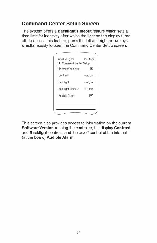
Command Center Setup ScreenThe system offers a Backlight Timeout feature which sets atime limit for inactivity after which the light on the display turnsoff. To access this feature, press the left and right arrow keyssimultaneously to open the Command Center Setup screen.
This screen also provides access to information on the currentSoftware Version running the controller, the display Contrastand Backlight controls, and the on/off control of the internal (at the board) Audible Alarm.
Command Center Setup
Wed, Aug 29 2:04pm
Software Versions
Contrast Adjust
Backlight Adjust
Backlight Timeout 3 min
Audible Alarm

25
Maintenance
Cleaning the Sensor TipsClean sensors once a month to ensure accurate readings. Whendirty, the sensors can read a lower than actual sanitizer/pH leveland can cause too much sanitizer/pH to be dispensed.
Note: A sensor tip coated with calcium scale will not look dirty.
To clean the sensor tip.
1. Turn off the controller. Turn off the filtration system or closethe valves to isolate the flow cell.
2. Loosen the compression-fitting nut and remove the sensorfrom the flow cell assembly.
3. Swirl the tip for five seconds in muriatic acid (diluted 5 to 1)or white vinegar, and rinse it in water. Do not touch, wipe orbrush the end of the sensor. For commercial pools and spas,every third cleaning, swirl the sensor tip in a solution of liquidsoap and water. Rinse with water.
4. Reposition the sensor in the flow cell assembly and turn onthe controller.
5. Allow the controller to operate for a few minutes to get anaccurate reading. Adjust the setting if necessary.
Checking the ORP SensorThe ORP sensor should be checked every six months oranytime the feeder oversanitizes the water.
1. Clean the sensor tip.
2. Put the sensor in a clean glass of tap water. This should give a reading of between 200 and 400. Adding a pinch ofDichlor or Trichlor should cause the ORP level to jump to between 750 and 800. If Dichlor or Trichlor are not available and a sanitizer with a high pH such as calciumhypochlorite or liquid chlorine (sodium hypochlorite) is used,the ORP level may only rise to between 650 and 750.
3. If the sensor does not respond as indicated, the sensorshould be replaced.

26
Checking the pH SensorThe pH sensor should be checked every six months or anytimethe pH goes out of range.
1. Clean the sensor.
2. Place the sensor in a clean glass of tap water. Add a smallamount of acid to the glass. The pH reading should drop.Place the sensor in any solution with a pH above 7.5. ThepH reading should rise.
3. If the sensor does not respond as indicated, the sensor should be replaced.
WinterizingIf the system is located in colder climates, it is important towinterize the system.
1. Turn off the main power to the controller.
2. Gently remove the sensors from the flow cell assembly andstore them in a protective cap or bottle filled with a liquidsolution of one teaspoon salt and three teaspoons water. Mixthe solution thoroughly and make sure it completely coversthe tip of the sensors. Store the sensors in a warm place. Donot expose sensors to freezing temperatures.
3. Drain the water from the flow cell/flow switch assembly.

27
WarrantyPolaris Watermatic C2000/C2100 ORP/pH Controller
This limited warranty is extended to the original consumerpurchaser of this Polaris Watermatic Controller manufactured by Polaris Pool Systems, Inc. ("Polaris"), 2620 Commerce Way,Vista, CA 92081-8438, USA.
Polaris warrants the Watermatic Controller, including all partsand components thereof, to be free of defects in material andworkmanship. For questions regarding your Polaris WatermaticController, please call or write us. Be sure to provide the serialnumber of your unit.
The warranty commences on the date of installation of thecontroller and shall remain in effect for a period of one (1) yearfrom the date of purchase as established by proof of purchaseor two (2) years from the date of manufacture of the controller as established by the serial number, whichever is earlier.
This limited warranty does not apply if the failure is caused orcontributed by any of the following: improper handling, improperstorage, abuse, unsuitable application of the unit, lack ofreasonable and necessary maintenance, winter freezing orrepairs made or attempted by other than Polaris or one of itsAuthorized Service Centers. Polaris will repair or replace, at itsoption, a unit, part or component proved to be defective withinthe warranty period and under the conditions of the warranty.
Unless local repair is authorized, the consumer must deliver or ship the unit or the warranted parts or components, freightprepaid to the nearest Polaris Authorized Service Center orreturn it freight prepaid (after proper authorization) to the plantof manufacture. Authorization to return a unit to the plant ofmanufacture must be obtained from the Polaris CustomerService Department. For your convenience, please check withyour dealer for the local procedure before exercising thiswarranty. If further directions or instructions should be required,contact the Customer Service Department at 1-800-822-7933(USA and Canada only) or 760-599-9600. Be sure to insureshipments against loss or damage during transit.

28
Polaris is not responsible for the cost of removal of the unit,damages occurring during removal or due to removal, any otherexpenses incurred in shipping the unit or parts to or from thefactory or its Authorized Service Centers, or the installation ofthe repaired or replacement unit. The consumer must bear theseexpenses. This warranty does not cover repair of a unit except atour factory or a Polaris Authorized Service Center.
REPAIR OR REPLACEMENT AS PROVIDED UNDER THISLIMITED WARRANTY IS THE EXCLUSIVE REMEDY OF THECONSUMER. THIS LIMITED WARRANTY IS IN LIEU OF ALLOTHER WARRANTIES, EXPRESS OR IMPLIED, INCLUDINGTHE IMPLIED WARRANTIES OF MERCHANTABILITY ANDFITNESS FOR A PARTICULAR PURPOSE, AND ALL SUCHOTHER WARRANTIES ARE DISCLAIMED EXCEPT TO THEEXTENT ANY IMPLIED WARRANTY MAY BE IMPOSED BYSTATE CONSUMER LAW. ANY SUCH IMPLIED WARRANTYIMPOSED BY STATE CONSUMER LAW IS LIMITED INDURATION TO ONE (1) YEAR FROM DATE OF PURCHASE.IN NO EVENT SHALL POLARIS BE LIABLE FOR INCIDENTALOR CONSEQUENTIAL DAMAGES OF ANY NATURE OR KINDOR FOR DAMAGES TO PERSONS OR PROPERTY,INCLUDING ANY DAMAGE RESULTING FROM THE USE OFTHE POLARIS WATERMATIC CONTROLLER. THE ONLYREMEDY PROVIDED TO YOU UNDER AN APPLICABLEIMPLIED WARRANTY AND THE LIMITED WARRANTY SETFORTH ABOVE SHALL BE THE REMEDIES EXPRESSLYPROVIDED FOR UNDER THIS LIMITED WARRANTY.
This limited warranty gives you specific legal rights.You mayalso have other rights that may vary from state to state. Somestates do not allow limitations on how long an implied warrantylasts, or the exclusion or limitation of incidental or consequentialdamages, so the above limitations may not apply to you.
This limited warranty is valid only in the United States of America and Canada, and it does not apply to PolarisWatermatic Controllers sold or installed in any other country.

29
Appendix
Feed Times and Delay TimesThe default feeding mode for the controller is continuous feed.However, when the ORP or pH feeder type is specified duringsetup, the Feed Time and Delay Time defaults change to thefeeder specific defaults listed below. The listed options are alsoavailable and the ORP and pH sides of the controller can bemodified independently.
After allowing the system to run for a few days, adjust the ORPand/or pH settings as needed. Lengthen the feed cycle if thewater is undersanitized or shorten it if the water is oversanitized.Shorten the delay time if the feeder cannot keep up with demand.
Granular Feeder
Feed Time Delay Time Overfeed(Min.) (Min.)
Options 0.5, 1, 2, 3, 4, 5 Sec. 1 – 99 Off
Defaults 5 Sec. 10 min Off
Liquid Feeder (Use for Ozone Generators)
Feed Time Delay Time Overfeed(Min.) (Min.)
Options Continuous Off 1 - 99
5, 10, 15, 20, 30 Sec. 1 - 99 Off1, 2, 3, 4, 5, 10, 15 Min.
Defaults 10 Min. 10 min Off
Erosion Feeder
Feed Time Delay Time Overfeed(Min.) (Min.)
Options: Continuous Off 1 - 99
5, 10, 15, 20, 30 Sec. 1 - 99 Off1, 2, 3, 4, 5, 10, 15 Min.
Default 10 Min. 10 min Off
Erosion LP = Low power (24V) solenoidErosion HP = High power (line voltage) solenoid

30
Alerts and AlarmsThe following alert conditions will sound the audible alarm:
• WM 1 High PH Alert
• WM 1 Low PH Alert
• WM 1 High ORP Alert
• WM 1 Low ORP Alert
• WM 1 PH Overfeed
• WM 1 ORP Overfeed
• WM 1 Feeder Empty (if Level Switch is selected.)
Each of these alerts are also present on the secondcontroller (Watermatic #2 or WM 2) if one is added to the system.
The following alert conditions will not sound the Alarm:
• WM 1 No Flow
• WM 1 2-Minute Flow Delay
• WM 1 Clean PH Sensor
• WM 1 Cal PH Sensor
• WM 1 Clean ORP Sensor
Again, these alerts are present on the additional controller(Watermatic #2 or WM 2) if it is added to the system
Salt Chlorinator
Feed Time Delay Time Overfeed(Min.) (Hrs.)
Options Continuous Off Off, 4, 8,12, 24 hrs
Defaults Continuous Off 12 hrs

©2006 Polaris Pool Systems, Inc. All rights reserved. TL-447 6/06