Embed Size (px)
Citation preview

KTR-11 Face/Badge Reader
Installation Manual

Copyright Copyright © 2006, GE Security Inc. All rights reserved.
This document may not be copied or otherwise reproduced, in whole or in part, except as specifically permitted under US and international copyright law, without the prior written consent from GE.
Document number/revision: 1055862A (May 2006).
Disclaimer THE INFORMATION IN THIS DOCUMENT IS SUBJECT TO CHANGE WITHOUT NOTICE. GE ASSUMES NO RESPONSIBILITY FOR INACCURACIES OR OMISSIONS AND SPECIFICALLY DISCLAIMS ANY LIABILITIES, LOSSES, OR RISKS, PERSONAL OR OTHERWISE, INCURRED AS A CONSEQUENCE, DIRECTLY OR INDIRECTLY, OF THE USE OR APPLICATION OF ANY OF THE CONTENTS OF THIS DOCUMENT. FOR THE LATEST DOCUMENTATION, CONTACT YOUR LOCAL SUPPLIER OR VISIT US ONLINE AT WWW.GESECURITY.COM.
This publication may contain examples of screen captures and reports used in daily operations. Examples may include fictitious names of individuals and companies. Any similarity to names and addresses of actual businesses or persons is entirely coincidental.
Trademarks and patents GE and the GE monogram are registered trademarks of General Electric.
Other trade names used in this document may be trademarks or registered trademarks of the manufacturers or vendors of the respective products.
Intended use Use this product only for the purpose it was designed for; refer to the data sheet and user documentation. For the latest product information, contact your local supplier or visit us online at www.gesecurity.com.
iii
Contents
Preface . . . . . . . . . . . . . . . . . . . . . . . . . . . . . . . . . . . . . . . . . . . . . . . . . . . . . . . . . . . . . . . . . . . . . . . . . . . . . 1Conventions used in this document. . . . . . . . . . . . . . . . . . . . . . . . . . . . . . . . . . . . . . . . . . . . . . . . . . . . . . . . . . . . . . . . . . . . . . . .1Safety terms and symbols . . . . . . . . . . . . . . . . . . . . . . . . . . . . . . . . . . . . . . . . . . . . . . . . . . . . . . . . . . . . . . . . . . . . . . . . . . . . . . . .1
Product overview . . . . . . . . . . . . . . . . . . . . . . . . . . . . . . . . . . . . . . . . . . . . . . . . . . . . . . . . . . . . . . . . . . . . 2
Installation . . . . . . . . . . . . . . . . . . . . . . . . . . . . . . . . . . . . . . . . . . . . . . . . . . . . . . . . . . . . . . . . . . . . . . . . . 3Cable and wiring requirements . . . . . . . . . . . . . . . . . . . . . . . . . . . . . . . . . . . . . . . . . . . . . . . . . . . . . . . . . . . . . . . . . . . . . . . . . . . .3
Indoor installation . . . . . . . . . . . . . . . . . . . . . . . . . . . . . . . . . . . . . . . . . . . . . . . . . . . . . . . . . . . . . . . . . . . 4Flush-mount installation . . . . . . . . . . . . . . . . . . . . . . . . . . . . . . . . . . . . . . . . . . . . . . . . . . . . . . . . . . . . . . . . . . . . . . . . . . . . . . . . . .4Frame-mount installation . . . . . . . . . . . . . . . . . . . . . . . . . . . . . . . . . . . . . . . . . . . . . . . . . . . . . . . . . . . . . . . . . . . . . . . . . . . . . . . . .5Surface-mount installation . . . . . . . . . . . . . . . . . . . . . . . . . . . . . . . . . . . . . . . . . . . . . . . . . . . . . . . . . . . . . . . . . . . . . . . . . . . . . . . .6
Outdoor installation . . . . . . . . . . . . . . . . . . . . . . . . . . . . . . . . . . . . . . . . . . . . . . . . . . . . . . . . . . . . . . . . . 7Wall-mount installation . . . . . . . . . . . . . . . . . . . . . . . . . . . . . . . . . . . . . . . . . . . . . . . . . . . . . . . . . . . . . . . . . . . . . . . . . . . . . . . . . . .7
Pedestal-mount installation . . . . . . . . . . . . . . . . . . . . . . . . . . . . . . . . . . . . . . . . . . . . . . . . . . . . . . . . . . . . . . . . . . . . . . . . . . . . . . .9
Speaker shroud installation. . . . . . . . . . . . . . . . . . . . . . . . . . . . . . . . . . . . . . . . . . . . . . . . . . . . . . . . . . 10
Configuration . . . . . . . . . . . . . . . . . . . . . . . . . . . . . . . . . . . . . . . . . . . . . . . . . . . . . . . . . . . . . . . . . . . . . . 11Digital control cable . . . . . . . . . . . . . . . . . . . . . . . . . . . . . . . . . . . . . . . . . . . . . . . . . . . . . . . . . . . . . . . . . . . . . . . . . . . . . . . . . . . . 11
Call return cable . . . . . . . . . . . . . . . . . . . . . . . . . . . . . . . . . . . . . . . . . . . . . . . . . . . . . . . . . . . . . . . . . . . . . . . . . . . . . . . . . . . . . . . . 12Audio cable . . . . . . . . . . . . . . . . . . . . . . . . . . . . . . . . . . . . . . . . . . . . . . . . . . . . . . . . . . . . . . . . . . . . . . . . . . . . . . . . . . . . . . . . . . . . 13Door control cables . . . . . . . . . . . . . . . . . . . . . . . . . . . . . . . . . . . . . . . . . . . . . . . . . . . . . . . . . . . . . . . . . . . . . . . . . . . . . . . . . . . . . 13
Operation. . . . . . . . . . . . . . . . . . . . . . . . . . . . . . . . . . . . . . . . . . . . . . . . . . . . . . . . . . . . . . . . . . . . . . . . . . 16Site programming . . . . . . . . . . . . . . . . . . . . . . . . . . . . . . . . . . . . . . . . . . . . . . . . . . . . . . . . . . . . . . . . . . . . . . . . . . . . . . . . . . . . . . 18
Contacting technical support . . . . . . . . . . . . . . . . . . . . . . . . . . . . . . . . . . . . . . . . . . . . . . . . . . . . . . . . 19Online publication library . . . . . . . . . . . . . . . . . . . . . . . . . . . . . . . . . . . . . . . . . . . . . . . . . . . . . . . . . . . . . . . . . . . . . . . . . . . . . . . 19

KTR-11 Face/Badge ReaderInstallation Manual
iv
1
PrefaceThis is the GE KTR-11 Face/Badge Reader Installation Manual. This document includes an overview of the product and detailed instructions explaining:
• how to install a KTR-11 in several indoor and outdoor setups; and• how to configure and operate your KTR-11 within a Digiplex system.
There is also information describing how to contact technical support if you have questions or concerns.
To use this document effectively, you should have the following minimum qualifications:
• a basic knowledge of construction; • a basic knowledge of CCTV systems and components; and• a basic knowledge of electrical wiring and low-voltage electrical connections.
Read these instructions and all ancillary documentation entirely before installing or operating this product. The most current versions of this and related documentation may be found on our website. Refer to Online publication library on page 19 for instructions on accessing our online publication library.
Note: A qualified service person, complying with all applicable codes, should perform all required hardware installation.
Conventions used in this document
The following conventions are used in this document:
Safety terms and symbols
These terms may appear in this manual:
Bold Menu items and buttons.
Italic Emphasis of an instruction or point; special terms.
File names, path names, windows, panes, tabs, fields, variables, and other GUI elements.
Titles of books and various documents.
Blue italic (Electronic version.) Hyperlinks to cross-references, related topics, and URL addresses.
Monospace Text that displays on the computer screen.
Programming or coding sequences.
CAUTION: Cautions identify conditions or practices that may result in damage to the equipment or other property.
WARNING: Warnings identify conditions or practices that could result in equipment damage or serious personal injury.

KTR-11 Face/Badge ReaderInstallation Manual
2
Product overviewGE Security’s KTR-11 face/badge reader is used to control access to a facility. A single keypad controller can control up to 512 KTR-11 units. In general, the KTR-11 operates in the following sequence:
1. A person requesting access at the KTR-11 site places his/her identification in the badge box and presses the call button. The keypad controller receives the call and displays its site number.
2. When the operator at the control location selects the site, (1) two-way audio communication and control of the entry point are established; and (2) the face of the caller appears on the monitor screen.
3. The operator may then send commands to the KTR-11 to select face and face/badge camera views, raise or lower the face camera’s mirror, open the door, gate, or turnstile, etc.
The above sequence describes the face/badge reader’s operation in a standalone setting. However, one or more KTR-11s can also be used as receiver sites in GE Security’s Digiplex system. All units would be linked to a GE Security KTD-304A keypad, which also controls pan/tilt/zoom functions for other Digiplex components.
3
InstallationInstallation of the KTR-11 involves mounting the unit, making cable connections, and programming the site.
Cable and wiring requirements
The following cables and wires should be in place and ready for connection before the KTR-11 is installed:
• Control cable (RS-422) from the keypad: 22 AWG twisted-pair.• Return cable for DTMF signal (1 Vp-p line level) from KTR-11 to the keypad: 22 AWG twisted-pair.• Audio cable, for two-way conversation between the keypad and KTR-11: 18 AWG twisted-pair with
shield. (This cable must be shielded, and must not be included in the jacket of any other cable.)• Video cable: 75 ohm coaxial cable• Power supply: 24 VAC supply line (or optional 115 VAC)
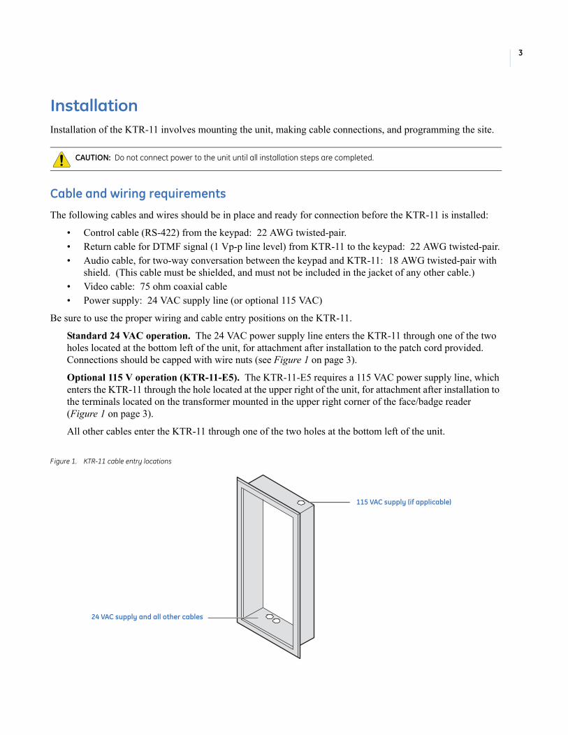
Be sure to use the proper wiring and cable entry positions on the KTR-11.
Standard 24 VAC operation. The 24 VAC power supply line enters the KTR-11 through one of the two holes located at the bottom left of the unit, for attachment after installation to the patch cord provided. Connections should be capped with wire nuts (see Figure 1 on page 3).
Optional 115 V operation (KTR-11-E5). The KTR-11-E5 requires a 115 VAC power supply line, which enters the KTR-11 through the hole located at the upper right of the unit, for attachment after installation to the terminals located on the transformer mounted in the upper right corner of the face/badge reader (Figure 1 on page 3).
All other cables enter the KTR-11 through one of the two holes at the bottom left of the unit.
Figure 1. KTR-11 cable entry locations
CAUTION: Do not connect power to the unit until all installation steps are completed.
115 VAC supply (if applicable)
24 VAC supply and all other cables

KTR-11 Face/Badge ReaderInstallation Manual
4
Indoor installationThe KTR-11 face/badge reader is housed in a stainless steel enclosure designed primarily for flush mounting. However, a surface mounting flange is available for situations where flush mounting is not possible.
Flush-mount installation
The KTR-11 is designed to be easily mounted in almost any wall using KTR-11-15 wall brackets (included). To flush-mount the unit, do the following:
1. Make wall cutout to the dimensions of 20.4 x 9.2 x 3.75 in. (HxWxD). The bottom of the cutout should be 48 in. from the floor (Figure 2).
2. Bring wires and cables into the KTR-11 through the appropriate openings and insert the KTR-11 unit in the wall cutout.
3. Slide the wall brackets into the slots at the top and bottom of the KTR-11, as shown.
4. Thread the screws provided through the slots in the brackets, but do not tighten.
5. Pull each bracket firmly toward the front so that the drywall is pinched securely between the bracket and the KTR-11 frame, and tighten the screws.
Figure 2. Flush-mount installation using KTR-11-15 wall brackets
9.2 in.
(234 mm)
20.4 in.
(518 mm)
48 in. to floor
(1.22 m)
Cut hole in wall as shown.Wall may be 0.5 to 1.0 in. thick.
KTR-11-15 wall brackets
5
Frame-mount installation
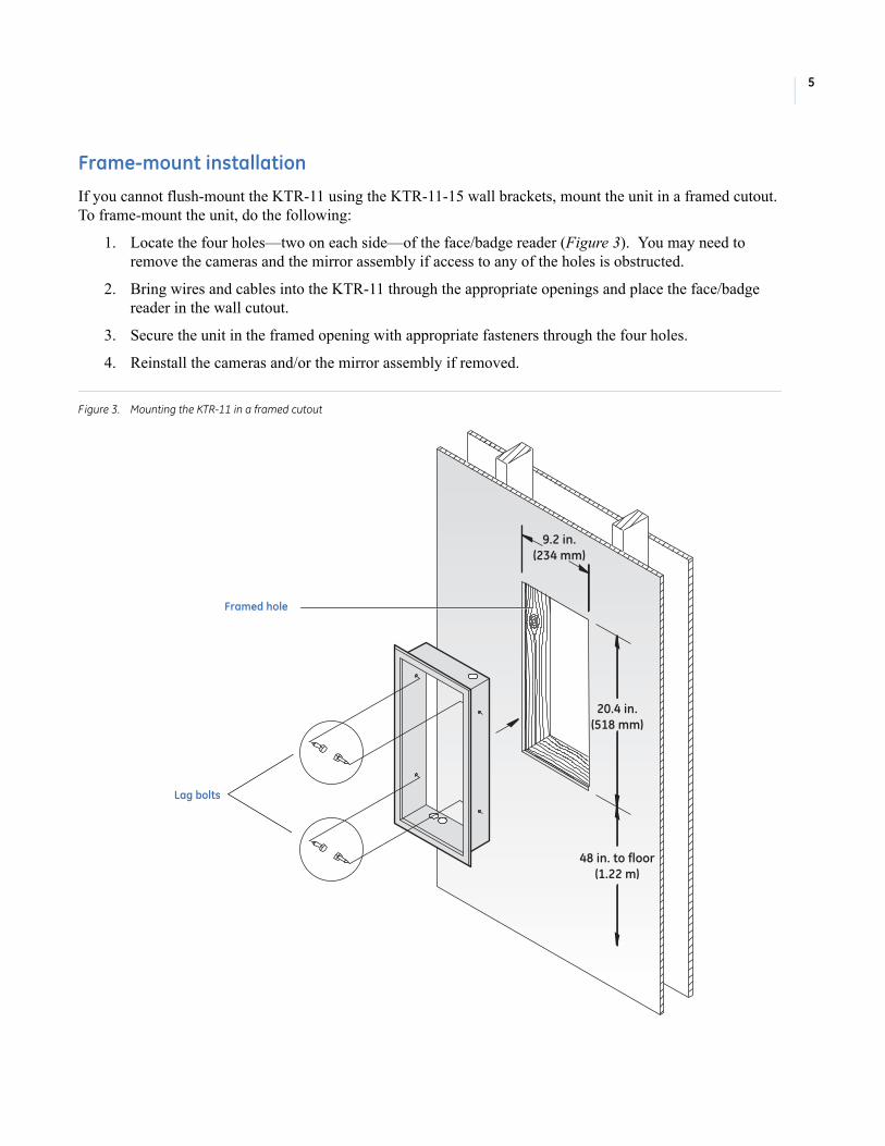
If you cannot flush-mount the KTR-11 using the KTR-11-15 wall brackets, mount the unit in a framed cutout. To frame-mount the unit, do the following:
1. Locate the four holes—two on each side—of the face/badge reader (Figure 3). You may need to remove the cameras and the mirror assembly if access to any of the holes is obstructed.
2. Bring wires and cables into the KTR-11 through the appropriate openings and place the face/badge reader in the wall cutout.
3. Secure the unit in the framed opening with appropriate fasteners through the four holes.
4. Reinstall the cameras and/or the mirror assembly if removed.
Figure 3. Mounting the KTR-11 in a framed cutout
9.2 in.
(234 mm)
20.4 in.
(518 mm)
48 in. to floor
(1.22 m)
Lag bolts
Framed hole
KTR-11 Face/Badge ReaderInstallation Manual
6
Surface-mount installation
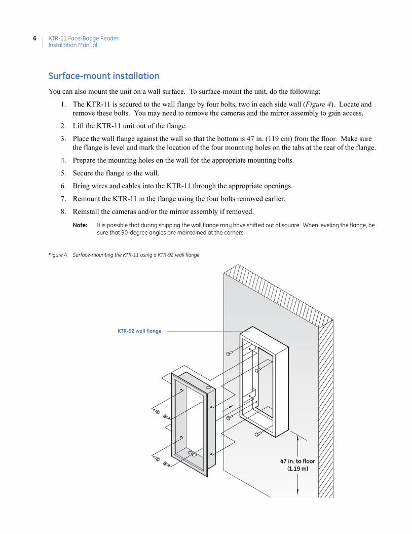
You can also mount the unit on a wall surface. To surface-mount the unit, do the following:
1. The KTR-11 is secured to the wall flange by four bolts, two in each side wall (Figure 4). Locate and remove these bolts. You may need to remove the cameras and the mirror assembly to gain access.
2. Lift the KTR-11 unit out of the flange.
3. Place the wall flange against the wall so that the bottom is 47 in. (119 cm) from the floor. Make sure the flange is level and mark the location of the four mounting holes on the tabs at the rear of the flange.
4. Prepare the mounting holes on the wall for the appropriate mounting bolts.
5. Secure the flange to the wall.
6. Bring wires and cables into the KTR-11 through the appropriate openings.
7. Remount the KTR-11 in the flange using the four bolts removed earlier.
8. Reinstall the cameras and/or the mirror assembly if removed.
Note: It is possible that during shipping the wall flange may have shifted out of square. When leveling the flange, be sure that 90-degree angles are maintained at the corners.
Figure 4. Surface-mounting the KTR-11 using a KTR-92 wall flange
47 in. to floor
(1.19 m)
KTR-92 wall flange

7
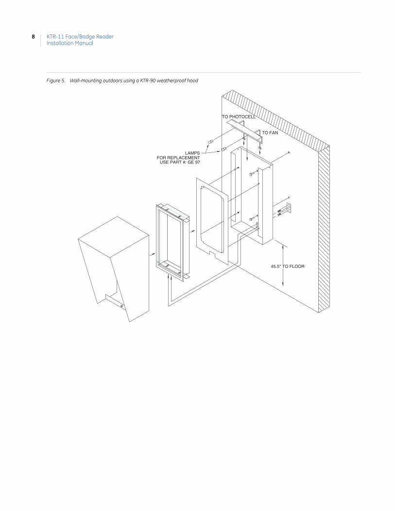
Outdoor installationFor outdoor use, the KTR-11 is surface-mounted on an outside wall using the KTR-90 weatherproof hood assembly. The hood assembly is also used with the KTR-91 pedestal for free standing installation.
In situations where the KTR-11 will be located outdoors and exposed to the elements, the unit should be installed using the KTR-90 weatherproof hood assembly. The hood assembly consists of four parts: casing, hood, trim plate, and light fixture.
Note: The KTR-90 weatherproof hood comes with a heater/fan/light assembly and requires 115 VAC for operation; it is equipped with a 24 V step-down transformer for providing the correct power to the KTR-11.
Wall-mount installation
1. Place the casing against the wall so that the bottom is 45.5 in. (116 cm) from the floor (Figure 5 on page 8). Make sure the casing is level, and mark the location of the two mounting holes in the back.
2. Prepare the mounting holes on the wall for the appropriate mounting bolts.
3. Thread the cables and wires through the two larger holes in the back of the casing, and secure the casing to the wall.
4. Install the trim plate (with the angled light aperture at the top) by inserting the four threaded studs through the holes in the front flange of the casing and securing with nuts.
5. Bring wires and cables into the KTR-11 through the appropriate openings and place the KTR-11 unit in the opening in the trim plate. Slide the wall brackets (KTR-11-15) into the slots at the top and bottom of the KTR-11, as shown.
Insert the screws provided through the slots in the brackets, but do not tighten. Pull each bracket firmly toward the front so that the trim plate is pinched securely between the bracket and the KTR-11 frame. While keeping the bracket tight against the trim plate, tighten the screws to secure the bracket.
Note: When installing the KTR-11 with a weatherproof hood, the wall brackets (KTR-11-15) must be shortened to allow enough room to insert them into both slots at the top and bottom of the KTR-11. To accomplish this, shear 0.65 in. from each end of both brackets before installing. A decal has been placed at each end of the mounting brackets to guide your cuts.
6. Make power and heater/fan connections at the ends of the light fixture as shown. Slide the light fixture onto the front flange of the casing until it is flush with the top of the casing.
7. To install the hood, tilt it back slightly and slide it down over the casing until the pivots inside the hood rest in the notches at the top of either side of the casing. Swing the bottom of the hood in until it stops. Lock the hood in place with the key lock in the bottom cross piece of the hood.
KTR-11 Face/Badge ReaderInstallation Manual
8
Figure 5. Wall-mounting outdoors using a KTR-90 weatherproof hood
TO FAN
TO PHOTOCELL
LAMPSFOR REPLACEMENT
USE PART #: GE 97
45.5" TO FLOOR

9
Pedestal-mount installation
For a free-standing installation, you will need to mount the KTR-11 using a KTR-91 pedestal, which is equipped with a base collar, and is used in conjunction with a KTR-90 weatherproof hood assembly. Install the pedestal as follows:
1. Mount four 1/2 in. diameter studs in a concrete mount in the pattern shown in Figure 6. Thread a nut all the way to the bottom of each stud.
2. Slide the base collar over the top of the pedestal. (The collar fits snugly around the pedestal and will not slide past the cables and wires once they have been pulled through to the outside of the pedestal.)
3. Feed cables and wires up through the pedestal and out the two holes in the upper end of the pedestal.
4. Place the base of the pedestal on the mounting studs and secure with lock washers and nuts. Using a level, bring the pedestal into plumb by adjusting the bottom nuts. When the pedestal is plumb, tighten the top nuts securely. Place the base collar over the studs and lock it in place with the screws provided.
5. Thread the cables and wires through the large holes in the casing. Match the mounting holes in the casing to those in the pedestal, and secure the casing to the pedestal with the bolts provided.
6. Follow instructions explained in Wall-mount installation on page 7 to complete the installation.
Figure 6. Pedestal mounting the KTR-11 using a KTR-90 weatherproof hood
TO FAN
TO PHOTOCELL
LAMPSFOR REPLACEMENT
USE PART #: GE 97
4"
7"
STUD LAYOUT PATTERN
KTR-11 Face/Badge ReaderInstallation Manual
10
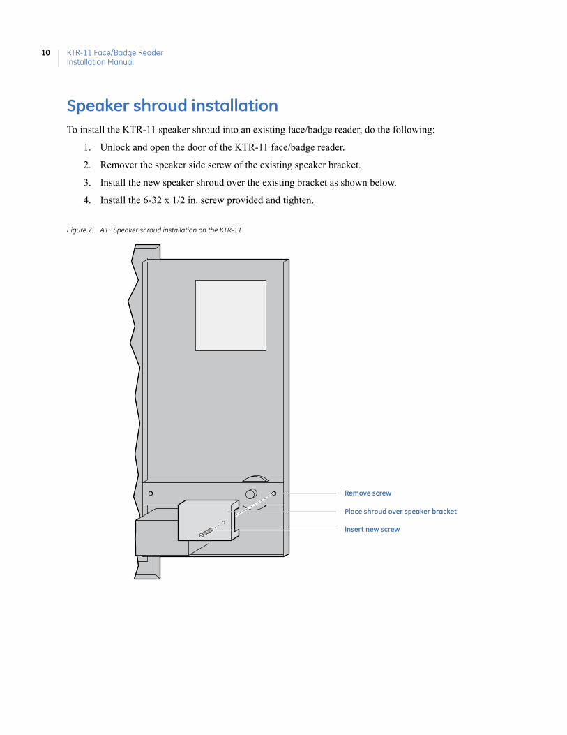
Speaker shroud installationTo install the KTR-11 speaker shroud into an existing face/badge reader, do the following:
1. Unlock and open the door of the KTR-11 face/badge reader.
2. Remover the speaker side screw of the existing speaker bracket.
3. Install the new speaker shroud over the existing bracket as shown below.
4. Install the 6-32 x 1/2 in. screw provided and tighten.
Figure 7. A1: Speaker shroud installation on the KTR-11
Place shroud over speaker bracket
Insert new screw
Remove screw
11
ConfigurationAfter physically installing the unit, you will need to configure it to operate within your system.
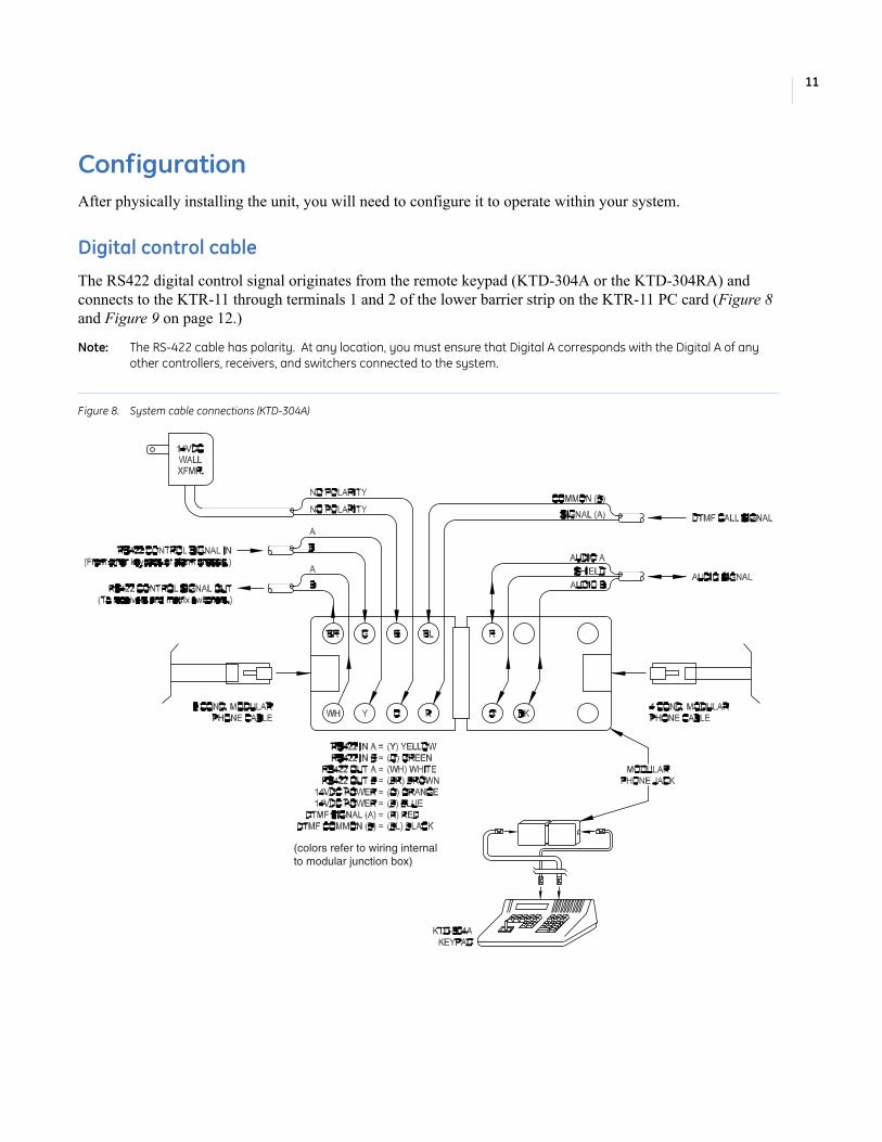
Digital control cable
The RS422 digital control signal originates from the remote keypad (KTD-304A or the KTD-304RA) and connects to the KTR-11 through terminals 1 and 2 of the lower barrier strip on the KTR-11 PC card (Figure 8 and Figure 9 on page 12.)
Note: The RS-422 cable has polarity. At any location, you must ensure that Digital A corresponds with the Digital A of any other controllers, receivers, and switchers connected to the system.
Figure 8. System cable connections (KTD-304A)
(colors refer to wiring internalto modular junction box)
KTR-11 Face/Badge ReaderInstallation Manual
12
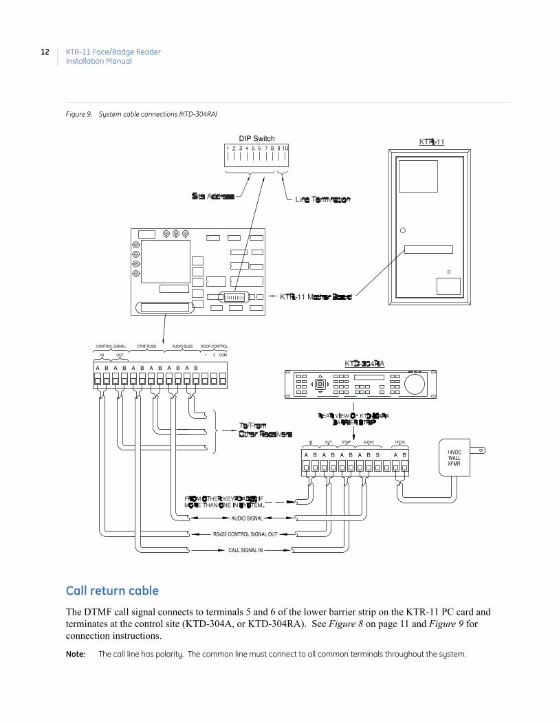
Figure 9. System cable connections (KTD-304RA)
Call return cable
The DTMF call signal connects to terminals 5 and 6 of the lower barrier strip on the KTR-11 PC card and terminates at the control site (KTD-304A, or KTD-304RA). See Figure 8 on page 11 and Figure 9 for connection instructions.
Note: The call line has polarity. The common line must connect to all common terminals throughout the system.
zoomin
auto
outzoom
farfocus
nearfocus
openiris
closeiris
set
7
4
1
0
8
5
2
clear
9
6
3
overbadgeface
mon seq alarm door 1
talk1st
stop aux 1
volvol
access controlvideo switcher controlsite selectpan/tilt/alarm control
door 2
closeopen
focusauto
A B A B A B BASBA
RS422 CONTROL SIGNAL OUT
AUDIO SIGNAL
CALL SIGNAL IN
WALL
14VDC
XFMR.
AUDIO 14VDCDTMFOUTIN
BA
OUT
A ABBABB AA
IN
CONTROL SIGNAL DTMF BUSS AUDIO BUSS DOOR CONTROL
1 2 COM.
B
DIP Switch

13
Audio cable
The two-way audio cable connects to terminal positions 9 and 10 of the lower barrier strip on the KTR-11 PC card, and terminates at the control site (KTR304A or 304RA). See Figure 8 on page 11 and Figure 9 on page 12. The cable’s shield should be continuous throughout its length and should remain unattached at all points except at the control site.
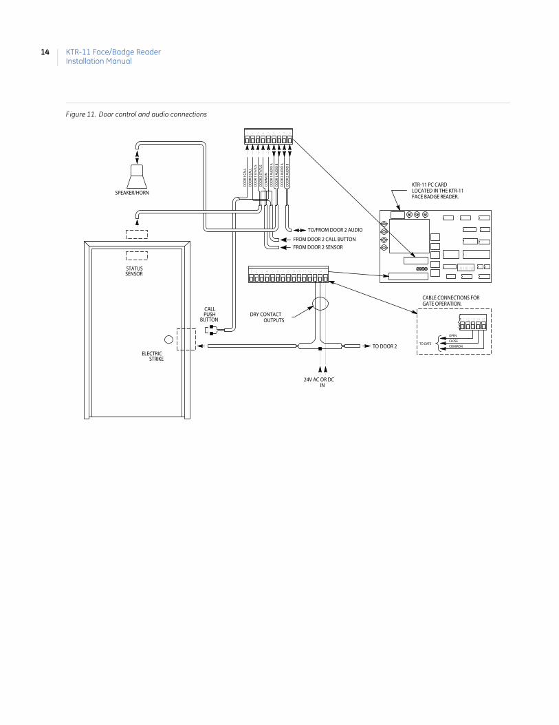
Door control cables
The KTR-11 PC card contains two relays that provide dry contacts (1 A at 24 V) for door control. See Figure 10 and Figure 11 on page 14 for connection details.
Figure 10. Door control and audio connections KTD-304A
DO
OR
1 S
TATU
S
CO
MM
ON
DO
OR
2 S
TATU
S
FROM DOOR 2 SENSOR
SENSOR
ELECTRICSTRIKE
DO
OR
1 C
ALL
DO
OR
2 C
ALL
FROM DOOR 2 CALL BUTTON
STATUS
CALLPUSH
BUTTON
DO
OR
1 A
UD
IO A
DO
OR
1 A
UD
IO B
SPEAKER/HORN
DO
OR
2 A
UD
IO B
DO
OR
2 A
UD
IO A
TO/FROM DOOR 2 AUDIO
KTR-11 PC CARDLOCATED IN THE KTR-11FACE BADGE READER.
OPENCLOSECOMMON
TO GATE
CABLE CONNECTIONS FORGATE OPERATION.
24V AC OR DCIN
TO DOOR 2
DRY CONTACTOUTPUTS
KTR-11 Face/Badge ReaderInstallation Manual
14
Figure 11. Door control and audio connections
DO
OR
1 ST
ATU
S
COM
MO
N
DO
OR
2 ST
ATU
S
FROM DOOR 2 SENSOR
SENSOR
ELECTRICSTRIKE
DO
OR
1 CA
LL
DO
OR
2 CA
LL
FROM DOOR 2 CALL BUTTON
STATUS
CALLPUSH
BUTTON
987654321
151413121110987654321D
OO
R 1
AU
DIO
A
DO
OR
1 A
UD
IO B
SPEAKER/HORN
DO
OR
2 A
UD
IO B
DO
OR
2 A
UD
IO A
TO/FROM DOOR 2 AUDIO
KTR-11 PC CARDLOCATED IN THE KTR-11FACE BADGE READER.
1514131211
OPEN
CLOSE
COMMONTO GATE
CABLE CONNECTIONS FORGATE OPERATION.
24V AC OR DCIN
TO DOOR 2
DRY CONTACTOUTPUTS

15
Figure 12. Video connections
BA
DG
E V
IDE
O
FA
CE
CA
M.
GE
N. L
OC
K
FA
CE
VID
EO
24V
AC
TO
FA
CE
CA
M
24V
AC
TO
BA
DG
E C
AM
FACECAMERA
BADGECAMERA
DOOR 1CAMERA
CA
ME
RA
OV
ER
VIE
W
CAMERADOOR 2
VIDEO OUTPUT
KTR-11 Face/Badge ReaderInstallation Manual
16
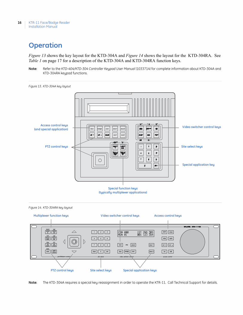
OperationFigure 13 shows the key layout for the KTD-304A and Figure 14 shows the layout for the KTD-304RA. See Table 1 on page 17 for a description of the KTD-304A and KTD-304RA function keys.
Note: Refer to the KTD-404/KTD-304 Controller Keypad User Manual (1033714) for complete information about KTD-304A and KTD-304RA keypad functions.
Figure 13. KTD-304A key layout
Figure 14. KTD-304RA key layout
Note: The KTD-304A requires a special key reassignment in order to operate the KTR-11. Call Technical Support for details.
face badge over door1 door2
aux1 aux2
Video switcher control keys
Site select keys
Special application key
Access control keys(and special application)
PTZ control keys
Special function keys(typically multiplexer applications)
zoomin
auto
outzoom
farfocus
nearfocus
openiris
closeiris
set
7
4
1
0
8
5
2
clear
9
6
3
overbadgeface
mon seq alarm door 1
talk1st
stop mplx
volvol
access controlvideo switcher controlsite selectpan/tilt/alarm control
door 2
closeopen
focusauto
zoom full
run sel
live vcr
view
Access control keys
PTZ control keys
Video switcher control keys
Site select keys Special application keys
Multiplexer function keys
17
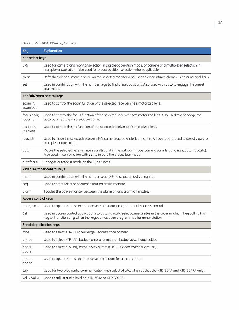
Table 1. KTD-304A/304RA key functions
Key Explanation
Site select keys
0–9 Used for camera and monitor selection in Digiplex operation mode, or camera and multiplexer selection in multiplexer operation. Also used for preset position selection when applicable.
clear Refreshes alphanumeric display on the selected monitor. Also used to clear infinite alarms using numerical keys.
set Used in combination with the number keys to find preset positions. Also used with auto to engage the preset tour mode.
Pan/tilt/zoom control keys
zoom in, zoom out
Used to control the zoom function of the selected receiver site’s motorized lens.
focus near, focus far
Used to control the focus function of the selected receiver site’s motorized lens. Also used to disengage the autofocus feature on the CyberDome.
iris open, iris close
Used to control the iris function of the selected receiver site’s motorized lens.
joystick Used to move the selected receiver site’s camera up, down, left, or right in P/T operation. Used to select views for multiplexer operation.
auto Places the selected receiver site’s pan/tilt unit in the autopan mode (camera pans left and right automatically). Also used in combination with set to initiate the preset tour mode.
autofocus Engages autofocus mode on the CyberDome.
Video switcher control keys
mon Used in combination with the number keys (0-9) to select an active monitor.
seq Used to start selected sequence tour on active monitor.
alarm Toggles the active monitor between the alarm on and alarm off modes.
Access control keys
open, close Used to operate the selected receiver site’s door, gate, or turnstile access control.
1st Used in access control applications to automatically select camera sites in the order in which they call in. This key will function only when the keypad has been programmed for annunciation.
Special application keys
face Used to select KTR-11 Face/Badge Reader’s face camera.
badge Used to select KTR-11’s badge camera (or inserted badge view, if applicable).
door1, door2
Used to select auxiliary camera views from KTR-11’s video switcher circuitry.
open1, open2
Used to operate the selected receiver site’s door for access control.
talk Used for two-way audio communication with selected site, when applicable (KTD-304A and KTD-304RA only).
vol , vol Used to adjust audio level on KTD-304A or KTD-304RA.

KTR-11 Face/Badge ReaderInstallation Manual
18
Site programming
Refer to the decal on the inside of the KTR-11’s door for assigning the unit’s site number in the KTR-11 system.
Multiplexer function keys1
mplx Toggles the keypad between Digiplex and multiplexer view control modes.
run Selects automatic switching of videos in lower right window f current view; also used in setup of motion detection areas.
sel Used to select an active multiplexer.
zoom Toggles between a full screen view and a 2x view of the selected video, if available on the specific multiplexer.
live Used to view the live video inputs in any of the display modes; also used during setup of motion detection areas
vcr Selects VCR output for monitoring during taping or VCR input for viewing during playback. Also used in setup of motion detection areas.
full Used by some multiplexer types to restore full view.
view Toggles between selected views.
fn Reserved for future development.
1. The mutiplexer keys may function differently, or not at all, on some models of multiplexers.
Table 1. KTD-304A/304RA key functions (continued)
Key Explanation

19
Contacting technical supportFor assistance installing, operating, maintaining, and troubleshooting this product, refer to this document and any other documentation provided. If you still have questions, you may contact technical support during normal business hours (Monday through Friday, excluding holidays, between 5 a.m. and 5 p.m. Pacific Time).
Note: Be ready at the equipment before calling for technical support.
Online publication library
Another great resource for assistance with your GE Security products is our online publication library, available to all of our customers on our website. To access our publication library, go to our website at the following location:
http://www.gesecurity.com
In the Tools area at the top, click the Publication Library link. After you register and log on, you may search through our online library for the documentation you need.1
Table 2. Sales and support contact information
Sales Technical support
Phone: Toll-free: 888.GESECURity (888.437.3287) in the US, including Alaska and Hawaii; Puerto Rico; Canada. Outside the toll-free area: 503.885.5700.
E-mail [email protected] [email protected]
Fax 800.483.2495 541.752.9096 (available 24 hours a day)
1. Many GE Security documents are provided as PDFs (portable document format). To read these documents, you will need Adobe Acrobat Reader, which can be downloaded free from Adobe’s website at www.adobe.com.

KTR-11 Face/Badge ReaderInstallation Manual
20