Embed Size (px)
Citation preview
ÄKTA™ avantOperating InstructionsOriginal instructions
Table of Contents41 Introduction ..........................................................................................................51.1 About this manual ................................................................................................................................61.2 Important user information .............................................................................................................81.3 Regulatory information ......................................................................................................................
121.4 Associated Documentation .............................................................................................................
142 Safety Instructions ...............................................................................................152.1 Safety Precautions ...............................................................................................................................242.2 Labels .........................................................................................................................................................272.3 Emergency procedures ......................................................................................................................302.4 Recycling information .........................................................................................................................312.5 Declaration of Hazardous Substances (DoHS) ........................................................................
333 System description ..............................................................................................343.1 ÄKTA avant instrument overview ..................................................................................................433.2 UNICORN software ...............................................................................................................................443.2.1 UNICORN software overview ....................................................................................................463.2.2 The System Control module ......................................................................................................
484 Installation ............................................................................................................494.1 Site preparation .....................................................................................................................................504.1.1 Delivery and storage ....................................................................................................................524.1.2 Room requirements ......................................................................................................................564.1.3 Site environment ............................................................................................................................574.1.4 Power requirements .....................................................................................................................594.1.5 Computer requirements ..............................................................................................................614.1.6 Required materials ........................................................................................................................644.2 Hardware installation .........................................................................................................................654.2.1 Install the computer equipment ..............................................................................................664.2.2 Connect the system units ...........................................................................................................704.2.3 Prepare waste tubing ...................................................................................................................734.2.4 Install the Barcode Scanner 2-D and the pH electrode .................................................744.2.5 Prepare the pump rinsing system ...........................................................................................774.2.6 Start the instrument and the computer ...............................................................................784.3 Software installation ...........................................................................................................................794.4 Start UNICORN and connect to system ......................................................................................824.5 Prime inlets and purge pump heads ...........................................................................................834.5.1 Prime buffer inlets and purge system pumps ...................................................................904.5.2 Prime sample inlets and purge Sample Pump ..................................................................954.5.3 Prime Q inlets ...................................................................................................................................
1004.6 Performance tests ................................................................................................................................
1015 Prepare the system for a run .............................................................................1025.1 Before you prepare the system ......................................................................................................1045.2 Prepare the flowpath ..........................................................................................................................
2 ÄKTA avant Operating Instructions 29-1015-56 AA
Table of Contents

1095.3 Prime buffer inlets and purge system pumps .........................................................................1105.4 Connect a column ................................................................................................................................1155.5 Set pressure alarms .............................................................................................................................1175.6 Calibrate the pH monitor ..................................................................................................................1195.7 Prepare the built-in fraction collector .........................................................................................1255.8 Prepare for a run at cold temperature .......................................................................................
1266 Run a method ........................................................................................................1276.1 Before you start .....................................................................................................................................1306.2 Applying the sample ............................................................................................................................1336.3 Start a method run ..............................................................................................................................1396.4 Monitor the run ......................................................................................................................................1426.5 After run procedures ...........................................................................................................................
1457 Maintenance .........................................................................................................1467.1 Maintenance program .......................................................................................................................
1497.2 Replace pump piston seal, O-rings, and rinse membrane of Pump P9 or Pump
P9H ..............................................................................................................................................................1607.3 Replace pump piston seal, O-ring, and rinse membrane of Pump P9-S ....................1687.4 Replace pump pistons ........................................................................................................................1707.5 Clean pump head check valves .....................................................................................................
1738 Reference Information ........................................................................................1748.1 System specifications .........................................................................................................................1768.2 Chemical resistance guide ...............................................................................................................1818.3 Check and change the Node ID of a module ..........................................................................
185Index .......................................................................................................................
ÄKTA avant Operating Instructions 29-1015-56 AA 3
Table of Contents
1 Introduction
About this chapterThis chapter contains important user information, descriptions of safety notices, regula-tory information, intended use of the ÄKTA avant instrument, and lists of associateddocumentation.
See pageSection
51.1 About this manual
61.2 Important user information
81.3 Regulatory information
121.4 Associated Documentation
4 ÄKTA avant Operating Instructions 29-1015-56 AA
1 Introduction
1.1 About this manual
Purpose of this manualThe Operating Instructions provide you with the instructions needed to install, operateand maintain the product in a safe way.
Typographical conventionsSoftware items are identified in the text by bold italic text. A colon separates items in agroup, thus Flowpath:Injection valve refers to the Injection valve item in the Flowpathgroup.
Hardware items are identified in the text by bold text (for example, the Power button).
ÄKTA avant Operating Instructions 29-1015-56 AA 5
1 Introduction1.1 About this manual
1.2 Important user information
Read this before operating theproduct
All users must read the entire Operating Instructions before installing, operating ormaintaining the product.
Always keep the Operating Instructions at hand when operating the product.
Do not operate the product in any other way than described in the user documentation.If you do, you may be exposed to hazards that can lead to personal injury and you maycause damage to the equipment.
Intended use of the productÄKTA avant is a liquid chromatography system intended for method and process devel-opment in purification of biomolecules. The system can be used to screen for optimalchoice of columns, media and running parameters to purify selected proteins.
The ÄKTA avant system is intended for research use only, and shall not be used in anyclinical procedures, or for diagnostic procedures.
PrerequisitesIn order to follow this manual and use the system in the manner it is intended, it is im-portant that:
• You have a general understanding of how the computer and Microsoft® Windows®work.
• You understand the concepts of liquid chromatography.
• You have read and understood the Safety instructions chapter in this manual.
• A user account has been created according to the UNICORN™ Administration andTechnical Manual.
6 ÄKTA avant Operating Instructions 29-1015-56 AA
1 Introduction1.2 Important user information
Safety noticesThis user documentation contains safety notices (WARNING, CAUTION, and NOTICE)concerning the safe use of the product. See definitions below.
WARNINGWARNING indicates a hazardous situation which, if not avoided,could result in death or serious injury. It is important not to proceeduntil all stated conditions are met and clearly understood.
CAUTIONCAUTION indicates a hazardous situation which, if not avoided,could result in minor or moderate injury. It is important not to pro-ceed until all stated conditions are met and clearly understood.
NOTICENOTICE indicates instructions that must be followed to avoiddamage to the product or other equipment.
Notes and tipsA note is used to indicate information that is important for trouble-free andoptimal use of the product.
Note:
A tip contains useful information that can improve or optimize your procedures.Tip:
ÄKTA avant Operating Instructions 29-1015-56 AA 7
1 Introduction1.2 Important user information

1.3 Regulatory information
IntroductionThis section lists the directives and standards that are fulfilled by the ÄKTA avant instru-ment.
Manufacturing informationThe table below summarizes the required manufacturing information. For further infor-mation, see the EU Declaration of Conformity (DoC) document.
ContentRequirement
GE Healthcare Bio-Sciences AB,Name and address of manufacturer
Björkgatan 30, SE 751 84 Uppsala, Sweden
Conformity with EU DirectivesThis product complies with the European directives listed in the table, by fulfilling thecorresponding harmonized standards.
A copy of the EU Declaration of Conformity is included in the documentation package.
TitleDirective
Machinery Directive (MD)2006/42/EC
Electromagnetic Compatibility (EMC) Directive2004/108/EC
Low Voltage Directive (LVD)2006/95/EC
Radio Equipment and Telecommunications TerminalEquipment (R&TTE) Directive.
1999/5/EC
8 ÄKTA avant Operating Instructions 29-1015-56 AA
1 Introduction1.3 Regulatory information
CE marking
The CE marking and the corresponding EU Declaration of Conformity is valid for the in-strument when it is:
• used as a stand-alone unit, or
• connected to other products recommended or described in the user documentation,and
• used in the same state as it was delivered from GE, except for alterations describedin the user documentation.
International standardsThis product fulfills the requirements of the following standards:
NotesDescriptionStandard
EN ISO standard is har-monized with EU direc-tive 2006/42/EC
Safety of machinery. General princi-ples for design. Risk assessment andrisk reduction.
EN ISO 12100
EN standard is harmo-nized with EU directive2006/95/EC
Safety requirements for electricalequipment for measurement, control,and laboratory use.
EN/IEC 61010-1,UL 61010-1,CAN/CSA C22.2No. 61010-1
EN standard is harmo-nized with EU directive2004/108/EC
Electrical equipment for measure-ment, control and laboratory use -EMC requirements
EN/IEC 61326-1
(Emission accord-ing to CISPR 11,Group 1, class A)
EN standard is harmo-nized with EU directives1999/5/EC
Electromagnetic compatibility andRadio spectrum Matters (ERM); Elec-troMagnetic Compatibility (EMC)standard for radio equipment andservices.
ETSI EN 301 489-3
ÄKTA avant Operating Instructions 29-1015-56 AA 9
1 Introduction1.3 Regulatory information
NotesDescriptionStandard
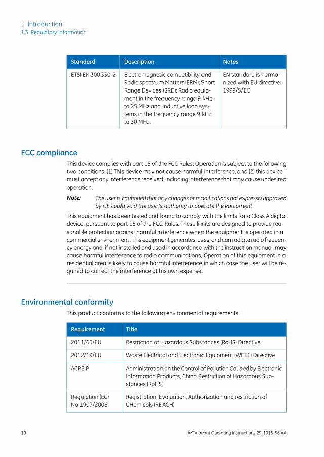
EN standard is harmo-nized with EU directive1999/5/EC
Electromagnetic compatibility andRadio spectrum Matters (ERM); ShortRange Devices (SRD); Radio equip-ment in the frequency range 9 kHzto 25 MHz and inductive loop sys-tems in the frequency range 9 kHzto 30 MHz.
ETSI EN 300 330-2
FCC complianceThis device complies with part 15 of the FCC Rules. Operation is subject to the followingtwo conditions: (1) This device may not cause harmful interference, and (2) this devicemust accept any interference received, including interference that may cause undesiredoperation.
The user is cautioned that any changes ormodifications not expressly approvedby GE could void the user’s authority to operate the equipment.
Note:
This equipment has been tested and found to comply with the limits for a Class A digitaldevice, pursuant to part 15 of the FCC Rules. These limits are designed to provide rea-sonable protection against harmful interference when the equipment is operated in acommercial environment. This equipment generates, uses, and can radiate radio frequen-cy energy and, if not installed and used in accordance with the instruction manual, maycause harmful interference to radio communications. Operation of this equipment in aresidential area is likely to cause harmful interference in which case the user will be re-quired to correct the interference at his own expense.
Environmental conformityThis product conforms to the following environmental requirements.
TitleRequirement
Restriction of Hazardous Substances (RoHS) Directive2011/65/EU
Waste Electrical and Electronic Equipment (WEEE) Directive2012/19/EU
Administration on the Control of Pollution Caused by ElectronicInformation Products, China Restriction of Hazardous Sub-stances (RoHS)
ACPEIP
Registration, Evaluation, Authorization and restriction ofCHemicals (REACH)
Regulation (EC)No 1907/2006
10 ÄKTA avant Operating Instructions 29-1015-56 AA
1 Introduction1.3 Regulatory information
Regulatory compliance ofconnected equipment
Any equipment connected to ÄKTA avant should meet the safety requirements of EN/IEC61010-1, or relevant harmonized standards. Within EU, connected equipment must beCE marked.
ÄKTA avant Operating Instructions 29-1015-56 AA 11
1 Introduction1.3 Regulatory information
1.4 Associated Documentation
IntroductionThis section describes the user documentation that is delivered with the ÄKTA avant in-strument.
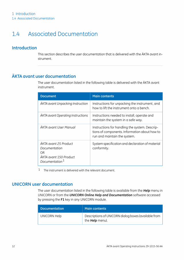
ÄKTA avant user documentationThe user documentation listed in the following table is delivered with the ÄKTA avantinstrument.
Main contentsDocument
Instructions for unpacking the instrument, andhow to lift the instrument onto a bench.
ÄKTA avant Unpacking Instruction
Instructions needed to install, operate andmaintain the system in a safe way.
ÄKTA avant Operating Instructions
Instructions for handling the system. Descrip-tions of components. Information about how torun and maintain the system.
ÄKTA avant User Manual
System specification and declaration of materialconformity.
ÄKTA avant 25 ProductDocumentationORÄKTA avant 150 ProductDocumentation1
1 The instrument is delivered with the relevant document.
UNICORN user documentationThe user documentation listed in the following table is available from the Help menu inUNICORN or from the UNICORN Online Help and Documentation software accessedby pressing the F1 key in any UNICORN module.
Main contentsDocumentation
Descriptions of UNICORN dialog boxes (available fromthe Help menu).
UNICORN Help
12 ÄKTA avant Operating Instructions 29-1015-56 AA
1 Introduction1.4 Associated Documentation
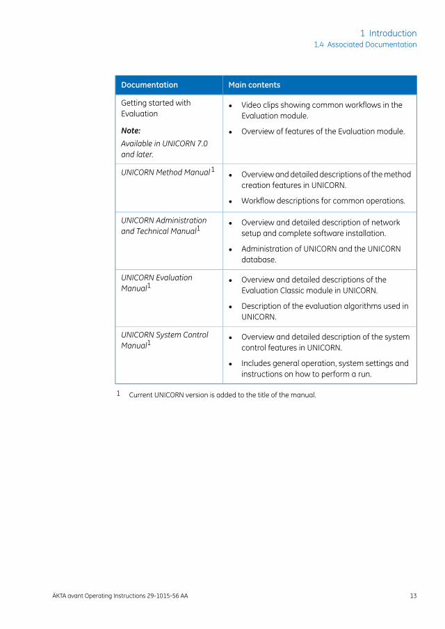
Main contentsDocumentation
• Video clips showing common workflows in theEvaluation module.
• Overview of features of the Evaluation module.
Getting started withEvaluation
Note:
Available in UNICORN 7.0and later.
• Overview and detailed descriptions of the methodcreation features in UNICORN.
• Workflow descriptions for common operations.
UNICORN Method Manual1
• Overview and detailed description of networksetup and complete software installation.
• Administration of UNICORN and the UNICORNdatabase.
UNICORN Administrationand Technical Manual1
• Overview and detailed descriptions of theEvaluation Classic module in UNICORN.
• Description of the evaluation algorithms used inUNICORN.
UNICORN EvaluationManual1
• Overview and detailed description of the systemcontrol features in UNICORN.
• Includes general operation, system settings andinstructions on how to perform a run.
UNICORN System ControlManual1
1 Current UNICORN version is added to the title of the manual.
ÄKTA avant Operating Instructions 29-1015-56 AA 13
1 Introduction1.4 Associated Documentation
2 Safety Instructions
About this chapterThis chapter describes safety precautions and emergency shutdown procedures for theproduct. The labels on the system and information regarding recycling are also described.
Important
WARNINGBefore installing, operating ormaintaining the product, all usersmust read and understand the entire contents of this chapterto become aware of the hazards involved.
In this chapter
See pageSection
152.1 Safety Precautions
242.2 Labels
272.3 Emergency procedures
302.4 Recycling information
312.5 Declaration of Hazardous Substances (DoHS)
14 ÄKTA avant Operating Instructions 29-1015-56 AA
2 Safety Instructions
2.1 Safety Precautions
IntroductionThe safety precautions in this section are grouped in the following categories:
• General precautions, on page 15
• Flammable liquids and explosive environment, on page 16
• Personal protection, on page 17
• Installing and moving, on page 18
• System operation, on page 20
• Maintenance, on page 22
General precautions
WARNINGRisk assessment. Perform a risk assessment for any risks due tothe process or process environment. Evaluate the effects the useof the product and the operational processes may have on theclassification of the hazardous area. The process might cause thearea to increase or the zone classification to change. Implementthe risk reduction measures needed, including use of personalprotective equipment.
WARNINGAlways follow these General precautions to avoid injury whenusing the ÄKTA avant instrument.
• Do not operate the ÄKTA avant instrument in any other waythan described in the ÄKTA avant and UNICORN manuals.
• Only properly trained personnel may perform operation anduser maintenance of the product.
• Before connecting to a column, read the instructions for useof the column. To avoid exposing the column to excessivepressure, make sure that the pressure limit is set to the speci-fied maximum pressure for the column.
ÄKTA avant Operating Instructions 29-1015-56 AA 15
2 Safety Instructions2.1 Safety Precautions

WARNING• Do not use any accessories not supplied or recommended by
GE.
• Do not use ÄKTA avant if it is not working properly, or if it hassuffered any damage, for example:
- damage to the power cord or its plug
- damage caused by dropping the equipment
- damage caused by splashing liquid onto it
NOTICEAvoid condensation. If ÄKTA avant is kept in a cold room, coldcabinet or similar, keep it switched on in order to avoid condensa-tion.
Flammable liquids and explosiveenvironment
WARNINGWhen using flammable liquids with the ÄKTA avant system,follow these precautions to avoid any risk of fire or explosion.
• Fire Hazard. Before starting the system, make sure that thereis no leakage.
• Explosion hazard. To avoid building up an explosive atmo-sphere when using flammable liquids, make sure that the roomventilation meets the local requirements.
• Fraction collector. Do not fractionate flammable liquids in thebuilt-in fraction collector. When running RPC methods, collectfractions through the outlet valve or the optional externalFraction Collector F9-R.
16 ÄKTA avant Operating Instructions 29-1015-56 AA
2 Safety Instructions2.1 Safety Precautions
WARNING• RPC runswith 100%acetonitrile and systempressure above
5 MPa (50 bar) in ÄKTA avant 25. Always replace the greenPEEK tubing between the used system pump and the pumppressure monitor with orange PEEK tubing, i.d. 0.5 mm, beforerunning RPC with 100% acetonitrile. Set the system pressurealarm to 10 MPa (100 bar).
• RPC runs with 100% acetonitrile in ÄKTA avant 150. Alwaysreplace the beige PEEK tubing between the used system pumpand the pump pressure monitor before running RPC with 100%acetonitrile. Replace it with green PEEK tubing, i.d. 0.75 mm.
Personal protection
WARNINGTo avoid injurywhenworkingwith the ÄKTA avant system, takethe following measures for personal protection.
• Always use appropriate Personal Protective Equipment (PPE)during operation and maintenance of this product.
• Hazardous substances and biological agents. When usinghazardous chemical and biological agents, take all suitableprotective measures, such as wearing protective glasses andgloves resistant to the substances used. Follow local and/ornational regulations for safe operation and maintenance ofÄKTA avant.
• Spread of biological agents. The operator must take all nec-essary actions to avoid spreading hazardous biological agents.The facility must comply with the national code of practice forbiosafety.
• High pressure. The product operates under high pressure.Wear protective glasses and other required Personal ProtectiveEquipment (PPE) at all times.
ÄKTA avant Operating Instructions 29-1015-56 AA 17
2 Safety Instructions2.1 Safety Precautions
CAUTIONTo avoid hazardous situations when working with the ÄKTAavant system, take the followingmeasures for personal protec-tion.
• Always use appropriate personal protective equipment whendecommissioning the equipment.
• Close doors. To minimize the risk of exposure to hazardouschemicals and pressurized liquids, always close the foldabledoor and the pump cover before starting a run.
• Cut injuries. The tubing cutter is very sharp and must behandled with care to avoid injuries.
Installing and moving
WARNINGTo avoid injury when installing and moving the ÄKTA avantsystem, take the following measures for personal protection.
• Move transport crates. Make sure that the forklift has thecapacity to safely lift the crate weight. Make sure that the crateis properly balanced so that it will not accidentally tip whenmoved.
• Heavy object. The ÄKTA avant instrument weighs about 116kg. Use proper lifting equipment, or use four or more personswhen moving the instrument. All lifting and moving must beperformed in accordance with local regulations.
• Moving the product horizontally. Three people are requiredto move the product horizontally.
• Supply voltage.Before connecting the power cord, make surethat the supply voltage at the wall outlet corresponds to themarking on the instrument.
• Protective ground. The product must always be connectedto a grounded power outlet.
• Power cord. Only use power cords with approved plugs deliv-ered or approved by GE.
18 ÄKTA avant Operating Instructions 29-1015-56 AA
2 Safety Instructions2.1 Safety Precautions
WARNING• Access to power switch and power cord with plug. Do not
block access to the power switch and power cord. The powerswitch must always be easy to access. The power cord withplug must always be easy to disconnect.
• Installing the computer. The computer must be installed andused according to the instructions provided by the manufac-turer of the computer.
NOTICE
Toavoid damage to the instrumentwhen installing andmovingthe ÄKTA avant system, take the following measures.
• Make sure that the waste vessels will hold all the producedvolume of the run. For ÄKTA avant 25, a suitable waste vesselshould typically have a volume of 2 to 10 liters. For ÄKTA avant150, a waste vessel should have a volume of 40 liters.
• The maximum level of the waste vessel for the waste tubingfrom the valves must be lower than 30 cm above the lab bench.
• The maximum level of the waste vessel for the waste tubingfrom the fraction collector and the buffer tray must be lowerthan the bench height.
• Vents on the ÄKTA avant instrument. To ensure adequateventilation, keep papers and other objects away from the ventsof the instrument.
• Disconnect power. To prevent equipment damage, alwaysdisconnect the power from the product before an instrumentmodule is removed or installed, or a cable is connected ordisconnected.
• Misuse of UniNet-9 connectors. TheUniNet-9 connectors atthe rear panel should not be mistaken for Firewire connectors.Do not connect any external equipment to the UniNet-9 con-nectors other than instrument modules designed for ÄKTAavant. SeeÄKTAavant UserManual. Do not disconnect or movethe UniNet-9 bus cable.
ÄKTA avant Operating Instructions 29-1015-56 AA 19
2 Safety Instructions2.1 Safety Precautions
System operation
WARNINGToavoid personal injurywhenoperating theÄKTAavant system,follow these instructions.
• Rotating the instrument. Make sure that there is always atleast 20 cm of free space around the ÄKTA avant instrumentto allow for sufficient ventilation and rotation on the swivelfoot. When rotating the instrument, take care not to stretch orsqueeze tubing or cables. A disconnected cable may causepower interruption or network interruption. Stretched tubingmay cause bottles to fall, resulting in liquid spillage and shat-tered glass. Squeezed tubing may cause increase in pressure,or block liquid flow. To avoid the risk of knocking over bottles,always place bottles on the buffer tray, and close the doorsbefore rotating the instrument.
• Fasten bottles and cassettes. Always fasten bottles and cas-settes to the rails at the front and side panel. Use appropriateholders for bottles. Shattered glass from falling bottles maycause injury. Spilled liquid may cause fire hazard and personalinjury.
• Electrical shock hazard after spillage. If there is a risk thatlarge volumes of spilled liquid may penetrate the casing of theinstrument, immediately switch off the instrument, disconnectthe power cord, and contact an authorized service engineer.
• Moving parts in fraction collector. Do not open the built-infraction collector door when the instrument is running.
• Using a Superloop. After loading a Superloop, always plug theSyr port on the injection valve with a stop plug. With a Super-loop connected to the valve, an over-pressure may be createdduring injection.
• Over-pressure.Never block the outlet tubing with, for instance,stop plugs, since this will create over-pressure and might resultin injury.
• Hazardous chemicals during run. When using hazardouschemicals, run System CIP and Column CIP to flush the entiresystem tubing with distilled water, before service and mainte-nance.
20 ÄKTA avant Operating Instructions 29-1015-56 AA
2 Safety Instructions2.1 Safety Precautions
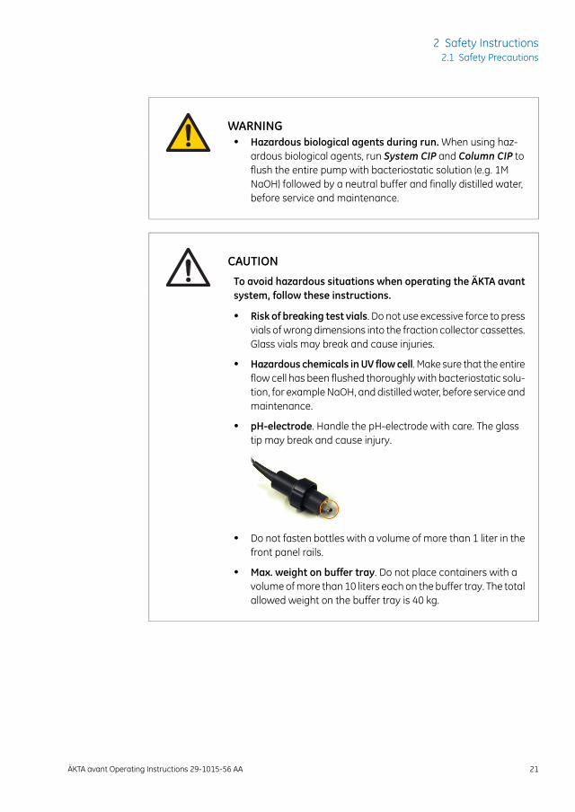
WARNING• Hazardous biological agents during run. When using haz-
ardous biological agents, run System CIP and Column CIP toflush the entire pump with bacteriostatic solution (e.g. 1MNaOH) followed by a neutral buffer and finally distilled water,before service and maintenance.
CAUTIONTo avoid hazardous situations when operating the ÄKTA avantsystem, follow these instructions.
• Risk of breaking test vials. Do not use excessive force to pressvials of wrong dimensions into the fraction collector cassettes.Glass vials may break and cause injuries.
• Hazardous chemicals inUV flowcell. Make sure that the entireflow cell has been flushed thoroughly with bacteriostatic solu-tion, for example NaOH, and distilled water, before service andmaintenance.
• pH-electrode. Handle the pH-electrode with care. The glasstip may break and cause injury.
• Do not fasten bottles with a volume of more than 1 liter in thefront panel rails.
• Max. weight on buffer tray. Do not place containers with avolume of more than 10 liters each on the buffer tray. The totalallowed weight on the buffer tray is 40 kg.
ÄKTA avant Operating Instructions 29-1015-56 AA 21
2 Safety Instructions2.1 Safety Precautions
NOTICE
To avoid damage to the ÄKTA avant instrument or otherequipmentwhenoperating the instrument, follow these instruc-tions.
• Keep UV flow cell clean. Do not allow solutions containingdissolved salts, proteins or other solid solutes to dry out in theflow cell. Do not allow particles to enter the flow cell, as dam-age to the flow cell may occur.
• Glass tube splinter. Make sure to set the sample pressurebelow the maximum pressure of the Superloop before execut-ing a flow in the Manual instructions dialog box when theSuperloop is connected.
• Avoid condensation. If ÄKTA avant is kept in a cold room, coldcabinet or similar, keep it switched on in order to avoid conden-sation.
• Avoid overheating. If ÄKTA avant is kept in a cold cabinet andthe cold cabinet is switched off, make sure to switch off ÄKTAavant and keep the cold cabinet open to avoid overheating.
• Place the computer in room temperature. If the ÄKTA avantinstrument is placed in a cold room, use a cold room compat-ible computer or place the computer outside the cold roomand use the Ethernet cable delivered with the instrument toconnect to the computer.
• UV and conductivity flow cells on the high pressure side.When placing UV and/or conductivity flow cells on the highpressure side of the column, the UV flow cell has a maximumpressure limit of 2 MPa (20 bar) and the conductivity flow cellhas a maximum pressure limit of 5 MPa (50 bar).
Maintenance
WARNINGTo avoid personal injury when performingmaintenance on theÄKTA avant instrument, follow these instructions.
22 ÄKTA avant Operating Instructions 29-1015-56 AA
2 Safety Instructions2.1 Safety Precautions
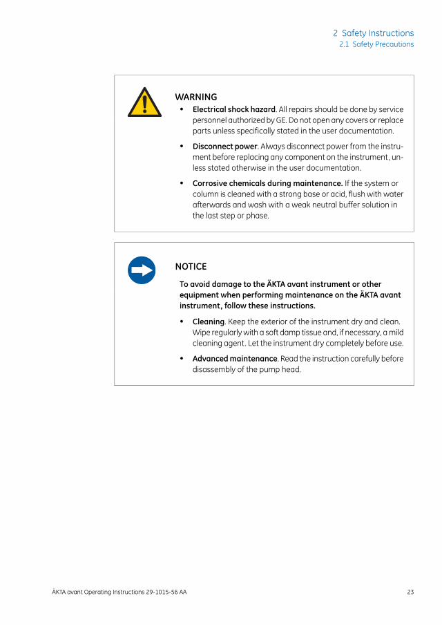
WARNING• Electrical shock hazard. All repairs should be done by service
personnel authorized by GE. Do not open any covers or replaceparts unless specifically stated in the user documentation.
• Disconnect power. Always disconnect power from the instru-ment before replacing any component on the instrument, un-less stated otherwise in the user documentation.
• Corrosive chemicals during maintenance. If the system orcolumn is cleaned with a strong base or acid, flush with waterafterwards and wash with a weak neutral buffer solution inthe last step or phase.
NOTICE
To avoid damage to the ÄKTA avant instrument or otherequipment when performing maintenance on the ÄKTA avantinstrument, follow these instructions.
• Cleaning. Keep the exterior of the instrument dry and clean.Wipe regularly with a soft damp tissue and, if necessary, a mildcleaning agent. Let the instrument dry completely before use.
• Advancedmaintenance. Read the instruction carefully beforedisassembly of the pump head.
ÄKTA avant Operating Instructions 29-1015-56 AA 23
2 Safety Instructions2.1 Safety Precautions
2.2 Labels
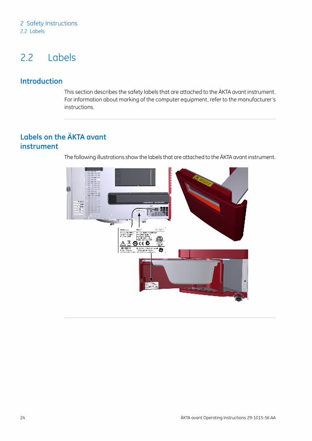
IntroductionThis section describes the safety labels that are attached to the ÄKTA avant instrument.For information about marking of the computer equipment, refer to the manufacturer’sinstructions.
Labels on the ÄKTA avantinstrument
The following illustrations show the labels that are attached to the ÄKTA avant instrument.
24 ÄKTA avant Operating Instructions 29-1015-56 AA
2 Safety Instructions2.2 Labels
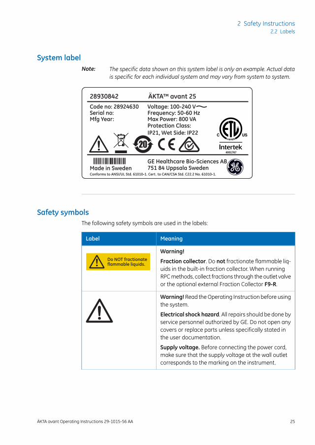
System labelThe specific data shown on this system label is only an example. Actual datais specific for each individual system and may vary from system to system.
Note:
28930842 ÄKTA™ avant 25
Code no: 28924630Serial no: Mfg Year:
Voltage: 100-240 VFrequency: 50-60 HzMax Power: 800 VA
Made in SwedenGE Healthcare Bio-Sciences AB751 84 Uppsala Sweden
Protection Class:IP21, Wet Side: IP22
Conforms to ANSI/UL Std. 61010-1. Cert. to CAN/CSA Std. C22.2 No. 61010-1.
4001767
Safety symbolsThe following safety symbols are used in the labels:
MeaningLabel
Warning!Do NOT fractionateflammable liquids. Fraction collector. Do not fractionate flammable liq-
uids in the built-in fraction collector. When runningRPC methods, collect fractions through the outlet valveor the optional external Fraction Collector F9-R.
Warning!Read the Operating Instruction before usingthe system.
Electrical shock hazard. All repairs should be done byservice personnel authorized by GE. Do not open anycovers or replace parts unless specifically stated inthe user documentation.
Supply voltage. Before connecting the power cord,make sure that the supply voltage at the wall outletcorresponds to the marking on the instrument.
ÄKTA avant Operating Instructions 29-1015-56 AA 25
2 Safety Instructions2.2 Labels
MeaningLabel
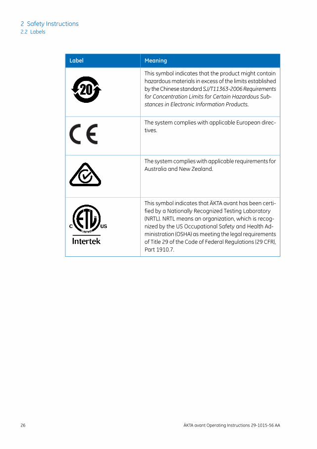
This symbol indicates that the product might containhazardous materials in excess of the limits establishedby the Chinese standardSJ/T11363-2006Requirementsfor Concentration Limits for Certain Hazardous Sub-stances in Electronic Information Products.
The system complies with applicable European direc-tives.
The system complies with applicable requirements forAustralia and New Zealand.
This symbol indicates that ÄKTA avant has been certi-fied by a Nationally Recognized Testing Laboratory(NRTL). NRTL means an organization, which is recog-nized by the US Occupational Safety and Health Ad-ministration (OSHA) as meeting the legal requirementsof Title 29 of the Code of Federal Regulations (29 CFR),Part 1910.7.
26 ÄKTA avant Operating Instructions 29-1015-56 AA
2 Safety Instructions2.2 Labels
2.3 Emergency procedures
IntroductionThis section describes how to perform an emergency shutdown of the ÄKTA avant instru-ment, including connected equipment. This section also describes the results in the eventof power failure or network interruption.
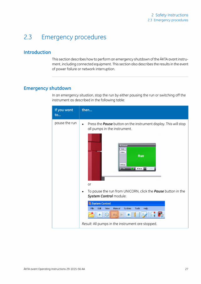
Emergency shutdownIn an emergency situation, stop the run by either pausing the run or switching off theinstrument as described in the following table:
then...If you wantto...
• Press the Pause button on the instrument display. This will stopall pumps in the instrument.
or
• To pause the run from UNICORN, click the Pause button in theSystem Control module:
Result: All pumps in the instrument are stopped.
pause the run
ÄKTA avant Operating Instructions 29-1015-56 AA 27
2 Safety Instructions2.3 Emergency procedures
then...If you wantto...
• Push the Power switch to the O position,
or
• disconnect the power cord from the wall socket.
Result: The run is interrupted immediately.
Note:
The sample and data may be lost as a result of switching off thepower.
switch off theinstrument
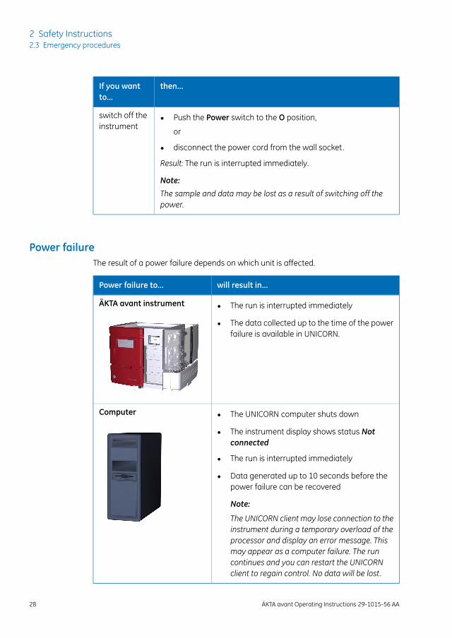
Power failureThe result of a power failure depends on which unit is affected.
will result in...Power failure to...
• The run is interrupted immediately
• The data collected up to the time of the powerfailure is available in UNICORN.
ÄKTA avant instrument
• The UNICORN computer shuts down
• The instrument display shows status Notconnected
• The run is interrupted immediately
• Data generated up to 10 seconds before thepower failure can be recovered
Note:
The UNICORN client may lose connection to theinstrument during a temporary overload of theprocessor and display an error message. Thismay appear as a computer failure. The runcontinues and you can restart the UNICORNclient to regain control. No data will be lost.
Computer
28 ÄKTA avant Operating Instructions 29-1015-56 AA
2 Safety Instructions2.3 Emergency procedures
Uninterruptible power supply(UPS)
A UPS can prevent data loss during a power failure, and allow time for a controlled shut-down of the ÄKTA avant instrument.
For UPS power requirements, see Technical specifications, on page174. Remember to alsotake into account the specifications for the computer and monitor. Refer to the manu-facturers' documentation.
Restart the instrument afteremergency shutdown or powerfailure
Follow the instructions to restart the instrument after an emergency shutdown or powerfailure.
ActionStep
Make sure that the condition that caused the emergency shutdown orpower failure is corrected.
1
If power to the instrument has been lost, restart the instrument.2
• Press the Continue button on the instrument display.
or
• Click the Continue button in the System Control module.
3
ÄKTA avant Operating Instructions 29-1015-56 AA 29
2 Safety Instructions2.3 Emergency procedures
2.4 Recycling information
IntroductionThis section describes the procedures for disposal and recycling of the ÄKTA avant in-strument.
Decommissioning and disposalof the equipment
When taking the ÄKTA avant instrument out of service:
• The equipment must be decontaminated.
• The components must be separated and recycled according to national and localenvironmental regulations
CAUTIONAlways use appropriate personal protective equipment whendecommissioning the equipment.
Disposal of electricalcomponents
Waste comprising electrical and electronic equipment must not be disposed of as un-sorted municipal waste and must be collected separately. Please contact an authorizedrepresentative of the manufacturer for information concerning the decommissioning ofequipment.
30 ÄKTA avant Operating Instructions 29-1015-56 AA
2 Safety Instructions2.4 Recycling information
2.5 Declaration of Hazardous Substances (DoHS)
根据SJ/T11364-2006《电子信息产品污染控制标识要求》特提供如下有关污染 控制方面的信息。The following product pollution control information is provided according to SJ/T11364-2006 Markingfor Control of Pollution caused by Electronic Information Products.
电子信息产品污染控制标志说明Explanation of Pollution Control Label
该标志表明本产品含有超过SJ/T11363-2006《电子信息产品中有毒有害物质的限量要求》中限量的有毒有害物质。标志中的数字为本产品的环保使用期,表明本产品在正常使用的条件下,有毒有害物质不会发生外泄或突变,用户使用本产品不会对环境造成严重污染或对其人身、财产造成严重损害的期限。单位为年。为保证所申明的环保使用期限,应按产品手册中所规定的环境条件和方法进行正常使用,并严格遵守产品维修手册中规定的期维修和保养要求。产品中的消耗件和某些零部件可能有其单独的环保使用期限标志,并且其环保使用期限有可能比整个产品本身的环保使用期限短。应到期按产品维修程序更换那些消耗件和零部件,以保证所申明的整个产品的环保使用期限。本产品在使用寿命结束时不可作为普通生活垃圾处理,应被单独收集妥善处理。This symbol indicates the product contains hazardous materials in excess of the limitsestablished by the Chinese standard SJ/T11363-2006 Requirements for ConcentrationLimits for Certain Hazardous Substances in Electronic Information Products. Thenumber in the symbol is the Environment-friendly Use Period (EFUP), which indicatesthe period during which the toxic or hazardous substances or elements contained inelectronic information products will not leak or mutate under normal operating con-ditions so that the use of such electronic information products will not result in anysevere environmental pollution, any bodily injury or damage to any assets. The unitof the period is “Year”.
In order to maintain the declared EFUP, the product shall be operated normally ac-cording to the instructions and environmental conditions as defined in the productmanual, and periodic maintenance schedules specified in Product Maintenance Pro-cedures shall be followed strictly.
Consumables or certain parts may have their own label with an EFUP value less thanthe product. Periodic replacement of those consumables or parts to maintain thedeclared EFUP shall be done in accordance with the Product Maintenance Procedures.
This product must not be disposed of as unsorted municipal waste, and must becollected separately and handled properly after decommissioning.
ÄKTA avant Operating Instructions 29-1015-56 AA 31
2 Safety Instructions2.5 Declaration of Hazardous Substances (DoHS)
有毒有害物质或元素的名称及含量Name and Concentration of Hazardous Substances
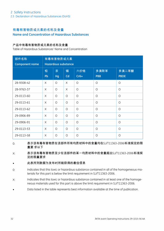
产品中有毒有害物质或元素的名称及含量Table of Hazardous Substances’ Name and Concentration
有毒有害物质或元素Hazardous substance
部件名称Component name
多溴二苯醚PBDE
多溴联苯PBB
六价铬Cr6+
镉Cd
汞Hg
铅Pb
OOOXOX28-9308-42
OOOXOX28-9763-37
OOOOOX29-0113-60
OOOOOX29-0113-61
OOOOOX29-0113-62
OOOOOX29-0906-89
OOOOOX29-0906-91
OOOOOX29-0113-53
OOOOOX29-0113-58
0: 表示该有毒有害物质在该部件所有均质材料中的含量均在SJ/T11363-2006 标准规定的限量要 求以下
X: 表示该有毒有害物质至少在该部件的某一均质材料中的含量超出SJ/T11363-2006 标准规定的限量要求
• 此表所列数据为发布时所能获得的最佳信息
0: Indicates that this toxic or hazardous substance contained in all of the homogeneous ma-terials for this part is below the limit requirement in SJ/T11363-2006.
X: Indicates that this toxic or hazardous substance contained in at least one of the homoge-neous materials used for this part is above the limit requirement in SJ/T11363-2006.
• Data listed in the table represents best information available at the time of publication.
32 ÄKTA avant Operating Instructions 29-1015-56 AA
2 Safety Instructions2.5 Declaration of Hazardous Substances (DoHS)

3 System description
About this chapterThis chapter gives an overview of the ÄKTA avant instrument, software and accessories.
In this chapterThis chapter contains the following sections:
See pageSection
343.1 ÄKTA avant instrument overview
433.2 UNICORN software
Illustration of the systemThe following illustration shows the ÄKTA avant instrument with UNICORN software in-stalled on a computer.
ÄKTA avant Operating Instructions 29-1015-56 AA 33
3 System description
3.1 ÄKTA avant instrument overview
IntroductionThis section shows an overview of the ÄKTA avant instrument. Technical details aboutthe instrument and the individual modules are found in ÄKTA avant User Manual.
Exterior designThe ÄKTA avant instrument has a modular design, with all the liquid handling modulesplaced on the exterior of the instrument. Buffer vessels are placed on the buffer tray ontop of the instrument. An instrument display is located on the front. From this side thebuilt-in fraction collector is handled, as well as the sample. The remaining modules areplaced on the right-hand side of the instrument. This side can be covered by a foldabledoor and a pump cover. By rotating the instrument using the swivel foot any side iseasily accessed.
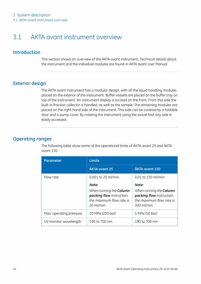
Operating rangesThe following table show some of the operational limits of ÄKTA avant 25 and ÄKTAavant 150
LimitsParameter
ÄKTA avant 150ÄKTA avant 25
0.01 to 150 ml/min
Note:
When running theColumnpacking flow instruction,the maximum flow rate is300 ml/min.
0.001 to 25 ml/min
Note:
When running theColumnpacking flow instruction,the maximum flow rate is50 ml/min.
Flow rate
5 MPa (50 bar)20 MPa (200 bar)Max. operating pressure
190 to 700 nm190 to 700 nmUV monitor wavelength
34 ÄKTA avant Operating Instructions 29-1015-56 AA
3 System description3.1 ÄKTA avant instrument overview
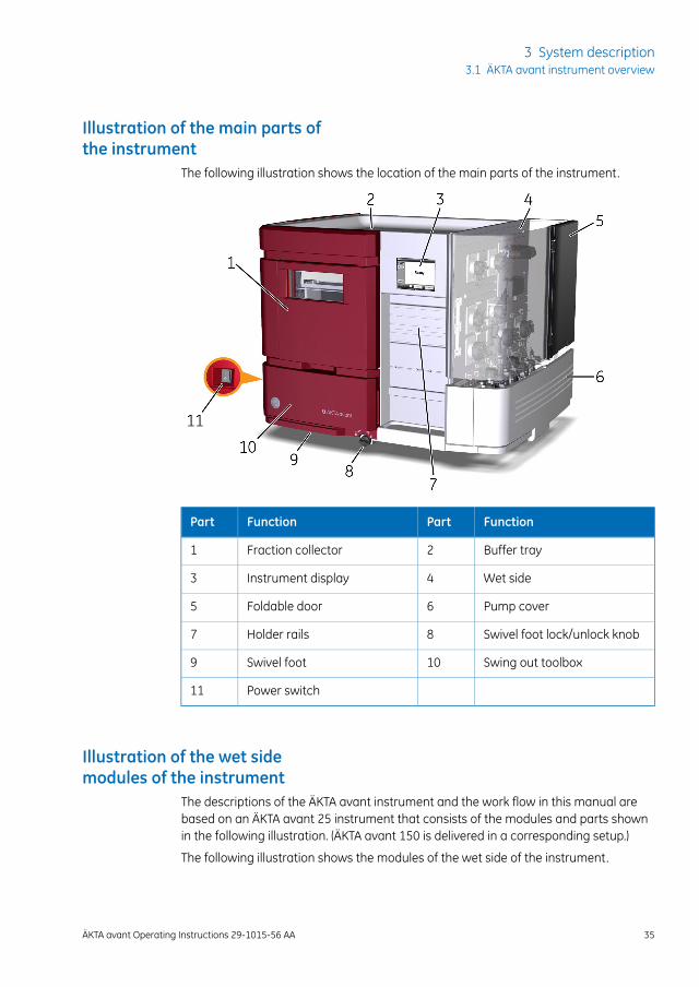
Illustration of the main parts ofthe instrument
The following illustration shows the location of the main parts of the instrument.
FunctionPartFunctionPart
Buffer tray2Fraction collector1
Wet side4Instrument display3
Pump cover6Foldable door5
Swivel foot lock/unlock knob8Holder rails7
Swing out toolbox10Swivel foot9
Power switch11
Illustration of the wet sidemodules of the instrument
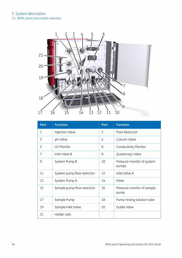
The descriptions of the ÄKTA avant instrument and the work flow in this manual arebased on an ÄKTA avant 25 instrument that consists of the modules and parts shownin the following illustration. (ÄKTA avant 150 is delivered in a corresponding setup.)
The following illustration shows the modules of the wet side of the instrument.
ÄKTA avant Operating Instructions 29-1015-56 AA 35
3 System description3.1 ÄKTA avant instrument overview
1 2 3 4 5 6
7
8
91012
18
17 16 14 13
21
20
19
1115
FunctionPartFunctionPart
Flow Restrictor2Injection Valve1
Column Valve4pH Valve3
Conductivity Monitor6UV Monitor5
Quaternary Valve8Inlet Valve B7
Pressure monitor of systempumps
10System Pump B9
Inlet Valve A12System pump flow restrictor11
Mixer14System Pump A13
Pressure monitor of samplepump
16Sample pump flow restrictor15
Pump rinsing solution tube18Sample Pump17
Outlet Valve20Sample Inlet Valve19
Holder rails21
36 ÄKTA avant Operating Instructions 29-1015-56 AA
3 System description3.1 ÄKTA avant instrument overview
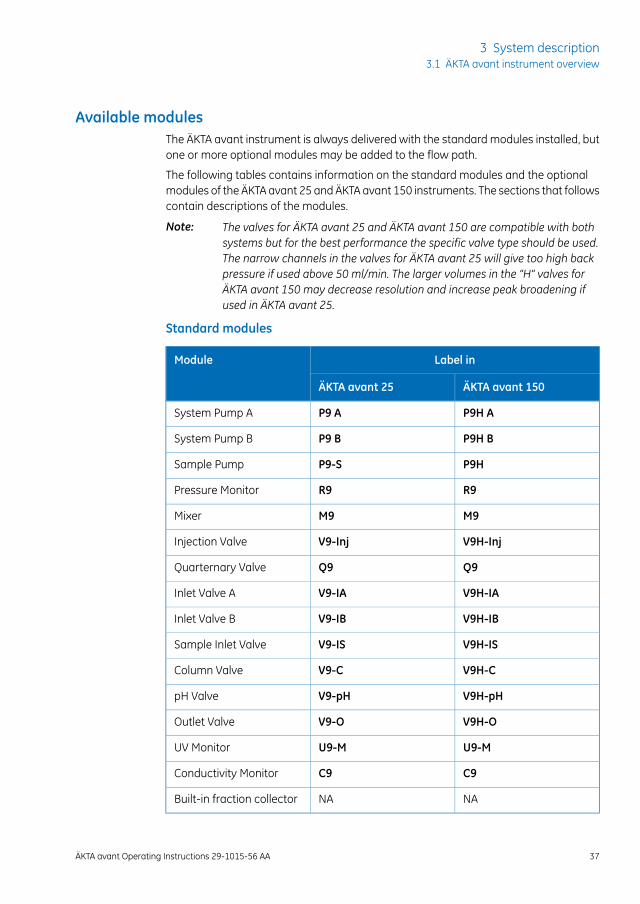
Available modulesThe ÄKTA avant instrument is always delivered with the standard modules installed, butone or more optional modules may be added to the flow path.
The following tables contains information on the standard modules and the optionalmodules of the ÄKTA avant 25 and ÄKTA avant 150 instruments. The sections that followscontain descriptions of the modules.
The valves for ÄKTA avant 25 and ÄKTA avant 150 are compatible with bothsystems but for the best performance the specific valve type should be used.The narrow channels in the valves for ÄKTA avant 25 will give too high backpressure if used above 50 ml/min. The larger volumes in the “H” valves forÄKTA avant 150 may decrease resolution and increase peak broadening ifused in ÄKTA avant 25.
Note:
Standard modules
Label inModule
ÄKTA avant 150ÄKTA avant 25
P9H AP9 ASystem Pump A
P9H BP9 BSystem Pump B
P9HP9-SSample Pump
R9R9Pressure Monitor
M9M9Mixer
V9H-InjV9-InjInjection Valve
Q9Q9Quarternary Valve
V9H-IAV9-IAInlet Valve A
V9H-IBV9-IBInlet Valve B
V9H-ISV9-ISSample Inlet Valve
V9H-CV9-CColumn Valve
V9H-pHV9-pHpH Valve
V9H-OV9-OOutlet Valve
U9-MU9-MUV Monitor
C9C9Conductivity Monitor
NANABuilt-in fraction collector
ÄKTA avant Operating Instructions 29-1015-56 AA 37
3 System description3.1 ÄKTA avant instrument overview

Optional modules
Label inModule
ÄKTA avant 150ÄKTA avant 25
V9H-A2V9-A2Second Inlet Valve A
V9H-B2V9-B2Second Inlet Valve B
V9H-IXV9-IXExtra Inlet Valve X1
V9H-IXV9-IXExtra Inlet Valve X2
V9H-S2V9-S2Second Sample Inlet Valve
V9H-VV9-VVersatile Valve
V9H-LV9-LLoop Valve
V9H-C2V9-C2Second Column Valve
V9H-O2V9-O2Second Outlet Valve
V9H-O3V9-O3Third Outlet Valve
L9-1.5L9-1.5External Air Sensor L9-1.5
L9-1.2L9-1.2External Air Sensor L9-1.2
E9E9I/O-box
U9-LU9-LSecond UV Monitor
C9C9Second ConductivityMonitor
F9-RF9-RSecond Fraction Collector
Descriptionof standardmodulesThe following modules are installed in the instrument when delivered.
DescriptionModule
Valve which allows automatic mixing of four dif-ferent solutions.
Quaternary Valve (Q9)
A high precision pump, which delivers buffer inpurification runs.
System Pump A (P9 A or P9H A)
38 ÄKTA avant Operating Instructions 29-1015-56 AA
3 System description3.1 ÄKTA avant instrument overview
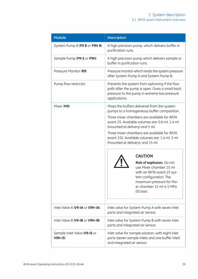
DescriptionModule
A high precision pump, which delivers buffer inpurification runs.
System Pump B (P9 B or P9H B)
A high precision pump which delivers sample orbuffer in purification runs.
Sample Pump (P9-S or P9H)
Pressure monitor which reads the system pressureafter System Pump A and System Pump B.
Pressure Monitor (R9)
Prevents the system from siphoning if the flowpath after the pump is open. Gives a small backpressure to the pump in extreme low pressureapplications.
Pump flow restrictor
Mixes the buffers delivered from the systempumps to a homogeneous buffer composition.
Mixer (M9)
Three mixer chambers are available for ÄKTAavant 25. Available volumes are: 0.6 ml, 1.4 ml(mounted at delivery) and 5 ml.
Three mixer chambers are available for ÄKTAavant 150. Available volumes are: 1.4 ml, 5 ml(mounted at delivery), and 15 ml.
CAUTIONRisk of explosion. Do notuse Mixer chamber 15 mlwith an ÄKTA avant 25 sys-tem configuration. Themaximum pressure for Mix-er chamber 15 ml is 5 MPa(50 bar).
Inlet valve for System Pump A with seven inletports and integrated air sensor.
Inlet Valve A (V9-IA or V9H-IA)
Inlet valve for System Pump B with seven inletports and integrated air sensor.
Inlet Valve B (V9-IB or V9H-IB)
Inlet valve for sample solution, with eight inletports (seven sample inlets and one buffer inlet)and integrated air sensor.
Sample Inlet Valve (V9-IS orV9H-IS)
ÄKTA avant Operating Instructions 29-1015-56 AA 39
3 System description3.1 ÄKTA avant instrument overview
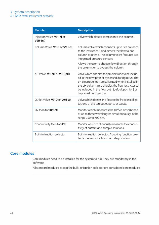
DescriptionModule
Valve which directs sample onto the column.Injection Valve (V9-Inj orV9H-Inj)
Column valve which connects up to five columnsto the instrument, and directs the flow to onecolumn at a time. The column valve features twointegrated pressure sensors.
Column Valve (V9-C or V9H-C)
Allows the user to choose flow direction throughthe column, or to bypass the column.
Valve which enables the pH electrode to be includ-ed in the flow path or bypassed during a run. ThepH electrode may be calibrated when installed inthe pH Valve. It also enables the flow restrictor tobe included in the flow path (default position) orbypassed during a run.
pH Valve (V9-pH or V9H-pH)
Valve which directs the flow to the fraction collec-tor, any of the ten outlet ports or waste.
Outlet Valve (V9-O or V9H-O)
Monitor which measures the UV/Vis absorbanceat up to three wavelengths simultaneously in therange 190 to 700 nm.
UV Monitor (U9-M)
Monitor which continuously measures the conduc-tivity of buffers and sample solutions.
Conductivity Monitor (C9)
Built-in fraction collector. A cooling function pro-tects the fractions from heat degradation.
Built-in fraction collector
Core modulesCore modules need to be installed for the system to run. They are mandatory in thesoftware.
All standard modules except the built-in fraction collector are considered core modules.
40 ÄKTA avant Operating Instructions 29-1015-56 AA
3 System description3.1 ÄKTA avant instrument overview
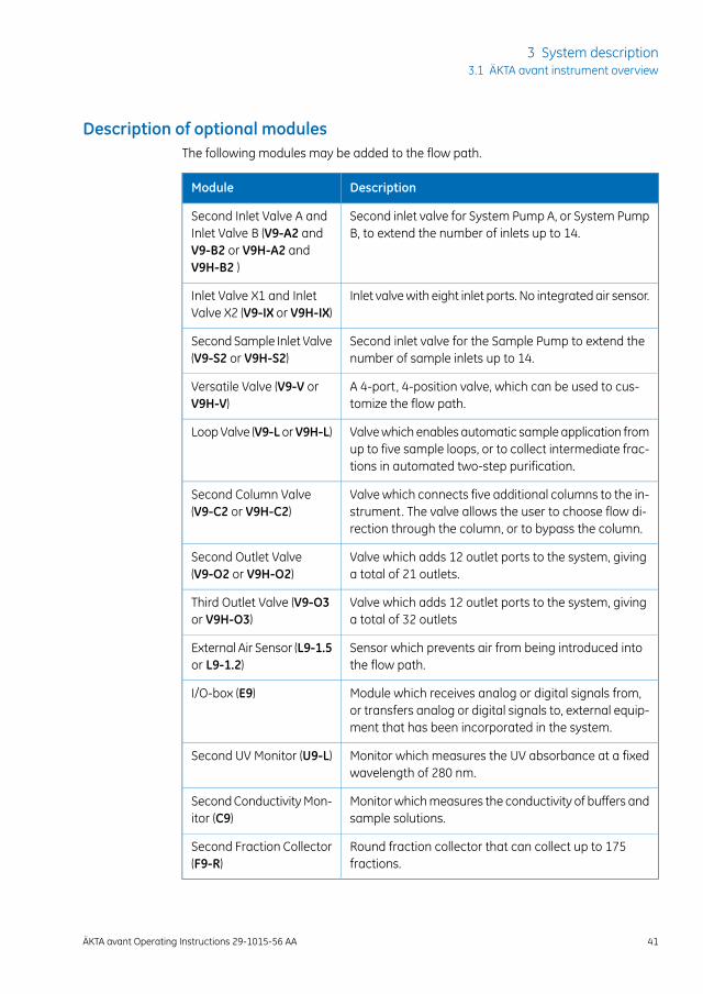
Description of optional modulesThe following modules may be added to the flow path.
DescriptionModule
Second inlet valve for System Pump A, or System PumpB, to extend the number of inlets up to 14.
Second Inlet Valve A andInlet Valve B (V9-A2 andV9-B2 or V9H-A2 andV9H-B2 )
Inlet valve with eight inlet ports. No integrated air sensor.Inlet Valve X1 and InletValve X2 (V9-IX or V9H-IX)
Second inlet valve for the Sample Pump to extend thenumber of sample inlets up to 14.
Second Sample Inlet Valve(V9-S2 or V9H-S2)
A 4-port, 4-position valve, which can be used to cus-tomize the flow path.
Versatile Valve (V9-V orV9H-V)
Valve which enables automatic sample application fromup to five sample loops, or to collect intermediate frac-tions in automated two-step purification.
Loop Valve (V9-LorV9H-L)
Valve which connects five additional columns to the in-strument. The valve allows the user to choose flow di-rection through the column, or to bypass the column.
Second Column Valve(V9-C2 or V9H-C2)
Valve which adds 12 outlet ports to the system, givinga total of 21 outlets.
Second Outlet Valve(V9-O2 or V9H-O2)
Valve which adds 12 outlet ports to the system, givinga total of 32 outlets
Third Outlet Valve (V9-O3or V9H-O3)
Sensor which prevents air from being introduced intothe flow path.
External Air Sensor (L9-1.5or L9-1.2)
Module which receives analog or digital signals from,or transfers analog or digital signals to, external equip-ment that has been incorporated in the system.
I/O-box (E9)
Monitor which measures the UV absorbance at a fixedwavelength of 280 nm.
Second UV Monitor (U9-L)
Monitor which measures the conductivity of buffers andsample solutions.
Second Conductivity Mon-itor (C9)
Round fraction collector that can collect up to 175fractions.
Second Fraction Collector(F9-R)
ÄKTA avant Operating Instructions 29-1015-56 AA 41
3 System description3.1 ÄKTA avant instrument overview
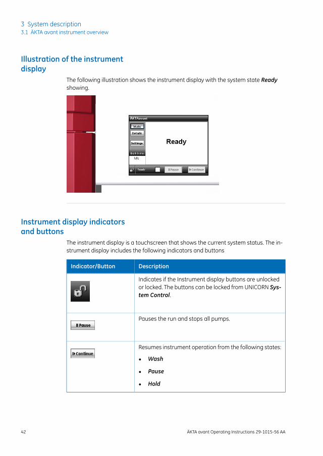
Illustration of the instrumentdisplay
The following illustration shows the instrument display with the system state Readyshowing.
Instrument display indicatorsand buttons
The instrument display is a touchscreen that shows the current system status. The in-strument display includes the following indicators and buttons
DescriptionIndicator/Button
Indicates if the Instrument display buttons are unlockedor locked. The buttons can be locked from UNICORN Sys-tem Control.
Pauses the run and stops all pumps.
Resumes instrument operation from the following states:
• Wash
• Pause
• Hold
42 ÄKTA avant Operating Instructions 29-1015-56 AA
3 System description3.1 ÄKTA avant instrument overview
3.2 UNICORN software
IntroductionThis section gives an overview of the UNICORN software. It also describes the SystemControl module.
To learn more about System Control and the other three modules Administration,Method Editor and Evaluation, see the UNICORN documentation package.
In this sectionThis chapter contains the following sections:
See pageSection
443.2.1 UNICORN software overview
463.2.2 The System Control module
ÄKTA avant Operating Instructions 29-1015-56 AA 43
3 System description3.2 UNICORN software
3.2.1 UNICORN software overview
IntroductionThis section gives a brief overview of the UNICORN software: a complete package forcontrol, supervision and evaluation of chromatography instruments and purificationruns.
From hereon, UNICORN refers to compatible versions of the software. The examplesgiven in this manual are from UNICORN 6.4.
44 ÄKTA avant Operating Instructions 29-1015-56 AA
3 System description3.2 UNICORN software3.2.1 UNICORN software overview
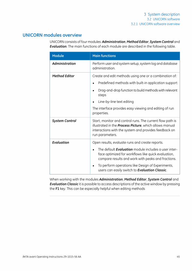
UNICORN modules overviewUNICORN consists of four modules:Administration,Method Editor, SystemControl andEvaluation. The main functions of each module are described in the following table.
Main functionsModule
Perform user and system setup, system log and databaseadministration.
Administration
Create and edit methods using one or a combination of:Method Editor
• Predefined methods with built-in application support
• Drag-and-drop function to build methods with relevantsteps
• Line-by-line text editing
The interface provides easy viewing and editing of runproperties.
Start, monitor and control runs. The current flow path isillustrated in the Process Picture, which allows manualinteractions with the system and provides feedback onrun parameters.
System Control
Open results, evaluate runs and create reports.Evaluation
• The default Evaluation module includes a user inter-face optimized for workflows like quick evaluation,compare results and work with peaks and fractions.
• To perform operations like Design of Experiments,users can easily switch to Evaluation Classic.
When working with the modules Administration, Method Editor, System Control andEvaluation Classic it is possible to access descriptions of the active window by pressingthe F1 key. This can be especially helpful when editing methods
ÄKTA avant Operating Instructions 29-1015-56 AA 45
3 System description3.2 UNICORN software
3.2.1 UNICORN software overview

3.2.2 The System Control module
IntroductionThe System Control module is used to start, view, and control a manual or method run.
System Control panesAs seen in the following illustration, three panes are shown in the SystemControlmoduleby default.
The Run Data pane (1) presents current data in numerical values.
The Chromatogram pane (2) illustrates data as curves during the entire run.
The current flow path is illustrated in the Process Picture (3), which allows manual inter-actions with the system and provides feedback on run parameters.
1
2
3
On the Viewmenu, click Run Log to open the Run Log pane which presentsall registered actions.
Note:
46 ÄKTA avant Operating Instructions 29-1015-56 AA
3 System description3.2 UNICORN software3.2.2 The System Control module
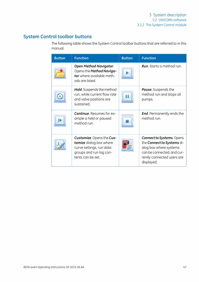
System Control toolbar buttonsThe following table shows the System Control toolbar buttons that are referred to in thismanual.
FunctionButtonFunctionButton
Run. Starts a method run.Open Method Navigator.Opens theMethodNaviga-tor where available meth-ods are listed.
Pause. Suspends themethod run and stops allpumps.
Hold. Suspends the methodrun, while current flow rateand valve positions aresustained.
End. Permanently ends themethod run.
Continue. Resumes for ex-ample a held or pausedmethod run.
Connect to Systems. OpenstheConnect to Systemsdi-alog box where systemscan be connected, and cur-rently connected users aredisplayed.
Customize. Opens theCus-tomize dialog box wherecurve settings, run datagroups and run log con-tents can be set.
ÄKTA avant Operating Instructions 29-1015-56 AA 47
3 System description3.2 UNICORN software
3.2.2 The System Control module
4 Installation
About this sectionThis section provides the instructions necessary to enable users and service personnelto: install the instrument, install the computer, and install the software.
Read the entire Installation chapter before starting to install the ÄKTA avant instrument.
For information on how to how to unpack the ÄKTA avant instrument and howto lift the instrument onto a laboratory bench see ÄKTA avant Unpacking In-structions.
Note:
In this sectionThis sections contains the following subsections:
See pageSection
494.1 Site preparation
644.2 Hardware installation
784.3 Software installation
794.4 Start UNICORN and connect to system
824.5 Prime inlets and purge pump heads
1004.6 Performance tests
48 ÄKTA avant Operating Instructions 29-1015-56 AA
4 Installation
4.1 Site preparation
IntroductionThis subsection describes the site planning and the preparations necessary to performbefore installation of an ÄKTA avant system. The purpose is to provide planners andtechnical staff with the data needed to prepare the laboratory for the installation.
The laboratory site must be planned and prepared before installing the ÄKTA avantsystem. The performance specifications of the system can be met only if the laboratoryenvironment fulfills the requirements stated in this chapter. The time spent in preparingthe laboratory will contribute to the long term performance of the systems.
In this subsection
See pageSection
504.1.1 Delivery and storage
524.1.2 Room requirements
564.1.3 Site environment
574.1.4 Power requirements
594.1.5 Computer requirements
614.1.6 Required materials
ÄKTA avant Operating Instructions 29-1015-56 AA 49
4 Installation4.1 Site preparation
4.1.1 Delivery and storage
IntroductionThis section describes the requirements for receiving the delivery box and storing theinstrument before installation.
WARNINGHeavy object. The ÄKTA avant instrument weighs about 116 kg.Use proper lifting equipment, or use four or more persons whenmoving the instrument. All lifting and moving must be performedin accordance with local regulations.
When you receive the delivery• Record on the receiving documents if there is any apparent damage on the delivery
box. Inform your GE representative of such damage.
• Move the delivery box to a protected location indoors.
Delivery boxÄKTA avant instruments are shipped in a delivery box with the following dimensions andweight:
WeightDimensions (mm)Contents
155 kg1000 × 900 × 800(width × height × depth)
ÄKTA avant instrument with ac-cessories
Storage requirementsThe delivery boxes should be stored at a protected place indoors. The following storagerequirements must be fulfilled for the unopened boxes:
Allowed rangeParameter
-25°C to 60°CAmbient temperature, storage
20% to 95%, noncondensingRelative humidity
50 ÄKTA avant Operating Instructions 29-1015-56 AA
4 Installation4.1 Site preparation4.1.1 Delivery and storage
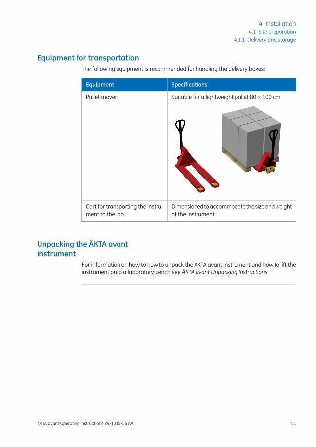
Equipment for transportationThe following equipment is recommended for handling the delivery boxes:
SpecificationsEquipment
Suitable for a lightweight pallet 80 × 100 cmPallet mover
Dimensioned to accommodate the size and weightof the instrument
Cart for transporting the instru-ment to the lab
Unpacking the ÄKTA avantinstrument
For information on how to how to unpack the ÄKTA avant instrument and how to lift theinstrument onto a laboratory bench see ÄKTA avant Unpacking Instructions.
ÄKTA avant Operating Instructions 29-1015-56 AA 51
4 Installation4.1 Site preparation
4.1.1 Delivery and storage
4.1.2 Room requirements
IntroductionThis section describes the requirements for the transportation route and the room wherethe ÄKTA avant instrument is placed.
WARNING
• Protective ground. The product must always be connectedto a grounded power outlet.
• Power cord. Only use power cords with approved plugs deliv-ered or approved by GE.
• Access to power switch and power cord with plug. Do notblock access to the power switch and power cord. The powerswitch must always be easy to access. The power cord withplug must always be easy to disconnect.
• Explosion hazard. To avoid building up an explosive atmo-sphere when using flammable liquids, make sure that the roomventilation meets the local requirements.
Transportation routeDoors, corridors and elevators must have a minimum width of 75 cm to allow for trans-porting the instrument. Allow additional space for moving around corners.
52 ÄKTA avant Operating Instructions 29-1015-56 AA
4 Installation4.1 Site preparation4.1.2 Room requirements
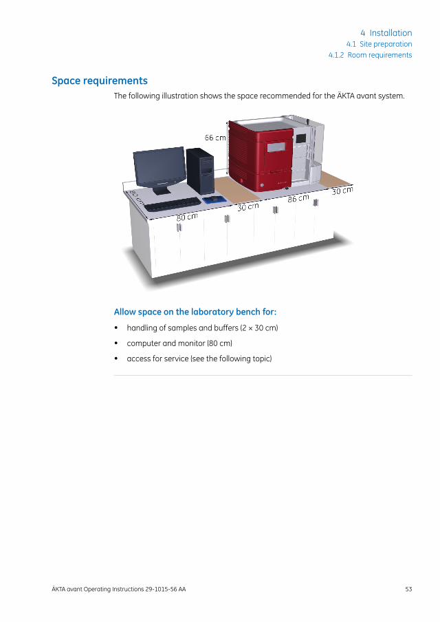
Space requirementsThe following illustration shows the space recommended for the ÄKTA avant system.
Allow space on the laboratory bench for:
• handling of samples and buffers (2 × 30 cm)
• computer and monitor (80 cm)
• access for service (see the following topic)
ÄKTA avant Operating Instructions 29-1015-56 AA 53
4 Installation4.1 Site preparation
4.1.2 Room requirements
Service accessTo access the rear panel, the instrument can be rotated on a swivel foot. There must beat least 20 cm additional space on the bench to allow for free rotation.
WARNINGRotating the instrument. Make sure that there is always at least20 cm of free space around the ÄKTA avant instrument to allowfor sufficient ventilation and rotation on the swivel foot. When ro-tating the instrument, take care not to stretch or squeeze tubingor cables. A disconnected cable may cause power interruption ornetwork interruption. Stretched tubing may cause bottles to fall,resulting in liquid spillage and shattered glass. Squeezed tubingmay cause increase in pressure, or block liquid flow. To avoid therisk of knocking over bottles, always place bottles on the buffertray, and close the doors before rotating the instrument.
Laboratory benchThe bench must be clean, flat and stable to support the weight of the ÄKTA avant system,see the following table Equipment weight.
54 ÄKTA avant Operating Instructions 29-1015-56 AA
4 Installation4.1 Site preparation4.1.2 Room requirements
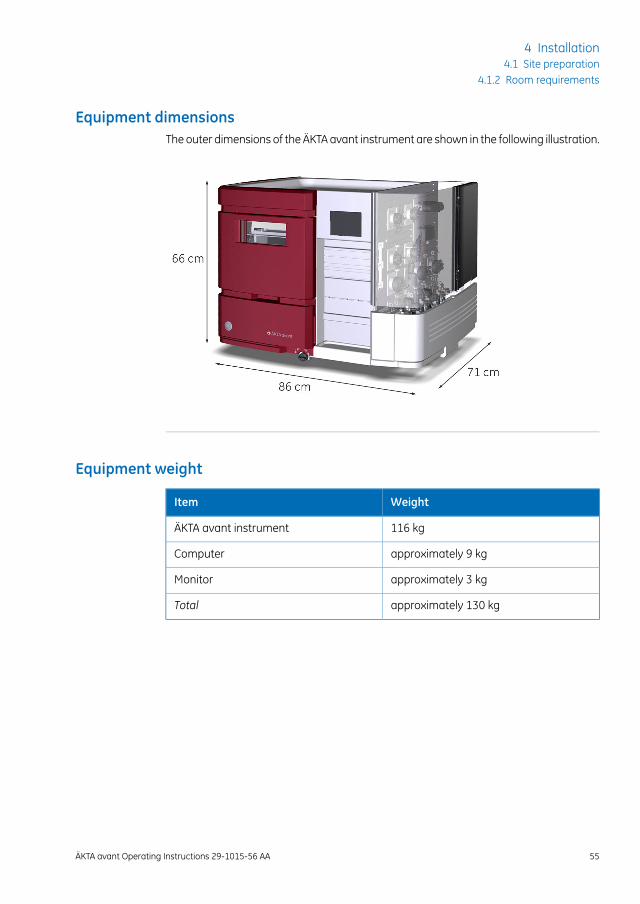
Equipment dimensionsThe outer dimensions of the ÄKTA avant instrument are shown in the following illustration.
Equipment weight
WeightItem
116 kgÄKTA avant instrument
approximately 9 kgComputer
approximately 3 kgMonitor
approximately 130 kgTotal
ÄKTA avant Operating Instructions 29-1015-56 AA 55
4 Installation4.1 Site preparation
4.1.2 Room requirements
4.1.3 Site environment
IntroductionThis section describes the environmental requirements for installation of the the ÄKTAavant instrument.
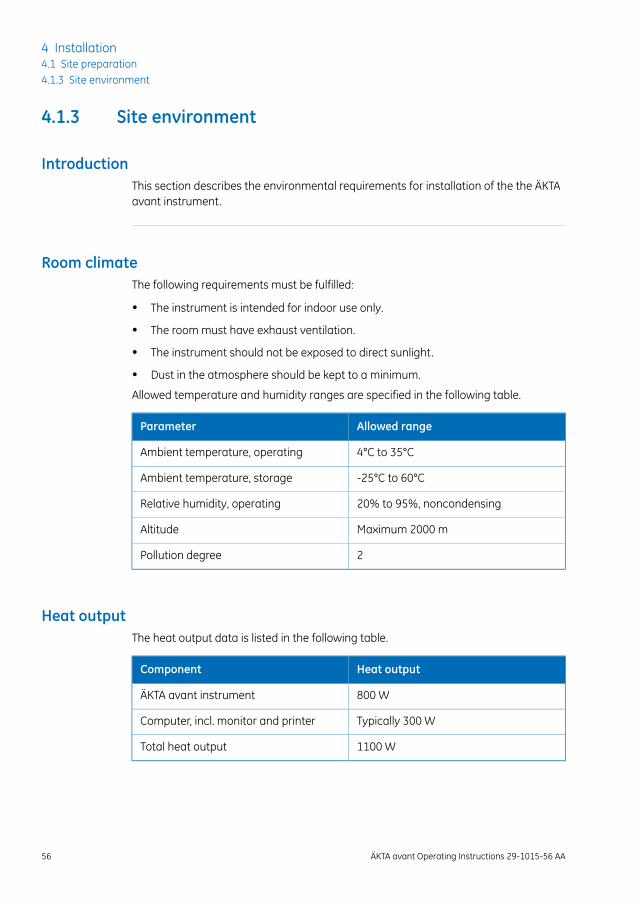
Room climateThe following requirements must be fulfilled:
• The instrument is intended for indoor use only.
• The room must have exhaust ventilation.
• The instrument should not be exposed to direct sunlight.
• Dust in the atmosphere should be kept to a minimum.
Allowed temperature and humidity ranges are specified in the following table.
Allowed rangeParameter
4°C to 35°CAmbient temperature, operating
-25°C to 60°CAmbient temperature, storage
20% to 95%, noncondensingRelative humidity, operating
Maximum 2000 mAltitude
2Pollution degree
Heat outputThe heat output data is listed in the following table.
Heat outputComponent
800 WÄKTA avant instrument
Typically 300 WComputer, incl. monitor and printer
1100 WTotal heat output
56 ÄKTA avant Operating Instructions 29-1015-56 AA
4 Installation4.1 Site preparation4.1.3 Site environment
4.1.4 Power requirements
IntroductionThis section describes the power supply requirements for the ÄKTA avant instrument.
WARNING
• Protective ground. The product must always be connectedto a grounded power outlet.
• Power cord. Only use power cords with approved plugs deliv-ered or approved by GE.
• Access to power switch and power cord with plug. Do notblock access to the power switch and power cord. The powerswitch must always be easy to access. The power cord withplug must always be easy to disconnect.
• Supply voltage.Before connecting the power cord, make surethat the supply voltage at the wall outlet corresponds to themarking on the instrument.
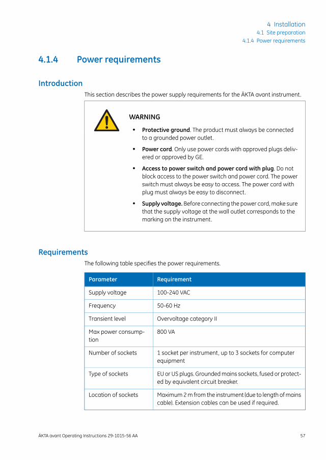
RequirementsThe following table specifies the power requirements.
RequirementParameter
100-240 VACSupply voltage
50-60 HzFrequency
Overvoltage category IITransient level
800 VAMax power consump-tion
1 socket per instrument, up to 3 sockets for computerequipment
Number of sockets
EU or US plugs. Grounded mains sockets, fused or protect-ed by equivalent circuit breaker.
Type of sockets
Maximum 2 m from the instrument (due to length of mainscable). Extension cables can be used if required.
Location of sockets
ÄKTA avant Operating Instructions 29-1015-56 AA 57
4 Installation4.1 Site preparation
4.1.4 Power requirements
Quality of powerThe mains power supply must be stable and conform to specifications at all times toensure reliable operation of the ÄKTA avant instrument. There should be no transient orslow changes in average voltage outside the limits specified above.
58 ÄKTA avant Operating Instructions 29-1015-56 AA
4 Installation4.1 Site preparation4.1.4 Power requirements

4.1.5 Computer requirements
IntroductionÄKTA avant systems are controlled by UNICORN software running on a PC. The PC canbe part of the delivery or be supplied locally.
The PC used must fulfill the recommendations stated in this section.
General computer specificationsThe table below describes the recommended computer specifications for a UNICORNsystem operating with ÄKTA instruments. Installation is supported for Windows 7 Profes-sional, 32-bit or 64-bit, with Service Pack 1.
E-License ServerWorkstationinstallation
Database ServerUNICORN Client
500 MB12 GB6 GB6 GBMin. free diskspace
2 GB3 GB3 GB3 GBMin. availableRAM
NTFSNTFSNTFSNTFSDisc format
Windows 7Professional SP132/64 bit
Windows 7Professional SP132/64 bit
Windows 7Professional SP132/64 bit
Windows 7Professional SP132/64 bit
OS
Windows Server2008/R2 64 bit
Windows Server2008/R2 64 bit
English (U.S.) Code1033
English (U.S.) Code1033
English (U.S.) Code1033
English (U.S.)Code 1033
OS language
Intel Dual Core (orfaster)
Intel Dual Core (orfaster)
Intel Dual Core (orfaster)
Intel Dual Core (orfaster)
Architecture
Note: • UNICORN is tested using an English operating system version. Using otherlanguage versions of the operating system may cause errors.
• A screen resolution of 1280x1024 or higher is recommended. Parts of theUNICORN user interface may not be displayed properly using a lower res-olution.
• Changing the default font and font size in Windows may cause problemsin the UNICORN user interface.
ÄKTA avant Operating Instructions 29-1015-56 AA 59
4 Installation4.1 Site preparation
4.1.5 Computer requirements
• The Windows basic color scheme is recommended1 .
• Using the Windows 7 Aero color scheme is not recommended.
• Windows power save features should be turned off to avoid conflicts withsystem operations.
• UNICORN is not compatible with the Windows 7 feature High DPI Aware-ness, which allows the graphic user interface to be scaled. The interfacescale must remain at 100% to avoid issues with clipping and misaligningof parts of the UNICORN user interface. Normally, the scale is set at 100%by default.
1 UNICORN must be closed when the color scheme is changed.
60 ÄKTA avant Operating Instructions 29-1015-56 AA
4 Installation4.1 Site preparation4.1.5 Computer requirements
4.1.6 Required materials
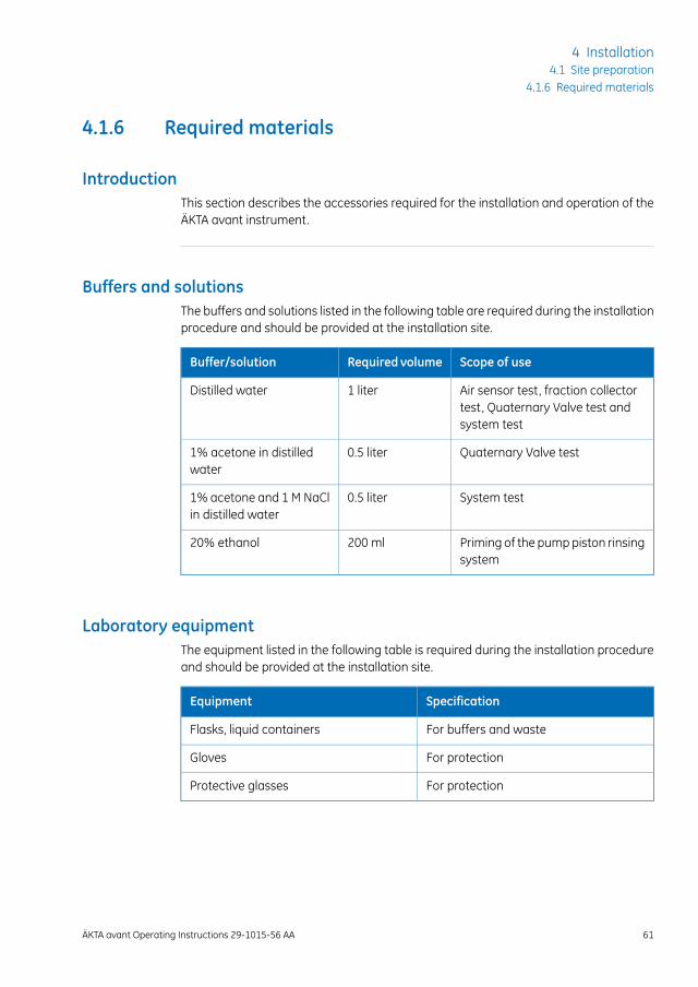
IntroductionThis section describes the accessories required for the installation and operation of theÄKTA avant instrument.
Buffers and solutionsThe buffers and solutions listed in the following table are required during the installationprocedure and should be provided at the installation site.
Scope of useRequired volumeBuffer/solution
Air sensor test, fraction collectortest, Quaternary Valve test andsystem test
1 literDistilled water
Quaternary Valve test0.5 liter1% acetone in distilledwater
System test0.5 liter1% acetone and 1 M NaClin distilled water
Priming of the pump piston rinsingsystem
200 ml20% ethanol
Laboratory equipmentThe equipment listed in the following table is required during the installation procedureand should be provided at the installation site.
SpecificationEquipment
For buffers and wasteFlasks, liquid containers
For protectionGloves
For protectionProtective glasses
ÄKTA avant Operating Instructions 29-1015-56 AA 61
4 Installation4.1 Site preparation
4.1.6 Required materials
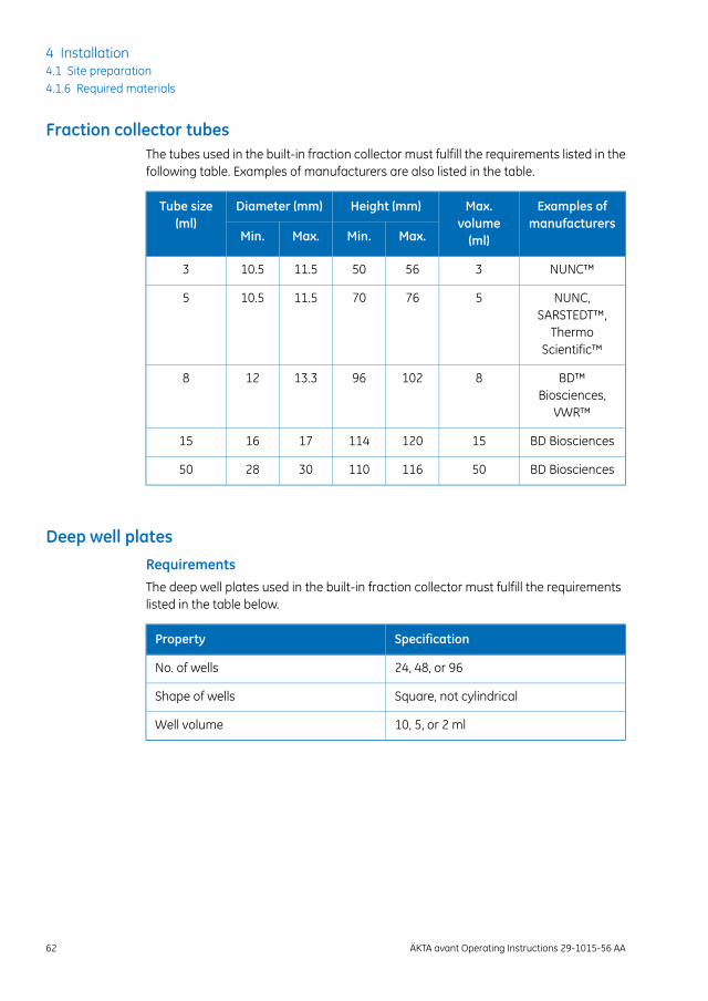
Fraction collector tubesThe tubes used in the built-in fraction collector must fulfill the requirements listed in thefollowing table. Examples of manufacturers are also listed in the table.
Examples ofmanufacturers
Max.volume(ml)
Height (mm)Diameter (mm)Tube size(ml)
Max.Min.Max.Min.
NUNC™3565011.510.53
NUNC,SARSTEDT™,
ThermoScientific™
5767011.510.55
BD™Biosciences,
VWR™
81029613.3128
BD Biosciences15120114171615
BD Biosciences50116110302850
Deep well platesRequirementsThe deep well plates used in the built-in fraction collector must fulfill the requirementslisted in the table below.
SpecificationProperty
24, 48, or 96No. of wells
Square, not cylindricalShape of wells
10, 5, or 2 mlWell volume
62 ÄKTA avant Operating Instructions 29-1015-56 AA
4 Installation4.1 Site preparation4.1.6 Required materials
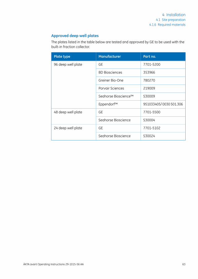
Approved deep well platesThe plates listed in the table below are tested and approved by GE to be used with thebuilt-in fraction collector.
Part no.ManufacturerPlate type
7701-5200GE96 deep well plate
353966BD Biosciences
780270Greiner Bio-One
219009Porvair Sciences
S30009Seahorse Bioscience™
951033405/ 0030 501.306Eppendorf™
7701-5500GE48 deep well plate
S30004Seahorse Bioscience
7701-5102GE24 deep well plate
S30024Seahorse Bioscience
ÄKTA avant Operating Instructions 29-1015-56 AA 63
4 Installation4.1 Site preparation
4.1.6 Required materials
4.2 Hardware installation
About this chapterThis section describes the installation procedure of an ÄKTA avant system.
For information on how to how to unpack the ÄKTA avant instrument and howto lift the instrument onto a laboratory bench see ÄKTA avant Unpacking In-structions.
Note:
WARNING
• Protective ground. The product must always be connectedto a grounded power outlet.
• Power cord. Only use power cords with approved plugs deliv-ered or approved by GE.
• Access to power switch and power cord with plug. Do notblock access to the power switch and power cord. The powerswitch must always be easy to access. The power cord withplug must always be easy to disconnect.
In this sectionThis section contains the following subsections:
See pageSection
654.2.1 Install the computer equipment
664.2.2 Connect the system units
704.2.3 Prepare waste tubing
734.2.4 Install the Barcode Scanner 2-D and the pH electrode
744.2.5 Prepare the pump rinsing system
774.2.6 Start the instrument and the computer
64 ÄKTA avant Operating Instructions 29-1015-56 AA
4 Installation4.2 Hardware installation

4.2.1 Install the computer equipment
IntroductionThe computer is supplied as a part of the ÄKTA avant delivery, or supplied locally.
Unpacking and installingUnpack and install the computer according to the manufacturer's instructions.
NOTICEAny computer used with the equipment must comply with IEC60950 and be installed and used according to the manufacturer'sinstructions.
ÄKTA avant Operating Instructions 29-1015-56 AA 65
4 Installation4.2 Hardware installation
4.2.1 Install the computer equipment
4.2.2 Connect the system units
IntroductionThe following interconnections must be made:
• power supply to the ÄKTA avant instrument
• power supply to the computer equipment
• network connection between the computer and the ÄKTA avant instrument
WARNING
• Power cord. Only use power cords with approved plugs deliv-ered or approved by GE.
• Supply voltage.Before connecting the power cord, make surethat the supply voltage at the wall outlet corresponds to themarking on the instrument.
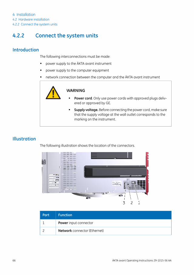
IllustrationThe following illustration shows the location of the connectors.
FunctionPart
Power input connector1
Network connector (Ethernet)2
66 ÄKTA avant Operating Instructions 29-1015-56 AA
4 Installation4.2 Hardware installation4.2.2 Connect the system units
FunctionPart
UniNet-9 connectors
Note:
Termination plugsmust be connected to the connectors that are not in use.
3
Other connectors are for use by authorized service engineers only.
NOTICEMisuse of UniNet-9 connectors. The UniNet-9 connectors at therear panel should not be mistaken for Firewire connectors. Do notconnect any external equipment to the UniNet-9 connectors. Donot disconnect or move the UniNet-9 bus cable.
ÄKTA avant Operating Instructions 29-1015-56 AA 67
4 Installation4.2 Hardware installation
4.2.2 Connect the system units
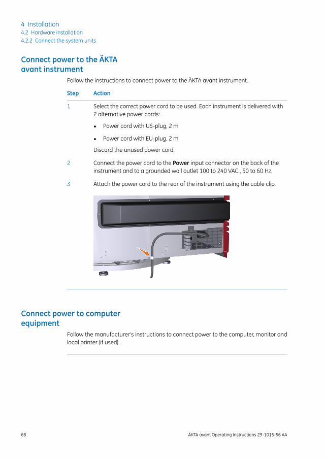
Connect power to the ÄKTAavant instrument
Follow the instructions to connect power to the ÄKTA avant instrument.
ActionStep
Select the correct power cord to be used. Each instrument is delivered with2 alternative power cords:
1
• Power cord with US-plug, 2 m
• Power cord with EU-plug, 2 m
Discard the unused power cord.
Connect the power cord to the Power input connector on the back of theinstrument and to a grounded wall outlet 100 to 240 VAC , 50 to 60 Hz.
2
Attach the power cord to the rear of the instrument using the cable clip.3
Connect power to computerequipment
Follow the manufacturer's instructions to connect power to the computer, monitor andlocal printer (if used).
68 ÄKTA avant Operating Instructions 29-1015-56 AA
4 Installation4.2 Hardware installation4.2.2 Connect the system units
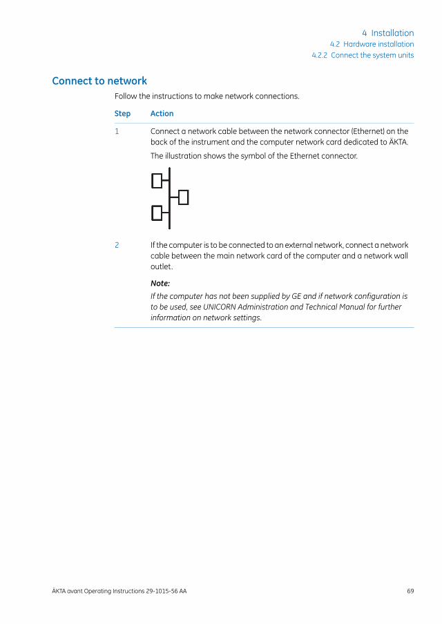
Connect to networkFollow the instructions to make network connections.
ActionStep
Connect a network cable between the network connector (Ethernet) on theback of the instrument and the computer network card dedicated to ÄKTA.
The illustration shows the symbol of the Ethernet connector.
1
If the computer is to be connected to an external network, connect a networkcable between the main network card of the computer and a network walloutlet.
Note:
If the computer has not been supplied by GE and if network configuration isto be used, see UNICORN Administration and Technical Manual for furtherinformation on network settings.
2
ÄKTA avant Operating Instructions 29-1015-56 AA 69
4 Installation4.2 Hardware installation
4.2.2 Connect the system units
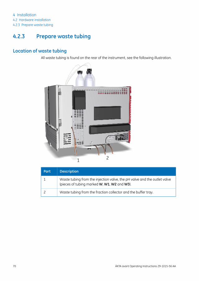
4.2.3 Prepare waste tubing
Location of waste tubingAll waste tubing is found on the rear of the instrument, see the following illustration.
1 2
DescriptionPart
Waste tubing from the injection valve, the pH valve and the outlet valve(pieces of tubing marked W, W1, W2 and W3).
1
Waste tubing from the fraction collector and the buffer tray.2
70 ÄKTA avant Operating Instructions 29-1015-56 AA
4 Installation4.2 Hardware installation4.2.3 Prepare waste tubing
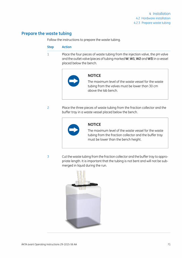
Prepare the waste tubingFollow the instructions to prepare the waste tubing.
ActionStep
Place the four pieces of waste tubing from the injection valve, the pH valveand the outlet valve (pieces of tubing markedW,W1,W2 andW3) in a vesselplaced below the bench.
1
NOTICEThe maximum level of the waste vessel for the wastetubing from the valves must be lower than 30 cmabove the lab bench.
Place the three pieces of waste tubing from the fraction collector and thebuffer tray in a waste vessel placed below the bench.
2
NOTICEThe maximum level of the waste vessel for the wastetubing from the fraction collector and the buffer traymust be lower than the bench height.
Cut the waste tubing from the fraction collector and the buffer tray to appro-priate length. It is important that the tubing is not bent and will not be sub-merged in liquid during the run.
3
ÄKTA avant Operating Instructions 29-1015-56 AA 71
4 Installation4.2 Hardware installation
4.2.3 Prepare waste tubing

If the tubing is too short, replace it with new tubing. Do not lengthen the tubingas this might cause obstruction of the tubing and flooding in the fraction col-lector chamber.
Note:
CAUTIONMake sure that the waste vessels will hold all the produced volumeof the run. For ÄKTA avant 25, a suitable waste vessel should typi-cally have a volume of 2 to 10 liters. For ÄKTA avant 150, a wastevessel should have a volume of 40 liters.
72 ÄKTA avant Operating Instructions 29-1015-56 AA
4 Installation4.2 Hardware installation4.2.3 Prepare waste tubing
4.2.4 Install the Barcode Scanner 2-D and the pH electrode
IntroductionThis section describes how to install the Barcode Scanner 2-D and the pH electrode.
Install the barcode scannerConnect the cable of the Barcode Scanner 2-D to the scanner head and to a USB porton the computer.
Install the pH electrodeIf pH monitoring is to be used, you need to replace the dummy electrode mounted atdelivery with a pH electrode.
CAUTIONpHelectrode. Handle the pH electrode with care. The glass tip maybreak and cause injury.
Follow the instructions to install the pH electrode.
ActionStep
Unpack the pH electrode. Make sure that the electrode is not broken or dry.1
Unscrew the dummy electrode from the flow cell.2
Pull off the plug from the connector on the front of the pH valve, and storethe plug together with the dummy electrode.
3
Remove the cover from the tip of the pH electrode.4
Carefully insert the electrode in the flow cell. Tighten the locking ring by handto secure the electrode.
5
Connect the pH electrode cable to the connector on front of the pH valve.6
ÄKTA avant Operating Instructions 29-1015-56 AA 73
4 Installation4.2 Hardware installation
4.2.4 Install the Barcode Scanner 2-D and the pH electrode
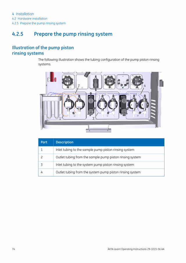
4.2.5 Prepare the pump rinsing system
Illustration of the pump pistonrinsing systems
The following illustration shows the tubing configuration of the pump piston rinsingsystems.
2 4
31
DescriptionPart
Inlet tubing to the sample pump piston rinsing system1
Outlet tubing from the sample pump piston rinsing system2
Inlet tubing to the system pump piston rinsing system3
Outlet tubing from the system pump piston rinsing system4
74 ÄKTA avant Operating Instructions 29-1015-56 AA
4 Installation4.2 Hardware installation4.2.5 Prepare the pump rinsing system
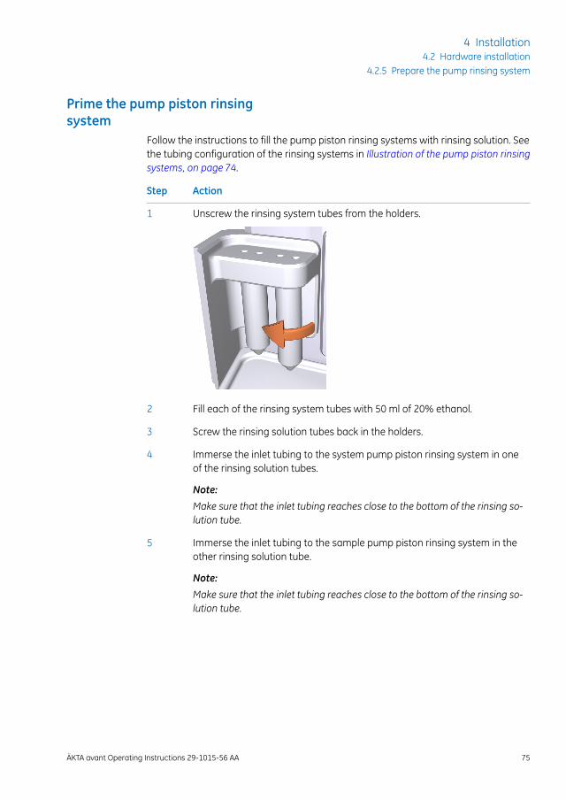
Prime the pump piston rinsingsystem
Follow the instructions to fill the pump piston rinsing systems with rinsing solution. Seethe tubing configuration of the rinsing systems in Illustration of the pump piston rinsingsystems, on page 74.
ActionStep
Unscrew the rinsing system tubes from the holders.1
Fill each of the rinsing system tubes with 50 ml of 20% ethanol.2
Screw the rinsing solution tubes back in the holders.3
Immerse the inlet tubing to the system pump piston rinsing system in oneof the rinsing solution tubes.
Note:
Make sure that the inlet tubing reaches close to the bottom of the rinsing so-lution tube.
4
Immerse the inlet tubing to the sample pump piston rinsing system in theother rinsing solution tube.
Note:
Make sure that the inlet tubing reaches close to the bottom of the rinsing so-lution tube.
5
ÄKTA avant Operating Instructions 29-1015-56 AA 75
4 Installation4.2 Hardware installation
4.2.5 Prepare the pump rinsing system
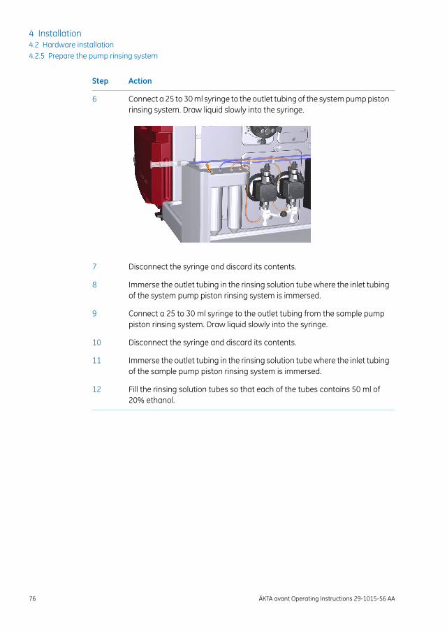
ActionStep
Connect a 25 to 30 ml syringe to the outlet tubing of the system pump pistonrinsing system. Draw liquid slowly into the syringe.
6
Disconnect the syringe and discard its contents.7
Immerse the outlet tubing in the rinsing solution tube where the inlet tubingof the system pump piston rinsing system is immersed.
8
Connect a 25 to 30 ml syringe to the outlet tubing from the sample pumppiston rinsing system. Draw liquid slowly into the syringe.
9
Disconnect the syringe and discard its contents.10
Immerse the outlet tubing in the rinsing solution tube where the inlet tubingof the sample pump piston rinsing system is immersed.
11
Fill the rinsing solution tubes so that each of the tubes contains 50 ml of20% ethanol.
12
76 ÄKTA avant Operating Instructions 29-1015-56 AA
4 Installation4.2 Hardware installation4.2.5 Prepare the pump rinsing system
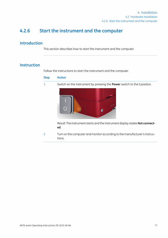
4.2.6 Start the instrument and the computer
IntroductionThis section describes how to start the instrument and the computer.
InstructionFollow the instructions to start the instrument and the computer.
ActionStep
Switch on the instrument by pressing the Power switch to the I position.1
Result: The instrument starts and the Instrument display statesNot connect-ed.
Turn on the computer and monitor according to the manufacturer's instruc-tions.
2
ÄKTA avant Operating Instructions 29-1015-56 AA 77
4 Installation4.2 Hardware installation
4.2.6 Start the instrument and the computer
4.3 Software installation
IntroductionThis section gives an overview of the different UNICORN installation types.
Detailed information about software installation and configuration is available in theUNICORN Administration and Technical Manual.
Software installationsYou can install UNICORN in one of the following configurations:
• as a complete UNICORN installation on a stand-alone workstation (full installation)
• as a UNICORN database and license server (custom installation)
• as a UNICORN software client and instrument server software on a network clientstation (custom installation)
You can also do the following when installing UNICORN:
• define a system as part of the installation
• configure E-licenses
• configure Windows settings necessary for the UNICORN Process Picture in a networkdeployment
• configure firewall settings, when necessary
• upgrade UNICORN
• remove UNICORN installations
• set up a system printer
78 ÄKTA avant Operating Instructions 29-1015-56 AA
4 Installation4.3 Software installation
4.4 Start UNICORN and connect to system
IntroductionThis section describes how to start and log on to UNICORN and how to connect the in-strument to UNICORN.
Start UNICORN and log onFollow the instructions to start UNICORN and log on to the program. A valid e-licensemust be available for the workstation. SeeUNICORNAdministration and TechnicalManualfor more information about e-licenses.
ActionStep
Double-click the UNICORN icon on the desktop.1
Result: The Log On dialog box opens.
Note:
If there is no connection to the database it is still possible to log on to UNICORNand control a running system. The Log On dialog box will give the option tostart System Control without a database. Click Start System Control toproceed to the next Log On dialog box.
ÄKTA avant Operating Instructions 29-1015-56 AA 79
4 Installation4.4 Start UNICORN and connect to system
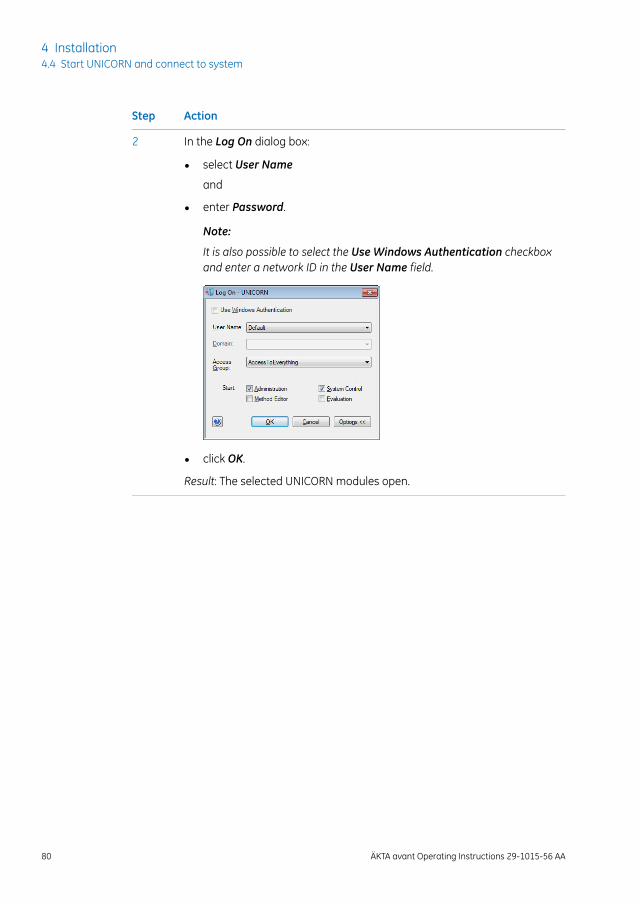
ActionStep
In the Log On dialog box:2
• select User Name
and
• enter Password.
Note:
It is also possible to select the Use Windows Authentication checkboxand enter a network ID in the User Name field.
• click OK.
Result: The selected UNICORN modules open.
80 ÄKTA avant Operating Instructions 29-1015-56 AA
4 Installation4.4 Start UNICORN and connect to system
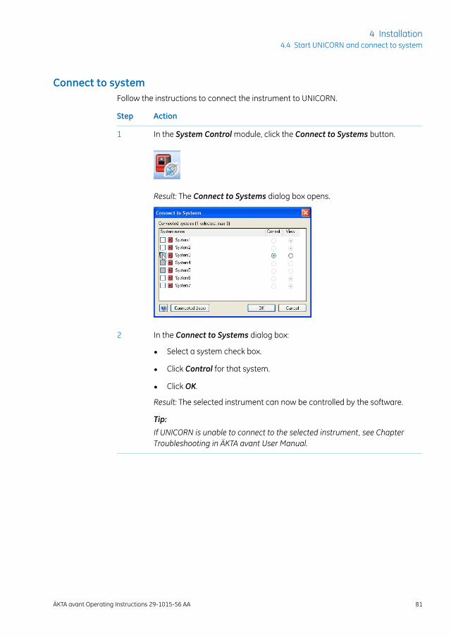
Connect to systemFollow the instructions to connect the instrument to UNICORN.
ActionStep
In the System Control module, click the Connect to Systems button.1
Result: The Connect to Systems dialog box opens.
In the Connect to Systems dialog box:2
• Select a system check box.
• Click Control for that system.
• Click OK.
Result: The selected instrument can now be controlled by the software.
Tip:
If UNICORN is unable to connect to the selected instrument, see ChapterTroubleshooting in ÄKTA avant User Manual.
ÄKTA avant Operating Instructions 29-1015-56 AA 81
4 Installation4.4 Start UNICORN and connect to system
4.5 Prime inlets and purge pump heads
About this sectionBefore using the sample pump or system pumps it is important to do the following:
• Prime the inlets (fill the inlets with liquid).
• Purge the pumps (remove air from the pump heads).
This section describes how to prime the buffer inlets, sample inlets, and Q inlets, andhow to purge the system pumps and the sample pump.
In this sectionThis section contains the following subsections:
See pageSection
834.5.1 Prime buffer inlets and purge system pumps
904.5.2 Prime sample inlets and purge Sample Pump
954.5.3 Prime Q inlets
82 ÄKTA avant Operating Instructions 29-1015-56 AA
4 Installation4.5 Prime inlets and purge pump heads
4.5.1 Prime buffer inlets and purge system pumps
OverviewThe procedure consists of the following stages:
DescriptionStage
Prime all inlet tubing to be used during the run.1
Validate priming of inlet tubing.2
Purge System Pump B if pressure signal indicates air bubbles.3
Validate purge of System Pump B.4
Purge System Pump A if pressure signal indicates air bubbles.5
Validate purge of System Pump A.6
End the run.7
To increase life length of the pump sealing rings, make sure that the pumprinsing system is filled with fresh rinsing solution.
Note:
The procedures for purging the pump heads and priming the inlets using theProcess Picture, are described in the following topic. It is also possible toperform the procedures from theManual instructions dialog box.
Tip:
Prime inlet tubingFollow the instructions to fill all A and B inlet tubing to be used in the run with appropriatebuffer/solution.
ActionStep
Make sure that all inlet tubing that is to be used during the method run isplaced in the correct buffer.
1
Open the System Control module.2
ÄKTA avant Operating Instructions 29-1015-56 AA 83
4 Installation4.5 Prime inlets and purge pump heads
4.5.1 Prime buffer inlets and purge system pumps
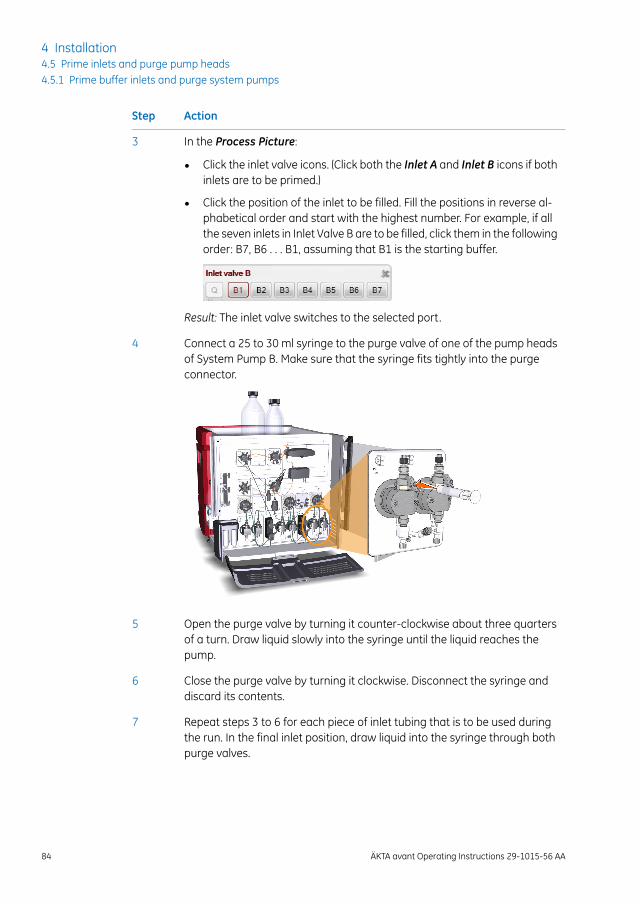
ActionStep
In the Process Picture:3
• Click the inlet valve icons. (Click both the Inlet A and Inlet B icons if bothinlets are to be primed.)
• Click the position of the inlet to be filled. Fill the positions in reverse al-phabetical order and start with the highest number. For example, if allthe seven inlets in Inlet Valve B are to be filled, click them in the followingorder: B7, B6 . . . B1, assuming that B1 is the starting buffer.
Result: The inlet valve switches to the selected port.
Connect a 25 to 30 ml syringe to the purge valve of one of the pump headsof System Pump B. Make sure that the syringe fits tightly into the purgeconnector.
4
Open the purge valve by turning it counter-clockwise about three quartersof a turn. Draw liquid slowly into the syringe until the liquid reaches thepump.
5
Close the purge valve by turning it clockwise. Disconnect the syringe anddiscard its contents.
6
Repeat steps 3 to 6 for each piece of inlet tubing that is to be used duringthe run. In the final inlet position, draw liquid into the syringe through bothpurge valves.
7
84 ÄKTA avant Operating Instructions 29-1015-56 AA
4 Installation4.5 Prime inlets and purge pump heads4.5.1 Prime buffer inlets and purge system pumps
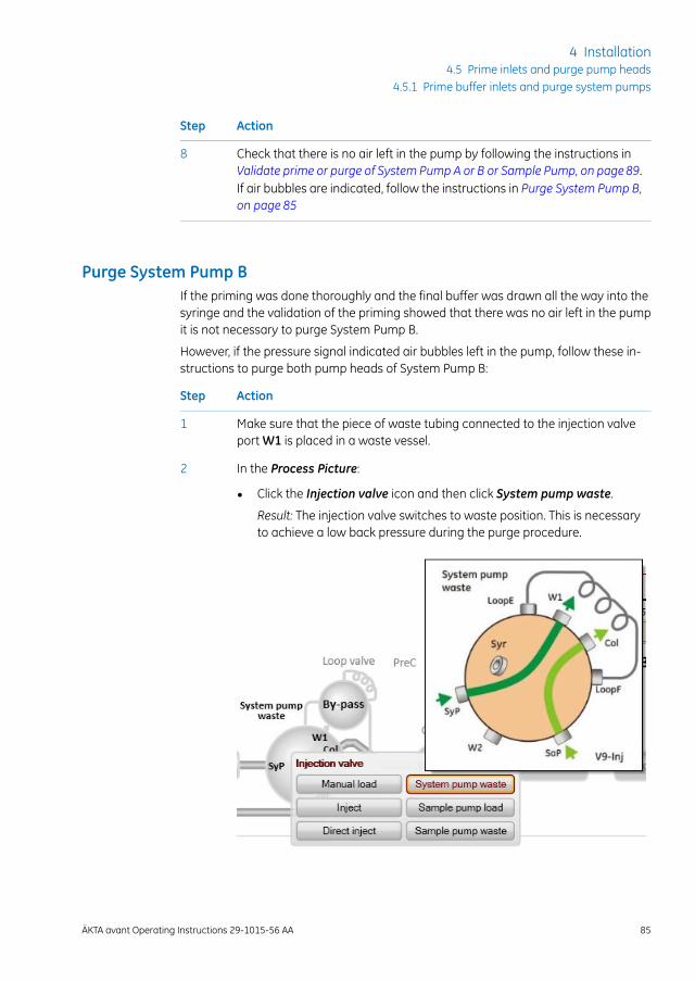
ActionStep
Check that there is no air left in the pump by following the instructions inValidate prime or purge of System Pump A or B or Sample Pump, on page89.If air bubbles are indicated, follow the instructions in Purge System Pump B,on page 85
8
Purge System Pump BIf the priming was done thoroughly and the final buffer was drawn all the way into thesyringe and the validation of the priming showed that there was no air left in the pumpit is not necessary to purge System Pump B.
However, if the pressure signal indicated air bubbles left in the pump, follow these in-structions to purge both pump heads of System Pump B:
ActionStep
Make sure that the piece of waste tubing connected to the injection valveport W1 is placed in a waste vessel.
1
In the Process Picture:2
• Click the Injection valve icon and then click System pump waste.
Result: The injection valve switches to waste position. This is necessaryto achieve a low back pressure during the purge procedure.
ÄKTA avant Operating Instructions 29-1015-56 AA 85
4 Installation4.5 Prime inlets and purge pump heads
4.5.1 Prime buffer inlets and purge system pumps
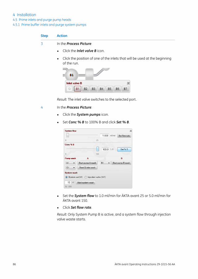
ActionStep
In the Process Picture:3
• Click the Inlet valve B icon.
• Click the position of one of the inlets that will be used at the beginningof the run.
Result: The inlet valve switches to the selected port.
In the Process Picture:4
• Click the System pumps icon.
• Set Conc % B to 100% B and click Set % B.
• Set the System flow to 1.0 ml/min for ÄKTA avant 25 or 5.0 ml/min forÄKTA avant 150.
• Click Set flow rate.
Result: Only System Pump B is active, and a system flow through injectionvalve waste starts.
86 ÄKTA avant Operating Instructions 29-1015-56 AA
4 Installation4.5 Prime inlets and purge pump heads4.5.1 Prime buffer inlets and purge system pumps
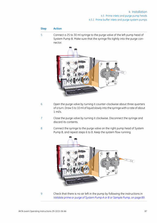
ActionStep
Connect a 25 to 30 ml syringe to the purge valve of the left pump head ofSystem Pump B. Make sure that the syringe fits tightly into the purge con-nector.
5
Open the purge valve by turning it counter-clockwise about three quartersof a turn. Draw 5 to 10 ml of liquid slowly into the syringe with a rate of about1 ml/s.
6
Close the purge valve by turning it clockwise. Disconnect the syringe anddiscard its contents.
7
Connect the syringe to the purge valve on the right pump head of SystemPump B, and repeat steps 6 to 8. Keep the system flow running.
8
Check that there is no air left in the pump by following the instructions inValidate prime or purge of System Pump A or B or Sample Pump, on page89.
9
ÄKTA avant Operating Instructions 29-1015-56 AA 87
4 Installation4.5 Prime inlets and purge pump heads
4.5.1 Prime buffer inlets and purge system pumps
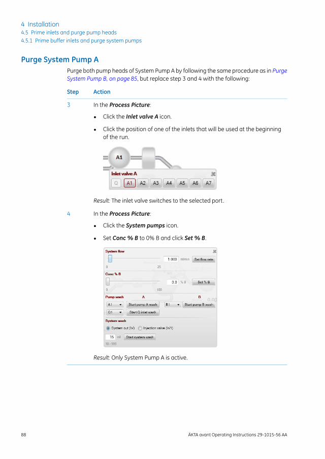
Purge System Pump APurge both pump heads of System Pump A by following the same procedure as in PurgeSystem Pump B, on page 85, but replace step 3 and 4 with the following:
ActionStep
In the Process Picture:3
• Click the Inlet valve A icon.
• Click the position of one of the inlets that will be used at the beginningof the run.
Result: The inlet valve switches to the selected port.
In the Process Picture:4
• Click the System pumps icon.
• Set Conc % B to 0% B and click Set % B.
Result: Only System Pump A is active.
88 ÄKTA avant Operating Instructions 29-1015-56 AA
4 Installation4.5 Prime inlets and purge pump heads4.5.1 Prime buffer inlets and purge system pumps
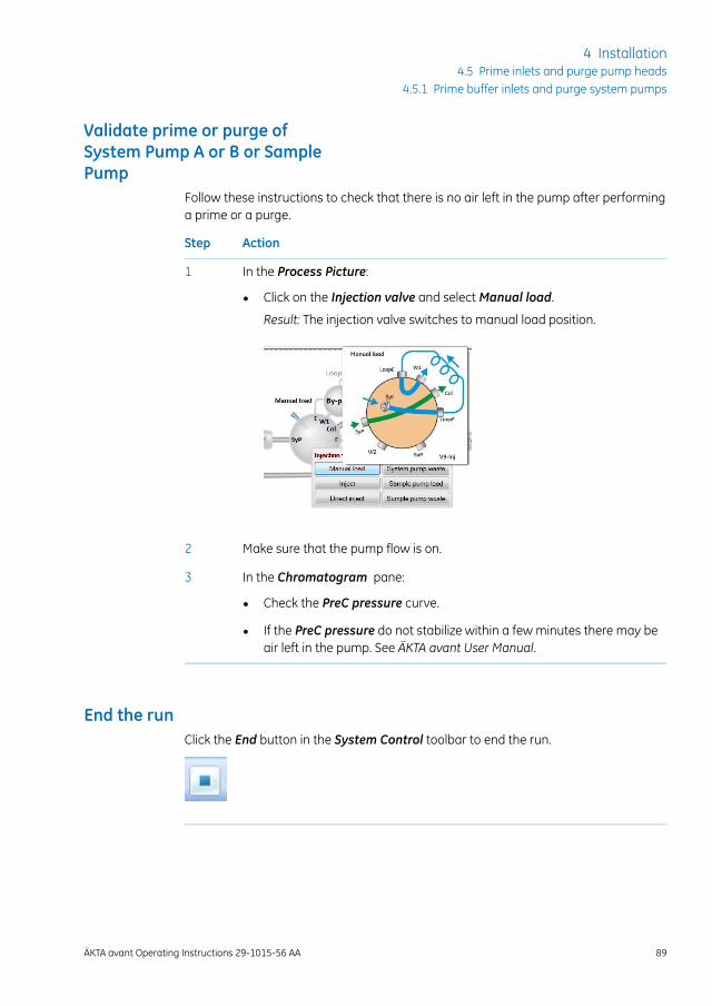
Validate prime or purge ofSystem Pump A or B or SamplePump
Follow these instructions to check that there is no air left in the pump after performinga prime or a purge.
ActionStep
In the Process Picture:1
• Click on the Injection valve and select Manual load.
Result: The injection valve switches to manual load position.
Make sure that the pump flow is on.2
In the Chromatogram pane:3
• Check the PreC pressure curve.
• If the PreC pressure do not stabilize within a few minutes there may beair left in the pump. See ÄKTA avant User Manual.
End the runClick the End button in the System Control toolbar to end the run.
ÄKTA avant Operating Instructions 29-1015-56 AA 89
4 Installation4.5 Prime inlets and purge pump heads
4.5.1 Prime buffer inlets and purge system pumps

4.5.2 Prime sample inlets and purge Sample Pump
OverviewThe procedure consists of the following stages:
DescriptionStage
Prime all sample inlet tubing to be used during the run.1
Validate priming of inlet tubing.2
Purge the sample pump if pressure signal indicates air bubbles.3
Validate purge of the samle pump.4
End the run.5
To increase life length of the pump sealing rings, make sure that the pumprinsing system is filled with fresh rinsing solution.
Note:
Prime sample inletsFollow the instructions below to fill all sample inlet tubing, to be used in the run, withappropriate buffer or sample solution.
ActionStep
Make sure that all sample inlet tubing that is to be used during the methodrun is immersed in the correct samples.
1
Make sure that the waste tubing connected to injection valve port W2 isimmersed in a waste vessel.
2
Open the System Control module.3
90 ÄKTA avant Operating Instructions 29-1015-56 AA
4 Installation4.5 Prime inlets and purge pump heads4.5.2 Prime sample inlets and purge Sample Pump
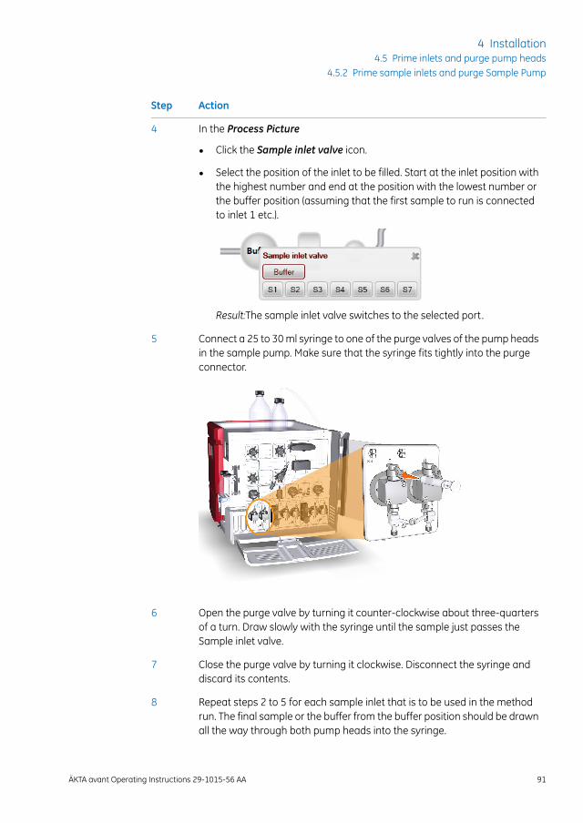
ActionStep
In the Process Picture4
• Click the Sample inlet valve icon.
• Select the position of the inlet to be filled. Start at the inlet position withthe highest number and end at the position with the lowest number orthe buffer position (assuming that the first sample to run is connectedto inlet 1 etc.).
Result:The sample inlet valve switches to the selected port.
Connect a 25 to 30 ml syringe to one of the purge valves of the pump headsin the sample pump. Make sure that the syringe fits tightly into the purgeconnector.
5
Open the purge valve by turning it counter-clockwise about three-quartersof a turn. Draw slowly with the syringe until the sample just passes theSample inlet valve.
6
Close the purge valve by turning it clockwise. Disconnect the syringe anddiscard its contents.
7
Repeat steps 2 to 5 for each sample inlet that is to be used in the methodrun. The final sample or the buffer from the buffer position should be drawnall the way through both pump heads into the syringe.
8
ÄKTA avant Operating Instructions 29-1015-56 AA 91
4 Installation4.5 Prime inlets and purge pump heads
4.5.2 Prime sample inlets and purge Sample Pump
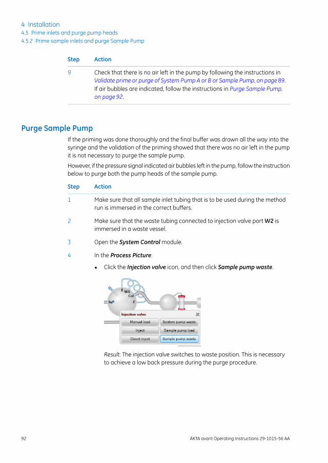
ActionStep
Check that there is no air left in the pump by following the instructions inValidate prime or purge of System Pump A or B or Sample Pump, on page89.If air bubbles are indicated, follow the instructions in Purge Sample Pump,on page 92.
9
Purge Sample PumpIf the priming was done thoroughly and the final buffer was drawn all the way into thesyringe and the validation of the priming showed that there was no air left in the pumpit is not necessary to purge the sample pump.
However, if the pressure signal indicated air bubbles left in the pump, follow the instructionbelow to purge both the pump heads of the sample pump.
ActionStep
Make sure that all sample inlet tubing that is to be used during the methodrun is immersed in the correct buffers.
1
Make sure that the waste tubing connected to injection valve port W2 isimmersed in a waste vessel.
2
Open the System Control module.3
In the Process Picture:4
• Click the Injection valve icon, and then click Sample pump waste.
Result: The injection valve switches to waste position. This is necessaryto achieve a low back pressure during the purge procedure.
92 ÄKTA avant Operating Instructions 29-1015-56 AA
4 Installation4.5 Prime inlets and purge pump heads4.5.2 Prime sample inlets and purge Sample Pump
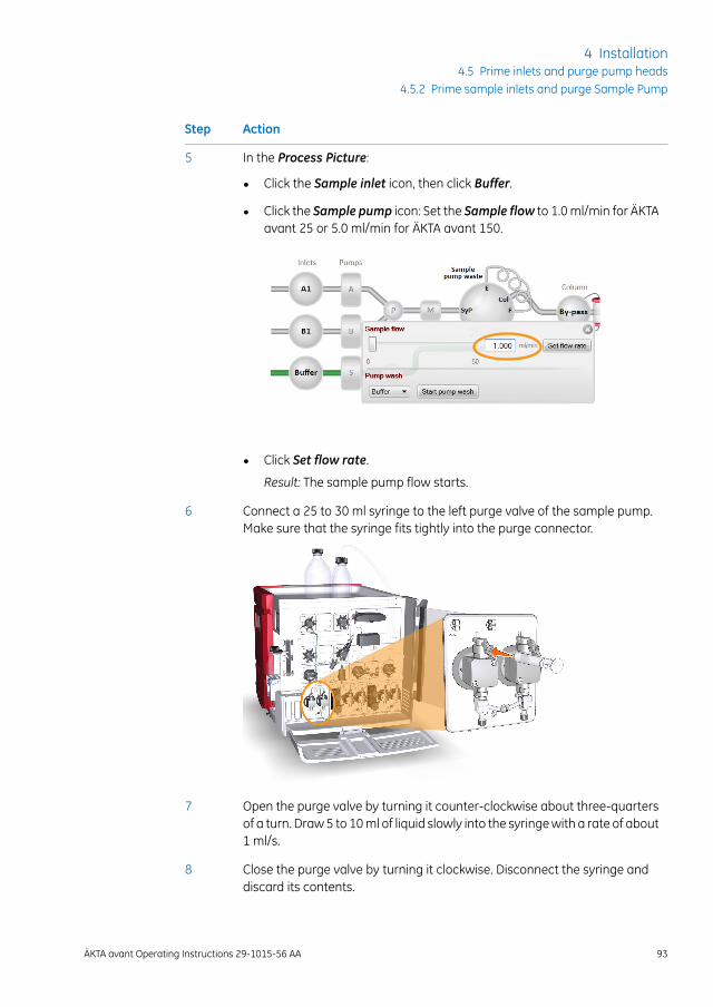
ActionStep
In the Process Picture:5
• Click the Sample inlet icon, then click Buffer.
• Click the Sample pump icon: Set the Sample flow to 1.0 ml/min for ÄKTAavant 25 or 5.0 ml/min for ÄKTA avant 150.
• Click Set flow rate.
Result: The sample pump flow starts.
Connect a 25 to 30 ml syringe to the left purge valve of the sample pump.Make sure that the syringe fits tightly into the purge connector.
6
Open the purge valve by turning it counter-clockwise about three-quartersof a turn. Draw 5 to 10 ml of liquid slowly into the syringe with a rate of about1 ml/s.
7
Close the purge valve by turning it clockwise. Disconnect the syringe anddiscard its contents.
8
ÄKTA avant Operating Instructions 29-1015-56 AA 93
4 Installation4.5 Prime inlets and purge pump heads
4.5.2 Prime sample inlets and purge Sample Pump

ActionStep
Connect the syringe to the right purge valve on the sample pump, and repeatstep 6 to 8.
9
Check that there is no air left in the pump by following the instructions inValidate prime or purge of System Pump A or B or Sample Pump, on page89.
10
End the runClick the End button in the System Control toolbar to end the run.
94 ÄKTA avant Operating Instructions 29-1015-56 AA
4 Installation4.5 Prime inlets and purge pump heads4.5.2 Prime sample inlets and purge Sample Pump

4.5.3 Prime Q inlets
OverviewThe procedure consists of the following stages:
DescriptionStage
Prime all Q inlet tubing.1
Validate priming of Q inlet tubing.2
Purge Quaternary Valve and the system pumps if pressure signal indicatesair bubbles.
3
Validate purge of Quarternary Valve and system pumps.4
End the run.5
Prime the Q inletsFollow the instructions to prime the Q inlets.
ActionStep
Make sure that the pieces of inlet tubing marked A1, B1 and Q1-Q4 are im-mersed in the correct buffers. The A1 and B1 positions are used for pumpsynchronization and these lines should already be primed.
1
ÄKTA avant Operating Instructions 29-1015-56 AA 95
4 Installation4.5 Prime inlets and purge pump heads
4.5.3 Prime Q inlets
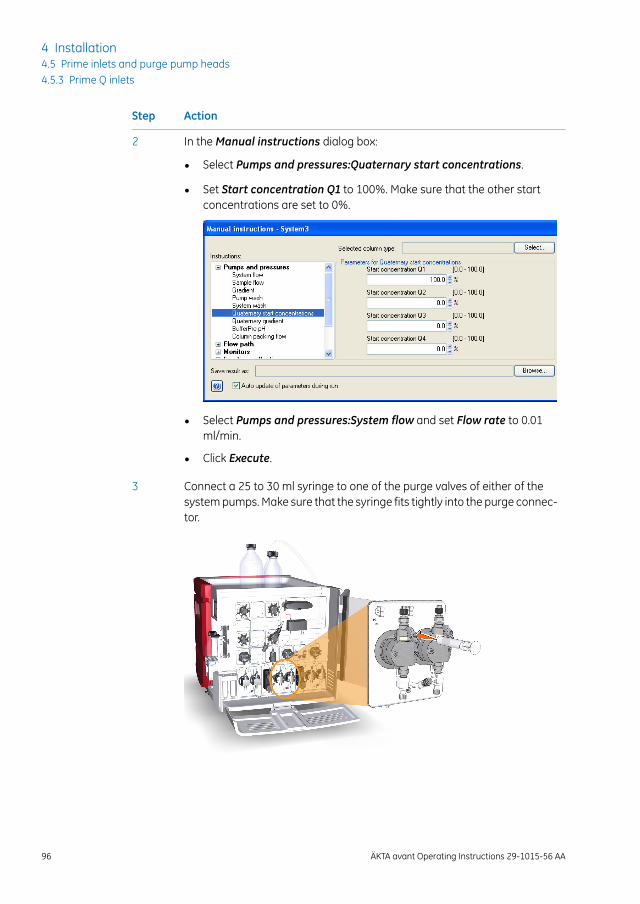
ActionStep
In the Manual instructions dialog box:2
• Select Pumps and pressures:Quaternary start concentrations.
• Set Start concentration Q1 to 100%. Make sure that the other startconcentrations are set to 0%.
• Select Pumps and pressures:System flow and set Flow rate to 0.01ml/min.
• Click Execute.
Connect a 25 to 30 ml syringe to one of the purge valves of either of thesystem pumps. Make sure that the syringe fits tightly into the purge connec-tor.
3
96 ÄKTA avant Operating Instructions 29-1015-56 AA
4 Installation4.5 Prime inlets and purge pump heads4.5.3 Prime Q inlets
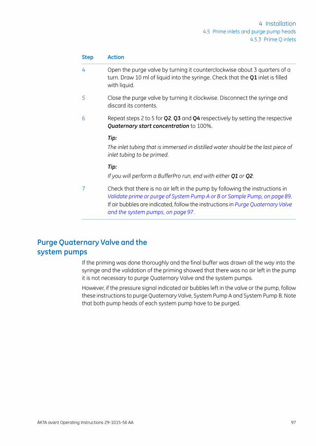
ActionStep
Open the purge valve by turning it counterclockwise about 3 quarters of aturn. Draw 10 ml of liquid into the syringe. Check that the Q1 inlet is filledwith liquid.
4
Close the purge valve by turning it clockwise. Disconnect the syringe anddiscard its contents.
5
Repeat steps 2 to 5 for Q2, Q3 and Q4 respectively by setting the respectiveQuaternary start concentration to 100%.
Tip:
The inlet tubing that is immersed in distilled water should be the last piece ofinlet tubing to be primed.
6
Tip:
If you will perform a BufferPro run, end with either Q1 or Q2.
Check that there is no air left in the pump by following the instructions inValidate prime or purge of System Pump A or B or Sample Pump, on page89.If air bubbles are indicated, follow the instructions in Purge Quaternary Valveand the system pumps, on page 97.
7
Purge Quaternary Valve and thesystem pumps
If the priming was done thoroughly and the final buffer was drawn all the way into thesyringe and the validation of the priming showed that there was no air left in the pumpit is not necessary to purge Quaternary Valve and the system pumps.
However, if the pressure signal indicated air bubbles left in the valve or the pump, followthese instructions to purge Quaternary Valve, System Pump A and System Pump B. Notethat both pump heads of each system pump have to be purged.
ÄKTA avant Operating Instructions 29-1015-56 AA 97
4 Installation4.5 Prime inlets and purge pump heads
4.5.3 Prime Q inlets
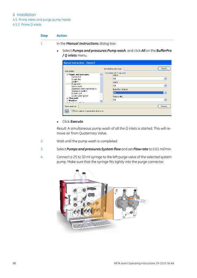
ActionStep
In the Manual instructions dialog box:1
• Select Pumps and pressures:Pumpwash, and clickAll on the BufferPro/ Q inlets menu.
• Click Execute.
Result: A simultaneous pump wash of all the Q inlets is started. This will re-move air from Quaternary Valve.
Wait until the pump wash is completed.2
Select Pumps and pressures:System flow and set Flow rate to 0.01 ml/min.3
Connect a 25 to 30 ml syringe to the left purge valve of the selected systempump. Make sure that the syringe fits tightly into the purge connector.
4
98 ÄKTA avant Operating Instructions 29-1015-56 AA
4 Installation4.5 Prime inlets and purge pump heads4.5.3 Prime Q inlets
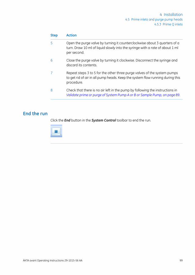
ActionStep
Open the purge valve by turning it counterclockwise about 3 quarters of aturn. Draw 10 ml of liquid slowly into the syringe with a rate of about 1 mlper second.
5
Close the purge valve by turning it clockwise. Disconnect the syringe anddiscard its contents.
6
Repeat steps 3 to 5 for the other three purge valves of the system pumpsto get rid of air in all pump heads. Keep the system flow running during thisprocedure.
7
Check that there is no air left in the pump by following the instructions inValidate prime or purge of System Pump A or B or Sample Pump, on page89.
8
End the runClick the End button in the System Control toolbar to end the run.
ÄKTA avant Operating Instructions 29-1015-56 AA 99
4 Installation4.5 Prime inlets and purge pump heads
4.5.3 Prime Q inlets

4.6 Performance tests
IntroductionBefore taking the ÄKTA avant instrument into use, run performance tests to check thefunction of the equipment. See ÄKTA avant User Manual for further instructions.
100 ÄKTA avant Operating Instructions 29-1015-56 AA
4 Installation4.6 Performance tests
5 Prepare the system for a run
About this chapterThis chapter describes the preparations necessary before starting a run.
In this chapterThis chapter contains the following sections:
See pageSection
1025.1 Before you prepare the system
1045.2 Prepare the flowpath
1095.3 Prime buffer inlets and purge system pumps
1105.4 Connect a column
1155.5 Set pressure alarms
1175.6 Calibrate the pH monitor
1195.7 Prepare the built-in fraction collector
1255.8 Prepare for a run at cold temperature
ÄKTA avant Operating Instructions 29-1015-56 AA 101
5 Prepare the system for a run
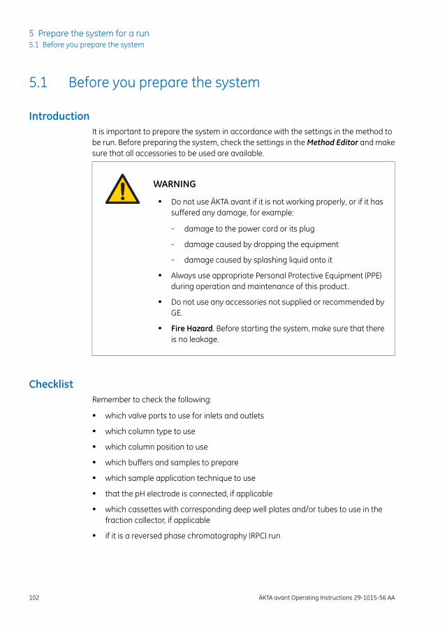
5.1 Before you prepare the system
IntroductionIt is important to prepare the system in accordance with the settings in the method tobe run. Before preparing the system, check the settings in the Method Editor and makesure that all accessories to be used are available.
WARNING
• Do not use ÄKTA avant if it is not working properly, or if it hassuffered any damage, for example:
- damage to the power cord or its plug
- damage caused by dropping the equipment
- damage caused by splashing liquid onto it
• Always use appropriate Personal Protective Equipment (PPE)during operation and maintenance of this product.
• Do not use any accessories not supplied or recommended byGE.
• Fire Hazard. Before starting the system, make sure that thereis no leakage.
ChecklistRemember to check the following:
• which valve ports to use for inlets and outlets
• which column type to use
• which column position to use
• which buffers and samples to prepare
• which sample application technique to use
• that the pH electrode is connected, if applicable
• which cassettes with corresponding deep well plates and/or tubes to use in thefraction collector, if applicable
• if it is a reversed phase chromatography (RPC) run
102 ÄKTA avant Operating Instructions 29-1015-56 AA
5 Prepare the system for a run5.1 Before you prepare the system
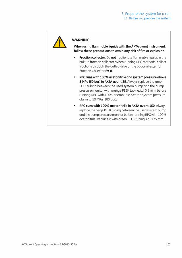
WARNINGWhenusing flammable liquidswith the ÄKTA avant instrument,follow these precautions to avoid any risk of fire or explosion.
• Fraction collector. Do not fractionate flammable liquids in thebuilt-in fraction collector. When running RPC methods, collectfractions through the outlet valve or the optional externalFraction Collector F9-R.
• RPC runswith 100%acetonitrile and systempressure above5 MPa (50 bar) in ÄKTA avant 25. Always replace the greenPEEK tubing between the used system pump and the pumppressure monitor with orange PEEK tubing, i.d. 0.5 mm, beforerunning RPC with 100% acetonitrile. Set the system pressurealarm to 10 MPa (100 bar).
• RPC runs with 100% acetonitrile in ÄKTA avant 150. Alwaysreplace the beige PEEK tubing between the used system pumpand the pump pressure monitor before running RPC with 100%acetonitrile. Replace it with green PEEK tubing, i.d. 0.75 mm.
ÄKTA avant Operating Instructions 29-1015-56 AA 103
5 Prepare the system for a run5.1 Before you prepare the system

5.2 Prepare the flowpath
IntroductionThe flow path contains tubing, valves, pumps and monitors. This section gives an overviewof the flow path and describes how to prepare the flow path before a run.
CAUTION
• Fasten bottles and cassettes. Always fasten bottles and cas-settes to the rails at the front and side panel. Use appropriateholders for bottles. Shattered glass from falling bottles maycause injury. Spilled liquid may cause fire hazard and personalinjury.
• Max. weight on buffer tray. Do not place containers with avolume of more than 10 liters each on the buffer tray. The totalallowed weight on the buffer tray is 40 kg.
• Avoid spillage and overflow. Make sure that the system isprepared according to the settings in the method to be run.For example make sure that the waste tubing is inserted in anappropriate waste container and secured in place.
104 ÄKTA avant Operating Instructions 29-1015-56 AA
5 Prepare the system for a run5.2 Prepare the flowpath
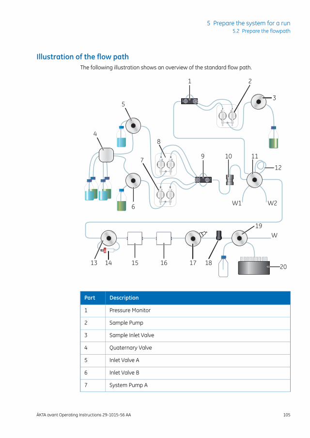
Illustration of the flow pathThe following illustration shows an overview of the standard flow path.
6
7
8
9 10 11
12
13 14 15 16 17
19
20
W1 W2
W
3
21
18
4
5
DescriptionPart
Pressure Monitor1
Sample Pump2
Sample Inlet Valve3
Quaternary Valve4
Inlet Valve A5
Inlet Valve B6
System Pump A7
ÄKTA avant Operating Instructions 29-1015-56 AA 105
5 Prepare the system for a run5.2 Prepare the flowpath
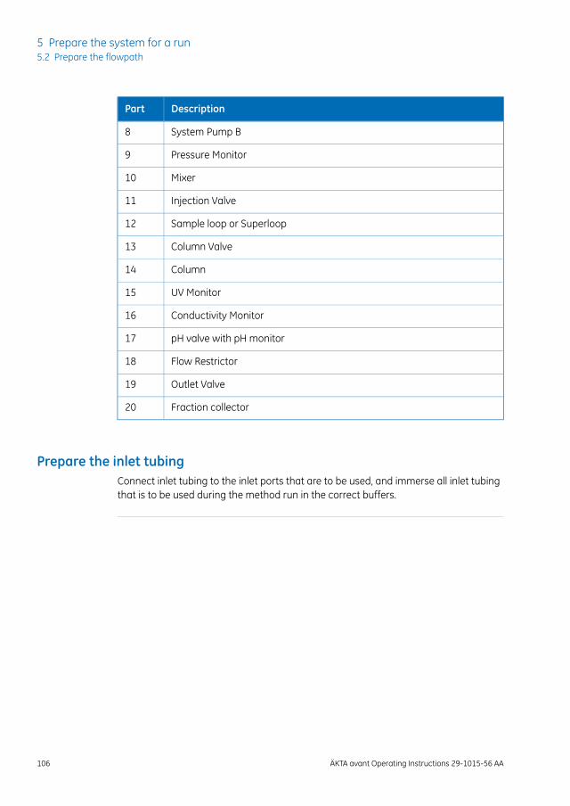
DescriptionPart
System Pump B8
Pressure Monitor9
Mixer10
Injection Valve11
Sample loop or Superloop12
Column Valve13
Column14
UV Monitor15
Conductivity Monitor16
pH valve with pH monitor17
Flow Restrictor18
Outlet Valve19
Fraction collector20
Prepare the inlet tubingConnect inlet tubing to the inlet ports that are to be used, and immerse all inlet tubingthat is to be used during the method run in the correct buffers.
106 ÄKTA avant Operating Instructions 29-1015-56 AA
5 Prepare the system for a run5.2 Prepare the flowpath
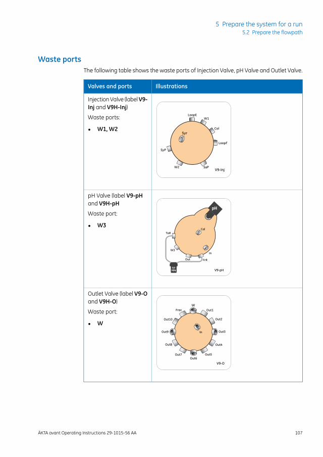
Waste portsThe following table shows the waste ports of Injection Valve, pH Valve and Outlet Valve.
IllustrationsValves and ports
Injection Valve (labelV9-Inj and V9H-Inj)
Waste ports:
• W1, W2
pH Valve (label V9-pHand V9H-pH
Waste port:
• W3
Outlet Valve (label V9-Oand V9H-O)
Waste port:
• W
ÄKTA avant Operating Instructions 29-1015-56 AA 107
5 Prepare the system for a run5.2 Prepare the flowpath
Prepare the waste tubingMake sure that the waste tubing is prepared according to the instructions in Section 4.2.3Prepare waste tubing, on page 70.
Prepare the outlet tubingConnect outlet tubing to the outlet ports of the outlet valve that are to be used duringthe run. If a fraction collector is to be used, make sure that tubing is connected betweenthe outlet valve Frac port and the fraction collector, and prepare the fraction collector.Otherwise, immerse the outlet tubing in suitable tubes or flasks.
Plug unused valve portsIt is recommended to plug all unused valve ports with stop plugs before starting a run.See ÄKTA avant User Manual for information about connectors.
108 ÄKTA avant Operating Instructions 29-1015-56 AA
5 Prepare the system for a run5.2 Prepare the flowpath
5.3 Prime buffer inlets and purge system pumps
IntroductionBefore you start the system pumps, it is important to do the following:
• Prime the inlets (fill the buffer inlets with liquid).
• Purge the system pumps (remove air from the pump heads).
For instructions on how to prime the inlets and purge the system pumps, see Section 4.5Prime inlets and purge pump heads, on page 82.
ÄKTA avant Operating Instructions 29-1015-56 AA 109
5 Prepare the system for a run5.3 Prime buffer inlets and purge system pumps
5.4 Connect a column
IntroductionThis section describes how to connect a column to the instrument using a columnholder and without introducing air into the flow path. Several types of column holdersare available for the ÄKTA avant instrument.
WARNINGBefore connecting to a column, read the instructions for use of thecolumn. To avoid exposing the column to excessive pressure, makesure that the pressure limit is set to the specified maximum pressurefor the column.
Methods automatically include a pressure alarm based on the specifications of thechosen column type. However, when running manual runs you have to set the pressurelimits yourself. Also, to protect the column media, special settings are needed. See Sec-tion 5.5 Set pressure alarms, on page 115 for more information on pressure alarms.
Do not overtighten when connecting columns. Overtightening might rupturethe connectors or squeeze the tubing and thereby result in high back pressure.
Note:
110 ÄKTA avant Operating Instructions 29-1015-56 AA
5 Prepare the system for a run5.4 Connect a column
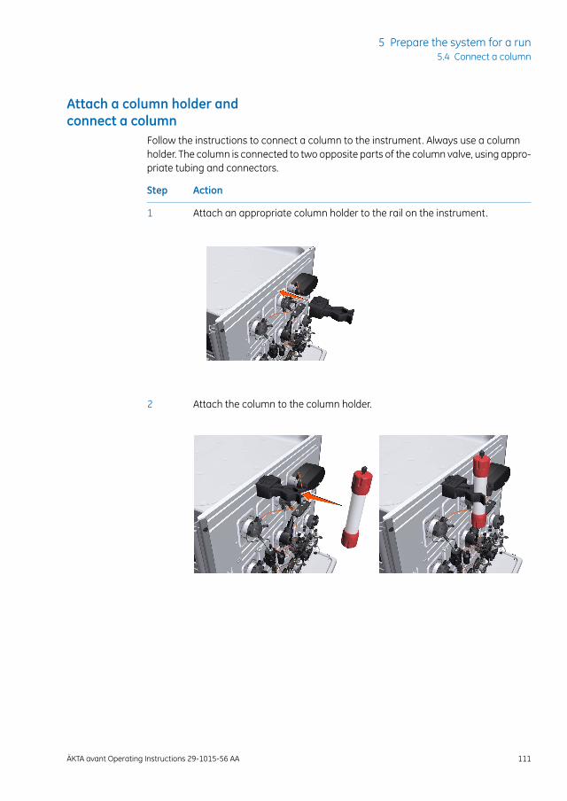
Attach a column holder andconnect a column
Follow the instructions to connect a column to the instrument. Always use a columnholder. The column is connected to two opposite parts of the column valve, using appro-priate tubing and connectors.
ActionStep
Attach an appropriate column holder to the rail on the instrument.1
Attach the column to the column holder.2
ÄKTA avant Operating Instructions 29-1015-56 AA 111
5 Prepare the system for a run5.4 Connect a column
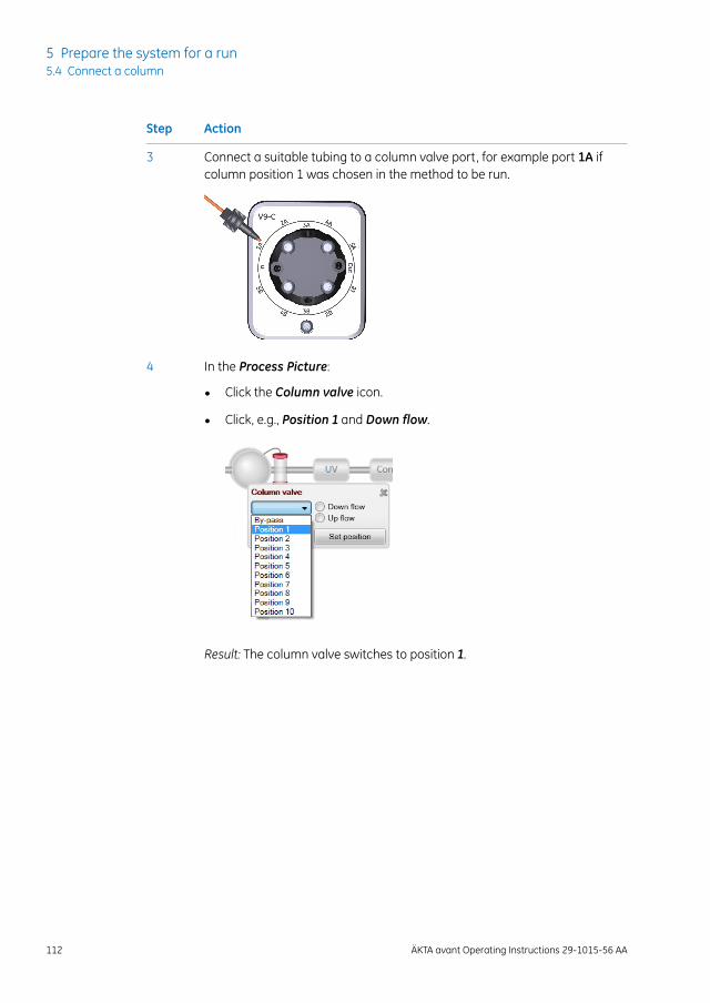
ActionStep
Connect a suitable tubing to a column valve port, for example port 1A ifcolumn position 1 was chosen in the method to be run.
3
In the Process Picture:4
• Click the Column valve icon.
• Click, e.g., Position 1 and Down flow.
Result: The column valve switches to position 1.
112 ÄKTA avant Operating Instructions 29-1015-56 AA
5 Prepare the system for a run5.4 Connect a column
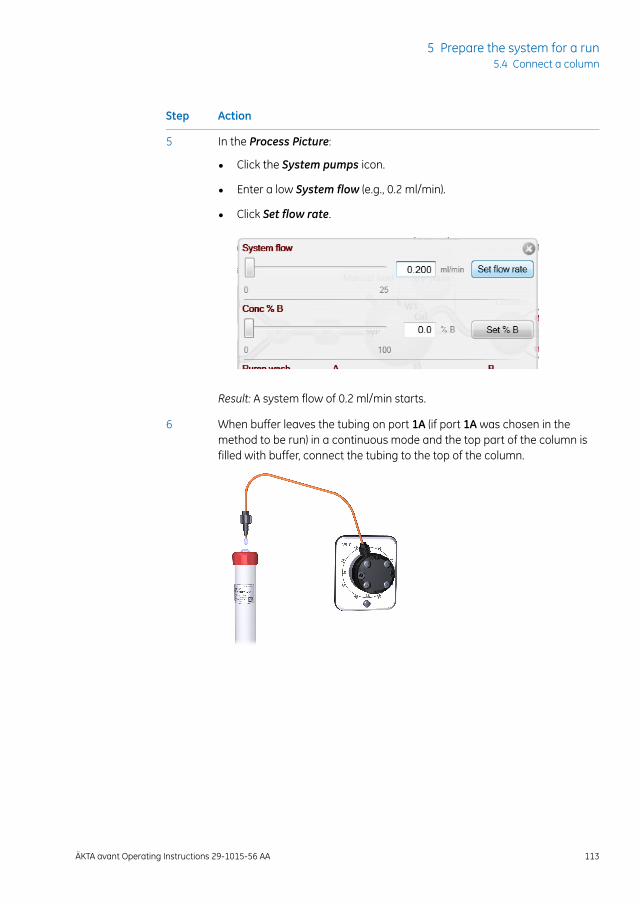
ActionStep
In the Process Picture:5
• Click the System pumps icon.
• Enter a low System flow (e.g., 0.2 ml/min).
• Click Set flow rate.
Result: A system flow of 0.2 ml/min starts.
When buffer leaves the tubing on port 1A (if port 1A was chosen in themethod to be run) in a continuous mode and the top part of the column isfilled with buffer, connect the tubing to the top of the column.
6
ÄKTA avant Operating Instructions 29-1015-56 AA 113
5 Prepare the system for a run5.4 Connect a column
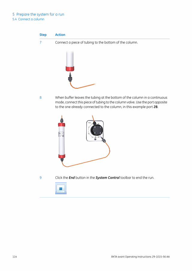
ActionStep
Connect a piece of tubing to the bottom of the column.7
When buffer leaves the tubing at the bottom of the column in a continuousmode, connect this piece of tubing to the column valve. Use the port oppositeto the one already connected to the column, in this example port 2B.
8
Click the End button in the System Control toolbar to end the run.9
114 ÄKTA avant Operating Instructions 29-1015-56 AA
5 Prepare the system for a run5.4 Connect a column
5.5 Set pressure alarms
IntroductionThe columns can be protected by two different types of pressure alarms:
• The precolumn pressure alarm protects the column hardware.
• The delta-column pressure alarm protects the column media.
Column Valve (label V9-C and V9H-C) have built-in pressure sensors that automaticallymeasure the precolumn and delta-column pressure.
See the instructions in the next topic to set the pressure alarm for the column to be usedin the run and, if applicable, to set the parameters for the tubing dimensions.
Remember to lower the system pressure alarm and sample pressure alarm ifthe optional UVMonitorU9-L and/or the optional second ConductivityMonitorC9 is used on the high pressure side in the system (before the column[s]). TheUV Monitor U9-L flow cells has a maximum pressure limit of 2 MPa (20 bar)and the second Conductivity Monitor C9 flow cell has a maximum pressurelimit of 5 MPa (50 bar).
Note:
NOTICEUV and conductivity flow cells on the high pressure side. Whenplacing UV and/or conductivity flow cells on the high pressure sideof the column, the UV flow cell has a maximum pressure limit of 2MPa (20 bar) and the conductivity flow cell has a maximum pressurelimit of 5 MPa (50 bar).
NOTICERemember to lower the system pressure alarm and sample pres-sure alarm if the optional UV Monitor U9-L and/or the optionalsecond Conductivity Monitor C9 is used on the high pressure sidein the system (before the column[s]). The UV MonitorU9-L flow cellshas a maximum pressure limit of 2.0 MPa (20 bar) and the secondConductivity Monitor C9 flow cell has a maximum pressure limit of5.0 MPa (50 bar).
ÄKTA avant Operating Instructions 29-1015-56 AA 115
5 Prepare the system for a run5.5 Set pressure alarms
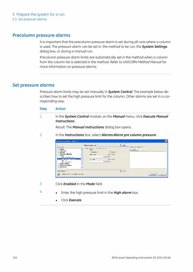
Precolumn pressure alarmsIt is important that the precolumn pressure alarm is set during all runs where a columnis used. The pressure alarm can be set in: the method to be run, the System Settingsdialog box, or during a manual run.
Precolumn pressure alarm limits are automatically set in the method when a columnfrom the column list is selected in the method. Refer to UNICORN Method Manual formore information on pressure alarms.
Set pressure alarmsPressure alarm limits may be set manually in System Control. The example below de-scribes how to set the high pressure limit for the column. Other alarms are set in a cor-responding way.
ActionStep
In the System Control module, on the Manual menu, click Execute ManualInstructions .
1
Result: The Manual instructions dialog box opens.
In the Instructions box, select Alarms:Alarm pre column pressure.2
Click Enabled in the Mode field.3
• Enter the high pressure limit in the High alarm box.
• Click Execute.
4
116 ÄKTA avant Operating Instructions 29-1015-56 AA
5 Prepare the system for a run5.5 Set pressure alarms
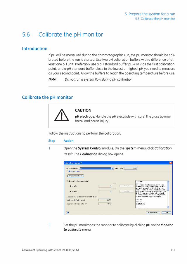
5.6 Calibrate the pH monitor
IntroductionIf pH will be measured during the chromatographic run, the pH monitor should be cali-brated before the run is started. Use two pH calibration buffers with a difference of atleast one pH unit. Preferably use a pH standard buffer pH 4 or 7 as the first calibrationpoint, and a pH standard buffer close to the lowest or highest pH you need to measureas your second point. Allow the buffers to reach the operating temperature before use.
Do not run a system flow during pH calibration.Note:
Calibrate the pH monitor
CAUTIONpHelectrode. Handle the pH electrode with care. The glass tip maybreak and cause injury.
Follow the instructions to perform the calibration.
ActionStep
Open the System Control module. On the System menu, click Calibration.1
Result: The Calibration dialog box opens.
Set the pH monitor as the monitor to calibrate by clicking pH on theMonitorto calibrate menu.
2
ÄKTA avant Operating Instructions 29-1015-56 AA 117
5 Prepare the system for a run5.6 Calibrate the pH monitor
ActionStep
Click Prepare for calibration.3
Result: The pH valve switches to the calibration position.
Enter the pH of the first pH standard buffer in the pH for buffer 1 box.4
Fill a syringe with approximately 10 ml of the first pH standard buffer. Con-nect the syringe to the Luer connector in pH valve port Cal, and inject thebuffer.
5
When the Current value is stable, click Calibrate.6
Wash the pH flow cell by injecting water into pH valve port Cal using a newsyringe.
7
Enter the pH of the second pH standard buffer in the pH for buffer 2 box.8
Repeat steps 5 to 6 using the second pH standard buffer.9
Result: The calibration date and time are displayed in the dialog box, andalso values for Calibrated electrode slope and Asymmetry potential at pH7.
Is the Calibrated electrode slope ≥ 80% and the Asymmetry potential atpH 7 inside the interval ±60 mV?
10
• If Yes: Click Close to switch the pH valve back to the default position,and to close the Calibration dialog box.
• If No: Clean the pH electrode, and repeat the calibration procedure. Ifthis does not help, replace the electrode. For information about cleaningand replacing the pH electrode, see ÄKTA avant User Manual ChapterMaintenance.
118 ÄKTA avant Operating Instructions 29-1015-56 AA
5 Prepare the system for a run5.6 Calibrate the pH monitor
5.7 Prepare the built-in fraction collector
IntroductionThis section describes how to prepare the built-in raction collector. For information re-garding the types of deep well plates, tubes and cassettes, see ÄKTA avant User Manual.
WARNINGFraction collector. Do not fractionate flammable liquids in thebuilt-in fraction collector. When running RPC methods, collectfractions through the outlet valve or the optional external FractionCollector F9-R.
Prepare the fraction collectorBefore starting to prepare the built-in fraction collector, check the fractionation settingsin the method to be run. Perform the steps described below according to the settings inthe method.
• Insert the cassette tray or a rack for tubes or bottles.
• Change the System Settings in UNICORN to set the fractionation mode and othersettings for fraction collection.
How to insert a tray or a rack is shown in the following topic.
For information on how to change the System Settings before a run, see UNICORNSystem Control Manual. The available System Settings are described in ÄKTA avant UserManual.
ÄKTA avant Operating Instructions 29-1015-56 AA 119
5 Prepare the system for a run5.7 Prepare the built-in fraction collector
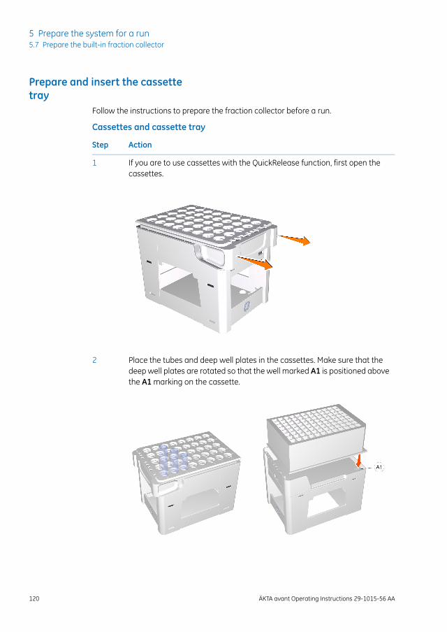
Prepare and insert the cassettetray
Follow the instructions to prepare the fraction collector before a run.
Cassettes and cassette tray
ActionStep
If you are to use cassettes with the QuickRelease function, first open thecassettes.
1
Place the tubes and deep well plates in the cassettes. Make sure that thedeep well plates are rotated so that the well marked A1 is positioned abovethe A1 marking on the cassette.
2
120 ÄKTA avant Operating Instructions 29-1015-56 AA
5 Prepare the system for a run5.7 Prepare the built-in fraction collector

ActionStep
Close the cassettes that have the QuickRelease function.3
Place the cassettes on the cassette tray. Make sure that the cassette typecode (see the illustration) faces the front of the tray marked with the GEmonogram.
4
Open the fraction collector drawer by pressing the handle upwards, andpulling out the drawer.
5
ÄKTA avant Operating Instructions 29-1015-56 AA 121
5 Prepare the system for a run5.7 Prepare the built-in fraction collector
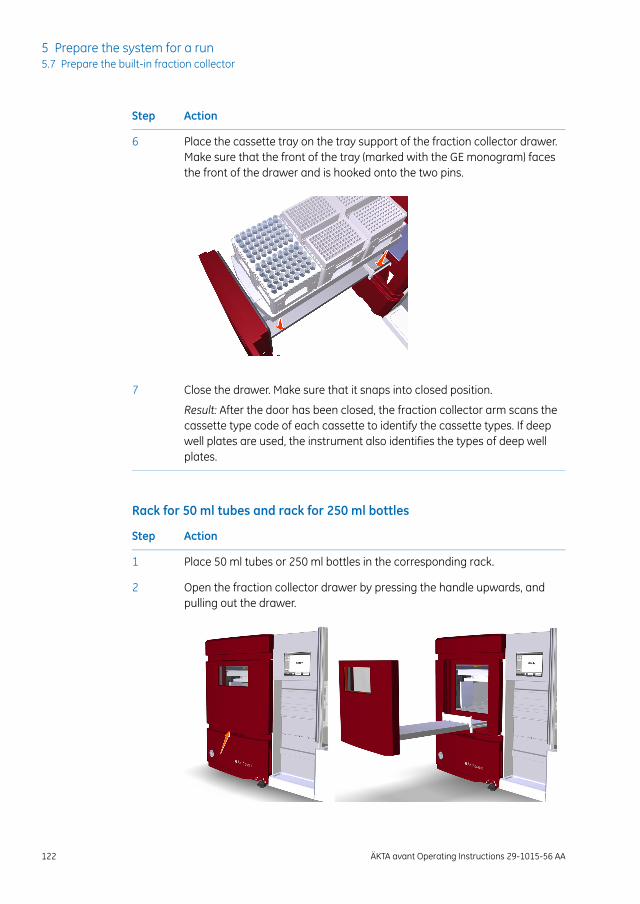
ActionStep
Place the cassette tray on the tray support of the fraction collector drawer.Make sure that the front of the tray (marked with the GE monogram) facesthe front of the drawer and is hooked onto the two pins.
6
Close the drawer. Make sure that it snaps into closed position.7
Result: After the door has been closed, the fraction collector arm scans thecassette type code of each cassette to identify the cassette types. If deepwell plates are used, the instrument also identifies the types of deep wellplates.
Rack for 50 ml tubes and rack for 250 ml bottles
ActionStep
Place 50 ml tubes or 250 ml bottles in the corresponding rack.1
Open the fraction collector drawer by pressing the handle upwards, andpulling out the drawer.
2
122 ÄKTA avant Operating Instructions 29-1015-56 AA
5 Prepare the system for a run5.7 Prepare the built-in fraction collector
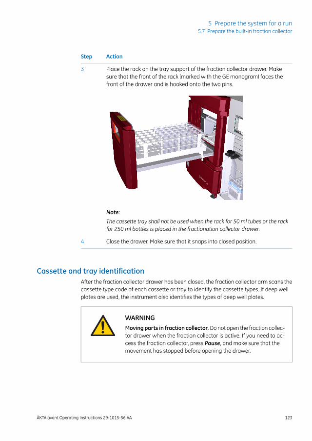
ActionStep
Place the rack on the tray support of the fraction collector drawer. Makesure that the front of the rack (marked with the GE monogram) faces thefront of the drawer and is hooked onto the two pins.
3
Note:
The cassette tray shall not be used when the rack for 50 ml tubes or the rackfor 250 ml bottles is placed in the fractionation collector drawer.
Close the drawer. Make sure that it snaps into closed position.4
Cassette and tray identificationAfter the fraction collector drawer has been closed, the fraction collector arm scans thecassette type code of each cassette or tray to identify the cassette types. If deep wellplates are used, the instrument also identifies the types of deep well plates.
WARNINGMoving parts in fraction collector. Do not open the fraction collec-tor drawer when the fraction collector is active. If you need to ac-cess the fraction collector, press Pause, and make sure that themovement has stopped before opening the drawer.
ÄKTA avant Operating Instructions 29-1015-56 AA 123
5 Prepare the system for a run5.7 Prepare the built-in fraction collector
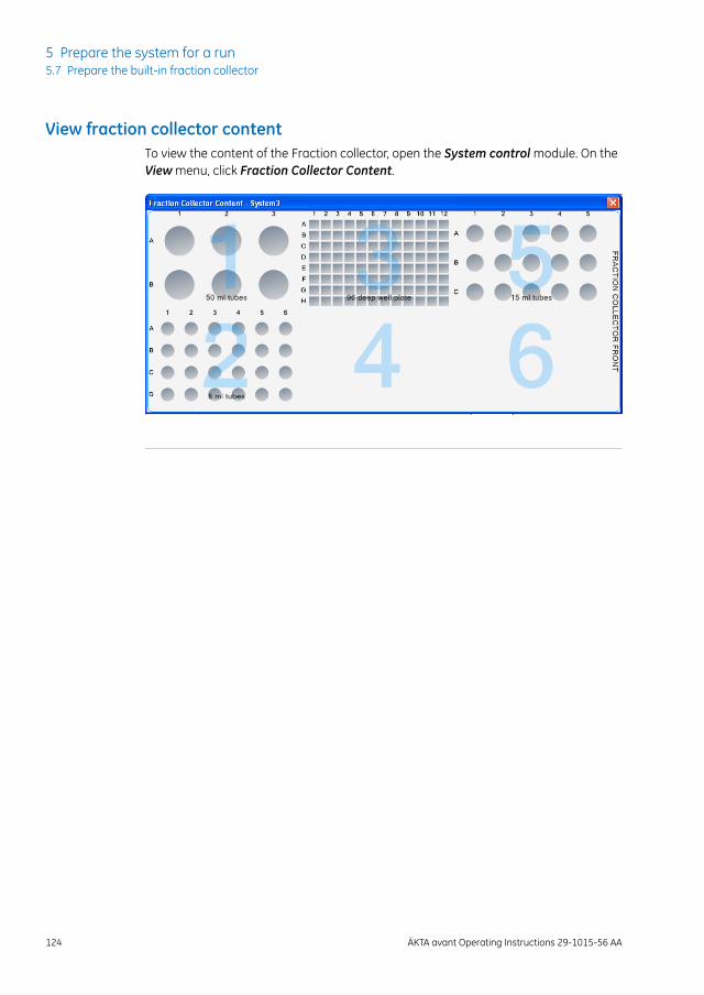
View fraction collector contentTo view the content of the Fraction collector, open the System control module. On theView menu, click Fraction Collector Content.
124 ÄKTA avant Operating Instructions 29-1015-56 AA
5 Prepare the system for a run5.7 Prepare the built-in fraction collector
5.8 Prepare for a run at cold temperature
IntroductionTo fit the ÄKTA avant instrument in a cold cabinet, the foldable door and pump covercan be removed. For instructions, seeÄKTAavantUserManual. When using the instrumentin a cold room or cold cabinet, make sure to follow the precautions listed in the nexttopic.
Precautions concerning runs ina cold temperature
NOTICE
• Avoid condensation. If ÄKTA avant is kept in a cold room, coldcabinet or similar, keep it switched on in order to avoid conden-sation.
• Avoid overheating. If ÄKTA avant is kept in a cold cabinet andthe cold cabinet is switched off, make sure to switch off ÄKTAavant and keep the cold cabinet open to avoid overheating.
• Place the computer in room temperature. If the ÄKTA avantinstrument is placed in a cold room, use a cold room compat-ible computer or place the computer outside the cold roomand use the Ethernet cable delivered with the instrument toconnect to the computer.
When the instrument is kept in a cold room, it is important to tighten all tubingconnectors, also the inlet manifold connectors. Otherwise air might get intothe flow path.
Note:
Make sure that the instrument, buffers and sample have had time to reachthe ambient temperature. When the instrument has reached the ambienttemperature, calibrate all pressure sensors.
Note:
When runs are performed in a cold cabinet, make sure to adjust the targettemperature of the built-in fraction collector temperature control function. Thetarget temperature is 20°C by default. Settings for the temperature controlfunction can be edited in the System Settings dialog box of System Control,or in the Text Instructions pane inMethod Editor.
Tip:
ÄKTA avant Operating Instructions 29-1015-56 AA 125
5 Prepare the system for a run5.8 Prepare for a run at cold temperature
6 Run a method
About this chapterThis chapter describes how to start up and run a method, and also how to handle thesystem after the run.
In this chapterThis chapter contains the following sections:
See pageSection
1276.1 Before you start
1306.2 Applying the sample
1336.3 Start a method run
1396.4 Monitor the run
1426.5 After run procedures
126 ÄKTA avant Operating Instructions 29-1015-56 AA
6 Run a method
6.1 Before you start
IntroductionBefore starting a run, it is necessary to read and understand the information in thissection and to perform the checks listed in the next topic.
WARNING
• Always use appropriate Personal Protective Equipment (PPE)during operation and maintenance of this product.
• Hazardous substances. When using hazardous chemicals,take all suitable protective measures, such as wearing protec-tive glasses and gloves resistant to the substances used. Followlocal and/or national regulations for safe operation andmaintenance of the product.
• High pressure. The product operates under high pressure.Wear protective glasses and other required Personal ProtectiveEquipment (PPE) at all times.
ChecklistMake sure that the system is correctly prepared:
• Prepared the system according to the settings in the method to be run.
• Select a suitable column for the application.
• Immerse the buffer inlet tubing in correct buffer vessels.
• Immerse all waste tubing in appropriate waste vessels (consider vessel size, placementand material).
• Make sure no tubing is twisted and that the flow path is free from leakage.
ÄKTA avant Operating Instructions 29-1015-56 AA 127
6 Run a method6.1 Before you start
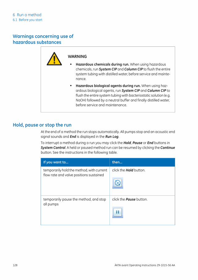
Warnings concerning use ofhazardous substances
WARNING
• Hazardous chemicals during run. When using hazardouschemicals, run System CIP and Column CIP to flush the entiresystem tubing with distilled water, before service and mainte-nance.
• Hazardous biological agents during run. When using haz-ardous biological agents, run System CIP and Column CIP toflush the entire system tubing with bacteriostatic solution (e.g.NaOH) followed by a neutral buffer and finally distilled water,before service and maintenance.
Hold, pause or stop the runAt the end of a method the run stops automatically. All pumps stop and an acoustic endsignal sounds and End is displayed in the Run Log.
To interrupt a method during a run you may click the Hold, Pause or End buttons inSystem Control. A held or paused method run can be resumed by clicking the Continuebutton. See the instructions in the following table.
then...If you want to...
click the Hold button.temporarily hold the method, with currentflow rate and valve positions sustained
click the Pause button.temporarily pause the method, and stopall pumps
128 ÄKTA avant Operating Instructions 29-1015-56 AA
6 Run a method6.1 Before you start
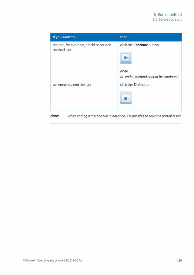
then...If you want to...
click the Continue button.resume, for example, a held or pausedmethod run.
Note:
An ended method cannot be continued.
click the End button.permanently end the run
When ending amethod run in advance, it is possible to save the partial result.Note:
ÄKTA avant Operating Instructions 29-1015-56 AA 129
6 Run a method6.1 Before you start
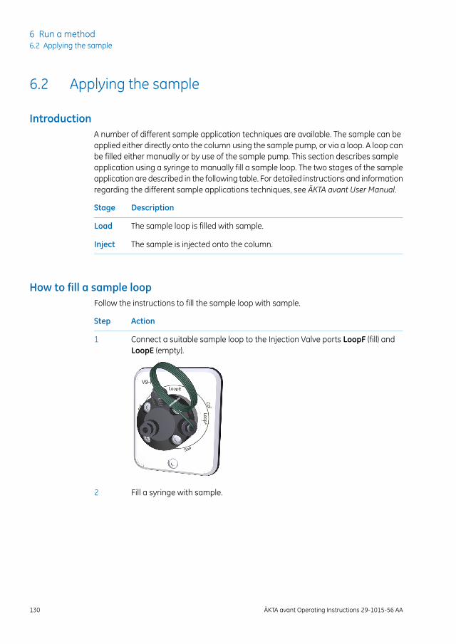
6.2 Applying the sample
IntroductionA number of different sample application techniques are available. The sample can beapplied either directly onto the column using the sample pump, or via a loop. A loop canbe filled either manually or by use of the sample pump. This section describes sampleapplication using a syringe to manually fill a sample loop. The two stages of the sampleapplication are described in the following table. For detailed instructions and informationregarding the different sample applications techniques, see ÄKTA avant User Manual.
DescriptionStage
The sample loop is filled with sample.Load
The sample is injected onto the column.Inject
How to fill a sample loopFollow the instructions to fill the sample loop with sample.
ActionStep
Connect a suitable sample loop to the Injection Valve ports LoopF (fill) andLoopE (empty).
1
Fill a syringe with sample.2
130 ÄKTA avant Operating Instructions 29-1015-56 AA
6 Run a method6.2 Applying the sample
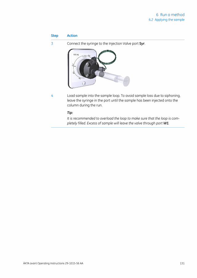
ActionStep
Connect the syringe to the Injection Valve port Syr.3
Load sample into the sample loop. To avoid sample loss due to siphoning,leave the syringe in the port until the sample has been injected onto thecolumn during the run.
Tip:
It is recommended to overload the loop to make sure that the loop is com-pletely filled. Excess of sample will leave the valve through portW1.
4
ÄKTA avant Operating Instructions 29-1015-56 AA 131
6 Run a method6.2 Applying the sample
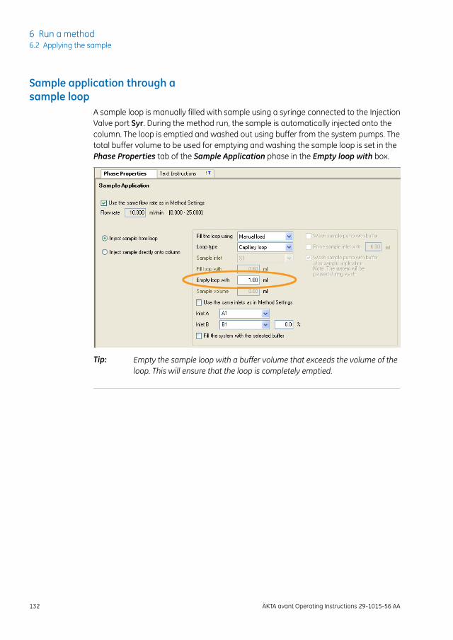
Sample application through asample loop
A sample loop is manually filled with sample using a syringe connected to the InjectionValve port Syr. During the method run, the sample is automatically injected onto thecolumn. The loop is emptied and washed out using buffer from the system pumps. Thetotal buffer volume to be used for emptying and washing the sample loop is set in thePhase Properties tab of the Sample Application phase in the Empty loop with box.
Empty the sample loop with a buffer volume that exceeds the volume of theloop. This will ensure that the loop is completely emptied.
Tip:
132 ÄKTA avant Operating Instructions 29-1015-56 AA
6 Run a method6.2 Applying the sample

6.3 Start a method run
IntroductionThis section describes how to start a run using a previously created method. If ColumnLogbook was enabled during installation of the software, registration and selection ofindividual columns is possible at method start. For further information on method creation,please refer to UNICORN Method Manual.
Choose and start a methodThe following instructions describe how to open a method and start a run.
ActionStep
Open the System Control module and click the Open Method Navigatorbutton.
1
Result: The Method Navigator pane opens.
Select the method to run, and click the Run button.2
Result: The Start Protocol dialog box opens.
Step through the displayed pages in the Start Protocol, add requested inputand make appropriate changes if necessary. Click Next.
3
ÄKTA avant Operating Instructions 29-1015-56 AA 133
6 Run a method6.3 Start a method run
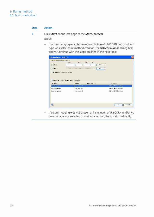
ActionStep
Click Start on the last page of the Start Protocol.4
Result:
• If column logging was chosen at installation of UNICORN and a columntype was selected at method creation, the Select Columns dialog boxopens. Continue with the steps outlined in the next topic.
• If column logging was not chosen at installation of UNICORN and/or nocolumn type was selected at method creation, the run starts directly.
134 ÄKTA avant Operating Instructions 29-1015-56 AA
6 Run a method6.3 Start a method run
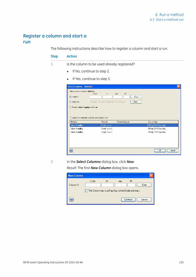
Register a column and start arun
The following instructions describe how to register a column and start a run.
ActionStep
Is the column to be used already registered?1
• If No, continue to step 2.
• If Yes, continue to step 5.
In the Select Columns dialog box, click New.2
Result: The first New Column dialog box opens.
ÄKTA avant Operating Instructions 29-1015-56 AA 135
6 Run a method6.3 Start a method run

ActionStep
Register the column using the Barcode Scanner 2-D as follows:3
• Make sure that the pointer is placed in the first position of the Code box.
• Point the Barcode Scanner 2-D towards the data matrix tag on the col-umn.
• Press and hold the trigger to create a beam.
• When the scanner beeps, the column ID is registered and displayed inthe dialog box.
• Alternatively, manually enter the column ID, that you find on the columnlabel, in the dialog box using your keyboard.
• Click Continue.
Result: The expanded New Column dialog box opens.
136 ÄKTA avant Operating Instructions 29-1015-56 AA
6 Run a method6.3 Start a method run
ActionStep
In the expanded New Column dialog box:4
• Enter an column alias in the Alias box (optional).
• Click a chromatography technique on the Technique menu.
• Click a column type on the Column type menu.
• Select the Set medium expiration date check box and click a date onthe menu.
• Click OK.
Tip:
Alias can be used for easy identification of a column.
Result: The entered information is saved and the dialog box closes.
ÄKTA avant Operating Instructions 29-1015-56 AA 137
6 Run a method6.3 Start a method run

ActionStep
In the Select Columns dialog box:5
• Click Enter ID.
• Use the Barcode Scanner 2-D (see step 3) to enter the column ID.
• Alternatively, click Select ID and click the column individual to be usedin the run from the menu.
• Click OK.
Result: The run starts. All necessary actions occur automatically accordingto the method, including ending of the run.
138 ÄKTA avant Operating Instructions 29-1015-56 AA
6 Run a method6.3 Start a method run
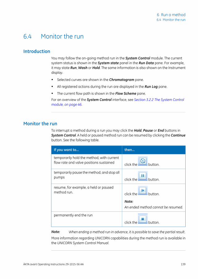
6.4 Monitor the run
IntroductionYou may follow the on-going method run in the System Control module. The currentsystem status is shown in the System state panel in the Run Data pane. For example,it may state Run, Wash or Hold. The same information is also shown on the Instrumentdisplay.
• Selected curves are shown in the Chromatogram pane.
• All registered actions during the run are displayed in the Run Log pane.
• The current flow path is shown in the Flow Scheme pane.
For an overview of the System Control interface, see Section 3.2.2 The System Controlmodule, on page 46.
Monitor the runTo interrupt a method during a run you may click the Hold, Pause or End buttons inSystem Control. A held or paused method run can be resumed by clicking the Continuebutton. See the following table.
then...If you want to...
click the button.
temporarily hold the method, with currentflow rate and valve positions sustained
click the button.
temporarily pause the method, and stop allpumps
click the button.
Note:
An ended method cannot be resumed.
resume, for example, a held or pausedmethod run.
click the button.
permanently end the run
When ending amethod run in advance, it is possible to save the partial result.Note:
More information regarding UNICORN capabilities during the method run is available inthe UNICORN System Control Manual.
ÄKTA avant Operating Instructions 29-1015-56 AA 139
6 Run a method6.4 Monitor the run
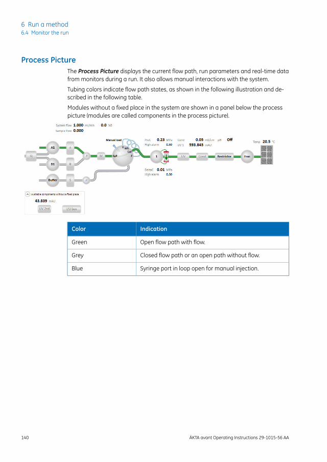
Process PictureThe Process Picture displays the current flow path, run parameters and real-time datafrom monitors during a run. It also allows manual interactions with the system.
Tubing colors indicate flow path states, as shown in the following illustration and de-scribed in the following table.
Modules without a fixed place in the system are shown in a panel below the processpicture (modules are called components in the process picture).
IndicationColor
Open flow path with flow.Green
Closed flow path or an open path without flow.Grey
Syringe port in loop open for manual injection.Blue
140 ÄKTA avant Operating Instructions 29-1015-56 AA
6 Run a method6.4 Monitor the run
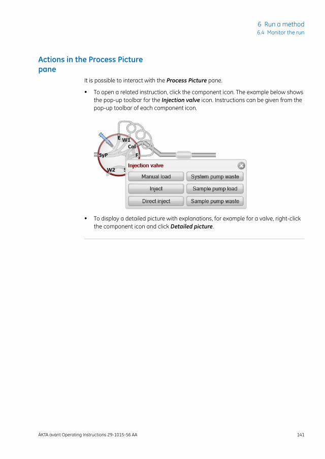
Actions in the Process Picturepane
It is possible to interact with the Process Picture pane.
• To open a related instruction, click the component icon. The example below showsthe pop-up toolbar for the Injection valve icon. Instructions can be given from thepop-up toolbar of each component icon.
• To display a detailed picture with explanations, for example for a valve, right-clickthe component icon and click Detailed picture.
ÄKTA avant Operating Instructions 29-1015-56 AA 141
6 Run a method6.4 Monitor the run
6.5 After run procedures
IntroductionThis section describes how to clean the instrument and columns after a chromatographicrun, and how to prepare the system for storage.
The instrument and the columns should be cleaned between the runs. This will prevent,for example, sample contamination, protein precipitation and column clogging. If theinstrument is not going to be used for a couple of days or longer, the instrument, columnsand the pH flow cell should be filled with storage solution. For further information aboutcleaning and maintenance procedures, see Chapter 7 Maintenance, on page 145.
To clean and fill the instrument and columns with storage solution, use theSystemCIP andColumnCIPmethods. Either as separate, predefinedmethodsor as phases included in a chromatographic method.
Tip:
WARNINGCorrosive chemicals duringmaintenance. If the system or columnis cleaned with a strong base or acid, flush with water afterwardsand wash with a weak neutral buffer solution in the last step orphase.
System cleaningAfter a method run is completed, perform the following:
• Rinse the instrument with one or several cleaning solution(s) (e.g., NaOH, buffer solu-tion or distilled water) using the System CIP method.
• If applicable, empty the fraction collector.
• Clean all spills on the instrument and on the bench using a moist tissue.
• Empty the waste vessel.
• Clean the manual injection port of the injection valve, see ÄKTA avant User Manualfor detailed instructions.
• If applicable, clean the pH electrode manually and make sure to leave it in an appro-priate buffer. See ÄKTA avant User Manual for detailed instructions.
142 ÄKTA avant Operating Instructions 29-1015-56 AA
6 Run a method6.5 After run procedures
System storageIf the instrument is not going to be used for a couple of days or longer, also perform thefollowing:
• Fill the system and inlets with storage solution (e.g., 20% ethanol) using the SystemCIP method.
Column cleaningAfter a method run is completed, perform the following:
• Clean the column with one or several cleaning solution(s) using the Column CIPmethod.
Column storageIf the column is not going to be used for a couple of days or longer, also perform thefollowing:
• Fill the column with storage solution (e.g., 20% ethanol) using theColumnCIPmethod.
pH electrode storageIf pH monitoring will not be used for a week or longer, perform one of the following ac-tions:
• Inject new storage solution into the pH flow cell.
• Replace the pH electrode with the dummy electrode that is installed in the pH valveon delivery.
In the following situations, in order to increase the lifetime of the pH electrode, use theBy-pass position and store the electrode in storage solution inside the pH flow cell:
• pH monitoring is not needed during the run.
• Organic solutions are used.
• Extremely acidic or extremely basic solutions are used.
For further information on how to prepare the pH electrode for storage, refer to ÄKTAavant User Manual.
ÄKTA avant Operating Instructions 29-1015-56 AA 143
6 Run a method6.5 After run procedures
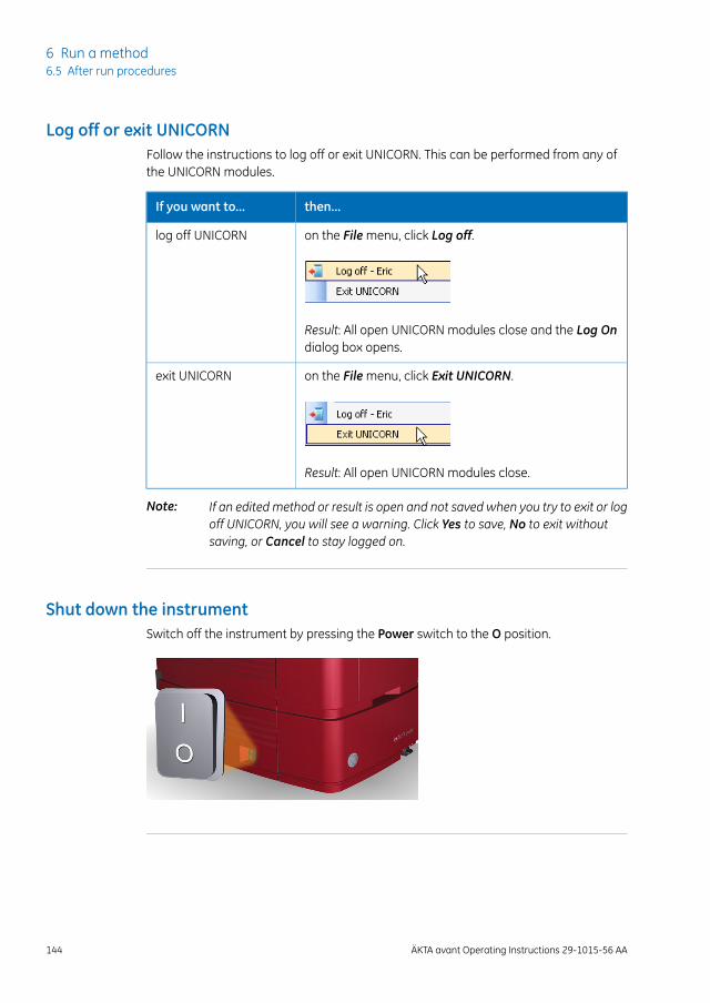
Log off or exit UNICORNFollow the instructions to log off or exit UNICORN. This can be performed from any ofthe UNICORN modules.
then...If you want to...
on the File menu, click Log off.log off UNICORN
Result: All open UNICORN modules close and the Log Ondialog box opens.
on the File menu, click Exit UNICORN.exit UNICORN
Result: All open UNICORN modules close.
If an edited method or result is open and not saved when you try to exit or logoff UNICORN, you will see a warning. Click Yes to save, No to exit withoutsaving, or Cancel to stay logged on.
Note:
Shut down the instrumentSwitch off the instrument by pressing the Power switch to the O position.
144 ÄKTA avant Operating Instructions 29-1015-56 AA
6 Run a method6.5 After run procedures
7 Maintenance
About this chapterThis chapter provides schedules for preventive maintenance that should be performedby the user of the ÄKTA avant instrument. Regular maintenance is essential for reliablefunction and results. Refer to the ÄKTA avant User Manual for detailed instructions. Pro-cedures that require special attention are also described in this chapter.
WARNINGAlways use appropriate Personal Protective Equipment (PPE) duringoperation and maintenance of this product.
In this chapterThis chapter contains the following sections:
See pageSection
1467.1 Maintenance program
1497.2 Replace pump piston seal, O-rings, and rinse membrane of PumpP9 or Pump P9H
1607.3 Replace pump piston seal, O-ring, and rinse membrane of PumpP9-S
1687.4 Replace pump pistons
1707.5 Clean pump head check valves
ÄKTA avant Operating Instructions 29-1015-56 AA 145
7 Maintenance
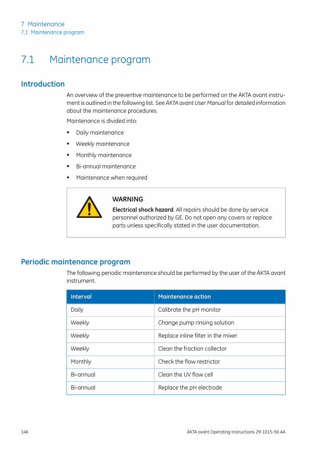
7.1 Maintenance program
IntroductionAn overview of the preventive maintenance to be performed on the ÄKTA avant instru-ment is outlined in the following list. SeeÄKTA avant UserManual for detailed informationabout the maintenance procedures.
Maintenance is divided into:
• Daily maintenance
• Weekly maintenance
• Monthly maintenance
• Bi-annual maintenance
• Maintenance when required
WARNINGElectrical shock hazard. All repairs should be done by servicepersonnel authorized by GE. Do not open any covers or replaceparts unless specifically stated in the user documentation.
Periodic maintenance programThe following periodic maintenance should be performed by the user of the ÄKTA avantinstrument.
Maintenance actionInterval
Calibrate the pH monitorDaily
Change pump rinsing solutionWeekly
Replace inline filter in the mixerWeekly
Clean the fraction collectorWeekly
Check the flow restrictorMonthly
Clean the UV flow cellBi-annual
Replace the pH electrodeBi-annual
146 ÄKTA avant Operating Instructions 29-1015-56 AA
7 Maintenance7.1 Maintenance program
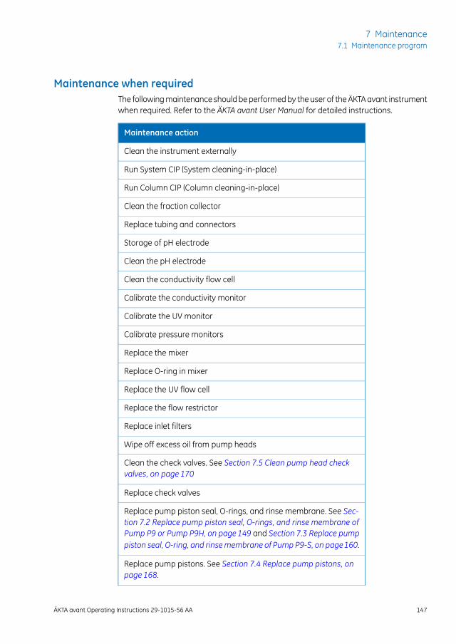
Maintenance when requiredThe following maintenance should be performed by the user of the ÄKTA avant instrumentwhen required. Refer to the ÄKTA avant User Manual for detailed instructions.
Maintenance action
Clean the instrument externally
Run System CIP (System cleaning-in-place)
Run Column CIP (Column cleaning-in-place)
Clean the fraction collector
Replace tubing and connectors
Storage of pH electrode
Clean the pH electrode
Clean the conductivity flow cell
Calibrate the conductivity monitor
Calibrate the UV monitor
Calibrate pressure monitors
Replace the mixer
Replace O-ring in mixer
Replace the UV flow cell
Replace the flow restrictor
Replace inlet filters
Wipe off excess oil from pump heads
Clean the check valves. See Section 7.5 Clean pump head checkvalves, on page 170
Replace check valves
Replace pump piston seal, O-rings, and rinse membrane. See Sec-tion 7.2 Replace pump piston seal, O-rings, and rinse membrane ofPump P9 or Pump P9H, on page149 and Section 7.3 Replace pumppiston seal, O-ring, and rinsemembrane of Pump P9-S, on page160.
Replace pump pistons. See Section 7.4 Replace pump pistons, onpage 168.
ÄKTA avant Operating Instructions 29-1015-56 AA 147
7 Maintenance7.1 Maintenance program
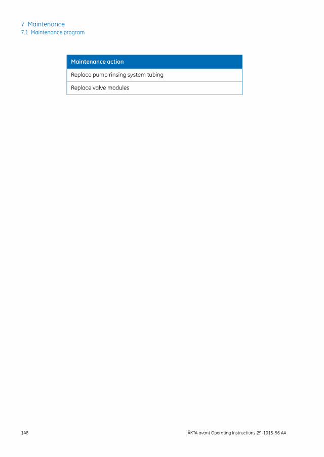
Maintenance action
Replace pump rinsing system tubing
Replace valve modules
148 ÄKTA avant Operating Instructions 29-1015-56 AA
7 Maintenance7.1 Maintenance program
7.2 Replace pump piston seal, O-rings, and rinse mem-brane of Pump P9 or Pump P9H
IntroductionFollow the instructions to replace the O-rings, piston seal, and rinse membrane of pumpsP9, P9H A, P9H B, or P9H S.
Always replace the O-rings, piston seals, and rinse membranes of both pumpheads of a pump at the same time.
Note:
A sign of internal leakage is that the pump rinsing solution volume starts toincrease.
Tip:
NOTICE
• Do not disassemble the pump head unless there is good reasonto believe that there is an internal leakage. A sign of leakageis increasing pump rinsing solution volume. Always make surethat sufficient spare components are available before attempt-ing to replace a spare part.
• Replacing spare parts. Read the instructions carefully. Forexample, some individual parts of the pump head can be as-sembled incorrectly. Check the orientation of each part beforecontinuing with the next instruction.
Maintenance intervalReplace the O-rings, piston seals, and rinse membranes the pumps P9, P9H A, P9H B,and P9H S if they are damaged. After replacement, perform a run to break in the newpiston seals.
NOTICEAdvanced maintenance. Read the instruction carefully beforedisassembly of the pump head.
ÄKTA avant Operating Instructions 29-1015-56 AA 149
7 Maintenance7.2 Replace pump piston seal, O-rings, and rinse membrane of Pump P9 or Pump P9H
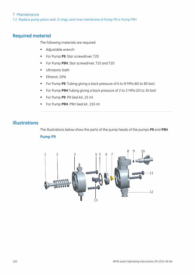
Required materialThe following materials are required:
• Adjustable wrench
• For Pump P9: Star screwdriver, T20
• For Pump P9H: Star screwdriver, T10 and T20
• Ultrasonic bath
• Ethanol, 20%
• For Pump P9: Tubing giving a back pressure of 6 to 8 MPa (60 to 80 bar).
• For Pump P9H:Tubing giving a back pressure of 2 to 3 MPa (20 to 30 bar)
• For Pump P9: P9 Seal kit, 25 ml
• For Pump P9H: P9H Seal kit, 150 ml
IllustrationsThe illustrations below show the parts of the pump heads of the pumps P9 and P9H.
Pump P9
1 2 3 4 5 6 7
12
98 10
11
13
150 ÄKTA avant Operating Instructions 29-1015-56 AA
7 Maintenance7.2 Replace pump piston seal, O-rings, and rinse membrane of Pump P9 or Pump P9H

Pump P9H
1 2 3 4 5 6 7
12
98 10
11
13
DescriptionPartDescriptionPart
Piston seal7Piston1
Outlet check valve8Return spring2
O-ring9Pump membrane housing3
Purge valve10Star screws4
Star screws11O-ring5
Inlet check valve12Support washer6
Star screws13
Disassemble the pump head
ActionStep
Make sure that no run is in progress on the instrument.1
Disconnect the tubing from the pump head, and disconnect the pump inlettubing.
2
ÄKTA avant Operating Instructions 29-1015-56 AA 151
7 Maintenance7.2 Replace pump piston seal, O-rings, and rinse membrane of Pump P9 or Pump P9H
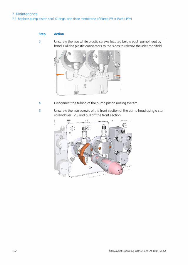
ActionStep
Unscrew the two white plastic screws located below each pump head byhand. Pull the plastic connectors to the sides to release the inlet manifold.
3
Disconnect the tubing of the pump piston rinsing system.4
Unscrew the two screws of the front section of the pump head using a starscrewdriver T20, and pull off the front section.
5
152 ÄKTA avant Operating Instructions 29-1015-56 AA
7 Maintenance7.2 Replace pump piston seal, O-rings, and rinse membrane of Pump P9 or Pump P9H
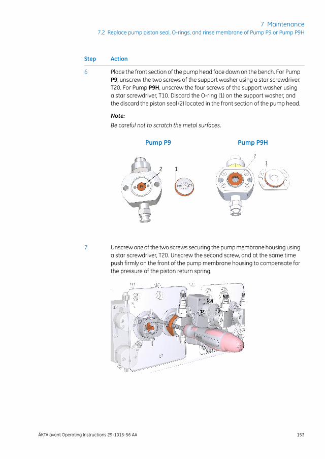
ActionStep
Place the front section of the pump head face down on the bench. For PumpP9, unscrew the two screws of the support washer using a star screwdriver,T20. For Pump P9H, unscrew the four screws of the support washer usinga star screwdriver, T10. Discard the O-ring (1) on the support washer, andthe discard the piston seal (2) located in the front section of the pump head.
Note:
Be careful not to scratch the metal surfaces.
6
Pump P9H
21
Pump P9
2 1
Unscrew one of the two screws securing the pump membrane housing usinga star screwdriver, T20. Unscrew the second screw, and at the same timepush firmly on the front of the pump membrane housing to compensate forthe pressure of the piston return spring.
7
ÄKTA avant Operating Instructions 29-1015-56 AA 153
7 Maintenance7.2 Replace pump piston seal, O-rings, and rinse membrane of Pump P9 or Pump P9H
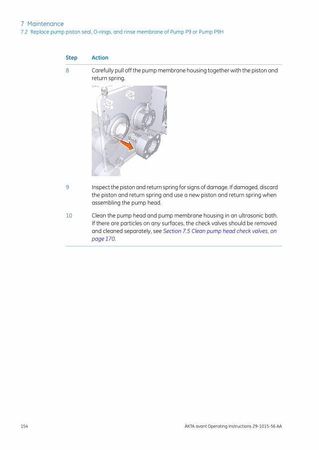
ActionStep
Carefully pull off the pump membrane housing together with the piston andreturn spring.
8
Inspect the piston and return spring for signs of damage. If damaged, discardthe piston and return spring and use a new piston and return spring whenassembling the pump head.
9
Clean the pump head and pump membrane housing in an ultrasonic bath.If there are particles on any surfaces, the check valves should be removedand cleaned separately, see Section 7.5 Clean pump head check valves, onpage 170.
10
154 ÄKTA avant Operating Instructions 29-1015-56 AA
7 Maintenance7.2 Replace pump piston seal, O-rings, and rinse membrane of Pump P9 or Pump P9H
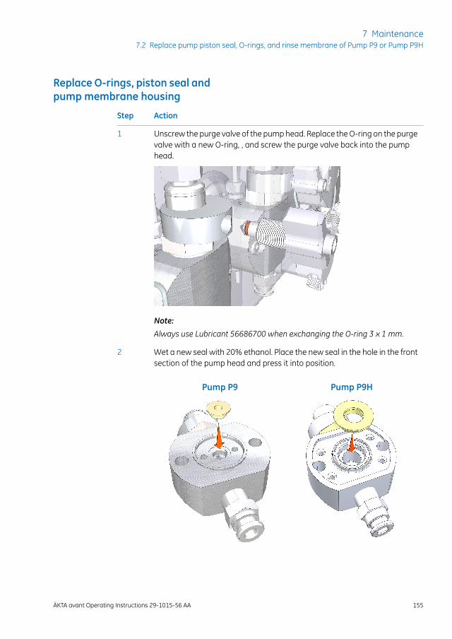
Replace O-rings, piston seal andpump membrane housing
ActionStep
Unscrew the purge valve of the pump head. Replace the O-ring on the purgevalve with a new O-ring, , and screw the purge valve back into the pumphead.
1
Note:
Always use Lubricant 56686700 when exchanging the O-ring 3 x 1 mm.
Wet a new seal with 20% ethanol. Place the new seal in the hole in the frontsection of the pump head and press it into position.
2
Pump P9HPump P9
ÄKTA avant Operating Instructions 29-1015-56 AA 155
7 Maintenance7.2 Replace pump piston seal, O-rings, and rinse membrane of Pump P9 or Pump P9H
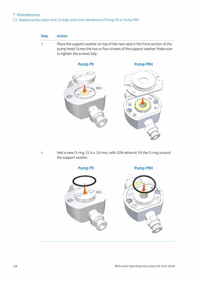
ActionStep
Place the support washer on top of the new seal in the front section of thepump head. Screw the two or four screws of the support washer. Make sureto tighten the screws fully.
3
Pump P9HPump P9
Wet a new O-ring, 21.4 x 1.6 mm, with 20% ethanol. Fit the O-ring aroundthe support washer.
4
Pump P9HPump P9
156 ÄKTA avant Operating Instructions 29-1015-56 AA
7 Maintenance7.2 Replace pump piston seal, O-rings, and rinse membrane of Pump P9 or Pump P9H
Assemble the pump headMake sure to assemble the pump head correctly. Refer to Illustrations, on page 150.
ActionStep
Insert the piston into the return spring. Insert piston and return spring intohole in the pump module.
Note:
Do no touch the ceramic or glass part of the pump piston.
1
Wet the membrane in the hole with 20% ethanol before mounting.2
Place the pump membrane housing onto the locating pins on the front ofthe pump module.
3
Screw one of the two screws securing the pump membrane housing usinga star screwdriver, T20. Push firmly on the front of the pump membranehousing to compensate for the pressure of the piston and then screw thesecond screw.
4
Make sure that the new seal is wetted with 20% ethanol and then tightenboth screws fully.
5
Reconnect the tubing of the pump piston rinsing system.6
Reconnect the inlet manifold.7
Reconnect the tubing to the pump head, and reconnect the pump inlettubing.
8
Break in the new pump pistonseal
Follow the instruction below to break in the new pump piston seal of Pump P9 or P9H.
ActionStep
Fill a buffer vessel with 20% ethanol in water. Immerse the inlet tubing, forexampleA1 for System Pump A, B1 for System Pump B, or S1 for the SamplePump in the buffer vessel. Place the buffer vessel on the buffer tray.
1
Prime the inlets and purge the pump, see Section 4.5.1 Prime buffer inletsand purge system pumps, on page 83.
2
ÄKTA avant Operating Instructions 29-1015-56 AA 157
7 Maintenance7.2 Replace pump piston seal, O-rings, and rinse membrane of Pump P9 or Pump P9H
ActionStep
• For Pump P9: Connect the reference capillary Ref 2 (or an equivalentcapillary that gives a backpressure of 6 to 8 MPa [60 to 80 bar]) to oneof the column positions of the column valve (e.g., ports 1A and 1B).
• For Pump P9H: Connect the reference capillary Ref 1 (or an equivalentcapillary that gives a backpressure of 2 to 3 MPa [20 to 30 bar] to oneof the column positions of the column valve (e.g., ports 1A and 1B).
3
Immerse the waste tubing in the buffer vessel to recirculate the liquid.4
• If breaking in a pump piston seal of a system pump, follow the instructionbelow:
In the Manual instructions dialog box:
- Select Flow path:Column valve, and select the position of the capil-lary connected to the column valve. Click Insert.
- Select Flow path:Inlet A (for System Pump A) or Flow path:Inlet B(for System Pump B) and select a Position. Click Insert.
- Select Pumps and Pressures:Gradient and set Target to 0% B (forSystem Pump A) or 100% B (for system pump B).
- For Pump P9: Select Pumps and Pressures:System flow and set theFlow rate to 5.0 to ml/min. Click Insert.
For Pump P9H: Select Pumps and Pressures:System flow and setthe Flow rate to 25.0 to ml/min. Click Insert.
- Click Execute.
Result: A system flow starts.
• If breaking in a pump piston seal of a sample pump, follow the instructionbelow:
In the Manual instructions dialog box:
- Select Flow path:Column valve, and select the position of the capil-lary connected to the column valve. Click Insert.
- Select Flow path:Sample inlet and select a Position. Click Insert.
- Select Flow path:Injection valve and click Direct inject on the Posi-tion menu. Click Insert.
- Select Pumps and Pressures:Sample flow and set the Flow rate to25.0 ml/min. Click Insert.
- Click Execute.
Result: A sample flow starts.
5
158 ÄKTA avant Operating Instructions 29-1015-56 AA
7 Maintenance7.2 Replace pump piston seal, O-rings, and rinse membrane of Pump P9 or Pump P9H
ActionStep
Run the flow for 2 hours.6
Discard the used buffer.7
ÄKTA avant Operating Instructions 29-1015-56 AA 159
7 Maintenance7.2 Replace pump piston seal, O-rings, and rinse membrane of Pump P9 or Pump P9H
7.3 Replace pump piston seal, O-ring, and rinse mem-brane of Pump P9-S
IntroductionFollow the instructions to replace the O-ring, piston seal, and rinse membrane of PumpP9-S.
Always replace the O-rings, piston seals, and rinse membranes of both pumpheads of a pump at the same time.
Note:
NOTICE
• Do not disassemble the pump head unless there is good reasonto believe that there is an internal leakage. A sign of leakageis increasing pump rinsing solution volume. Always make surethat sufficient spare components are available before attempt-ing to replace a spare part.
• Replacing spare parts. Read the instructions carefully. Forexample, some individual parts of the pump head can be as-sembled incorrectly. Check the orientation of each part beforecontinuing with the next instruction.
Maintenance intervalReplace the O-ring, piston seal, and rinse membrane of Pump P9-S if they are damaged.After replacement, perform a run to break in the new piston seal.
NOTICEAdvanced maintenance. Read the instruction carefully beforedisassembly of the pump head.
160 ÄKTA avant Operating Instructions 29-1015-56 AA
7 Maintenance7.3 Replace pump piston seal, O-ring, and rinse membrane of Pump P9-S

Required materialThe following material is required:
• Adjustable wrench
• Star screwdriver, T20
• Cross-headed screwdriver
• Hex wrench
• Ultrasonic bath
• Ethanol, 20%
• Reference capillary Ref 1
• P9-S Seal kit, 65 ml
IllustrationThe illustration below shows the parts of the pump heads of Pump P9-S.
1 2 3 4 5
10
87 9
6
DescriptionPartDescriptionPart
Piston seal6Piston1
Outlet check valve7Return spring2
O-ring8Drain plate3
Purge valve9Rinse membrane4
Inlet check valve10Rinse chamber5
ÄKTA avant Operating Instructions 29-1015-56 AA 161
7 Maintenance7.3 Replace pump piston seal, O-ring, and rinse membrane of Pump P9-S
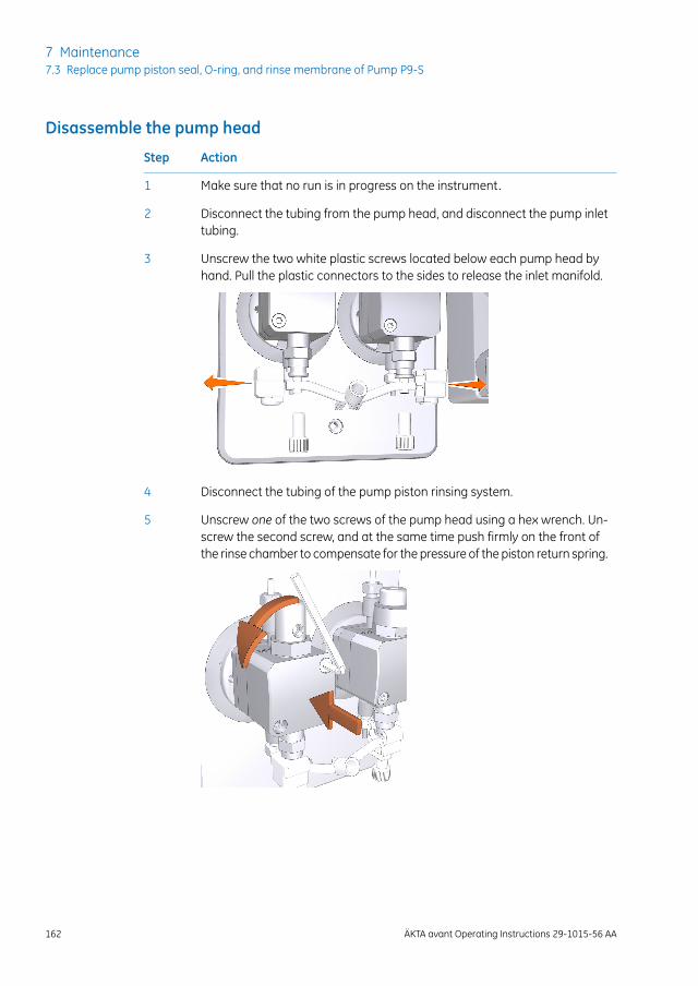
Disassemble the pump head
ActionStep
Make sure that no run is in progress on the instrument.1
Disconnect the tubing from the pump head, and disconnect the pump inlettubing.
2
Unscrew the two white plastic screws located below each pump head byhand. Pull the plastic connectors to the sides to release the inlet manifold.
3
Disconnect the tubing of the pump piston rinsing system.4
Unscrew one of the two screws of the pump head using a hex wrench. Un-screw the second screw, and at the same time push firmly on the front ofthe rinse chamber to compensate for the pressure of the piston return spring.
5
162 ÄKTA avant Operating Instructions 29-1015-56 AA
7 Maintenance7.3 Replace pump piston seal, O-ring, and rinse membrane of Pump P9-S
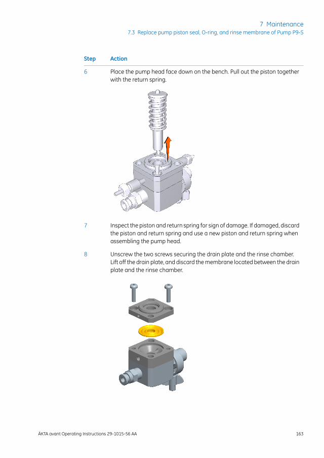
ActionStep
Place the pump head face down on the bench. Pull out the piston togetherwith the return spring.
6
Inspect the piston and return spring for sign of damage. If damaged, discardthe piston and return spring and use a new piston and return spring whenassembling the pump head.
7
Unscrew the two screws securing the drain plate and the rinse chamber.Lift off the drain plate, and discard the membrane located between the drainplate and the rinse chamber.
8
ÄKTA avant Operating Instructions 29-1015-56 AA 163
7 Maintenance7.3 Replace pump piston seal, O-ring, and rinse membrane of Pump P9-S
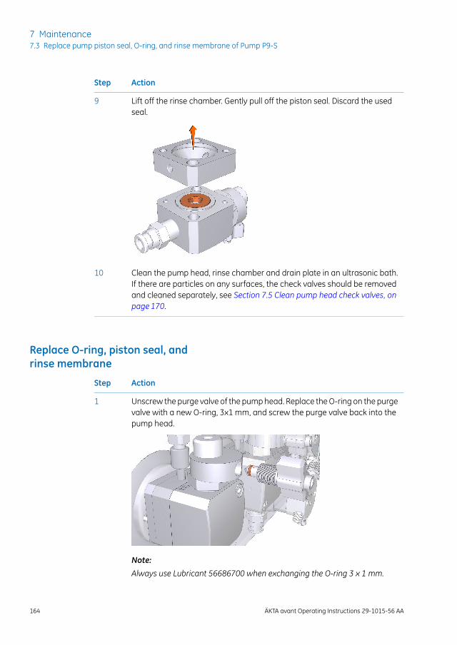
ActionStep
Lift off the rinse chamber. Gently pull off the piston seal. Discard the usedseal.
9
Clean the pump head, rinse chamber and drain plate in an ultrasonic bath.If there are particles on any surfaces, the check valves should be removedand cleaned separately, see Section 7.5 Clean pump head check valves, onpage 170.
10
Replace O-ring, piston seal, andrinse membrane
ActionStep
Unscrew the purge valve of the pump head. Replace the O-ring on the purgevalve with a new O-ring, 3x1 mm, and screw the purge valve back into thepump head.
1
Note:
Always use Lubricant 56686700 when exchanging the O-ring 3 x 1 mm.
164 ÄKTA avant Operating Instructions 29-1015-56 AA
7 Maintenance7.3 Replace pump piston seal, O-ring, and rinse membrane of Pump P9-S
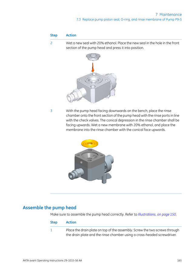
ActionStep
Wet a new seal with 20% ethanol. Place the new seal in the hole in the frontsection of the pump head and press it into position.
2
With the pump head facing downwards on the bench, place the rinsechamber onto the front section of the pump head with the rinse ports in linewith the check valves. The conical depression in the rinse chamber shall befacing upwards. Wet a new membrane with 20% ethanol, and place themembrane into the rinse chamber with the conical face upwards.
3
Assemble the pump headMake sure to assemble the pump head correctly. Refer to Illustrations, on page 150.
ActionStep
Place the drain plate on top of the assembly. Screw the two screws throughthe drain plate and the rinse chamber using a cross-headed screwdriver.
1
ÄKTA avant Operating Instructions 29-1015-56 AA 165
7 Maintenance7.3 Replace pump piston seal, O-ring, and rinse membrane of Pump P9-S
ActionStep
Wipe clean the piston and remove all finger prints. Wet the piston with 20%ethanol, and insert the piston into the return spring. With the pump headfacing downwards on the bench, insert the piston into the pump head bypushing it gently but firmly vertically downwards into the seal.
2
Place the complete pump head over the locating pins on the front panel ofthe sample pump module. Turn the pump head so that the text UP on thedrain plate is facing upwards. Push firmly on the front of the pump head,and at the same time screw one of the screws to fasten the pump headonto the front of the module using a hex wrench. Screw the second screwof the pump head. Make sure to tighten both screws fully.
3
Reconnect the tubing of the pump piston rinsing system.4
Reconnect the inlet manifold.5
Reconnect the tubing to the pump head, and reconnect the pump inlettubing.
6
Break in the new pump piston seal, see instruction below.7
Break in the new pump pistonseal
Follow the instruction to break in the new pump piston seal of Pump P9-S.
ActionStep
Fill a buffer vessel with 20% ethanol in water. Immerse a piece of sampleinlet tubing, for example S1, in the buffer vessel. Place the buffer vessel onthe buffer tray.
1
Prime the inlets and purge the pump, see Section 4.5.2 Prime sample inletsand purge Sample Pump, on page 90.
2
Connect the reference capillary Ref 1 (or an equivalent capillary that givesa backpressure of 2 to 3 MPa [20 to 30 bar]) to one of the column positionsof the column valve (e.g., ports 1A and 1B).
3
Immerse the waste tubing in the buffer vessel to recirculate the liquid.4
166 ÄKTA avant Operating Instructions 29-1015-56 AA
7 Maintenance7.3 Replace pump piston seal, O-ring, and rinse membrane of Pump P9-S
ActionStep
In the Manual instructions dialog:5
• Select Flowpath:Columnposition, and select thePositionof the capillaryconnected to the column valve. Click Insert.
• Select Flow path:Sample inlet and select a Position. Click Insert.
• Select Flow path:Injection valve and click Direct inject on the Positionmenu. Click Insert.
• Select Pumps:Sample flow and set the Flow rate to 25.0 ml/min. ClickInsert.
• Click Execute.
Result: A sample flow of 25.0 ml/min starts.
Run the flow for 2 hours.6
Discard the used buffer.7
ÄKTA avant Operating Instructions 29-1015-56 AA 167
7 Maintenance7.3 Replace pump piston seal, O-ring, and rinse membrane of Pump P9-S
7.4 Replace pump pistons
IntroductionFollow the instructions to replace the pump pistons of the pumps P9, P9H and P9-S.
Always replace the O-rings, piston seals, and rinse membranes of both pumpheads of a pump at the same time.
Note:
NOTICE
• Do not disassemble the pump head unless there is good reasonto believe that there is an internal leakage. A sign of leakageis increasing pump rinsing solution volume. Always make surethat sufficient spare components are available before attempt-ing to replace a spare part.
• Replacing spare parts. Read the instructions carefully. Forexample, some individual parts of the pump head can be as-sembled incorrectly. Check the orientation of each part beforecontinuing with the next instruction.
Maintenance intervalReplace the pump pistons if they are damaged.
Required materialThe following materials are required:
• Adjustable wrench
• Star screwdriver, T20
• Piston kit
168 ÄKTA avant Operating Instructions 29-1015-56 AA
7 Maintenance7.4 Replace pump pistons
Replace pump pistons of PumpP9 and P9H
If a damaged piston has been in operation, the piston seal will be destroyed and shouldalso be replaced. To replace the piston and the seal of a system pump, see Section 7.2Replace pump piston seal, O-rings, and rinse membrane of Pump P9 or Pump P9H, onpage149. Section 7.2 Replace pumppiston seal, O-rings, and rinsemembrane of PumpP9or Pump P9H, on page 149.
Replace pump pistons of PumpP9-S
If a damaged piston has been in operation, the piston seal will be destroyed and shouldalso be replaced. To replace the piston and the seal of Pump P9-S, see Section 7.3 Replacepump piston seal, O-ring, and rinse membrane of Pump P9-S, on page 160.
ÄKTA avant Operating Instructions 29-1015-56 AA 169
7 Maintenance7.4 Replace pump pistons
7.5 Clean pump head check valves
IntroductionClean the check valves when required, for example if particles like dust or salt crystalsin the check valve cause irregular or low flow. The cleaning procedure is the same forthe system pumps and the sample pump.
Required materialThe following materials are required:
• Adjustable wrench
• 100% Methanol
• Distilled water
• Ultrasonic bath
InstructionFollow the instructions to remove and clean the pump head check valves.
ActionStep
Before taking the check valve apart, always try to clean the check valves bypriming the pump heads first with distilled water, then with 100% Methanoland then with distilled water again.
1
Switch off the instrument.2
Disconnect the tubing from the pump head and disconnect the pump inlettubing. Disconnect the tubing of the pump rinsing system.
3
170 ÄKTA avant Operating Instructions 29-1015-56 AA
7 Maintenance7.5 Clean pump head check valves
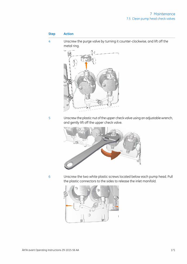
ActionStep
Unscrew the purge valve by turning it counter-clockwise, and lift off themetal ring.
4
Unscrew the plastic nut of the upper check valve using an adjustable wrench,and gently lift off the upper check valve.
5
Unscrew the two white plastic screws located below each pump head. Pullthe plastic connectors to the sides to release the inlet manifold.
6
ÄKTA avant Operating Instructions 29-1015-56 AA 171
7 Maintenance7.5 Clean pump head check valves
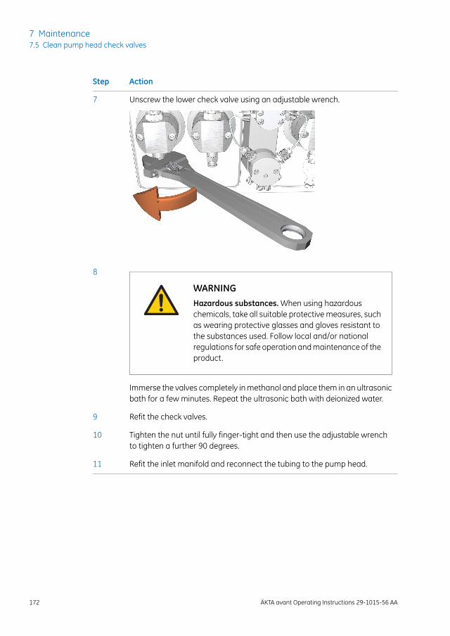
ActionStep
Unscrew the lower check valve using an adjustable wrench.7
WARNINGHazardous substances. When using hazardouschemicals, take all suitable protective measures, suchas wearing protective glasses and gloves resistant tothe substances used. Follow local and/or nationalregulations for safe operation and maintenance of theproduct.
8
Immerse the valves completely in methanol and place them in an ultrasonicbath for a few minutes. Repeat the ultrasonic bath with deionized water.
Refit the check valves.9
Tighten the nut until fully finger-tight and then use the adjustable wrenchto tighten a further 90 degrees.
10
Refit the inlet manifold and reconnect the tubing to the pump head.11
172 ÄKTA avant Operating Instructions 29-1015-56 AA
7 Maintenance7.5 Clean pump head check valves
8 Reference Information
About this chapterThis chapter lists the technical specifications of the ÄKTA avant instrument. The chapteralso includes a chemical resistance guide. See alsoÄKTAavant 25 Product Documentationand ÄKTA avant 150 Product Documentation for detailed technical specifications.
In this chapterThis chapter contains the following sections:
See pageSection
1748.1 System specifications
1768.2 Chemical resistance guide
1818.3 Check and change the Node ID of a module
ÄKTA avant Operating Instructions 29-1015-56 AA 173
8 Reference Information
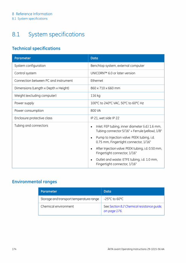
8.1 System specifications
Technical specifications
DataParameter
Benchtop system, external computerSystem configuration
UNICORN™ 6.0 or later versionControl system
EthernetConnection between PC and instrument
860 x 710 x 660 mmDimensions (Length x Depth x Height)
116 kgWeight (excluding computer)
100°C to 240°C VAC, 50°C to 60°C HzPower supply
800 VAPower consumption
IP 21, wet side IP 22Enclosure protective class
• Inlet: FEP tubing, inner diameter (i.d.) 1.6 mm,Tubing connector 5/16" + Ferrule (yellow), 1/8"
• Pump to Injection valve: PEEK tubing, i.d.0.75 mm, Fingertight connector, 1/16"
• After Injection valve: PEEK tubing, i.d. 0.50 mm,Fingertight connector, 1/16"
• Outlet and waste: ETFE tubing, i.d. 1.0 mm,Fingertight connector, 1/16"
Tubing and connectors
Environmental ranges
DataParameter
-25°C to 60°CStorage and transport temperature range
See Section 8.2 Chemical resistance guide,on page 176.
Chemical environment
174 ÄKTA avant Operating Instructions 29-1015-56 AA
8 Reference Information8.1 System specifications
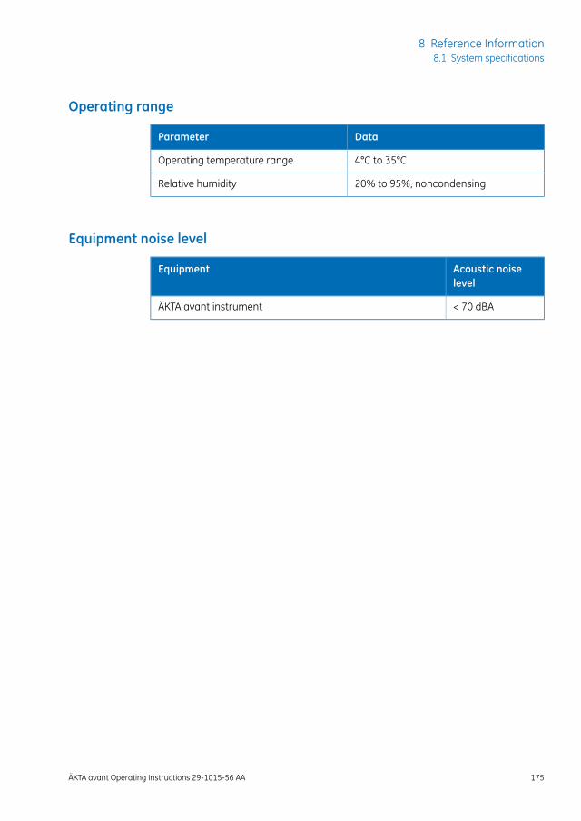
Operating range
DataParameter
4°C to 35°COperating temperature range
20% to 95%, noncondensingRelative humidity
Equipment noise level
Acoustic noiselevel
Equipment
< 70 dBAÄKTA avant instrument
ÄKTA avant Operating Instructions 29-1015-56 AA 175
8 Reference Information8.1 System specifications
8.2 Chemical resistance guide
IntroductionThis section specifies the chemical resistance of the ÄKTA avant instrument to some ofthe most commonly used chemicals in liquid chromatography.
BiocompatibilityThe ÄKTA avant instrument is designed for maximum biocompatibility, with biochemicallyinert flow paths constructed mainly from titanium, PEEK and highly resistant fluoropoly-mers and fluoroelastomers. Titanium is used as far as possible to minimize contributionof potentially deactivating metal ions such as iron, nickel and chromium. There is nostandard stainless steel in the flow path. Plastics and rubber materials are selected toavoid leakage of monomers, plasticizers or other additives.
Cleaning chemicalsStrong cleaning works well with 2 M sodium hydroxide, 70% acetic acid or the alcoholsmethanol, ethanol and isopropyl alcohol. Complete system cleaning using 1 M hydrochlo-ric acid should be avoided in order to not damage the pressure sensors. If you arecleaning separation media using 1 M hydrochloric acid, use loop injections of the acidand make sure that the column is not mounted on the Column Valve V9-C. The ColumnValve V9-C contains a pressure sensor which can be damaged by 1 M hydrochloric acid.
Long time use of 0.2 M HCl connected to the Quaternary Valve Q9 as part of a BufferProrecipe is acceptable. The solution becomes diluted further down in the system.
If sodium hypochlorite is used as sanitizing agent instead of 2 M sodium hydroxide, usea concentration up to 10%.
Organic solventsReversed phase chromatography of proteins works well with 100% acetonitrile and ad-ditives trifluoroacetic acid (TFA) up to 0.2% or formic acid up to 5%.
Strong organic solvents like ethyl acetate, 100% acetone or chlorinated organic solventsshould be avoided. These might cause swelling of plastic material and reduce the pressuretolerance of PEEK tubing. For this reason, flash chromatography and straight (“normal”)phase chromatography is generally not recommended on the system
176 ÄKTA avant Operating Instructions 29-1015-56 AA
8 Reference Information8.2 Chemical resistance guide
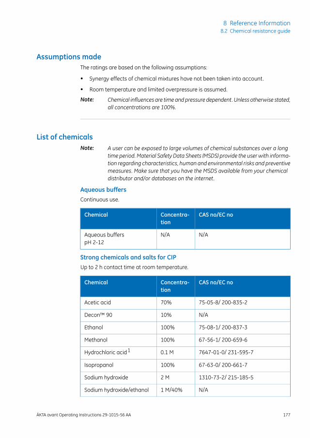
Assumptions madeThe ratings are based on the following assumptions:
• Synergy effects of chemical mixtures have not been taken into account.
• Room temperature and limited overpressure is assumed.
Chemical influences are timeandpressure dependent. Unless otherwise stated,all concentrations are 100%.
Note:
List of chemicalsA user can be exposed to large volumes of chemical substances over a longtime period. Material Safety Data Sheets (MSDS) provide the userwith informa-tion regarding characteristics, humanand environmental risks and preventivemeasures. Make sure that you have the MSDS available from your chemicaldistributor and/or databases on the internet.
Note:
Aqueous buffersContinuous use.
CAS no/EC noConcentra-tion
Chemical
N/AN/AAqueous bufferspH 2-12
Strong chemicals and salts for CIPUp to 2 h contact time at room temperature.
CAS no/EC noConcentra-tion
Chemical
75-05-8/ 200-835-270%Acetic acid
N/A10%Decon™ 90
75-08-1/ 200-837-3100%Ethanol
67-56-1/ 200-659-6100%Methanol
7647-01-0/ 231-595-70.1 MHydrochloric acid1
67-63-0/ 200-661-7100%Isopropanol
1310-73-2/ 215-185-52 MSodium hydroxide
N/A1 M/40%Sodium hydroxide/ethanol
ÄKTA avant Operating Instructions 29-1015-56 AA 177
8 Reference Information8.2 Chemical resistance guide
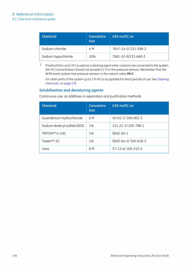
CAS no/EC noConcentra-tion
Chemical
7647-14-5/ 231-598-34 MSodium chloride
7681-52-9/231-668-310%Sodium hypochlorite
1 If hydrochloric acid, HCl, is used as a cleaning agent when columns are connected to the system,the HCl concentration should not exceed 0.1 M in the pressure sensors. Remember that theÄKTA avant system has pressure sensors in the column valve V9-C.
For other parts of the system up to 1 M HCl is acceptable for short periods of use. See Cleaningchemicals, on page 176
Solubilization and denaturing agentsContinuous use, as additives in separation and purification methods
CAS no/EC noConcentra-tion
Chemical
50-01-1/ 200-002-36 MGuanidinium hydrochloride
151-21-3/ 205-788-11%Sodium dodecyl sulfate (SDS)
9002-93-11%TRITON™ X-100
9005-64-5/ 500-018-31%Tween™ 20
57-13-6/ 200-315-58 MUrea
178 ÄKTA avant Operating Instructions 29-1015-56 AA
8 Reference Information8.2 Chemical resistance guide
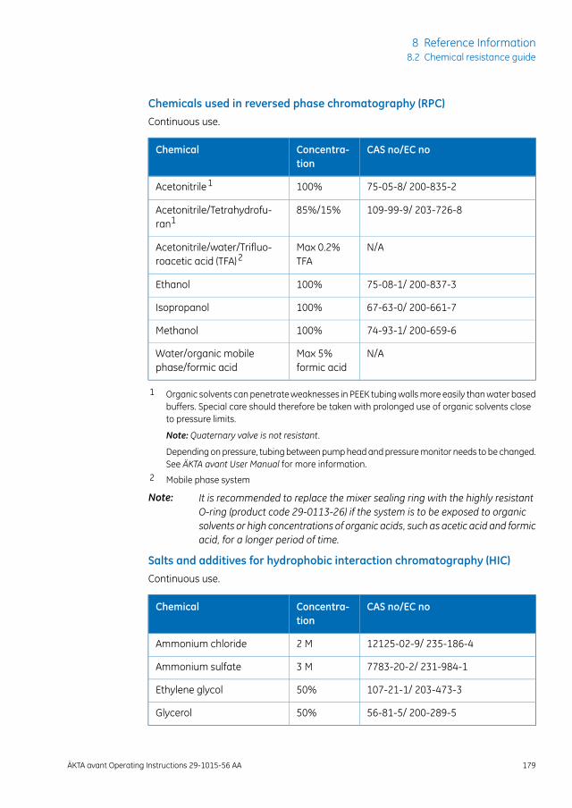
Chemicals used in reversed phase chromatography (RPC)Continuous use.
CAS no/EC noConcentra-tion
Chemical
75-05-8/ 200-835-2100%Acetonitrile1
109-99-9/ 203-726-885%/15%Acetonitrile/Tetrahydrofu-ran1
N/AMax 0.2%TFA
Acetonitrile/water/Trifluo-roacetic acid (TFA)2
75-08-1/ 200-837-3100%Ethanol
67-63-0/ 200-661-7100%Isopropanol
74-93-1/ 200-659-6100%Methanol
N/AMax 5%formic acid
Water/organic mobilephase/formic acid
1 Organic solvents can penetrate weaknesses in PEEK tubing walls more easily than water basedbuffers. Special care should therefore be taken with prolonged use of organic solvents closeto pressure limits.
Note: Quaternary valve is not resistant.
Depending on pressure, tubing between pump head and pressure monitor needs to be changed.See ÄKTA avant User Manual for more information.
2 Mobile phase system
It is recommended to replace the mixer sealing ring with the highly resistantO-ring (product code 29-0113-26) if the system is to be exposed to organicsolvents or high concentrations of organic acids, such as acetic acid and formicacid, for a longer period of time.
Note:
Salts and additives for hydrophobic interaction chromatography (HIC)Continuous use.
CAS no/EC noConcentra-tion
Chemical
12125-02-9/ 235-186-42 MAmmonium chloride
7783-20-2/ 231-984-13 MAmmonium sulfate
107-21-1/ 203-473-350%Ethylene glycol
56-81-5/ 200-289-550%Glycerol
ÄKTA avant Operating Instructions 29-1015-56 AA 179
8 Reference Information8.2 Chemical resistance guide
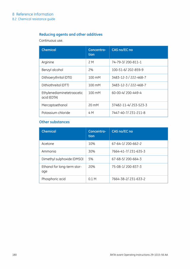
Reducing agents and other additivesContinuous use.
CAS no/EC noConcentra-tion
Chemical
74-79-3/ 200-811-12 MArginine
100-51-6/ 202-859-92%Benzyl alcohol
3483-12-3 / 222-468-7100 mMDithioerythritol (DTE)
3483-12-3 / 222-468-7100 mMDithiothreitol (DTT)
60-00-4/ 200-449-4100 mMEthylenediaminetetraaceticacid (EDTA)
37482-11-4/ 253-523-320 mMMercaptoethanol
7447-40-7/ 231-211-84 MPotassium chloride
Other substances
CAS no/EC noConcentra-tion
Chemical
67-64-1/ 200-662-210%Acetone
7664-41-7/ 231-635-330%Ammonia
67-68-5/ 200-664-35%Dimethyl sulphoxide (DMSO)
75-08-1/ 200-837-320%Ethanol for long-term stor-age
7664-38-2/ 231-633-20.1 MPhosphoric acid
180 ÄKTA avant Operating Instructions 29-1015-56 AA
8 Reference Information8.2 Chemical resistance guide

8.3 Check and change the Node ID of a module
IntroductionNode ID is a unit number designation that is used by the instrument to distinguish be-tween several units of the same type. All standard valves and available optional modulesare pre-configured to the default function. However, the function of a valve or modulecan be changed by changing the Node ID. Also, in a troubleshooting situation it may beuseful to check a valve's or module's Node ID.
The function of a valve or module is defined by its Node ID, not by its physicalposition.
Note:
Node ID for standard modulesThe following table lists the Node ID for the standard modules.
Node IDLabelModule
0P9 A or P9H ASystem Pump A
1P9 B or P9H BSystem Pump B
2P9-S or P9H SSample Pump
0R9Pressure Monitor, system pressure
1R9Pressure Monitor, sample pressure
0M9Mixer
4V9-Inj or V9H-InjInjection Valve
0Q9Quaternary Valve
0V9-IA or V9H-IAInlet Valve A
1V9-IB or V9H-IBInlet Valve B
2V9-IS or V9H-ISSample Inlet Valve
5V9-C or V9H-CColumn Valve
2N/APrecolumn pressure monitor in ColumnValve
3N/APost-column pressure monitor in ColumnValve
ÄKTA avant Operating Instructions 29-1015-56 AA 181
8 Reference Information8.3 Check and change the Node ID of a module

Node IDLabelModule
11V9-pH or V9H-pHpH Valve
0H9pH Monitor
Note:
The pHmonitor is included in the pH valvemodule box.
8V9-O or V9H-OOutlet Valve
0U9-MUV Monitor
0U9-DUV detector
0C9Conductivity Monitor
Not settable by theuser.
N/ABuilt-in fraction collector
Node ID for optional modulesThe following table lists the Node ID for the optional modules.
Node IDLabelModule
12V9-A2 or V9H-A2Second Inlet Valve A
13V9-B2 or V9H-B2Second Inlet Valve B
15V9-IX or V9H-IXExtra Inlet Valve X1
16V9-IX or V9H-IXExtra Inlet Valve X2
14V9-S2 or V9H-S2Second Sample Inlet Valve
20V9-V or V9H-VVersatile Valve
21V9-V or V9H-VSecond Versatile Valve
23V9-V or V9H-VThird Versatile Valve
24V9-V or V9H-VTertiary Versatile Valve
17V9-L or V9H-LLoop Valve
6V9-C2 or V9H-C2Second Column Valve
4N/AUnused precolumn pressure monitor insecond Column Valve
182 ÄKTA avant Operating Instructions 29-1015-56 AA
8 Reference Information8.3 Check and change the Node ID of a module
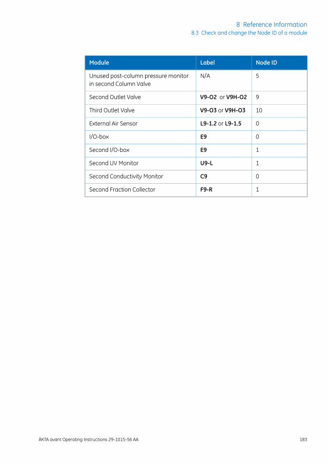
Node IDLabelModule
5N/AUnused post-column pressure monitorin second Column Valve
9V9-O2 or V9H-O2Second Outlet Valve
10V9-O3 or V9H-O3Third Outlet Valve
0L9-1.2 or L9-1.5External Air Sensor
0E9I/O-box
1E9Second I/O-box
1U9-LSecond UV Monitor
0C9Second Conductivity Monitor
1F9-RSecond Fraction Collector
ÄKTA avant Operating Instructions 29-1015-56 AA 183
8 Reference Information8.3 Check and change the Node ID of a module
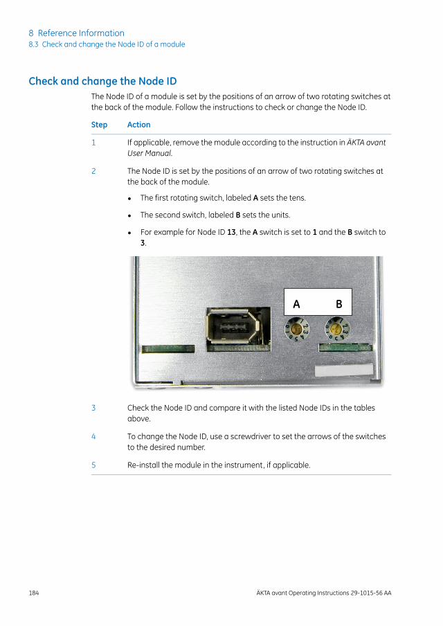
Check and change the Node IDThe Node ID of a module is set by the positions of an arrow of two rotating switches atthe back of the module. Follow the instructions to check or change the Node ID.
ActionStep
If applicable, remove the module according to the instruction in ÄKTA avantUser Manual.
1
The Node ID is set by the positions of an arrow of two rotating switches atthe back of the module.
2
• The first rotating switch, labeled A sets the tens.
• The second switch, labeled B sets the units.
• For example for Node ID 13, the A switch is set to 1 and the B switch to3.
A B
Check the Node ID and compare it with the listed Node IDs in the tablesabove.
3
To change the Node ID, use a screwdriver to set the arrows of the switchesto the desired number.
4
Re-install the module in the instrument, if applicable.5
184 ÄKTA avant Operating Instructions 29-1015-56 AA
8 Reference Information8.3 Check and change the Node ID of a module
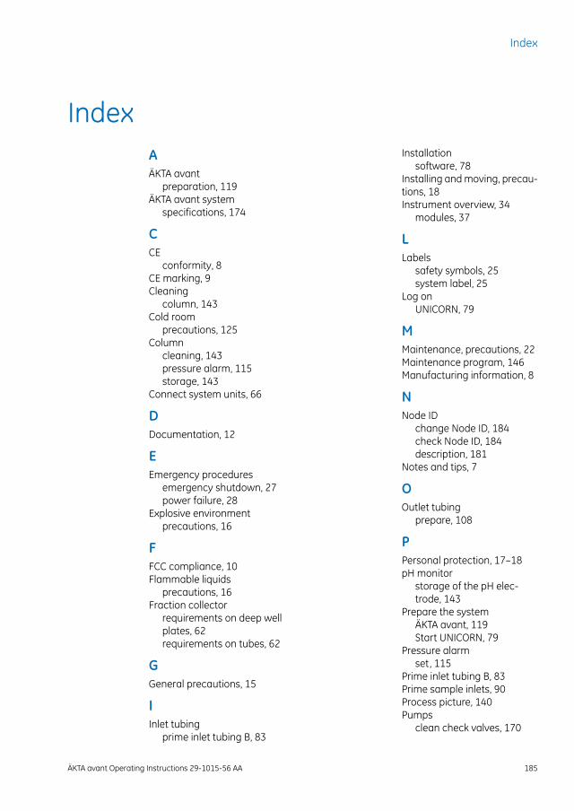
IndexAÄKTA avant
preparation, 119ÄKTA avant system
specifications, 174
CCE
conformity, 8CE marking, 9Cleaning
column, 143Cold room
precautions, 125Column
cleaning, 143pressure alarm, 115storage, 143
Connect system units, 66
DDocumentation, 12
EEmergency procedures
emergency shutdown, 27power failure, 28
Explosive environmentprecautions, 16
FFCC compliance, 10Flammable liquids
precautions, 16Fraction collector
requirements on deep wellplates, 62requirements on tubes, 62
GGeneral precautions, 15
IInlet tubing
prime inlet tubing B, 83
Installationsoftware, 78
Installing and moving, precau-tions, 18Instrument overview, 34
modules, 37
LLabels
safety symbols, 25system label, 25
Log onUNICORN, 79
MMaintenance, precautions, 22Maintenance program, 146Manufacturing information, 8
NNode ID
change Node ID, 184check Node ID, 184description, 181
Notes and tips, 7
OOutlet tubing
prepare, 108
PPersonal protection, 17–18pH monitor
storage of the pH elec-trode, 143
Prepare the systemÄKTA avant, 119Start UNICORN, 79
Pressure alarmset, 115
Prime inlet tubing B, 83Prime sample inlets, 90Process picture, 140Pumps
clean check valves, 170
ÄKTA avant Operating Instructions 29-1015-56 AA 185
Index
purge system pumps, 83replace pump pistons, 168replace pump piston sealsof Pump P9 or P9H, 149replace pump piston sealsof Pump P9-S, 160
Purpose of this manual, 5
RRecycling
disposal, 30Recycling procedures, 30Reference information
chemical resistanceguide, 176system specifications, 174
Regulatory compliance, 11Regulatory information, 8
international standards, 9Room requirements
introduction, 52Run
after run procedures, 142monitor a run, 139start, 133
SSafety
notices, 7Safety precautions, 15
emergency procedures, 27general precautions, 15installing and moving theinstrument, 18, 50labels, 24
system operation, 54Software overview, 44
software modules, 45Storage
column, 143pH electrode, 143system, 143
System Control moduledescription, 46icons, 47process picture, 140
System label, 25System preparation
before preparation, 102System recommendations
computer specifications, 59System storage, 143
TTechnical specifications
system specifications, 174Typographical conventions, 5
UUNICORN, 44
connect to system, 81Log on, 79Start, 79System Control module, 46
User information, important, 6
WWaste tubing
prepare, 71, 108
186 ÄKTA avant Operating Instructions 29-1015-56 AA
Index
GE and GE monogram are trademarks of General Electric Company.
ÄKTA is a trademark of General Electric Company or one of its subsidiaries.
BD is a trademark of Becton, Dickinson and Company
Decon is a trademark of Decon Laboratories Limited.
Eppendorf is a trademark of Eppendorf AG.
Microsoft and Windows are registered trademarks of Microsoft Corporation.
NUNC and Thermo Scientific are trademarks of Thermo Fisher Scientific or itssubsidiaries.
SARSTEDT is a trademark of SARSTEDT AG & CO.
Seahorse Bioscience is a trademark of Seahorse Bioscience Inc.
Triton is a trademark of Union Carbide Chemicals and Plastic Company Inc.
Tween is a trademark of Uniqema Americas LLC.
VWR is a trademark of VWR International, LLC.
All other third party trademarks are the property of their respective owner.
Any use of UNICORN is subject to GE Healthcare Standard Software End-UserLicense Agreement for Life Sciences Software Products. A copy of this StandardSoftware End-User License Agreement is available on request.
© 2015 General Electric Company – All rights reserved.First published Mar. 2015
All goods and services are sold subject to the terms and conditions of sale ofthe company within GE Healthcare which supplies them. A copy of these termsand conditions is available on request. Contact your local GE Healthcare repre-sentative for the most current information.
GE Healthcare Europe GmbHMunzinger Strasse 5, D-79111 Freiburg, Germany
GE Healthcare UK LimitedAmersham Place, Little Chalfont, Buckinghamshire, HP7 9NA, UK
GE Healthcare Bio-Sciences Corp.800 Centennial Avenue, P.O. Box 1327, Piscataway, NJ 08855-1327, USA
GE Healthcare Japan CorporationSanken Bldg. 3-25-1, Hyakunincho Shinjuku-ku, Tokyo 169-0073, Japan
For local office contact information, visitwww.gelifesciences.com/contact
GE Healthcare Bio-Sciences ABBjörkgatan 30751 84 UppsalaSweden
www.gelifesciences.com/avant
29-1015-56 AA 03/2015 a24