Embed Size (px)
Citation preview
ksjp
, 7/0
1
MEMS Design & Fab
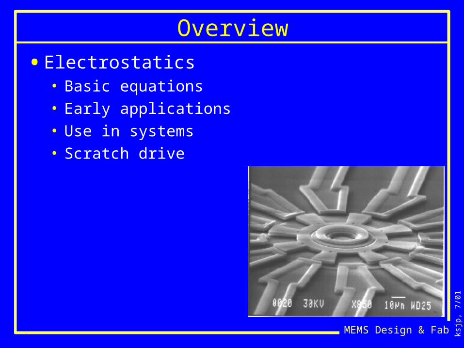
Overview
• Electrostatics• Basic equations• Early applications• Use in systems• Scratch drive
ksjp
, 7/0
1
MEMS Design & Fab
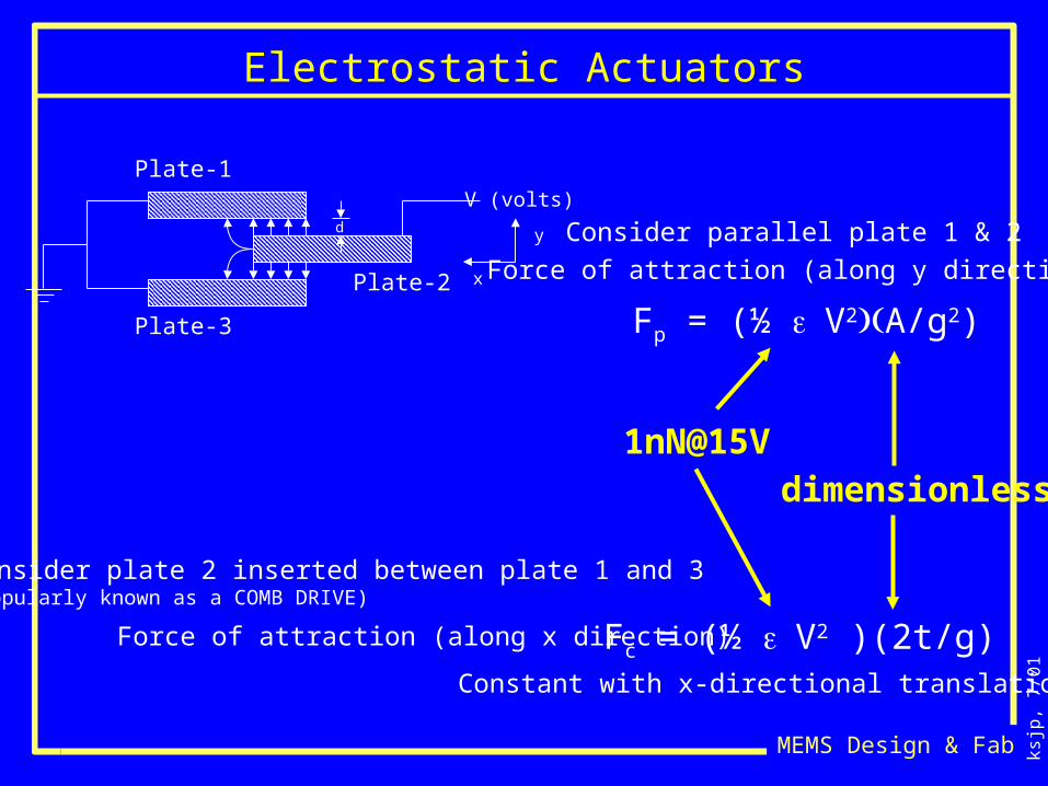
Electrostatic Actuators
Plate-1
Plate-2
Plate-3
V (volts)
x
yd Consider parallel plate 1 & 2
Force of attraction (along y direction)
Fp = (½ V2A/g2)
1nN@15Vdimensionless
Consider plate 2 inserted between plate 1 and 3(Popularly known as a COMB DRIVE)
Fc = (½ V2 )(2t/g)Force of attraction (along x direction)
Constant with x-directional translation
ksjp
, 7/0
1
MEMS Design & Fab
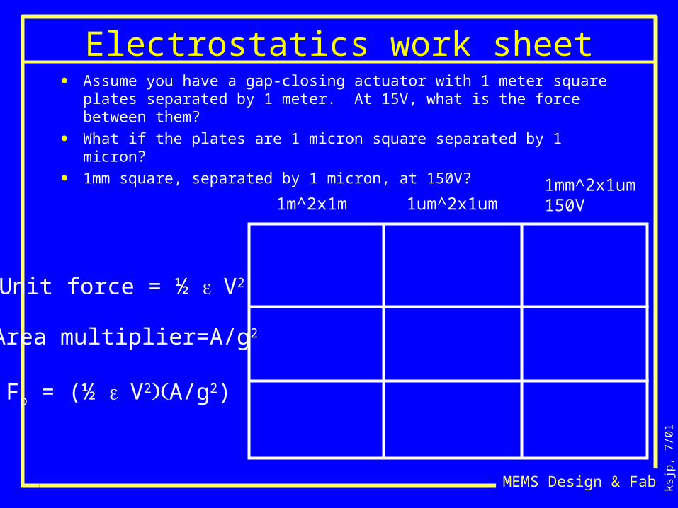
Electrostatics work sheet• Assume you have a gap-closing actuator with 1 meter square plates separated
by 1 meter. At 15V, what is the force between them?
• What if the plates are 1 micron square separated by 1 micron?
• 1mm square, separated by 1 micron, at 150V?
Unit force = ½ V2
Area multiplier=A/g2
Fp = (½ V2A/g2)
1m^2x1m 1um^2x1um1mm^2x1um150V
ksjp
, 7/0
1
MEMS Design & Fab
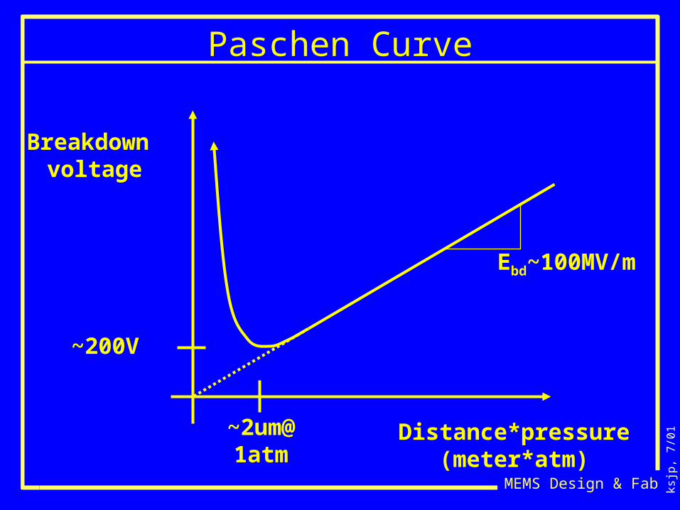
Paschen Curve
Distance*pressure(meter*atm)
Breakdown voltage
Ebd~100MV/m
~200V
~2um@1atm
ksjp
, 7/0
1
MEMS Design & Fab
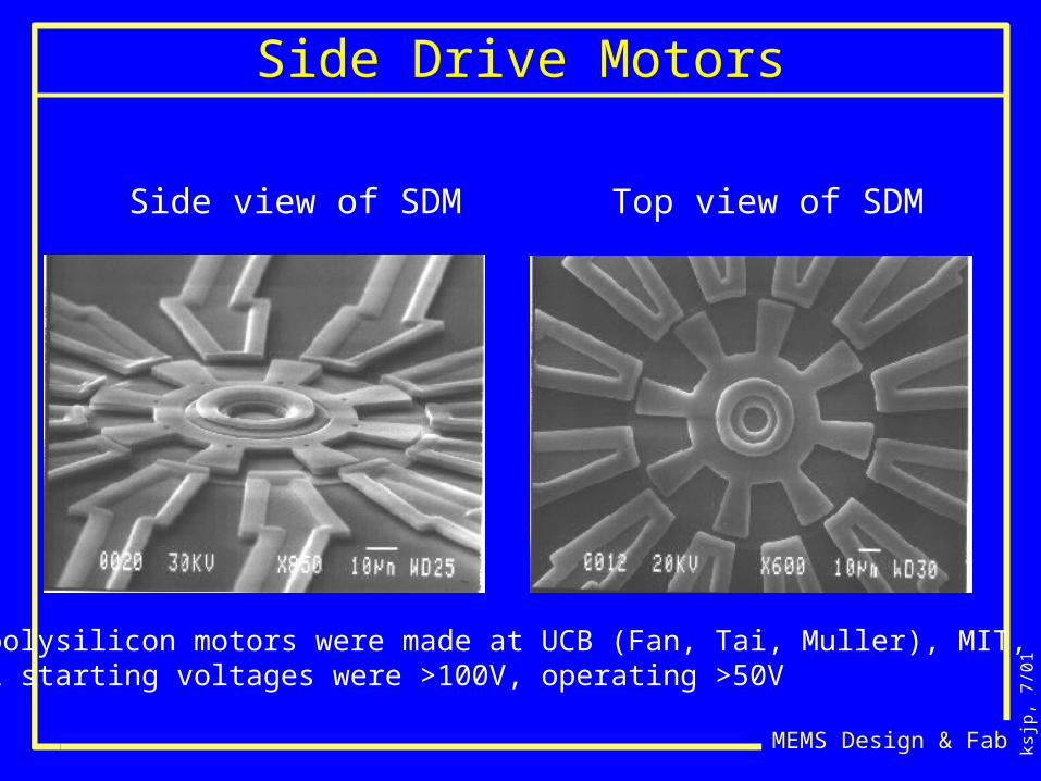
Side view of SDM Top view of SDM
First polysilicon motors were made at UCB (Fan, Tai, Muller), MIT, ATTTypical starting voltages were >100V, operating >50V
Side Drive Motors
ksjp
, 7/0
1
MEMS Design & Fab
High-Aspect-Ratio Rotary Polygon Micromotor Scanners
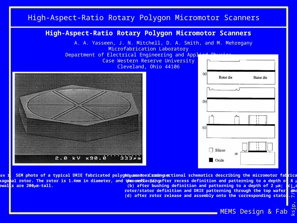
High-Aspect-Ratio Rotary Polygon Micromotor Scanners
A. A. Yasseen, J. N. Mitchell, D. A. Smith, and M. MehreganyMicrofabrication Laboratory
Department of Electrical Engineering and Applied PhysicsCase Western Reserve University
Cleveland, Ohio 44106
Figure 1. SEM photo of a typical DRIE fabricated polygon scanner using a hexagonal rotor. The rotor is 1.4mm in diameter, and the reflectingsidewalls are 200m-tall.
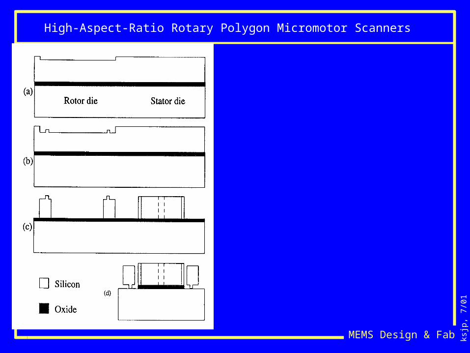
Figure 3. Cross-sectional schematics describing the micromotor fabrication process: (a) after recess definition and patterning to a depth of 8 m; (b) after bushing definition and patterning to a depth of 2 m; (c) after rotor/stator definition and DRIE patterning through the top wafer; and (d) after rotor release and assembly onto the corresponding stator.
ksjp
, 7/0
1
MEMS Design & Fab
High-Aspect-Ratio Rotary Polygon Micromotor Scanners
ksjp
, 7/0
1
MEMS Design & Fab
A Rotary Electrostatic Micromotor 18 Optical Switch
Micro Electro Mechanical SystemsJan., 1998 Heidelberg, Germany
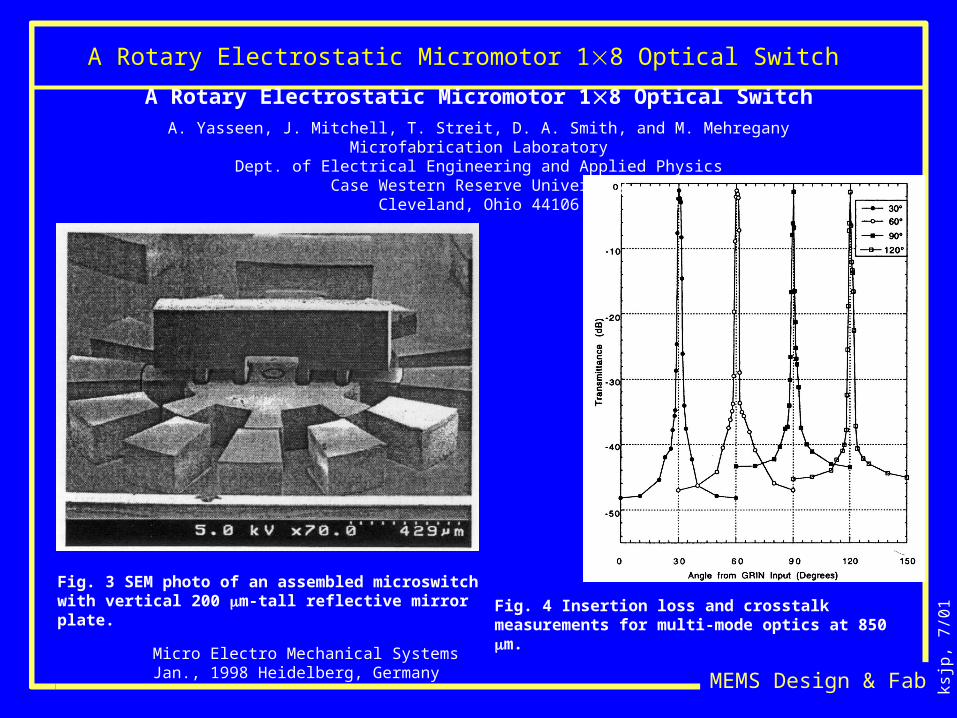
A Rotary Electrostatic Micromotor 18 Optical Switch
A. Yasseen, J. Mitchell, T. Streit, D. A. Smith, and M. MehreganyMicrofabrication Laboratory
Dept. of Electrical Engineering and Applied PhysicsCase Western Reserve University
Cleveland, Ohio 44106
Fig. 3 SEM photo of an assembled microswitch with vertical 200 m-tall reflective mirror plate. Fig. 4 Insertion loss and crosstalk measurements for multi-
mode optics at 850 m.
ksjp
, 7/0
1
MEMS Design & Fab
Fiber Attenuator
Solid-State Sensor and Actuator WorkshopHilton Head 1998
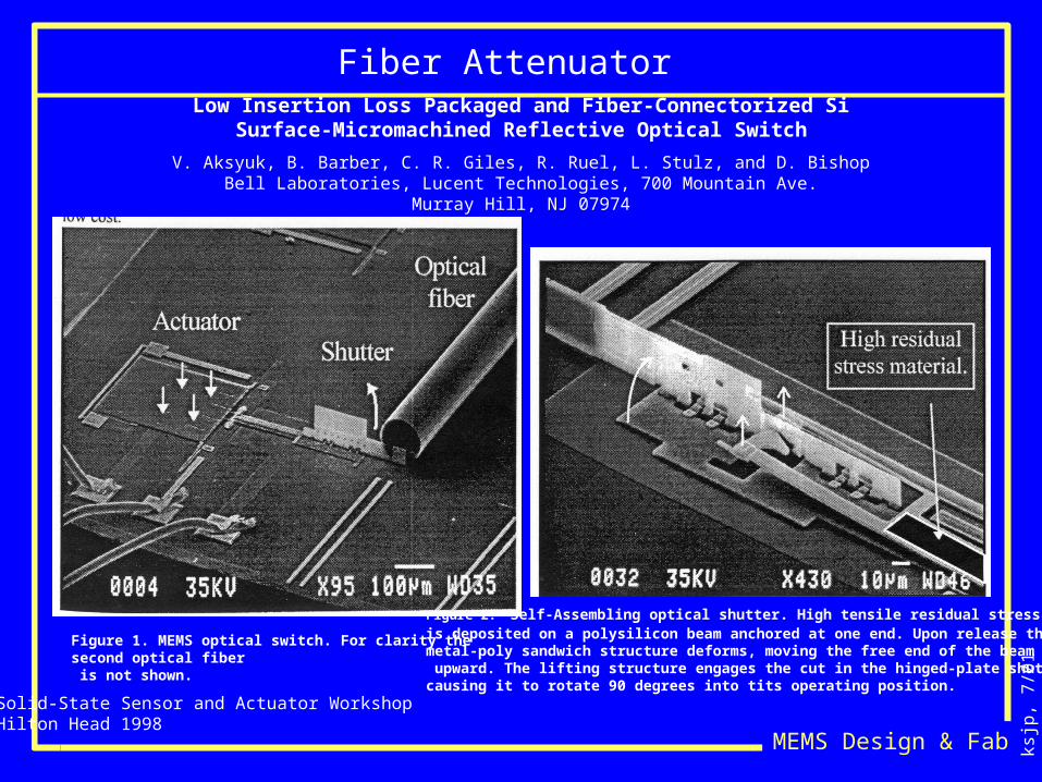
Low Insertion Loss Packaged and Fiber-Connectorized SiSurface-Micromachined Reflective Optical Switch
V. Aksyuk, B. Barber, C. R. Giles, R. Ruel, L. Stulz, and D. BishopBell Laboratories, Lucent Technologies, 700 Mountain Ave.
Murray Hill, NJ 07974
Figure 1. MEMS optical switch. For clarity the second optical fiber is not shown.
Figure 2. Self-Assembling optical shutter. High tensile residual stress metal is deposited on a polysilicon beam anchored at one end. Upon release the metal-poly sandwich structure deforms, moving the free end of the beam upward. The lifting structure engages the cut in the hinged-plate shutter causing it to rotate 90 degrees into tits operating position.
ksjp
, 7/0
1
MEMS Design & Fab
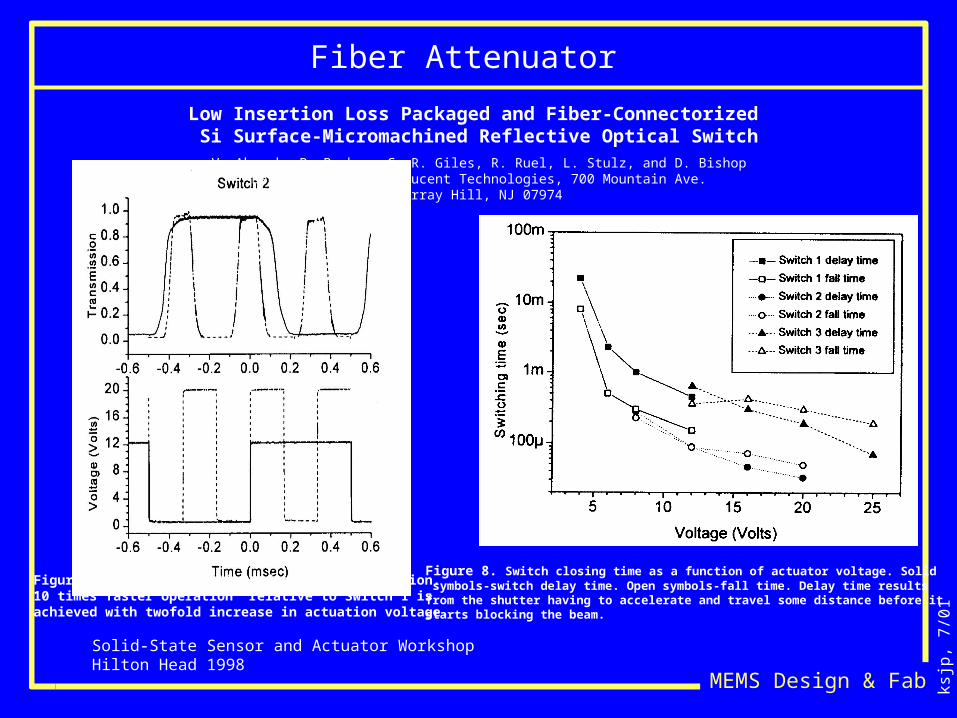
Fiber Attenuator
Solid-State Sensor and Actuator WorkshopHilton Head 1998
Low Insertion Loss Packaged and Fiber-Connectorized Si Surface-Micromachined Reflective Optical Switch
V. Aksyuk, B. Barber, C. R. Giles, R. Ruel, L. Stulz, and D. BishopBell Laboratories, Lucent Technologies, 700 Mountain Ave.
Murray Hill, NJ 07974
Figure 7. Second generation, fast switch operation. 10 times faster operation relative to Switch 1 is achieved with twofold increase in actuation voltage.
Figure 8. Switch closing time as a function of actuator voltage. Solid symbols-switch delay time. Open symbols-fall time. Delay time results from the shutter having to accelerate and travel some distance before it starts blocking the beam.
ksjp
, 7/0
1
MEMS Design & Fab
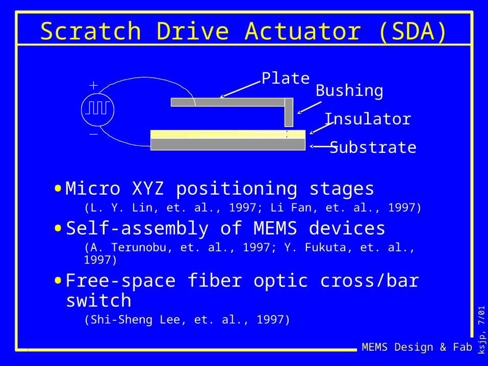
Scratch Drive Actuator (SDA)
Insulator
Substrate
PlateBushing
• Micro XYZ positioning stages(L. Y. Lin, et. al., 1997; Li Fan, et. al., 1997)
• Self-assembly of MEMS devices(A. Terunobu, et. al., 1997; Y. Fukuta, et. al., 1997)
• Free-space fiber optic cross/bar switch
(Shi-Sheng Lee, et. al., 1997)
ksjp
, 7/0
1
MEMS Design & Fab
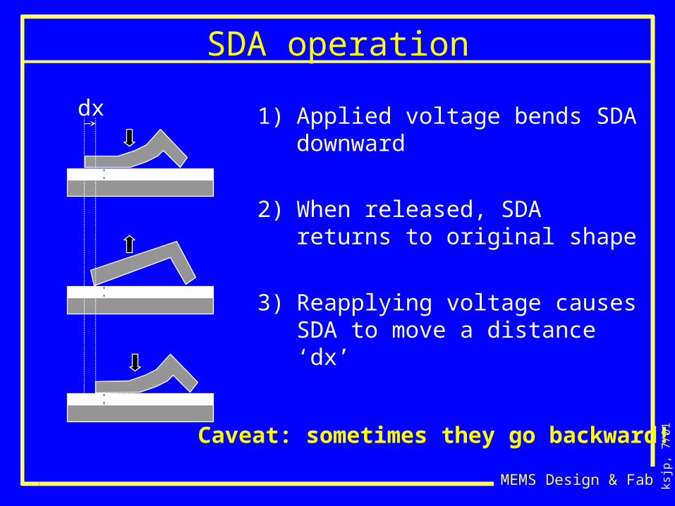
SDA operation
1) Applied voltage bends SDA downward
2) When released, SDA returns to original shape
3) Reapplying voltage causes SDA to move a distance ‘dx’
dx
Caveat: sometimes they go backward!
ksjp
, 7/0
1
MEMS Design & Fab
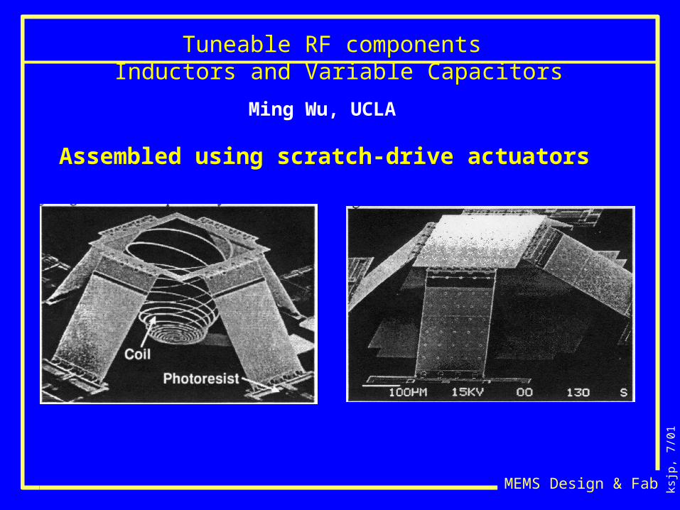
Tuneable RF components Inductors and Variable Capacitors
Ming Wu, UCLA
Assembled using scratch-drive actuators
ksjp
, 7/0
1
MEMS Design & Fab
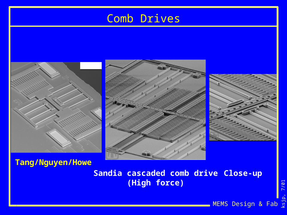
Comb Drives
Sandia cascaded comb drive(High force)
Close-upTang/Nguyen/Howe
ksjp
, 7/0
1
MEMS Design & Fab
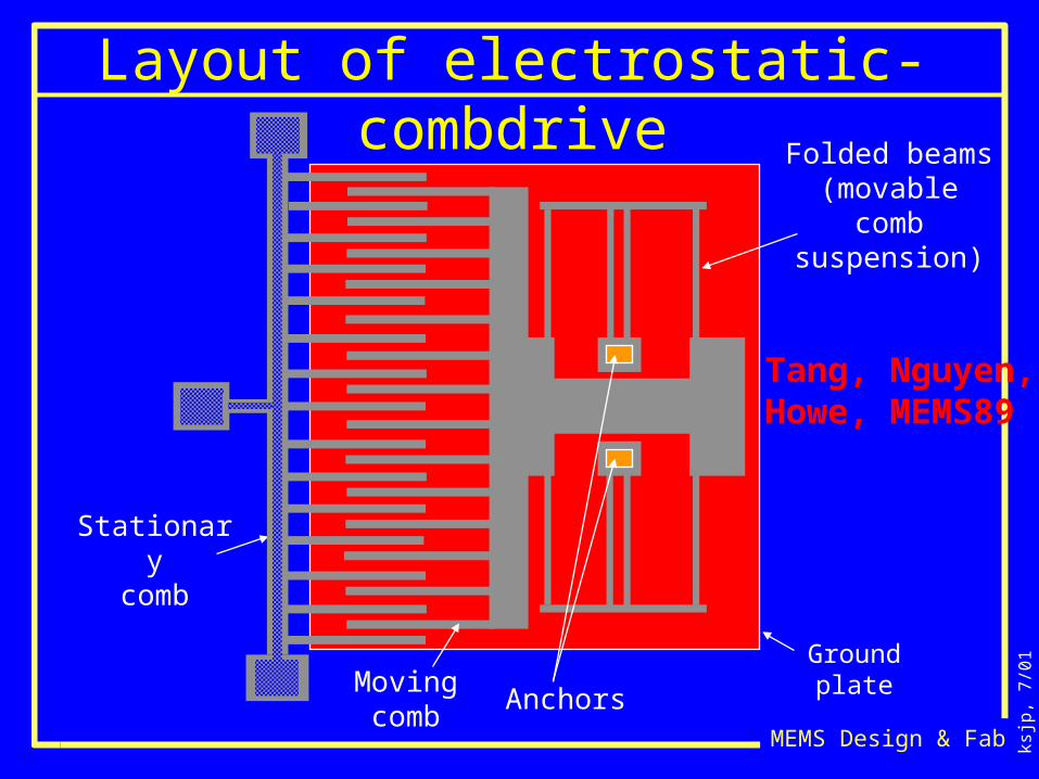
Layout of electrostatic-combdrive
Ground plate
Folded beams (movable comb
suspension)
Anchors
Stationarycomb
Movingcomb
Tang, Nguyen, Howe, MEMS89
ksjp
, 7/0
1
MEMS Design & Fab
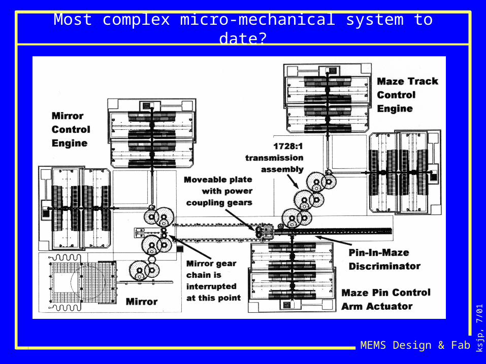
Most complex micro-mechanical system to date?
ksjp
, 7/0
1
MEMS Design & Fab
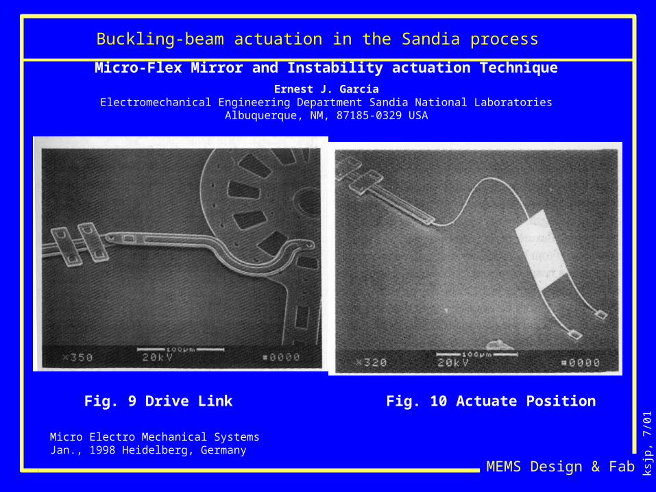
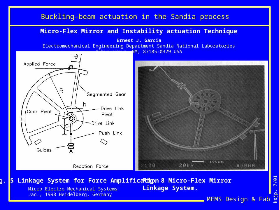
Buckling-beam actuation in the Sandia process
Micro Electro Mechanical SystemsJan., 1998 Heidelberg, Germany
Micro-Flex Mirror and Instability actuation Technique
Ernest J. GarciaElectromechanical Engineering Department Sandia National Laboratories
Albuquerque, NM, 87185-0329 USA
Fig. 9 Drive Link Fig. 10 Actuate Position
ksjp
, 7/0
1
MEMS Design & Fab
Buckling-beam actuation in the Sandia process
Micro Electro Mechanical SystemsJan., 1998 Heidelberg, Germany
Micro-Flex Mirror and Instability actuation Technique
Ernest J. GarciaElectromechanical Engineering Department Sandia National Laboratories
Albuquerque, NM, 87185-0329 USA
Fig. 5 Linkage System for Force Amplification Fig. 8 Micro-Flex Mirror Linkage System.
ksjp
, 7/0
1
MEMS Design & Fab
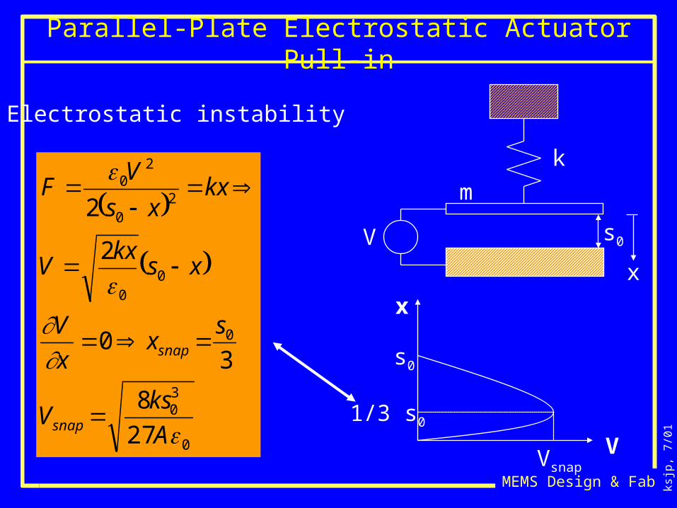
Electrostatic instability
Parallel-Plate Electrostatic Actuator Pull-in
s0
0
30
0
00
20
20
27
8
30
2
2
A
ksV
sx
x
V
xskx
V
kxxs
VF
snap
snap
k
m
x
V
V
x
s0
1/3 s0
Vsnap
ksjp
, 7/0
1
MEMS Design & Fab
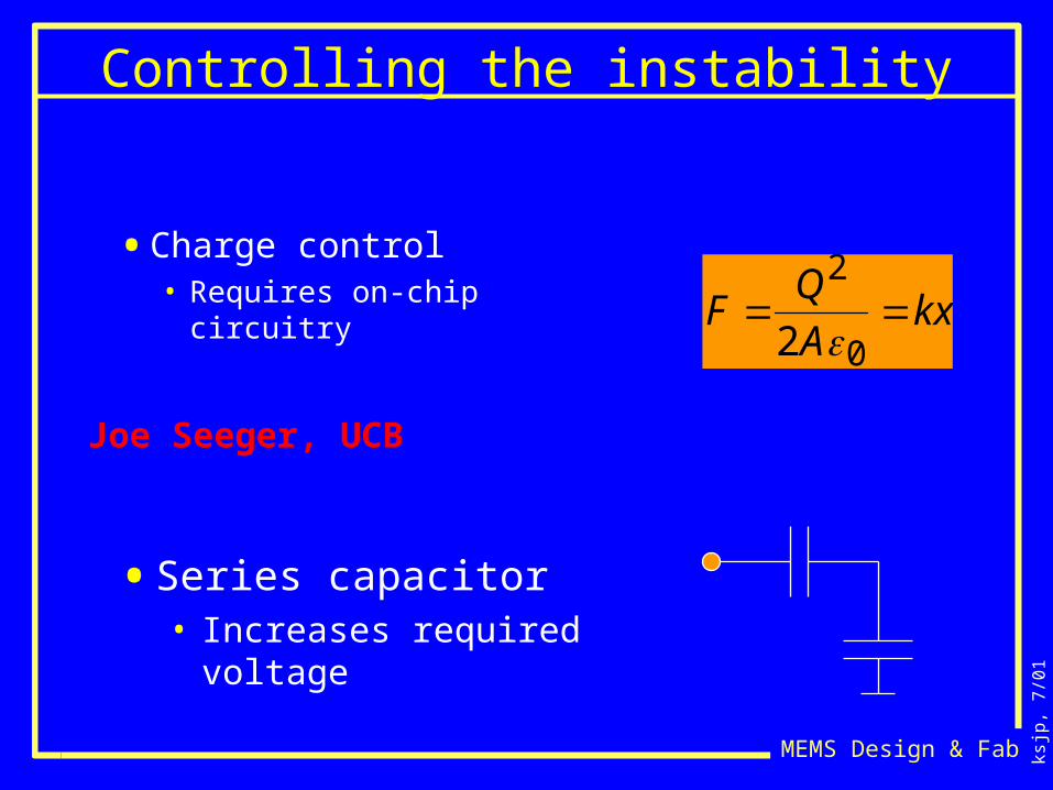
Controlling the instability
• Charge control• Requires on-chip circuitry F
Q2
2A0kx
• Series capacitor• Increases required
voltage
Joe Seeger, UCB
ksjp
, 7/0
1
MEMS Design & Fab
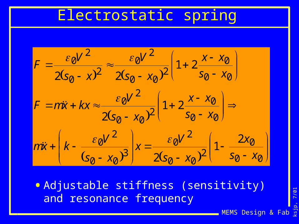
Electrostatic spring
00
02
00
20
300
20
00
02
00
20
00
02
00
20
20
20
21
2
212
2122
xs
x
xs
Vx
xs
Vkxm
xs
xx
xs
VkxxmF
xs
xx
xs
V
xs
VF
• Adjustable stiffness (sensitivity) and resonance frequency
ksjp
, 7/0
1
MEMS Design & Fab
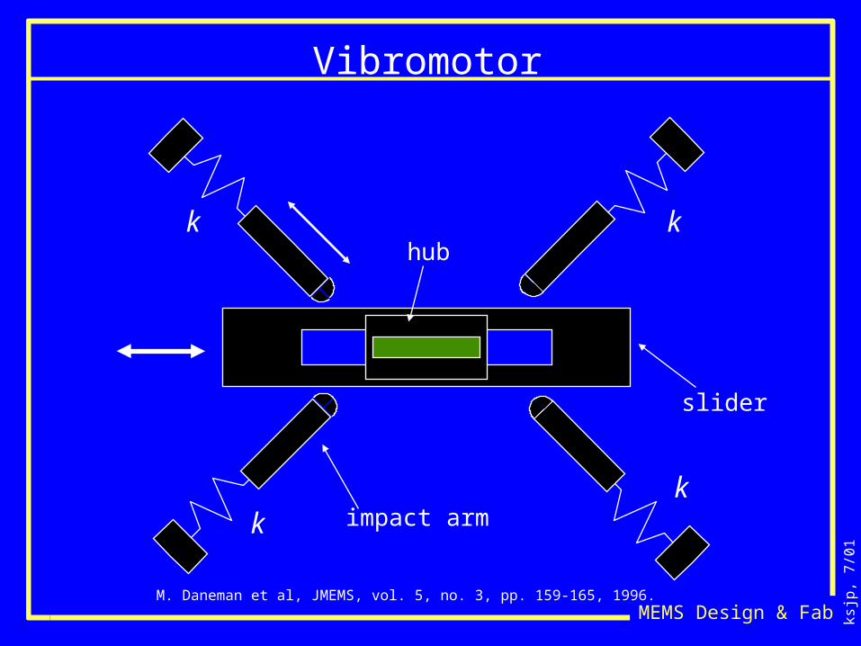
Vibromotor
k
k
k
khub
slider
impact arm
M. Daneman et al, JMEMS, vol. 5, no. 3, pp. 159-165, 1996.
ksjp
, 7/0
1
MEMS Design & Fab
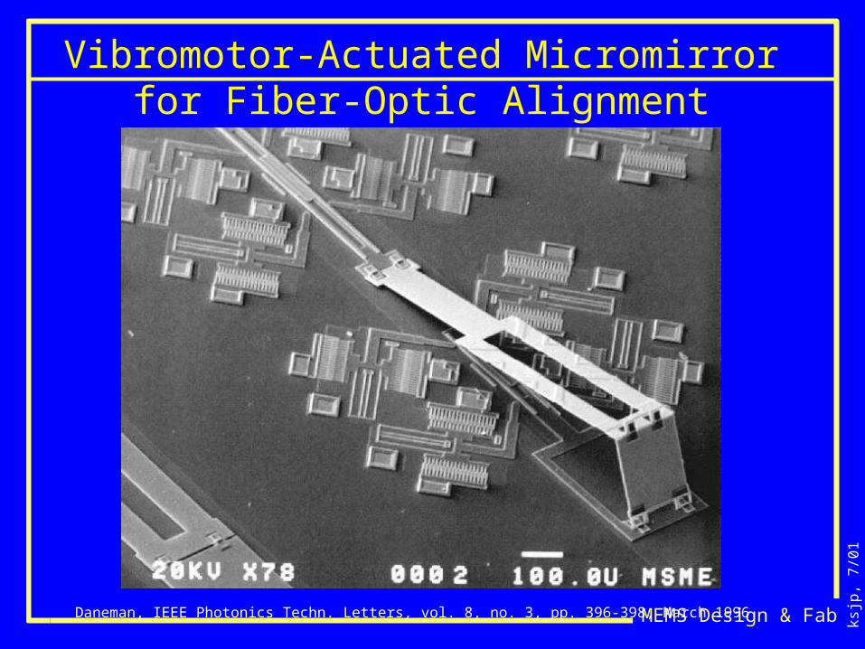
Vibromotor-Actuated Micromirror for Fiber-Optic Alignment
Daneman, IEEE Photonics Techn. Letters, vol. 8, no. 3, pp. 396-398, March 1996.
ksjp
, 7/0
1
MEMS Design & Fab
Summary
• Electrostatics use moderate to high voltage• Force goes as V2/g2 • Paschen limits convenient voltages to 200• Force is scale independent
• Easy process integration
• Many mechanism options