Embed Size (px)
Citation preview

KR9700292
KAERI/RR-1720/96
The Development of Advanced Robotics
for the Nuclear Industry
mn m
The Development of Robotic System for Inspecting and
Repairing NPP Primary Coolant System of High-Level
Radioactive Environment
7]
7]
29 ~ 0 I

KAERI/RR-1720/96
The Development of Advanced Robotics
for the Nuclear Industry
gg
The Development of Robotic System for Inspecting and
Repairing NPP Primary Coolant System of High-Level
Radioactive Environment
7]

1997. 7. 20
-8-
711

1996. 7. 21 ~1997. 7. 20
H.
^- -5J-7}-
7}
71-
- 1 Ji^ 5ft
- i -

m.
(1)
fe 3\**1-
- ii -

(2)
S. 71HS-S1
S.fi.S.
- in -

iv.
(1)
8m
8051^- vHig-AV-a^.^ 5962R9563801QQX =
^-(Divergency)
Window NT
RS-232C IJ-^A
- iv -
(2)
SiLB.
71 #
6
- v -

V.
(1)
S. 60
(2)
tt
- VI -

- vii -

S U M M A R Y
I . Project Title
The Development of Robotic System for Inspecting and Repairing
NPP Primary Coolant System of High-Level Radioactive Environment
n . Objective and Necessity
Possession of stable and lucrative energy resources are essential for
the economical development of the nation and the highly modern living
of her people. Korea has insufficient energy resources because of the
nature of the land. Above 50 percents of the electricity consumed
across the country are supplied by nuclear power plants (NPPs). The
Korean government has realized that it is important to efficiently
manage and maintain NPPs in Korea and to improve their safety for
the national security and development. Of particular importance is the
development of technology for emergency response such as robotic
inspection and maintenance to be used in nuclear hazardous
environments.
Many researchers have been involved in developing remote
technology for use in hazardous environment. However, the robotic
technology for nuclear industry applications developed in Korea is
- vi11 -

currently in the early stage compared with advanced one of foreign
countries.
The use of a robotic system in nuclear hazardous environemnt has
the advantages of watching and inspecting the NPP safety-related
equipment systematically and repairing damaged parts efficiently,
thereby enhancing the safe operations of NPPs as well as reducing
significantly personnel's dose rate to radioactive environment. Key
technology achieved through the development of such robotic system
can be used for aiding the rehabilitation of the industrial disasters and
can offer new approaches to many of the tasks faced to the industry
as well.
This project aims at developing a robotic system to automatically
handle inspection and maintenance of NPP safety-related facilities in
high-level radioactive environment. This robotic system under
development comprises two robots depending on application fields - a
mobile robot and a multi-functional robot. The mobile robot is
designed for use in the area of the inspection and maintenance of the
primary coolant system during the normal operations of PHWR
(Pressurized Heavy Water Reactor) NPPs. The multi-functional robot
is designed for performing the inspection and maintenance tasks of the
steam generator (SG) U-tubes and nuclear reactor vessel heads during
the overhaul periods of PWR (Pressurized Water Reactor) NPPs.
- ix -
M. Scopes and Contents
This research is planned to be performed during the period July 21,
1996 through July 20, 1999. The work conducted in the first year of
the project from July 21, 1996 through July 20, 1997 covers the
analysis of the application field and the design of the mechanical
hardware and control system. The construction of the overall robotic
system with its control softwares is implemented in the second year.
In the final year of the project, the performance and capabilities of the
developed robotic system are verified through field tests.
(1) The Development of a Mobile Robot for Inspecting
and Repairing Primary Coolant System
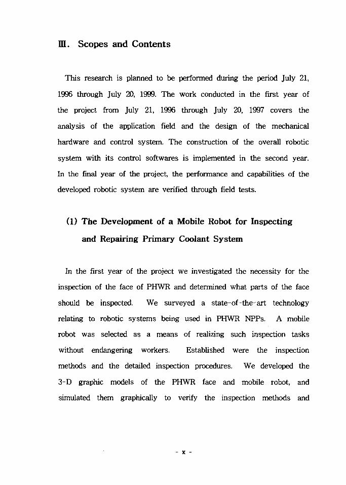
In the first year of the project we investigated the necessity for the
inspection of the face of PHWR and determined what parts of the face
should be inspected. We surveyed a state-of-the-art technology
relating to robotic systems being used in PHWR NPPs. A mobile
robot was selected as a means of realizing such inspection tasks
without endangering workers. Established were the inspection
methods and the detailed inspection procedures. We developed the
3-D graphic models of the PHWR face and mobile robot, and
simulated them graphically to verify the inspection methods and
- x -

procedures determined. Results obtained from the graphic simulation
were used to develop a complete mobile robot. Finally, we designed a
conceptual mobile robot which consists of mobile platform, camera and
extendable arm. An extendable arm mounted on the base of the
mobile platform was designed to support camera on its end, and its
partial construction was conducted.
(2) The Development of a Robot for Inspecting and
Rearing SG and Reactor
A state-of-the-art technology was surveyed relating to robotic use
in the inspection and repair work of the NPP SGs and reactor vessel
heads. Specifically, we investigated the necessity and feasibility of a
robot to Kori PWR NPP. A robot was required to perform tasks such
as the inspection and repair of the SG U-tubes and the sleeves of the
control rod driving mechanism of the reactor vessel head. We
developed a 3-D graphic environment of the SG and reactor vessel
head, we designed a robot capable of performing those tasks through
graphical simulation. A force reflecting master manipulator was
designed to remotely control the designed robot located in task
environment. In addition, we designed a bilateral control system for
teleoperation. Finally, we also developed a training simulator enabling
an operator via a real master to graphically try out and train for
remote tasks in virtual environment.
- xi -

IV. Results
(1) The Development of a Mobile Robot for Inspecting
and Repairing Primary Coolant System
A mobile robot was designed to enable to inspect the PHWR face
and to repair its damaged parts. This mobile robot was designed so
that it can move with mobility in unstructured environment and so
that it can carry an extendable arm on its base. The design was
made in more detail through a graphic simulation to have a maximum
stability of the robot during navigation for two cases - for the case
which it passes through ditches and for the case which it rotates with
a full stretch of the extendable arm. In addition, considered are how
feasible it is to tasks and how efficient it performs tasks.
The designed mobile robot employed crawler type of wheels in order
to pass through a ditch (75 cm in length and 25 cm in depth). A
camera with a pan/tilt motion was designed to be mounted on the top
of the extendable arm which can be extended up to 8 inches vertically
from the base. The extendable arm can guide a camera to the PHWR
front face such that the operator can inspect a total number of 360 of
the pressure tube ends one by one controlling the camera.
The mobile robot was designed to be operated by both a remote
control and a supervisory one. A remote control system embedded on
- xi i -

the robot platform utilizes a radiation-hardened processor,
5962R9563801QQX (radiation-hardened 8051), manufactured by UTMC.
This control system employs a redundancy to overcome the failure of
parts and a divergency to minimize the possibility of failing parts. A
supervisory control system uses a industrial PC operated with
Windows NT. Communication between two control systems is
managed through a RS-232C.
(2) The Development of a Robot for Inspecting and
Rearing SG and Reactor
A multi-functional robot was designed to be capable of inspecting
and repairing the safety-related equipment such as the SGs and
reactor vessel heads of the NPP primary coolant system. This robot
was designed on a basis of its kinematic analysis considering its
workspace, maximum payload, and maximum speed and acceleration.
The robot was simulated in the graphical task environments of the
SGs reactor vessel head models to examine if the designed robot
performs successfully given tasks. The robot controller design was
based on its radiation hardness to radioactive task environment. Task
scenario and its strategy were determined through a graphic simulation
of the inspection and repair procedures.
A force-reflecting master manipulator that is a man-machine
interface device that allows real-time interaction between the operator
- xiii -

and the slave manipulator was designed. This master reflects contact
forces generated by an interaction between the slave's end-effector
and the environment back to the operator, and assists him/her to
accomplish a high fidelity of teleoperation with ease and comport. This
equipment was designed to have a full 6 dof to specify a unique
spatial position and orientation and provide good backdrivability by
minimizing friction and inertia by use of cables. In addition,
considered are a mechanical decoupling of the position and orientation
of the hand for fast kinematic and dynamic models, and a mechanical
counterbalance to reduce the operator's fatigue and improve his
maneuverability. It also features a common interface to control
dissimilar robots. A training simulator enabling the operator to
graphically try out and train for remote tasks that the real slave
manipulator will perform was designed. This training simulator will
allow the operator through a real master to manipulate a virtual robot
located in virtual task environment.
V. Applications and Future Plans
(1) The Development of a Mobile Robot for Inspecting
and Repairing Primary Coolant System
The development of this mobile robot was proposed by Wolsung
- xiv -

NPP. This robot, after completion, will be tested in Wolsung Unit 3
under construction to verify its performance and capabilities. Finally,
it will be applied to Wolsung Unit 1 for practical use. To this end
we completed a conceptual design of the mobile robot this year by
having a close contact with personnels of Wolsung NPP and by
analyzing the task environment of the PHWR face. All the electronic
components of the mobile robot are planned to have radiation-hardened
tests in Korea Atomic Energy Research Institute (KAERI). And then,
this robot will be tested on the full scale mock-up of the PHWR face
of Wolsung Unit 3 before it is put into service.
(2) The Development of a Robot for Inspecting and
Rearing SG and Reactor
The multi-functional robot under development will be tested on the
full scale mock-ups of the SG and the reactor vessel head, verifying
its performance and capabilities. And then, this robot will be applied
to the practical inspection and maintenance operations in Kori Unit 1.
The significance of development is in possessing our own technology
in areas of robotic inspection and repair of nuclear hazardous
environments, thereby reducing financial burdens due to the
introduction of related technology, increasing the longevity of NPPs
through continuous maintenance as well as strengthening the
competitiveness of nuclear power on markets.
- xv -

CONTENTS
Chapter 1. Introduction 1
Section 1. Background 1
Section 2. Objective and Scope of Project 4
Chapter 2. Overview of the State-of-the-Art Technology — 6
Section 1. A Mobile Robot for inspecting and Repairing
Primary Coolant System 6
Section 2. A Robot for Inspecting and Repairing SG and
Reactor 21
Chapter 3. Contents and Results of Project 47
Section 1. A Mobile Robot for inspecting and Repairing
Primary Coolant System 47
1. Introduction 47
2. Design Criteria and Task Procedures 48
3. Graphic Simulation 58
4. Robot Mechanism 66
5. Robot Control System 94
6. Force-Reflection Control of Mobile Robot 103
XVI

7. Conclusions 116
Section 2. A Robot for Inspecting and Repairing SG and
Reactor 117
1. Introduction 117
2. Task Analysis and Graphic Simulation 118
3. Electrically Driven Robot : Design and Dynamic Analysis
1 2 9
4. Robot Control Algorithm 143
5. Training Simulator 147
6. Force-Reflecting Handcontroller 187
7. Conclusions 225
Chapter 4. Achievements and Contributions 226
Section 1. A Mobile Robot for inspecting and Repairing
Primary Coolant System 226
Section 2. A Robot for Inspecting and Repairing SG and
Reactor 228
Chapter 5. Applications and Future Plans 230
Section 1. A Mobile Robot for inspecting and Repairing
Primary Coolant System 230
Section 2. A Robot for Inspecting and Repairing SG and
XVI1
Reactor 231
Chapter 6. References 232
XVI11

1 ^
2%
2.
3.
4.
5.
6.
7.
4 2
1
4
6
6
* #7^2. %%2-^r S.S.S. 21
Ml-g- 9J 4 47
i ^ ^ ^ ^ U S - 47
47
48
58
66
94
103
116
117
117
XIX

2.
3.
4.
5.
6.
5
1
2
118
129
143
147
187
225
226
226
228
230
230
231
232
XX

2.1.1. *l*l-3. £l-sl ^ a 7
2.1.2. «x}3. 9
2.1.3. «U"3#^ afli^^l 10
2.1.4. n^S. 3.q%*]4\ ^2: 12
2.1.5. «q«3S. S^^-ul5l afl l 13
2.1.6. «*<££- S L ^ H ] «l|s. l ^ ^ ^ l 13
2.1.7. ^ ^ 5 . HSJI^uls} ?fle)xl ^-fl^.^ 14
2.1.8. CIGAR >-g-ofl (I) 16
2.1.9. CIGAR 4-§-i (H) 16
2.2.1. 1^ri1 €^>5. ^ ^ 23
2.2.2. €^}5. ^|HSl #&S. 24
2.2.3. <k$».7} ^ & 4)o]%-7-^*} &tt 25
2.2.4. ABB ^ < H * T L ^ ^ - * ' 1 W 4 ^4-8- S A S . A ] ^ ^ — 27
2.2.5. ABB S 1 I *iH-g-7"§^*l ^-^-^(Without sleeve) ^^> 28
2.2.6. ABB SJ iS . ^]<^^.^^.^-^ ^-^-^-(With sleeve) ^A> - 28
2.2.7. # 3 J E L - < H C 3 ^ ?>^ #^§ 1 29
2.2.8. Mitsubishi £-2.E.4\ ^tt&Q*) ^*-¥- ^ 4 31
2.2.9. ^^}S. 1 } 31-f 36
2.2.10. &7)ig$7] ifl^-^2: 37
2.2.11. ^-«. JE<H1 -?-3)-€ ^ " S ^ 4 ^ 39
2.2.12. ZETEC SM 5.£ 42
2.2.13. ROSA m 45
XXI
2.2.14. ROSA m *1<H7l 45
2.2.15. ROSA HI # e ] ^ f l o W ^ 46
3.1.1. ^<g £*1 (I) 55
3.1.2. * ^ £*1 (H) 56
3.1.3. **<$ £*i (HI) 57
3.1.4. 3.SLS. * l#«JMiH^ ^ 59
3.1.5. #° f l l - ^^^1^1 S.JiM 4^1 61
3.1.6. * -i-4 *l-i:elM# 633.1.7. 7>Bflef# o|-g.# ^ ^ ^ ^ Al#«flo|^ 66
3.1.8. 5 . J i ^ 71^-^- *J*fl ^ ^ JE 68
3.1.9. o l ^ s } ^ ^ - 4 ^A-^J£ 71
3.1.10. «>]*•¥• &*A ^ T ' -^ -S-^ ufl^l^ 73
3.1.11. * f l J&sl ^M}5. 73
3.1.12. ^ i s l > >H1J£ 74
3.1.13. ?Hef W ^ M ^ ^ - ^ ^ 80
3.1.14. < ei 7 H §Eflo] a . ^ 3 . <a tl-fl 83
3.1.15. ^ ^ a . <a E]-^al A>-§- o| 84
3.1.16. ^ 1 ^ °J- ^ £ . S . 4 O ^ 7-^S- 88
3.1.17. M - S ^ ^>Ml£ 91
3.1.18. ^ l l ^ ^ l ^ ^ 4 ^ ^ 1 92
3.1.19. iaf^sl m 0]$ ^A £ 93
3.1.20. o l*3JLS. *\]°]A)^<i2) ^HT^S. 94
3.1.21. ^e]^o]-^s) ^ A J £ 95
3.1.22. #2^H-¥-S) ^r-M¥ 96
xxii

3.1.23. ^ ^ W ^ M I %^%tf -a^l 973.1.24. 4°)7}2] 7l£-7l^ 100
3.1.25. *lH7l£] J i^-^-4 101
3.1.26. c-llo]^ °,mi?-<>\ Redundancy^ Diversity 102
3.1.27. -£3 2 : ^ * 1 ^ ^ S . 103
3.1.28. ^?fl€ S ° l ^ £ ) #££. 106
3.1.29. %#¥ yq 109
3.1.30. KAEROT ^ A>^1 HI
3.1.31. 111 £^ ^#*1 ^-^5. 112
3.1.32. S L S ^ ^ 1 4 H4
3.1.33. PC # 5 L ^ «r^ ^<Hl^ ^ ^ € ^ « > ^ * H 7 | 115
3.2.1. ^ 7 1 ^ 7 1 v f l - ^ -^^ S.JS.JE ^ ^ 1 7fl^JE 120
3.2.2. 5 . ^ . ^ ^ 3*K1 3.$^ S .1 122
3.2.3. ^ 7 1 ^ ^ 7 1 ( 3 . ^ "F" ) 3 *R1 ^-«fl^ 5Lt 123
3.2.4. - 7.1-s. 8(]^ 3 *M mm S.*£ 124
3.2.5. 7fl^-i^m 5-iLS.^ 7}^^^ 4%. 126
3.2.6. ^ 7 m ^ 7 | ^ ^ ^ . ^ 2]-<a A^eilc)^ 127
3.2.7. #*}£- nB. ^ ^ ^ . - r ^ ^ ^l"Bflol^ 128
3.2.8. £110] 7 l £ ^ 130
3.2.9. 1 ^ ^ ^ ^ - i&^£ 133
3.2.10. 2, 3, 4, 5 # ^ ^ ^ - ^ ^ - ^ £ 134
3.2.11. 6#-£r ^ -^ -^ ^ - ^ ^ 134
3.2.12. £\#^s\ %3- £.# 139
3.2.13. 3#^r43 ^S. i?!: 139
XXI11

3.2.14. S)#zHr£S| 33. iL# 139
3.2.15. iies] s^£ 141
3.2.16. *&AQ SJS.^^ ^ T f l i 142
3.2.17. Computed S5 .3 . * H i-^- t ^ H ^ 144
3.2.18. Joint *W*] 1"P- H ^ 145
3.2.19. 7 > ^ ^ ^ A]^<q 7fl^£ 148
3.2.20. «£-f s] ^ -^ 151
3.2.21. Boolean ^^> 159
3.2.22. Boolean < S ^ ^ . 9 . i # £ 160
3.2.23. 2]^?>^ ^iTiel 168
3.2.24. Convex ^ ^ 173
3.2.25. Concave ^ 173
3.2.26. ^ sg^4°l^ ^ii^Bj 174
3.2.27. ^^d^^i)- 7l^^E] 180
3.2.28. ^it^S ^^^7l 7fl £ 194
3.2.29. 3 1 ^ ^ ^ 7 1 71^-S}- 195
3.2.30. ^11^3 ^3:471 ^-iTfl *13 197
3.2.31. ^3i^7}$] ^ e f l ^ ^ l l rBl lo l^ 201
3.2.32. 3 : ^ 1 ^ , nfl<g^ U]jiL 204
3.2.33. 6-6^§ ^ f t ^ 1-^lf- 71^-s]- ^ f i ] 205
3.2.34. 7 1 ^ ^ - Bfl 206
3.2.35. ^Tll^^r 211
3.2.36. D.I^ £°1 214
3.2.37. 'gTll'g'rofl 4-g- ^ ^ ^ ^ €<>1 215
XXIV

3.2.38. i ^ ri M 217
3.2.39. 3^>« **<$ °m 219
3.2.40. Spherical 2:91^. ^^] 221
3.2.41. K d ^ - i l - ol-g-* ^ i ^ <*! f H H ^ -i^l 222
3.2.42. ^r^7) $3.4\- ^#O)]O|E-1 223
3.2.43. a ^ € ^ ^ ^ $1*83. ^3:^71 224
XXV

2.2.1. Framatome ^SLJEt- ol-g-^ alH^f ^ f - ^ l #*•¥• 3 4 32
2.2.2. Framatome ^ ' H ^ ^ - ^ ^ ^ ^ f - ^ ^4-§- ^^1 33
3.1.1. ^nflef W I S o^-i-s) 79
3.1.2. 7H|el- W^SSI ^ / ^ ^ - ^ ? > q ^ 79
3.1.3. <?fiS.S. A>^ ^ ^ ^ - o i ^ g j i a 82
3.1.4. -tf-^tf SS£El-<a^ ^ ^ ^ ^ ^ - 88
3.1.5. #^<& ^S.SE]-<a^ «qtg 89
xxvi

s
s. 2.1.1. *u>s *m 83 2.2.1. Mitsubishi 4 ^ ^ M ^ ^ ^ l 34-§- SJ iS . *fl*l 30
3 2.2.2. ^71^-^71 33 -S / r ^ 35
Jt 2.2.3. 5L« "F"^ ^ 7 m ^ 7 l * ( « 40
5 2.2.4. ZETEC SM-23 5-iL^ 4Q 43
6 3.1.1. z>£:ELeH ^ ^ ^ - ^ 1 ^ ^ 3]-<a 48
JL 3.1.2. 7l^3|Si ^ ^ ] 7 l ^ 49
5 3.1.3. S-^Jf^s} ^ 4 ^ 1 *l-8-*l 50
S 3.1.4. ^ ^ i €^161 ^ ^ E ] ^ * 4 - a «1-8-*l 51
S. 3.1.5. *)«• ^ ^ 4 ^ wj-4^ ^-g-^l 51
S. 3.1.6. ^ ^ ^ ^ - a * ^ ^ HW'ti *I-8-*l 53
5 3.1.7. B <=H1 4 ^ - MHJ-4-a 67
3. 3.1.8. 3.SLE 7 1 ^ ^ - *H*I 69
a 3.1.9. o l ^ - f ^1€ 75
IE 3.1.10. CCD 7>*f|2f ^ 1 ^ 78
6 3.1.11. # * # CCTV ^l^s] ^1^[ 78
S. 3.2.1. Denavit-Hartenberg 4 ^ D 1 ^ ^ 130
3. 3.2.2. I l l ^ s l ^o] 130
a 3.2.3. ^ 3 2 ] ^ ^ ^ 1 ^ 135
S. 3.2.4. -Ml-«M4! ^ ^ 141
3 3.2.5. D-H £^r 196
3 3.2.6. i ^
xxvii

50
TMI ( Three MUe Island )
20%
7 1 7 ^
- 1 -

Feeder Pipe ), « *1*1^ ( Pipe support )
Calandria ) ^ M %% 2.^- aj-«g<>l A ^ S ) ^.B.SM1 3 £ 4 .
in Service Inspection
2. ^7m>«7l ^ ^ ^ s ^ ^ J i ^ S-JB.E.
^•(Primary Coolant System)^-
•g- n]*]S.
5U4.
£7]-
5U4. 5.iLS«
- 2 -

ICRP
A]-
A>-§-o)l
ol cf.
71
71
- 3 -

*!l 2
1.
-S-g- S-iLS. A l ^
. o)
2.
- 4 -
5a4.
- 5 -

1. * A
i Mrad
Fail-Safe
A
( Pressure tube W
fe 1 Mrad^ 3.^*}$. *)<%<>.£. Af -o) ^ ^ - ^ ^ $7l
^ nfl 4- .8.31-cK 4
- 6 -

2.
Feeder Hpe
2.1.1 4|
38071)51
2.1.1.
Fig. 2.1.1. Structure of Reactor Building
- 7 -

2.1.2TT
(End Fitting),
380
(Feeder Pipe)'!-
2.1.
JE. 2.1.1. -€
Table 2.1.1. Specification of Reactor Assembly
Total Thermal Power
No. of Channels
Max. Channel Power Nominal
Feul Bundle per Channel
Primary Shutdown System
Secondary Shutdown System
Pressure Tube Material
Calandria Assembly Material
Calandria Tube Material
Core Length
Calandria Assembly inside Dia
2,061.4 MW
380
6.5 MW
12
28 Rods
6 Nozzles
Zr-2.5Nb
SS Type304L
Zircaloy-2
5.94 m
7.595 m
- 8 -

n. « tActw>tv eo»TftOk vm i *
H. SWUTOfFUW1
« . CO"aTIWM. ABSOAvC* t>"*iT
• A l f fCTOM " • " '
2.1.2.
Fig. 2.1.2. Reactor Assembly
- 9 -

5U4.
2* , 0* , -32' , -58° , -90' •§• 77^1
90° , 58° ,3
22 21 20 IS 1* 17 16 IS 14 13 12 11 10 9 • 7 • 5 4 3 2 1
2.1.3.
Fig. 2.1.3. Location of Pressure Tube
- 10 -

It21
2*0^al
( Shielding Door ) <>1 ^4*}^ ^ ^ ^ ja*H^-H]
2.1.5 <>llfe ^j
Maintenance Crane ) 4 £.5i^l7> ^^-S. *\3,
1 ^ J l ( Carrage ) 7>
2.1.4
2.1.6
2.1.7^fe ^ ^ 5 . 5L*\)%*}4\ ?fle)^l <H^#e1 ( Carrage
Assembly )«
( Gimbal ) -8-MS
- II -

2.1.4.
Fig. 2.1.4. Structure of Feulling Machine
- 12 -

REHEARSAL CHANNEL \ T y C ^ B R A
SEftVtCC PORTS
2.1.5.
Fig. 2.1.5. Location of Feulling Machine
RIEUMO IUCHM « « U «5SE«0LY
2.1.6.
Fig. 2.1.6. Feulling Machine Head and Support Cradle Assembly
- 13 -

WWU SUSPilSIOIMilt
rui *r SIIVI unAJMH8IT
isiEt ginASSMIIT
T >II«E EXCOOE1
vrn* «iH»it Din
r Mm
I™ ~ \ MACTOR
tOWII 4IH8M Wll
| * )CA»« I *OI IHOWN
2.1.7.
Fig. 2.1.7. Feulling Machine Carrage Assembly
- 14 -

3.
( Eddy current ) % # ^ &-M- 34-§- 5U±i=4
CIGAR :
( Channel Inspection & Gauging Appratus for Reactors )
( CSA ) s\
Ontario Hydro ^\7\ 1980^^
CIGARETTE ty& ^
147flSi ^<£3. ^&*\) tfl
2.1.84 ^ ^ 2.1.9fe
CIGAR ^ ofl# J5L<H cf. a tflfl-JE.
LSFCR ( Large Scale Feul Channel Replacement )
MAN Energie 3**HMfe Utilitiy 1 A ^ ^ ^«fl CIGAR 4 -
TIGER ( Tube Inspection and Gauging Equipment for Reactor ) 5-iLB.
- 15 -

2.1.8. CIGAR Al~g.4| (i)
Fig. 2.1.8. Example of CIGAR (I)
2.1.9. CIGAR Af^ofl (D)
Fig. 2.1.9. Example of CIGAR (II)
- 16 -

SFCR :
( Single Fuel Channel Replacement )
7] A>-g-Ag ^a jo ] OJ_OT^ *M<3 ^ l - ^ ^ ^ H S CIGAR
2 7 H tfl*|] '94
S ^ l ^ ^ - i - fl* LSFCR ( Large Scale Fuel
Channel Replacement ) °]
: Scrape Sampling
( Chalk River Nuclear Laboratory ) 7\
107fl
Garter Spring $*}&$ SLAR :
( Spacer Location And Repositioning )
Garter Spring*!
- 17 -

5tW, °1* ^1*1-71 fl*H Garter Spring^:
1995V!51*11
a]
^ ^ Garter Spring^ ^ ^ t b # 3 - 5 - 5 . ^ ^ 1 = 1 ^ Sft
Garter Spring^ « 1 ^ ^ ^ ^ - ^ M - ^ 4 *1 SLAR
Garter Spring 4
ASTM A106B ) #
4^)0] C S A S t d
. OJ611
sai996\d5.°11 -8^ ^ i i ^ ^ S . 40 71151
- 18 -

VIT
- R.J. Electronics^^
4.
3 . * ja«r«l-fe ^ 4 ^ E ) 380711S1
21711 S.±i
- 19 -

5a
- 20 -

2 ^ ^71^71
1.
7171S
^(Plugging) 52 ^3^(Sleeving)
. 1991 id
71 (Buggy) 3 3L7] M<HH «•-««• «^>5. -§-7l *fls.
o]6||
- 21 -

4-§-
2.
1991 Vl 9€ 231J 1:^:451 7 ^ ^ ^ S . ^ ^ ^ ^ ^ ^ 4 i < y -¥-71
4 10\! ^7lS- A^Slfe ^^>S- ^^-g-7lSl ^ ^ Al^4>§o|)A
«fl^ ^-^51 ^f^ol ^ ^ 5 . ^-o]s)$i4. o] ^4s . fe 155 Bar
4 ^^-^-^islfe^l 170 Bar ^ i > <y- A 1 ^ 4 207 bar
4 ¥ i i ° l 3-^51^4. 4^1 ^ ^ £ 3 H 3 <y-^iL4 ^^r 150
CCTV1
65 7flfil #Elt iL^ 3
EDF fe * « i ^ ^?1^ -
6l^r 900 MW
- 22 -

3.711 -S^S- H ^ tflJMI "L"
^^-8-71 (Reactor vessel)^ ^ ^ ifl-f^l "C" S 3.*]%.
o] 0^4. 2.2.2 fe ^"^-8-7] Sf l^ 3,4 £71)
2.2.1.
Fig. 2.2.1. Overview of PWR
- 23 -

270*
2.2.2.
Fig. 2.2.2. Top view of the reactor head
- 24 -

Yfe t(Thermal)#elti.7l-
2.2.3
71
01
IQIH
flTAMLSSS STEEL O04U
JJCJUELO
FERprnc STEEL
STAINLE
..tfMl ALLOY
2.2.3
Fig. 2.2.3. CRDM penetration with sleeve
- 25 -
3.
7\. ABB
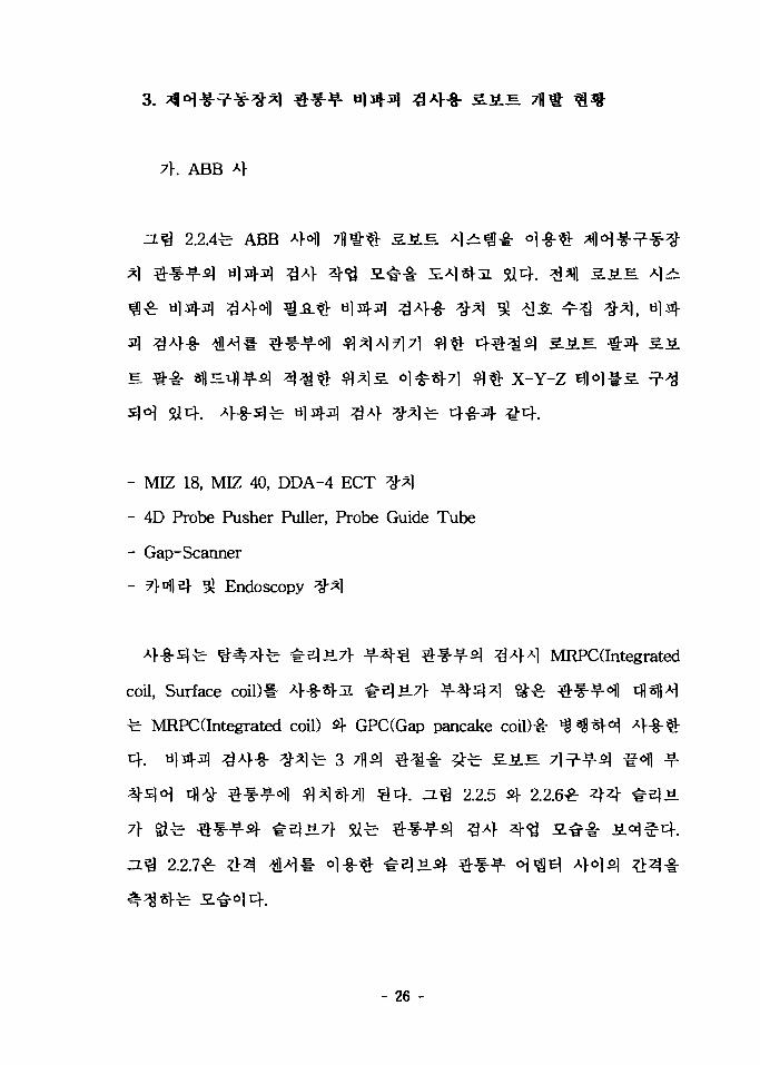
2.2.4^ ABB AH 7 f l t $ ^ . ^ . E A ] ^ ^ ^ - oj-g- V
x-Y-z
- MIZ 18, MIZ 40, DDA-4 ECT ^*1
- 4D Probe Pusher Puller, Probe Guide Tube
- Gap-Scanner
S! Endoscopy #*]
MRPCdntegrated
coil, Surface coil)# 4-8-^3. #51^71- ^ -^-s ]^ ^^r
fe MRPCdntegrated coil) s|- GPC(Gap pancake coil)-i-
fe 3; lo| ^ . ^ ^
3*]«M1 € 4 . ^ . ^ 2.2.5
7r Si^
2.2.7^
- 26 -

Probeholder
Sup
Reaktor VesselClosure Head
Vessel HeadStorage Stand
Manipulator Cross Supon Plate
270° \ ^ ~ \ ~ V / .0"
90°
Manipulator Rotating Capability 360°TKMl
2.2.4. ABB
Fig. 2.2.4. ABB Robot system for CRDM penetration inspection
- 27 -

2.2.5. ABB 3.2£ms] *H-8-nMM|-*l #*§•*?-(Without sleeve)
Fig. 2.2.5. Inspection of CRDM penetration
without sleeve by ABB robot
2.2.6. ABB S-iLJEfi] ^ H - g - ^ ^ l ^ ^ ^ ( W i t h sleeve) ^ 1 -
Fig. 2.2.6. Inspection of CRDM penetration with sleeve by ABB robot
- 28 -

2.2.7. #el«.-
Fig. 2.2.7. Sleeve-Adapter Gap scanner
- 29 -

Mitsubishi
2.2.1
2.2.8^ Mitsubishi
^ Bore, annulus, ale part-length
SIS. Al
£ 2.2.1. Mitsubishi *}s>\ ^ H ^ ^ ^ l ^ 4 - § - 3..S.B.
Table 2.2.1. Specification of the Mitsubishi CRDM inspection robot
^ «
^J^lolEi
^^d^^-g- ^^«H1<>1E^
^ «3,480 x 1,070 mm
250Kgf370
Max. 0.3 rpm
1,640 mmMax. lOOmm/sec.
1 rpm
* ^ - S-EJ230 mm
10 mm/sec.#7} 3_£\
- 30 -

Coot rot unitECT
itiumeniDatar ecord«(
2.2.8. Mitsubishi 3,*LE.2\
Fig. 2.2.8. Inspection of CRDM penetration with sleeve
by Mitsubishi robot
Framatome
2.2.1 £ 5 # ^ Framatome
Mitsubishi
. ABB
- 31 -

5514. A
4
2.2.2
2.2.1. Framatome SiLS.1- «l-8-«-
Photo 2.2.1. Inspection of CRDM penetration by Framatome robot
- 32 -

V 2.2.2. Framatome
Photo 2.2.2. Framatome CRDM penetration inspection deveces
3.
7\.
2.2.9 7}7}
- 33 -

2*}
. ZJ-
o.5. -u"
"U"
ojofl
3)
- 34 -

3. 2.2.2.
Table 2.2.2. Inspection/maintenance tasks on steam generator
Inspection
Cleaning
Repair
Eddy current test
Ultrasonic
CCTV inspection
Tube pulling
Sludge lancing
Chemical cleaning
Plugging
Shot peening
U-bend heat treatment
Nickel electroplating
Sleeving
AVB replacement
Examination
Examination
Examination
Preventive
Preventive
Preventive
Preventive
Preventive
Curative
Curative
Preventive
- 35 -

STOW S8i£RAT0e
««a
2.2.9. -S4S. 1 > 31 f-
Fig. 2.2.9. Primary coolant loop
36 -

Performancedeterioration- Steam pressure- carry-over
StratificationWater - Hammer
Secondary sidedesign
Tube bundlevibrations
Cleanliness
PrimarySecondaryChemistry
Tube plugging- techniques- criteria
Separatoroperation
SG water levelcontrol
Anti vibration bars
Damageto tube bundle- corrosion-wear
Access openingleaktightness
In service inspection
2.2.10. ^71HMJ7}
Fig. 2.2.10. Internal structure of a steam generator
- 37 -

CCTV §•-
4 43iT^ 34
-s. 347}
Length) 347>
47] q<$*] *Ss]3i 5a
2.2.11 4 £ £
S. 2.2.3 4 -Cf. ^ 3
ZETEC 4 4 Westing House 4 ,
Framatome 4 , Q^ Mitsubishi 4^14 7H^€ S.J4S. -i- l >fl
ZETEC, Westing
- 38 -
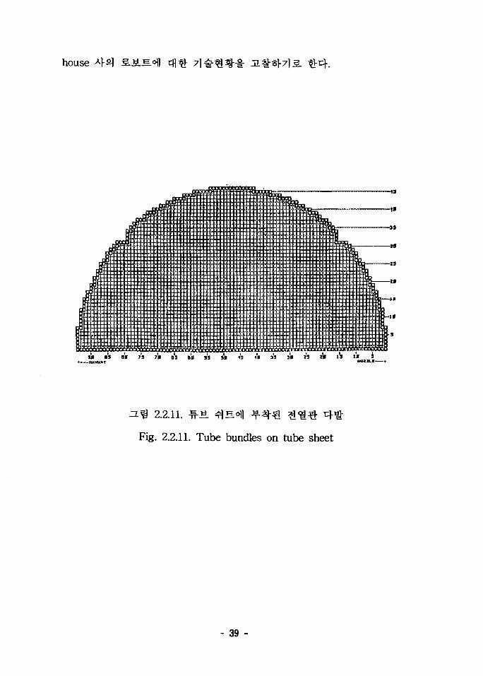
house
jii:::::::::::::::::::::::::::::::::: : : : U s : i ! : ! ! ! ! ! : : ! : : :
:::::::::i:::::::r• • • • • ! : • •>•••*•••••>i k i i a t «>•••••> t i
• •> •< •> • • • • • • • • • • • • • • • AK t t i i l t a • •<•>•• • • • • >•>••>.-,-'ia>>i>aaa>'at •> • • • • • • • • • • • • . ' .; a V
- 3 8
f:i:::::s::::::::::::::::.:::::::,::::::::::::• J : : : : : : : : : : : : : : : : : : : : : : : : : : : : : : : : : : : : : : : : : : : : :::::::::::::::LV
;i::::::::::::::::::::::;:. a : : : : : : : : : : : : : : : : : : : : : :
.'jBiaaBBaaaEaiaaBaaaaaaaaiaaiaaa!{••ii'aiiiaairBiiaiBiBva'aaaiaa'BaaiaaaKBlaaaaaaaiBBiaa laaaaaaaililliaaaaaaaiaaaaaaBBBi iBBBBlaaliaiiiaiaaa
! > • • • • • »»;•_•_•>>.•> < ¥•> H • • • * B • • . " r s V Y V i
iiliiifiiliiiiilliliI::::::::::!:::::::
Ls
M 09 Of 7S 70 B9 Bfl 33 30 13 IB 33 30 « l» 15 l» 3
2.2.11. -W-ti. ^ E O I ]
Fig. 2.2.11. Tube bundles on tube sheet
- 39 -

3. 2.2.3.
Table 2.2.3. Specification of the S/G(model "F" type)
Pitch7 ^
RmaxRmin
Tangent RowUpper
Tangent RowLower
Section TSection W
0.875 ?1*10.050 ?!*10.281 ?1*11.281 ?1*13,388 7i
357.16 ?1^159.844 $1*12.1857 ?!*1
893/888 ?1*121.03 ^1*10.15 ?1*10.22 <?]*1
SA 508 Class 2
49.75 t!*l3/4 "?] 1
1.2812 91*]Round
0.750 ?1^1SA 2845 Gr.C
44 £136 £13 $11 id
o.387 -y^i0.387 <?]*1Inconel 600Alphatized
NominalNominal
7 7ll
Round
- 40 -

(1) ZETEC SM i l l
ZETEC 4 3 SM 4 B] a S.^.^ -2.3. 7fl
30 Kgf
2.2.12
"Camera arm"
arm <H^l-e]^ ECT
"Trunk/manway"
Trunk/manway
Camera
. Arm
^r Si 4 . H * ZETEC 4 3 Eddynet95, Probe Pusher, Acquire,
Inspection Planning system, ^ Inspection Management system ^ ^ ^
2.2.4 ^ SM
- 41 -

Camera armassembly
TrunH/tnanway Hangs
2.2.12. ZETEC SM 3.JLK
Fig. 2.2.12. ZETEC SM Robot
- 42 -

5. 2.2.4. ZETEC SM-23 S.JB.S.
Table 2.2.4. ZETEC SM-23 Robot specification
•¥•711
5LE1
39 Kg
13.6 Kg
24 V(DC)
12 V, Halogen
Sony HVM 52C
# 3 30-60 ?1*1 ^
(2) Westing House ROSA HI
ROSA m £• * 1 ^ Westing House
4.
S J i M S
7 m . ROSA IK ^ ^ 7 1 ^ 7 1
-^•^ e
. ROSA ffl 7>
- 43 -

3} 41 (Plug Removal)
Peening)
2.2.13 £r ROSA III si fil^ o.s.
6
Configuration)* # 1 W . 20,000
^ O . T ^ 30 Kg °11
. 4
^ VME «l^^-5l CPU il^Sl- t ^ o ] j/O
etfs} 7lHV ^5] ^cHAli^AS.-?-Bl ^g^
Ethernet* f-*H «>^^°> ^r^^-^-sl 5 . J £ ; E # ^H«1-JL 1 A ^ tfl
. ^ ^ t } 4 . ^ ^ 2.2.14
2.2.15 fe
- 44 -

2.2.13. ROSA m
Fig. 2.2.13. ROSA HI
2.2.14. ROSA HI
Fig. 2.2.14. ROSA m Controller
- 45 -

2.2.15. ROSA HI
Fig. 2.2.15. ROSA HI Supervisory Controller
- 46 -

1.
71-«
71 .^.
RS-232C
1 MRad
- 47 -

2.
>. 7fl JL
3807113
. a 3.1.
i 3.1.1. ££HeK
Table 3.1.1. Inspection of Calandria Face
- 2l7l] 3 : ^ ^ 7l«H«h^ ^ ^^ r -fr# ^^
- 48 -
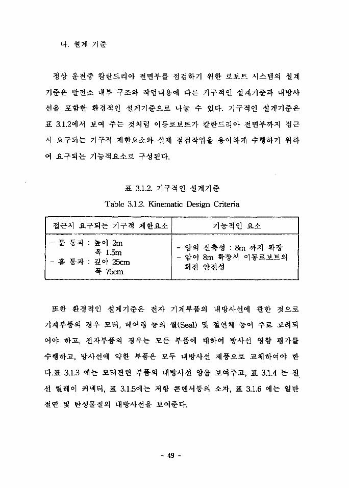
M-.
5 3.1.2. 7 1 ^ ^ ?!
Table 3.1.2. Kinematic Design Criteria
- ۥ ^ 4 : feo] 2m4 1.5m
- * ^ - 4 : ?idl 25cm3- 75cm
7l^3«?! -8-41
- #o} A] 4^^ : 8m 4^1 ^- #°) 8m ^-^^1 °1^3.SLIM
3.1.3
^(Seal)
3.1.4
, S. 3.1.6
- 49 -
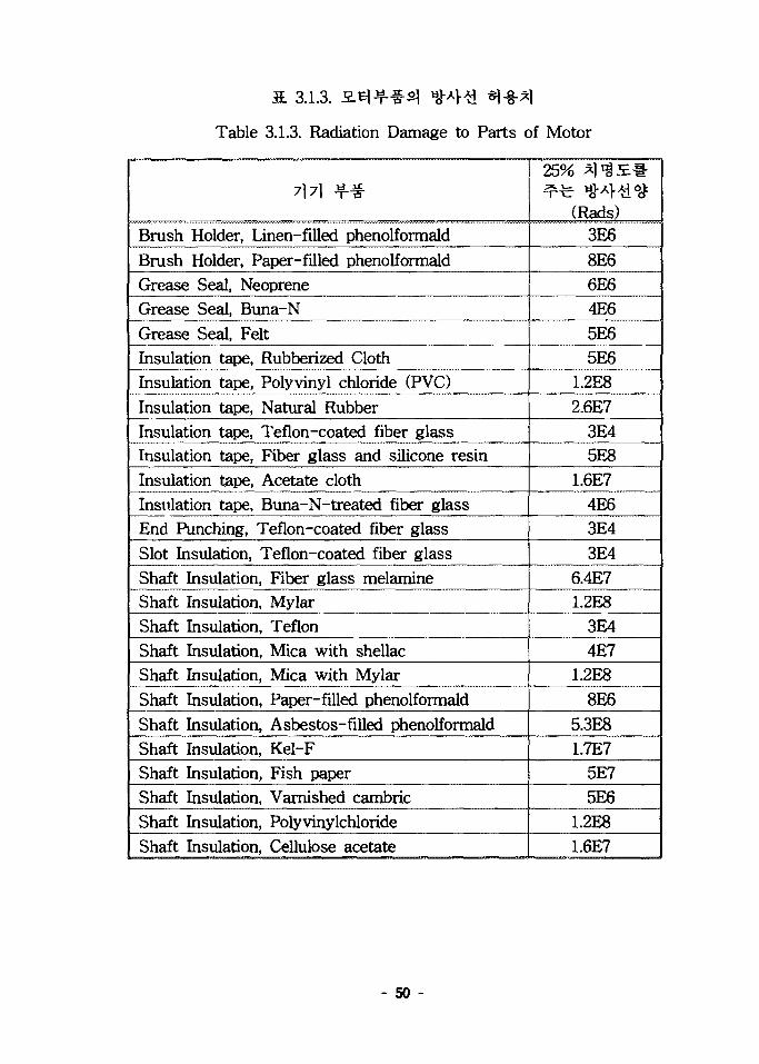
3. 3.1.3.
Table 3.1.3. Radiation Damage to Parts of Motor
71 71 ^
Brush Holder, Linen-filled phenolformald
Brush Holder, Paper-filled phenolformaldGrease Seal, NeopreneGrease Seal, Buna-N
Grease Seal, FeltInsulation tape, Rubberized ClothInsulation tape, Polyvinyl chloride (PVC)
Insulation tape, Natural RubberInsulation tape, Teflon-coated fiber glassInsulation tape, Fiber glass and silicone resinInsulation tape, Acetate clothInsulation tape, Buna-N-treated fiber glassEnd Punching, Teflon-coated fiber glass
Slot Insulation, Teflon-coated fiber glassShaft Insulation, Fiber glass melamineShaft Insulation, MylarShaft Insulation, TeflonShaft Insulation, Mica with shellacShaft Insulation, Mica with MylarShaft Insulation, Paper-filled phenolformald
Shaft Insulation, Asbestos-filled phenolformaldShaft Insulation, Kel-FShaft Insulation, Fish paperShaft Insulation, Varnished cambricShaft Insulation, Polyvinylchloride
Shaft Insulation, Cellulose acetate
25% a l ^ E *
(Rads)3E6
8E66E64E6
5E65E6
1.2E8
2.6E73E45E8
1.6E74E63E4
3E46.4E71.2E8
3E4
4E71.2E8
8E6
5.3E81.7E7
5E75E6
1.2E81.6E7
- 50 -

3.1.4.
Table 3.1.4. Radiation Damage to Wire, Relay, and Connector
Wire Insulation, Teflon
Wire Insulation, Formvar
Wire Insulation, Fiber glass and silicone resinWire Insulation, NylonWire Insulation, NeopreneWire Insulation, PaperRelay, Switch base, Asbestos-filledphenolformaldRelay, Switch base, Unfilled phenolformaldGaskets, Buna-N rubberGaskets, Hycar-PAConnectors, PolystyreneConnectors, Polyethylene
25% *l*8£-t-^ *&*}$.<$
(Rads)3E4
9.7E7
5E84E66E65E6
1E9
1E7
4E63E66E99E7
3.1.5.
Table 3.1.5. Radiation Damage to Resister, Capacitor
71 71 JjLf-
Resister, Carbon composition slug
Resister, Carbon composition film
Resister, Metal filmResister, Carbon filmResister, Oxide filmResister, Wirewound on ceramic
25% a l 'gJE*^ f e *&*}£<&
(Rads)1E71E8
1E111E91E6
1E12
- 51 -

71 7] ^ g -
Resister, Wirewound on epoxyResister, Film potentiometerResister, Wirewound variableResister, Film variableCapacitor, PaperCapacitor, CeramicCapacitor, GlassCapacitor, MicaCapacitor, PlasticCapacitor, Tantalum slug, wetCapacitor, Tantalum slug, dryCapacitor, Tantalum foilTransformers, relayQuartz crystalFoil-clad laminates( Printed Circuit Boards )Connectors, Duroc ceramicConnectors, Melamine plasticSilicon varnish insulationVarister, SiliconVarister, Selenium and copper
25% a i 'SH*
(Rads)1E9
1E71E91E7
1E7
1E101E101E91E71E7
1E91E7
1E91E7
1E7
3E8
3E8
1.4E91E91E5
- 52 -
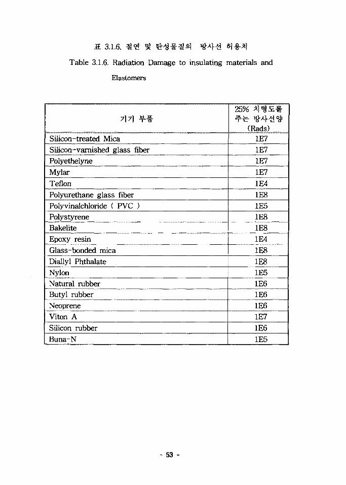
S. 3.1.6. ^<2 ^
Table 3.1.6. Radiation Damage to insulating materials and
Elastomers
7} 7} ^f-
Silicon-treated MicaSilicon-varnished glass fiberPolyethelyne
Mylar
TeflonPolyurethane glass fiberPolyvinalchloride ( PVC )PolystyreneBakeliteEpoxy resin
Glass-bonded micaDiallyl PhthalateNylonNatural rubberButyl rubberNeopreneViton A
Silicon rubberBuna-N
25% *l^:£-&
(Rads)1E71E71E7
1E71E4
1E81E51E81E81E4
1E8
1E81E51E61E61E61E71E61E5
- 53 -

Air Lock AS.
(5)©
- 54 -

3.1.1. 4 ^ *>H (I)
Fig. 3.1.1. Task Procedure (I)
- 55 -

vwrK3.tif
% 3.1.2.
Fig. 3.1.2. Task Procedure (II)
- 56 -
3.1.3.
Fig. 3.1.3. Task Procedure (m)
- 57 -

3.
7\.
nfl-f
s 7
- sis.
- 58 -

Transform* HonBaiw«en
Re»! and Vlrlual Worlds
3.1.4.
Fig. 3.1.4. Configuration of Robot Simulatior
- 59 -

5fl4.
• &
4.
rcj-e}-
5H4.
- 60 -

(c )
(b)
(e)
3.1.5.
Fig. 3.1.5. Robot Configurations while performing obstacle climbing
- o>efl 75cm
3.1.64
- 61 -
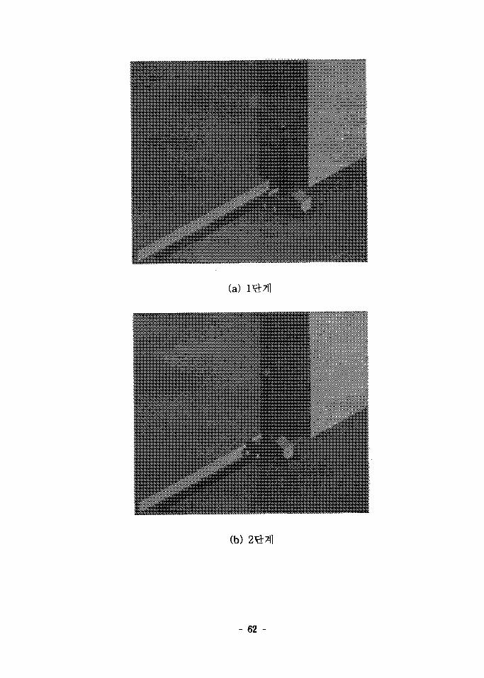
(a)
(b)
- 62 -

(c)
(d)
3.1.6. *
Fig. 3.1.6. Ditch passing simulation
- 63 -

(a)
(b)
- 64 -

(d)
3.1.7.
Fig. 3.1.7. Inspection simulation using camera
- 65 -

4. SJiS
SU4.
7flfo|
3.1.8
- 66 -

3.1.7
( 1 Mrad
fe 1 Mrad
a 3.1.7. 4^] 4#
Table 3.1.7. Radiation dose limits of materials
Material
Carbon steel
Alumina
Silicon rubber
Precision rubber ( O-ring )
Copper OFHC
Nylon
Iron
Radiation dose limit ( rads )
109
10"
10B
5 X 10⁸
2.2 X 10"
10b
2 X 10"
- 67 -

3.1.8.
Fig. 3.1.8. Grobal architecture of mobile robot
- 68 -

S. 3.1.8. 3.SLS.
Table 3.1.8. Specifications of mobile robot
°1 * *
( ? W ^ Pan/Tilt )
7) ^
^ ^ y ^
Arm^ 2.71 ^o]
& *
1 «
7>^^ a.sel-
350 mm
70 Kg
400 mm
1,300 mm
M,M7H;SHf7lr i
500 mm
15 ea
1.0 m
8.5 m
14 Kg
±70°
200 mm
3.8 Kg
S.El,7l<H (Pan, tilt)
87.8 Kg
1.8 m
9.5 m
- 69 -

7\.
o\ 25 cm ^
kg, *fe«l 180 cm
S 1 S 7 } o] ^ -^ -^ f-Jij- 1- nflofl SJSLS
3.1.9 fe 75
Ulllllllllllllllllllll/llllll
I1iiiiiiiiiiii''mil 'inn
- 70 -

—f
WIIIIIUIIIIWI'Illllllllllllllllllllh
i—COIllllllllllillllr/llll,
3.1.9.
Fig. 3.1.9. Mobile robot's ditch passing sequences
- 71 -

DC
€ • § •
±90° 3.
5a4.
, 3.1.11 £
7} 3 3 € ^*«^I -S--MIEO14. a 3.1.9
3 L 1 0
3.1.12
- 72 -

•§-*«3.1.10.
Fig. 3.1.10. Configuration of mobile robot and its driving motors
3.1.11.
Fig. 3.1.11. Details of flip-type arm
- 73 -
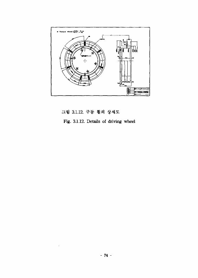
3.1.12.
Fig. 3.1.12. Details of driving wheel
- 74 -

3. 3.1.9.
Table 3.1.9. Specifications of Mobile system
Track size( mm )
Maximum width
Height
Length
Maximum
Normal
Minimum
Weight ( Kg )
Power sourceBattery
AC/DC converter
Vehicle speed ( mm / sec )
Mobility
90° Turn
180° Turn
360° Turn
Slope climbing
Slope travesing
Stair climbingSlope
Turning area (mm'')
Pass through door way ( wide )
Ditch crossing ( mm )
Railroad track
4 €
430
760
1400
1140
760
110
Two 17 AH ( 12V )
120 VAC/24 VDC
0-400
YES
YES
YES
45°
35°
45°
910
460
610
ALL
- 75 -

I t
Pan/TUt 3 3 # * l x r Extendable
40
10 kg o}^-ol s ] ^ , ^l-S-5.S-fB) 9.5
361 5^4. «*f) 7fll&^?l Extendable arm5l ^?fl &%°] 5 kg A
5 kg
5,000
CCD
CCD ^ " f l ^ ^ 7>^^ AI^OIJA^ ef 100 ^
1-^rflalfe 50
109 rad^Ai i
^H^> ^«J CCD
Krad ^A^ CCD 7\
- 76 -

^ 4451
^ DC 24V 4:3 3.^ ( KM3429A
97:1 ) * ^ l ? b ^ ^ 1 ^ ^ : Al~8-*|-5a4. ^"fl^fe WAT-308A
MOTORIZED ZOOM CCTV LENS ( SSL 06072G ) *
->M|-*H ^ ^ 1 * 44^«H a i * } i ^ ^5*4 . Tilting
Tiliting^] ^ ^ ^ H ^ ^Ajzl-o. ±70-71-
3.8 kg oltf. n ^ 3.1.13
- 77 -

3. 3.1.10. CCD
Table 3.1.10. Specifications of CCD Camera
CCD
Horizontal resolution
Minimum illumination
Lens
Fountion
Operating temperature range
Power supply
*fl «1/3 inch, 280K pixels
400 TV lines
0.05 lux at fl.4
CS mount
Auto electronic shutterauto iris
-20° ~ +40° C
12V DC ( 140mA )
3 3.1.11. 3 ^ §• CCTV fcs]
Table 3.1.11. Specifications of Motorized zoom CCTV lens
71 ¥
Model
Focal length ( mm )
Aperture ( F )
Mount
Max. format cover
Filter screw size ( mm )
Dimention ( mm )
Weight ( g )
Zoom
*fl «
SSL 06072G
6.0 - 72
1.2 - 360
CS
1/3"
M49.0 P = 0.75
62.0 x 69.0 x 74.1
600
Mot
- 78 -
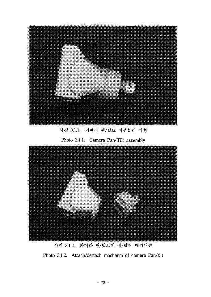
3.1.1.
Photo 3.1.1. Camera Pan/Tilt assembly
Photo 3.1.2. Attach/dettach machasm of camera Pan/tilt
- 79 -

3.1.13.
Fig. 3.1.13. Drawing of camera Pan/tilt
- 80 -

( Extendable arm )
(1)
«• «W
-3 7]
Telescopic arm, Telescopic antenna, Extendable
antenna, Mast ^ cf^tb ^ ^ A S . ^s^ 7\j\ ={•%
sx
Si 4 . ^ ^ 3.1.3 ^r REMOTECA}o?M 7fl## Surveillance robot <>1
iL^^cf. n ^ 3.1.14
, 3.1.15
- 81 -

3.1.3. ««
Photo 3.1.3. Surveillance mobile robot of ANDROS CO
- 82 -

(A-type)
TMM&1SS
HOX-555(B-type)
3.1.14
Fig. 3.1.14. Crank-up tower of variety style
- 83 -

(A style)
m
(B style)
3.1.15. 3.$3. $ ^ ^ ^ A}^- ofl
Fig. 3.1.15. Use example of crank-up tower
- 84 -

(2) 7H1S-
2 kg
3.2 m
kg^l
SEAL
4.
- 85 -

13) 3 # eJS.7]- 75 mm
3 # ^
Power supply!- *}-8-*H ^^^" ^"^ ^ r XlH - ^7fl«|-Sft4.
3.1.12 fe Extendable arm S.S.S,^^ ^Tfls] $#•&, D.% 3.1.16
Extendable arm 5S.£^°J2] ^^1 ^-^JE* 4 ^ 4 . A>?1 3.1.4
Extendable arm 5] ^ f i a ^ * | « ! 1 ^ fl^7l<H
4^! 3.1.5 ^ Extendable arm
- 86 -

3. 3.1.12.
Table 3.1.12. Specifications of Extendable arm Proto type
<>1* #5L
400 mm
1,300 mm
250 mm
4
elJB 75 mm, 3 # 4 ^ 1 -
50 : 1
0 — 75 mm/sec
- 87 -

.yfm^A.
•:rf
U^S
Mt*>
'.In
-r
n_
" ROBOTIC SYSTEM
3 ^ 3.1.16.
Fig. 3.1.16. Drawing of Extendable arm Proto type
A}*! 3.1.4. Extendable arm S
Photo 3.1.4. Transmission part of Extendable arm Proto type
- 88 -

3.1.5. Extendable arm S
Photo 3.1.5. Total view of Extendable arm Proto type
- 89 -

(4)
Extendable arm
51 ^
42, 43,
5 c m
end cap
5 c m
- 90 -

3.1.17 ^r 4 ^ i # ^ V4S.& M-^-ifljl, ^ ^ 3.1.18
3.1.19 fe M ^ i
.L : BRONZQ.Ty : 1 EA
1 /
\ -UJILAS.
ffiWTK
3.1.17.
Fig. 3.1.17. Details of screw
- 91 -

3.1.18.
Fig. 3.1.18. Drawing of locking machanism
- 92 -

3.1.19. ^
Fig. 3.1.19. Nut transmission sequences at screw
- 93 -

5.
7\.
Local Site^ £ ifl«ifl fe Remote site^
3.1.20^
i — , ,—•t_t-.t^-*—~*?a>k
3.1.20.
Fig. 3.1.20. Global architecture of control system for mobile robot
- 94 -
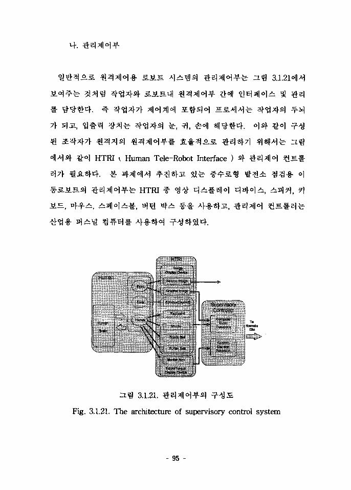
7}-
^-o) HTRI ^ Human Tele-Robot Interface )
JiH, ^1-fi, ^
fe HTRI
o]
l i , ^31) 5 > 71
3.1.21.
Fig. 3.1.21. The architecture of supervisory control system
- 95 -

v V » F I MI «• I .
:r—\i rannlng
3.1.22.
Fig. 3.1.22. The main function of supervisory control system
- 96 -

Dolch 4^1 27fls] Pentium III- *}-§-£}jl 10 #*- i - %# 7}
°1 ?l-€^: Rugged Megapac Potable Computerl- 4-8-*FSi4.
Window NT1- 4-g-^f^^, Visual
RS-232C 3. RS-232C
3.1.23.
Fig. 3.1.23. The Design of supervisory controller
- 97 -

INTEL 8051^
lMrad
S 4-8-^
a ] ^
UTMC
5962H563801QQX
T^fi]
fe -f
- 98 -

(1) *d*HM-£| « * K 1 A &
lMrad °]^ tflHM-SJj- o]^siLS^I| ^ <£^r # 3 . el 4
ANDROS
S ANDROSi ^ - § - ^ 7 ) ^ 4 -frAyisH 7]
-s. 60
711 fe CMOS ( Complement Metal Oxide Semi-
conductor ) ±*\m # £ 7)-^# ^-fe u ^ l ^ ^ ^Hfol^sf JFET ^
^ COTS ( Commercial Off-The-Self )•& ^
(2) M
Safety System °H^ olc] ^7flAH Redundancy^ Diversity
61
71 ^^-ofl ?g7l^A> 71 # ^ 1 7141
- 99 -

i*c
S051
SSBBBBS?
Mem or]
Drivers
D/As / >
a) Dedicated Control Subsystem
3051
Mem or 3
b) Dedicated Data Acquisition Subsystem
3.1.24.
Fig. 3.1.24. The basic function of controller
RS-232C )• W.
- 100 -

vc
8051
MemoT
1 «"' JL
JOJL
1
1 ..../
TDt
b) Data AcqvititiDii SuBisysteMwith Emergency Contrel Bat k ^
3.1.25.
Fig. 3.1.25. The fault tolerance function of controller
Redundancy D/A
Diversity
3.1.26
Redundancy^ Diversity
- 101 -

3.1.26. n°m tm^f-S] Redundancy^ Diversity
Fig. 3.1.25. The redundancy and diversity of data acquisition system
- 102 -

6.
7\. 71) -S-
(master manipulator)
robot)*
Environment
Communicationblock
3.1.27.
Fig. 3.1.27. Block Diagram of Tele-operated System
- 103 -

313 ^ ^ 1 ^ ^ 313
, 7>
^Ji(vision information)^
*W
SI71 nfl£
171
7}
71 el
313
, 5E«-
- 104 -

M * 3}
. 01
814.
•§• 5 7>
AS^ 6]
- 105 -

(spring-damper) H<H $14. el
3^ aoli
5a 1 #±
x ^ ( y
x ^ , y
l ^
DC
3.1.28.
Fig. 3.1.28. Section-Drawing of Designed Joystick
- 106 -

X ^ , y
ffl71
71S]
(3.1.1)
- 107 -

F, :
Fx : S<>1
Fy : ^ 1 ^
ns : ^1^1 1] (sensor beam) 5]
fc?,2 if d^poF ,= (3.1.2)
10 otherwise
I X if , ^
(3.1.3)sgn(x) • Xmax otherwise
oj nfl
p0 : ^ ^ t i . ^l£-f(active window)^
f-^r(saturation function)^)
(3.1.2), (3.1.3) $ zl- S!^!-
- 108 -

DC
3.x]
Mobile robot
3.1.29. ^
Fig. 3.1.29. Force Reflection Method
Coulomb^ Dfl-f
^ s K e l e c t r i c point charge)^
^ (3.1.1)*
i sc^-^s l (spring-damper)
- 109 -

re=JT(q)F (3.1.4)
KQ) '• *}.2Ul<y- *|l(Jacobian matrix)
Q : ^ J U M 4
(3.1.1)
DC 2Z.E}
(3.1.5)
- no -

(1)
3.1.30.
Fig. 3.1.30. Photograph of KAEROT
2.$) ^ ^ 7 l f e 3.7\] 4
SLS)
- I l l -

(a)
A/Dpart
\
\
1 1Joystick
with 2 motors
VxWorks
t\ f
LAN module
>
Visual Display System(UNIX environment)
D/Apart
/
(b)
3.1.31.
Fig. 3.1.31. The architecture of global experimental unit
- 112 -
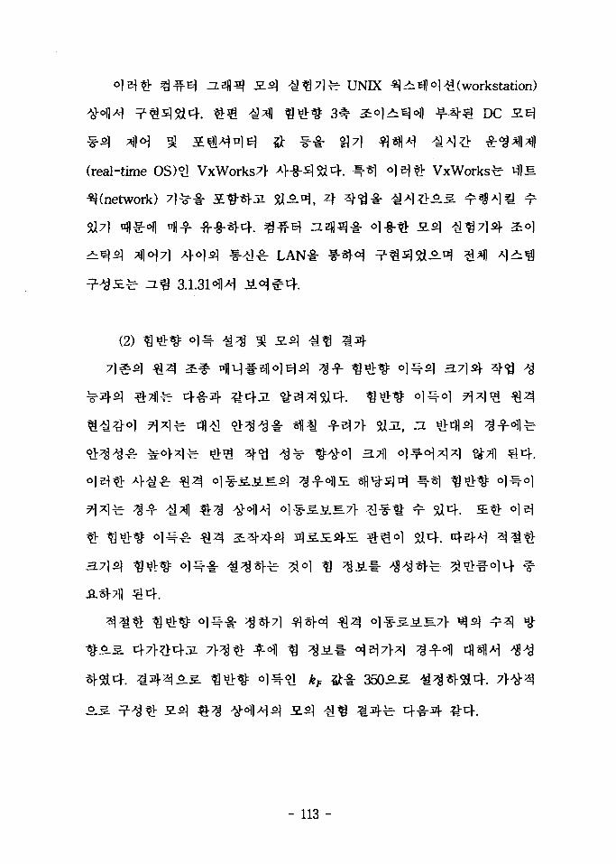
ziafl^ 3-SH ^ 7 ] ^ - UNIX ^9M^(workstat ion)
3 ^ 2:*l^eW JMfr€ DC
(real-time OS)?1 VxWorks7|- A)-g-s]^cf. ^-«| o ]^^ - VxWorks^ i-ilS.
^(network) 7 ] ^ # Hfl-*hai ja^-^, A
3.1.31^]^
(2)
3-A
XI4.
fe 4-8-4
- 113 -
J <\i-
B
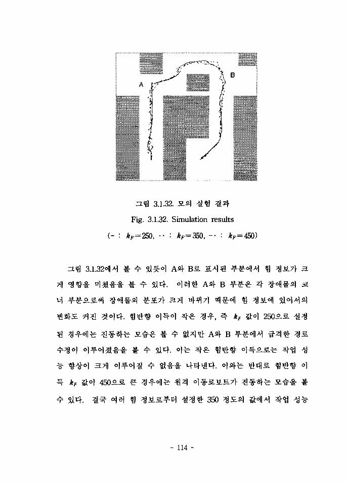
3.1.32.
Fig. 3.1.32. Simulation results
^ kF
3.1.32^^ M. ^ ^ - . o ] A 4
1- ^ 9X4. ^leitb A ^ B
B
^ ^ o ] 250-5-5.
*}
350
- 114 -

KAEROT^ll
(3)
PC
3.1.33. PCS] flJE-f
Fig. 3.1.33. Force reflection controller in window environments
- 115 -

3XA
7}
75cm
71 -
- 116 -

2 ^ ^
1.
(Control rod driving mechanism penetration)
sis.
- 117 -

PC 7ltiV°}
2.
^71^71
"F"
- 118 -

62.81 1/4
16
^l 3 7
S-iiSS. ZETEC 4 3 SM
Kg «fl
Westing house 4^1 ROSA IH «>14. ROSA m
o] yq 6.
- 119 -

S.iLS7l-
3.2.1.
Fig. 3.2.1. Conceptual design of a robot installation into the S/G
- 120 -

X-Y
5)71
4. 3
(1)
fe 6
Base-Shoulder-Elbow- Roll-Pitch-Roll *1)?m#-§-
3.2.2
4-g-
- 121 -

e robotl.tif
J ;
robot2.tif
L
II
3.2.2. S.^.E.2
Fig. 3.2.2. 3D graphic model of robot
- 122 -

(2) ^
3.2.3
"F"
% 3.2.3. ^ 7 l ^ ^ 7 l ( i « "F" ^ ) 3
Fig. 3.2.3. 3D graphic model of the S/G(model "F")
- 123 -

(3)
1. 2
3.2.4. Q*}£. *flJ= 3
Fig. 3.2.4. 3D graphic model of the reactor head
- 124 -

-. 3
3X7)
•§-
• i -
3.2.5 fe-
3.2.6 ^
3.2.7
- 125 -

3.2.5.
Fig. 3.2.5. Kinematic specifications of the conceptually designed robot
- 126 -

e ro:
e_robot 6
3.2.6.
Fig. 3.2.6. Graphic simulation of the S/G inspection/maintenance tasks
- 127 -

3.2.7.
Fig. 3.2.7. Graphic simulation of the reactor head
inspection/maintenance tasks
- 128 -
3.
B.^ <$ 20
400 mm
7}
71^-
©l-g-*|-5a4. ^ ^ ^ S-JiSS] 71^-
^ Denavit-Hartenberg
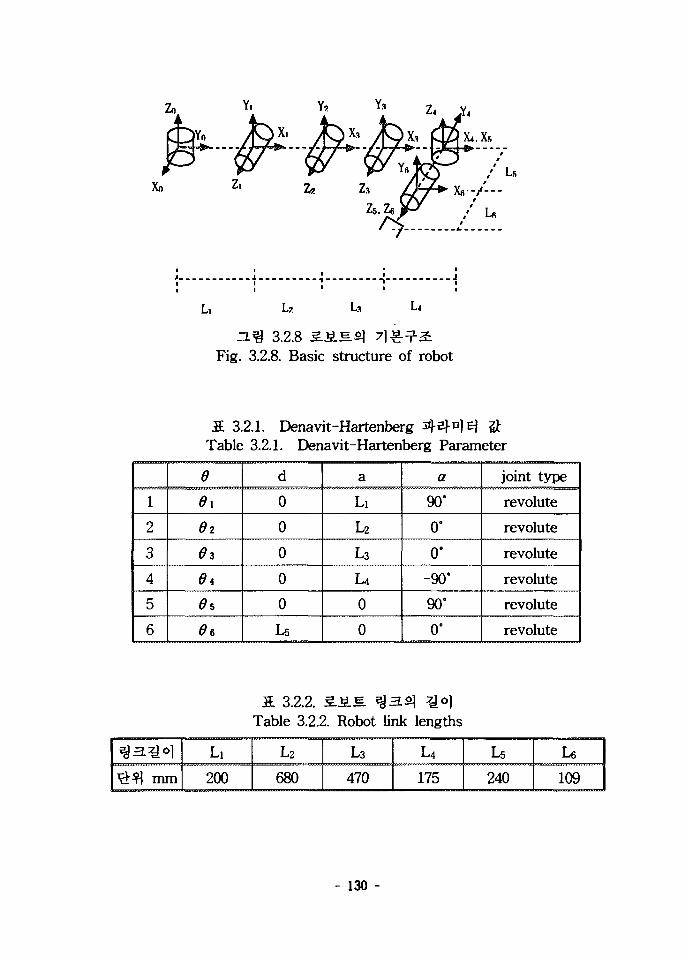
3.2.83J-
3.2.14
- 129 -
Lz Ls
3.2.8 3.J5LS. «|Fig. 3.2.8. Basic structure of robot
S. 3.2.1. Denavit-HartenbergTable 3.2.1. Denavit-Hartenberg Parameter
1
2
3
4
5
6
e0 i
02
03
04
05
06
d
0
0
0
0
0
u
a
Li
L2
L3
U0
0
a
90'
0°
0°
-90°
90°
0°
joint type
revolute
revolute
revolute
revolute
revolute
revolute
3. 3.2.2. S.S.E.Table 3.2.2. Robot link lengths
#fl mmLi
200
L2
680
L3
470
U175
U240
U109
- 130 -

Denavit-Hatenberg
71 =
71 =
T4 =
asi00
C3S300
C5S500
0010
0010
SI-a
00
-S3 0C3 00 10 0
S5-a
00
LL
LL
01001
\C\.iSl01
3<33S301
T\ =1 2
T3 —4
j5 _6 ~~
rc2S200
aS40
. 0
C6S60
. 0
~S2(200
00
- 10
-SSC600
0010
Z,2(
L2S201 .
-S4 L4aa00
00I0
L4S401
010
L51.
C1S6S234-C6S1S5 + C1C5C6C234 -aOBS234+5155SB-ClC5C2345BSlS6S234 + C5aBC234Sl -aS5SB-C6SlS234-C5C234SlSB
C234SB+C5CB5234 C6O34 - (3SBS2340 0
-C1C5 + C234S1S5S5S234
0
3
L,Sl + L2C2S[ + Z.3C23S1 + L4C234S1 - L5QCS + L5C234S1S5L2S2 + L3S23 + L45234 + L5S5S234
1
- 131 -
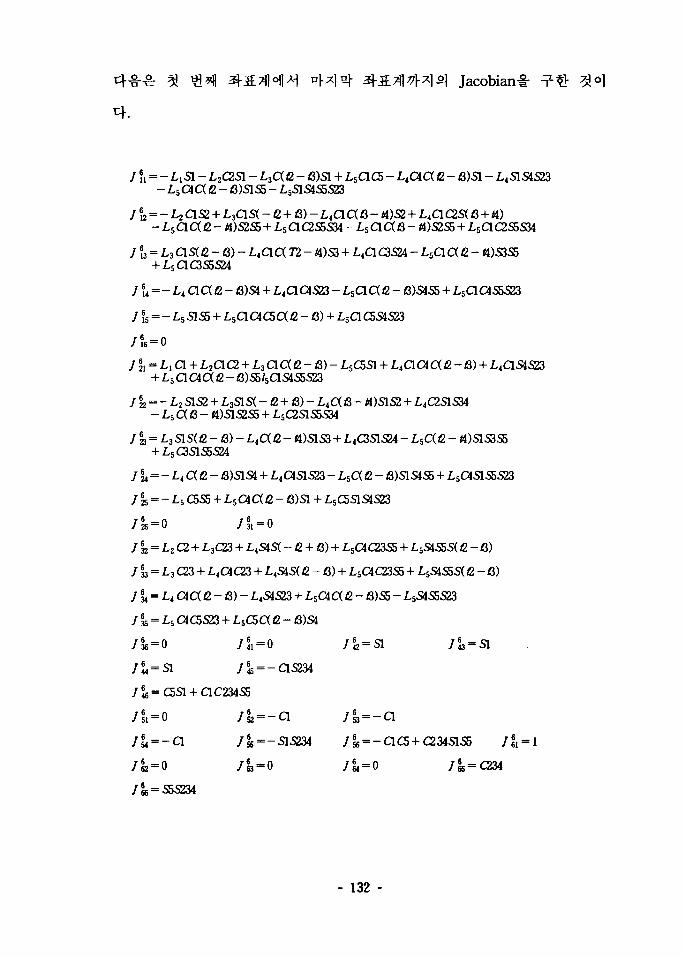
Jacobian-i-
— L : S I - L2asi- L3ae-Laaa fl)sss LS
3 4 4
- «)S2S5 + L5aC255S34 - L5QC(fl - «)S2S5 + L5aC2S5S34
- / 3 ) -+ L5aC3S5S24
5 = - L5 S1S5 + L5C1G1C5C( (2 - S) + L
, 2+L5 a a a e -= - L2S1S2 + L3SIS( - a + S) - L4aB - fl)SLS2 + L4C2SIS34
a )7 23 = -3 S1S(Q - & - L 4 a 2 - «)51S3 + L4C351S24 - L5C( fi - «)S1S3S5
+ L5C3S1S5S24
4C1S1S23 - L 5 a 12 - S)S1S4S5 + L5aS155S23
25 = -
7 32 = L2 C2 + L3C23 + LtS4S( - 2 + B) + L5aC23S5 + L5S455S( Q. - 8)
J % = L3 C23 + L4aC23 + LtSiS( Q - B) + L5CiC23S5 + LSSIS5S(, Q. - fi)
7 ?4 = L4 C 4 a C - 6) - L4S4S23 + L 5 C4a C - fl)55 - L5S1S5S23
71 ; = i - s « C5S23 + L 5 C5a fi - B)Si
— a 7s5 = -SlS234 7ss — QC5 + C234SIS5
- 132 -
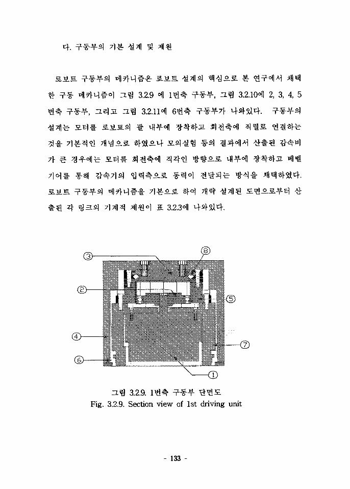
tb
7]-
3.2.9 ^
3.2.1H
3.2.10i 2, 3, 4, 5
3.2.9.Fig. 3.2.9. Section view of 1st driving unit
- 133 -

3.2.10. 2, 3, 4,Fig. 3.2.10. Section view of 2nd, 3rd, 4th, 5th driving unit
3.2.11.Fig. 3.3.11. Section view 6th driving unit
- 134 -

a 3.2.3.Table 3.2.3. Mass property of links
\
1
2
3
4
5
6
Pe(mm)
1794
1659
856
466
324
104
^ #(Kgf)
59.0
37.6
26.8
16
12.2
7.6
(m)
0.725
0.973
0.415
0.190
0.084
(-)0.085
(Kg.m2)
54.28
43.52
6.207
0.742
0.169
0.013
Radiusof
Gyration(m)
0.959
1.077
0.481
0.215
0.118
0.041
^ $(Kgf)
84
62.6
51.8
41
37.2
32.6
f^(m)
1.043
1.247
0.628
0.358
0.245
0.06
(Kg.m2)
134.7
112.3
24.53
6.171
2.793
0.283
Radiusof
Gyration(m)
1.266
1.339
0.688
0.388
0.274
0.093
SJSLJM
£-2-351
(1) SSS
- 135 -

3.7)] Newton-Euler^$ 4
22.^3 Newton-Euler^^^cf
Lagrange-Euler»9-^-ir
(2)
- 136 -
1=1 ?* (3.2.1)

3J11- M.#(interpolation)Sr
^ * l - f l ig-?>^(Linear Interpolation with parabolic blends)
di+v,4.
ai=q,{tk),
Ci2tb
Q,itk) + Qj
tkt<. tk+ltk+l
Vitk+1 + g,( tk) - g,( tk+l) + 2tb[ (dq t{ t k - j ) - vt]
(3.2.2)
3.2.12 ~ ZL% 3.2.14^
4-3-4
4-3-4
- 137 -

(3.2.3)
(3.2.4)
~ao, d2,
af,
C=
1
0000
14//,\2/i{
0000
0l - / f i
01
l/t200
00
— 2/A1
2/t2
21A0
00
— 2/*21
3/*26 / |0
0000
— 3//.6/*i
1
0000
-12/1- 1
(3.2.5)
- 138 -

3.2.12.Fig. 3.2.12. Joint angle path interpolation
3.2.13. 3 3 ^ 3 33.Fig. 3.2.13. Joint anglular velocity interpolation
na
3.2.14. ^ ^ z ^ - ^ S . ^ 3 3 .
Fig. 3.2.14. Joint anglular acceleration interpolation
- 139 -

(3)
£-3 , harmoinc drive
Simulation 1 :
Simulation 2 :
Simulation 3 :
A
margin^
3.3L 3.$)
3.2.16^: SJiS.
- 140 -

S. 3.2A. ^ l l re iH^ £ 4Table 3.2.4. Results of the simulation
• — — — _ _ _ _ _
Simulation 1
Simulation 2
Simulation 3
1 max
Tav
Tea
Nmax
Nav
Imax
Tav
Tea
•IN m a x
Nav
•1 m a x
Tav
T«,
Nmax
Nav
1 ^19
11.42
7.351000
533
24
138.2897
48035
12.2
6.9
1097361
2 #
573
428373
4160
1323
567
407
34222001190
581404
316
4080581
3 ^229
153
1082852
700
314
291
160625333
232177
143
31251060
4 ^
74
54
452500
1133
48
28
151196302
5943
33
1501889
5 ^
1.85
0.970.97
0
0
3.51
2.05
2.050
012.14.7
4.7
00
6 ^-
-
-
--
0.31
0.2
0.1827001440
--
-
-
-
3.2.15.Fig. 3.2.15. Assembled view of robot
- 141 -

3.2.16.Fig. 3.2.16. Outline drawing of Robot
- 142 -

4.
, q) + FV +FeKq) + G(q) + Td=i (3.2.6)
(3.2.7)
(3.2.8)
= q'lt)-q(t) (3.2.9)
(3.2.10)
^(3.2.5)1- 4^1
(3.2.11)
r) (3.2.12)
w=M~lra (3.2.13)
- 143 -

(3.2.14)
^(3.2.12)
(3.2.15)
computed
[Nonlinear inner loop
-& M(q)
NLinear system
Robot Arm
Outer loopfeedback
3.2.17. Computed S.SLEL *\}°\ 1-^- tFig. 3.2.17. Block diagram for computed torque
q.q
- 144 -

0.2 - 0.3
m/sec
kinematic
fe- PID
Ziegler-Nichols^i
3.2.184
DCS>
^ ^ 3.2.18. JointFig. 3.2.18. Block diagram for joint control
N :
J :
R : [Q]
E. [Kg.m2]
- 145 -

L : 5^3}
KT : SSL=
KE : W -
B : 3-^5
KP : Hi $ <
D : ^ 3 £
°J^€^ [H]
l ^ v ^ [N.m/A]
^•^r [V/rad-s"1]
^ [N.m]
< » 1 ^ K D
()
V(s) ~ (sL + R)(sJ + B) + KEKT
PID
= C1(s)0d(s) + C2(s)D(s)
+ Kps+Ki)KT
n(Ls2 + Rs)( )JLs4 + (JR + BL)J?+ (BR + KEKT + KdKT)s2 + KpKTs+ KdKT
- 146 -

5.
A.
Goertzsf Chatten^r «14-2-
« •
fe 4 «l^]a) LCD* #•& HMD (Head Mount Display),
flf}- 6 * H r £ ^ electromagnetic
3 -g- ^a
HMD*
- 147 -

3.2.19.
Fig. 3.2.19. Sketch of Virtual Reality System
Winey fe Argonne E-2 « f i
NASASl Arms Research Center <HMfe
Wright-Patterson Air Force Base Aerosj)ace Medical Research
Laboratory <^Hfe ^
- 148 -

7) F. Brooks
c»l controller)
tfl-g-O]
5d711
7}
- 149 -

Indigo2 4H T ^ W 1 } . °1 3 ^ 3 ^ 64
bit ^ ^ 1 R4400 CPU1: ^ ^ * n^3.^-(desktop) =LA^ *}±?iSL3.
24 H|E z
1248 X 1024^
*H(primitive object)
(1)
Toolkit Bl-ol «.
- 150 -
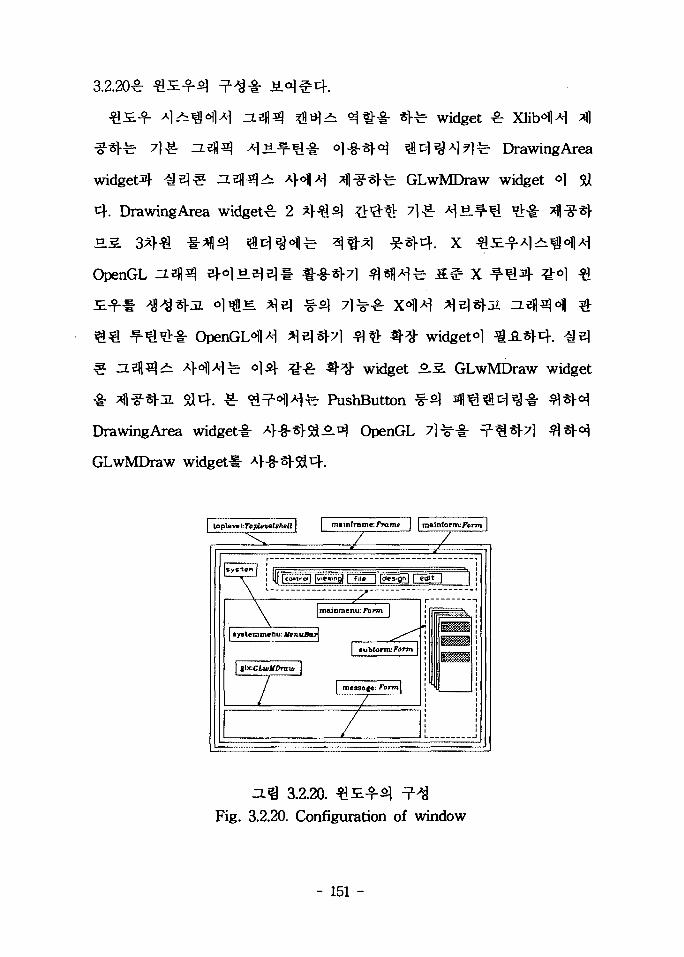
3.2.20£
widget^-
4 . DrawingArea widget^ 2
OpenGL
asfl^i
DrawingArea widget^-
GLwMDraw widget-i-
widget £
fe. DrawingArea
GLwMDraw widget *1 5U
f. X
x
widget^l
widget SLS. GLwMDraw widget
PushButton
A ^ OpenGL
loplevel-.TopUvelshstl I | mainframe: Frame j j malnfornv/'orru I
! l|| |conir-oi| |vie»mQ| |~fi i f~l Idesign] | editI
mainmenu: Form
systemmenu: tfenuBari
subfornv Form
1
3.2.20.Fig. 3.2.20. Configuration of window
- 151 -

(2)
(71-) 2 ^ 3 21-3]
cfl^-l-(component)
(SoUd, Wireframe) % ^%$ v]^^^o] ^^( 7}
Boolean ^^(Union, Common, Substract)^
^^-^(assembly)
^ ^ r 71 ^
21- : 2 ^ 3 £15] >d| - >a^ gj 7H2(visibiUty)
- File 2 1 - :
- 152 -

- Place S.f- :
fe 3-D geometric modeling
- wireframe modeling
- surface modeling
(D polygonal representation
(2) parametric representation sculptured surface)
- solid modeling
• wireframe modeling
2-D 3h& 3-D -&^1« ^ £ 3 %n&^2. M- flfe ^
ty$± 7\% #£?>}A #^J11- q-^iflfe ^'goiq-, 3-D
• surface modeling
°] 3-D geometric modeling ^ ^ - S - 3.7$ polygonal representation
- 153 -

parametric representation-5-3-
polygonal representation : <=>1
polygon^- °l-g-*M **I|S] a ^ - i - H-EhlM 3*}
parametric representation or sculptured surface
representation : «1
B-spUne, Bezier
curve, cubic-spline-^J1)- ^ ^ r parametric curvesM- surfaces
solid modeling
solid primitives* 6l-8-*M
B-rep(representation) :
B-rep^8: solid object^ ^ ^ 1 S T 2 -^* ! -^ faces, edges,
and vertices!- °l^-«>^ - i - ^ 1 * M - ^ H E 4 .
CSG(constructive solid geometry),
CSG 7 l^^ r solid primitives^ Boolean operational ^
sweeping
sweeping^ ^ ^ ^•'H^l ^ S . # tyty point, curve or
- 154 -

surface
5.JSLS*
(assemble)sM
(Wire)
- 155 -
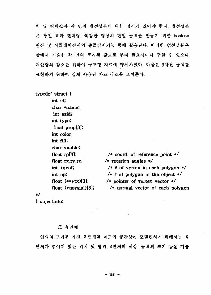
A
boolean
typedef struct {int id;char *name;int asid;
int type;float prop[3];
int color;int fill,"char visible;float rp[3],"float rx,ry,rz;int *nvof;int np;float (**vtx)[3];float (*normal)[3l;
*/} objectinfo;
/* coord, of reference point *//* rotation angles */
/* # of vertex in each polygon *//* # of polygon in the object *//* pointer of vertex vector */
/* normal vector of each polygon
- 156 -

"Display" 7)
"Palce"
71-3., , y, z)
71
A x, y, z 6.S
(y/2 > -MIS. >-y/2), (z
(x/2 > 71-3.
0)
7l^H7l(m , feet, inch, cm, mm)
4.
n x 3
"Control"
n
35
- 157 -

n
-51} ^ £ 3 o>^4 4 ^ 3 2
x n 7fl3 3 4 ^ ^.^-4 o}efl «.«. - s.^^€>7l ^ 2
4 )^ S M ^ 1 4 x n
"Control"
4. r SAS. £ M ^ ^ 3
>^ n 7fl3 -a- fl-S-S. i«^*|-5a4. °13 £ £ " ^ ^ S .2.
3 3 ^ * n o]2} *|-3 t ^21 r r n x ( n/2 +1) 7V
(4) Boolean
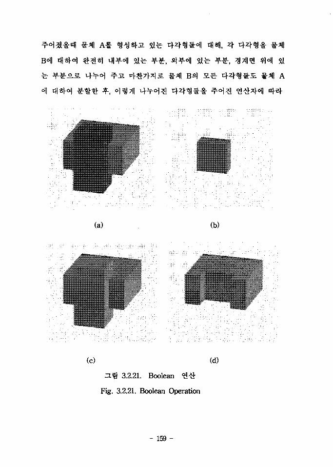
3.2.21 - ^13 ^ ^ boolean 3 # # iL^^3L 5U4. ^ ^ 3.2.213
(a)3 Q°] #^1 A3 **« B,
- 158 -
tun.
(a) (b)
(c) (d)
ZL% 3.2.21. Boolean <3#
Fig. 3.2.21. Boolean Operation
- 159 -

Boolean
3.2.21
3.2.22^
*
(dHr
3.2.22. Boolean
Fig. 3.2.22. Flow chart of Boolean Operation
- 160 -

B*\ s.^ 4 4 ^ 1
A5]
«• e]iE
B7>
Bl-
B7>
A,
37M
- 161 -

. 574
4.
- 162 -
5U4. o] ^ i L # s^} Ai^-5] P§^1 Bflfil §^6( 7 ^ 2 584.7)-,

$i4.
^4.
"assemble"
LasidH
- 163 -

rfl
Silo] A i ^
o.
link) %
«: r 584.
link)#
4
- 164 -

(3)
. Workcell
S.&E. ^fill- fl^ ^^-^(External Axis)
workcell^i
- 165 -

(4) 3 ^(External Axis)
typedef struct {char *comp",int jnt;struct component *extcomp;
} extjntinfo;
5a
4f. ^ 6
S A ^ 2 7fl *l3l^£ *fe ^ ^ #
i f C i wokrcelM- ^^ t j - j l T 1 ^ * B 3 2 Si^ ^ ^ ^ *><H S.S.
. c 7> 5.J5LE. End
6 ^ 3°fl 2
^ (a t t ach )
. ^ S-iLS. End effectoHl
7}
- 166 -

4. ##^^i 71 a
S-JiM-g- <>l-8-*M ^ ^ ^ ^ f l ^ l fl«fl>Mfe on-Hne^-
On-Une
3 4:7} 21
.7\?\7\
CimStation^l ^ e | A>-§-S1J7 ^[cf. o]
i
- 167 -

fe O]
7JIAJ.aJ.7l
(1)
3-8AH
line 2
3.2.23. -^
Fig. 3.2.23. Minimum distance between two straight lines
- 168 -

fe 4-8-4
( 1 - = o
= 0
input :
l : point A -
point B -
2 : point C -
point D =
(Xu, X2A, X3A)
( XlB. X2s, X3B )
(Xlc. X2c, XZc)
(Xu, X2D, X3D)
- 169 -
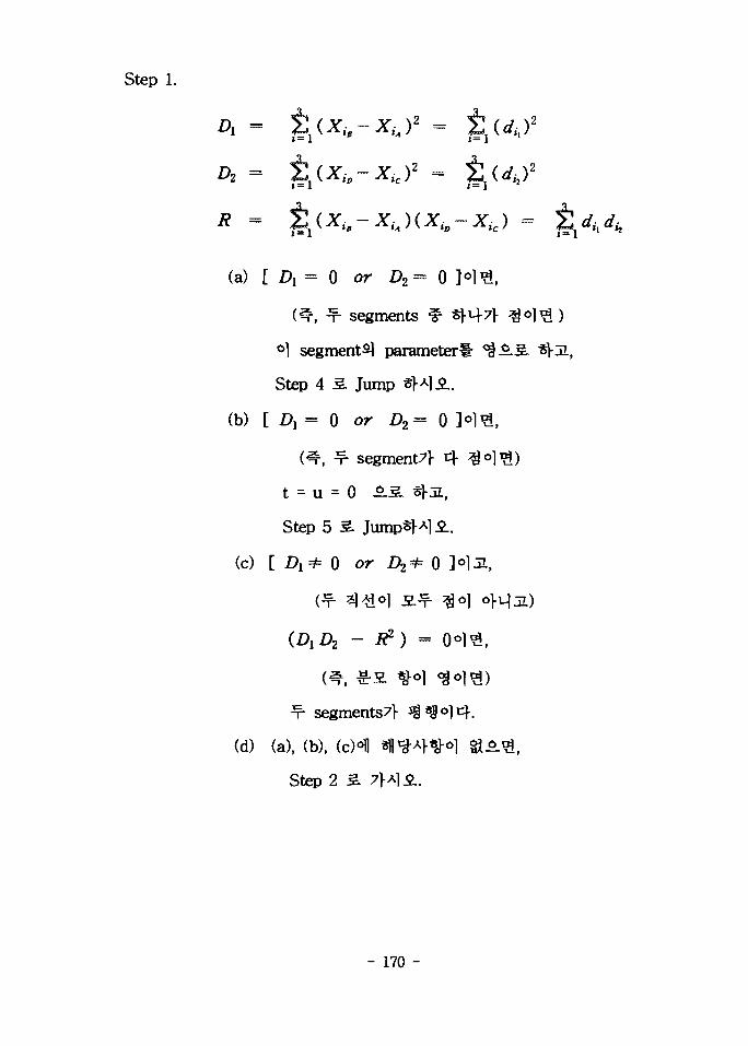
Step 1.
A =
A = %{Xh-Xicf -
(a) [ A = 0 or A = 0
m-, -f- segments ^
°] segment i parameter
Step 4 S. Jump 3M.2..
(b) [ A = 0 or A = 0 ]
m, ^ segment7]- 4
t - u = 0 -5.
Step 5 3.
(c) [ A ^ 0 or A * 0
(A A
f- segments7l-
(d) (a), (b),
Step 2
- 170 -
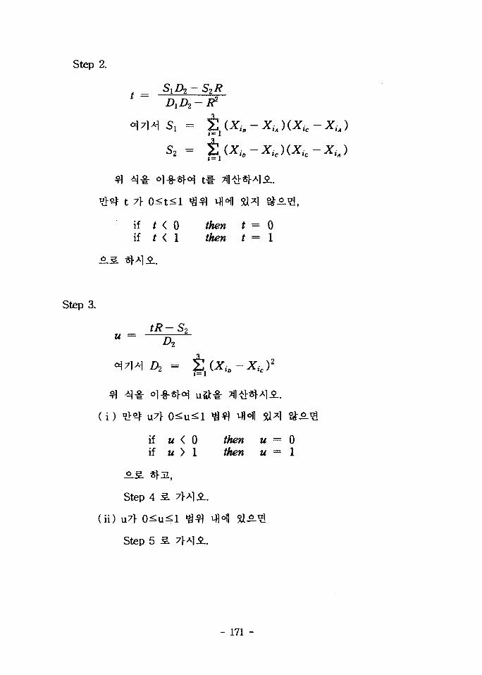
Step 2.
°\7
t 7}
ifif
AA-H Si =
S2 =
0<t< l $
f < 0f < 1
i(
t * ^1
11 $J
tt
~xic
M l
1*1 &-
= 0= 1
Step 3.
A
( i i )
Step
U7> C
Step
ol-§-§H
if a (if u >
4 5 . 7}>*
5 sL 7}*
01
.1*.
•1-5-.
M = 0M = 1
- 171 -
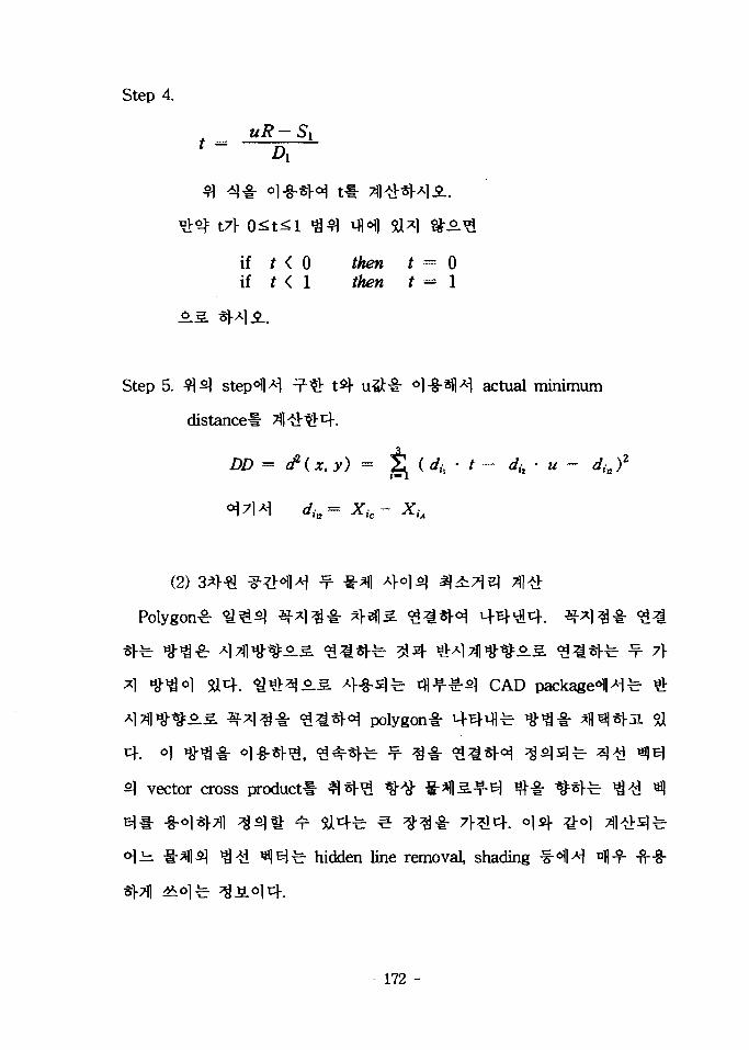
Step 4.
if f < 0 to f = 0if t < 1 f/^« ^ = 1
Step 5. ^ ^ step^l^ ^Q tty u&-& o]&m] actual minimum
distance!- ^
DD =
Xic- XiA
(2)
A "%"&<>] 5U4. ^ t i t ^ ^ - S 4-8-slfe ^ ^ ^ - ^ CAD packaged4fe #
polygon^-
vector cross product*
r
hidden line removal, shading ^ H nj-f -ft-8-
172 -

3.2.24^1^i
polygon6!
convex polygon^:
3.2.24. Convex
Fig. 3.2.24. Convex polygon
o]6\] 3.2.25°])^
polygon^
concave polygon^
3.2.25. Concave
Fig. 3.2.25. Concave polygon
- 173 -

convex polygon^}- concave polygon ^fl^-g- polygon •§• °]^-*)-(^ -2-
3 * } ^ £•*( 3 . ^-#sM3, convex object^ <$$$ ^ ^ 4 *<}•>£ 1- o]
ll concave object^
3.2.26«fl>H
. o]
Polygon 1
3.2.26. ^
Fig. 3.2.26. Minimum distance between two planes
- 174 -

( P - Q ) • ^ 3 is) ^-tf^ef = 0
( 1 - 1 ) • ^ 2^ H#**)Ei = 0
polygon *\°}2\ tt^Qo] 5- polygon
371 # £fe ^ polygon
r polygon^ S)^| e ^ ^ l f e convex and/or concave
«1^ global ^ ^ T l s l l - 0
Polygon-!- ol^-sV^ ^^1
polygonal ^-fi.S}4. # ^ l « e4*)-7l ^t!- polygon^
polygon 4 o l i | ^ i T l e l l - <»l .fe. ;g-§-
Polygon^ 1*11 5-A> s l 0 ! ^ convex object ^ convex object
71 ell- ol^Rr ^6.5.51 ^ e ^ l a . ^ i l s .S . &£•
Convex object 4 convex object
- 175 -
3E concave o b j e c t ^ global
t\ z\v]^5L y? #i(l|A>o]sl -rfl fl^|6|| i4e). global %
%SL3. ^ 5 - ^ - .SL=8-*M ^fetf. n ^ H S convex objects ^H 6 ! !^ S.
^ - ^ ^ . S global ^ i ^ e l l - 7H#sKr£fl o ] ^ . ^ ^ . j , . ^ ^ ^ . c o n c a v e
objectsfe aj-8-^- ^ Sicf. Polygon^] $]*% M-^-^^l concave object*
- convex polygon-!:
A polygon^ ^ ^ - i : 7\A^, ^ polygon £ £ ^
A]a 3*1*1 &^, polygonal
• zj- w|fil normal vector
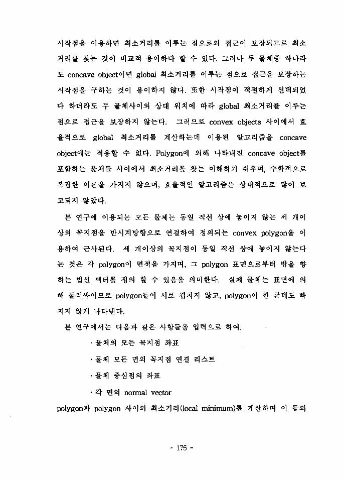
polygon^ polygon 4°1^1 ^ ^ ^ e ] (local minimum)!- 3l#SM °1
- 176 -
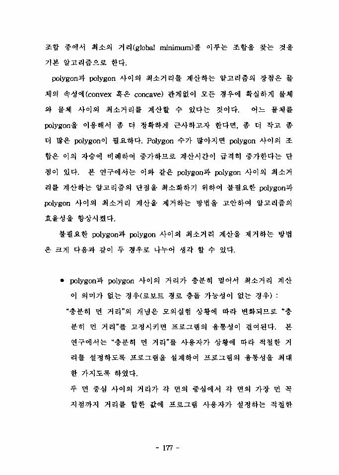
3 ^ 1 7 E] (global minimum)* °l^Hr atf-g- #-&
polygon^)- polygon
4?qo))(convex ^ ^ - concave) #
polygon!- ol-8-^^i # c]
polygon*] ^ . 8 . ^ 4 . Polygon ^7> S°>^]^ polygon
polygon4 polygon
polygon
polygon^ polygon
polygon^- polygon
el l -
- 177 -
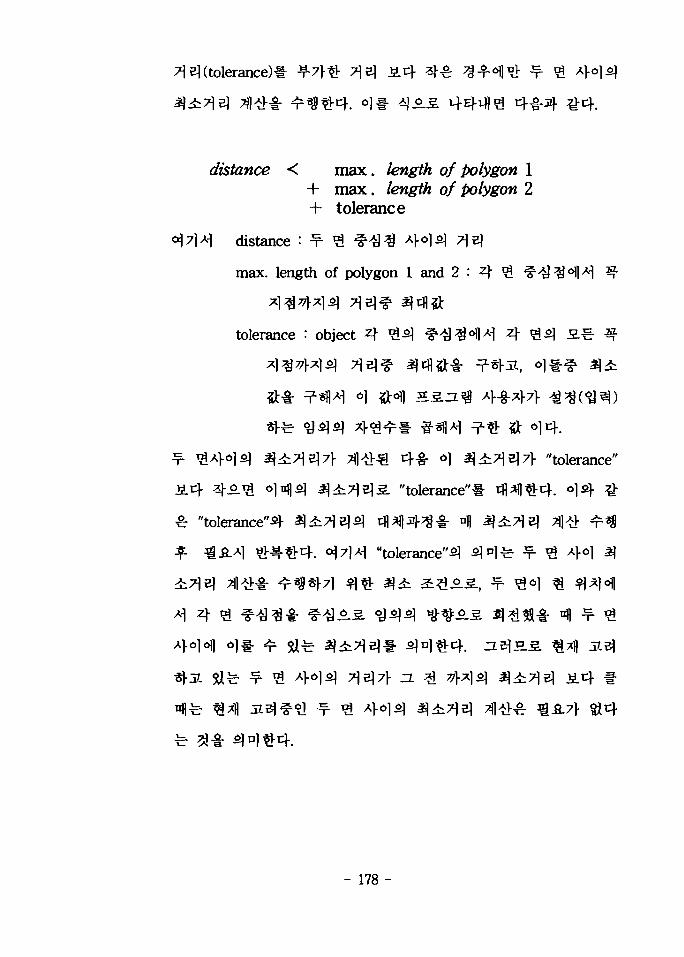
^( tolerance)*
distance < max. fewijtfft of Polygon 1+ max. /e«gt/& 0/ Polygon 2+ tolerance
distance : -r- ^
max. length of polygon 1 and 2 :
tolerance : object A ^ ^ ^ ^ ^ ^ ^ I 4 ^ ^ -£€-
"tolerance"
"tolerance"« tfl^lth^. o]i)- 7k
"tolerance"^ $±7]?)<>\ rfl^)4^^- nj) ^
"tolerance"^ ^nl
- 178 -

polygon-4 polygon * H ^ ^^)S.^-B\ ^4:^e | (global minimum)
f| A>oi^ ^ ^ T 1 e) (global minimum)^
normal vector 4 O 1 ^ dot product7]-
operation) 7 l ^ S } ^^^oflA^ ^ t f l ^ l ^ ^
^ 7 ] ^ ^ normal vector * H 3 dot product7>
W8 ?!)£} 3:1
(-)O)4. =LZ]l
fi2^\- vector
f^r ^- H- normal vector A}°\'
4 ( W2 ^ ^ »3 ^ ) ^ ^ ^ " ^
f j ^ dot product7> <g=(+)o]u}i
normal vector n%Q vector
isms («2 ^ 4 «, «W ^
5a^-4, ( n4 « 4 W8 ^)5] £
2} dot product7> -g-
A1fe normal vector
, ( «4 ^ 4 - «8 ^ )
v4^- dot product7]-
- 179 -
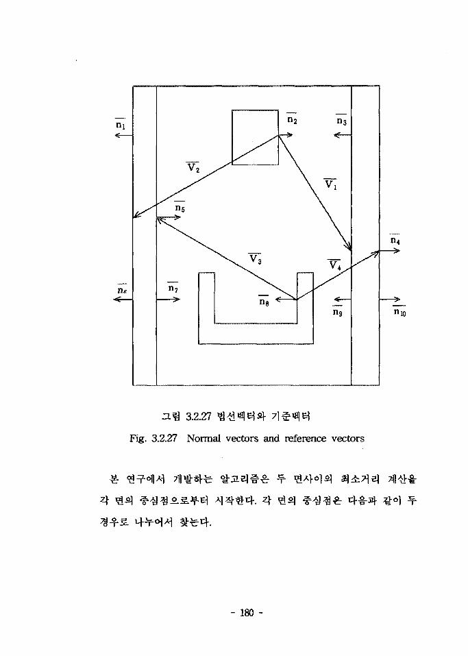
3.2.27
Fig. 3.2.27 Normal vectors and reference vectors
- 180 -

I) 4 7fls} 3**1 $ 0 . 3 . ^ € polygon^ 3-f (#z\% polygon)
2
2
2
» *
- , z
$•3. = (*<>. y
2
yo+3w2
2
=(*2 . to. *z
= (x. y, z)
H) m 71] o]^-^ ^ i ^ o . s ^ - y ^ polygon^
x ~
y =
z ~
- 181 -
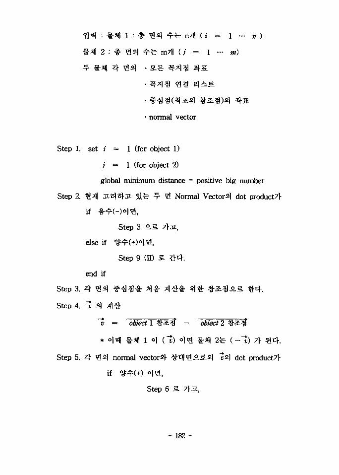
2 : $• g £ | ^ fe m7fl (/ = 1 - m)
4
• normal vector
Step 1. set i — 1 (for object 1)
; = 1 (for object 2)
global minimum distance = positive big number
Step 2. H4 a i ^ t r a ! & ^ ^ # Normal Vector^ dot product7l-
if **H-)*lfc,
Step 3 5.S. 7>JL,
else if <a:ir(+)ol^,
Step 9 (ID 3. def-
end if
Step 3. 4
Step 4. "t
"y = object 1 # 2 ^ - o#ert 2
* «>H #^1 i c] (-J) 6)^ i- j) 2fe
Step 5. 4 ^ normal vector^)- ^ t f l ^ ^ . s . ^ 1s\ dot product7>
if **^(+) 6 1 ^ ,
Step 6 S. 7}3L,
- 182 -

else if ,
Step 9 (II) 3,
end if
Step 6. «*fl ^ iS
tmp_dist -
- <¥ ^ ^ 3 4 A
if (tmp_dist) < (tolerance) °1^ ,
Step 7 3. 7>JL,
else if (tmp_dist) ^ (tolerance)
Step 9 (II) 3.
end if
Step 7. ^<^M1 4^8-a- U J 4
I) 4 ^6j)A-l vector 1
y = object i
* -S-lfl^oi^fe - 1 71-
H) ^ ^<^14 search direction
s = v — \v n) n
* 1 # normalize
* n •& polygon^ normal vector
ID) search direction, 1 1 Kuhn-Tucker condition
if ¥ ^«H)4 II 5»2 = 0 <>1<S,
2) Step 9 (I) 3. ?>tf.
- 183 -

else
1) ^ search direction
2) Step 83.
end if
Step 8. (I) search direction^
(1) ¥ %&%*]
1) SN % S ^ # ^14fe search direction, s
2) 4 ^ ^ofl oj^. search direction,
4 .
(2) t l ^-£
1) ^-S^o) edge°11 ¥°lfe ^<>1|^t- °] edgel-
-I: T f!: search direction-5-5.
2) tftmgaiH search direction^:
a)
b)
c) ol^ol ^-cfl^i f-<8€ -fr ^14^ f-^€ edge
- 184 -
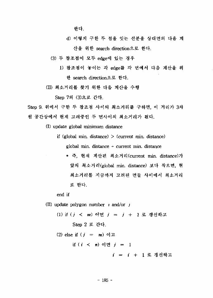
d)
#-§• $)$: search
(3) ^ #2:3W S ^ edge fl fl
1) ^-^^^1 ¥°lfe 4 edgel- 4 ^^1^1 4-g-
tb search direetion-S.3.
(H) ^4i^Ell- #71 3 $ 4-8- Ti
Step 7^ (3) 6.S ?>4.
Step 9. fl«H ^ ^ ^ # 2 : ^ 4 ° 1 ^ ^ i T l ^ l - ^^V^, o] 7 Hi7> 3*}
(I) update global minimum distance
if (global min. distance) > (current min. distance)
global min. distance = current min. distance
* ^ , ^ ^ %}QQ 2}4:7ie)(current min. distance)7r
7]s](global min. distance) J£tf *t°.&, ^
^ 1 : A>o|o]lA^ 3
end if
(II) update polygon number / and/or ;
(1) if (j < nt) °)^L i = j +
Step 2 3. ?>cf.
(2) else if ( ; = m) °)IL
if (i < n) o ] ^ ; = i
- 185 -
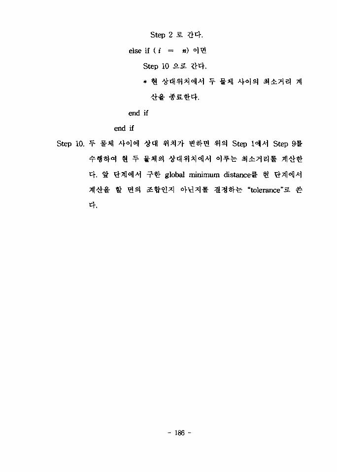
Step 2 3.
else if ( i - n)
Step 10 £.3.
end if
end if
Step 10. ^ »*|| ^l0!6!) ^ ^ *f\*\7\ ^§1-^ ^5] Step H>H Step 9
global minimum distanced %
-fe "tolerance"^.
- 186 -
6.
technology)
i^XHuman operator)^
, Slave manipulator)^
fe A12J-, $zj- f
(Input device)7> -S .^€4 . °)z\& <im%Z\^ ^ 4 1 (Master
manipulator) £•&, ^S.^-mi-e1(Handcontroller)Hl-
- 187 -

ifl-g-g-
71
^#<HM(Stweart platform)^ ^ »i
7)
(Replica type)3|- ^ - § - ^ (Non-replica type or Universal type)-S-S.
1:1
3 W(Joint-to-joint space control).
7|7>
- ^tWCartesian space
control).
Joint-to-joint
188

4.
• Cartesian reference framef*
I I S . 1-JE.S.
717114
1980
- 189 -
-g-o]
Cartesian control^
A
- 190 -

(Transparency)* £7\)?>}7)
of Telepresence)*
Transparency
Transparency
Transparency*
-i7||
JEfil Decoupling.
- 191 -

71
7>^(backdrivable)*
safe
- 192 -

(1)
£ ^ (Decoupling)^ 6^-fi-S.
i?lS(Wrist joint)S] Yaw,
Pitch, Roll A ^ l r £ : Gimbal
3.2.29^
DC
4.
^i^-Sr^-i- *l-fe- 1 Si^ ^(Z # ) ^ -Tflfe ^ I-(Counterweight)^
^5-^(Counterbalancing)* olf-Sfli^,
^^H-^r ^^#(Counterweight)4
l ^ ^ ) 3L
- 193 -

3.2.28. ^l
Fig. 3.2.28. Schematic of serial link handcontroller
J f l S H * 4s
- 194 -
Pitch
Yaw
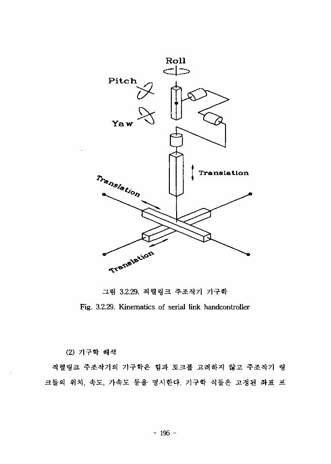
3.2.29. ^%*%3.
Fig. 3.2.29. Kinematics of serial link handcontroller
(2)
- 195 -

3 3 tfl^o] l}-g-o|H
1 = 1,2,3)7}-
{2} {3}
(7J-)
Denavit-Hatenberg(D-H)
3.2.30^8:
4 . ZL^ 3.2.30^:
Q, 6 =0, 05= /2
^efl<y {0}£ ci-0 ^ n
(0), {1}
e ^ (2 , 3, 4, 5, 6)1-21
3.2.5^ ^ 3 : ^ 7 1 ^ D - H ^
a, . , , a , . , , rf,-, ^.fe AA ^3. length, ^ 3 . twist, 3:?]^. offset,
angle* ^ - E } ^ ^ , L3
3. 3.2.5. D-H £^r
Table 3.2.5. D-H paramerters
i123456
0-x/2n/20
ff/2
-n/2
ail
000000
di
di
d2
L3+d3
U00
0i0
n/20<^05
06
- 196 -

3.2.30. 1
Fig. 3.2.30. Coordinate assignment of serial link handcontroller
- 197 -

matrix)!-^- ^(3.2.16)4 ^<^|
(Transformation
2 r _3 1 ~
?T =
1 0 00 0 - 10 1 00 0 0
1—1
000
0100
0010
010d\1.
0-L3 - ,
01
iT = 0 0
o5 o 5
0 0- 1 00 00 1
,= cos(
IT =
IT =
5 r _6 -* ~
i=l,2...6
0 - 1 0 00 0 1 d2
- 1 0 0 00 0 0 1
c4 ~s4 0 0S4 C4 0 00 0 1 L4
. 0 0 0 1
0 0$6 C60 0
0 0- 1 00 00 U
(3.2.16)
(3.2.17)51
l i S.$<£ {OH S^°J {6}^
IT =55 CR
— C4 C5 C6 —0
"4 $6
S4 *6
— Si C 5 S 6
C 4 C5 SR-
0
~ C4
- stSi S5
~ C4 S50
L3 + L4 +
&\1
(3.2.17)
- 198 -

(0}°fl ^ 4] (3.2.18)4
Op 0 T 6pHandgrip 6 J r Handgrip
6 p
rp,Handgrip
L 3 + L 4 + fl?3d2
(3.2.18)
of
i= 1,2.3).
(3.2.19)^
Handgrip
(3.2.19)
r2Z r23
(3.2.20)4
- 199 -
d2 = Py
d3 — px — L$ — L +
di = AtarQ.(si, c.) for z = 4,5,6,
= - r1 3 ,
vl „ 2 r ~ r 1 2«5 ' " S5
(3.2.20)
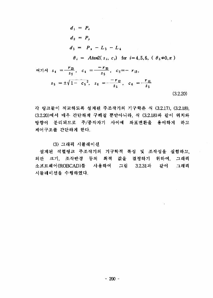
g. ^ (3.2.17), (3.2.18),(3.2.18)4 ^o ) ^
3.2.314
- 200 -

3.2.31.
Fig. 3.2.31. Graphic simulation of serial link handcontroller
- 201 -

7<H3, 3^$ , 3^5. ^2Ul *fl*M -fro^-fr
. #^«(Stweart platform)^
71
^ 3 - ^ (counter
balancing)^ ^*S-H 4 ^ sfl^* ^rfe SiAi4 ^ ^ ^ - 7 l ^ ^ 5 - ^ ^ ^ l ^
71
7V
^ 4 . 2: 71^7)- ,
- 202 -

effector) 3 3
5U4. ^ ^ ^ - ^
3.2.32<H1
^^-g-7) (prismatic joinOS-H ^ - ^ 4 ^>^r 4 ° )
1 6-6
«f^:(base platform)i
- 203 -

4.
(1)
(7r)
A A
3.2.334
Basev
(a) General type
(T) Prismatic Joint©Hook Joint(3) Spherical Joint
(b) Merlet type
3.2.32. a ^ l m
Fig. 3.2.32. Comparison of joint alignment.
- 204 -
B4 B3
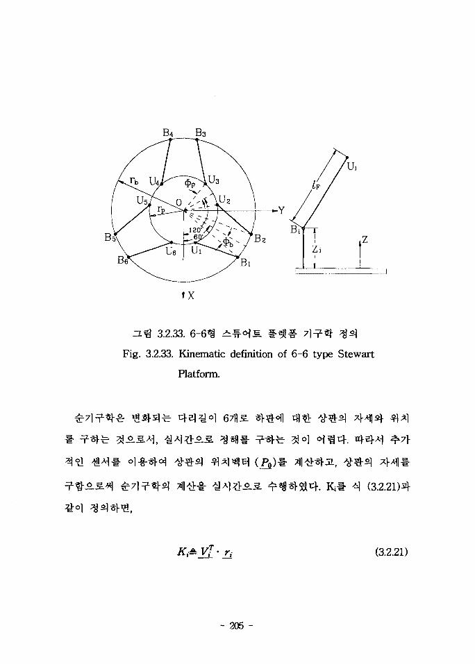
3.2.33. 6-
Fig. 3.2.33. Kinematic definition of 6-6 type Stewart
Platform.
^Jo] oj^cf. n)-5H
(3.2.21)4
(3.2.21)
- 205 -

3.2.34.
Fig. 3.2.34. Kinematic configuration.
(3.2.22m
= U«Vj • JJ + UiyVj • (3.2.22)
Viysy+ Vu
- 206 -
\K,
K4
an •••
nx
ny
sx
(3.2.23)
^UixVu , a&= UaViy ,^UtVi, , a6=UiyViy,
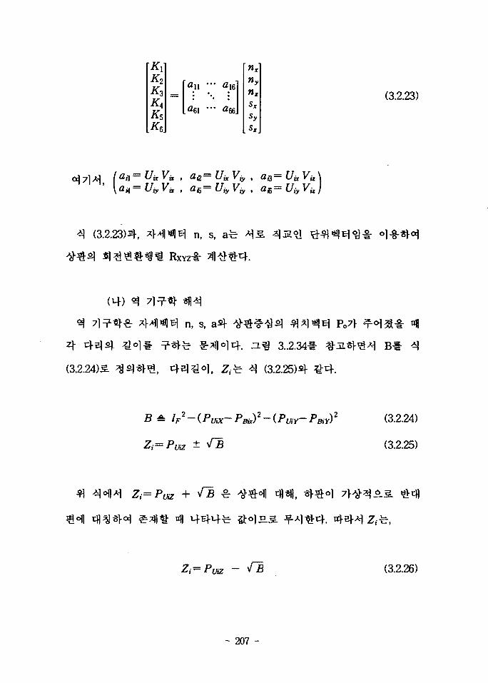
(3.2.23)4, n, s, afe
(14)
(3.2.24)S
n , S,
3..2.34
^ q (3.2.25)4
po7}-
A IF2-(Pax- Pay)2 (3.2.24)
(3.2.25)
(3.2.26)
- 207 -
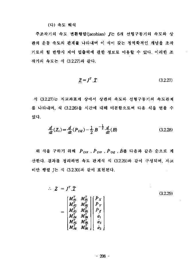
(3.2.27)4
5^4.
(3.2.27)
(3.2.27)fe
df
(3.2.26)-!-
dt{2 (3.2.28)
(3.2.30)4
(3.2.29)4
MTM
MaMA3
MTM
M%,MM
MTm
MTm
MTm
Ml*MisMis .
\Px]PY
Pz<*i
a2
(3.2.29)
- 208 -

[Zlt Z2, Z3, Z4, Z5, £ 6 ] r : 6711
[ Px, PY, PZ, ax, a2, az]T : end-effector^
MAI MA2 MAZ MM MAS, MAS
MB\ Mgi MB3 M& Mfc Mg&
^ el (Twist)
(3.2.30)
. 2
(fori=l.-,6)
- 1
2 M23)
(fori=l,-,6)
= — S2 C3f/i(+ Si C2CzU
= -C 2 S 3 ^ - (S 1 S 2 S3
= (Ci S2S3 — 5i C3) £4,
z==~ S2S2 Ua + Si C2S3 f/
- 2PBiXPuiX-2PBiYPuiY)
- 209 -
(3.2.30)«»ll W£2) « el (principle of virtual work)!
^ safe^l, °lfe 4 (3.2.31)31-
(3.2.31)
M=[i, mV : end-effector^l ^ ^EKwrench)
3.2.35-H1
^(singularity)*!-
- 210 -
(2)
Merlet^ ^ ^ ^ ^ . 1-^f-^r 71^-

3.2.35.
Fig. 3.2.35. Design parameter
7]=?7} ?- #o|3(singular paint) 4
a]- (Dexterity Index, DI)^
°1 jej- sj-ig jfi] z^ 1 (column)^,
-id
- 211 -

(3.2.32)**
-SOI -S06.
(3.2.32)
A *
A±JTAJ (3.2.33)
(3.2.34)4
(3.2.34)
JL-fh^(eigenvalue) . V * °l-g-*r
(3.2.35)
^(reciprocal)?] ^-Tfl^^ ^l^j(basis)*
(3.2.36)4
- 212 -

^ f l (modified singular value decomposition)-^ °]-8-^r°i J
7} ^o]^ *]£. %+t j ^ A| (3.2.37)4 ^ol *««« ^ 5114.
/ = £/Vr (3.2.37)
4*1 ^ (3.2.38)4 ^-o) 1 4 ^ ^ ^ ^ 4 .
^ [ i / j lC /z ]^ 3 " (3.2.38)
(3.2.33)4 (3.2.34)5. -¥-^ / r A / =
(3.2.39)
(3.2.40)4 Qo] ^ ^ ^ ^ 4 . °1 n A ^ °^^ tb^ (positive definite)
DI * IdU (3.2.40)
- 213 -

go] 7^.3.
3.2.36(a)4 0.591
(a)
3.2.36(b)).
« •
rpdb
(b)
3.2.36. D.I3 ^<^1
Fig. 3.2.36. Tendency of D.I
- 214 -
IO 1.5 t o ' ' :>o - i s - 1 0 -06 0.0 O.B 10 1.& t O
(a) rp/rb ( b )
4.0 '- —
.0 -1 ft -1
/
(/
//
f
/*
v i i /
^ M
|!
r
3.0
1 5
~/^~
/
i1 * \Jr/
\
(c) Z^i/rb (d) lF/rh
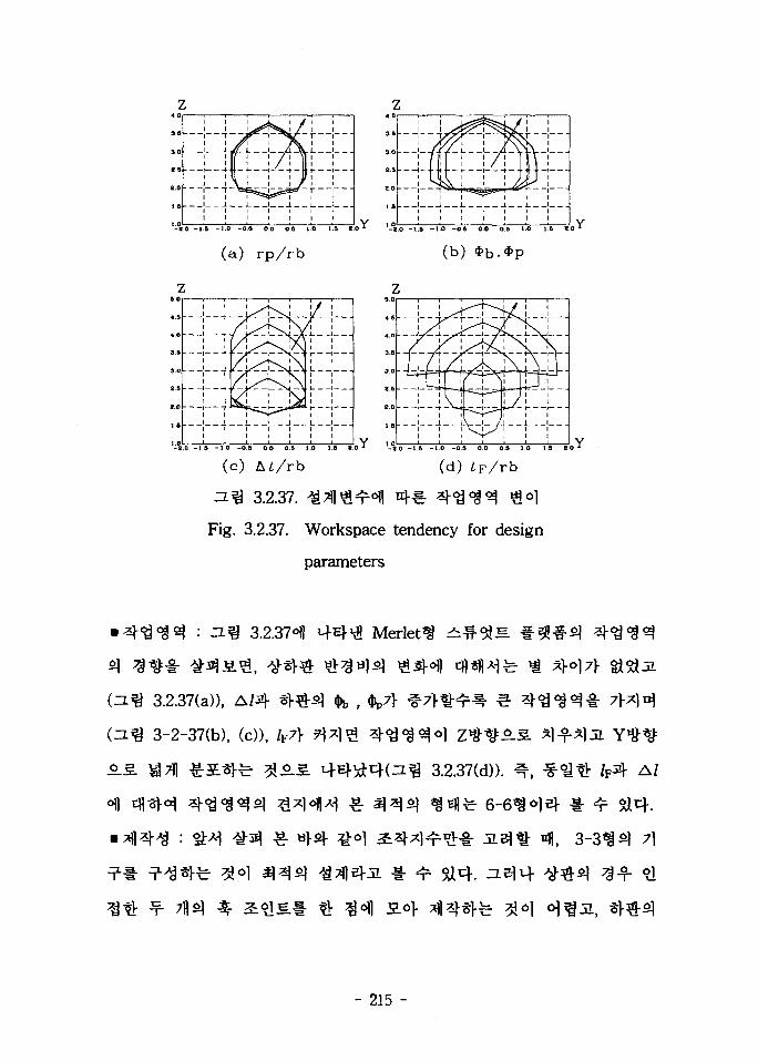
=L^ 3.2.37. ^Tfl^ofl 4 1 - ^ ^ ^ ^ ^°1
Fig. 3.2.37. Workspace tendency for design
parameters
3.2.37- 1
3.2.37(a»,
3-2-37(b), (c))t
3.2.37(d)). ^ A/
7}
- 215 -

4. ° l i l * *fl*H£s) <H3-§-§- # # * M , ^ ^ ^ H M 3 3 ^ $#?! 6-6
(3)
3.2.38)2? ^ ^
baU bushing )•§• J L ^ ^ « ^ 1 ( flange
- 216 -

jfe- .•
3.2.38.
Fig. 3.2.38. Assembled hand controller

0° 41
10° 3. ^ « B 5 l 4 . # # aV , rp$)
0.57}
10* s.
-2.El41
3-71
- 218 -
223.6imS.,
^ § f ^ 4 . *>]«!«- 7 l^ -^^?
3.2.39S)-

213 mm
(a)
X(b)
155 mm
3.2.39.
Fig. 3.2.39. 3-D plot of workspace
- 219 -

S. 3.2.6. ^2:3-712] A]
Table 3.2.6. Comparison of design parameters between prototype and
rebuilt prototype
rj(mm)
r^(mm)
<t>b, ^ ( d e g )
IF (mm)
zJ/(mm)
70
29
20
182
100
2.40XNT3
110
55
10
224
155
4.99xlO"3
joint)5+
joint ) ^
iMspherical
3.2.40^
- 220 -

set screw
-shaft
bearingsnap ring
universal joint
3.2.40. Spherical 3:?lKFig. 3.2.40. Design of Spherical Joint
- 221 -

Base Plate
Ball Bushing Unit
Shaft
Wire Tension Unit
Motor
2a
Pulley
Wire
Pulley
3.2.41.
Fig. 3.2.41. Design of Linear Actuator using Wire
Mechanism.
3.2.420)] ^
- 222 -
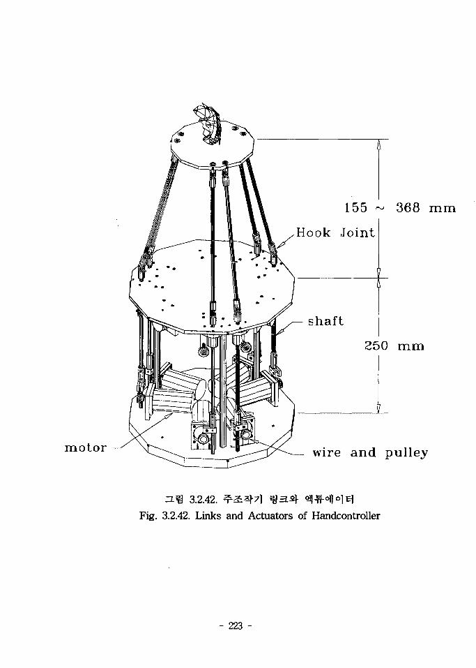
motor
155 ~ 368 mm
Hook Joint
shaft
250 mm
wire and pulley
3.2.42.
Fig. 3.2.42. Links and Actuators of Handcontroller
- 223 -
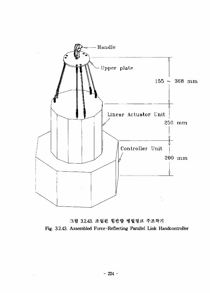
Handle
Upper plate
155 ~ 368 mm
Linear Actuator Unit
250 mm
Controller Unit
200 m m
3.2.43.Fig. 3.2.43. Assembled Force-Reflecting Parallel Link Handcontroller
- 224 -
cf.
^371
- 22R -

75cm, So l 25cm
8m
8051^- ifl^4<d^- ^ 5962R9563801QQX1- 1
cf^^(redundancy)s)- 4€-
fe ^t^-(divergency)
- 226 -

fe Window NT
RS-232C * ^ o.
- 227 -

2 ^ 3
Ji^r
VME ^ CPCI 7la> Embeded DSP
7fl
6 *l"fr:E ^2:71-
- 228 -

71
sa-a- ^ . e .
- 229 -

- oez -
FHv&[fr klb^Mv^E PHr-fr &<£7r 09
&tti
e ^ i § ^ #lo --b^ iris fell* S-frte IbU^T

2 ^ ^71^7)
#-§-€
- 231 -

[1] AECL CANDU Design Manual, 86-03320-DM-001, AECL, 1986.
[2] J. Lochard, "Cost Effectiveness of Robotics and Remote Tolling for
Occupational Risk Reduction at Nuclear Facilities", IAEA-CN-49/44
[3] White, J.R., et al., "Evaluation of Robotic Inspection Systems at
Nuclear Power Plants", U. S. Nuclear Regulatory Commision Rep.
NUREG/CR-3717, 1984.
[4] J.R.White, Demonstration Testing of a Surveillance Robot at Brown
Ferry Nuclear Plant, Report No. NUREG/CR-4815, 1987.
[5] Wayne S. Thayer, " A Remote Control System for SURVEYOR,"
SPIE Proc. Mobile Robots, Vol. 727, pp. 17-24, 1986.
[6] T.L.Irving, " Experience with the SURVEYOR Mobile Robot in
Radioactive Work Environments," Proc. 34th Conf. on Remote
Syst. Tech., pp. 109-114, 1986.
[7] Omer Merrier, " From A.R.A.M.I.S. to FRASTAR 2, a Strategic
Vision in Nuclear Robotics, " FRAMATOME 3N91, D-30,
FRAMATOME, 1991.
[8] G. Brudermuller, " The Nuclear Emergency Service Company in
the Federal Republic of Germany, " IAEA-SM-316/43, pp. 541-
551, 1972.
[9] \m, ft," m?t><*) & OH 3 3 . ^ mm, - u n i n , m 30 m
1 i , pp. 51-60, 1984.
- 232 -

[10] C.T.Raddatz, D.Hagemeyer, " Occupational Radiation Exposure at
Commercial Nuclear Power Reactors and Other Facilities, " Report
No. NUREG/CR-0713, 1988.
[11] C.V.Chester, Improved Robotic Equipment for Radiological Emer-
gencies, Report No. ORNL-6081, 1984.
[12] J.R.White, " A Mobile Robot for Power Plant Surveillance and
Inspection, " Proc. 36th Conf. on RST, Vol. 2, pp. 35-38, 1988.
[13] ftlf, * , " mTtl£MRl S-fi-JM sitb ^BM i a s ^ s } «f£, "
H * S . i i m p # i ^ Vol. 2, No. 3, pp. 62-67, 1984.
[14] Taro Iwamoto and Hiroshi Yamamoto, " Stairway Travel of a
Mobile Robot with Terrain-Adaptable Crawler Mechanism, " J. of
Robotic System, Vol. 2, No. 1, pp. 125-134, 1985.
[15] Takenori Matsubara, Kakeo Ohmichi and Shigetage Hosaka, "
Development of Mobile Manipulator for Maintenance and
Inspection in Containment Vessel of Nuclear Power Plants, "
Remote Handling in Nuclear Facilities, OCDE, 1985.
[16] ^ ^ t f ^ - S - %&5L2-HL 7}^7m, t R - t i ^ - S ^ . , Report No.
KAERI/RR-1359/93, 1993.
[17] Fred R. Sias and David A. Williams, " Design of a
Radiation-Hardened Microcomputer for Robots and Teleoperated
Systems, " Proc. 40th Conf. on RST, Vol.2, pp.36-43, 1992.
[18] Fred R. Sias and Robert M. Fox, " Selecting Radiation-Resistant
Semiconductors for and Teleoperated Systems, " Proc. 40th Conf.
on RST, Vol.2, pp.31-35, 1992.
- 233 -

[19] Sammy Jones and James Tulenko, " ADNROS Gets Ready for the
Hot Jobs, " Nuclear Engineering International, pp.28-29, Feb.,
1995.
[20] Nirode Mohanty, Space Communication and Nuclear Scintillation,
Van Nostrand Reinhold, 1991.
[21] L. W. Ricketts, Fundamentals of Nuclear Hardening of Electronic
Equipment, John Wiley & Sons, Inc., 1972.
[22] "7>-^^.^ 3A}7r<a « * 1-^-9-^ TfiSjA-T KAERI, 1992.
[23] ASME Code Section XI, "Rules for Inverse Inspection od Nuclear
Power Plant Components", 1986.
[24] ASME Code Section V, "Nondestructive Examination", 1986. US
NRC Regulatory Guide 1.83, Revision 1, "Inverse Inspection of
Pressurzed Reactor Steam Generator Tubes", 1975.
[25] US NRC Reguratory Guide 1.121, "Base for Plugging Degrated
PWR Steam Generator Tubes", 1976.
[26] KAERI-PCP-600-1, Rev.2, "^13i|-^ A>«^ « # | ^ M i
<$*]^7}u, 1992.
[27] KAERI-PCP-600-2, Rev.2, " 3 4 ^ 1 ^ 2fl£-#eT, 1992.
[28] KAERI-PCP-600-3, Rev.2, " ^ S ^ ^ ^ %qn, 1992.
[29] KAERI-PCP-600-4, Rev.2, " « # *W*\ 3*r 7 1 4 ^ " , 1992.
[30] KAERI-PCP-800-3, Rev.4, "sf^^- ^ #±$7} ^*}*)n, 1992.
[31] J. D. Foley, and A. Van Dam, "Fundamentals of interactiveComputer Graphics". Reading, Massichusetts.: Addison-Wesley,1984.
[32] J. D. Foley., A. Van Dam., S. K. Feiner, J. F. Hughes, and R. L.
- 234 -
Phillips. "Introduction to Computer Graphics". Addison-WesleyPublishing Company, 1994.
[33] M. E. Mortenson, "Geometric modeling". John Wiley & sons,
1985.[34] V..B. Anand., "Computer Graphics and Geometric Modeling for
Engineers". John Wiley & sons, 1993.[35] W. Rodriguez, "The Modeling of Design Ideas". McGraw-Hill,
1992.[36] A. A. G. Requicha, "Representations for Rigid Solids: Theory,
Methods, and Systems". Computing Surveys 12(4) (December1980):. pp. 437-464.
[37] P. Bezier, "Numerical control Mathematics and Applications".London: John Wiley & Sons, 1972.
[38] W. J. Gordon, and R. F. Riesenfeld, "B-Spline Curves and
Surfaces". In Computer Aided Geometric Design, pp. 95-126.Edited by R. E. Barnhill and R. F. Riesenfeld. New York:Academic Press, 1974.
[39] E. Catmull, and J. Clark, "Recursively Generated B-splinesurfaces on Arbitrary Topological Meshes". Computer AidedDesign 10(6) (November 1978): pp. 350-355.
[40] S. A. Coons, "Surface Patches and B-spline Curves". InComputer Aided Geometric Design, pp. 1-16. Edited by R. E.Barnhill and R F. Riesenfeld. New York: Academic Press, 1974.
[41] A. A. G. Requicha and H. B. Voelcker, "Solid Modeling: AHistorical Summary and Contemporary Assessment". IEEEComputer Graphics and Applications 2(2) (March 1982): pp.9-24.
[42] V. J. Lumelsky, "On fast computation of distance betweenline segments". Information Processing Letters 21 (1985) pp.55-61
[43] J. T. Schwartz, "Finding the minimum distance between twoconvex polygons". Information Processing Letters. Vol. 13, No.4, pp. 7-9
[44] J. E. Bobrow, "A direct minimization approach for obtaining
- 235 -

the distance between convex polyhedra". The InternationalJournal of Robotics Research. Vol. 8, No. 3, (June 1989) pp.
65-76[45] G. Hurteau and N. F. Stewart, "Distance calculation for
imminent collision indication in a robot system simulation".Robotica Vol. 6 (1988): p p . 47-51
[46] R. C. Smith, "Fast robot collision detection using graphicshardware". IFAC Robot Control (Syroco '85). Barcelona. Spain.(1985) pp. 277-282
[47] M. C. Lin. " Efficient Collision Detection for Animation and
Robotics". Ph.D. dissertation, U. of California at Berkeley,Berkeley, California, 1993.
- 236 -

*\ *1 3) &• # ^
KAERI/RR-1720/96
*fl* / +*
fleM«iL*AHSJt
«« 1>1 2*^X|^ « JL i l l ,
# # *1
^ °1 xl^•JIA)-^-
INIS^iS-
i < 7fl^
^ -y i (^^-^ £.SL^ Lab)
^IS .1«S SS? r^n! .^«^3S'266 P. -a-(o), •¥•() 3. 7}
1997. 7. 20
19 x 26 cm
'96 ^^7)^4
3 T1 fl 3" 71 #
^jl)- ^-^- Hl^^S
EA]^^j!}- ^ ^ i -
O| ^ - /*)1 <^ ^ ° f l A-] >
"& *9 ~?" °fl "H fe °
3J" 7l ^ Tfl A"TlJfl
-JiJ
%-<
7
4;
Tfl «J= « i
« ^ iL 3L Ai
H -o] ^^ l s l ^c f . ^ - ^ 4 ; 7>:§- f1 $ # 1
|A °l^-^-§- 7V 11 A-) ^^ - f r ^ r 8 ! ^ ^
§•71^-^71 J ^xJ-iLSl ^ ^ ^ ^ H -f|-xl#
^^^-^Xlo^l -?]^1^ £ i £ - § 3L^^$-.
^ A S . «l-fe- ^ ^ i 1^>^1^ j i ^ i - y ^ L ^
7|^-«-> »8-A].A 6(] 7{J-o]-£ ^0)7] J ^ ^ ^
<g^ 7fl^ ^ asi -S-^-i: ^^- 7>^ 4 c
S L E A ^ ^ =. 7)]
& #A] ^ T M I ^1-
°flAi 01-f-S.JB.S.l-
k * l ^"°fl ^ 7 f l ^

BIOBLIGRAPHIC INFORMATION SHEET
Performing Org.Report No.
Sponsoring Org.Reoprt No.
StandardReport No.
IMSSubject Code
KAERI/RR-1720/96
Title / SubtitleThe Development of Robotic System for Inspecting and RepairingNPP Primary Coolant System of High-Level RadioactiveEnvironment
Project Manager and Dept. Seungho Kim (Nuclear Robotics Lab)
Researcherand Dept.
Kiho Kim("), Seungho JungC), Byung Soo Kim("), Suk Yeoung HwangC),Chang Hoi Kim("), Yong Chil Seo("), Young Kwang Lee("), Yong Bum Lee("),Jai Wan Cho("), Jae Kyung Lee("), Yongdeok Lee(TCNC)
Pub. Place Taejon Pub. Org. KAERI Pub. Date 1997. 7. 20Page 266 P. Fig. and Tab. Yes(o) , No ( ) Size 19 x 26 cmNote '96 Long Term Project
Classified Open(o), Outside ( ), Class Report Type Research ReportSponsoring Org. Contack No.
Abstract
This project aims at developing a robotic system to automatically handle inspectionand maintenance of NPP safety-related facilities in high-level radioactiveenvironment. This robotic system under development comprises two robots dependingon application fields - a mobile robot and a multi-functional robot. The mobile robotis designed to be used in the area of primary coolant system during the operation ofNPP. This robot enables to overcome obstacles and perform specified tasks inunstructured environment. The multi-functional robot is designed for performinginspection and maintenance tasks of steam generator and nuclear reactor vesselduring the overhaul periods of NPP. Nuclear facilities can be inspected and repairedall the time by use of both the mobile robot and the multi-functional robot. Humanoperator, by teleoperation, monitors the movements of such robots located at remotetask environment via video cameras and controls those remotely generating desiredcommands via master manipulator.
We summarize the technology relating to the application of the mobile robot toprimary coolant system environment, the applicability of the mobile robot through 3Dgraphic simulation, the design of the mobile robot, the design of itsradiation-hardened controller. We also describes the mechanical design, modeling, andcontrol system of the multi-functional robot. Finally, we present the design of theforce-reflecting master and the modeling of virtual task environment for a trainingsimulator.
Subject Keyword( About 10 Words)
Mobile robot, multi-functional robot, robotic inspection and maintenance, teleoperation,radiation-hardened controller, force-reflecting master, virtual task environment,training simulator