Embed Size (px)
Citation preview
KAERI/TR-1412/99
Conceptual Design of Reactor Coolant Pump of
Integral Test Facility for Simulating PWR
DISCLAIMER
Portions of this document may be illegible
in electronic image
produced from the
document.
products. Images are
best available original
~lq .- 7P??%+= E-A]S $i t? %!+=l %94%4%l%~Rl Ql %4-S%9Z-!!4
% XQl 71% 44 (Conceptual Design of Reactor Coolant pump of
Integral Test Facility for Simulating PWR)
1999, 10.29.
...-111 -
SUMMARY
I . Project Title
Conceptual Design of Reactor Coolant Pump of Integral Test Facility for
Simulating PWR
II. Objective and Importance of the Project
In the design of integral test facility currently carried out in KAERI, the
reactor coolant pump provides sufficient forced flow to primary coolant
system and provides the same temperature distributions in the primary
system to the reference plant. At the initial blowdown phase of small break
LOCA, the behavior of the reactor coolant pump can affect the core flow and
system behavior, and thus can change overall accident scenario. Therefore,
proper scaling analysis should be performed to correctly simulate the
reference reactor coolant pump. This report presents the scaling analysis
results and provides design data for reactor coolant pump of integral test
facility.
III. Scope and Contents of Project
This report includes the basic information on general reactor coolant pump
and the scaling methods for reactor coolant pump used in conventional
integral test loops. The conceptual design of reactor coolant pump is
performed using scaling laws.
IV. Result and Application of Project
This report is thought to be very useful for the design and selection of
the reactor coolant pump of integral test facility, and is expected to be used
as a guide for the detailed design
operational and accidental transients
in view of thermal hydraulics.
of reactor coolant pump to simulate the
to be occurred in the integral test facility
–iv.
CONTENTS
Summary (in Korean) .................................................................................................. iii
Summary (in English) ................................................................................................. iv
Contents (in English) ................................................................................................... v
Contents (in Korean) ................................................................................................... vi
List of Tables ................................................................................................................ vii
List of Figures ............................................................................................................... ...vu
Nomenclatures ................................................................................................................ xi
Chapter 1 Introduction ................................................................................................. 1
Section 1 Backgrounds ........................................................................................... 1
Section 2 Objectives and Applications .............................................................. 1
Chapter 2 Basic Inforrnations on Reactor Coolant pump ................................. 3
Section 1 General Pumps .....k...........................................................................O.... 3
Section 2 Reactor Coolant pump in Nuclear Power Plant -.....................’..” 11
Chapter 3 Similarity of Reactor Coolant Pump ................................................... 34
Section 1 Similarity Method of Reactor Coolant Pump ............................... 34
Section 2 Reactor Coolant Pumps of the Conventional Integral Test
Loops ........................................................................................................ 37
Section 3 Modification of the Working Point in the Single- and Two-
Phase Flow ............................................................................................. 46
Chapter 4 Reactor Coolant Pump Design of the Integral Test Loop ......-. 78
Section 1 Similarity Method of Reactor Coolant Pump ............................... 78
Section 2 Reactor Coolant pump Design Condition of Integral Test
Loop ...........................................................................................".............. 80
Section 3 Analysis of the Scaling Distortions ................................................ 84
Chapter 5 Conclusions and Further Study ............................................................ 103
References ................................................................................................................... 105
-v–
.Qqs (qla) ..................................................................................................................
SLqs (q%) ..................................................................................................................
5+2) (q ~) ......................................................................................................................
+-x}(q}%) ......................................................................................................................
~~~} ............................................c..................................................................................
-J% +X} .................................................................................+.................................+.....
7]34% ...........................................................................................................................
%] 1 a AIE ...................................................................................................................
4 1 4 7HSL..............................................................................................................
al 2 a +-4% 4-%%+ ........................................................................................
x]] 2 ~} qq-~qj<~x]+jgq q@ a=5J-...................................................................
x]] 1 ~g ?Jt&$ q qz ............................................................................................
X312 ~ 7]5+l~Jq ~x}szqq-x]g.z ...............................................................
%13 % +!X=%%~~l%.=Ql %A}% ......................................o...............................`..
al 1 4 +lX}=q!q-xlqxq q=} ~sq~ .....................................................
xl 2 4 71+3 -2H2%%a Q1 %!7’iL=%ztal%l=_ .............................................
...m
iv
v
vi
vii
viii
xi
1
1
1
3
3
11
34
34
37
q 3 ~~ ~+-.- q o] A&++++ )+= ~7&4~]4 ~~}~~~~l~=q %@ %q
...................................................................................................................................... 46
*] 4 % %% +i/%+!% %}fi]~ ~~}3Z~~X]~ Z ~~] ........................................ 78
~] 1 ~ +j+~~~xl~>~ +~~}~ ~$~ ......................................................... 78
xl 2 ZS +1%1%~~1Ql %x}zL%!+x]J+12z41 +2i41=%5 ....................................... 80
~1 3 ‘~ ~~~= ~A+-1 ~ -1 . . . .. . . . . . .. . .. . . . . . . .. . .. . .. . . . . .. .. . . . . . . . . . . .. . . . . .. . .. . . .. . . .. . .. . . . . . .. . . .. . . . . . .. . .. . . 84
q 5 %} ~~ q q+ qy ......................................................................................... 103
3=L~~g ........................................................................................................................... 105
-vi-
i% 2.1
x 3.1
X 3.2
% 3.3
E 3.4
.X 3.5
X 3.6
x 3.7
z 4.1
X 4.2
x 4.3
& 4.4
71&azl +JX}agztx!+qasq 37] q q Ej .......................................
%224 aq-q Qa ..................................................................................
LSTF %!z1-Z2Ql~Xll%l= +12]+lol El ..................................................
SEMISCALE %!x1-=Qlqxl%= 44 71+2.........................................
MIST Pump Actual Versus Ideal Parameter Comparison ...-=.....
SRI Pump Actual Versus Ideal Parameter Comparison ...............
Rated Pump Parameter and Operating Condition ...........................
Rated Pump Parameters and Operating Conditions for Other
Pumps ......................................=..................................................................
~~}=%j~~~~~ +~ ~~~] tj]o]Ej ................................................
RCPPerfomm,nce Curves of UCN 3&4 ............................................
Homologous Pump Data for UCN 3&4 Reac@r ,Coolant Pumps
......................................................................................................................
Descriptions of Normalized Homologous Pump Performance
Curves .........................................................................................................
UCN 3&4 Pump Performance Data ....................................................
Speed vs. Torque Curve Data .............................................................
Pump Head Degradation Multiplier vs. Void Fraction ......=........
qx)gg 2+X]g Eq q sq q gq ......................................................
14
51
52
53
55
56
57
58
85
86
87
88
89
90
91
92
– vii –
-@l x++
Pumps ..................................................................... 15
~A}~]Zj ................................................................. 16
Velocity Relations for Flow through Centrifugal Pump
Impeller ................................................................................................... 17
Logarithmic Spiral Vane ................................................................... 18
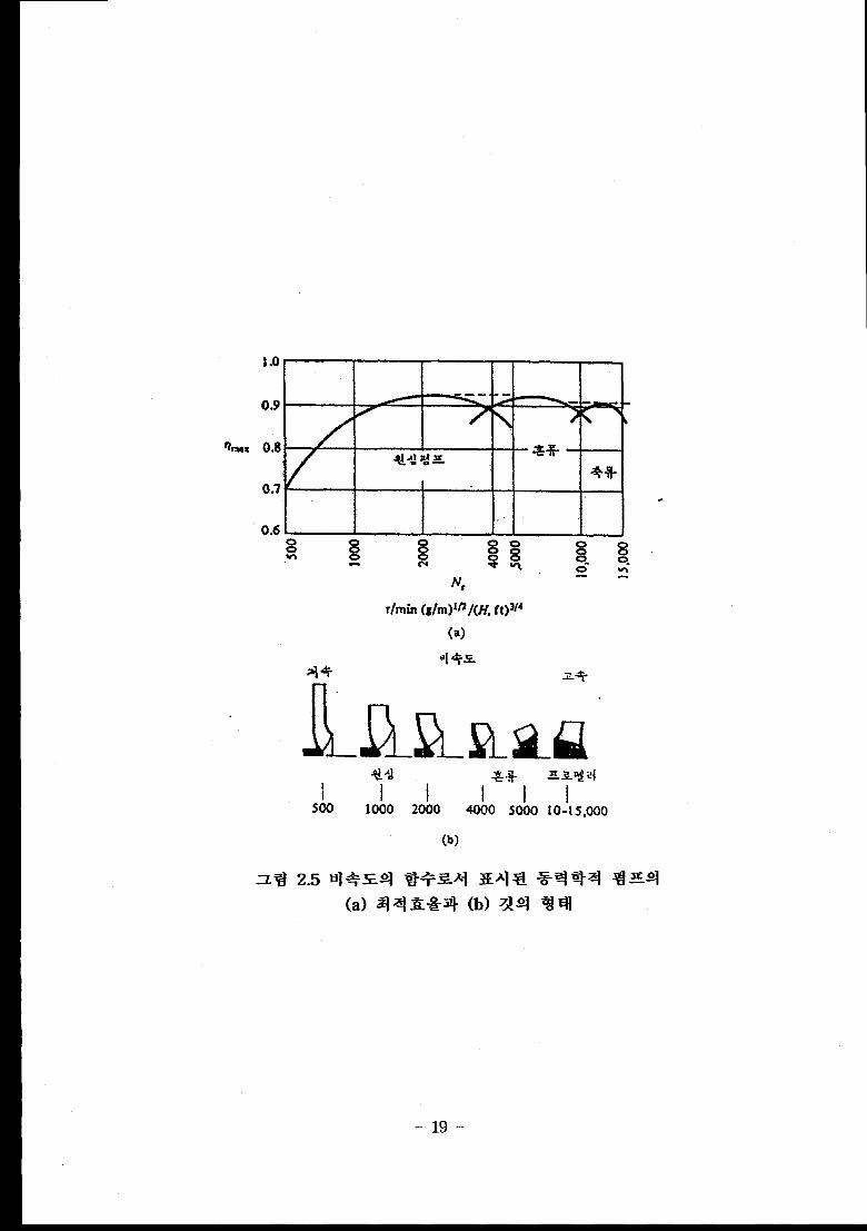
H]+=+ ~J+~Xj ~~] ~ *% ~~ ~~+ (a) Zj~ ~+j+
(b) XQl %IE! ........................................................................................ 19
*J~$sj~~J+=z} ‘4%%} a-+~ ~=q”Ll QAJ~=Ql +i~%=+~4.
.................................................................................................................. 20
%2?-4 =71% *3N a51-71-%X4%+441 “1~1% E+
(a) 2!% ?i 371 ~1+ 4+s7} 20% ‘i?q?l% q
(b) %lzj?2 +=~]~1 =717} 20% %q!l!l% ~ .......................... 21
qxq Q %-$ gsq gq~ ............................................................. 22
Classification of Centrifugal Pumps ............................................... 23
Single-Stage Pump and Multi-Stage Pump ............................... 24
Volute Pump and Diffuser Pump ................................................... 25
Horizontal Pump and Vertical Pump ............................................. 26
Canned Motor Pump ........................................................................... 27
71~g~ qx}syljqx]qs ............................................................... 28
7]+~4 +jx}s2Qj~x~ q.z+ijx] ..................................................... 29
7]++J& +lX}jzqq-x]qjs g-g+.j.jxl ............................................. 30
71+q~ +jX}aqq-xuqg ~~7] ................................................. 31
71+Qa +gi+-~~~x] %z+ %x] ~ xl x]++x1 ....................... 32
7]+%3 %JX}j!ilqqxllqg Xix] q ................................................. 33
Head-Flow Curves for LSTF Pump ............................................. 59
Single-Phase Head Homologous Curves for LSTF Pump ..... 60
Single-Phase Torque Homologous Curves for LSTF Pump . 61
Semiscale Intact Loop Pump Performance and Operating
Curves ..................................................................................................... 62
Serniscale Intact Loop Pump Performance Curves .................... 63
...– VIII –
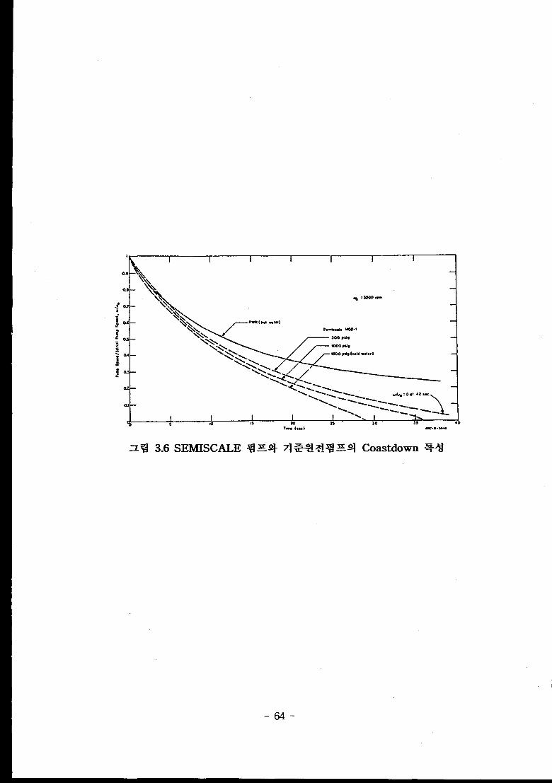
o ~ 3.6 SEMISCALE ~s+ 7]~% ~d% SQ/ Coastdown %~d ............ 64
~~ 3.7 Single-Phase Homologous Head Curve for MOD1 Semiscale
Pl_lmp...............................................................................""....`"...........".".- 65
~ ~ 3.8 Single-Phase Homologous Torque Curve for MOD1
SEMISCALE Pump (Corrected for Frictional Torque) =-.-”..=.. 66
z ~ 3.9 Steady-State Two-Phase Head Characteristics for the MOD1
SEMISCALE Pump ......................................................""..................... 67
~~ 3.10 Homologous Head Curves for SPES Pump ................................ 68
~ ~ 3.11 LOFT Two-Phase Head Compared to Experiment Data and
Full Size Reactor Coolant Pumps ................................................... 69
z ~ 3.12 B&W Two-Phase Homologous Head Data for First-Quadrant
Operation ..................+A.........................................................".....""...`"."... 70
z ~ 3.13 B&W Two-Phase Homologous Torque Data for First-Quadrant
Operation ................................................................................................
~ ~ 3.14 Comparison of Polynomial Fits to B&W, C-E, Creare and
SEMISCALE Single-Phase Head Characteristics ....................”.
=@ 3.15 Comparison of Polynomial Fits to B&W, C–E, Creare and
SEMISCALE Single-Phase Torque Characteristics ..................
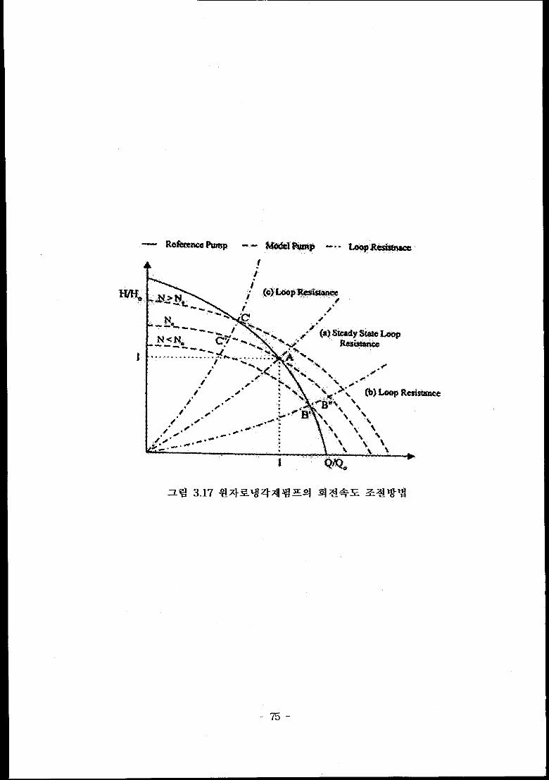
Z% 3.16 %x}~~~x]~ Z4 -i+a-++ %~d ...............................................
x% 3.17 ax}~qzl-xll $ Eq q ~+x ~~ti~$ .........................................
z% 3.18 Zj+~+~~~ ~}ZAJ~ ‘+l~j~ ~+~%~ (a) aA$%k~
(b) Cold Leg Break (c) Hot Leg Break ......................................-
3% 3.19 ~~a+j Zq $3?J3 ...........................................................................
z% 4.1 RCS Hydraulic Resistance Limits for UCN 3&4 Head (ft)
vs. Flow Rate (1000 gpm) ................S.""."......C..."................"..............
~% 4.2(a) RCP Performance Curve of UCN 4 for 1A pump ..................
z% 4.2(b) RCP Performance Curve of UCN 4 for lB Pump ................
z% 4.2(c) RCP Performance Curve of UCN 4 for 2A Pump ..................
=% 4.2(d) RCP Performance Curve of UCN 4 for 2B Pump .-.-.....=.....
Q ~ 4.3(a) Homologous Head Graph for UCN 3&4 Reactor Coolant
71
72
73
74
75
76
77
93
94
95
96
97
Pumps ................................................................................................... 98
2@ 4.3(b) Homologous Torque Graph for UCN 3&4 Reactor Coolant
–ix-
Pumps .c................................................................................................. 99
Z% 4.4 UCN 3&4 Pump Performance Curve ............................................. 100
Z% 4.5 Speed vs. Torque Curve ................................................................... 101
z ~ 4.6 Pump Head Degradation Multiplier vs. Void Fraction ............. 102
–x–
a
aN
Mlp
Ca
c@
D
g
/7.
H
/’20
I
1.
I*
1
M
mN
NPSH
P
P.
QRe
s
T
uvww’zz
Cross-Sectional Area
Homologous Speed Ratio, N/NO
Brake Horse Power
Cavitation Number
Actual Tangential Component of Velocity of the Fluid
Impeller Inlet Diameter
Gravitational Acceleration
Constant in Newton’s Law
Head
Total Enthalpy
Inertias
Inertial of Flywheel plus Motor Assembly
Inertia of Pump
Axial Length
Multiplier
Mass Flow Rate
Speed
Net-Positive Suction Head
Pressure or Power
Water Horse Power
Volumetric Flow Rate
Reynolds Number
Equivalent Blade Pitch
Torque
Flow Velocity in Pump
Velocity or Volume
Work
Pump Motor Powe~
Number of Vane
Height
output
-xi–

Greek symbols
a
B
B’
8
v
P
X2
P
T
4w
%bscrk)ts
1
2
c.v
G
h
b
i
L
m
P
R
r
s
Ss
sub
t
u
Void Fraction
Angle of Fluid Vector Relative to Rotor Periphery
Angle of Tangential to Rotor Centerline Relative to
Tangential to Rotor
Derivation Angle at Impeller Tip
Efficiency
Slip Factor
Angular Speed
Density
Moment
Flow Coefficient
Angular Speed
Inlet
Outlet
Control Volume
Gas or Steam
Head
Hydraulic
Inlet
Liquid
Model, Two-Phase Mixture, Meridonial or Component of
Velocity
Prototype or Pump
Model-to-Prototype Quantity Ratio
Rated Operating Value
Specific or Shaft
Specific Speed
Subcooled
Torque
Void or Steam
–xii-

-1-
-2-
(2.1)
(2.2)
-3-
(2.5)
w= rJ2 = rn(r~Qc@ = r~L?cfl)
(2.7)= rn(u2c@ – UICJ
-4”
~@Specific Work = ~ = — = u2c@.– Ulcfl
m (2.8)= gc(J’&?– J’qJ > 0
J?= gc(l?~– h)J= LJca??2 (2.9)
(2.11)
A – B@m/32’/fB=1 – $@lb2’ (2.12)
1 z.=s 27rcos/92’ ()
ln~>l (2.13)
-5-
*. NPSH(Net-Rxitive Suction Head)
-6-
U}. Suction Specific Speed
Suction Specific Speed+
Cavitation~ + q 01 ‘8 ?lq.
~ = Xpm(Qmm)”2‘s (NPSH3)3’4
-7-
(2.18)
-8-
-9-
-1o-
-11-
-12-
-13-

Design Pressure 2500 psia
Design Temperature 650 “F
Flow Rate 85,400 gpm%
1 Total dynamic head 337 ft1, 1II 1,190 rpm II
[ NormalOperating Temperature II 565°F1!
1Normal Operating Pressure at2,250 psia 1
SuetionMax. Heatup/CooldownRate 100 OF/hr
, 1
1 Power 13.2kV, 3ph, 60HzI
NPSH 175 ft
Design Life 40 year
Number 4
-14-
——
I
! I
E!E-l-j
l— ,
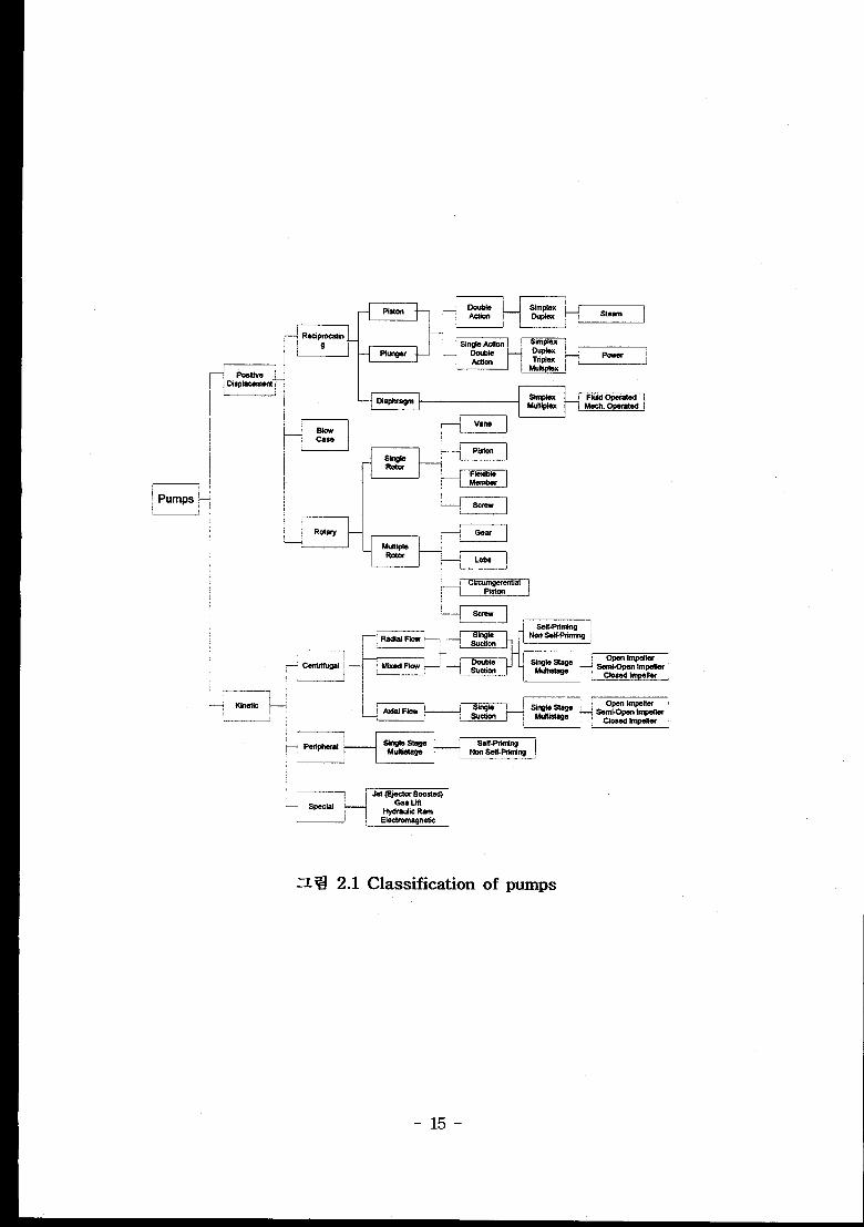
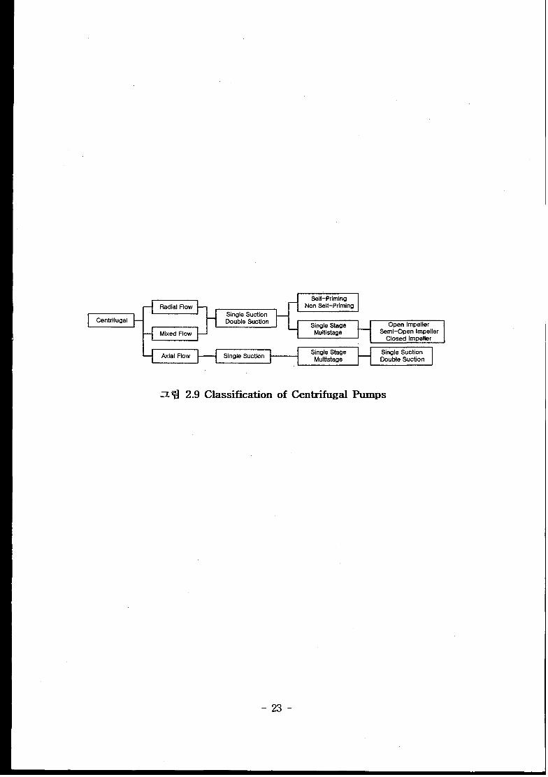
Z ~ 2.1 Classification of pumps
-15-

-16-

(a)
t
Ca
f
Velocity
Impeller
Relations
(b)
for Flow through Centrifugal Pump
-17-

\
z% 2.4 Logarithmic Spiral Vane
Note : Vane Angle /3’ is Constant for All Radii
-18-
%ux
iv,-.
r/rein(g/m)ln/(H, f t)3/4
(a)
‘4+=J?+
-
.L!I-LLL?LSUJ
-19-
-20-

(
R, bhp
D= 10=constanL
Q
H, bhp.-. ,
(a) ‘ 1 (b)
-21-

(1)
1
—-.
-22-
NonSelf-Priming
Centrifugal Oouble Suction Open ImpelferSemi-Open Impeller
Closed fmpeller
Single Stage Single SuctionMulfistsge DoubfeSuction
1
- ~ 2.9 Classification of Centrifugal Pumps
-23-
.. . .
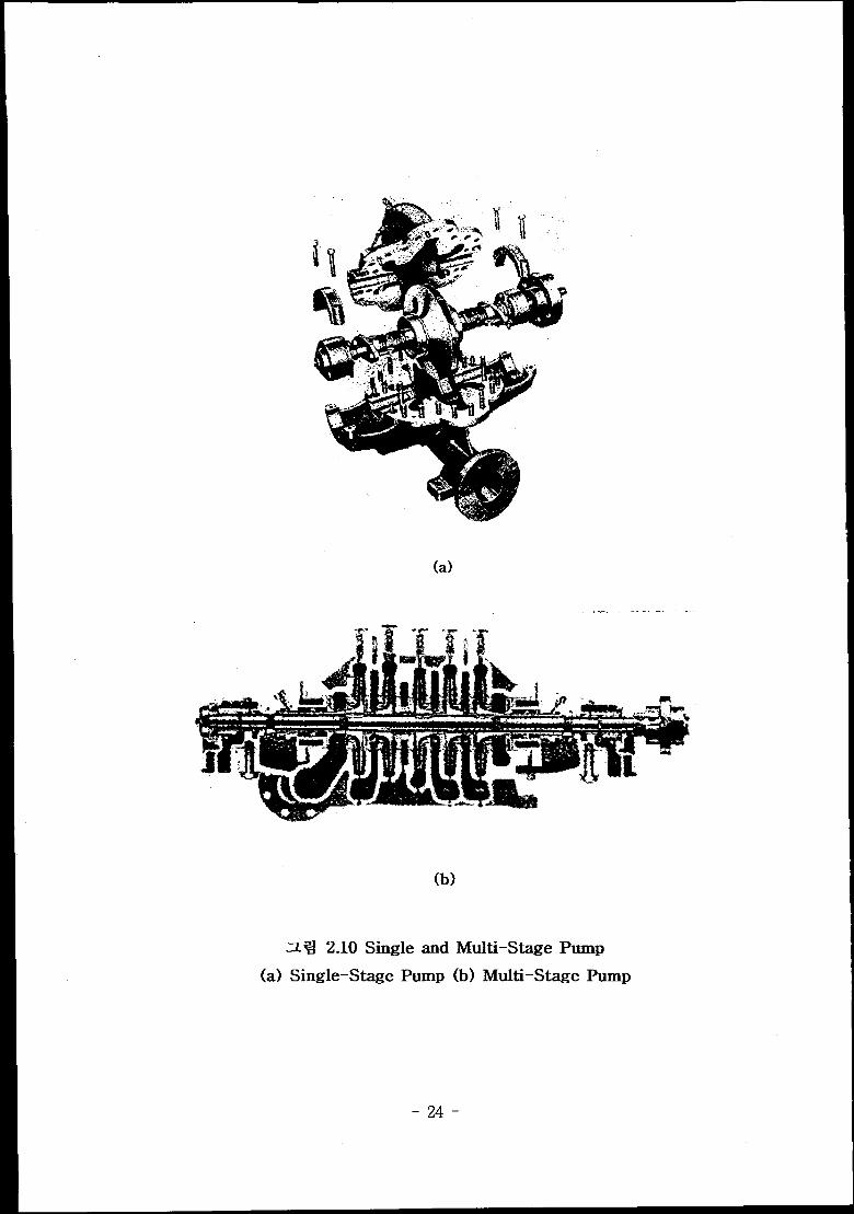
- a 2.10 Single and Multi–Stage Pump
(a) Single-Stage Pump (b) Multi-Stage Pump
-z4-

(a) (b)
z ~ 2.11 VOIUt,e Pump and Diffuser Pump
(a) Volute Pump (b) Diffuser Pump
-25-
S-%iii
(a)
(b)
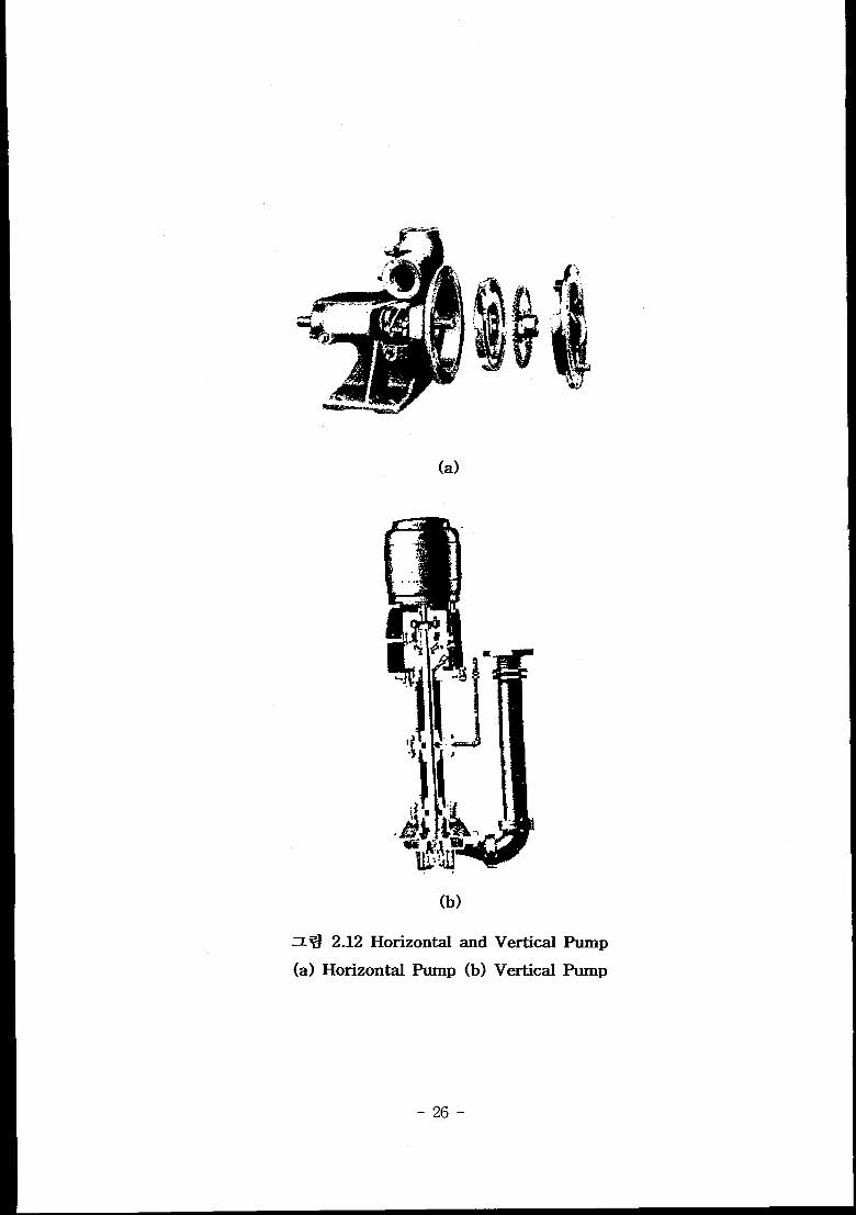
Zq 2.12 Horizontal and
(a) Horizontal Pump (b)
Vertical
Vertical
Pump
Punlp
-26-

,.. . . ... ....... ,.:...... , :.. ... ; A
-~ 2.13 Canned Motor Pump
-27-
~=
Y
JNG
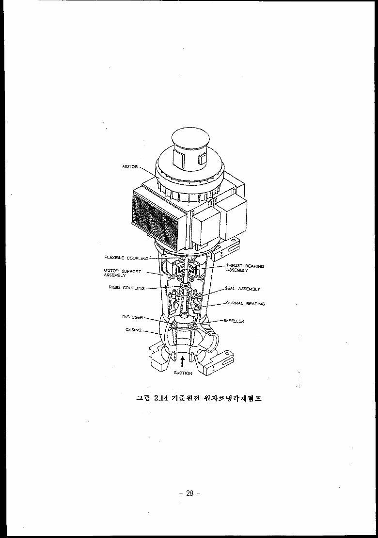
z%! 2.14
-28-
A ....
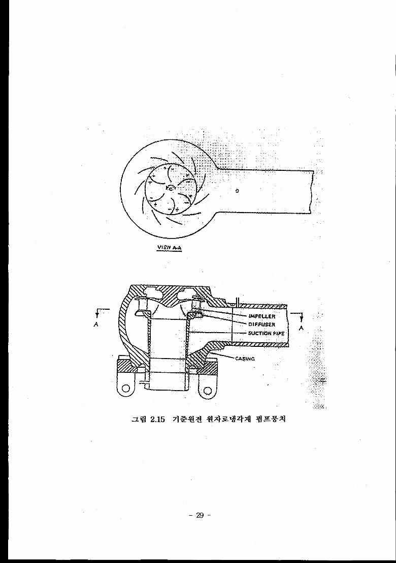
-29-
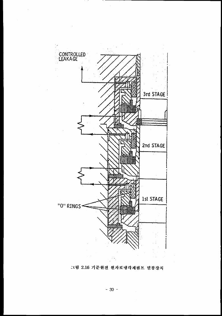
2M STAGE
W3Lwal%\\\
1stSTAGE
I
-30-
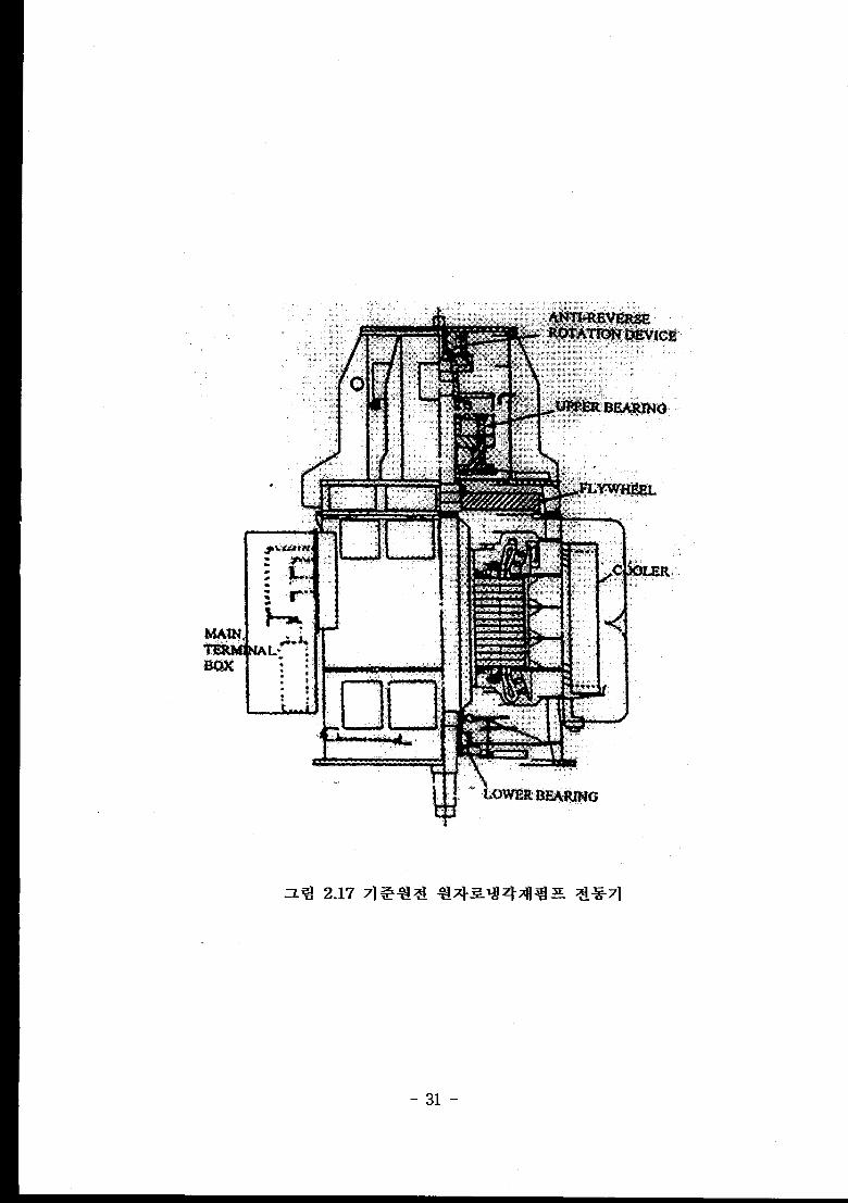
-31-
U.1
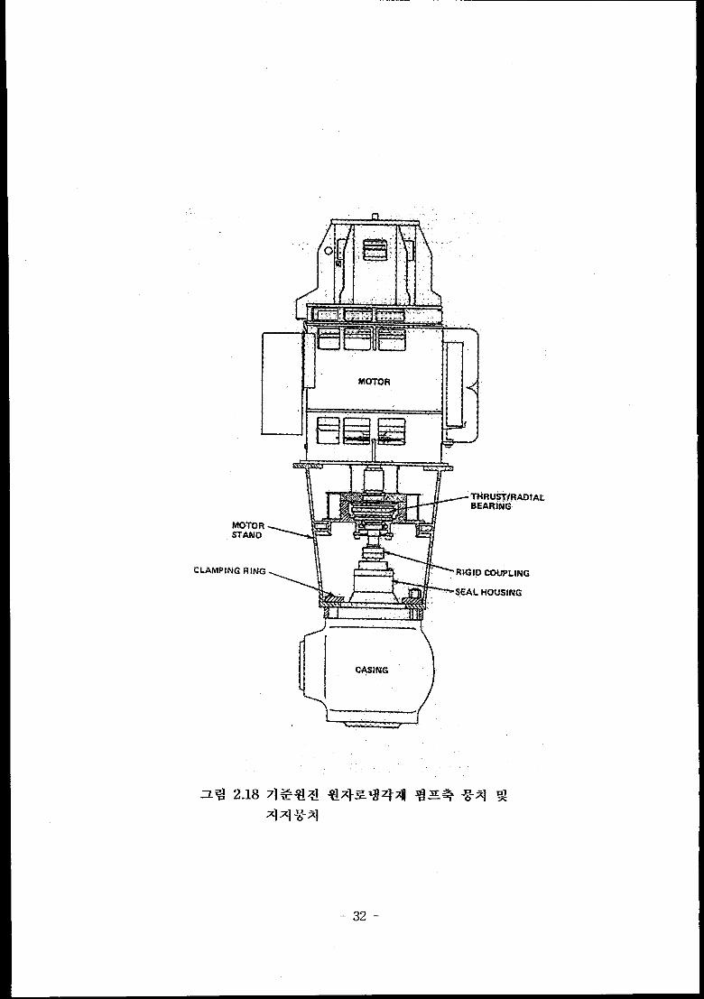
-32-
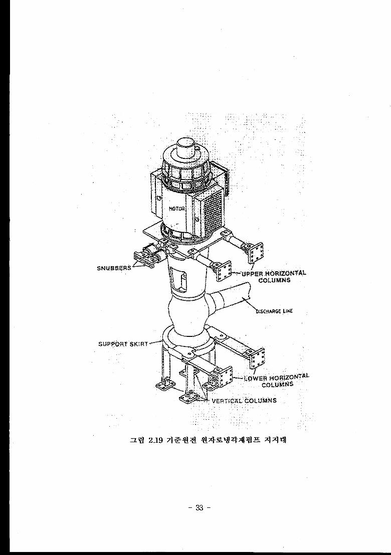
-33-

(i%),=(%+ -. +-*21+ (Flow Coefficient) (3.1)
-34-
(7%),=(7%).: ‘$?j 21+ (Energy Coefficient)
( Pl$lY)@ = ( Pl$D)m: %+21+ (Power Coefficient)
(*), = (+).: I%= Xl+ (Torque Coefficient)
(3.2)
(3.3)
(3.4)
(1)
(2)
(3)
(4)
(5)
-35-
-36-
—
.
—
—
-37-
-38-
1
~ dwmm dt
&=~T—1P dt
(3.6)
Ij = Inertia of Pump,
1.= Inertia of Flywheel plus Motor Assembly
dwm— = Time Rate of Change of Motor Shaft Speed
dt
*dt
= Time Rate of Change of Pump Shaft Speed
~ T= Sum of Torques Acting on the System
-39-

—
2)—
—
—
.
—
—
~ XLq ~ ~ ~s + al Stator Jacket +% oll $%! ‘~~1q Rotor~ Stator ‘}
01~ Fan+ ~R+ Blower~l %Q)%~fi]~ %Rlq. O]q %}+2 q~%~~ +il
~~1 + ‘~ ~%~ ril01Ej~ 947] ~ %} ~+) ~~ +=] & q++ %}~.
“ Pump speed (Capacitive probe and electronics provided)
“ Pump shaft torque (PRONY brake and load cell provided for motor
calibration)
. Pressure and temperature taps at the casing inlet and discharge
flanges, pressure between the impeller and stator (Port provided
without transducer)
“ Fluid temperature in the seal cavity (Two ports and thermocouples)
“ Shaft motion normal to the axis during checking tests (Two shaft
displacement probes and electronics)
“ Motor stator temperature (Two thermocouples implanted on the
stator)
“ Inadequate oil and water (Bearing lubrication system and the
cooling water circuit with flow switches that interlock with the
power supply)
-41-

P: average fluid density
Pump shaft torque : T.= (P/N) x Vm (3.10)P ~: measured pump motor power
N : pump speed
?~ : PLU_IIPmotor efficiency, function of pump speed and voltage
to pump frequency ratio
“43-

H(zJ,a~, a) = lYlo(v, a~) – Mb(a) [ hlo(o, a~) – IZzo(v, a~)] x Rr (3.13)
~v, aN,a) = Tlo(v, aN)– M~(ff) [ t~@(V, ahI) – t~@(V, aN)] X T. (3.14)
H : Pump head (m), N : Rotor speed (rad/s),
Q : Volumetric flow rate (m’/s), T : Pump torque (N-m),
a : Void fraction (-), Rh : Head ratio (-),
Mh : Two-phase head multiplier (-),
Mt : Two-phase torque multiplier (-),
h : Homologous head ratio head/rated head (-),
t : Homologous torque ratio = torque/rated torque (-),
v: Homologous flow ratio = Vol. flow rate/rated vol. flow rate
(-),
aN : Homologous speed ratio = rotor speed/rated rotor,
Subscript r : Pump rated operating value.
~++% 2s %= N%I”l +%~%i~.
“ 4 %A1 % (Flow rate vs. pump head at various pump speed, flow
- Tests of the water injection to the motor and bearings
. S#2E loading test (Thermal stress, shock wave %01] ?!= + $5!%z1
ql q %1 G]5=)
-44-
7. SRI
-45-

-46-
-47-

“48”
(3.18)
hl(P/Pv)= - *(+ - +) = “gT.-T:) (3.20)
-49-
AP= POhfgAT& = pghfg AT&
R? T (3.21)
c.= ‘$ ~g%gAT~ = v~hfgATsub—— ~—Pl U2T VgU2T
(3.22)
-50-

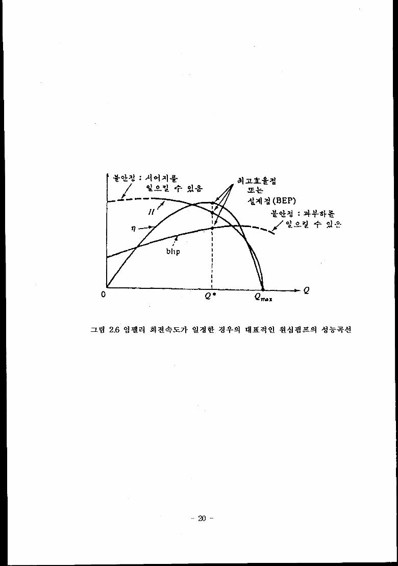
Head [d 1 la
Diemeter dti dd Id
Area a& da’ la’
Volume VM dd= . a& . V& Id’
RCPRated~hu23@3iC Q.1/2
aoR IdFlow Rme
N,-1/2 1/2
RCPRatedSpeed ad [d
P*R312
RCPPower aOR[d
T213
RCP Toraue IXIR ad b
I IIR 3/2 2[3
RCP herbs aoR L I
* Pw= @@’Hal
* From angular momentum equation :
~ dw— = Tw~g, where w = angular speed
dt
-51-
2 I 4 I 1/2‘1 Centrifugal pump Centrifugal pump
Pump typeCanned tme Shaft Sed tyFE
~ Rated flow rate, gpm ~ 855.94 I 88454.2 I 1/103.3
~Rated pump speed, rpm ~ 1800 I 1190 I 1.51/1
~ Rated pump head ft ~ 32.81 I 275.6 I 1/8.4
Rated pump torque,40.7 —
Ibf-ft
Momentum of inertia,
lb-ft212.82 —
I Water volume, fti 0.83 84.74 1/102.1
Specific speed,4.46 x 1000 6.08 x 1000
( ?ll?nG1’ ft3’4)1/1.36
-52-
n Requirement common to pumps for the operating and broken loops IIEVl%=L79at Q=0 IIQ/Q~ = 1.52at H = O (FLand Q. are the normaloperationpoint)
12500psig650’3?
Pressure:2500 psig to 1000 psig in 0.25 seconds 1000 psig to O psig
in 20 seconds
Temperature: 550 “F to 290 T in 20 secondsI
Water or steam II(a) Drive system friction torque must be sufilciently low and
repeatable to permit measurement of the normal operating
impeller hydraulic torque within ~ 20°A
(b) A torque measurement device must be provided for the
measurement of impeller hydraulic torque (calibmted motor is
acceptable)(a) The pump must withstand 200 cycles of cold start to operating
conditions through depressurization.
(b) Bearing and seal replacement between tests is acceptable, but not
desirable.
(c) 200 cold hydrostatic leak tests must be tolerated following
installation in the test systemASME boiler and pressure vessel code, Section IU, “Design of Class
II Pumps”, applies to the pressure boundary design and hydrostatic
proof test conditions.The following measurement must be provided for in the design of
the pump (Ports provided, transducers specified) :
(a) Pump rotational speed
(b) Pump shaft torque
(c) Pump pressures at the casing inlet and discharge, the seal cavity
and the impeller discharge ( between the impeller and stator)
(d) Fluid temperature in the seal cavity
(e) Fluid temperature at the casing inlet and dischargePump impeller : centrifugal, single stage
Pump casing : single axial inlet, single radial discharge, vaned statorllJ-fal
g~metrytype diffuser
iriterface with’:’
S&misele ‘ Coordinate with Semiscaie design personnel
existing piping
-53-
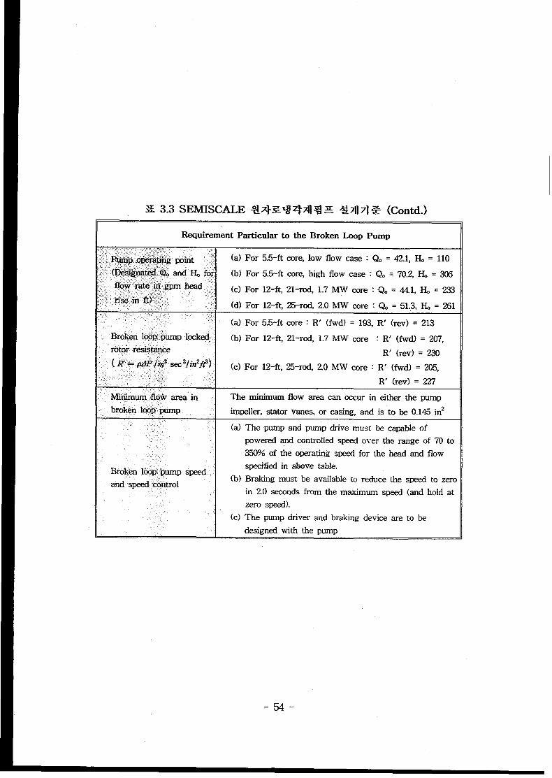
X 3.3 SEMISCALE %!x=q q~ % = &Z] 71+ (Contd.)
Requirement Particular to the Broken Loop pump,.‘.:, :, ; ,.’::,..?~., ,,:,
~~~p o&3@@ point .‘ (a) For 5.5-ft core, low flow case : Q. = 42.1, IL = 110
~ (b$@pa~~$?e and & for (b) For 5.5-ft core, high flow case : Qo = 70.2,~ = 306
fk& m~$;,;jmm ~ead .,~ (c) For 12-ft, 21-ro4 1.7 MW core : Qo = 44.1,& = 233~,, .. .... ,!: ris; in ft’:.~’ :<, (d) For 12-ft, 25-rod, 2.0 MW core : Q. = 51.3,1% = 261,., .. .. >>.~.’
(a) For 5.5-ft core : R’ (fwd) = 193. R’ (rev) = 213
Broken lQ&Rpump locked. (b) For 12-& 21-rod, 1.7 MW core : R’ (fwd) = 207,ro@ resi;@ice
(K= pf?P/k2 sec2/in2j#]R’ (H3V)= 230
(c)For 12-ft, 25-rod, 2.0 MW core : R’ (fwd) = 205,.’.. <.,.,:’::. R’ (rev) = 227..
Mir$rnum floiv area in The minimum flow area can occur in either the pump
broken kx?p~pump impeller, stator vanes, or casing, and is ‘to be 0.145 inz,:
The pump and pump drive must be capable of
powered and controlled speed over the range of 70 to
350% of the operating speed for the head and flow
specified in above table.
Brakhg must be available to reduce the speed to zero
in 2.0 seconds from the maximum speed (and hold at
zero speed).
The pump driver and braking device are to be
designed with the pump
-54-
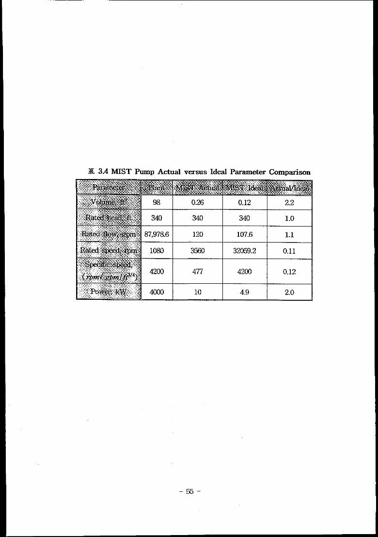
S 3.4 MIST Pump Actual versus Ideal Parameter Comparison
0.26 0.12 2.2
340 340 340 1.0
120 107.6 1.1
32059.2 0.11I I 1 u
-55-
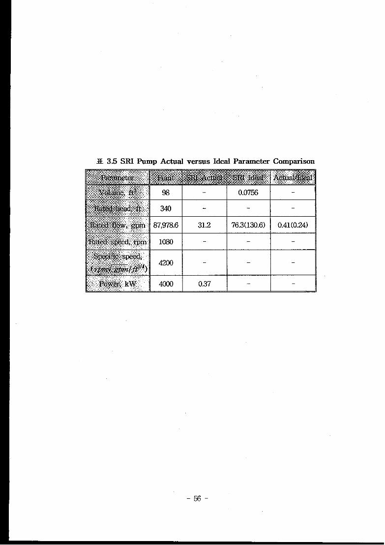
3E 3.5 SRI Pump Actual versus Ideal Parameter Comparison
-56-
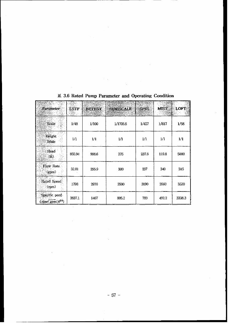
X 3.6 Rated Pump Parameterand Operating Condition
1/48
1/1
855.94
32.81
1798
3837.1
1/100
1/1
998.6
255.9
2970
1467
1/1705.5
1/1
275
300
3500
805.2
-57-
1/427
1/1
237.8
237
3090
789
l/817
1/1
119.8
340
492.2
l/1
315
3530
3338.3
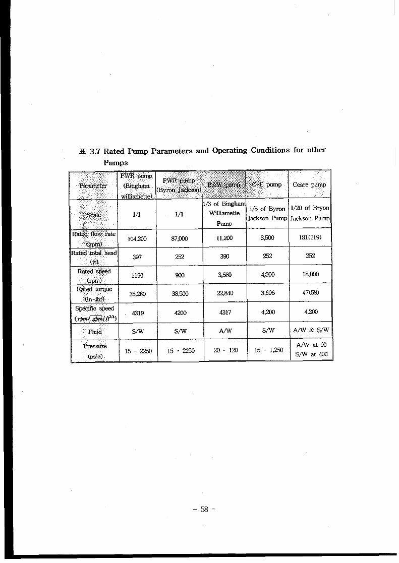
3E 3.7 Rated Pump Parameters and Operating Conditions for other
Pumps:-~.X w: ,’ WE ‘i$mp.,.<,,,=
2 .,,+,,Pa@je@ Care pimp.:...”.:..:,,:,,’ :.:,,),;,.,.,‘,: - ...+:, 1/3 of Bingham
,,+&@ 1/1 1/1 Wllliamette1/5 of Byron 1/20 of Bryon
,, JacksonPump Jackson Pump-;,.,, Pump..i’..... .
Rati2$j flo$&Xe,: 104,200 87,000 11,200 3,500 181(219)
. .{.~w$,,
Rated total head397 252 390 252 252
(fi) ‘.
‘R++ .+@xl1190 900 3,580 4,500 18,C00
(~
Ri@ tofq$e35,280 38j500 22,840 3,696 47(58)
{in-i@]Spi+6ific s&ed
4319 4200 4317 4,200 4,200(rpya~&j#4)
:,.Fl~~ Sv’w WV S/w Nwtk s/w
Pressure A/Wat9015-2250 15-2250 20-120 15- 1,250
(psia) S/W at 400
-58-
‘f,’
+..= ‘
RrAed Candition
(1800 rpM, 194.4 m3/h)
\
~.
I -150 -1oo -s0”050/.
240 w
—-s -
PC-AData120 rpm
x- -x PC-8 rata
-lo -
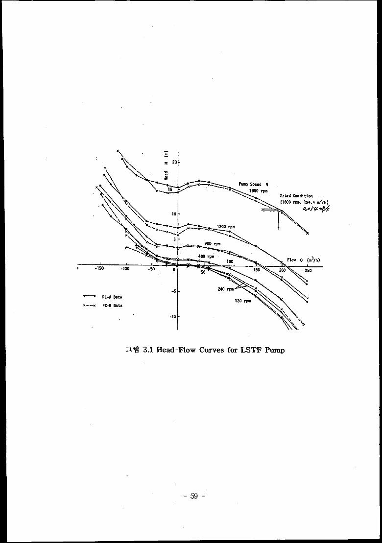
n% 3.1 Head–Flow Curves for LSTF Pump
-59-

●
\
o
l-i: Pump Head ~
w: “Pufnp Speed
Q: Flow Rate
Subscript R :
Rated Condition
h=H/tiR”
a sW/ld oR
t
-1 0
-. ,.
h/a2,
h/ .iz
z ~ 3.2 Single–Phase Head Homologous Curves for LSTF Pump
-60-
●
o
0
-1 0
T-fl=
‘f
‘R - ‘fR
1 Q)AA
A
A
A
/“ 1
-/
T : Shaft Torque . “
u : Pump Speed
Q: Flow Rate “Fig. 5.2.44 Single-phase Torque
Homologous Curvesfor PCIA
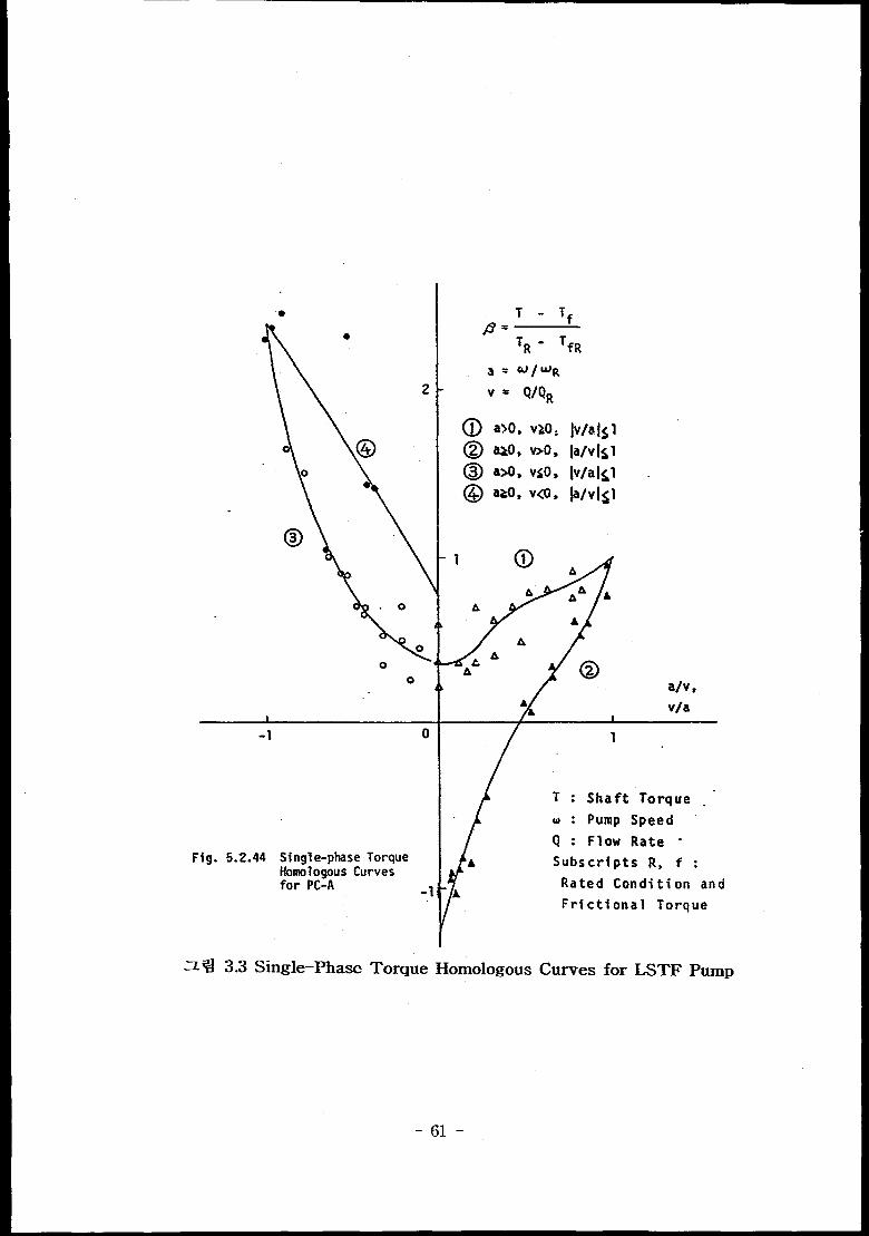
ZY4 3.3 Single–Phase
-1/
b Subscripts R, f :
Rated Condition andA
Frictional Torque
Torque Homologous Curves for LSTF Pump
-61-
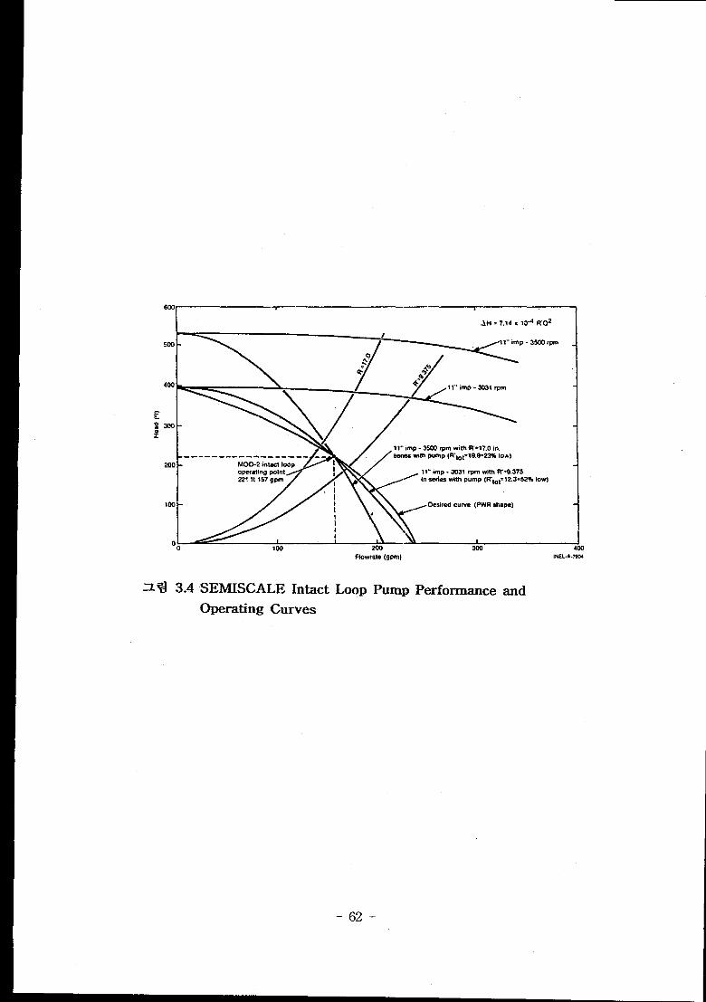
1 AH = 7.14X 10⁴ R02
+- P---------------—----MOO-2 imactloop IOpe.ratin9ceint I,.
I
.. ..... .... .. . ..W@S withPWIIP(R,oi= 19.9=22%104.}
in serieswith pump FI’lot=l 2.3=52%tow)
‘;l~=ZlmlCO
SEMISCALE Intact
Operating Curves
Flowrate(gpm)
Loop Pump Performance
aINEL.A-7W
and
-62-
60C
40C
2C4
o
-20C
-40(
=: -60C
+
-m
-1OOC
-1200
-140(
-160C
-180C
:1 1“”imp -3031 rpm with R’=3.37 in serie
\Y\ IoIal H =us. ,.
\\ ~,+ 1“ imp, 3500 rpm with R“=17.0in.
\ &series. total R“=19.9
\
\\- ~ .. . . ,.
1\ PWli N=G.76 No
i /’+&f
\\\
i \*
\\ PWR. N=NQ hkwkm
\\\\
\\ \
\ \
\.\* \
N=o (locked
19.9?1 \ \
o 100 200 300 400 500 [(9wX INEL-A-7905
7
+
o
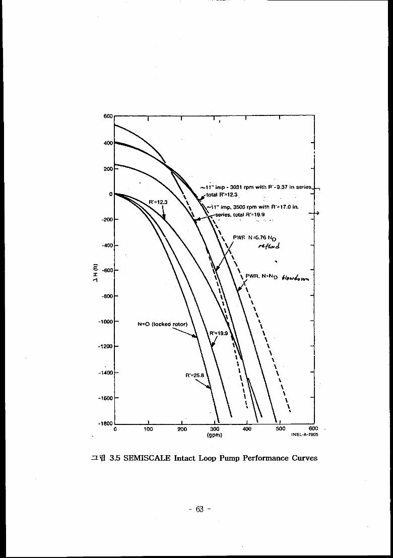
~ ~ 3.s SEMISCALE Intact Loop Pump Performance Curves
-63-
-64-
,d I HVN / I
I
● ● M/Mt
● * 0/0,● ● It/M,
Es:.,,
Oldpollrn t-O, +N) {~:
Morml*tT*?bIms (-O.-W { ~~
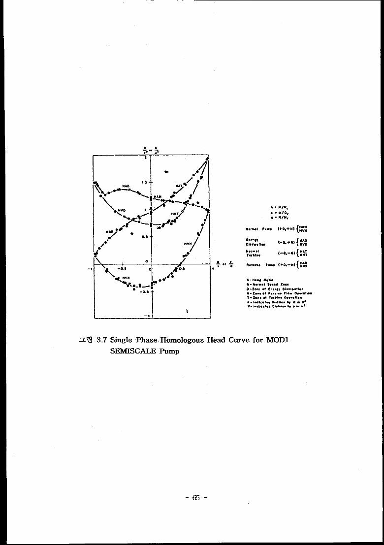
~ ~ 3.’7 Single–Phase Homologous Head Curve for MOD1
SEMISCALE Pump
-65-
I -0.5 c
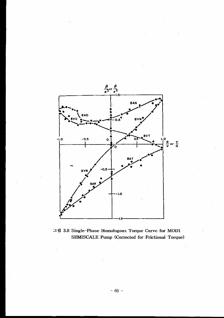
z ~ 3.8 Single–Phase
SEMISCALE
I
“-1.0
—-L5 I
)av-or-wa
Homologous Torque Curve for MOD1
Pump (Corrected for Frictional Torque)
-66-
\\\%
:;~”..Kpho’”\ \\ \
——
a - VOM rroetlwl (%)
Q - VOl.m*tfle flow (Q*)
\\
\\
ti - Pump Hood(tt )N - lmp.lf.r SP@sd(rpm)
\ \ ‘\\
\
\
\
\ ‘, i,
‘\ ‘\ \
15.0O/Ii (lt2,pm/tpm)
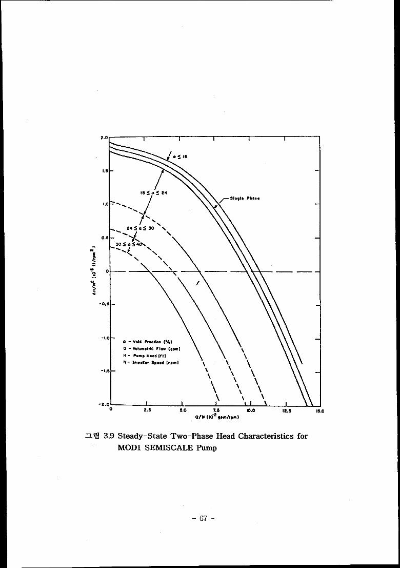
= ~ 3.9 steady–state Two–phase Head Characteristics for
MOD1 SEMISCALE Pump
-67-
0’5I.}0 .ae -06 -0.4 -0.2 0.0
.~.a5”--, ./-” --
“%.. .. .. .. .
.1.0
-1 s
-2a
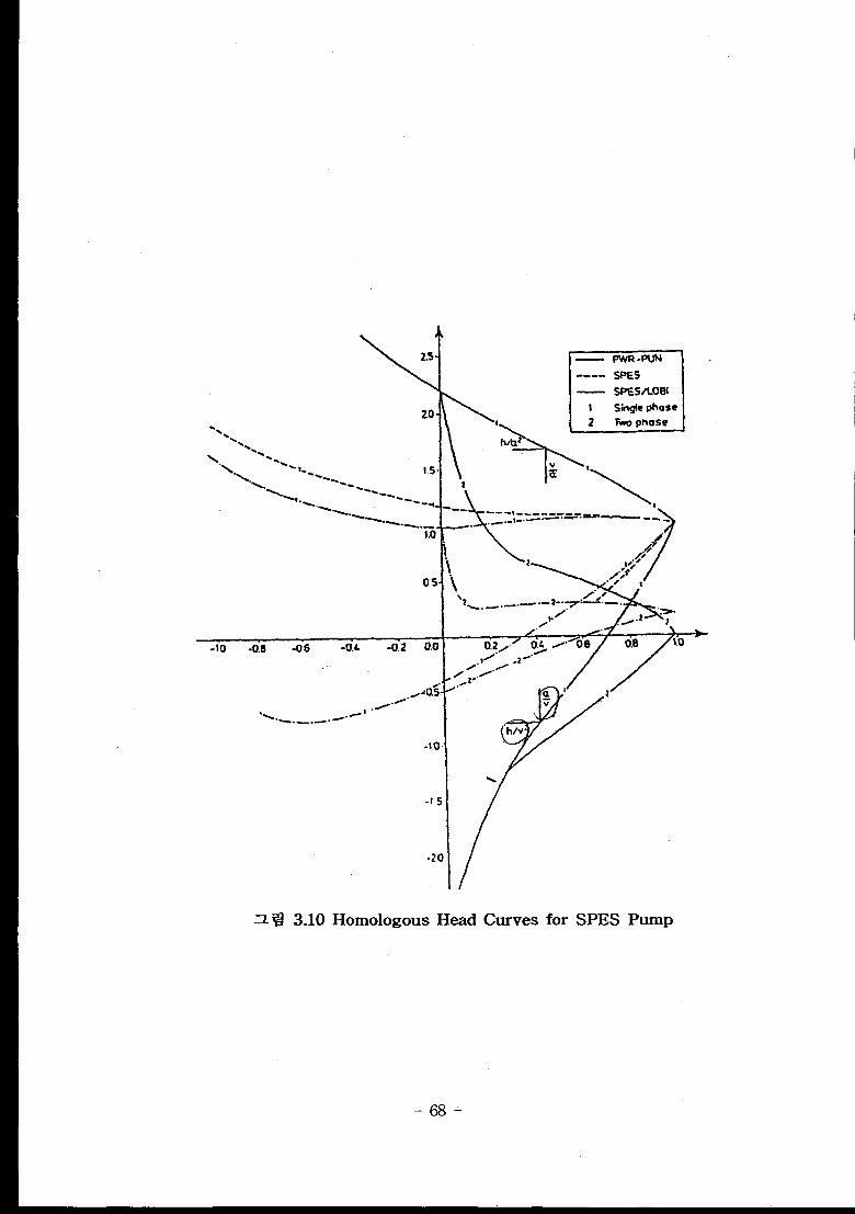
Homologous Head Curves for SPES Pump
-68-
0 “02 0.4 0.6 0.8 1.0
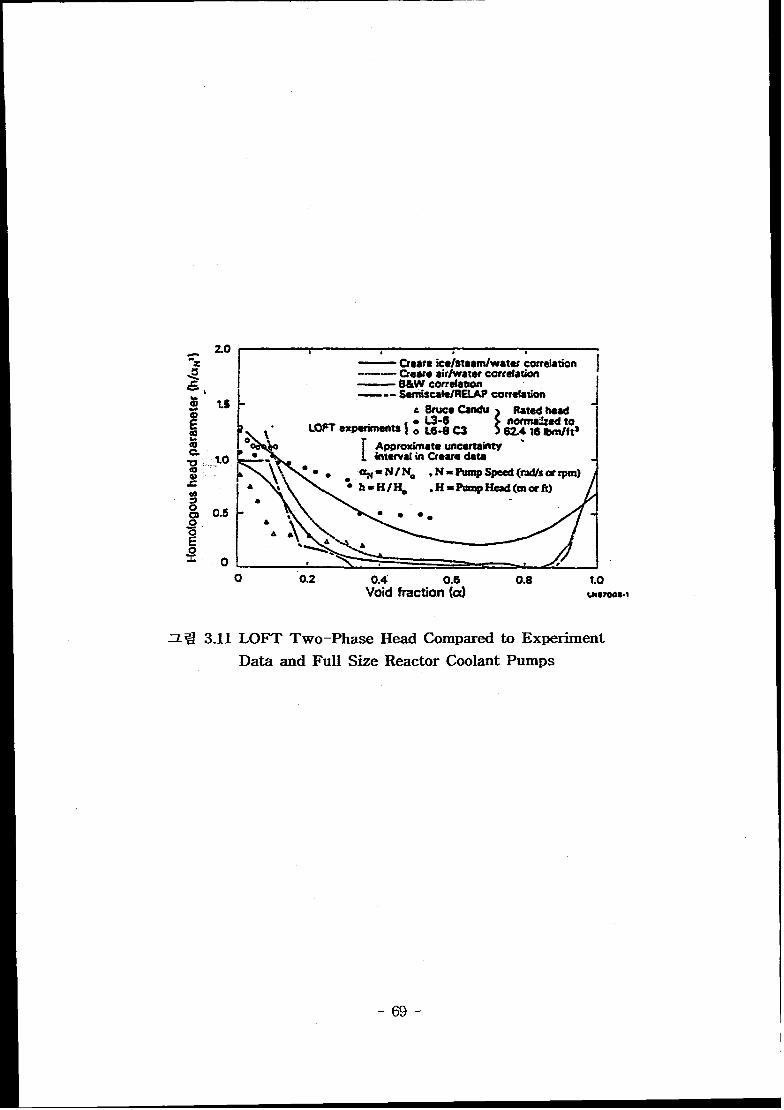
z% 3.11
Void fraction (a) W87008.1
LOFT Two–Phase Head Comparedto Experiment
Data and Full Size Reactor Coolant Pumps
-69-
1.6
1.4
1.2
1.0
0.8
0.6
m
~0.4
8N
$ 02
~’
8 0
mS2
j .0.,
2
2.0.4
.0.1
-0.
.1.
.1.
.1.
“\& ---
----. --<w void Fractmns
y * - .-\\
-- —. (o-3)
\ -_____ --{sJo)
/
/( 10-20)
I
i
Pwnp-SpeedP1OWRate, a#v or v/aN
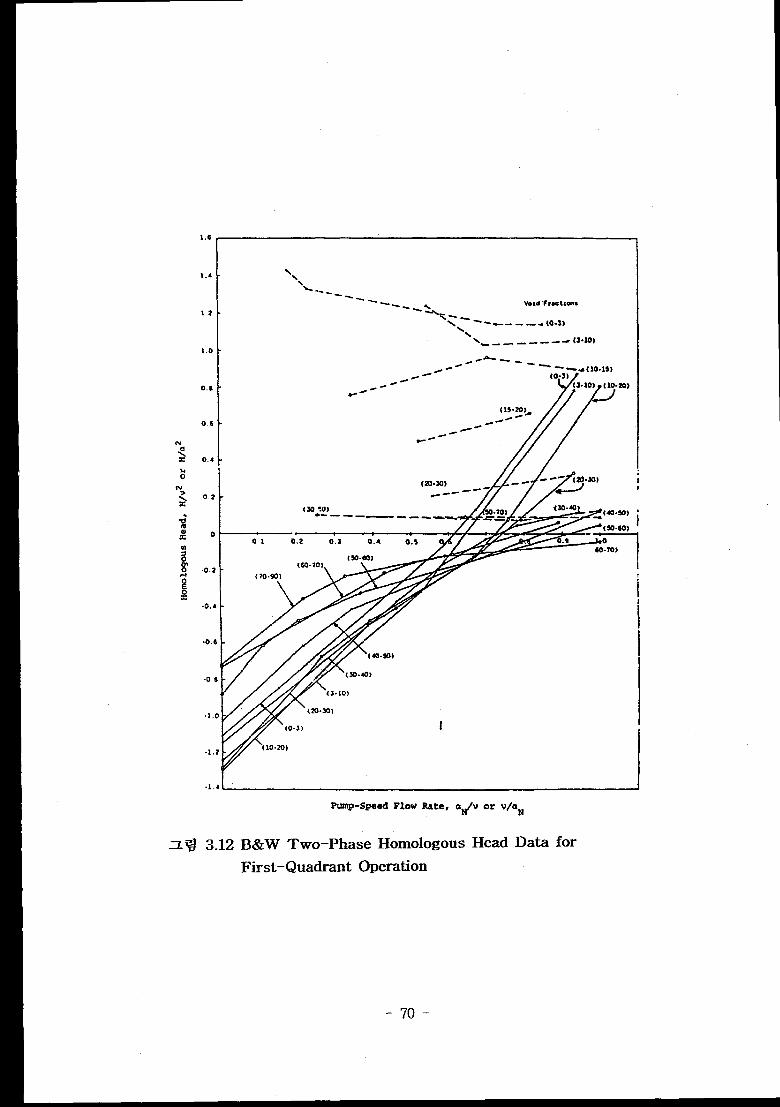
z 9 3.12 B&W Two–Phase Homologous Head Data for
First-Quadrant Operation
-70-

1.4
1.2
1.0
0.8
0.6
-0.6
0.{
.1,(
.1.:
.1.
(‘G:‘ylo to 15X)(WUUN) ~-~.
/
A-. = -= -----== -“--/ -- tom%
-----Oten -------- ~- (38elo5)
-----~----
a----(0 t> s%)
..
~-(10 to Zcl)
—
Pwmp-Speed Flow Rete, a v or v/aNd
z ~ 3.13 B&W Two–Phase Homologous Torque
First-Quadrant OperationData for
-71-

1.6Creare
1.5
1,0 — Semi scale\
0.5 —
I0.03.0
Homologous Flow Paramatar,
-0.5 —
-1.0 —
1-
3 ~ 3.14 Comptison of Polynomial Fits to B&W, C–E, Creare
and SEMISCALE Single–Phase Head Characteristics
-72-
1.6
1.5 L
0.0 t * I\
I 1t * , I I *
I I 4I t 1 ,
“ 1.0I
‘/\I I I
20 3.08
Honwlogous F1OWParameter,
-0.5
-1.0
[
\,* \
\\
,
i’
\\\
\ \
v/aN
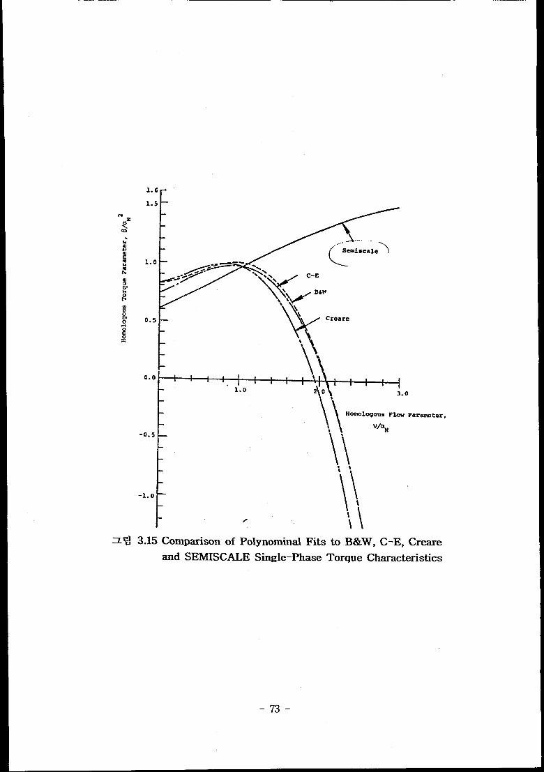
Z= 3.15 Comparison of PolynorninalFits to B&W, C–E, Creare
and SEMISCALE Single-Phase Torque Characteristics
-73-

I1*”**”’’””’’’””’””””””*~’~’
I
-74-
-75-

a) b) o c]
-In.
●
-76-

A
H ,
no Case c)
LOOP RESISTANCE
Case b)
1. -
/
,/’
/’
/ Reference Pump,/
1,
-77-
al1 z! a~E=wbwl=q +..WWJ%
-78-
-79-
Lower Power Shutdown
“ Pressure Drop
-81-
-82-

-83-
-84-
-85-
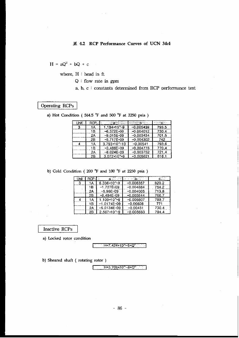
X 4.2 RCP PerformanceCurvesof UCN 3&4
H’aQZ+bQ+c
where, H
Q
a,
Operating RCPS
: head in ft
: flow rate in gpm
b, c : constants determined from RCP performance test
a) Hot Condition ( 564.5 “F and 500 %’ at 2250 psia )
Unit RCF ,a’.:: . ‘“b “c3 1A jAl 94*10A-9-— -0.005439 793.5
lB +i.372E-09— -0.004012 730.42A “_ -9.01 5E-09 -0.003434 701.52B -5.71 7E-09 -0.004302 742
.—. _ 1A4 _3.793*1 OA-l o -0.00541 793.6— -–.M–– -_-3.486E-09.--..—,. -0.004778 770.4
2A -8.024E-09 -0.003752 _ 721.4.. ... .-.,—- .. ..-—. ..”“.. .. ..2B 3.072*1 O*=8 -0.005821 816.1
b) Cold Condition ( 200 % and 100 % at 2250 psia )
Unit RCP a.” b. c.,,3. _ .......IA.. !133.!3*UYX!. ,.,.,.......3.JXKXZ. . . ...f!2U?.-._..
. . . . . ... .....1. J2&Q2. . . . . ........QX!!MXM... . . .. ..........z%l..z...... ....g.... . ...-5.! MEQ.. . . . .. ... .................... . . ...... ...... . ......yo..+ ........-0004005
-8.494E-09 -0.003844
. . .M..... !....1Q9.*K!:Z%.. -,-.9.M!5!W..”.. .-......+””Tz----4.-1. .OI.74.E.*9,., ,-,,,””~.,.gg51a
.. g,.. ....3..!XWE3? ..-.....+xmsll... .......ZVM........2.567*1 0“-9 -0.005683 794.4
Inactive RCPS
a) Locked rotor condition
I H=7.424*1.O’’-8*Q’ 1
b) Sheared shaft ( rotating rotor )
I H=3.709*1OA-8*Q’ [
-86-
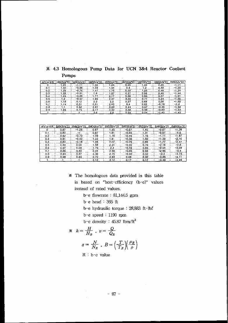
3E 4.3 Homologous Pump Data for UCN 3&4 Reactor Coolant
Pumps
x The homologous data provided in this table
is based on “best-efficiency (b-e)” values
instead of rated values.
b-e flowrate : 81,144.5 gpm
b-e head :365 ft
b-e hydraulic torque : 28,883 ft-lbf
b-e speed :
b-e density
1190 rpm
:45.87 lbm/ft3
-&
a=+ $ ~=(%)(%)R : b-e value
-87-
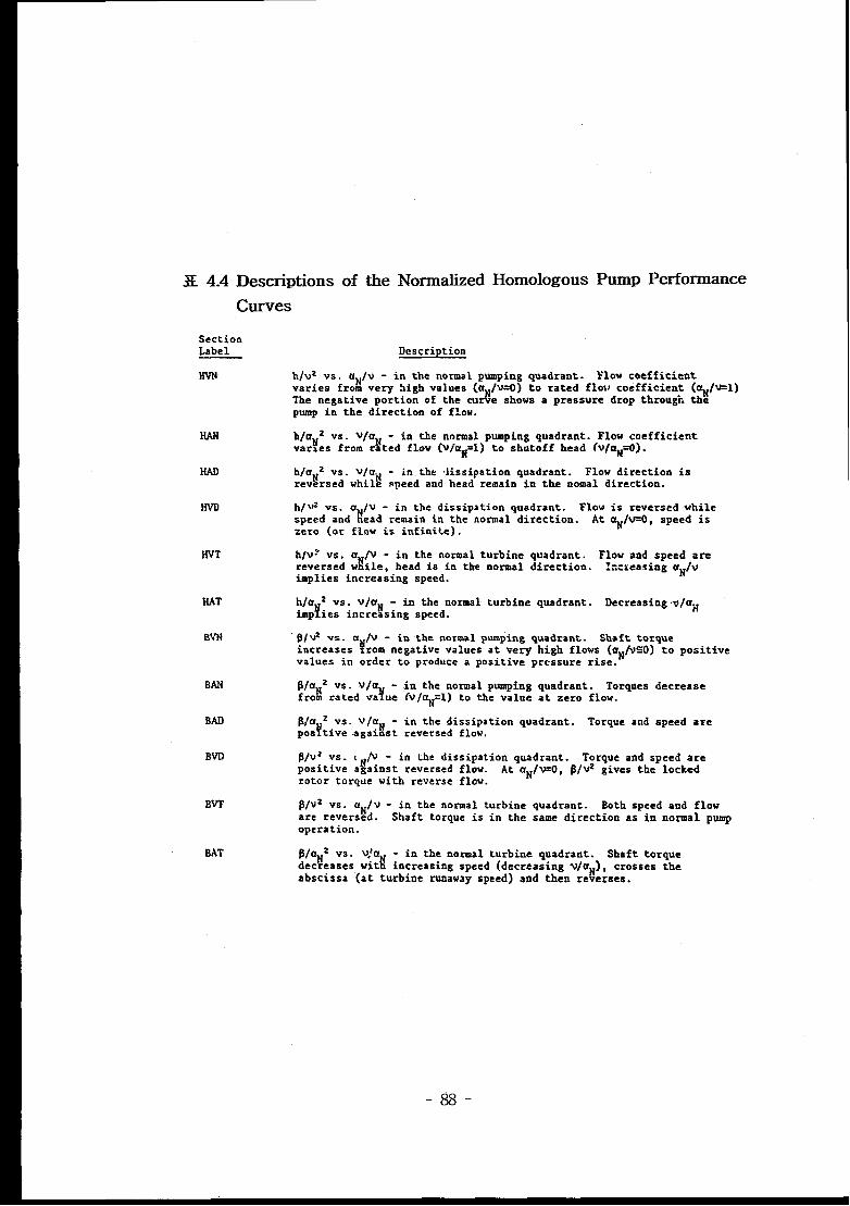
X 4.4 Descriptions of the Normalized Homologous Pump Performance
Curves
SectionLabel
HvN
Description
hlvz Vs. uNfv - in the norms 1 pumping quadrant. Flow coefficientvaries from very high valuea (aN/v=O) to rated flov coefficient. (tiN/v=l)The negative portion of the curve shows a pressure drop through thepump in the direction of flow.
HAN
HAD
IivD
h/aN2 va. v/aN - in the normal pumping quadrant. Flow coefficientvsr~es from rated flow @/aM=l) to shutoff head (v/aM=O).
h/uN 2 vs. vfaN - in the .Jisaipation quadrant. Flow direction isreversed while speed and head remain in the nomal direction.
h/\32VS. a @ - in the diaaipation qusdrant. Flow ia reversed whilespeed and !ead remsin in the normal direction. At aNJv=O, speed isZero (Or flow ia infinite) .
HVT hlv~ vs. a /v -1“
in the normal turbine quadrant. Flow and speed arereversed w he, head is in the normal direction. kcieasing aN/vimplies increasing speed.
HAT
BVN
hla 2 vs. vja~ -4“
in the normal turbine quadrant. Decreasing .v/azimp lea increasing speed.
“p/@ vs. a /v - in the normal pumping quadrant. Shaft torqueincreases !!xom negative values at very high flows (aN/vSO) to positivevalues in order to produce a positive pressure rise.
BAN
BAD
BVD
BVT
BAT
P/aHz vs. vja
Y
- in the normal pumping quadrant. Torques decreasefrom rated va .ue iv/aN=l) to the value at zero flow.
P/au2 vs. v/t%H- in the dissipation quadrant. Torque and speed arepoaltive agsinst reversed flow.
p/vz vs. t$AJ - in the diaaipation quadrant. Torque and speed arepositive against reversed flow. At aN/v=O, ~@2 gives the lockedrotor torque with reverse flow.
$/vz vs. aN/v - in the normal turbine quadrant. Both speed and floware reversed. Shaft torque is in the same direction as in normal pumpoperation.
$taH2 vs. V!aIi
- in the normal turbine quadrant. Shaft torquedecreases wit increasing speed (decreasing v/a ), cro6$ea the
vabscisaa (at turbine runawsy speed) and then re eraea.
-88-

X 4.5 UCN 3&4 Pump PerformanceData
GUN .1 I-VN’Z” T/(rho)NV: ““o 0.000347962 0.000386847
6.819 0.00034023 0.00036906113.6,38,._,,, . 0..000332497 - _..0.:QQP&6A6f15–
20.457 0.00032992 0.00036016827.276 0.00031961 0.000369061
....... .. . .. .... .. .....–cwum...x...................Q.9eox35g8_. ...34.09540914 _o.0003041_45_ _,-O.000386847—...—-_,.L_”——__47.733 0.000293835 0.00039129454552 0 O0028~5~5,A__ .,,00&O0413526....-..,.-,=.-...—-. .......61.371 0.00026806__ 0.00042686668.19 ~00025775 0.000444652
-89-
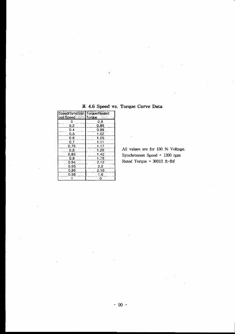
3E 4.6 Speed vs. Torque Curve Data
All values are for 100 % Voltage.
Synchronous Speed = 1200 rpm
Rated Torque = 30013 ft-lbf
-90-
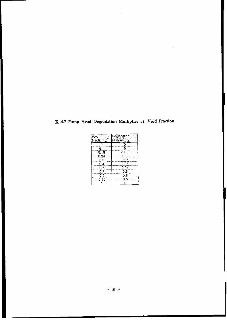
X 4.7 Pump Head DegradationMultipliervs. Void Fraction
Void Degradation
Fraction(a) IvlMiplier(rm)
.-t ..,,,.,,,,. ,,, .,,, .,.,,,,00“__. ...__..__ ———
._o.15 0.05
.. 9zfl_ ._.. - __.L8._..,-..–:._.. ...Q&3___.— .0.96 _
_..-.-!M-... 0.98097....0.6 .... .. . . ..?........ ..
.0,8,,,,...,.,....,-.,,,,,,,,,.0,.9,,-,,,,,,..........0.9............. ............ ......Q.-B.... . .
... ... ..0.96... ...... ........... .......0...?..... ~~1 0
-91-
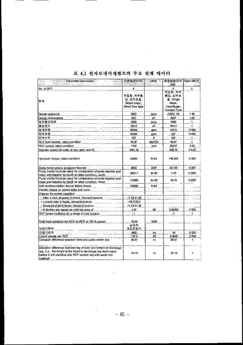
SL-L’L,L -RCS fluiddensity, rated concfificmRCP speed rated condition—— .. ..J”_%ecific Srx?ed(in units of mm, gpm, and ft)——-- . .i-tycfraulictorque, rated conditionBrake horse power at design frowratePurrwinertia (include value for ctinationGDUIYPinmellerand rrotcxand irrceller byi~.cl!) .at,.rated..c.qditi.orl,.W.!w . .. . . .. .. .. .Pumpinertia (include value for combinationoPUmJirmeller and rmtor end irmeller byitaelfl,~ed ccrldition,I’llXor.K–factorsare based on cold leg area of —RCP torque nwllfpfiertor a range of void
l-----------:::------:-----------fraction—.—— .. “---------- .-..——.—..- _________xJ~q&q
—— .—.—.Liquidvolume @r RCP—.. “. .- . ..- . .Elevaticmdifferencebetween inlet and outletc~er” yle,.,,,-,-,_____–_–_._”,--.~,Elevaticn differencebetween top of weir endbottomof discharge leg, (I.e., the heightofthe liquidin discharge leg rwst reach beforeit will backflow into RCP suctionleg wilh
.KWf?w?!K?WN).......... . . .. . . . . .Minirrum total flow for bur purqx at the ratechead of W7R.. . ... ... ... ... . . . . .. . . . . . . .. . .,.Mexirrumtotal flow fm fourpurrTx at the~,at@,head of 337tj............. . .The afxdute value of tie slope of the pu~performancecurve(head vs. flow rate) at tierated flow of..5,@Q.w..,..,... .The rr=inum spread in PUnp head beiween.R?W.w.m. ?[.m.eIat9Ql.w...Qw,ww.QmQm.The rrinirrwmhead that the PUnp shallbecapableof normaloperationat the rated [W
71Z93*(P)
4
m. . . .. . . . .m
@
%45.. ............. . . .W5CKI—.854C0——
337——.—45.87
Ilw
442f .24
m
6533——
2915.7
115W
4.9t..—— . ..—
1-.-- ...-,.-.,.-
w..__—.__. .,122.9
S2.57-.—~-. ..—
24.75
341,Oxl
244,axl
2)
297
Era?
*
427—.t 337..——-.
~ fbrnrf13 45.87~ .-—-—
*b-ft2----”-1.03
. .
lb+ I 40.70
... .. ...1....—....-——-.-
fu? 0.02455..—-.--—. .. .. . . .
1—-—-.— . ..— .--...__m?-----.._.”A?”. -...
tu 0.W-5
in I 93.57—.,...-—.”—--—.-..-...
-d-l
4
~,,,_
m
?2?3
%4.5
412.5
427
237—.—4587
16829
442f .34——146.325
33.105
1.Cr3
40.76
0.0245—— ------
1
44.-.—-..-...0.664s
93.57
24.75
1720
3.5WN
.,.a
297
11. .—11——
UfW16@Uf33f47W
1
1——
1
1
1. ..- —e—.. -
1
1
1.. ...—.
1..—..——
1
1.. .
1
1
1. .
1
-92-
Hot Isothermal Condition
500
450
400
350
/
300
250
150
100
50
0
564.5 “F
. . . . . . . . . . . . . . . . . . . . . . . . . .. !-----------------------
. ..-. ------
. . . . . . . . . . . . . . .
. . . ..-. . . .
. .
.
. .
v . . . . . . . . . . .
. . . . . . . . . . . . . . .10-$Q2
. . . . . ------ --
. . . . . . . . . . . . . . . .
. . . . . . . . . ..-.
. . . . . . . . .
. . . . .
0 10 20 30 40 50 60 70 80 90 100 110 120 130 140 150 160
FlowRate, X 1000 gpm
z ~ 4.1 RCS Hydraulic Resistance Limits for UCN 3&4
Head (ft) vs. Flow Rate (X 1000 gpm)
-93-
500I
..,:. v:.:\...-.:..,:
.:.400 .,.
.,..,
1A pump-~Condition“..::
.:....1A pump-&Condition
300/ I
.....:.
FRCS Hydraulic Resistant e .,,.,
,. \- ~ pump max. limit .:,.
\.’..
200.>..
.....
/100
‘.’... ..‘.”... ..
0-0
z %14.2(a) RCP
50000 100000 150000
Flow Rate, gpm
Performance Curve of UCN 4 for 1A Pump
-94-
..
i=’
s-
500
400
300
200
100
....‘. .,
‘, ...‘. ‘..
‘,, ‘..,.,,/ ‘$ .,
IB pump-~ Condition
I
‘\ ‘..‘. ‘...
‘. ...‘. ‘.
.
‘. “.. )‘. ‘..,
‘,‘.
‘\‘.
Kcs , .Wara uftc ueaisra{ Ice
4 oumo max. limit
‘),RCS Hydraulic Resist
1 oum D min. limit
I1B pump-~ Condition
...
,.,,
*
‘. .,\‘. ..
‘. ‘.
‘. ‘...‘. ...
‘. “..‘., ‘...
o0 50000 100000 150000
Flow Rate, gpm
z%! 4.2(b) RCP Performance Curve of UCN 4 for lB Pump
-95-

500
400
300
e
= 200
100
0
.,.
>;::,/
‘.....‘...
2A pump-w Condition
.. .,... , /., .
,.. \...’.\
‘... \.. \.. .
3CS Hydraulic Resistan< e.....
..:.,1pump msx. limit ..,:.
\,
RCS Hydraulic Resis lance ........
1 oump min. limit. .
..,\,...
0 50000 100000 150000
Flow Rate, gpm
z% 4.2(c) RCP PerformanceCurve of UCN 4 for 2A Pump
-96-

500
400
300
~
i200
100
0
.. .
... .... .
20 pump-~ Condiiion
2B pump-hJQ Condition
?CS Hydraulic Resistant e.... .,
‘.1 mimo max. limit
\,
‘.RCS HydraulicResis ante ““.. .,
,.. .,1 oumvmin. limit
... .\
o 50000 100000 150000
Flow Rate, gpm
Z a 4.2(d) RCP Performance Curve of UCN 4 for 2B Pump
-97”
. . .
1. . .
Single phase ho ologous head
cuwes for UCN 3 4
4b\\\+0+\\
o ‘\\ ‘\O\‘\+‘\.\+
‘b \‘o.&
“~-m-g.m-=-,.m“% -m.
“%W‘V3 d
-X-X.1 -J’~‘A-A-A.A_A-A~/d
J “?O/I /r /“
(
%K-%-x-~-
—m—HAN
—o— HVN
—A— HAT
—v— HVT
-o- HAD
—+— HVD
—x— HAR
—x— HVR
-1.0 -0.5 0.0 0.5 1.0
AIV or VIA
Normal Pump (’CL +N) : HAN, ~
Energy Dissipation (-~ +N) : HAD, HVD
Normal Turbin (-Q, -N) : HAT, HVT
Reverse Pump (+Q, -N) : HAR, HVR
~~ 4.3(a) Homologous Head Graph for UCN 3&4 Reactor Coolant
Pumps
-98-
.
3’
2
1
0
‘>iiiLo -1
‘mZ
-2
-3
-4
-5
Single phas
+\ curves for U‘\+’+\+
O\ ‘+\+o\. ‘+,+
‘o\ ‘+.0,
0‘O.O
omologous torque
i 3&4{
“-vb■-du+p-=-=;v’I
‘y:w -/0
e .@ =
d/AA=-
AA,
/*p
I
-1.0 -0.5 0.0 0.5 1.0
AIV or VIA
Normal Pump (+Q, +N) , BAN, BVN
Energy Dissipation (-Q +N) : BAD, BVD
Normal Turbin (-Q, -N) : BAT, BVT
Reverse Pump (+Q -N) : BAR, BVR
—m— BAN
—o— BVN
—A— BAT
—v— BVT
-o- BAD
—+— BVD
—x— BAR
—x— BVR
= ~ 4.3(b) Homologous Torque Graph for UCN 3&4 Reactor Coolant
Pumps
-9!3-
4.5
4.0r
Yo
: 3.5
‘z “
3.0t-
+
\e —--’---m
m—————E /0’
,/ ●
-10 0 10 20 30 40 50 60 70
QIN (gpm/rpm)
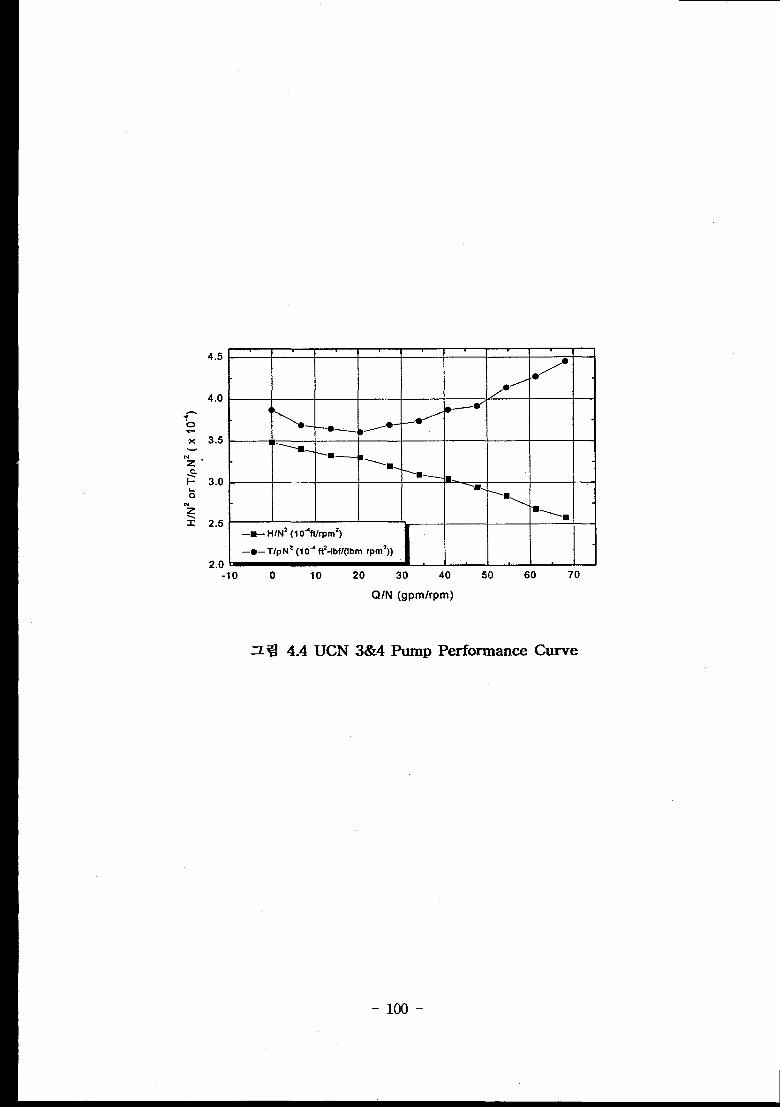
z ~ 4.4 UCN 3&4 Pump Performance Curve
-1oo-

2,5
2.0
0.0
Speed Torque Curve
All values are for 100% voltage
Synchronous Speed = 1200rpm
Rated Torque = 30013 ft-lbf
w-”/-’
_-.---m-= _-——m—.——————=
\
, I 1 I 4 1
0.0 0.2 0.4 0.6 0.8 1.0
Speed/Synchronous Speed
= w 4.5 Speed vs. Torque
- 101-
Curve
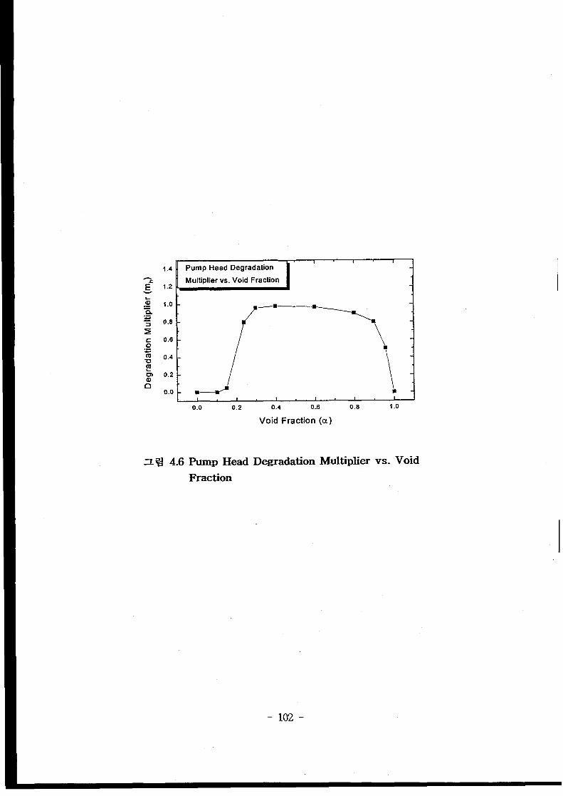
1 1 I1.4 Pump Head Degradation
-s Multiplier vs. Void Fractiong 1.2 ~
I 1 I I t 1 [ I0.0 0.2 0.4 0.6 0.8 1.0
Void Fraction (a)
tip Head
Fraction
DegradationMultiplier vs. Void
-102-
5Z4F.
-103-
-1o4-
IET-RE-DD3, %~%a~l-q $!3742,
Document Collectif, Equipe
Description,” SETh/LES/90-97.
q SEmj
BETHSY, 1990, “BETHSY General
EG&G IDAHO, INC., 1979, “System Design Description for the MOD-3
SEMISCALE System,” Contract EY-76-C-07-1570.
Felicione, F. S., 1975, “LOI?I’ primary coolant pump separate-effects
tests,” ANCR-1187, Aerojet Nuclear Co.
-105-
“Fluid System and Component Engineering Design Data for Plant Safety
Containment and Performance Analysis,” IET-FS-DD1, %}%% x}= q?~,
q3Wm~fl.
Gill, A. B., “Power Plant Perforrnance~ Butterworths.
Gloudemans, J. R., 1989, “Multiloop Integral System Test (MIST) : Final
Report,” NUREG/CP-5395-Vol.7.
Hicks, T. G., 1957, “Pump Selection and Application,” First Edition,
McGraw-Hill Company.
Hydraulic Institute, 1975, “Hydraulic Institute Standards for Centrifugal,
Rotary and Reciprocating Pumps,” Thirteenth edition.
Karnath P. S., and Swift W. L., 1982, “Two-phase Performance of Scale
Models of a Primary Coolant Pump,” Final Report, EPRI-NP--2578.
Larson, T. K., 1987, “An Investigation of Integral Facility Scaling and
Data Relation Methods (Integral System Test Program),”
NuREG/cR-4531.
Loomis, G. C., 1975, “Intact Loop Pump Performance during the
Serniscale MOD-1 Isothermal Test Series,” ANCR-1240, Aerojet Nuclear
Company.
Timothy, J. B., Thomas, K. L., Glen, E. M., and James, L. A., 1990,
“Scailing Analysis for a Savannah River Reactor Scaled Model Integral
System,” EGG-EAST--9382.
The ROSA N Group, 1984, “ROSA-IV Large Scale Test Facility (LSTF)
System Description,” JAERI-M-84-Z37.
-1o6-
White, F. M., 1986, “Fluid Mechanics,” Second Edition, McGraw-Hill
Company.
-107-
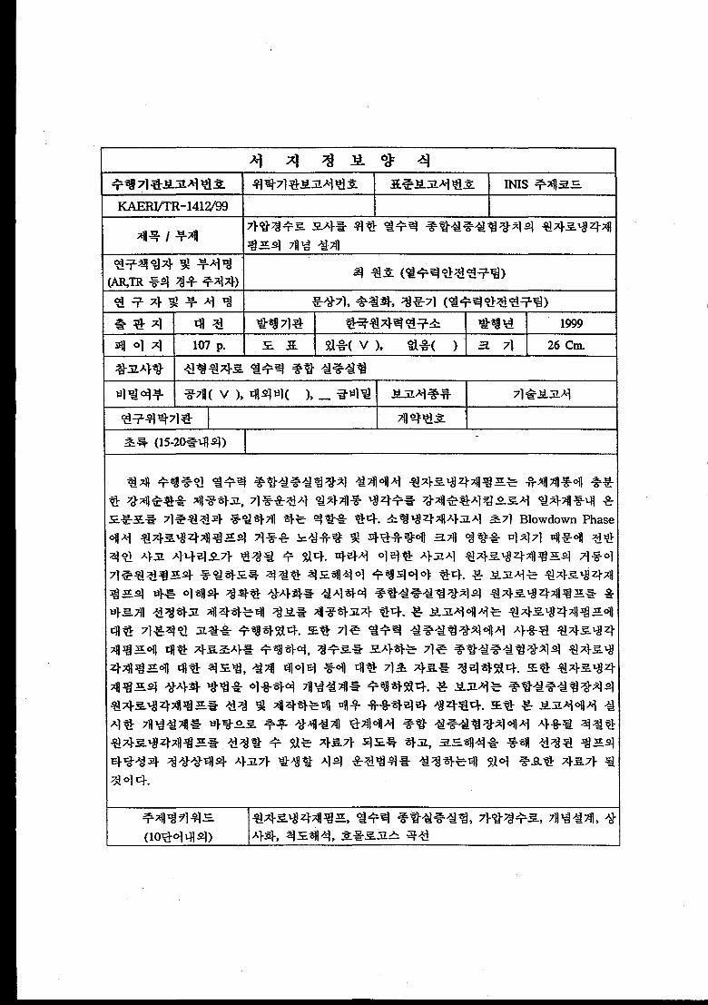
BIBLIC)GRAPHIC INFORMATION SHEET
Performingorg. sponsoringorg.
Report No,StamdardReport No.
ReportNo.INIS Subject Code
~-1412/99
Title / SubtitleConceptual Design of Reactor Coolant Pump of Integral Test Facility
for Siulating PWR
Main AuthorWon Ho Choi (ThermalHydraulic Safety ResearchTeam)
and Department
Researcherand Sang Ki MOOUChul Hwa Song, Moon Ki Chung
Department (Thermal HydraulicSafety Research Team)
PublicationTaejon Publisher
Publication
Place Date1999
Page 107 p. Ill. & Tab. Yes(V), No ( ) Size 26 Cm.
Note
classified Open( V ), Restricted ),_ class Document
Report Type TR
sponsoring org. ContractNo.
Abstract(15-20 Lines)
In the design of integral test facility currently carried out in KAERI, the reactor coolant
pump provides sufficient forced flow to primary coolant system and provides the same
temperature distributions in the primary system to the reference plant. At the initial
blowdown phase of small break LOCA, the behavior of the reactor coolant pump can affect
the core flow and break flow, and thus can change overall accident scenario. Therefore,
proper scaling analysis should be performed to correctly simulate the reference reactor
coolant pump. This report presents the scaling analysis result and provides design data fox
reactor coolant pump of integral test facility. This report summarizes basic inforrnations
about reactor coolant Pump. Also, this report includes the parameters of general reactor
coolant pump and the scaling methods for reactor coolant pump used in conventional
integrel test loops. Fhmlly, the conceptual design of reactor coolant Pump is performed using
scaling laws. This report is thought to be very useful for the design and selection of the
reactor coolant pump of integral test loop, and is expected to be used as a guide at the
detailed design of reactor coolant pump to simulate the operational and accidental transients
to be occurred in the integral test looP in view of thermal hydraulics.
Subject Keywords Reactor Coolant Pump, Integral Test Loop, PWR, Conceptual Design,
(About 10 WOrdS) Similarity,Scaling,Flow Characteristics,Homologous Curves