Embed Size (px)
Citation preview
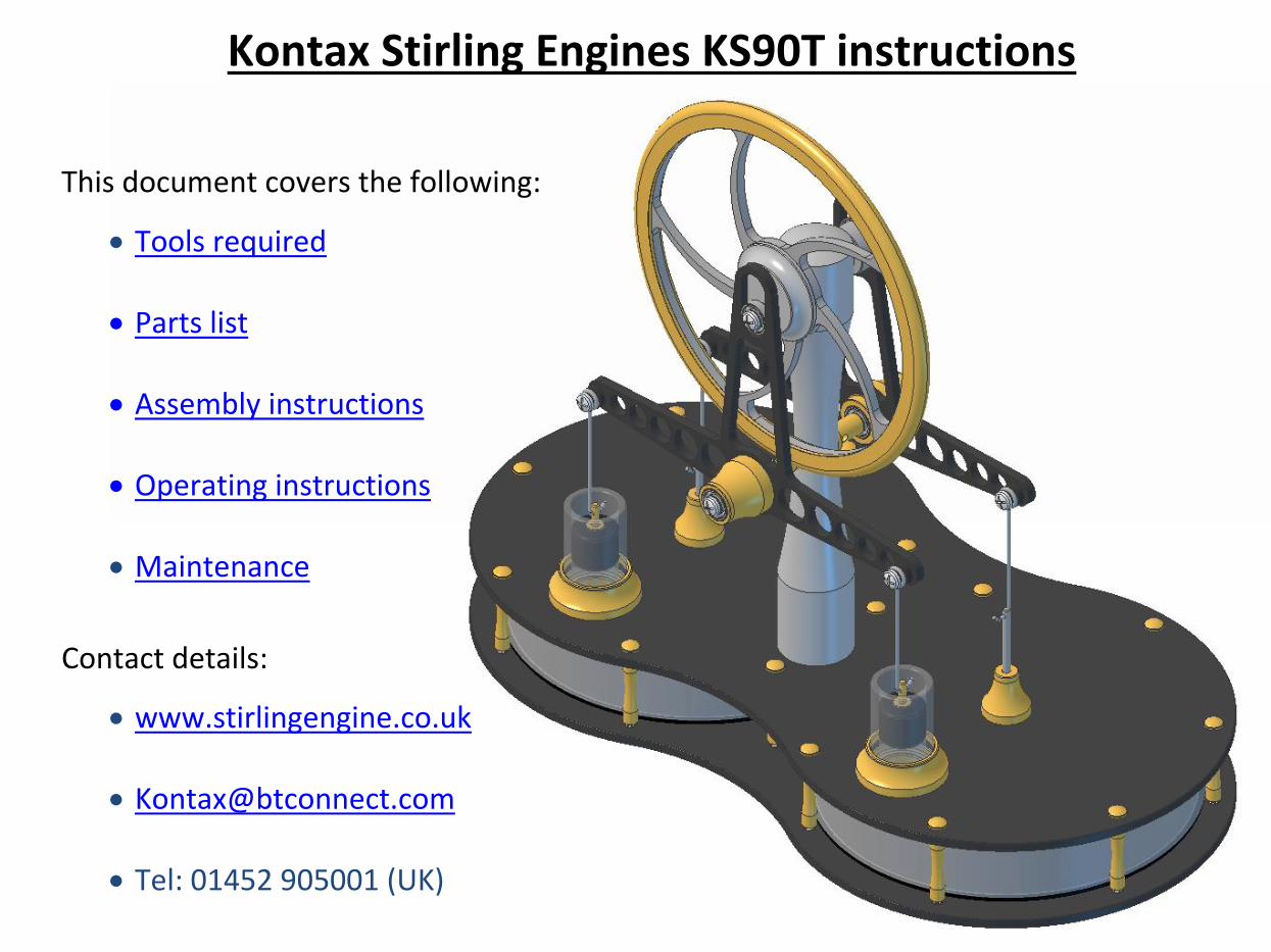
Kontax Stirling Engines KS90T instructions
This document covers the following:
Tools required
Parts list
Assembly instructions
Operating instructions
Maintenance
Contact details:
www.stirlingengine.co.uk
Tel: 01452 905001 (UK)
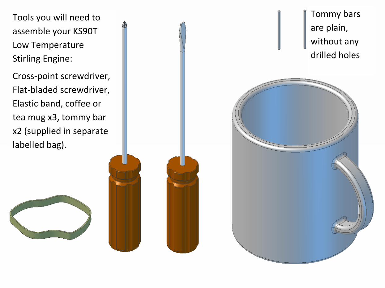
Tools you will need to
assemble your KS90T
Low Temperature
Stirling Engine:
Cross-point screwdriver,
Flat-bladed screwdriver,
Elastic band, coffee or
tea mug x3, tommy bar
x2 (supplied in separate
labelled bag).
Tommy bars
are plain,
without any
drilled holes
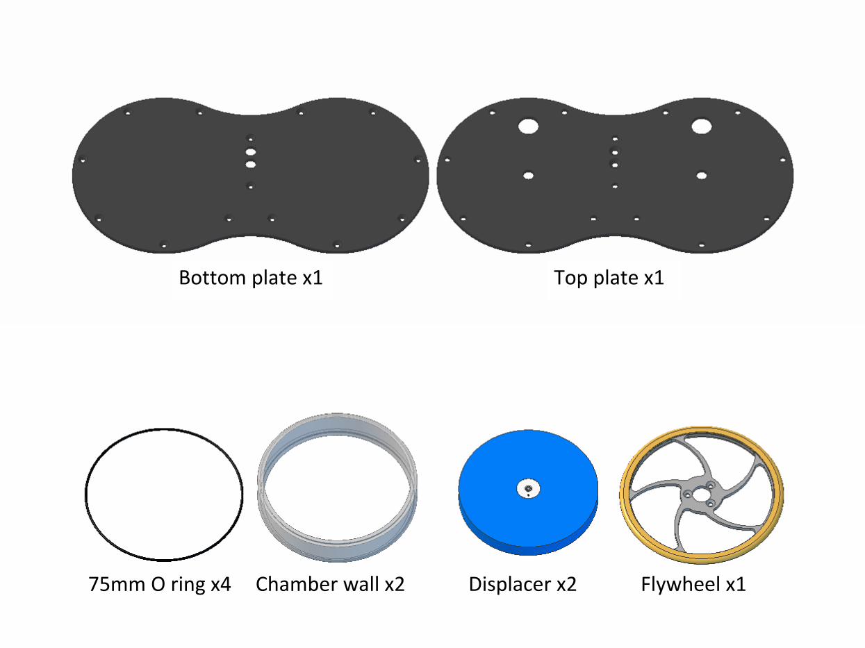
Bottom plate x1 Top plate x1
75mm O ring x4 Chamber wall x2 Displacer x2 Flywheel x1
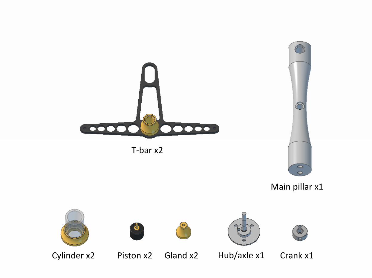
Cylinder x2 Piston x2 Gland x2 Hub/axle x1 Crank x1
T-bar x2
Main pillar x1
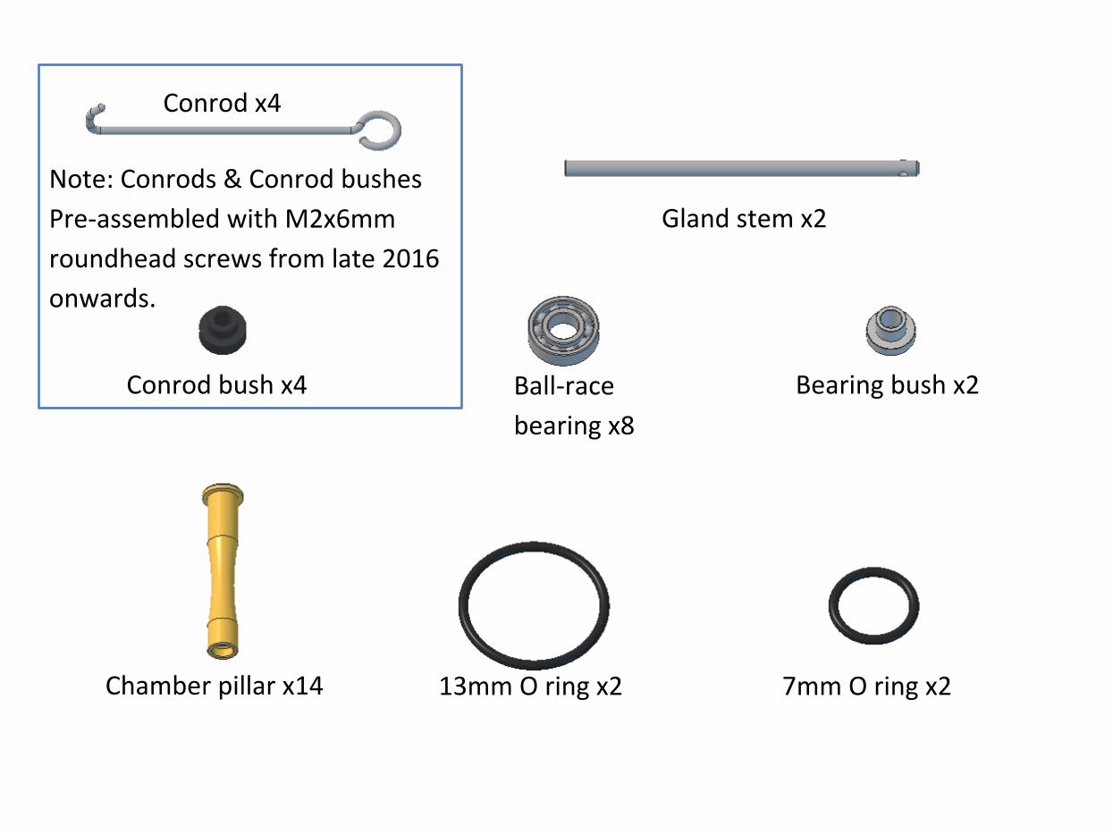
Conrod x4
Gland stem x2
Conrod bush x4 Ball-race
bearing x8
Bearing bush x2
Chamber pillar x14 13mm O ring x2 7mm O ring x2
Note: Conrods & Conrod bushes
Pre-assembled with M2x6mm
roundhead screws from late 2016
onwards.
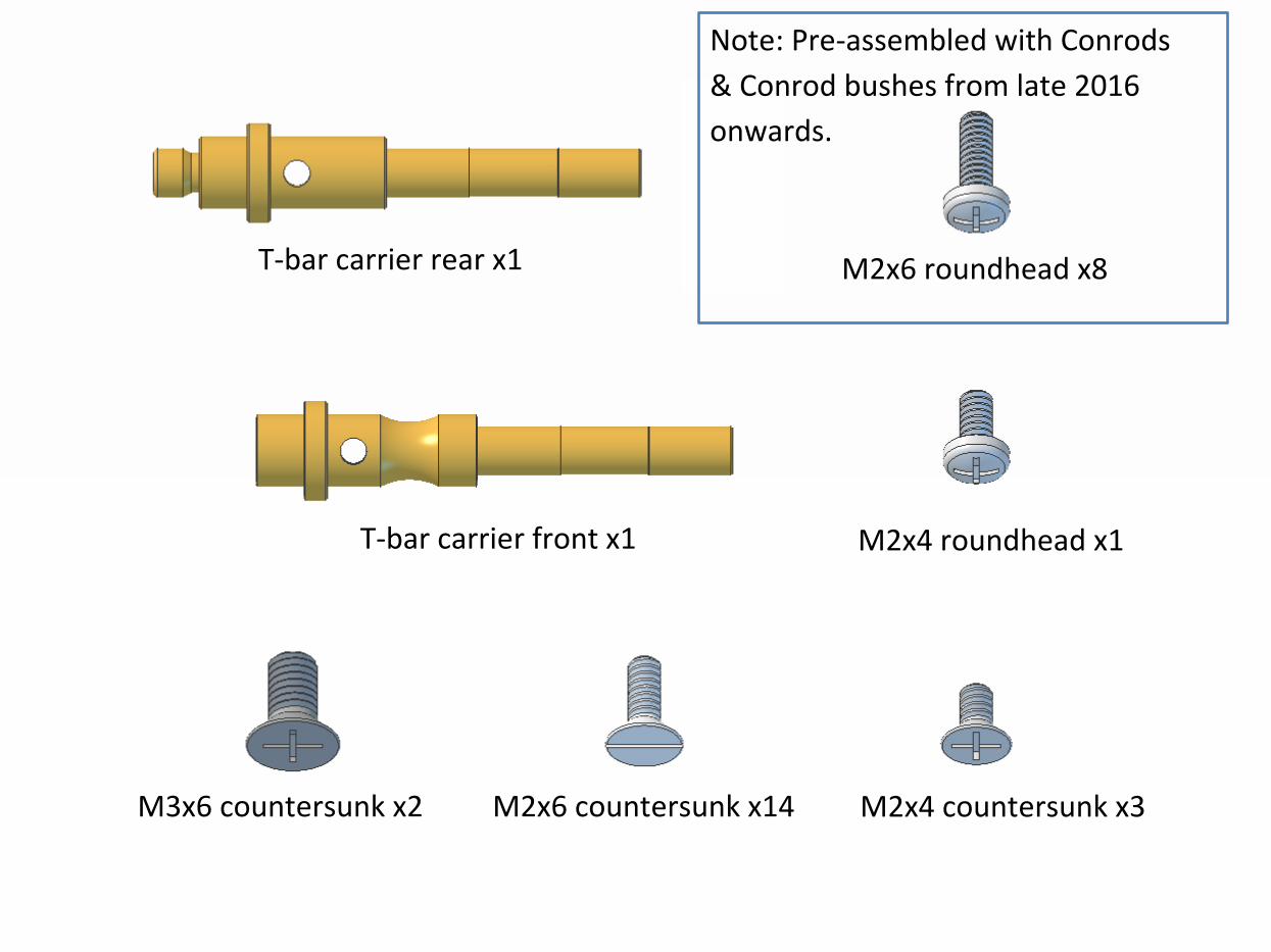
T-bar carrier rear x1
T-bar carrier front x1
M2x6 roundhead x8
M2x4 roundhead x1
M2x4 countersunk x3 M2x6 countersunk x14 M3x6 countersunk x2
Note: Pre-assembled with Conrods
& Conrod bushes from late 2016
onwards.
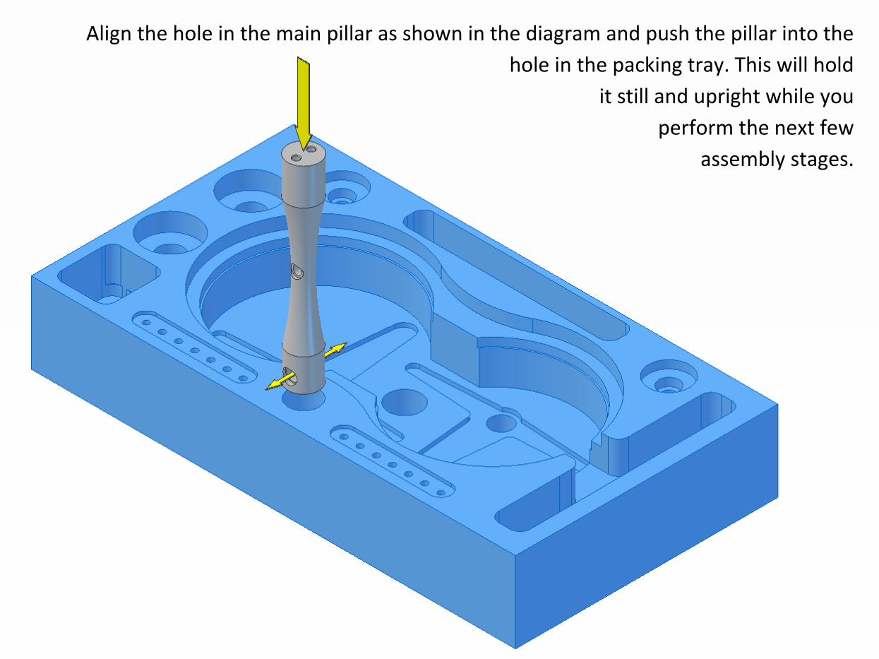
Align the hole in the main pillar as shown in the diagram and push the pillar into the
hole in the packing tray. This will hold
it still and upright while you
perform the next few
assembly stages.
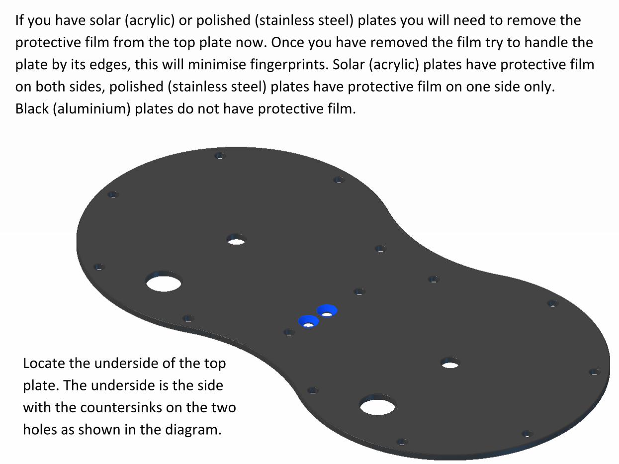
Locate the underside of the top
plate. The underside is the side
with the countersinks on the two
holes as shown in the diagram.
If you have solar (acrylic) or polished (stainless steel) plates you will need to remove the
protective film from the top plate now. Once you have removed the film try to handle the
plate by its edges, this will minimise fingerprints. Solar (acrylic) plates have protective film
on both sides, polished (stainless steel) plates have protective film on one side only.
Black (aluminium) plates do not have protective film.
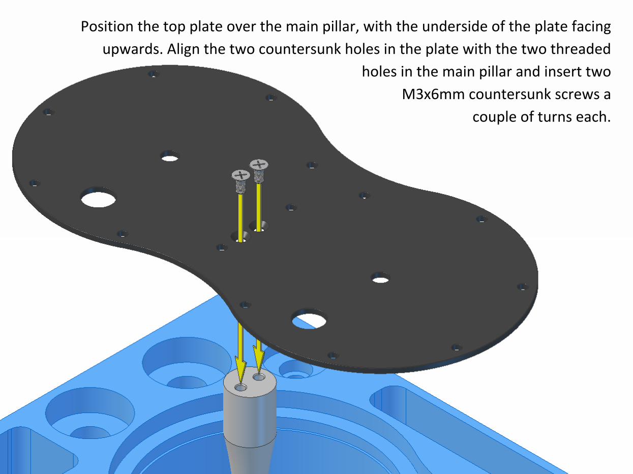
Position the top plate over the main pillar, with the underside of the plate facing
upwards. Align the two countersunk holes in the plate with the two threaded
holes in the main pillar and insert two
M3x6mm countersunk screws a
couple of turns each.
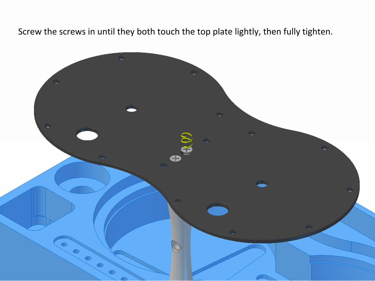
Screw the screws in until they both touch the top plate lightly, then fully tighten.
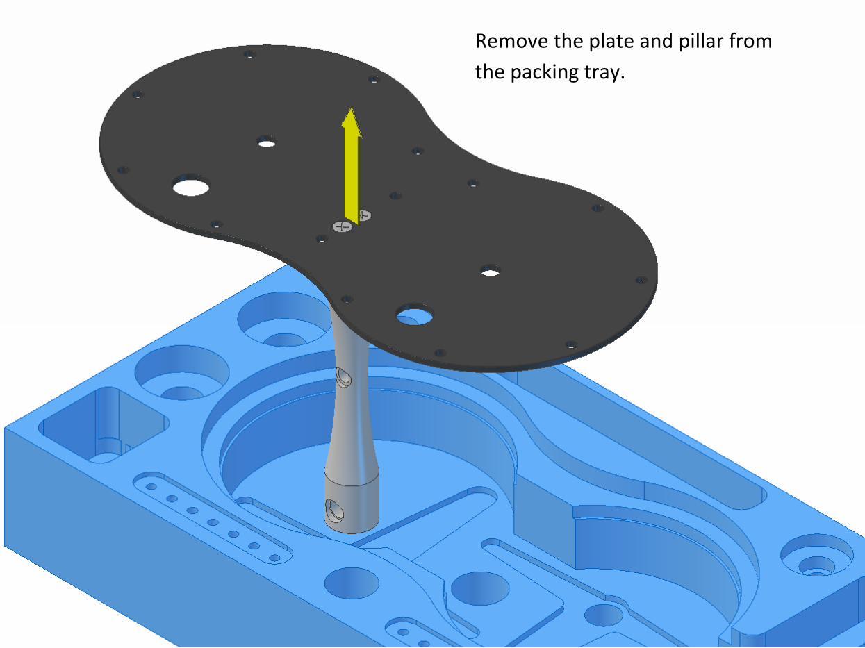
Remove the plate and pillar from
the packing tray.
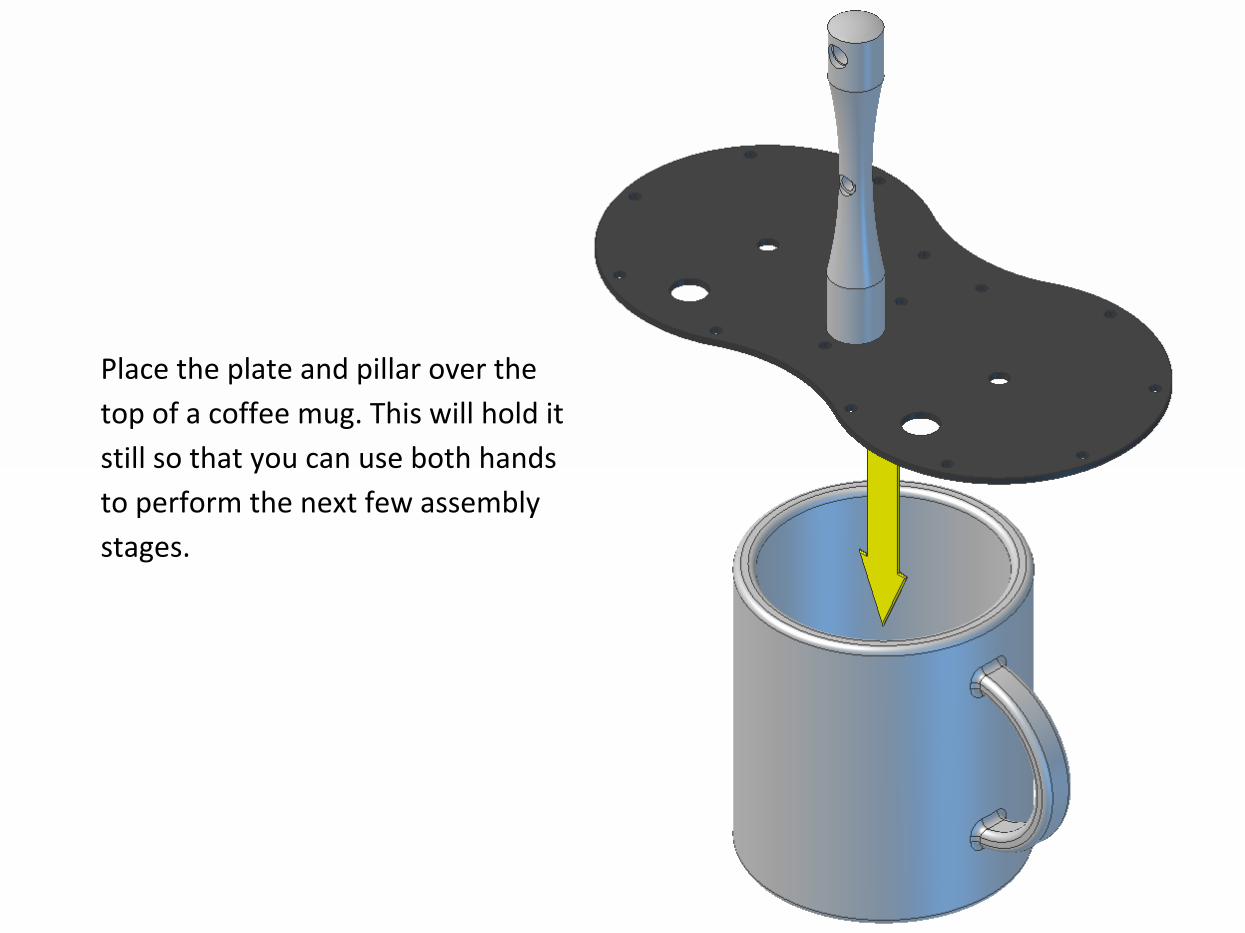
Place the plate and pillar over the
top of a coffee mug. This will hold it
still so that you can use both hands
to perform the next few assembly
stages.
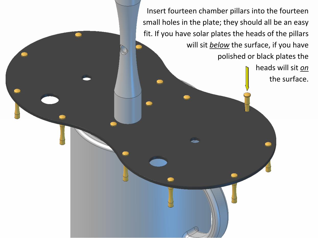
Insert fourteen chamber pillars into the fourteen
small holes in the plate; they should all be an easy
fit. If you have solar plates the heads of the pillars
will sit below the surface, if you have
polished or black plates the
heads will sit on
the surface.
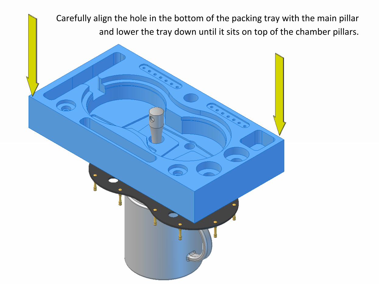
Carefully align the hole in the bottom of the packing tray with the main pillar
and lower the tray down until it sits on top of the chamber pillars.
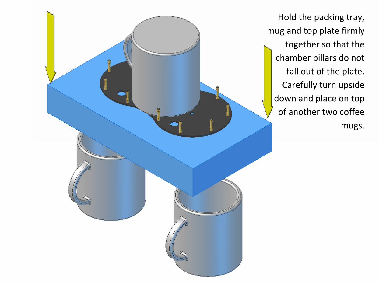
Hold the packing tray,
mug and top plate firmly
together so that the
chamber pillars do not
fall out of the plate.
Carefully turn upside
down and place on top
of another two coffee
mugs.
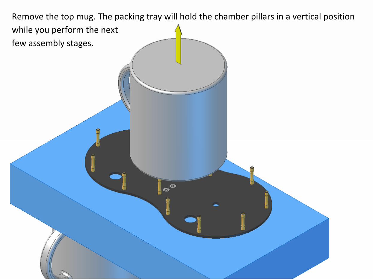
Remove the top mug. The packing tray will hold the chamber pillars in a vertical position
while you perform the next
few assembly stages.
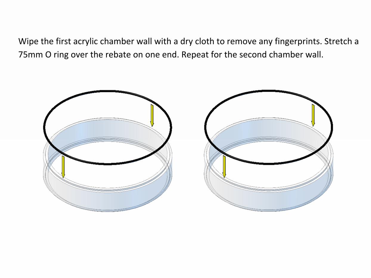
Wipe the first acrylic chamber wall with a dry cloth to remove any fingerprints. Stretch a
75mm O ring over the rebate on one end. Repeat for the second chamber wall.
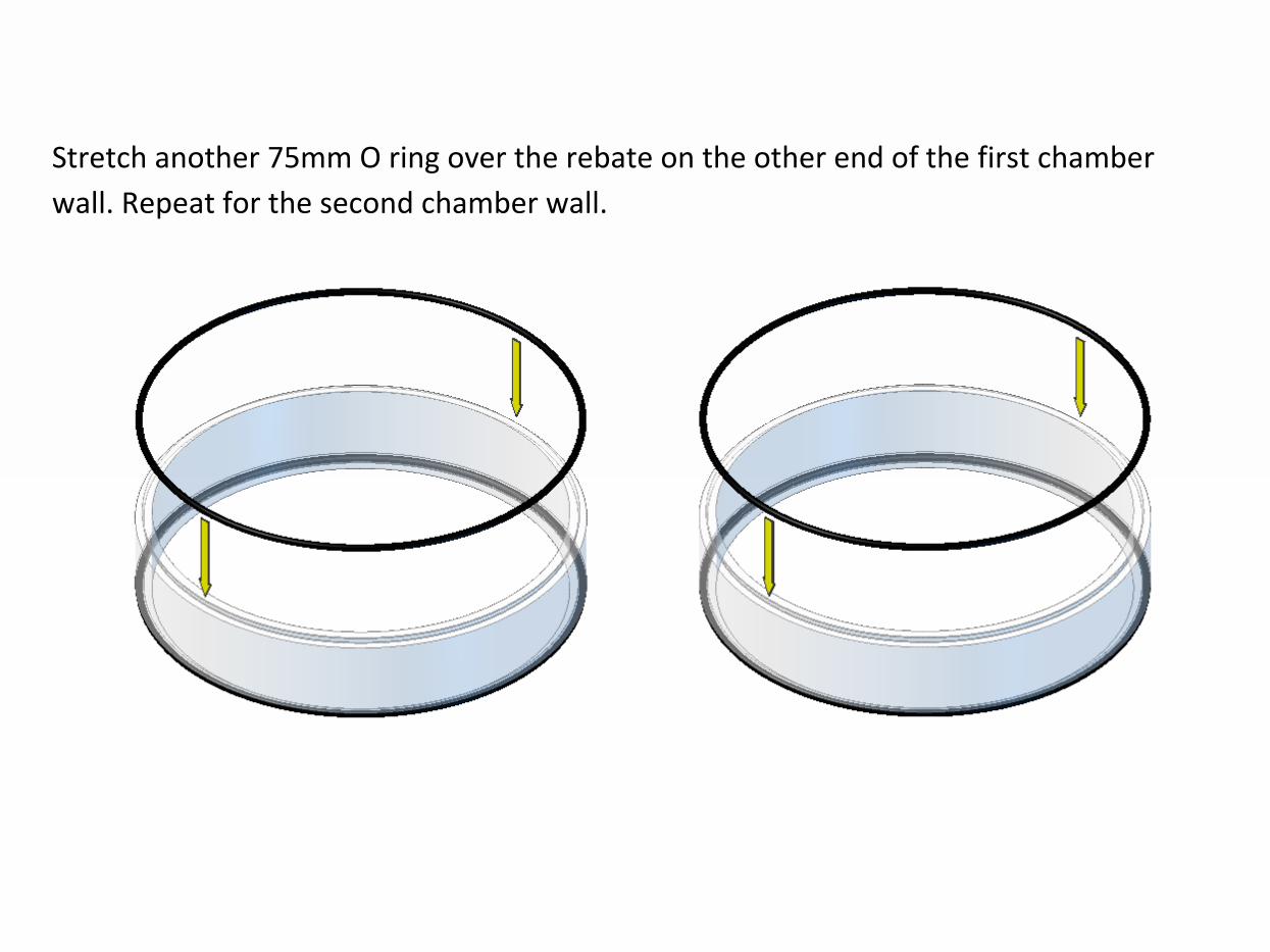
Stretch another 75mm O ring over the rebate on the other end of the first chamber
wall. Repeat for the second chamber wall.
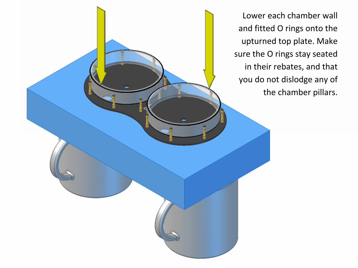
Lower each chamber wall
and fitted O rings onto the
upturned top plate. Make
sure the O rings stay seated
in their rebates, and that
you do not dislodge any of
the chamber pillars.

The top faces of the displacers have been marked with a coloured dot near their
centres.
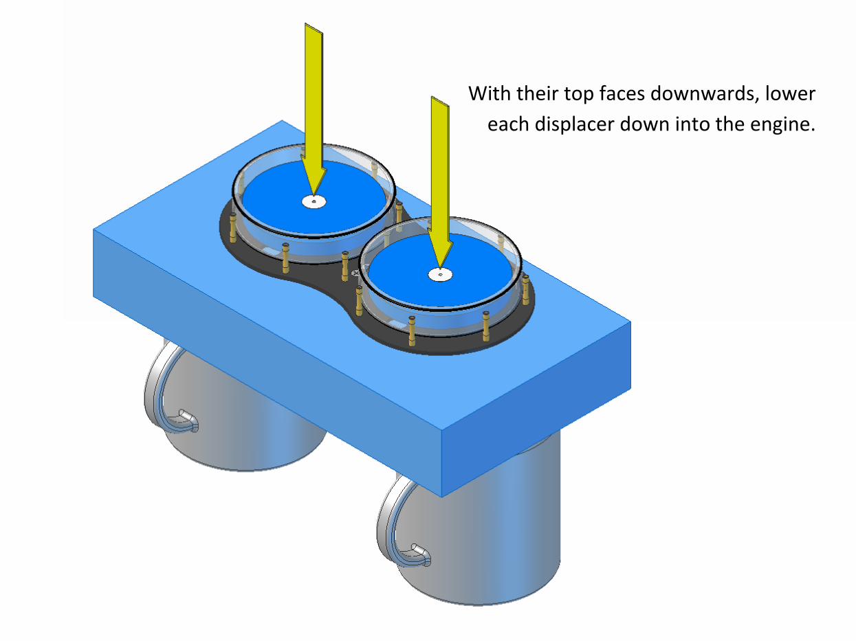
With their top faces downwards, lower
each displacer down into the engine.
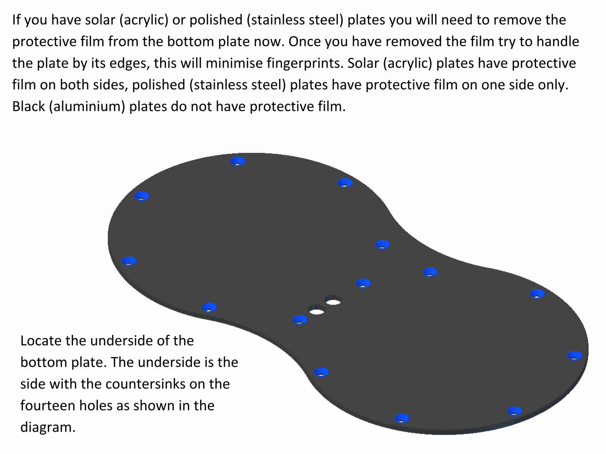
Locate the underside of the
bottom plate. The underside is the
side with the countersinks on the
fourteen holes as shown in the
diagram.
If you have solar (acrylic) or polished (stainless steel) plates you will need to remove the
protective film from the bottom plate now. Once you have removed the film try to handle
the plate by its edges, this will minimise fingerprints. Solar (acrylic) plates have protective
film on both sides, polished (stainless steel) plates have protective film on one side only.
Black (aluminium) plates do not have protective film.
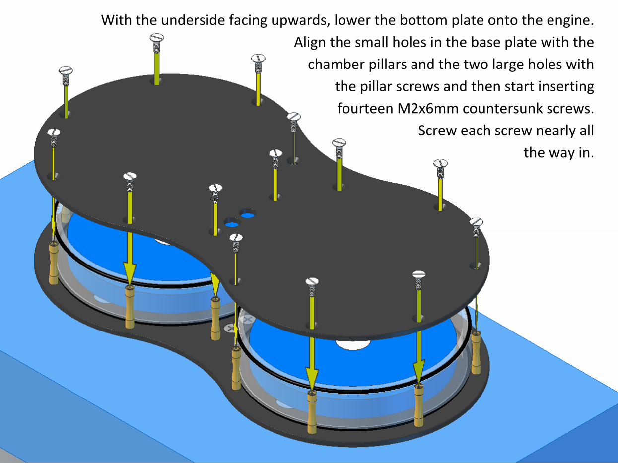
With the underside facing upwards, lower the bottom plate onto the engine.
Align the small holes in the base plate with the
chamber pillars and the two large holes with
the pillar screws and then start inserting
fourteen M2x6mm countersunk screws.
Screw each screw nearly all
the way in.
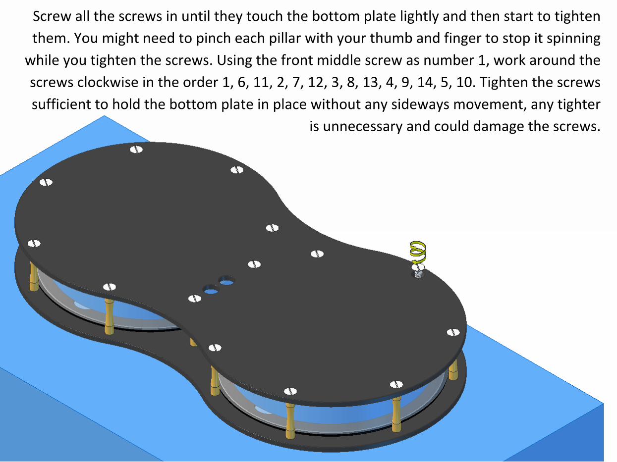
Screw all the screws in until they touch the bottom plate lightly and then start to tighten
them. You might need to pinch each pillar with your thumb and finger to stop it spinning
while you tighten the screws. Using the front middle screw as number 1, work around the
screws clockwise in the order 1, 6, 11, 2, 7, 12, 3, 8, 13, 4, 9, 14, 5, 10. Tighten the screws
sufficient to hold the bottom plate in place without any sideways movement, any tighter
is unnecessary and could damage the screws.
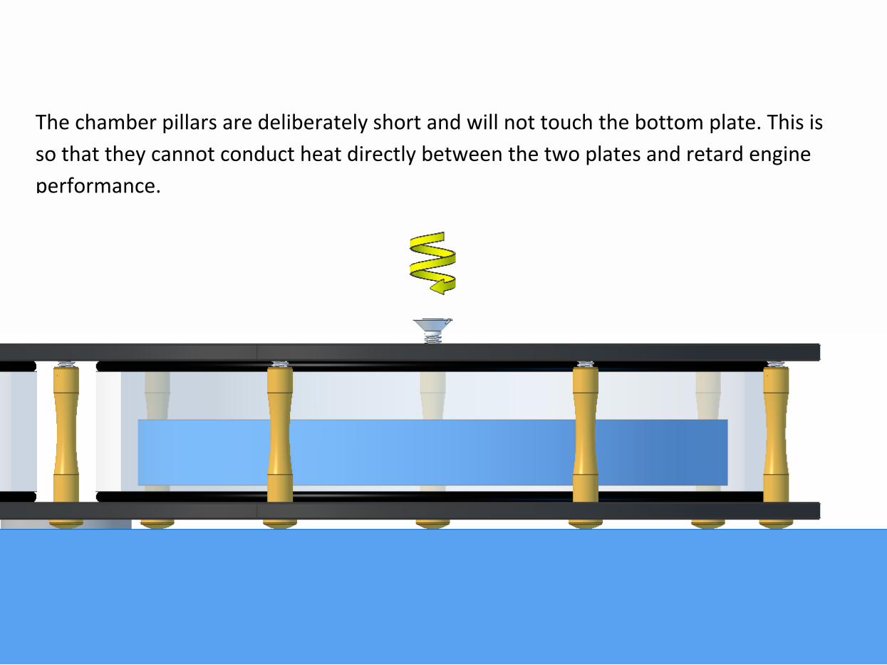
The chamber pillars are deliberately short and will not touch the bottom plate. This is
so that they cannot conduct heat directly between the two plates and retard engine
performance.
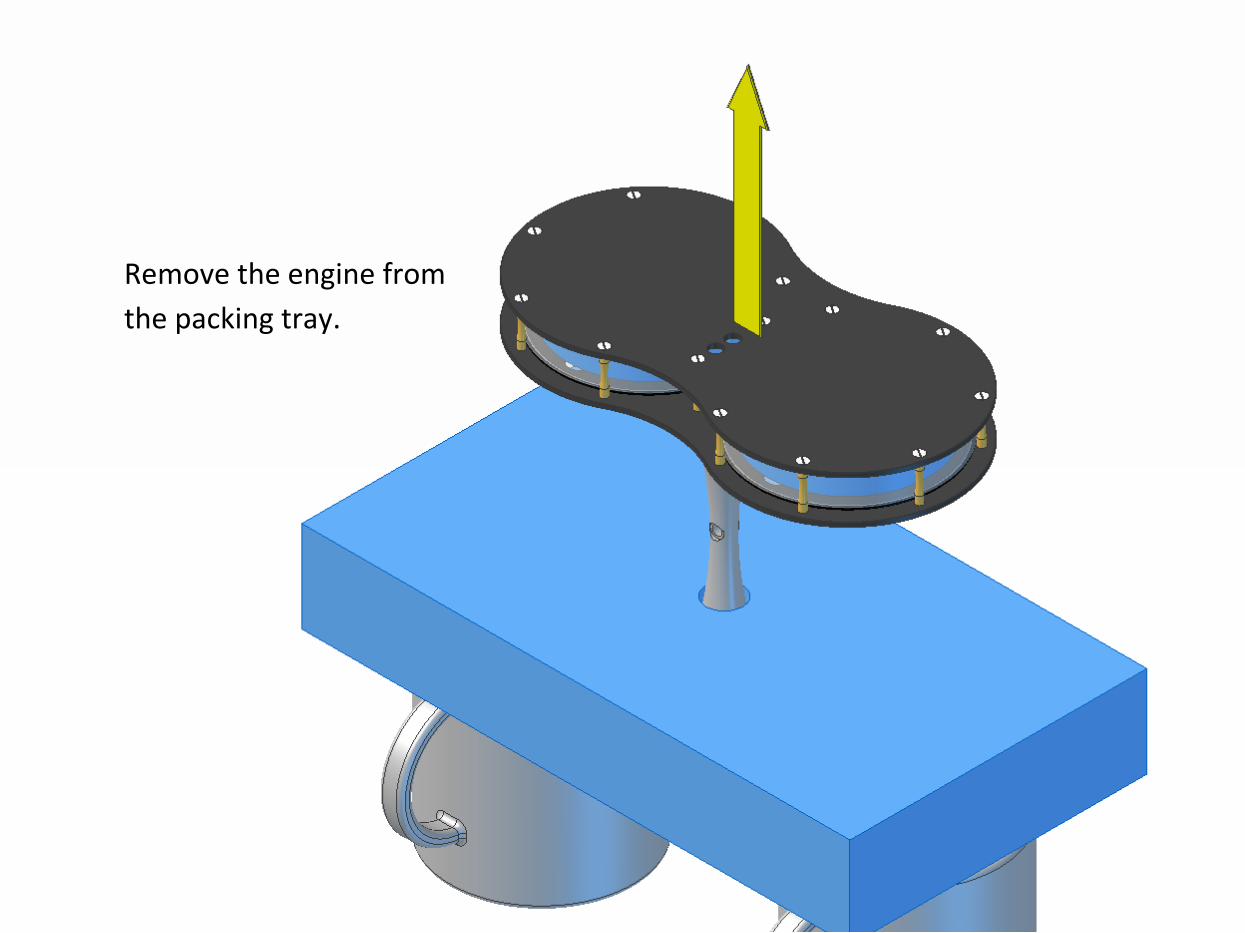
Remove the engine from
the packing tray.
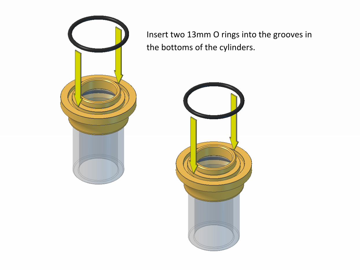
Insert two 13mm O rings into the grooves in
the bottoms of the cylinders.
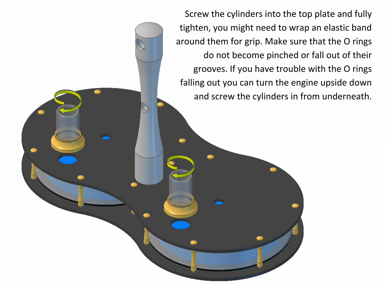
Screw the cylinders into the top plate and fully
tighten, you might need to wrap an elastic band
around them for grip. Make sure that the O rings
do not become pinched or fall out of their
grooves. If you have trouble with the O rings
falling out you can turn the engine upside down
and screw the cylinders in from underneath.
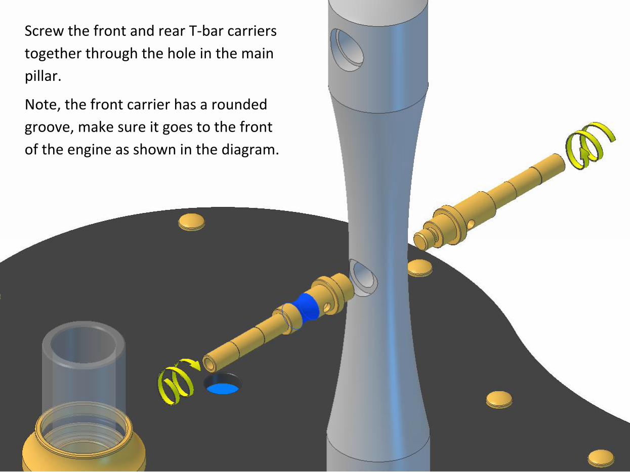
Screw the front and rear T-bar carriers
together through the hole in the main
pillar.
Note, the front carrier has a rounded
groove, make sure it goes to the front
of the engine as shown in the diagram.
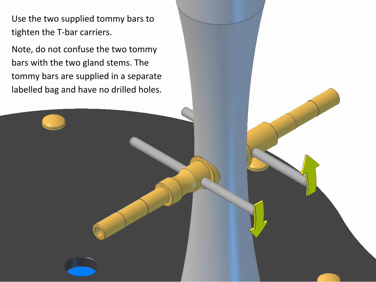
Use the two supplied tommy bars to
tighten the T-bar carriers.
Note, do not confuse the two tommy
bars with the two gland stems. The
tommy bars are supplied in a separate
labelled bag and have no drilled holes.
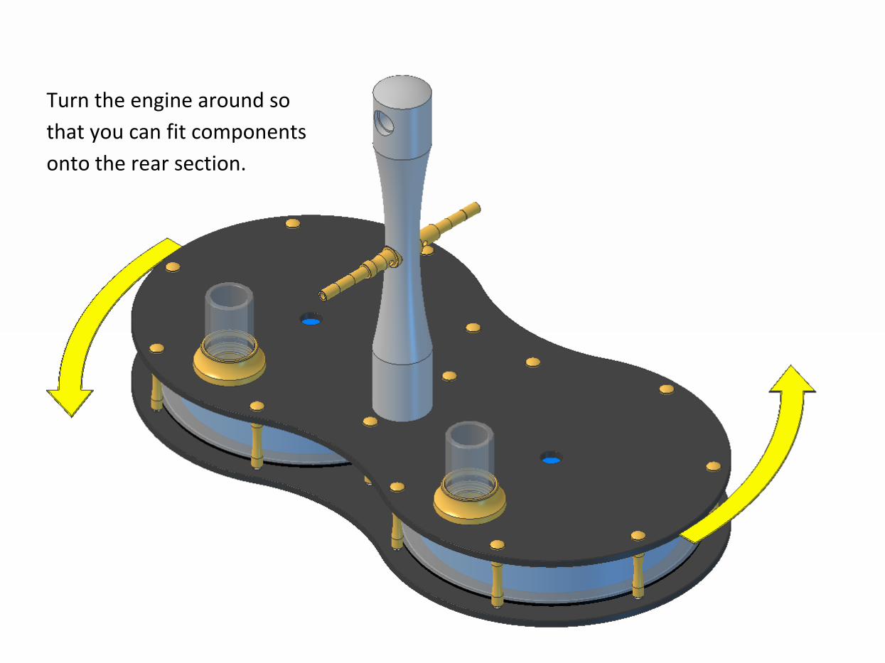
Turn the engine around so
that you can fit components
onto the rear section.
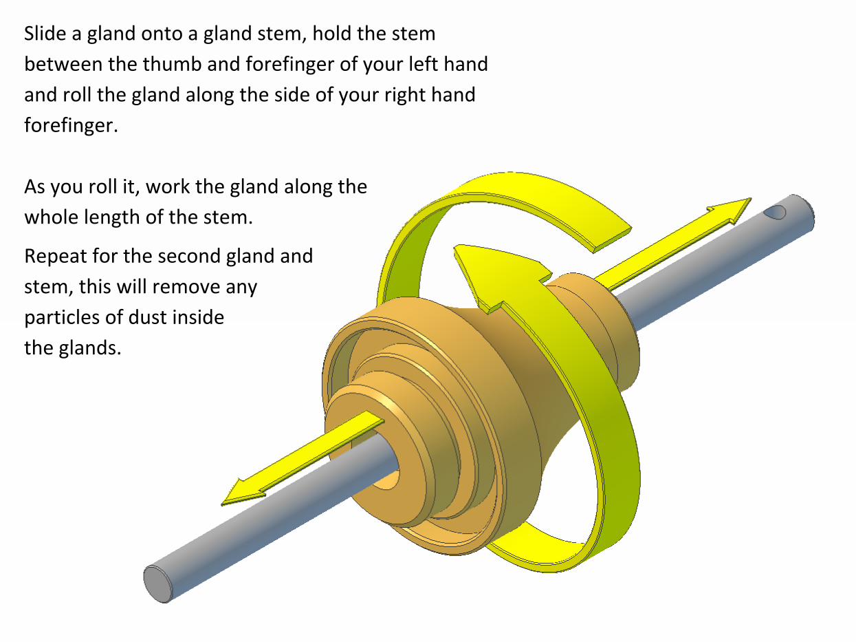
Slide a gland onto a gland stem, hold the stem
between the thumb and forefinger of your left hand
and roll the gland along the side of your right hand
forefinger.
As you roll it, work the gland along the
whole length of the stem.
Repeat for the second gland and
stem, this will remove any
particles of dust inside
the glands.
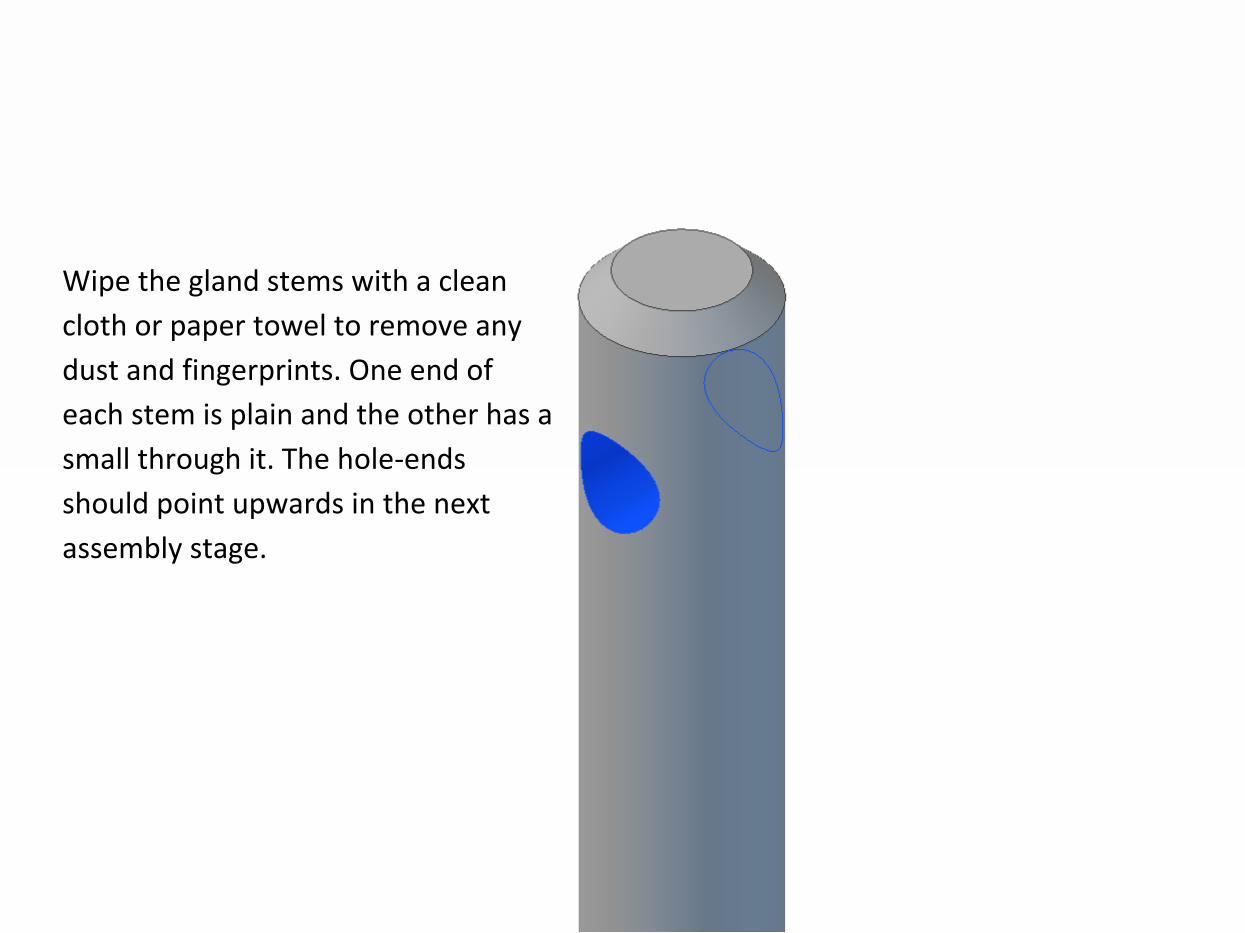
Wipe the gland stems with a clean
cloth or paper towel to remove any
dust and fingerprints. One end of
each stem is plain and the other has a
small through it. The hole-ends
should point upwards in the next
assembly stage.
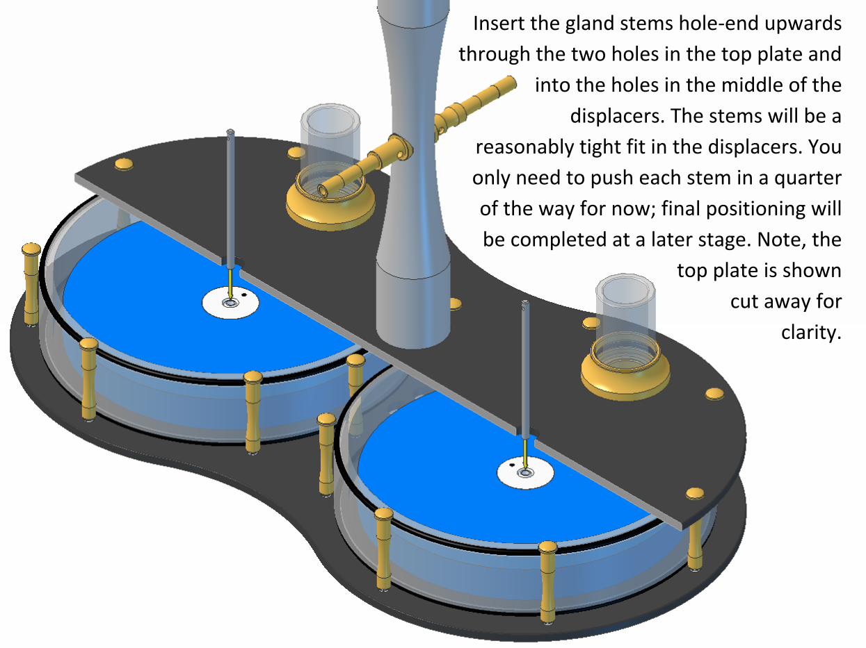
Insert the gland stems hole-end upwards
through the two holes in the top plate and
into the holes in the middle of the
displacers. The stems will be a
reasonably tight fit in the displacers. You
only need to push each stem in a quarter
of the way for now; final positioning will
be completed at a later stage. Note, the
top plate is shown
cut away for
clarity.
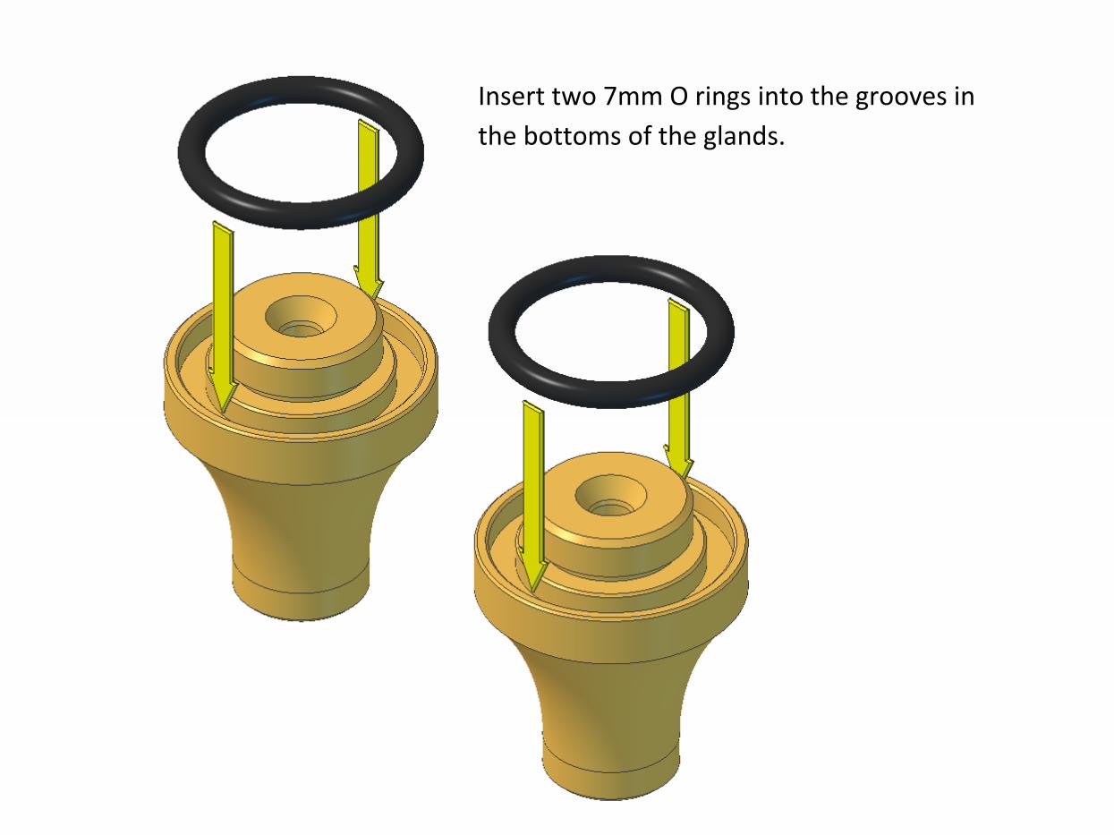
Insert two 7mm O rings into the grooves in
the bottoms of the glands.
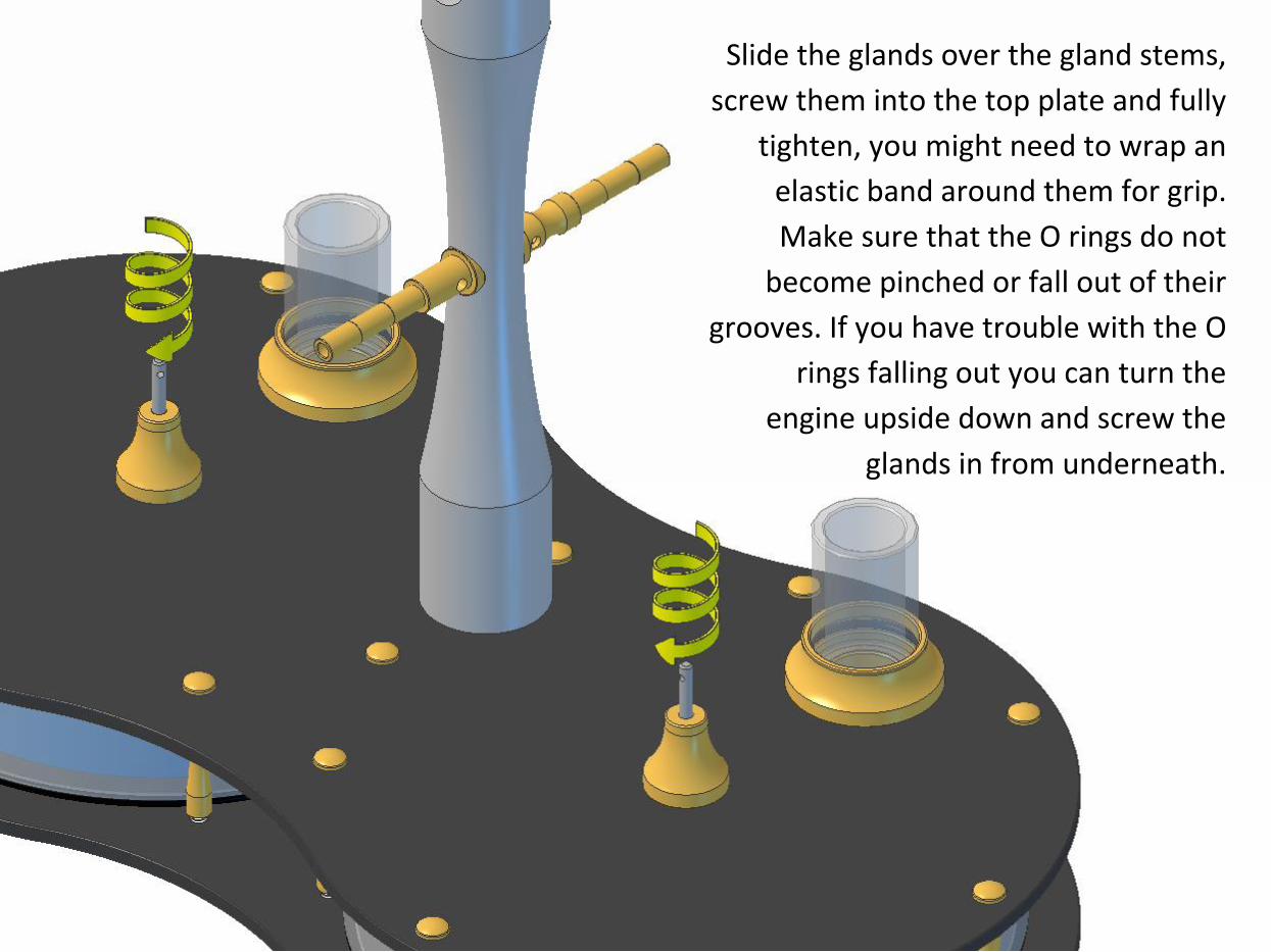
Slide the glands over the gland stems,
screw them into the top plate and fully
tighten, you might need to wrap an
elastic band around them for grip.
Make sure that the O rings do not
become pinched or fall out of their
grooves. If you have trouble with the O
rings falling out you can turn the
engine upside down and screw the
glands in from underneath.
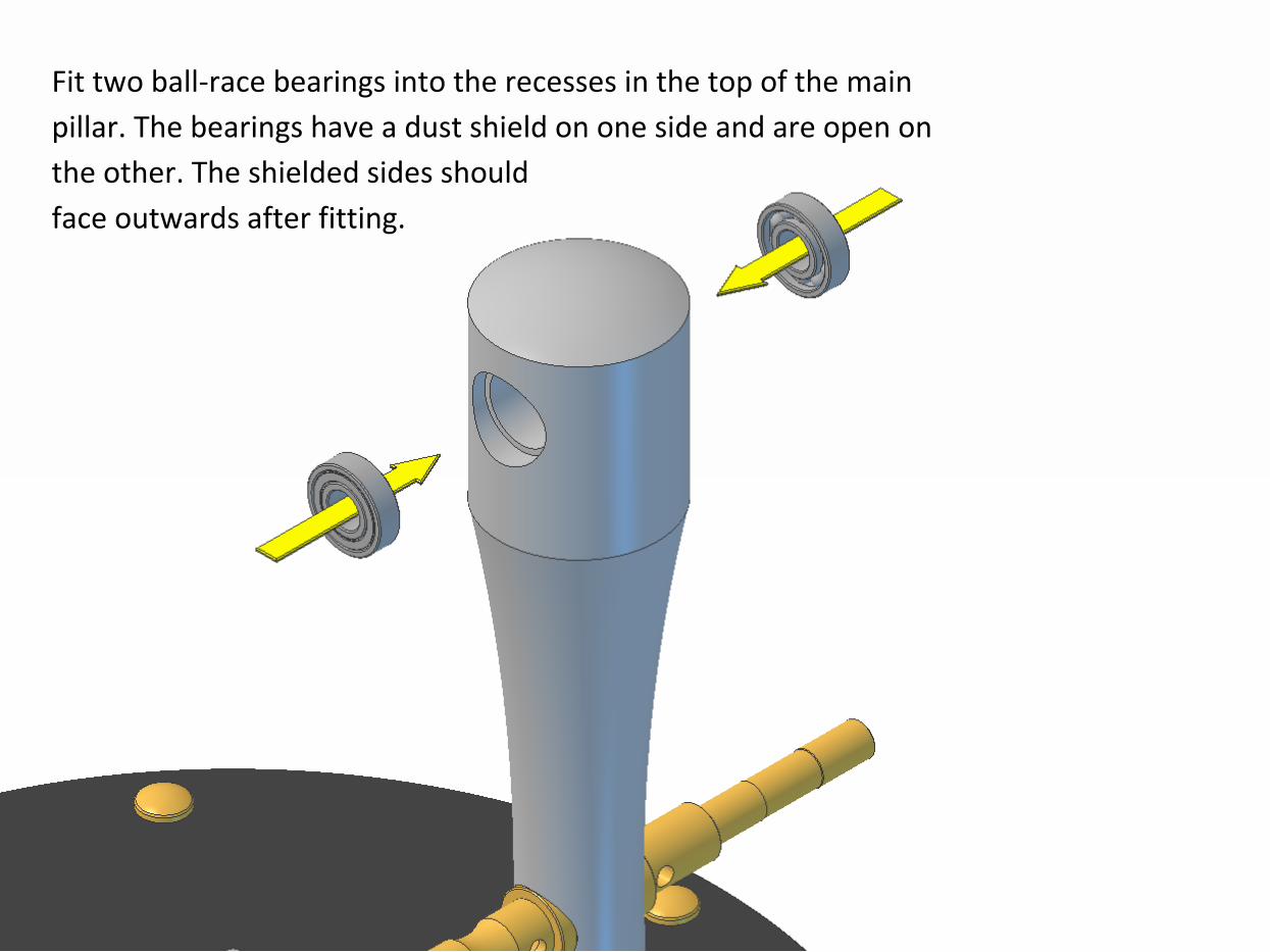
Fit two ball-race bearings into the recesses in the top of the main
pillar. The bearings have a dust shield on one side and are open on
the other. The shielded sides should
face outwards after fitting.
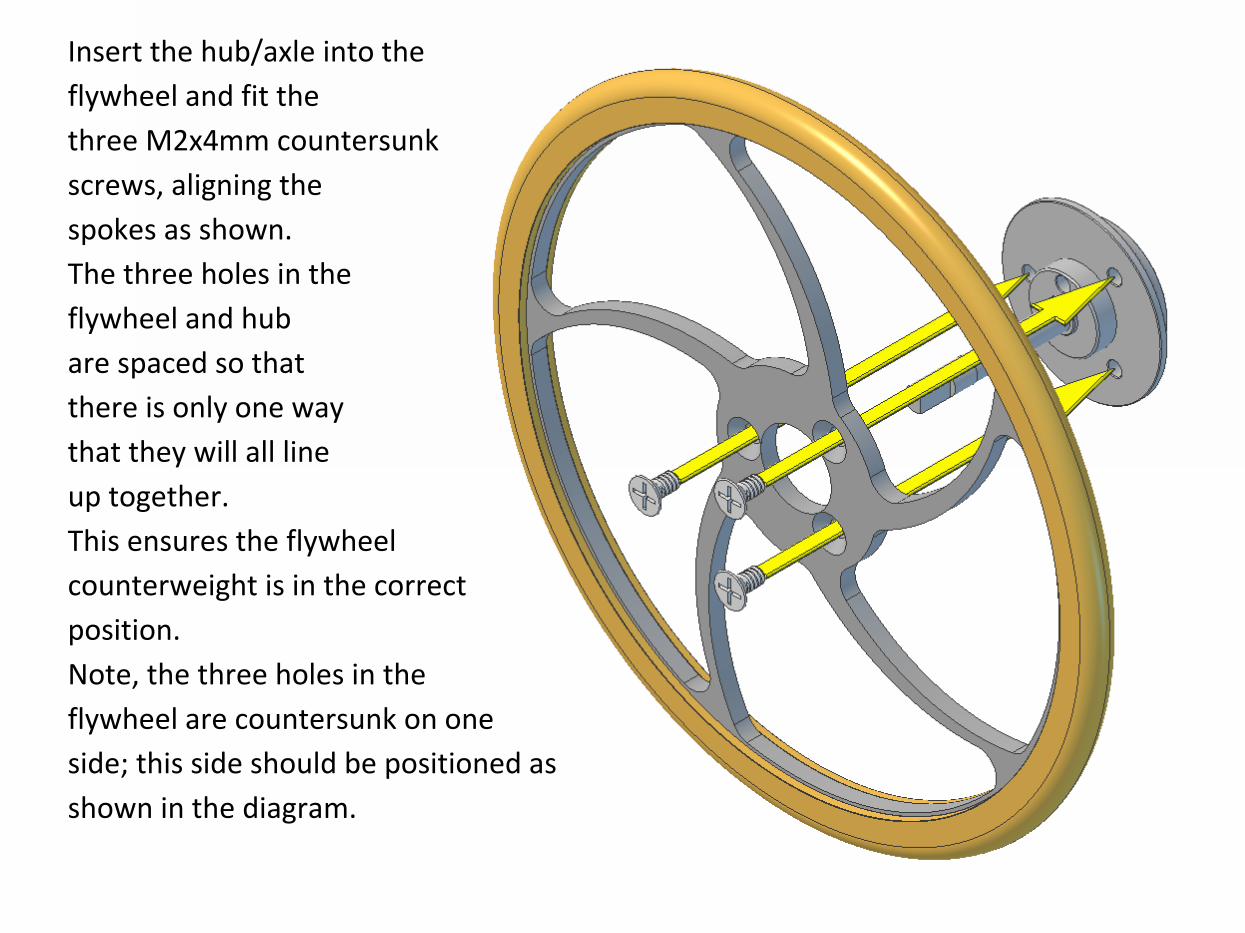
Insert the hub/axle into the
flywheel and fit the
three M2x4mm countersunk
screws, aligning the
spokes as shown.
The three holes in the
flywheel and hub
are spaced so that
there is only one way
that they will all line
up together.
This ensures the flywheel
counterweight is in the correct
position.
Note, the three holes in the
flywheel are countersunk on one
side; this side should be positioned as
shown in the diagram.
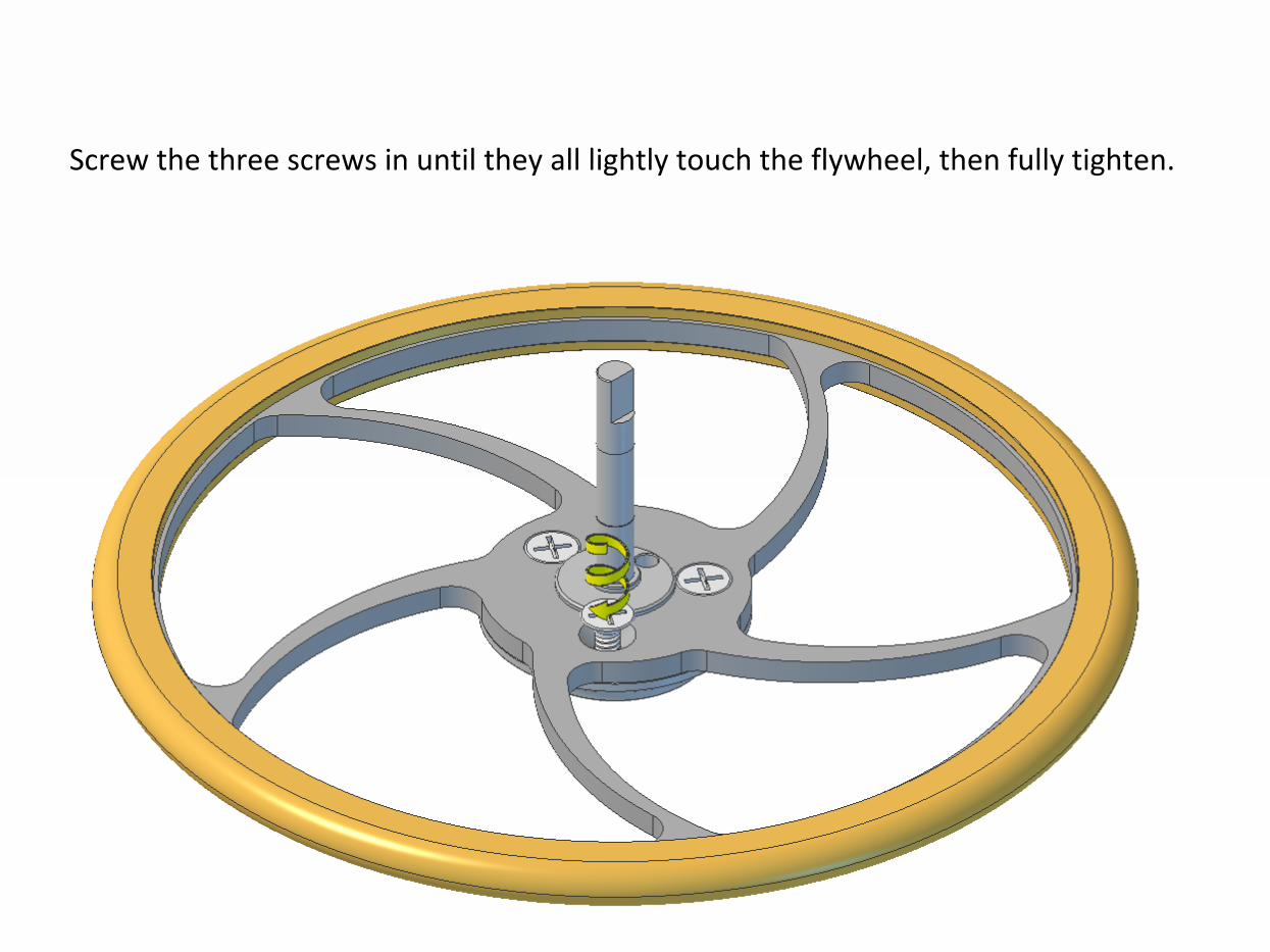
Screw the three screws in until they all lightly touch the flywheel, then fully tighten.
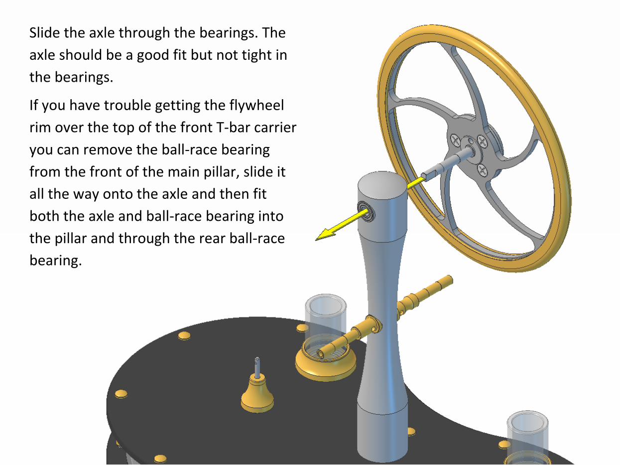
Slide the axle through the bearings. The
axle should be a good fit but not tight in
the bearings.
If you have trouble getting the flywheel
rim over the top of the front T-bar carrier
you can remove the ball-race bearing
from the front of the main pillar, slide it
all the way onto the axle and then fit
both the axle and ball-race bearing into
the pillar and through the rear ball-race
bearing.
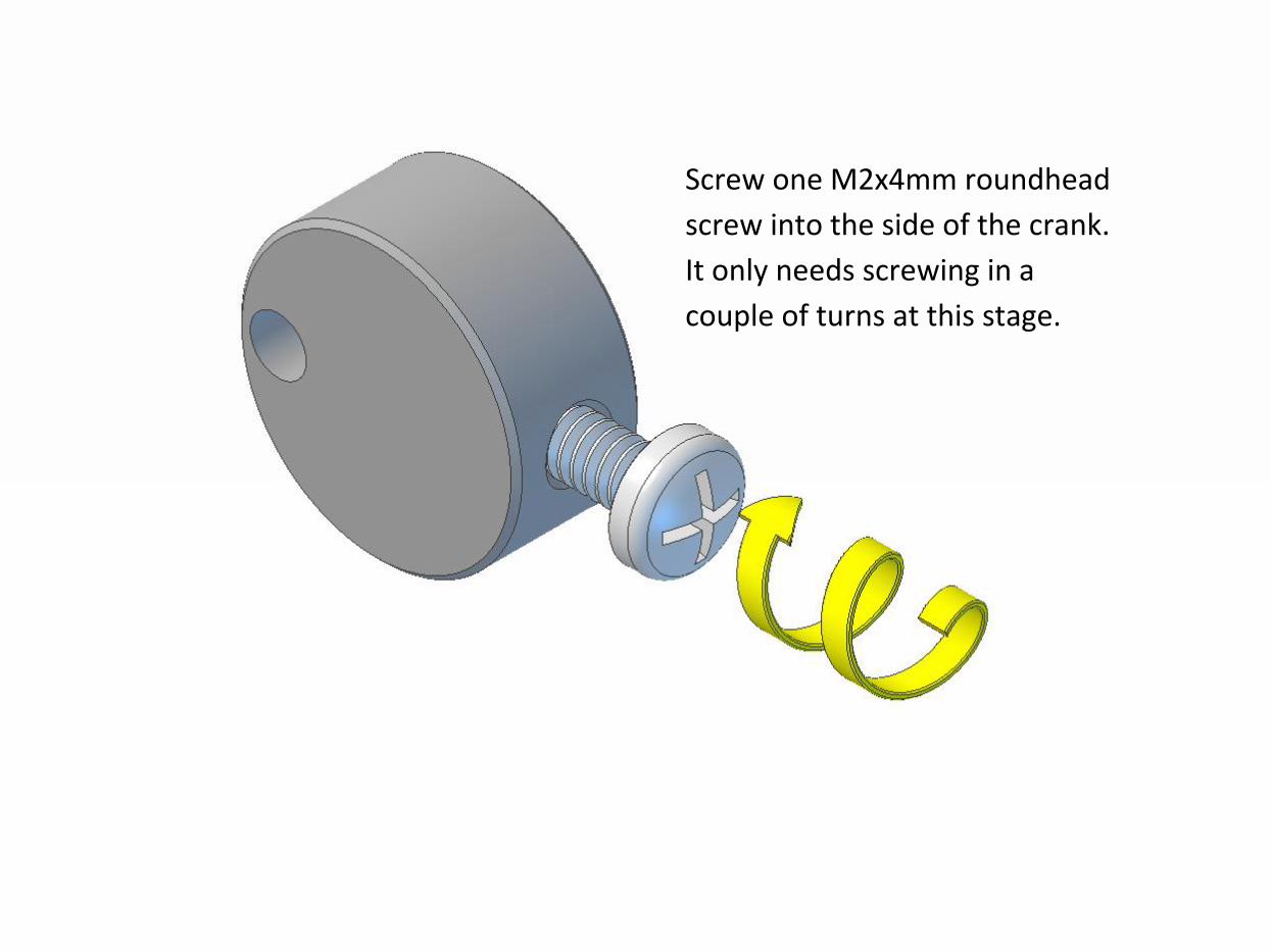
Screw one M2x4mm roundhead
screw into the side of the crank.
It only needs screwing in a
couple of turns at this stage.
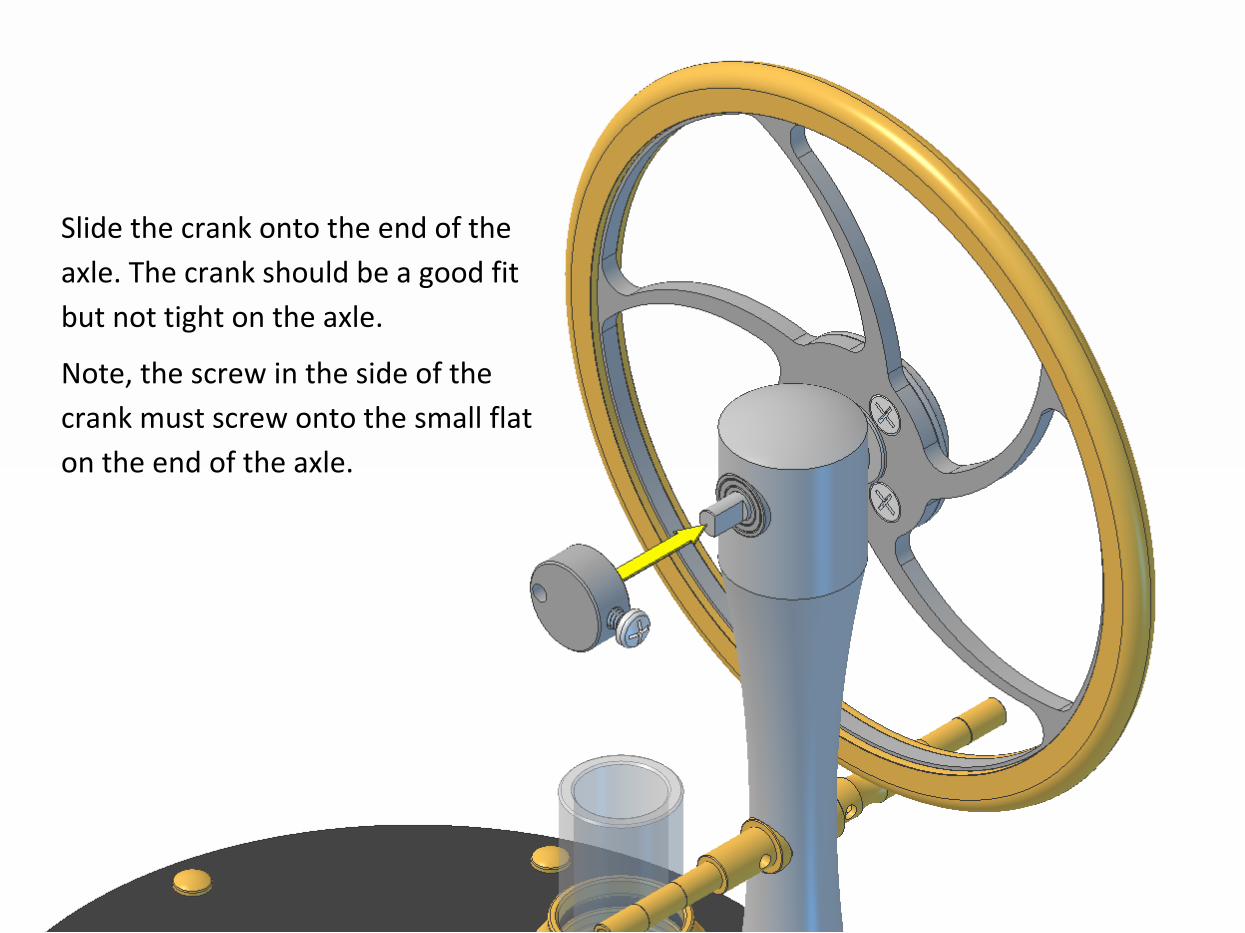
Slide the crank onto the end of the
axle. The crank should be a good fit
but not tight on the axle.
Note, the screw in the side of the
crank must screw onto the small flat
on the end of the axle.
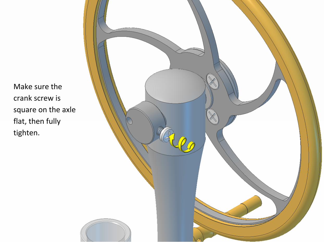
Make sure the
crank screw is
square on the axle
flat, then fully
tighten.
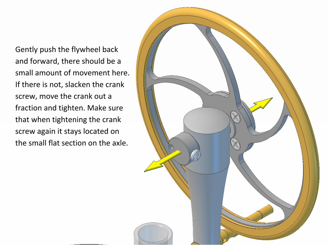
Gently push the flywheel back
and forward, there should be a
small amount of movement here.
If there is not, slacken the crank
screw, move the crank out a
fraction and tighten. Make sure
that when tightening the crank
screw again it stays located on
the small flat section on the axle.
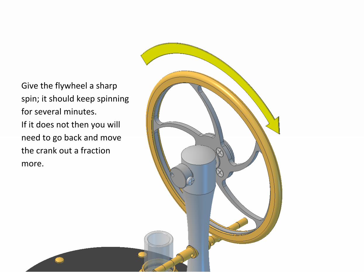
Give the flywheel a sharp
spin; it should keep spinning
for several minutes.
If it does not then you will
need to go back and move
the crank out a fraction
more.
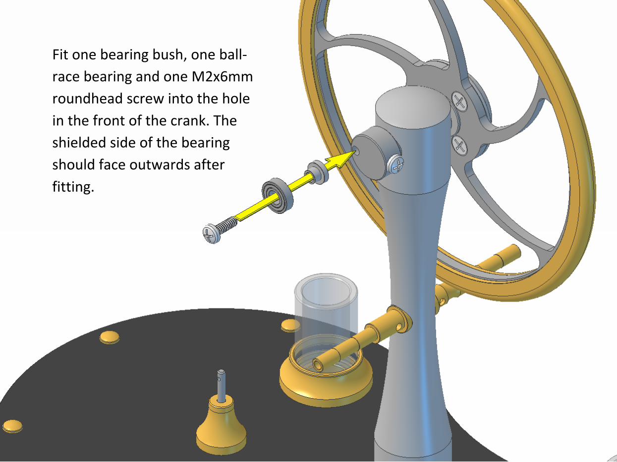
Fit one bearing bush, one ball-
race bearing and one M2x6mm
roundhead screw into the hole
in the front of the crank. The
shielded side of the bearing
should face outwards after
fitting.
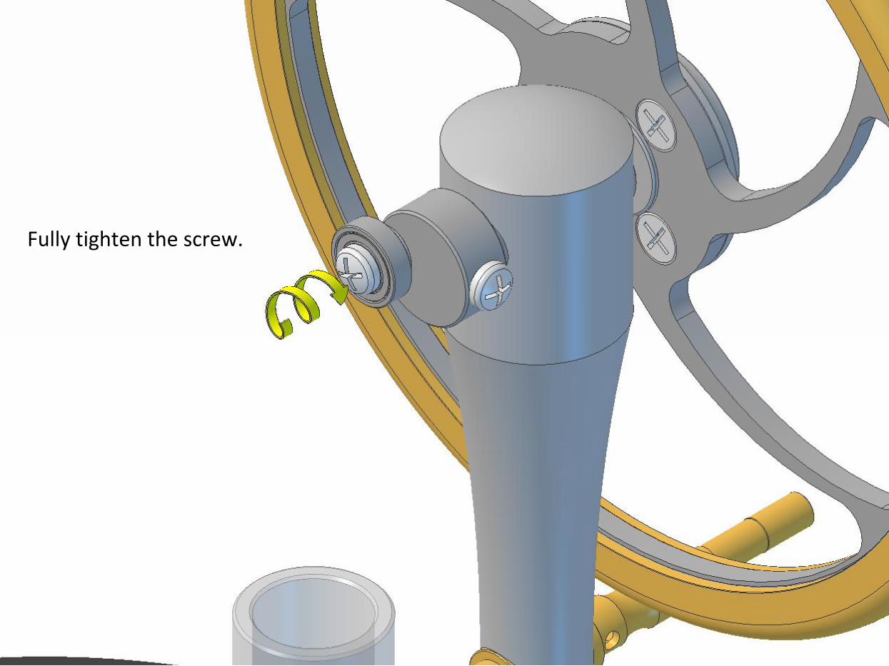
Fully tighten the screw.

Fit two ball-race bearings into the first T-
bar. The bearings have a dust shield on one
side and are open on the other. The
shielded sides should face outwards after
fitting.
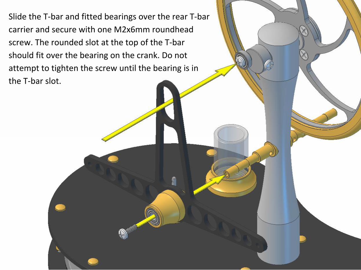
Slide the T-bar and fitted bearings over the rear T-bar
carrier and secure with one M2x6mm roundhead
screw. The rounded slot at the top of the T-bar
should fit over the bearing on the crank. Do not
attempt to tighten the screw until the bearing is in
the T-bar slot.
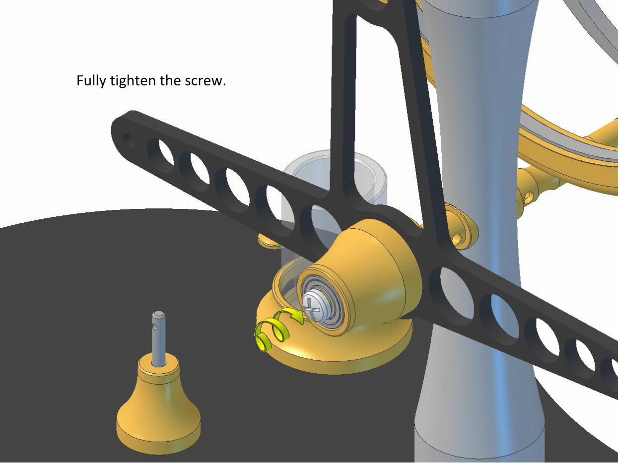
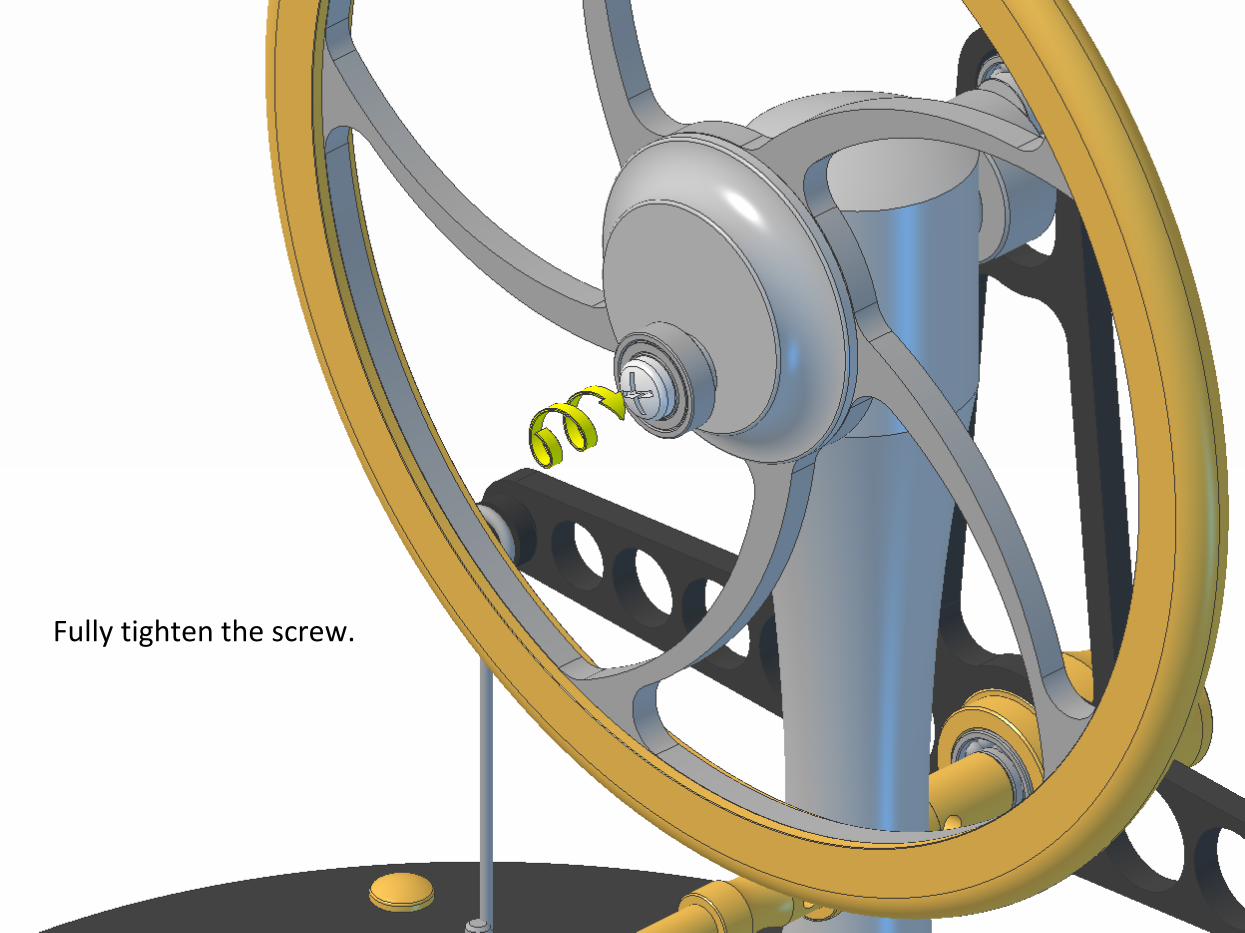
Fully tighten the screw.
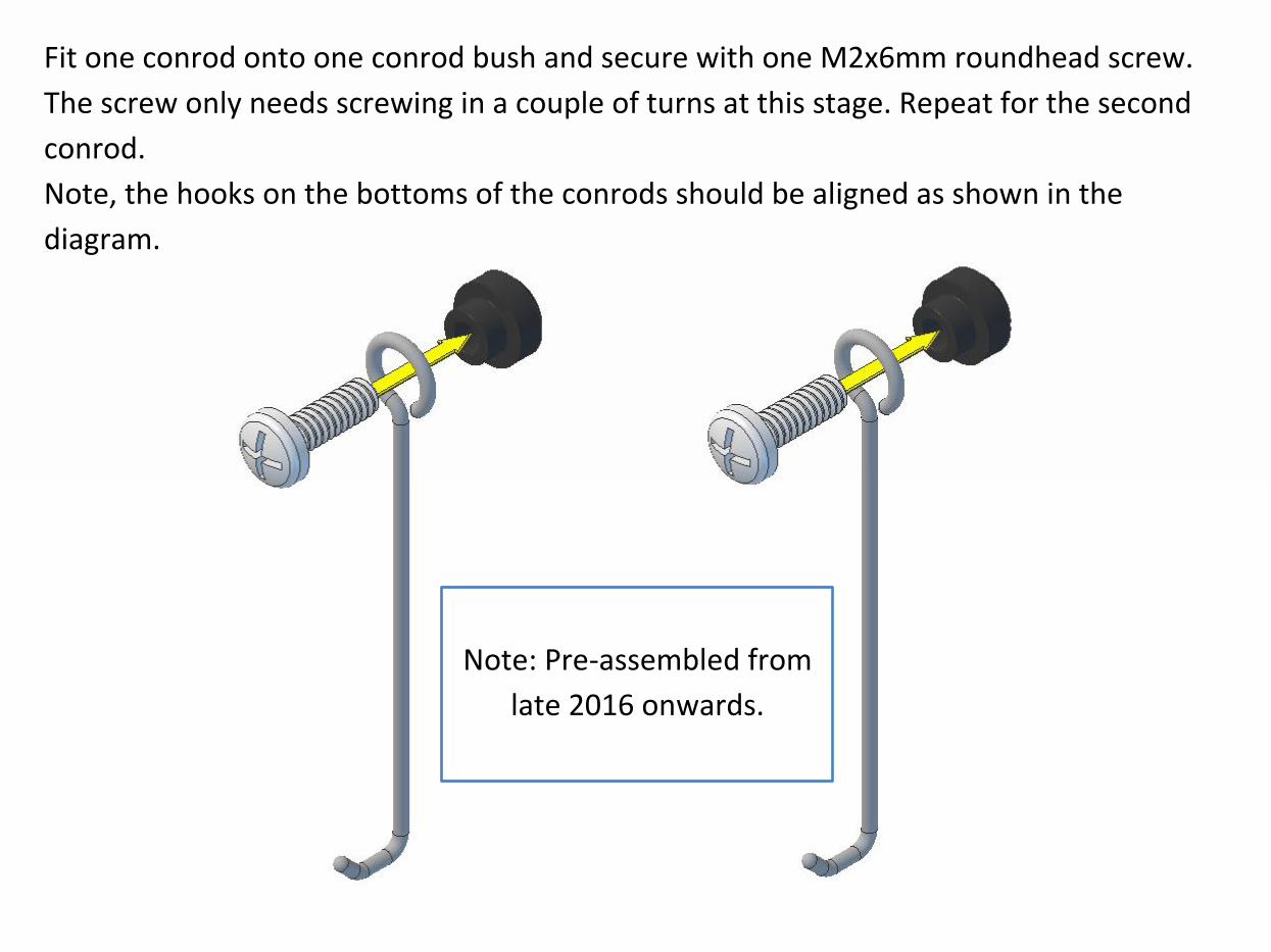
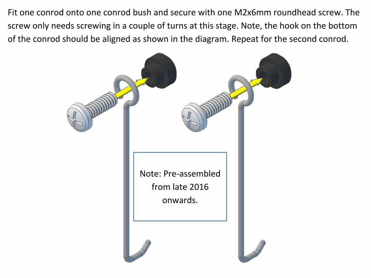
Fit one conrod onto one conrod bush and secure with one M2x6mm roundhead screw.
The screw only needs screwing in a couple of turns at this stage. Repeat for the second
conrod.
Note, the hooks on the bottoms of the conrods should be aligned as shown in the
diagram.
Note: Pre-assembled from
late 2016 onwards.
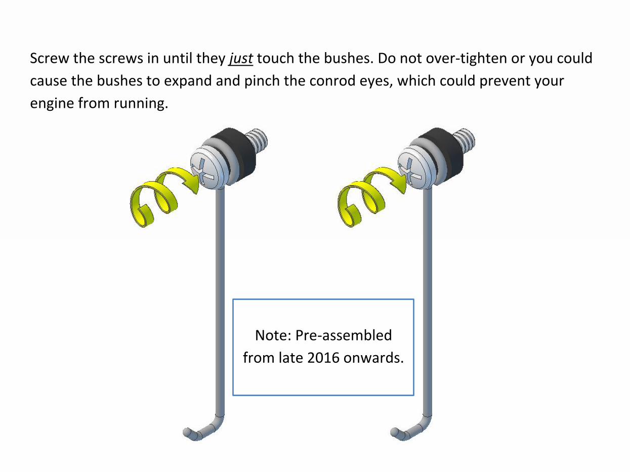
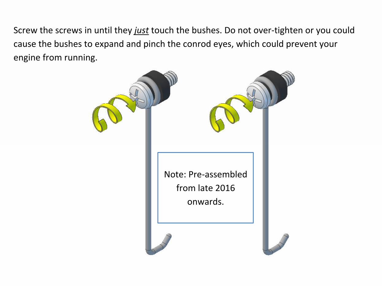
Screw the screws in until they just touch the bushes. Do not over-tighten or you could
cause the bushes to expand and pinch the conrod eyes, which could prevent your
engine from running.
Note: Pre-assembled
from late 2016 onwards.
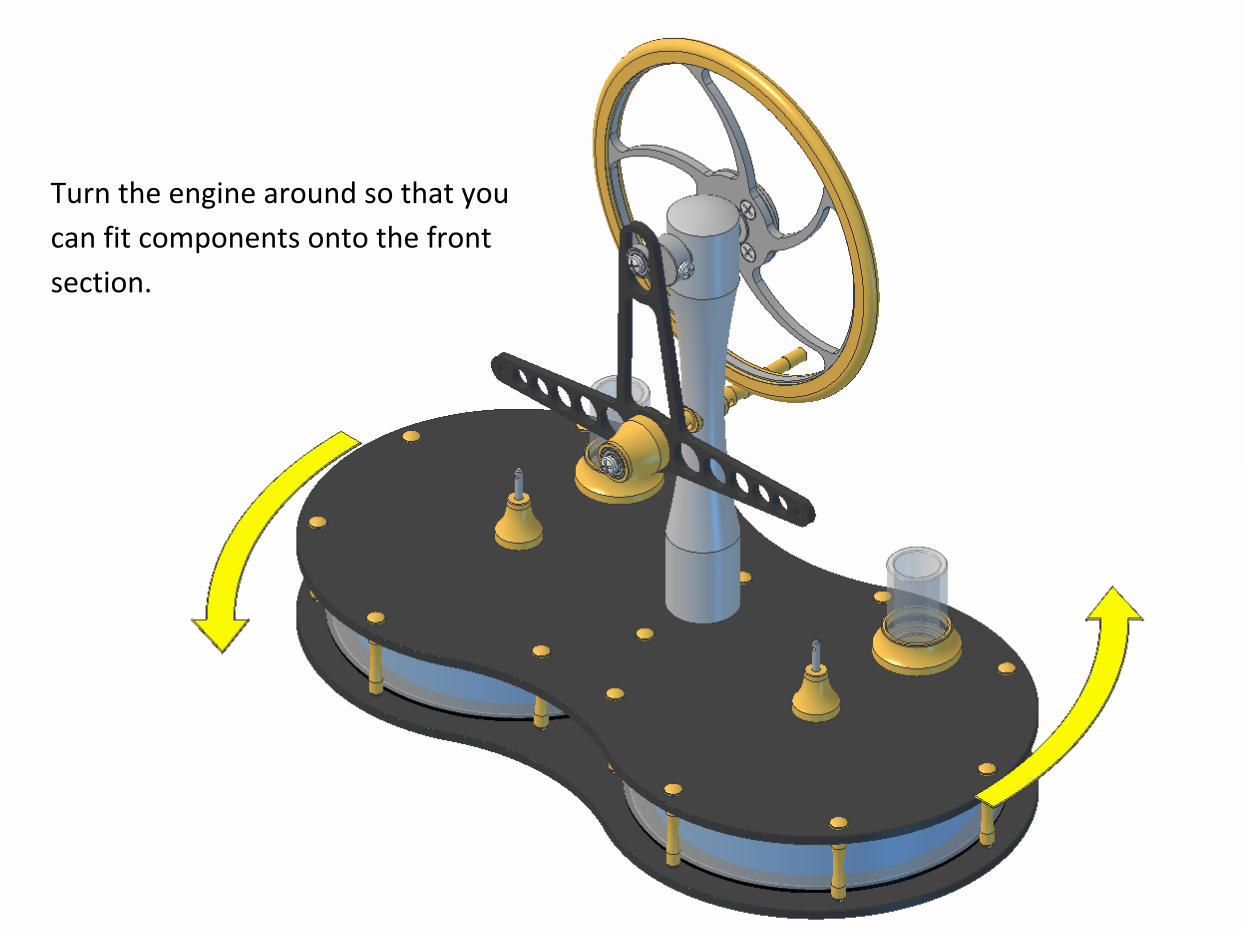
Turn the engine around so that you
can fit components onto the front
section.
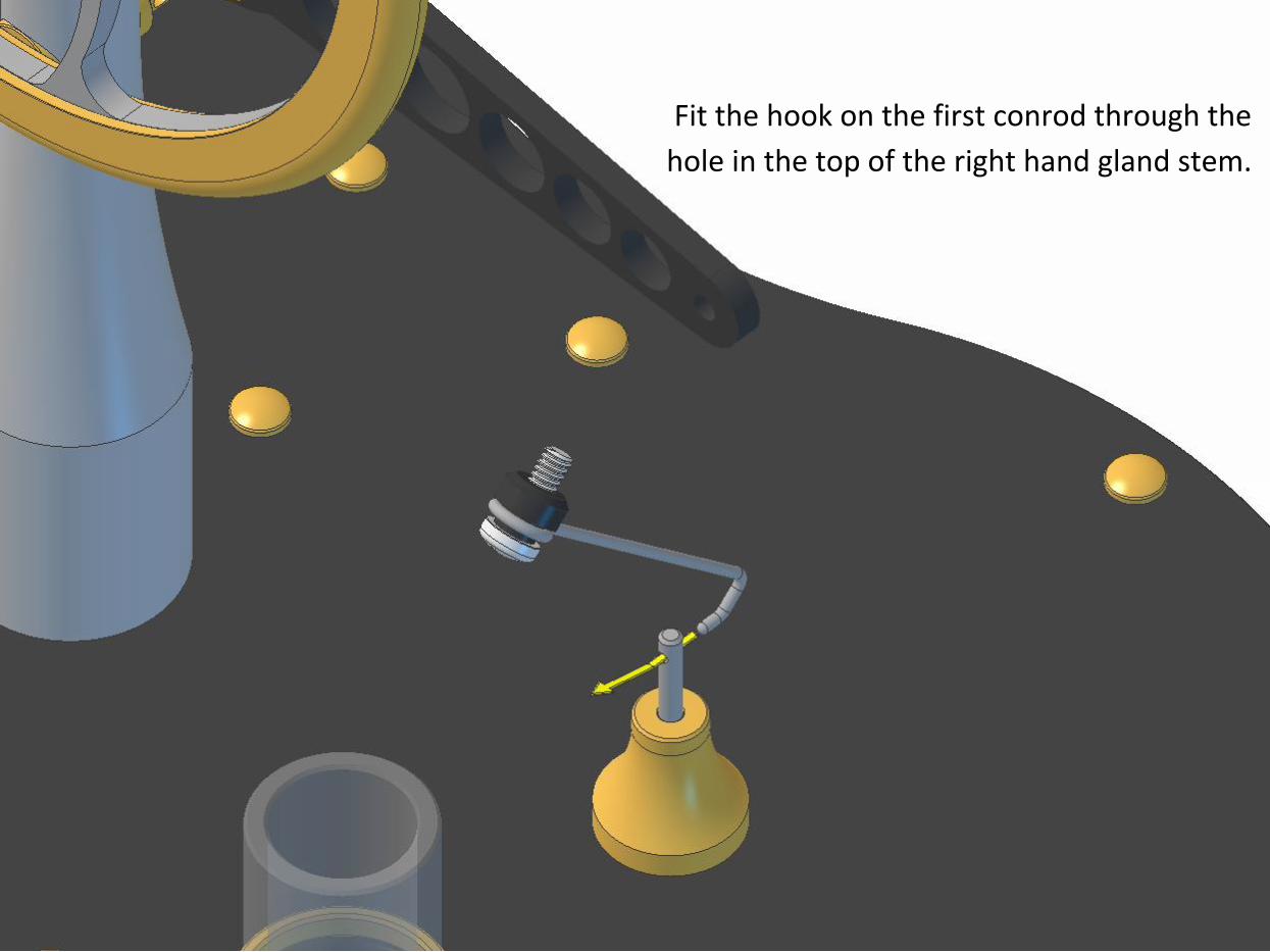
Fit the hook on the first conrod through the
hole in the top of the right hand gland stem.
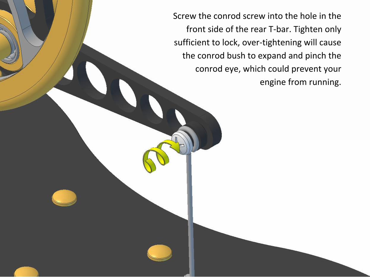
Screw the conrod screw into the hole in the
front side of the rear T-bar. Tighten only
sufficient to lock, over-tightening will cause
the conrod bush to expand and pinch the
conrod eye, which could prevent your
engine from running.
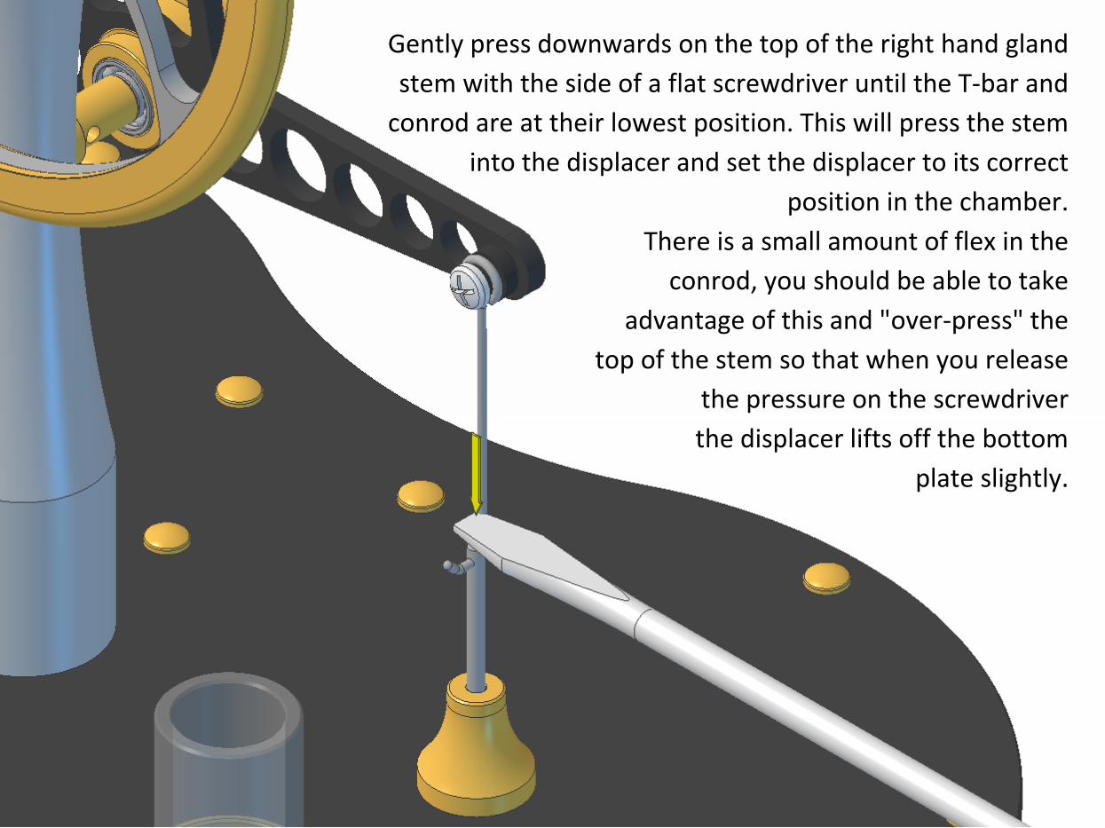
Gently press downwards on the top of the right hand gland
stem with the side of a flat screwdriver until the T-bar and
conrod are at their lowest position. This will press the stem
into the displacer and set the displacer to its correct
position in the chamber.
There is a small amount of flex in the
conrod, you should be able to take
advantage of this and "over-press" the
top of the stem so that when you release
the pressure on the screwdriver
the displacer lifts off the bottom
plate slightly.
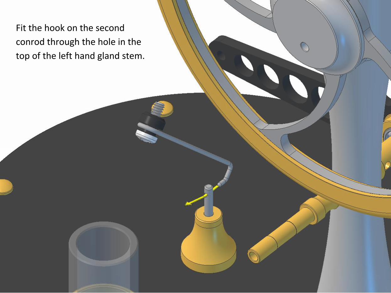
Fit the hook on the second
conrod through the hole in the
top of the left hand gland stem.
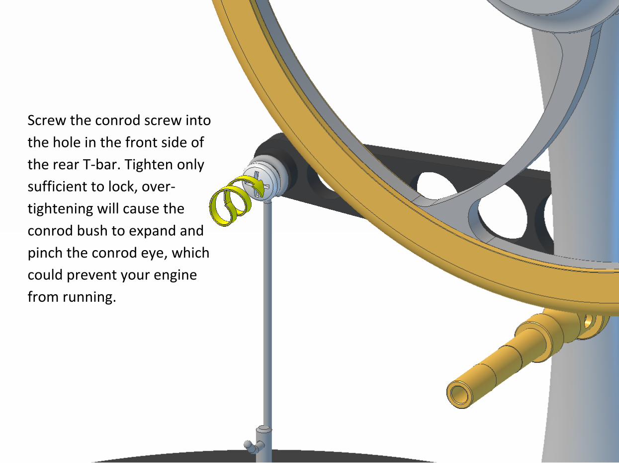
Screw the conrod screw into
the hole in the front side of
the rear T-bar. Tighten only
sufficient to lock, over-
tightening will cause the
conrod bush to expand and
pinch the conrod eye, which
could prevent your engine
from running.
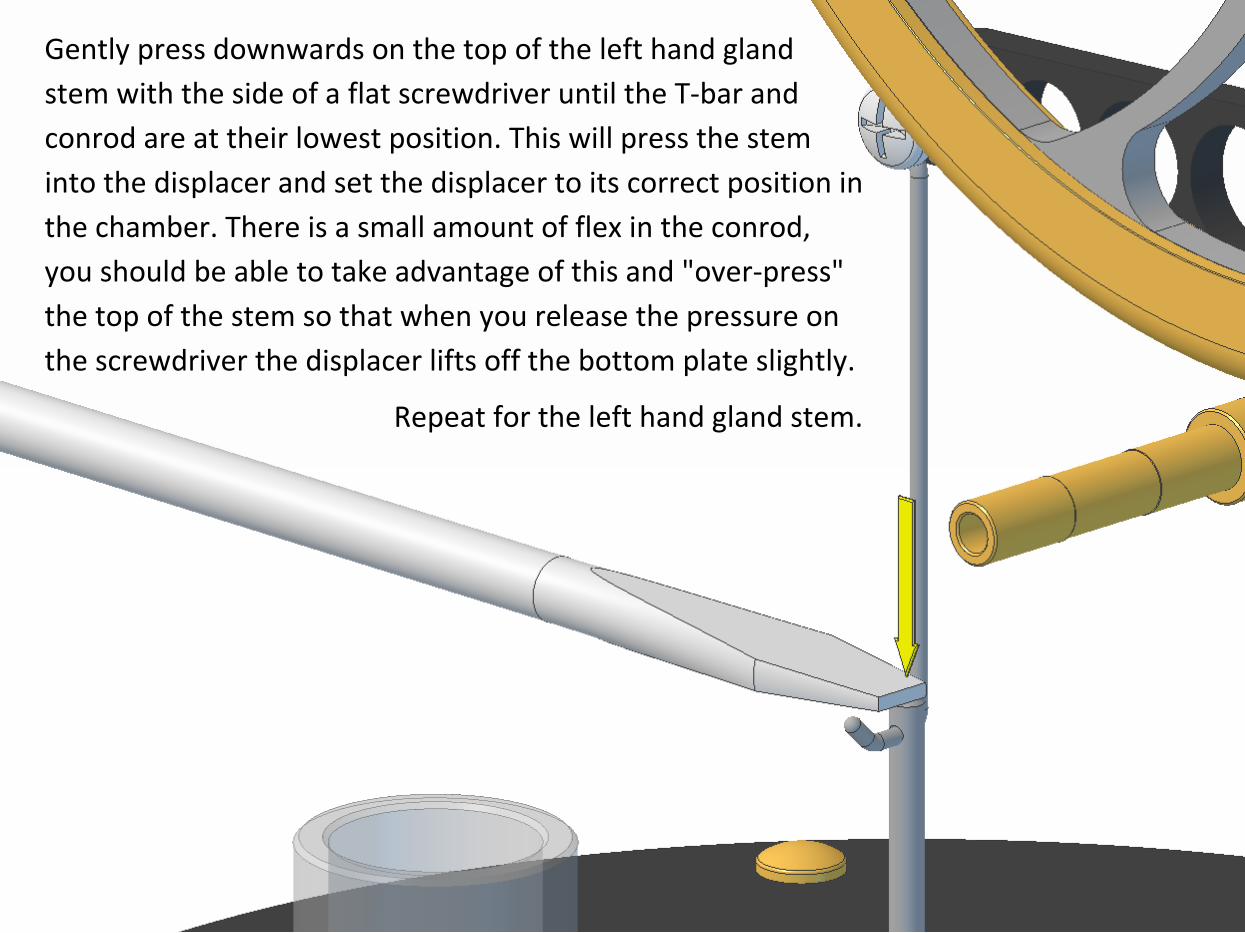
Gently press downwards on the top of the left hand gland
stem with the side of a flat screwdriver until the T-bar and
conrod are at their lowest position. This will press the stem
into the displacer and set the displacer to its correct position in
the chamber. There is a small amount of flex in the conrod,
you should be able to take advantage of this and "over-press"
the top of the stem so that when you release the pressure on
the screwdriver the displacer lifts off the bottom plate slightly.
Repeat for the left hand gland stem.
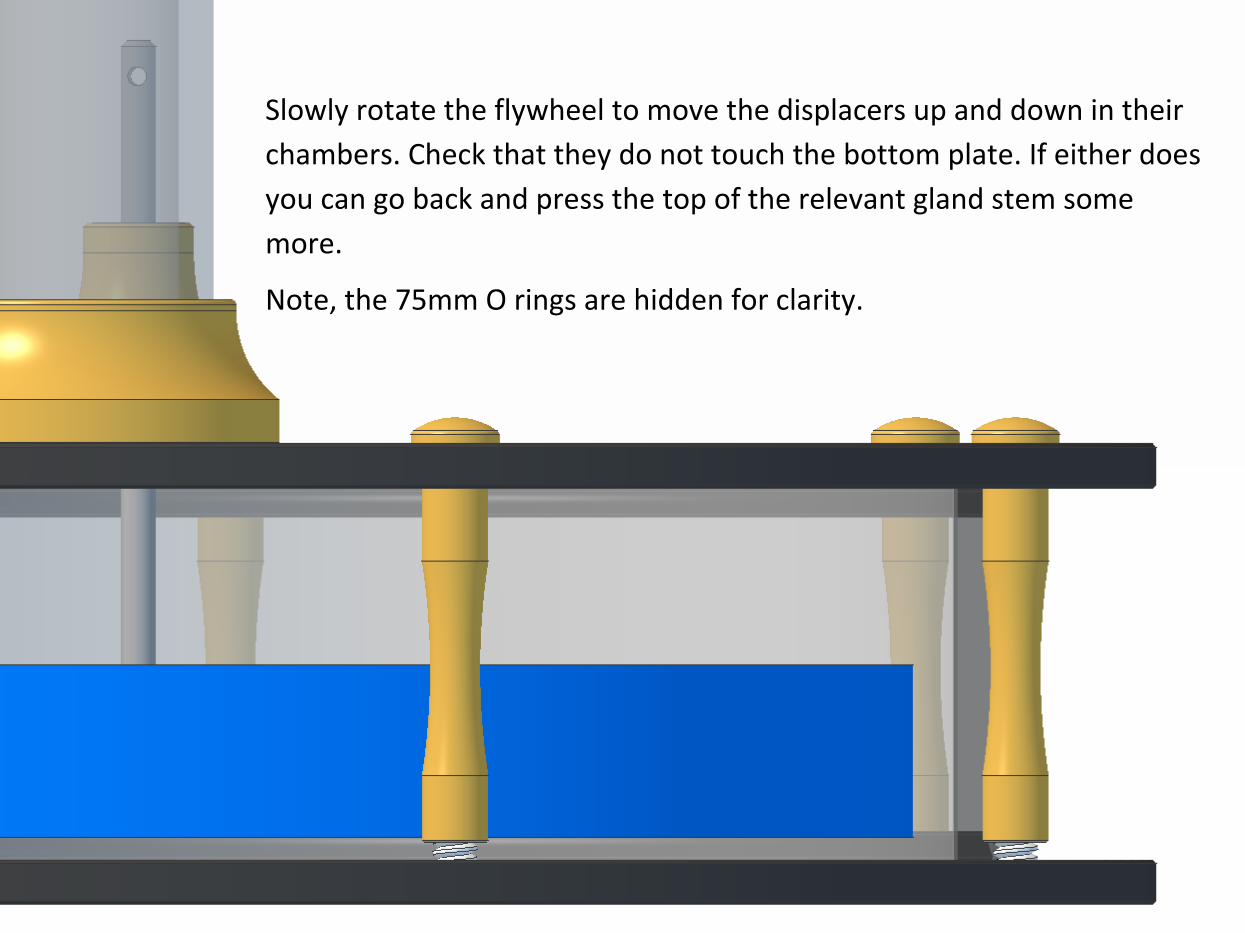
Slowly rotate the flywheel to move the displacers up and down in their
chambers. Check that they do not touch the bottom plate. If either does
you can go back and press the top of the relevant gland stem some
more.
Note, the 75mm O rings are hidden for clarity.
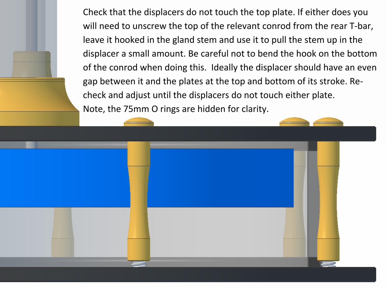
Check that the displacers do not touch the top plate. If either does you
will need to unscrew the top of the relevant conrod from the rear T-bar,
leave it hooked in the gland stem and use it to pull the stem up in the
displacer a small amount. Be careful not to bend the hook on the bottom
of the conrod when doing this. Ideally the displacer should have an even
gap between it and the plates at the top and bottom of its stroke. Re-
check and adjust until the displacers do not touch either plate.
Note, the 75mm O rings are hidden for clarity.
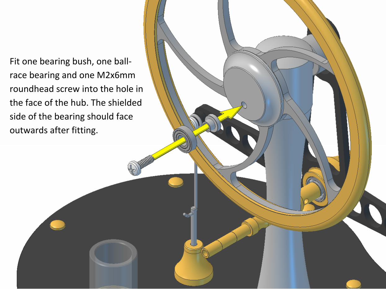
Fit one bearing bush, one ball-
race bearing and one M2x6mm
roundhead screw into the hole in
the face of the hub. The shielded
side of the bearing should face
outwards after fitting.
Fully tighten the screw.
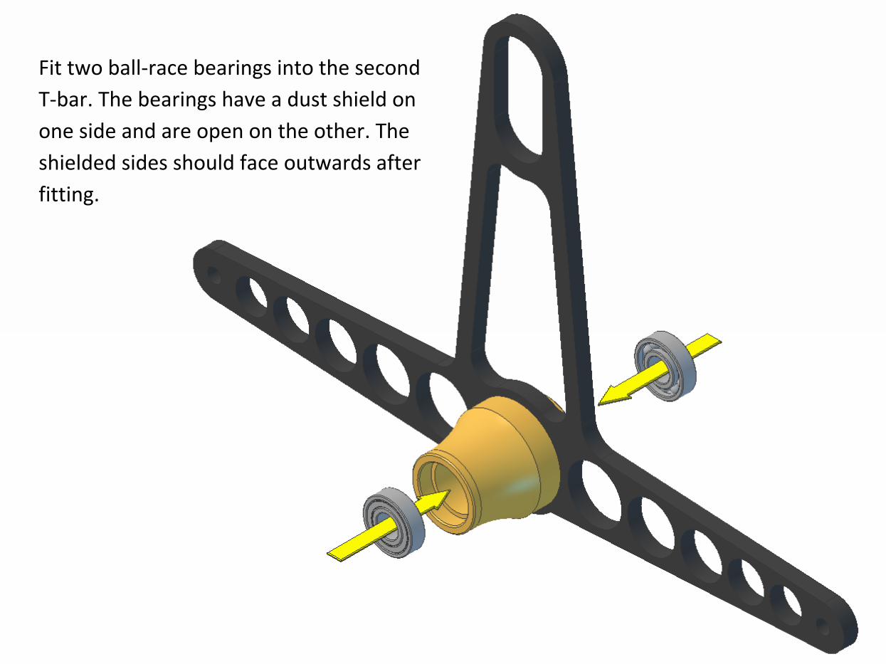
Fit two ball-race bearings into the second
T-bar. The bearings have a dust shield on
one side and are open on the other. The
shielded sides should face outwards after
fitting.
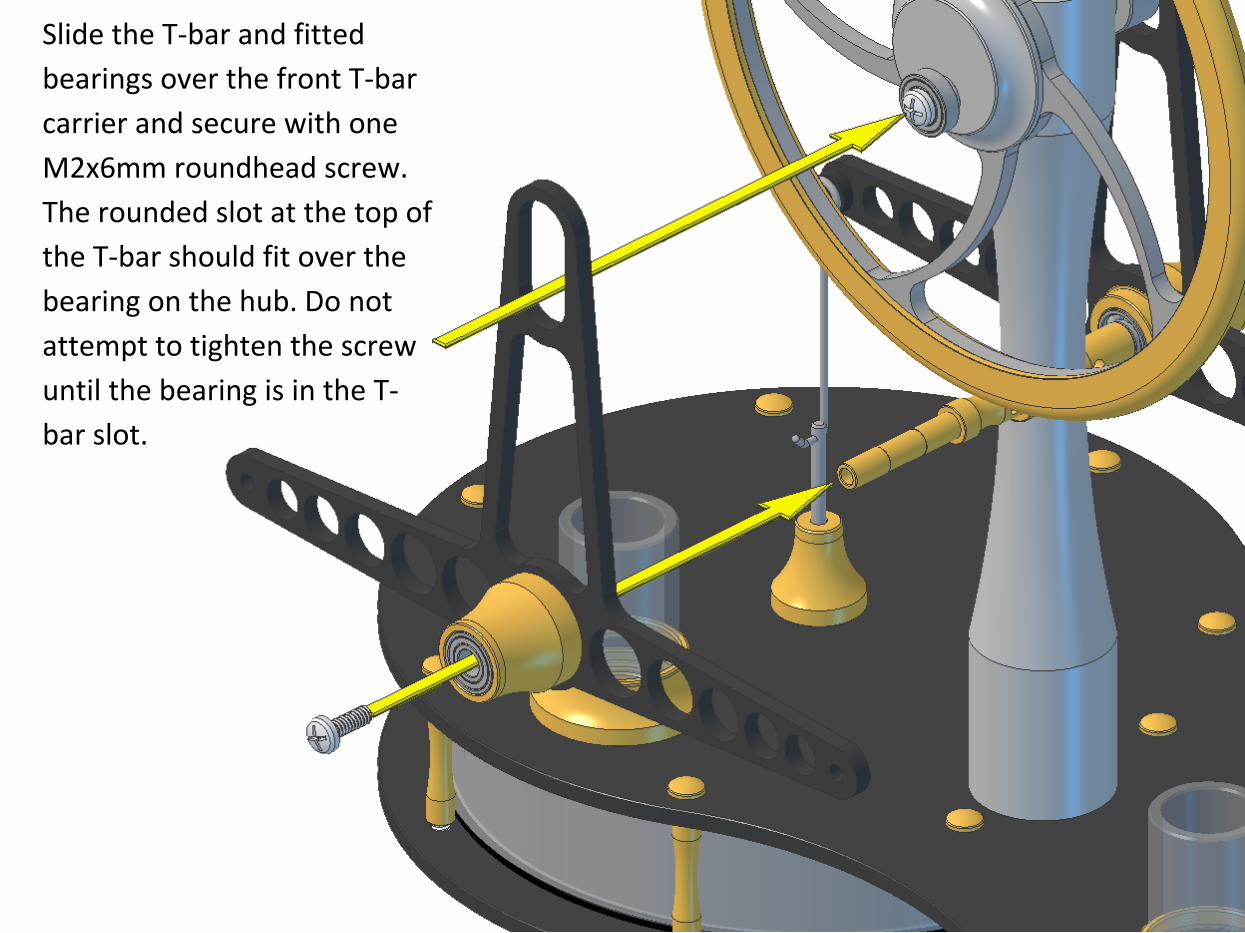
Slide the T-bar and fitted
bearings over the front T-bar
carrier and secure with one
M2x6mm roundhead screw.
The rounded slot at the top of
the T-bar should fit over the
bearing on the hub. Do not
attempt to tighten the screw
until the bearing is in the T-
bar slot.
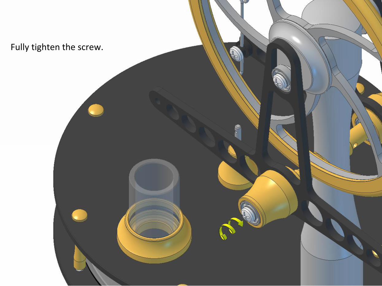
Fully tighten the screw.
Fit one conrod onto one conrod bush and secure with one M2x6mm roundhead screw. The
screw only needs screwing in a couple of turns at this stage. Note, the hook on the bottom
of the conrod should be aligned as shown in the diagram. Repeat for the second conrod.
Note: Pre-assembled
from late 2016
onwards.
Screw the screws in until they just touch the bushes. Do not over-tighten or you could
cause the bushes to expand and pinch the conrod eyes, which could prevent your
engine from running.
Note: Pre-assembled
from late 2016
onwards.
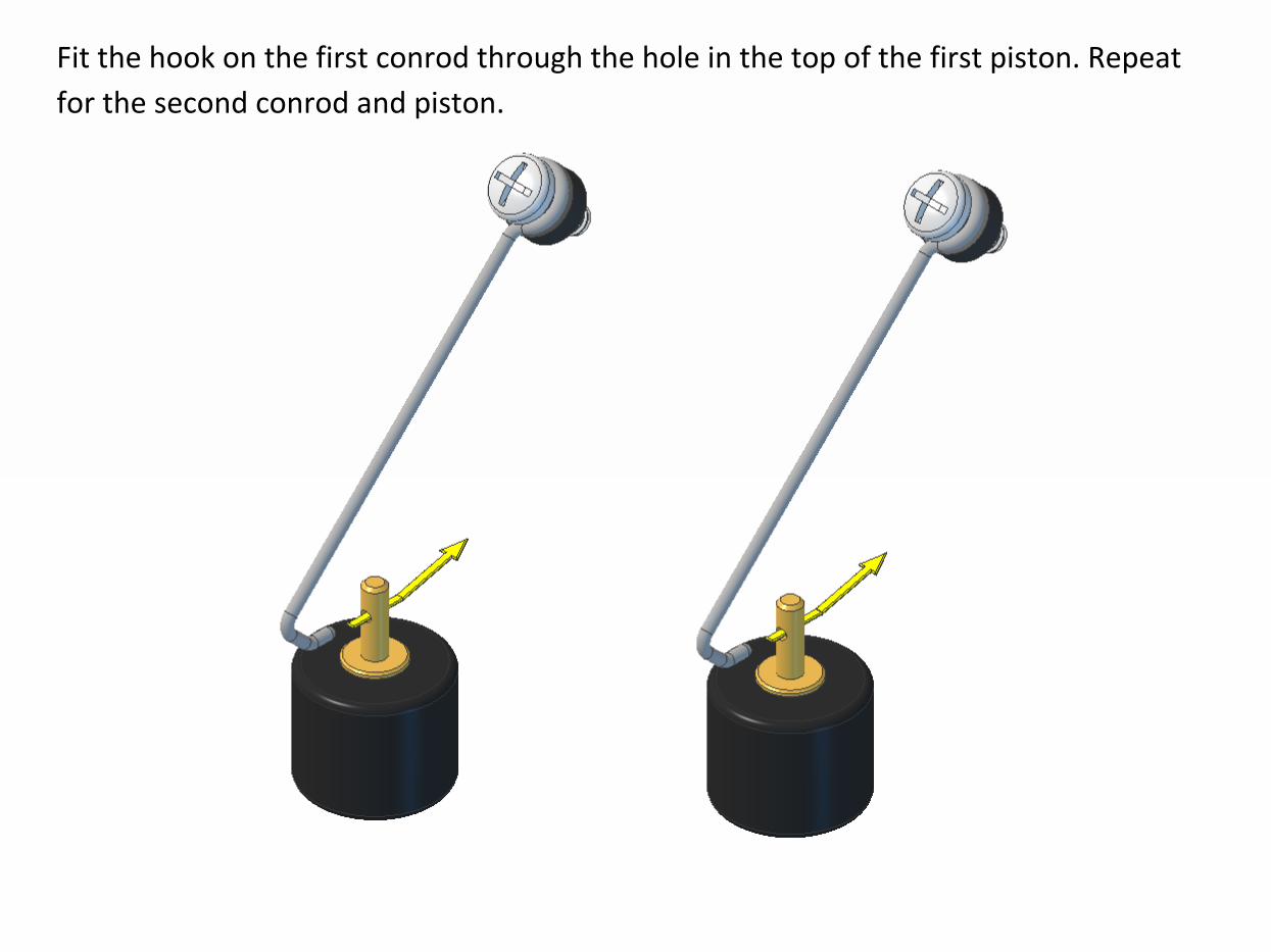
Fit the hook on the first conrod through the hole in the top of the first piston. Repeat
for the second conrod and piston.
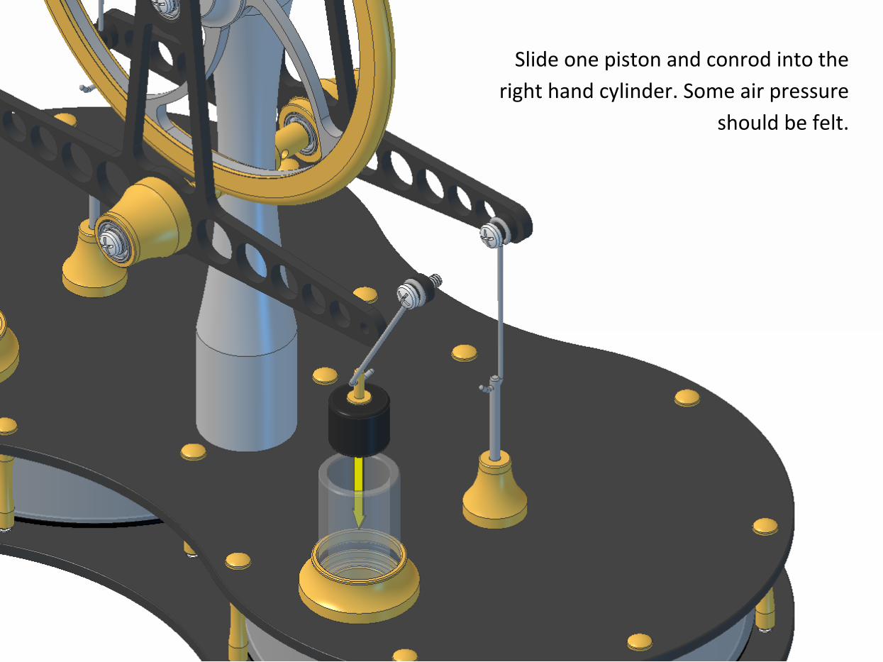
Slide one piston and conrod into the
right hand cylinder. Some air pressure
should be felt.
Screw the conrod screw into the
threaded hole in the front side of
the front T-bar. Tighten only
sufficient to lock, over-
tightening will cause the
conrod bush to expand and pinch
the conrod eye, which could
prevent your engine from
running.
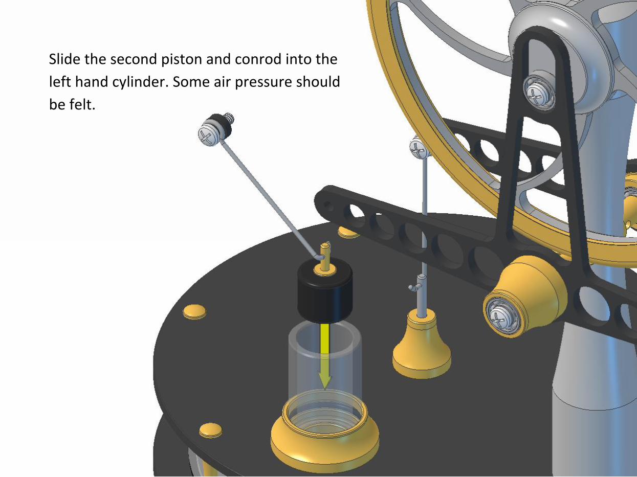
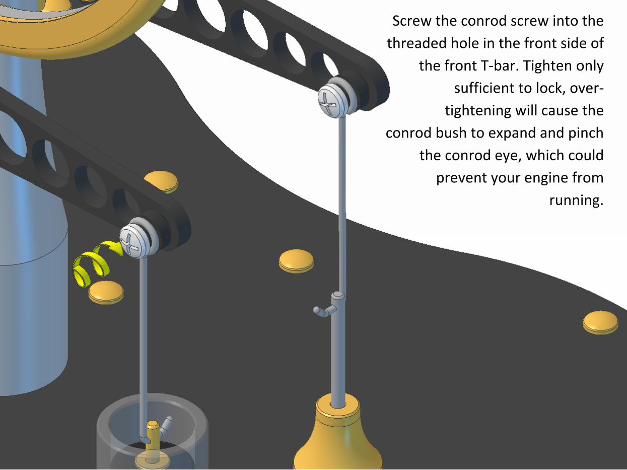
Slide the second piston and conrod into the
left hand cylinder. Some air pressure should
be felt.
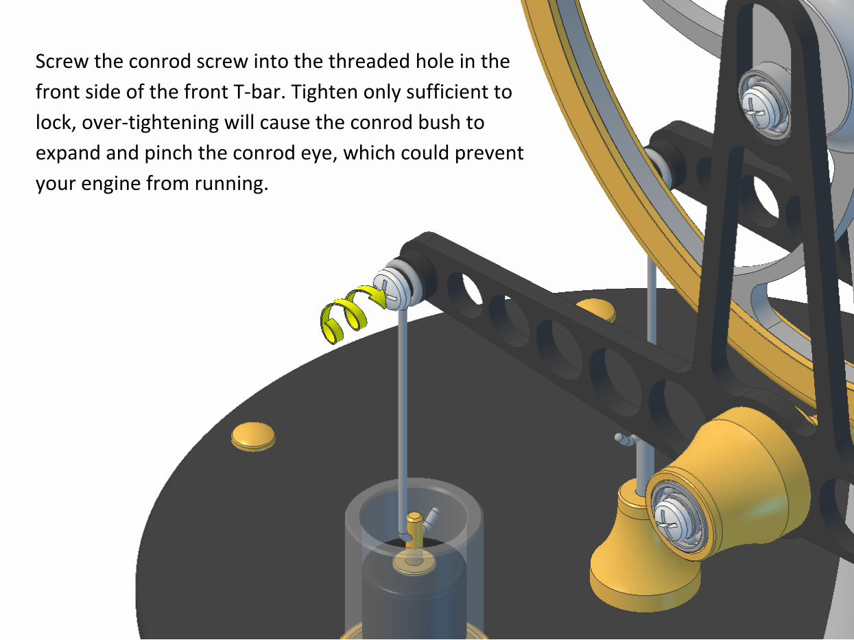
Screw the conrod screw into the threaded hole in the
front side of the front T-bar. Tighten only sufficient to
lock, over-tightening will cause the conrod bush to
expand and pinch the conrod eye, which could prevent
your engine from running.
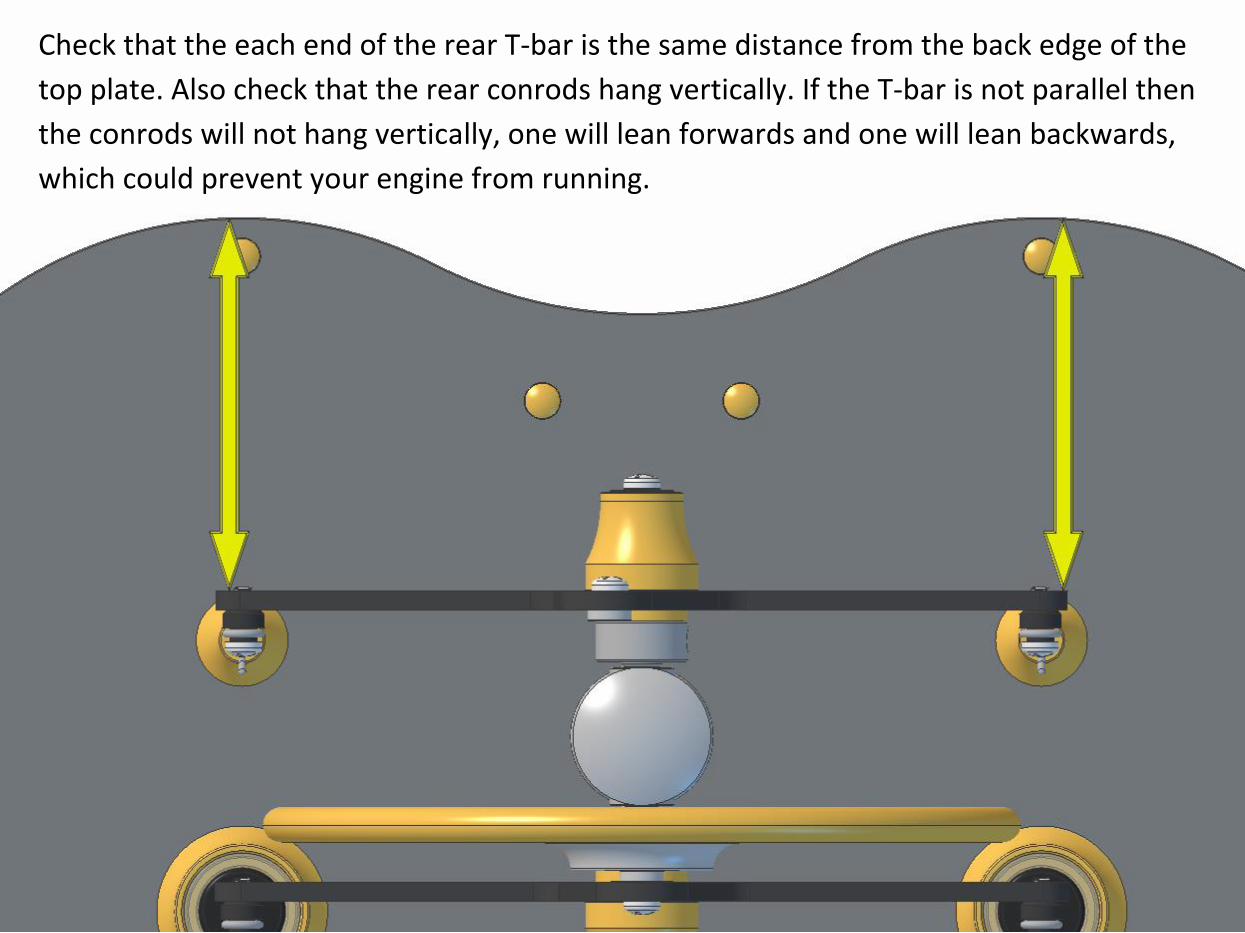
Check that the each end of the rear T-bar is the same distance from the back edge of the
top plate. Also check that the rear conrods hang vertically. If the T-bar is not parallel then
the conrods will not hang vertically, one will lean forwards and one will lean backwards,
which could prevent your engine from running.
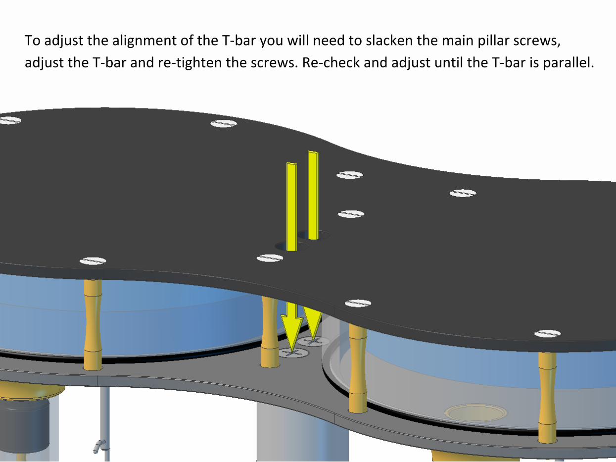
To adjust the alignment of the T-bar you will need to slacken the main pillar screws,
adjust the T-bar and re-tighten the screws. Re-check and adjust until the T-bar is parallel.
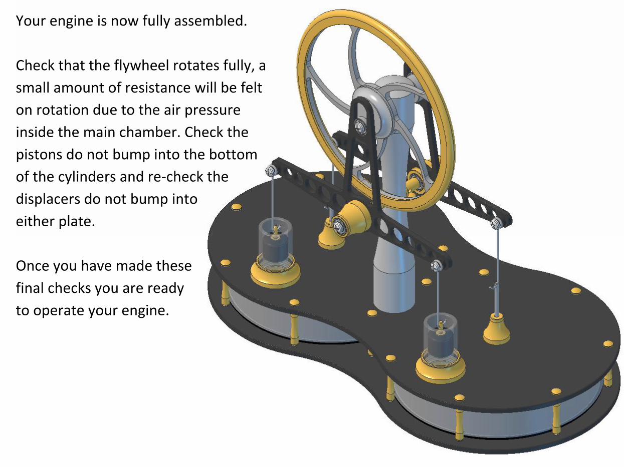
Your engine is now fully assembled.
Check that the flywheel rotates fully, a
small amount of resistance will be felt
on rotation due to the air pressure
inside the main chamber. Check the
pistons do not bump into the bottom
of the cylinders and re-check the
displacers do not bump into
either plate.
Once you have made these
final checks you are ready
to operate your engine.
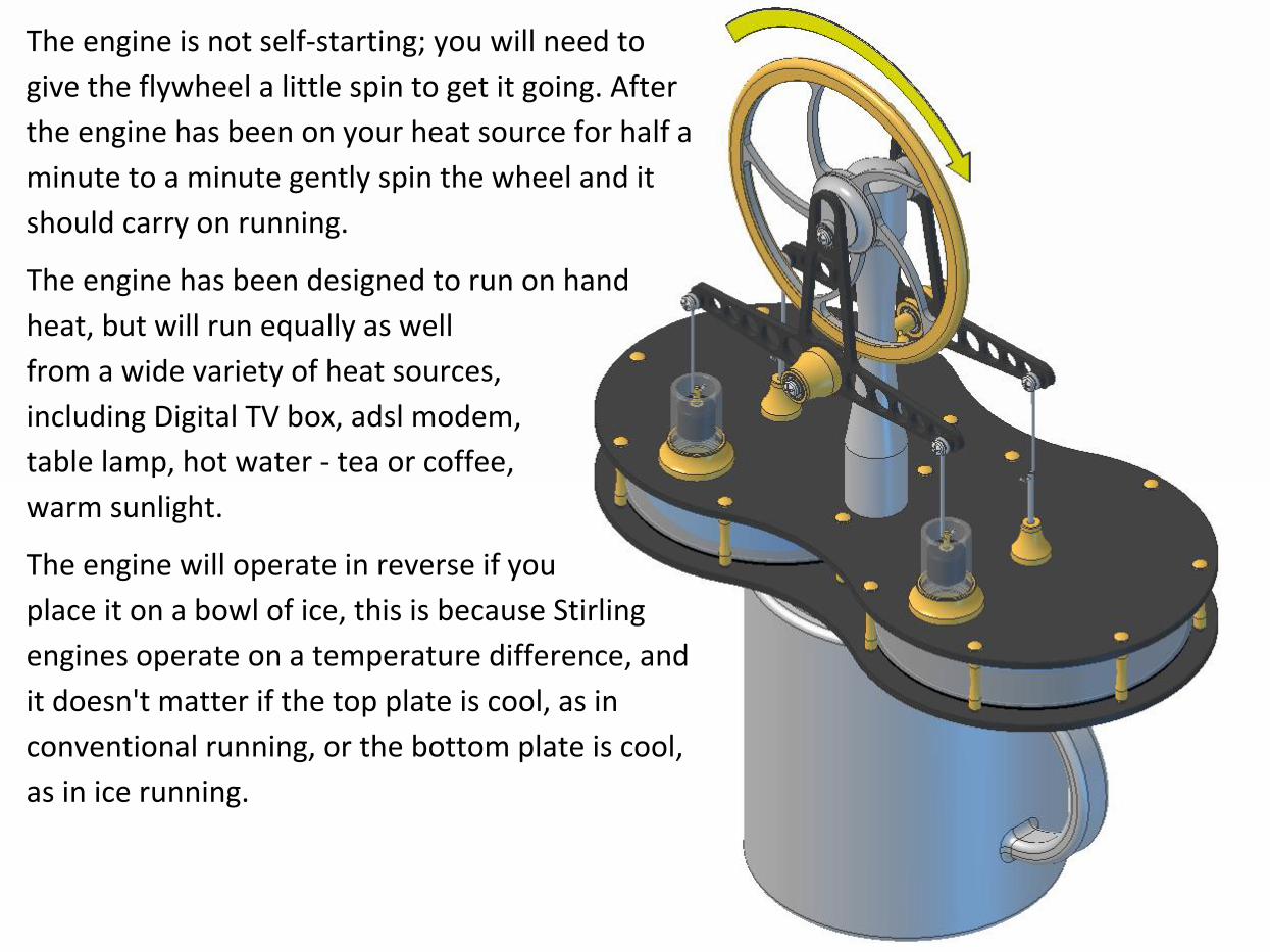
The engine is not self-starting; you will need to
give the flywheel a little spin to get it going. After
the engine has been on your heat source for half a
minute to a minute gently spin the wheel and it
should carry on running.
The engine has been designed to run on hand
heat, but will run equally as well
from a wide variety of heat sources,
including Digital TV box, adsl modem,
table lamp, hot water - tea or coffee,
warm sunlight.
The engine will operate in reverse if you
place it on a bowl of ice, this is because Stirling
engines operate on a temperature difference, and
it doesn't matter if the top plate is cool, as in
conventional running, or the bottom plate is cool,
as in ice running.
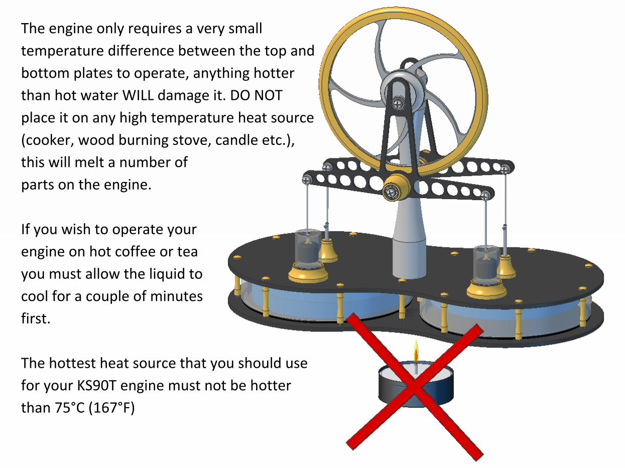
The engine only requires a very small
temperature difference between the top and
bottom plates to operate, anything hotter
than hot water WILL damage it. DO NOT
place it on any high temperature heat source
(cooker, wood burning stove, candle etc.),
this will melt a number of
parts on the engine.
If you wish to operate your
engine on hot coffee or tea
you must allow the liquid to
cool for a couple of minutes
first.
The hottest heat source that you should use
for your KS90T engine must not be hotter
than 75°C (167°F)
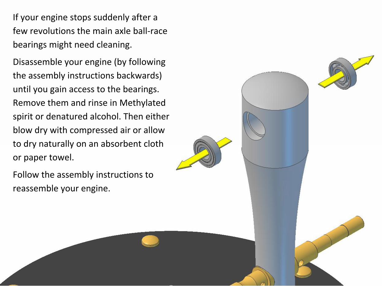
If your engine stops suddenly after a
few revolutions the main axle ball-race
bearings might need cleaning.
Disassemble your engine (by following
the assembly instructions backwards)
until you gain access to the bearings.
Remove them and rinse in Methylated
spirit or denatured alcohol. Then either
blow dry with compressed air or allow
to dry naturally on an absorbent cloth
or paper towel.
Follow the assembly instructions to
reassemble your engine.
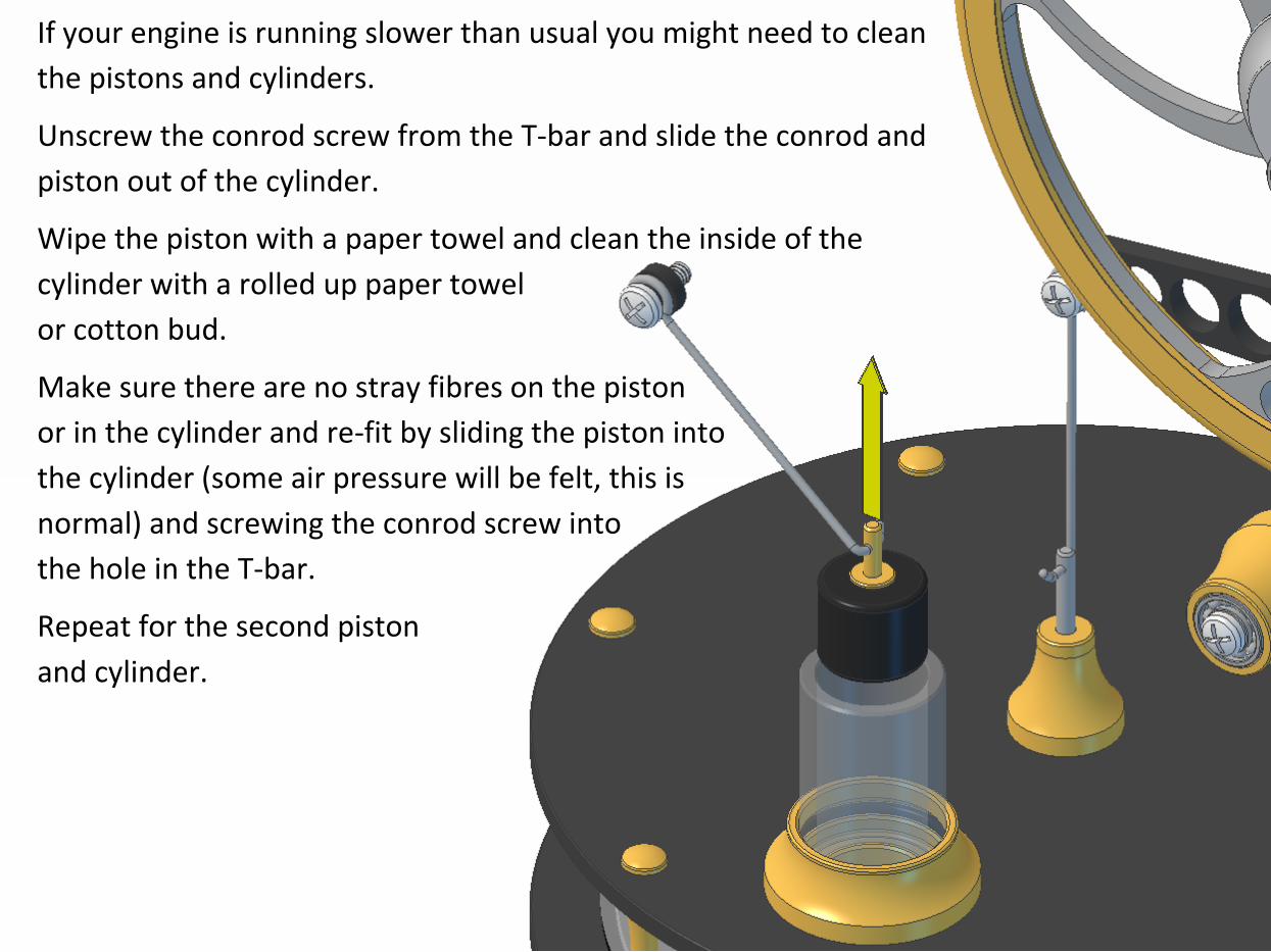
If your engine is running slower than usual you might need to clean
the pistons and cylinders.
Unscrew the conrod screw from the T-bar and slide the conrod and
piston out of the cylinder.
Wipe the piston with a paper towel and clean the inside of the
cylinder with a rolled up paper towel
or cotton bud.
Make sure there are no stray fibres on the piston
or in the cylinder and re-fit by sliding the piston into
the cylinder (some air pressure will be felt, this is
normal) and screwing the conrod screw into
the hole in the T-bar.
Repeat for the second piston
and cylinder.
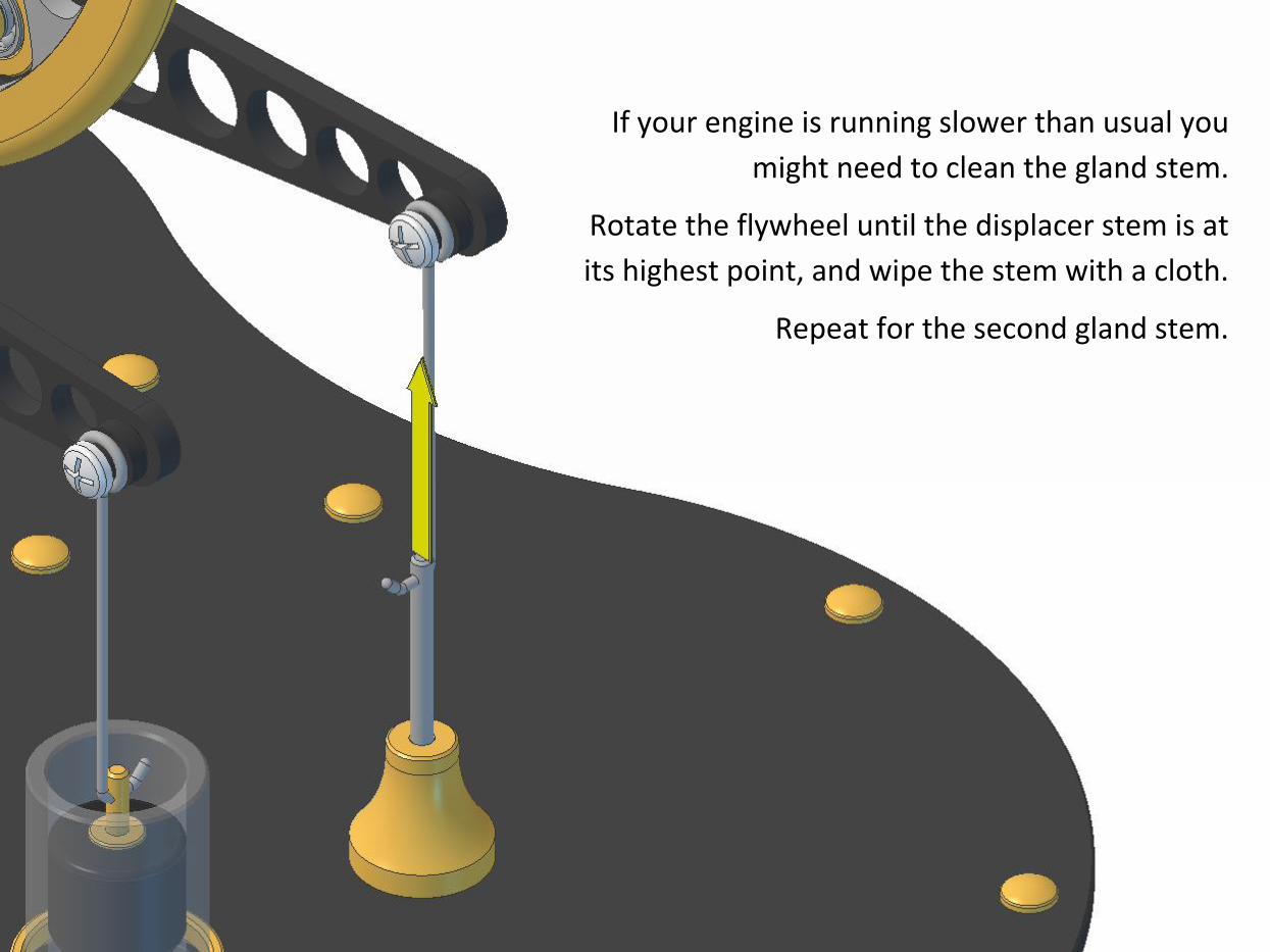
If your engine is running slower than usual you
might need to clean the gland stem.
Rotate the flywheel until the displacer stem is at
its highest point, and wipe the stem with a cloth.
Repeat for the second gland stem.