Embed Size (px)
Citation preview

SER-Kits O/O1 Loco Instructions © Text and pictures Dan Garrett 1.5.2010 Page 1 of 48
SER-Kits
SER/SECR/SR/EKR Stirling/Wainwright Class O/O1 goods locomotive Instructions for assembly – revised March 2014
Table of contents
O/O1 Etched parts numbering 2 Section 1: Introduction, kit specification, Scale 7, tools needed 4 Section 2: Decisions to make: loco version, motor & gearbox, wheels- 6 Section 3: Constructing the Locomotive Chassis 8 Section 4: Fitting the Dummy Motion 13 Section 5: Making the coupling rods 16 Section 6: Getting the chassis running 17 Section 7: Further Detailing on the Chassis (brakes, sandboxes, reverser etc) 18 Section 8: Constructing the locomotive body - 1 22 Section 9: Preparing the Resin Boiler 23 Section 10: Assembling the Loco body – 2 (splashers, cab, etc) 24 Section 11: Adding etched detail to the Loco body 26 Section 11: Detailing the Loco (castings) 27 Section 12: cab fittings- 29 Section 13: Constructing the tender – etched parts 31 Section 14: Springing loco & tender, adjusting running, fitting tender brakes 34 Section 15: Tender fittings 37 Appendix A: Wooden Sandwich Buffer Beams 38 Appendix B: Troubleshooting Wheel Binding 38 Appendix C: Techniques 39 Appendix D – Boiler side reverser for many O1s 40 Appendix E: O1 Tenders 40 Kit contents 42 Historical notes 44

SER-Kits O/O1 Loco Instructions © Text and pictures Dan Garrett 1.5.2010 Page 2 of 48
O/O1 Etch numbering Numbers may be suffixed E for ‘Early’ (1878 batch) L for ‘Later’ (all other subsequent batches) or HB for “High Boiler’ or Wainwright. Also O1 for specific parts, and S7 for Scale 7.
1. Chassis, two versions, E and L. Note that “Rsp” = Rear Spacer 2. Axlebox guides 3. Firebox sides 4. Loco guard irons 5. Loco vac. brake trunnions 6. Brake hangers, links etc. (Most together within ‘chassis’; two etched separately) 7. Loco vac cylinder 8. Footplate 9. Valances 10. Front buffer beam 11. Rear buffer beam 12. Loco-tender coupling 13. Smokebox wing-plate (One contains spectacle rims R, the other, washer plates and ‘special’
board.) 14. Front wheel covers + sandboxes; 14M – extra ½ etched strips; 14SP – spare tops 15. Middle wheel covers 16. Rear wheel covers- 17. Front draw-hook washer plate 18. Cab front (spectacle plate); R – rims for spectacle glasses 19. Cab sides 20. Cab top jointing plate or whole roof for O1. 20-O1 – O1 rear roof beading. 20B-01 roof hatch. 21. Cab beading 22. Rear wheel covers (cab seats for O1) 23. Steam reverser stand and ends. 24. Cylinder cover plate (ogee plate) 25. Front sanding cranks 26. Sanding link 27. Step hangers 28. Loco steps: either E or L, or no letter suffix for O1. 29. Vertical reversing lever (early O) 30. Forked link 31. Short link (early O) 32. Reversing lever horizontal link (early O) 33. Weigh shaft crank 34. Diagonal reversing lever (later O) 35. ‘Wooden’ floor 36. Brackets for water supply cocks 37. Lamp-irons 38. Handwheels 39. Boiler band (to go against cab) 40. x 41. Tiny cranks (on vac brake spindles, loco and tender) 42. Tender sub-frame 43. Axlebox guides for Slaters bearings 44. Vac cylinder support 45. Guard irons 46. Tender frames (number on rear) 47. Axlebox guide tags 48. Footplate 49. Front tender buffer beam 50. Rear tender buffer beam

SER-Kits O/O1 Loco Instructions © Text and pictures Dan Garrett 1.5.2010 Page 3 of 48
51. Tender drawhook washer plate 52. Beading 53. Tender steps 54. Water tank 55. Tank rear 56. Tank spacer 57. Tank front 58. Bunker front 59. Shovelling plate 60. Coal door 61. Tender side flares 62. Tender rear flare 63. Water cock brackets 64. Vac cylinder crank 65. Brake handle link 66. Long straight link for early O tender brakes 67. Boxed parts for tender brakes, later O 68. Tank top toolbox 69. Tank top toolbox top 70. Tender rear screen and front bunker top. Cut off screen for some locos. 71. Bunker top partitions. Laminate to get beading on both sides. 72. Transverse toolbox 73. Rear for transverse toolbox 74. Transverse toolbox top 75. Footplate doors 76. Tender sandbox tops 77. Tender sandbox sides 78. Tender handrail tops 79. Fall plate 80. Headcode boards 81. O1 – Stand for steam reverser controls

SER-Kits O/O1 Loco Instructions © Text and pictures Dan Garrett 1.5.2010 Page 4 of 48
Section 1: Introduction
The kit makes up into several versions of the locomotive, including the O1 rebuilds and the preserved Bluebell Railway loco. Also most of the EKR variants.
KIT SPECIFICATIONS • Etched 20 thou nickel-silver kit designed for slot and tab construction. • Etched nickel-silver coupling rods to be laminated together for scale thickness and strength, as well
as forked joints as in the prototype. • Cast resin boiler (no rolling and soldering smokebox overlays!). • Castings for full detailing of the three versions covered by the kit. Various types of low-melt alloys are
used in the kit. For O1s, you may need to source some extra casting (see Section 2 below). Vulnerable parts are cast in a tin-rich alloy which will survive bending and re-bending.
• The folded underframe enables all loco and tender axles to be sprung without buying additional parts. • Plunger pick-ups. Parts supplied for self-assembly. Kit can take Slaters' pick-ups if preferred. • Full motion and valve-gear (non-working for easier installation) • Full cab detail (except O1). • Full brake-gear detail for either the 1878 or later and O1 version. • Working sprung buffers and Slaters cast n/s draw-hooks and couplings. • Etched headcode and special boards, lamp castings. Needed to complete: • Wheels and axles – recommended: Slaters Driving Wheels Ref. 7861. Note that Stirling's crank boss
is between spokes, not in line. When ordering, ask for two spare top-hat coupling-rod bearings for the joint in the coupling rods. The choice of tender wheels depends on whether you prefer to use internal or external bearings (see discussion in Section 2). For internal I use Slaters Ref. 7845 and for external Slaters 7843MF. If you use the latter, you will need 6 Slaters' 0.1" top-hat brass-bearings for wagon wheels.
• Extra pair of ‘top-hat’ bearings as Slaters supply with their driving wheel sets • Motor and gearbox (read discussion in Section 2) . • Flux and solder (Best if you have a couple with different melting points). • 2-part epoxy resin glue (eg. 5-minute Araldite or Devcon) and superglue. • Number plates. • Paint and lining.
SCALE 7
Some extra spacer parts are included on the etch and marked S7. In particular, these will be needed to replace the cast cylinder parts intended for Finescale. There are also cylinder heads, and ‘washers’ to build out the cylinder glands. I haven’t written instructions, but the use of the parts should be clear to any reasonably experienced modeller. If not, please contact me.
WARNING
If you are new to locomotive kits, I strongly recommend that you read a book on locomotive modelling before starting this kit. Some notes on techniques are given in Appendix E but in general the instructions assume you understand basics such as sawing, filing, drilling, soldering, etc.
I do not recommend soldering the low-melt alloy (LMA) parts – but if you do, you must use 70° low-melt solder. I recommend superglue and/or 2-part epoxy resin glue,
The model is capable of a very high degree of accurate detail. However, as a result, some of the work can be fiddly and time-consuming. It's up to you to decide how much you are wish to do.
SER-Kits offers these instructions in good faith, b ut cannot be responsible for any problems arising. Modellers must use their own knowledge an d common-sense. Failure to follow the order of assembly may result in problems that are difficu lt to rectify at a later stage.

SER-Kits O/O1 Loco Instructions © Text and pictures Dan Garrett 1.5.2010 Page 5 of 48
HEALTH AND SAFETY
• When trimming the resin boiler, avoid breathing the resin dust (as with any fine dust) – wear a face-mask. So far as I know the resin dust is not toxic, but why take the risk?
• Don't heat the resin boiler – so do not solder near it after fixing. If you follow the instructions, the resin boiler is fixed into place very late in assembly, after all soldering. Again, I'm not aware that hot resin poses a health risk, but better safe than sorry.
• Follow manufacturer's safety instructions for using solders, fluxes, epoxy resin adhesive and superglues – i.e generally avoid inhaling vapours and skin contact.
• The white-metal castings contain some lead. Dispose of filings and swarf safely and wash hands after. Do not eat while handling the castings (or solder, for that matter).
• The nickel silver etch has sharp edges. Handle carefully to avoid cuts. Tools: the minimum
Most modellers will already have built up the following kit.
• A pair of curved nail scissors is useful for snipping parts from etches.
• A selection of files is important, especially flat, triangular, round and oval needle files, also a flat warding file.
• A mini-drill is almost a necessity, preferably one that can be mounted in a vertical stand. The drill can substitute for a lathe when held in a vice. If it has a speed control so much the better, especially for drilling LMA where a lower speed is better. A box of drills from 0.5mm to 1.6mm, and larger drills (the instructions give the recommended sizes). Dental burrs are really useful for enlarging slots and holes, particularly after things have been fitted together and more clearance is needed. Sanding discs and cylinders are useful, but have the drawback that it’s easy to take off more than intended.
• A modeller’s vice is essential, and a finger vice can be very helpful as a third hand (wish I’d bought one years ago). Also pin vices for different diameters of drills and for holding tiny parts for soldering.
• Pliers, both square ended and fine-nosed. Several pairs of tweezers, fine pointed and square ended. Also a variety of crocodile clips and paper fasteners.
• A junior hacksaw or an Xacto saw is pretty much vital. A coping saw with fine-toothed blades is also useful. A pair of end-cutters are quick.
• Soldering needs a couple of sizes of iron, say 15 and 40 watt. Ideally, the larger iron should have a large bit to hold the heat. Too many new irons have a small bit and run at too high a temperature. Temperature control is vital if you want to solder low-melt, and the simplest thing is to use a household lighting dimmer in a box. Trial the setting on scrap LMA. Use an acid flux but be sure to wash off.
• A pack of mixed grades of emery cloth (or wet and dry) is good for cleaning up. A piece glued on a flat 75mm square of plywood is useful for rubbing things flat – e.g the base of the resin smokebox. Mini sanding discs (around 25mm diameter) are very useful, especially the Velcro sort. Scrapers made from old screwdrivers sharpened are good for removing excess solder. A glass fibre pen is valuable for a final clean-up and surface abrasion before priming.
• For springing a 12BA tap is useful, and can be held in a pin vice. Not very expensive.
All these items can be sourced from advertisements or on-line. I use Squires and Eileen’s Emporium a lot: both are helpful and orders from the latter arrive within a few days.
HISTORICAL NOTES can be found at the end of the instructions

SER-Kits O/O1 Loco Instructions © Text and pictures Dan Garrett 1.5.2010 Page 6 of 48
Section 2: Decisions to make before starting First read the historical notes (Appendix A). The kit makes up into one of three versions of the SER's standard workhorse goods locomotive (or the later 'hybrids' of these): The 1878 version with:
• 'fly-away' steps • built up chimney • sandboxes below frames • horizontal steam reverser
with vertical rocking lever • 'wooden' tender brakes • short water tank, rear and small 'garden shed' toolboxes.
The 'standard' version of the 1880s & 90s with: • later pattern steps • cast chimney • brakes on driving wheels • sandboxes integral with front
splashers • diagonal steam reverser with
diagonal link • long water tank with large 'garden shed' toolbox
The Wainwright high-boiler version
• as 'standard' version but with boiler pitched higher
• cut down smokebox plate • higher 'spectacles'
There are other slight dimensional differences not listed above, but catered for by the kit. Note that as locomotives were repaired, 'hybrids' emerged that were neither (1) nor (2) but combined features of both. The kit enable you to make most of these 'hybrids'. Before starting, be sure which version you want to make. The moral, of course, is to work from a contemporary photograph of your chosen version.
Design choices
• Motor Position Stirling's design has a very visible space under the boiler particularly in the Wainwright high-boiler version. Accordingly, dummy motion is supplied as standard and the kit is designed for the motor to
Can the kit make Wainwright's O1 rebuild? - The etch now contains extra parts for the Wainwright cab, such as arced partitions, toolboxes and backward running spectacle plate for the tender. Yes, it will make the Bluebell Railway loco and also some of the EKR hybrids such as No.6. Please let me know at time of ordering if you’re building the O1 so I can include appropriate castings. The etch has a pair of under-the-footplate sandboxes; if your prototype needs an extra pair these can be supplied.
Wainwright backhead detail must currently be sourced elsewhere. Majestic Models have a good casting and Laurie Griffin Miniatures has highly detailed separate brass castings.

SER-Kits O/O1 Loco Instructions © Text and pictures Dan Garrett 1.5.2010 Page 7 of 48
drive the rear axle. The motor is intended to 'float' on its gearbox so that the driving axle can be sprung, and have sideways play.
If you choose to drive the middle axle, then you will only be able to use some of the dummy motion, and the front of the firebox will need to be cut away. At the cab end you can gain a few millimetres space by removing the rectangle in the spectacle plate 17. The backhead casting is hollowed out.
• Motor type Various small motors with flywheel and gearbox will fit the loco in the intended 'upside-down', rear axle position. My ‘standard’ combination is a Mashima 1833 with a 40:1 fold-up gearbox and flywheel. MSC Models' standard small 'SM' motor with flywheel and fitted gearbox has probably the best gears of the lot, but the gearbox is a bit obtrusive. (Try sawing off non-essential corners.) S & D Models GBL40 gearbox has the smallest gears, and if the top corners are sawn off is the least obtrusive. However, it’s often not available. Supplied with a Mashima 1833 and flywheel, it performs well, but a little more noisily than the MSC. The Roxey Mouldings fold-up 40:1 gearbox with a Mashima 1833 and flywheel works well, but is fairly obtrusive, and requires a bit of modification to fit and work well.
• The tender wheels The kit allows them to be fitted in two ways: 1) following prototype practice, the cast axle-boxes are sprung and slide in guides (See Appendix A) 2) the conventional modeller's approach using a subframe with internal bearings, complete with springing. This method is probably slightly easier, but the non-prototype 'hornblocks' will be visible when the tender is viewed at an angle.
If you use internal bearings, then you should choose bogie type wheels (Slaters 7845, 3'9" – correct for the later version loco. The 1878 batch had 3'8" wheels).
If you use external bearings, then you need to buy wheels with protruding axles. In the Slaters' catalogue, this means the Martin Finney type 7843MF, which is slightly too small in diameter at 3' 7". You will also need six Slaters wagon-type 'top-hat' bearings.
• Compromises: The motion & valve-gear for each cylinder are set closer together than in the prototype, in order to suit Fine-scale, and to clear the overscale bearings. Just about everything else is as near to scale as is feasible. The wheel splashers and cab wheel housings are wider because of the back-to-back measurements of Finescale. The etch now includes spacers including motion plate and cylinder heads for S7.
• Various design choices are described at the appropriate point in the instructions.
IMPORTANT NOTES:
Etched parts are numbered. Where alternatives cover the different versions, the numbers have a letter with them: E for the early (1878) batch; L for the later ('standard') version. For O1, use L parts except where there are specific O1 parts. Some parts (smokebox plate, firebox grate etc) have the letters HB – these are for the Wainwright/SE&CR high boiler version.
• The instructions refer to Lill pins – small dressmakers' pins requiring a 0.55mm clearance hole. These are increasingly rare and may be replaced by dressmakers' pins needing a slightly larger hole.
• In these instructions the word 'drawings' refers to the scale plans and elevations of the locomotives. The word 'diagrams' refers to non-scale sketches embedded in the text.

SER-Kits O/O1 Loco Instructions © Text and pictures Dan Garrett 1.5.2010 Page 8 of 48
Section 3: Constructing the Locomotive Chassis
1. Start with the fold-up frames and spacers etch (1E or 1L). Remove the parts etched within the holes (e.g brake hangers and brake rods, and keep them safely. The rear spacer is separate – part RSp.
Before folding, some punching and drilling is needed, depending on the preferred construction choices. So before doing anything, please read the following and refer to Diagram 1:
• The brass Slaters axle-boxes slide up and down in slots, and are prevented from falling out by keeper plates. The keeper plates can be folded up later and if you choose this method, then punch rivets at each keeper plate – 6 lots of 4. Alternatively, you may wish to make removable keeper plates. In this case, drill the rivet holes 0.6mm, then cut off and keep the keeper plates safe. Later you can fix them in place with Lill pins. (Or your own 16BA nuts & bolts).
• The motion plate (this is the slightly angled cross plate visible through the forward slot in the frame) is the casting supplied in the motion and valve gear pack. (For S7, this is part A). So how to fix the casting and allow it to be removed if necessary? I recommend drilling out 0.6mm the two half-etch holes below the forward hole in the frame as shown in Diagram 1. Later on, Lill pins can be soldered into the holes to represent rivets as well as locating the motion plate.
• Fixing electric pick-up wires tends to be forgotten, and there are holes in the ashpan front to take them from front pickups to the motor. Holes for the pickups are half-etched from the rear, and for the SER-Kits plungers should be pilot-drilled and opened out to 4.4mm (No.17 drill)
• EARLY O (original state) only: The sandboxes are mounted below the footplate, and when the castings are glued in place, it's stronger if you drill 2.2mm holes to take spigots on the rear of the casting. The hole positions are as in Diagram 1 and half-etched from the rear.
• Note that the loco spring castings will eventually be fixed by Lill pins through the holes marked S.
• BRAKES: for the later Os these will be fixed to rods soldered into the holes B. Note that the early O etch has no such holes, since only the tender had brakes. However, in the 1890s, these early locos were updated and loco brakes added. If you are modelling the updated version, drill 1.6mm holes, using the etch for the later Os as a template, lining it up on the slots for the axleboxes.
DIAGRAM 1

SER-Kits O/O1 Loco Instructions © Text and pictures Dan Garrett 1.5.2010 Page 9 of 48
2. The springing units. Each axle-box is intended to slide up and down, guided by the underframe slots in the frames and by the axle-box guides (2). The axle-boxes are used with the lip facing inwards in order to give some sideways axle play when the loco rounds curves. The vertical movement of the axle-boxes is controlled by phosphor-bronze coil springs and restricted by an adjustable 12BA bolt. The photo shows what you're aiming for:
3. When you're sure you understand the intended
construction method, proceed as follows: Remove the axle-box guides (2). Prepare the holes in the tags above each axle-box slot as follows: If possible, cut a thread with a 12BA tap. If you don't possess a tap, improvise one as follows. Take one of the steel 12BA bolts and file the last couple of millimetres almost to a point. Then drill a 1.3mm hole in a small block of wood to support the tag while you use a screwdriver to drive the tapered bolt into the hole in the tag, turning it as you go to cut a thread. (See photo:)
4. Alternatively, cut off the tag, file down one of the flats on a 12BA nut (not supplied) and solder just above where the tag was – but do this later, after soldering the axle-box guides into place.
5. Punch firebox rivets in the double axle-guides. Check that the axle-boxes slide easily inside all six guides - neither binding, nor having too much play. If filing is needed, file both sides of the guides evenly. Check that the outer (squared) sides of the axle-boxes fit smoothly between the frame slots. Again, any filing should be done equally on both edges. You may need to mark the top of each axle-box, as they can sometimes be slightly rectangular rather than truly square.
6. Fold up the tags above the axle-box slots and strengthen with a fillet of solder.
7. Look at Diagram 3 to see what you're aiming for as you carry out the next steps - but don’t do any soldering yet. Fold the frames down from the spacers. Fold the firebox front vertically down. Spring the rear spacer (Part RSp) into the slots behind the rear axlebox hole.
Diagram 2
8. Now refer to Diagram 2 for the next stages. Clamp the axle-box guides inside each side-frame – the double-axle guides go to the rear while the single guides are for the front axle. Makes sure the firebox rivets project outwards! The rear guides 2 can be located with pins in the loco-spring holes S but note that one of the holes has been mistakenly omitted on one of the guides – it can be drilled out using the other guide as a template. Check the alignment so that the axle-boxes slide up and down

SER-Kits O/O1 Loco Instructions © Text and pictures Dan Garrett 1.5.2010 Page 10 of 48
without binding. Fix the guides in place with a couple of dabs of solder, and when satisfied that the axle-boxes slide easily and correctly, finish soldering the guides. Note that on the Early O frames the double axle-guide stands slightly proud – file flush.
9. Next, take the appropriate ashpan etch – 3 or 3HB – and solder inside the double axle-guides 2. (For O1s, it’s probably 3HB, but look at photos.) To help positioning, there is an etched locating line. A matchstick can also be temporarily poked through the overlapping holes (for the drain-cock castings)
10. Next complete the underframe 'box', by soldering the spacers to the sides as follows. Referring to Diagram 3, first bend the firebox front backwards as shown (to clear centre plunger pickups). There's no etch line for this fold. Then fold the the ashpan front forward to match the sides. Solder the firebox/ashpan front to the sides. The rear spacer, Part RSp) fits in the slots.
11. Solder the guard-irons (4E or 4L) into place on the outside of each frame at the front. It's stronger to drill through the half-etch rivet holes rather than punch them, and pass wire or Lill pins through them.
12. VAC. BRAKE FITTED LOCOS ONLY: solder the vacuum brake spindle brackets (5L) inside the rear bottom corner of each frame. If you wish, strengthen the fixing with pins as for the guard-irons. NOTE: the early Os were modified in the 1890s with vacuum brakes. I do not know how the brake spindle was fixed off the curved corner of the frame. If you are building such a hybrid, you will have to improvise a longer equivalent of the brackets 5L.
13. Form the vacuum cylinder (7) by rolling the rectangular 'side' to the part-round profile. The tabs fit into the rear cross-piece. Note that this component makes it hard to juggle a nut onto the rear bolt for fixing body to chassis. It helps to fit the rolled 'side' but omit the circular base. As it’s hardly visible on the finished locomotive you may well decide to leave it off.
14. EARLY VERSION ONLY: Make a pivot for the vertical reversing lever as follows: Cut a 3mm piece of 1/16" rod and solder into the hole in the RH frame which is approximately 22 mm ahead of the rear axle and just below the top of the frame. (Refer to the loco drawing, and see photo on P.14)
15. Solder Lill pins into the holes either side of the axle-box slots – 12 in all. Cut them to 3mm. In the final stages of assembly, the cast driving wheel springs will be hung from these pins.
Diagram 3

SER-Kits O/O1 Loco Instructions © Text and pictures Dan Garrett 1.5.2010 Page 11 of 48
16. At this stage, the underframe will have quite a lot of sideways 'whip' in it. Once the cylinder block is fitted, it will become much more solid. However, before proceeding, it's worth making a trial assembly of the bearings, wheels and axles, as described in the next few instructions.
17. File or burr the top of each of the 6 bearings as shown, to form a seating for the coil spring. The circular projecting lip will need reducing to about 3/4mm on the front bearings to clear the slide bars later on. The lip on the rear bearings usually needs reducing to make room for the gearbox. Finally, insert each axle-box and gently bend the keeper plates into position. Screw in the 12 BA adjusting bolts, but don't bother with the coil springs at this stage. See the photo with Instruction 2. (Ideally, turn the bolts into grub screws by removing the head and sawing a cross-slot)
PICK-UPS
1. Cut 6 strips of scrap brass etch about 7mm x 3mm and 6 x 6mm lengths of 1/8" brass tube. Slightly taper each tube so that it will enter the nylon bush without force. Using higher melting point solder, solder a strip over the end of the double tube to form a closer and electrical tag.
2. Push each tube halfway into the nylon bush with the clips as shown – I squeeze it in with longish fine-nosed pliers. Then push the whole assembly into the pick-up holes in the frames. Firmly but not forcefully. If you find force might be needed, open the hole out a little. Superglue in place, and trim back the outside of the bush so that it will not foul the wheels. The photo of the rear pickups in position in the chassis shows what’s intended. Later on, use lower melting point solder with a hot iron to attach the leads.
3. For each plunger, round the end of a piece of 1/16" rod almost to a point, and cut off a 4mm length. (TIP: To taper, turn the rod in a drill, and hold a file against it at about 45o.) Repeat until you have 4 plungers. If you can use the edge of a file to create the shape in the diagram, so much the better, as it will centre the plunger on the spring. The overall length will then be about 5mm. Check that the plungers slide easily in the tubes.In the final assembly stages you should complete the pick-ups by snipping off lengths of the fine 1.5mm diam. spring, but for the moment put the plungers and spring carefully aside where they will not be lost.
If you prefer, Slaters' plunger pick-ups can be used, but the underframe holes will need opening out and you will need to use very flexible electrical wire so as not to interfere with the plunger pressure.
18. Make a trial run by hand as follows: fix one wheel to each axle. Insert axles and press on the remaining wheels without bolting. Push the underframe round your sharpest curve, and check the side-play of each axle. You may need to pack washers (found attached to the etched tender frames) to reduce side-play, or file away the outer faces of the bearings on the centre axle to enable the loco to cope with a sharp curve. I aim to have virtually no play on the front axle to avoid buffer lock when shunting. A little play on the rear axle is acceptable, with most play on the centre axle. Based on this method, my locos negotiate a 4 foot (1.2m curve) with no problems.
19. Trial the motor and gearbox on the rear axle. Note that it's intended that the motor and gearbox should be 'upside down' – i.e the worm is below the axle, and the motor is fed upwards through the firebox until it's diagonal. This arrangement enables a flywheel to be used, but it will need to be removed during fitting. Some filing may be necessary in the frame-spacers, for example to enlarge the gear slot in the rear spacer. Some gearboxes (e.g the MSC and Home of O Gauge) may require the lips on the axle bearings to be reduced to make room for them. The Roxey gearbox is offset, and ½ to ¾ mm should be filed off the left hand side of the motor 'hole' in the main frame spacer. Can motors will require more chassis surgery.
20. When you're satisfied, make a note of the washers, and remove wheels, motor and gearbox.

SER-Kits O/O1 Loco Instructions © Text and pictures Dan Garrett 1.5.2010 Page 12 of 48

SER-Kits O/O1 Loco Instructions © Text and pictures Dan Garrett 1.5.2010 Page 13 of 48
Section 4: Fitting the Dummy Motion
1. From now on, white-metal additions may make some soldering problematic, so be sure you've carried out all the steps described in Section 3.
2. Refer to thevalve-gear drawing as necessary to identify parts. Each part should be cleaned up before assembly by removing 'flash' and the remains of casting sprues.
3. File about a millimetre from the top of the Cylinder Front (Casting 1) so that it will sit flush with the top of the frames. The Cylinder Rear (Casting 3) has two holes near the bottom corners (NOT the holes marked XX and YY in the diagram). These are for the electric leads from the pick-ups, and may need clearing out with a 1.2mm drill.
4. The Base (Casting 2) has a 'front' and 'rear' – the rear has little bevels to clear the electric leads as they pass through the rear casting.
5. Using 2-part epoxy, glue the three cylinder castings together. BUT NOTE: It's best to ease front and rear into the frames until the locating spigots are in the relevant holes (C in Diagram 1). Then glue the base in situ. But do not glue to the sideframes!
6. Glue the Valve Spindles 5 & 6 into the holes marked Y on the above diagram. NOTE that the short spindle goes in the right hole (when viewed from the rear of the loco)
7. Assemble the Slide Bars (Castings No. 7): The Slide Bar Holder (Casting 4) has a spigot one side which will fit into the hole in the cylinder rear. (X to X in the diagrams) The other side has a representation of a packing gland with hole for the piston rod. Glue 2 plain slide bars and 2 with oil-pots into the holes in the square slide bar holder, making sure the bars with oil-pots are on top. (NOTE: I find it easiest to clamp the slide bar holder in a horizontal position and glue the bars in the vertical.) Repeat for the other set of slide bars.
8. While the glue is setting, drill holes in the brackets on the Motion Plate (Casting 9) where shown in the diagram. The same holes are labelled 'a' and 'b' in the scale drawing of the motion. Holes in the top brackets are for the top spigots in the expansion links/cranks (see later) and should be 1 mm diameter. Holes in the bottom brackets should be 1.6mm for the weigh shaft (see later). Also, clear out the 8 holes for the slide bars with a 1.5mm drill. You may wish to drill holes for the electrical leads from the front pickups. I suggest drilling 1 or 1.2mm just inside of the lower fixing brackets. Check the width of the casting - the edges may need filing down a little so as not to distort the frames.
9. Take the Cross-heads (Casting 8) and drill through with a 1.6mm drill where shown in the photo. Cut down one of the piston rods (the rod

SER-Kits O/O1 Loco Instructions © Text and pictures Dan Garrett 1.5.2010 Page 14 of 48
sticking out of the cross-head) to 1mm and the other to 8.5 mm.
10. Slide the cross-head with the 1mm piston rod between the bars on the right-hand side of the engine (looking forward) until the piston rod fits into the hole in the packing gland. Glue into position. This complete assembly can be seen right way up in the above photo.
11. Slide the cross-head with the 8.5mm piston rod into the other bars and glue in place.
12. At this stage, make a trial fit of the whole cylinder and slide bar assembly. Without gluing, fit the motion plate to the 8 slide bars with its brackets pointing towards the slide bar holders. and fit the slide-bar holders into the corresponding holes in the rear of the cylinders (X to X). It should look like this photo:
13. Ease the frames apart at the front, and spring the cylinder assembly into position. In theory, the lower brackets on the motion plate should now be directly behind the 0.6mm holes drilled in the frames at the start of construction. (See Diagram 1) If not, moving the motion plate on the slide-bars should cure this, but a little bit of trimming may sometimes be necessary. Then, holding the motion plate in the correct position, and using the 0.6mm holes as guides, drill 0.6mm through the brackets of the motion plate casting. Temporarily hold the motion plate in position with a couple of Lill pins through the holes.
14. Glue the motion plate to the slide-bars and the slide-bar holders into the cylinders. When the glue has set, remove the cylinder and slide-bar assembly. Replace the 4 Lill pins for locating the motion, solder into place, and cut down to about 1mm.
15. At this stage, I recommending priming and painting the inside of the frames: red between cylinders and firebox, black elsewhere.
16. Assuming the glue holding cylinder block, slide-bars and motion plate has fully set, it's now necessary to cut away the lower slide bars to allow the front axle room to move up and down. The cylinder block and motion plate can be held in the vice, but don't tighten any more than necessary. Cuts should be made with a fine hacksaw 2.5 and 8 mm away from the slide-bar holder. Work slowly and gently, taking care not to force the saw. The end result after re-assembly can be seen in the photo:
17. Gently part the frames and replace the cylinder block and slide-bars, locating the motion plate on the 4 Lill pins. On the later O, check the position of the holes for the sand-pipe (See Diagram 1). Note that the cylinder casting fouls the holes, and either drill through the casting on both sides, or file it away. On the early O, the cylinder casting fouls the extra 2.2mm holes drilled at the start of assembling the frames. Run the 2.2mm drill into the holes to make room for the sand-box spigots.
18. Instructions 19-29 require the cylinder block to be to your left and the driving axle to the right. The numbers and diagrams refer to the scale drawing of the motion.
19. Take the spigot cranks (Casting 14) and file flat the face of the cranks opposite the spigot. (Failure to to do this may leave you with insufficient room for the eccentrics.) Thread the big end of one of the connecting rods (Casting 15) onto the spigot, and sandwich with a plain crank 16. NOTE: spigots should point outwards, and oil glands on the con-rods upwards. Glue the the spigot to the plain crank so that the con rod can rotate freely. Repeat for the other con rod and crank.

SER-Kits O/O1 Loco Instructions © Text and pictures Dan Garrett 1.5.2010 Page 15 of 48
20. Thread one of the con rods through the furthest slot in the motion plate and into the cross-head. Hold the crank in place with an axle or piece of 3/16" rod. Thread a 6mm long piece of 1mm diam rod through the hole that you drilled earlier through the cross-head. (It's deliberately sloppy to give you room to manoeuvre.) Hold the rod in place with a spot of glue, but allow the con rod to remain movable. It should now all look like the photo:
21. Repeat with the other con rod and crank. It's designed for the crank to hang down, but you may feel that the motion is more visible if the second crank points upwards.
22. Now for the fiddly (more fiddly?) bit. Take your time on this, and refer to both the scale drawing of the motion and the photographs. A bit of joggling is necessary, and the parts are cast in a pliable alloy to allow this.
23. Take the 'obtuse' expansion link assembly (Casting 10) and trim the lever to 16mm. (See Motion Drawing, Part 10) Glue the lever into the slot in the valve guide and the spigot into the hole drilled earlier in the bracket furthest away from you at the top of the motion plate. (See Motion Drawing diagram 4)
24. Assemble the first two eccentrics (17) as follows: Each has a number on the casting to identify it. Keep the numbered face towards you. It may help to open out the axle holes even more - they are deliberately large to allow the sprung axle to move up and down. Wedge the axle and axle-boxes to the top of their travel.
25. Thread the long rod of eccentric 17-1 through the centre hole in the motion plate and then catch the eccentric itself onto the axle. (Motion drawing, Diag 7) Glue the hole in the end of the eccentric rod onto the inner spigot at the top of the expansion link.
26. Repeat with eccentric 17-2 (Motion drawing, Diag 8), gluing to the lower spigot on the expansion link.
27. Trim the lever on the 'acute' expansion link assembly (Casting 12) to 17mm. Glue in place next to the 'obtuse' assembly. The photo shows the stage you should have reached.
28. Thread eccentric 17-3's rod through the motion plate, and catch the eccentric with the axle. Glue the hole in the eccentric rod to the bottom spigot on the expansion link. (Similar to Diag. 8). Thread eccentric 17-4 into position and glue to the inner spigot at the top of the expansion link. (Diag. 7.)
29. Remove the axle-box wedges and check that the axle can move up and down freely. Re-wedge, hold the eccentrics together with a croc. clip and glue them together with a drop of super glue.
30. Work a 25mm length of 1.6mm rod partially through the furthest lower bracket of the motion plate. ('y', left-hand in the diagram of Casting 9). This rod forms the 'weigh-shaft'. (Except that Stirling's steam reverser means that counterweights are unnecessary.)

SER-Kits O/O1 Loco Instructions © Text and pictures Dan Garrett 1.5.2010 Page 16 of 48
31. Take the 'obtuse' crank (Casting 11) and run a 1.6 mm drill through the crank hole to make sure it can fit on the weigh-shaft. Referring to Diag. 5, work the long lever up from underneath between the 'obtuse' expansion link assembly and the slidebars. Thread the 1.6mm weigh-shaft through the hole in the crank. Glue the hole on the lever to the outer top spigot on the expansion link. (See Diag. 5)
32. Repeat with the 'acute' crank. Do not glue the cranks to the rod at this stage but wait till you've connected the reversing linkage later on.
33. Note that once the valve gear is assembled (and the glue set) the driving axle should still be able to move up and down by a millimetre or so for springing purposes. To ensure this, you may need to run a round (rat-tail) file through the holes in the cranks and eccentrics.
34. The final assembly is shown from above and below (but note, don't yet fit the loco-springs as I have done). Now is probably the time to complete painting the underframe.
Section 5: Making the coupling rods
1. The coupling rods are designed for Slaters' brass top-hat bearings. Slaters' supply these with their driving wheels, but an extra pair is needed (Slater supply for free) The coupling rods are jointed to enable the loco springing to work, and forked as in the prototype. The main parts are lettered on the waste of the Nickel-Silver etch. Cut out the parts as you need them - if you lose track of the lettering, you may find assembly confusing. Note that with parts B & F (which at a glance appear symmetrical) the bosses are not the same size – the larger bosses go to the middle (jointed) bearing.
2. On the middle layer for each rod, the part sticking up for the oil gland is forked. This creates a small hole for the later assembly of the gland on a piece of wire to be fixed into the hole.
3. Assembly is best done with solder paste; otherwise tin the parts before assembly.

SER-Kits O/O1 Loco Instructions © Text and pictures Dan Garrett 1.5.2010 Page 17 of 48
4. Lay 2 top hat bearings on a heat-proof surface, omitting the extra bearing for the joint. Referring to the diagram, thread on and solder parts A to C. Bevel the edges of the bosses before fixing them, and fit the double boss D as shown, and one of the etched circular bosses to the other end.
5. Repeat for the other side of the loco with parts E, F & G plus circular boss and double boss H.
6. Repeat the process for the short rods, using the spare top-hat bearing at the jointed end. If it becomes soldered during assembly, heat and remove afterwards. The order for the first rod is J, K, P and a circular boss. The order for the second rod is M, N, L and circular boss.
7. Clean up the rods, and gently bevel the edges.
8. Detailing: Solder 12mm or so of 24SWG N/S wire into each of the holes created by the forks referred to in Step 2 above. For full detailing, very small ½ etch washers and very small full-etch cosmetic nuts are provided on long tags. Thread a washer and nut onto each wire, with tags to the rear where errors won't show. (I find it best to thread the washer onto the wire before snipping the tag from the main etch. Fix washer and nut in place with superglue. (Solder will blur out all the detail) Cut off the tags (preferably with a fine coping saw) and clean up.
9. Forming the joints: File most of the 'brim' off the two extra top-hat bearings. (Otherwise it will foul the wheel boss as the wheels turn.) Trial the bearings into their holes and file the front projection flush with the bosses D & H. Remove the bearings and solder a 12 BA steel bolt into each. Saw it off, leaving about 2 mm for the washer and nut. Assemble the coupling rods, thread the joint bearing through from the rear and secure with a standard steel washer (supplied with the wheel-sets) and a 12 BA steel nut.
10. Note that when fixing the coupling rods to the wheels, the etched washers supplied are more accurate than standard (smaller) 12 BA washers.
Section 6: Getting the chassis running
1. Solder the front electrical leads to the tags on the front pick-ups, being careful not to melt the cylinder base as you poke the iron through the hole. Then thread the leads through the holes in the cylinder block, arrange them along the bottom edges of the frames, through the holes drilled earlier in the motion plate and firebox front and terminate them in the firebox. Check that there is no short-circuit between each lead and frame. Solder leads to the middle and rear pick-ups, again terminating the leads in the firebox and checking there is no short-circuit. Then solder the three leads on each side together, and add a 90mm (or so) lead to each junction for the motor.
2. Cut 6 driving wheel springs 6 mm long from the 2.4 mm diameter phosphor-bronze spring. With tweezers, thread over the adjuster bolts to bear on the axle-boxes. NOTE: the final springing adjustments must be made later when the loco body i s complete.
3. With fine nail-scissors, cut 6 pick-up plunger springs 7mm long from the length of fine spring (if they press too hard, you can always cut off a loop or two. For the loco to run well, there's a fine balance between too much pressure and the need for the pick-ups to remain in contact with those wheelsets which have sideways play.
4. Add the wheel-sets, motor and gearbox to the chassis as follows, referring to Slaters' instructions:
• screw the bolts (for the coupling rods) into the wheels • fix a single wheel to each of the three axles • check that each axle turns freely in it its axle-box. If necessary run a 3/16" drill through the axle-
box hole. • axle by axle, fit a spring and plunger to each pick-up tube (Refer to Section 3 if necessary) -
holding the plunger in with a knife-blade or screwdriver until the wheel prevents it pinging out.

SER-Kits O/O1 Loco Instructions © Text and pictures Dan Garrett 1.5.2010 Page 18 of 48
Then, keeping the single wheel in place, add the opposite spring, plunger and wheel. Be sure to quarter the wheels – i.e. the cranks on opposite sides should be at 90o to each other.
5. Run the 90mm motor leads backward to near the gearbox, then hairpin them forwards and solder to the motor tags. (Don’t run them in front of, or by the side of the motor – they will foul the superstructure or flywheel, or prevent the motor moving sideways with the wheels.
6. With the worm-wheel loose on its axle, trial the chassis on your track to ensure the motor runs from the pick-ups.
7. Add the coupling rods and retain them with the N/S washers from the SER-Kits etch and with the steel nuts supplied with the wheel sets. With the worm-wheel still loose on the rear axle, run the chassis backwards and forwards by hand to note if there is any binding. If you have assembled the axle-box guides and coupling rods with care, the wheels should rotate freely. NOTE: failure to ensure easy running of the wheels at this stage will not only result in jerky running and loss of power, but may also burn out the motor. In the trial models built from the kit, there was no binding. However, should you have a problem, refer to the trouble-shooting notes in Appendix C.
8. Provided everything is OK, tighten the worm-wheel grub screw and try the loco out. The keeper plates can now be fixed 'for good'.
Section 7: Further Detailing on the Chassis
1. LOCOS WITHOUT BRAKES (Early O until 1890s) – Skip to Instruction 12
2. LOCOS WITH BRAKES (Later O/O1 and Early O as modified from the 1890s): The etched parts are box No. 6. Note: the holes in the three-hole links are not equi-spaced:
Fit brake hanger supports
3. Slide three lengths of 3/64” rod into the brake holes in the chassis, to protrude about 1cm either side.
4. Fold each of the 6 brake hanger supports (strips with holes at each end and two fold lines) into a square U shape, then…
5. SIMPLE APPROACH (But more difficult for painting and maintenance): Thread a brake hanger support and a brake block hanger (slightly curved) over the rod with the brake hangers inside the ‘U’. Solder in place.
6. BETTER APPROACH (2) (making it easier to adjust and take the brake gear off). Thread the brake hanger supports A onto the rod and solder to the frames. Cut off the rod, leaving about 1/1½ mm projecting. Cut 6 pieces of 1/16” brass tube and solder to rods. These tubes should be around 3mm long for F/S; 4mm for wheels with lots of side play and for S7. Use short lengths of 3/64” rod to suspend hangers B (where the 12BA screw is shown in the diagram) holding in place with Loctite. Leave enough rod protruding to remove if needed.
7. BETTER APPROACH (3 ) After cutting the 6 pieces of 1/16” brass tube as previous instruction, tap 12BA. Make grub screws from the remainder of the 12BA bolts used for the loco bearing springs. Assemble as in the diagram and then solder the tube to the rod and the main frame taking care to leave the grubs screw free.
8. Cut a 27mm length of 1/16" (1.6mm) rod for the vacuum brake spindle. Feed through the brake spindle brackets 5L sticking out from the rear corner of the frames, threading on the centre crank lever. Crank lever and second small crank. Glue the rod in place, but don't glue the cranks yet.
9. Before starting to rig the brake linkage, wedge the driving

SER-Kits O/O1 Loco Instructions © Text and pictures Dan Garrett 1.5.2010 Page 19 of 48
TIP: Cutting 3/64 tube
All but the finest fretsaw blades will bind. Avoid by putting 0.8mm brass wire in the tube.
wheels in the hornblocks, adjusted for a correct-height footplate.
Preparing to rig the brakes
PLEASE READ THROUGH THIS AND THE NEXTION SECTION BEFORE STARTING
10. Drill the 6 brake-block castings 055 mm (thus losing the cast bolt-head which will be replaced with a lill pin). You may wish to glue thin strips of your own 5 or 10 thou styrene sheet to the brake block faces to avoid electrical shorts. Trial the brake blocks on the brake hangers with a lill pin: you will probably need to saw the slit a little deeper to get a fit. NOTE: the brake blocks have a right and wrong way up: check with the scale drawing.
11. Solder (higher MP) or glue a lill pin into the centre hole of four little 3-hole links; also into one end of the four plain brake rods, and into the adjusting end of the brake adjuster rod.
12. Cut the pins down to 7 or 8mm. (They’ll be trimmed more later, but leaving them long helps fit everything together without bits falling off…)
Rigging the brakes
13. The drawing shows the way the parts fit together on the loco’s RHS (cab to left). The drawing is from the R/R1 kit, and on the O/O1, there doesn’t seem to be the adjuster. The 54mm links go between front and centre wheels; the 59mm links between centre and rear wheels, and the 47mm links from rear wheels to brake crank. The bosses are somewhat over-scale to allow the holes to be etched,
and should be filed down before
14. Fix all 6 brake block hangers onto the supports fitted earlier (p.12). Pin the blocks to the hangers. Then fix each pin and brake block with a drop of superglue while pressing the block against the wheel. (I find low melt solder spreads and spoils detail) Cut the pins down to about 12mm or so.
15. Cut three lengths of 3/64” tube, the same width as the chassis (26mm for F/S) to form the brake spacers. Trial one of them on the pins from the front brake blocks. NOTE: There are gaps between the hangers and the linkage so that the brake rods do not short on the wheel rims, and also to allow wheel play (see photo). These gaps can be filled with short lengths of 3/64” tube. This is not strictly necessary but can help when soldering the linkage and also for cosmetic reasons. In F/S the gap-filler tubes should be about 2.5mm long for wheels with little play and 3 or even 4mm for centre wheels with a lot of play.
16. Working first on the front wheel-set, then the middle, hang the 3-hole links from the brake block pins, springing one of the 26mm tubes onto these same pins. Then catch the short brake rods onto the front brake block pins, and spring the remaining tube.
17. Make sure the pins in the rear ends of the front brake rods are pointing inwards, then, keeping the tubes roughly centred, catch the pins onto the bottom holes of the 3-hole links on the middle wheels. The photo shows where you’ve reached.

SER-Kits O/O1 Loco Instructions © Text and pictures Dan Garrett 1.5.2010 Page 20 of 48
18. Catch the holes of the long brake rods onto the centre pins of the middle 3-hole links and thread the pins at the other ends into the bottom holes of the rear 3-hole links.
19. Using fine soft wire such as fuse wire, tie the front and centre spacer tubes back to the 1/16” vacuum brake spindle, so that the brakes are all ‘on’, as in the photo. Preferably using solder paste, touch a hot iron to solder the front spacer tube to the brake rods, then do the same for the middle spacer tube. The point of solder paste is that it’s less likely to penetrate into the tube than acid flux. With a bit of luck, the brake blocks can still be pulled out on their pins, which may help with adjustment if the gap filler tubes are the wrong length. (The photo shows an R underframe, but they are very similar.)
20. Thread end-holes of the 47mm links to the centre pins of the rear 3-hole links and pin the other ends to the small cranks on the vacuum brake spindle so that it looks like this photo:
21. Solder or glue the rear brake rods to the tiny cranks.
22. Slacken off the tie-wires to the middle and front spacer tubes enough to put card spacer between brakes and wheel-rims. Solder the all the rods to the 3-hole cranks and solder/glue the tiny cranks to the rod.
23. Check the brake blocks are evenly spaced on the width of the wheel rims and remove the tie-wires.
24. Push the chassis on electrified curved track to be sure there are no intermittent electrical faults at brake blocks and wheel rims. Assuming you’ll wish to remove the brake rig before painting, now is the time to do it, as it’ll make other fitting easier.
FITTING SANDBOXES AND PIPES
O/O1s with sandboxes integrated with splashers
25. The pipes are to be made from the thick copper wire. This is difficult to source and comes from old mains cable. If you catch one end in the vice and draw out with pliers, this will straighten and work-harden it.
26. Cut two 100mm lengths. and bend one end of each to the profile of front and rear pipes in the scale drawing. Bend at 90º at the top, and slide through the holes in the chassis (Diagram on p.6). Solder in place and curve the remaining ends to profile. File bottom ends parallel to track.
27. Optional: use a thin piece of spare strip from the etch to bend up the sand-pipe stay. Solder it round the pipe and to the rear guard-irons.
Early O (as built) :
28. Take the sand-box castings, and offering them against the loco drawing, note that one of the collars on the underneath has to be filed away for one side, and the other collar for the other side. Drill into the collars with a 1.2mm bit. Glue the sandboxes in place, locating them into the holes drilled at the start of construction. Bend lengths of 19 SWG brass wire into the profile shown on the drawing and glue into the hole drilled in the collars.

SER-Kits O/O1 Loco Instructions © Text and pictures Dan Garrett 1.5.2010 Page 21 of 48
O1s with sandboxes below the footplate
29. The sandboxes are un-numbered but inside the loco footplate etch. Fold up and solder the bottom to the outside. Check the position of the sandboxes on the drawing and solder the projecting tabs to the chassis. Use the copper wire to make the downpipes, or castings (e.g. from Laurie Griffin Miniatures) incorporating the steam blowing system.
30. BOTH: Use a thin piece of spare brass strip from the etch to bend up the sand-pipe stay and solder to guard-iron and sand-pipe.
Reversing lever linkage
31. Early version: (Referring to the main loco drawing) Take the vertical lever 29E and cut off at the half-etch. Retain the shorter half for detailing above the footplate. Solder the pivot hole of the longer half onto the short projecting rod previously soldered into the frame. Glue the weigh-shaft lever 33 onto the weigh shaft (see notes for the Motion) so that it hangs down, and connect it to 29E with the horizontal link 32E (which runs behind the wheel). Use Lill pins for the pivots.
32. Later version: The link 34L is the long reversing lever which runs from the cab to the weigh-shaft lever. Cut it in half at the diagonal etch line. Retain the shorter (upper) half for later. Join the weigh-shaft crank lever 33 to the longer half of 34L with a Lill pin, and solder together at the correct angle (see Loco drawing). Thread 34L behind the middle driving wheel, and push the weigh-shaft crank 33 onto the 1/16" rod weigh-shaft. Glue in place and glue/solder 34L to the frame as in photo below.
33. O1 – Check with photos. Some retained the cab reverser with angled Link 34L, while some had free-standing vertical reversers on the RH side of the loco against the boiler (similar to Stirling F, Wainwright C and D classes). The kit has castings for this version. A piece of .9mm rod or wire should be cut to go through the footplate and connect with Crank 33 (see photo above) which in this case is horizontal when the reverser is in ‘neutral’.
34. Glue the 6 loco spring castings onto the Lill pins soldered earlier on either side of the bearings. The rear springs may need filing thinner in order to clear some makes of gear-box.
35. Add the cylinder drain cocks (or - early locos in the first couple of years of their life only - the clack-valves) to the holes in the sides of the firebox (etch parts 3).

SER-Kits O/O1 Loco Instructions © Text and pictures Dan Garrett 1.5.2010 Page 22 of 48
Section 8: Constructing the locomotive body - 1
1. Snip out the footplate (8). NOTE 1: the edge is half-etched to appear truer to scale, but this makes it more fragile until the valances have been soldered in place. NOTE 2: the early version cab sits further back relative to the wheels (0.6mm), and some filing is needed for each version as follows:
2. Wheel-holes: looking at the underneath of the footplate, you will see that the wheel holes have a half-etch at front and back. For early version, remove front half-etch. For later version, remove the rear half-etch.
3. Additional points, early version and O1: shorten the front of the footplate by 4 mm, back to the etched line underneath. Some O1s may have kept the original length of footplate with sandwich buffer beam, so please check with photos.
4. Front buffer beam. For Os, punch rivets and fold up the front buffer beam, either 10E or 10L. You may wish to follow prototype practice and make up a wooden sandwich– refer to Appendix B. Most (all?) O1s had a single steel buffer beam. The front and rear of 10L can be soldered together. By BR days, some O1s had large numbers of extra rivets, and SER-Kits occasionally has suitable spare etches – please email. Fit the appropriate strengthening rectangular washer plate (18E or 18L) over the rectangular central hole for the drawhook. Solder the buffer beam into place.
5. Choose the appropriate rear buffer beam (11E or 11L). Solder in place. Trial the footplate over the chassis and adjust the fit.
6. Take the valances (9). On the rear there is a lengthwise ½-etched strip where the rear steps will be soldered. For the early version and most O1s, shorten the front - the half-etched portion. Fit the valance tabs into the footplate slots and solder in place.
7. NOTE: in both versions the footplate is about ½ mm too long at the front to allow for the slots. This extra can now be removed if wished.
8. Continue with the footplate by bending down the locating tabs either side of the fixing holes. Solder a 6BA nut in place in the front hexagonal half-etch to hold body to chassis. Solder a 6 BA bolt into the rear half-etched circle. Eventually, the coupling (Etch part 12, along with the tender etches) can be added as in the diagram:
9. Choose the appropriate smokebox plate (13 or 13HB). Early version only: as the boiler sits 1" scale inch (0.6mm) lower, this amount should be removed from the bottom of the smokebox/wing plate, retaining the tag profile. Some 01s: Where these have front sandboxes below the footplate, cut off the ‘wings’ from 13HB. There is a ½-etched line on the rear as a guide. All types: Fold out the little flaps which support the S-curved cylinder head cover plate which will locate into the horizontal ½ etched line. Solder smokebox plate into the slots in the footplate, checking it's exactly upright.
10. The front cylinder cover plate (24 in front of the smokebox wing-plate) should be shaped into an ogee (or S-) curve. Bend the double curve over a piece of ¼" or 6mm rod caught in the vice. Since taking the photo, the etch has been modified to include three ‘hinges’, and when soldering, these should be down at the front. But before soldering…
11. Spare tiny ogee sides are included on the etch, in one of the loco frame cutouts, and these are to be soldered outside the existing sides so that the cover fits between them.. Before doing so, note that in versions with the sandboxes incorporated in the front wheel covers, there are small but visible levers & cranks in front of the smokebox plate to work the sandboxes. (See also Loco drawing). If you plan to fit them, thread 50mm or so of 0.5mm wire rod through the extra ogee side plates as well as the folded-out ones and solder all in place, then solder the S-curved cover in place. Solder dress-maker’s pins into the etched holes for the knobs and into the footplate holes, holding them away from the ogee cover with scraps of card.
12. At this stage, prepare the resin boiler so that you can make trial fittings.

SER-Kits O/O1 Loco Instructions © Text and pictures Dan Garrett 1.5.2010 Page 23 of 48
Section 9: Preparing the Resin Boiler
The boiler is a multi-purpose casting to suit all of Stirling's locomotives, except the B, and will need a degree of shaping. It can also be used for O1s, to represent the H boiler, the diameters being the same. The boiler bands will be slightly out. The resin used in SER-Kits since 2008 is strong and will withstand cutting and drilling, but be careful not to squeeze it too hard in the vice. If it should snap the casting, the casting can be glued with Superglue.
1. Clean up the casting: remove flash (casting projections) with fine glass-paper and a fine flat file. Use very fine glass-paper or glass-fibre pen to take the shine off the resin so that paint will adhere well later. There are some unavoidable bubble-holes at the join between smoke-box boiler, and these should be filled with resin glue or Milliput for filing flush later.
2. The smokebox saddle and firebox are approximately the correct height for the high-boiler version. But whichever version you are making, prepare your boiler as follows: Hold the boiler upright, and rub it backwards and forwards a couple of times across a sheet of medium glasspaper glued or pinned to an offcut of MDF. Inspect where you've sanded, to see whether any corners of the bases of the smokebox saddle or firebox are high or low. Also check that the boiler top is horizontal when the boiler is on a horizontal surface. You may need to sand with more pressure on the saddle or firebox until the boiler is truly horizontal, but don't remove too much at this stage.
3. Offer the boiler to the smokebox front-plate, and check the height. The idea is that the top of the smokebox should be 1/3 of a millimetre (or thereabouts) below the etched smokebox front – Stirling's actual smokebox plate stands proud of the smokebox by about ½" all the way round. Measure how much you need to lower the boiler. With the high-boiler version, you should only need to do a little sanding for it to fit. With the original boiler, you will need to cut it down around 3 or 4mm, so scribe a cutting line around the saddle and firebox.
4. Clamp the bottom (waste part) of the smokebox in a vice, without overtightening, and carefully and gently saw part-way through. Don't go too close to the marked line, so that you can finish with file/glasspaper. Re-set the smokebox in the vice to work in turn from the other side, the front, and the rear. TIP: The resin dust tends to clog the saw, so clean frequently. A drop of oil can help to avoid the saw binding.
5. Repeat with the firebox, and finish off by rubbing the casting on the glasspaper block to true up your cuts.
6. Check the smokebox front for true 90 degree uprightness. It may need a very little sanding off at top or bottom, but usually not.
7. The boiler casting is slightly over-length for the O (it's the correct length for some other Stirling locos). Offer the casting to the body assembly and measure how much needs to be removed. Scribe a cutting line around the firebox and gently file away the excess little by little (including the boiler strap) until the boiler slides easily between smokebox plate and cab. Any gap at the cab end can by hidden by the etched boiler strap – part 71 - fixed later.
DESIGN CHOICE: There are a couple of ways of fitting the boiler to the brass etch. The easiest is to glue it into place with a 2-part resin glue – but leave this to a late stage. However, a removable boiler is helpful for painting. In this case, one method is to drill and tap holes into the firebox sides and smokebox saddle. Appropriate holes are etched into the footplate to take 10 BA countersunk bolts, but those for the firebox may need to be slightly bevelled so that the bolt-head sits flush without fouling the chassis. Alternatively, if you don't have a 10 BA tap, glue sawn off bolts into holes drilled into the boiler casting and fix with nuts. Holes in the front chassis spacer give clearance for the smokebox bolts, but clearance slots must be filed in the frames for the firebox nuts.

SER-Kits O/O1 Loco Instructions © Text and pictures Dan Garrett 1.5.2010 Page 24 of 48
8. The 6BA front fixing nut fouls the smokebox saddle, so first drill a pilot hole and then drill out a clearance hole. This will need quite a large drill bit, but so long as you keep the revs up and don't force it, you should have no trouble.
9. At this stage, the boiler should be a neat fit on the footplate, but the next stage is to cut out a hole for the motor. If you are going to fix the boiler with bolts, sit the boiler onto the footplate, turn over and mark the four holes. Remove the boiler and drill the holes for the fixing bolts.
10. Mark out the motor hole, allowing clearance around the 10 BA fixing holes (if you're using this method), as in the photo. If you plan to glue the boiler in place, a simple rectangular hole is sufficient.
11. Cut out by drilling a series of holes with a bit size around 2 or 2.5mm. Any raggedness will of course not be visible in the finished model. It's safest to drill corner holes first, and then drill the holes between them. In the photo, I've cut out the rectangular shallow part of the casting first, but it's probably best to leave this in place, cut out the main (square-ish) hole to clear the flywheel and then saw and file out the motor slot. Unlike the photo, it's best to support the boiler gently in the drill vice or in a trough made of three strips of wood.
12. The rear edges of the firebox will slightly foul the rear driving wheels, and should be bevelled off.
13. Place the boiler in position on the etch assembly, and trial fit onto the chassis. The trick is to lower the boiler over the flywheel, and then slide the body backwards until the rear buffer beam drops into place. When satisfied, continue to assemble the body, but do not yet glue the boiler into place.
Section 10: Assembling the Loco body – 2
1. Remove the front wheel covers + sandboxes (14). These are the correct length for those O1s still with integral sandboxes but are 1.7mm too long for the O. For the latter, cut back to the etched lines on the rear, and solder the vertical mouldings strips, 14M. Fold and bend the top to the side, soldering top behind side. Trial to clear the smokebox saddle – a little filing is usually needed, and solder in place with lower melting point solder.
2. EARLY O BEFORE LATER MODIFICATIONS AND MANY O1s: these had separate sandboxes below the footplate, and the front splashers looked the same as the middle ones – a simple arc. If you are modelling this type, cut the front sandbox back to the arc of the splasher. There are separate spare half-etched tops (Part 14sp). Solder sides to footplate with high melting point solder and then solder tops.
3. Fold and solder the middle splashers (15), check the clearance of the wheels inside the middle splashers, and solder them in place.
4. Bolt the footplate to the underframe, run the loco and check that the front wheels don't touch the splashers on your sharpest curves. DO NOT CONTINUE UNTIL YOU ARE SATISFIED: it’ll be much harder to adjust later on! Remove footplate from underframe and…
SER-Kits O/O1 Loco Instructions © Text and pictures Dan Garrett 1.5.2010 Page 25 of 48
THE CAB
For the Stirling O:
(O1, go to Instruction 13 below)
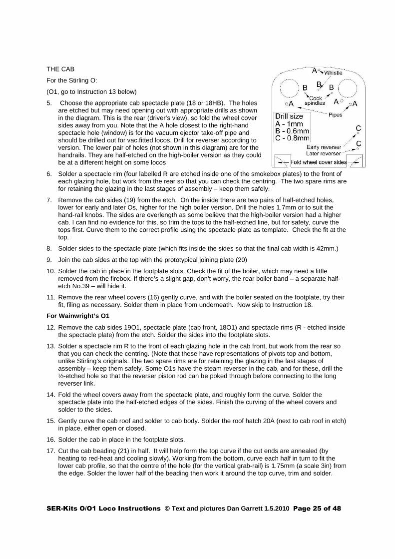
5. Choose the appropriate cab spectacle plate (18 or 18HB). The holes are etched but may need opening out with appropriate drills as shown in the diagram. This is the rear (driver’s view), so fold the wheel cover sides away from you. Note that the A hole closest to the right-hand spectacle hole (window) is for the vacuum ejector take-off pipe and should be drilled out for vac.fitted locos. Drill for reverser according to version. The lower pair of holes (not shown in this diagram) are for the handrails. They are half-etched on the high-boiler version as they could be at a different height on some locos
6. Solder a spectacle rim (four labelled R are etched inside one of the smokebox plates) to the front of each glazing hole, but work from the rear so that you can check the centring. The two spare rims are for retaining the glazing in the last stages of assembly – keep them safely.
7. Remove the cab sides (19) from the etch. On the inside there are two pairs of half-etched holes, lower for early and later Os, higher for the high boiler version. Drill the holes 1.7mm or to suit the hand-rail knobs. The sides are overlength as some believe that the high-boiler version had a higher cab. I can find no evidence for this, so trim the tops to the half-etched line, but for safety, curve the tops first. Curve them to the correct profile using the spectacle plate as template. Check the fit at the top.
8. Solder sides to the spectacle plate (which fits inside the sides so that the final cab width is 42mm.)
9. Join the cab sides at the top with the prototypical joining plate (20)
10. Solder the cab in place in the footplate slots. Check the fit of the boiler, which may need a little removed from the firebox. If there’s a slight gap, don’t worry, the rear boiler band – a separate half-etch No.39 – will hide it.
11. Remove the rear wheel covers (16) gently curve, and with the boiler seated on the footplate, try their fit, filing as necessary. Solder them in place from underneath. Now skip to Instruction 18.
For Wainwright’s O1
12. Remove the cab sides 19O1, spectacle plate (cab front, 18O1) and spectacle rims (R - etched inside the spectacle plate) from the etch. Solder the sides into the footplate slots.
13. Solder a spectacle rim R to the front of each glazing hole in the cab front, but work from the rear so that you can check the centring. (Note that these have representations of pivots top and bottom, unlike Stirling’s originals. The two spare rims are for retaining the glazing in the last stages of assembly – keep them safely. Some O1s have the steam reverser in the cab, and for these, drill the ½-etched hole so that the reverser piston rod can be poked through before connecting to the long reverser link.
14. Fold the wheel covers away from the spectacle plate, and roughly form the curve. Solder the spectacle plate into the half-etched edges of the sides. Finish the curving of the wheel covers and solder to the sides.
15. Gently curve the cab roof and solder to cab body. Solder the roof hatch 20A (next to cab roof in etch) in place, either open or closed.
16. Solder the cab in place in the footplate slots.
17. Cut the cab beading (21) in half. It will help form the top curve if the cut ends are annealed (by heating to red-heat and cooling slowly). Working from the bottom, curve each half in turn to fit the lower cab profile, so that the centre of the hole (for the vertical grab-rail) is 1.75mm (a scale 3in) from the edge. Solder the lower half of the beading then work it around the top curve, trim and solder.

SER-Kits O/O1 Loco Instructions © Text and pictures Dan Garrett 1.5.2010 Page 26 of 48
Stirling cab continued
18. The cab beading (21) has an etched locating groove. It may help first to anneal the part by heating up near to red heat, allowing to cool slowly and then cleaning up. I also find it best to cut the beading into two unequal parts. (Unequal so that the join is not at the top.) Starting from the handrail, bend the first curve, and catch the beading in place with a little solder so that the hole for the grabrail is centred 1.75mm (3 scale inches) away from the cab edge. Now work your way little by little. When you get to the top curve, clamp the beading and gently bend around with fine-nose pliers to fit. Don’t rush ahead - get each part of the curve right before you go on! Then work back on the other side. There’s extra beading to trim off. Finally, round off the edges of the beading.
FRAMES AND CAB WHEEL COVERS
19. Early Os and some O1s had front sandboxes below the footplate, and in this case, the frames (with rivets) can be seen forming the smokebox saddle. They are represented by parts etched inside the early O frames. They should now be soldered in the slots in the footplate.
20. Remove from the etch the wheel-covers and tops (22) which fit inside the cab. For the Os, the covers are each one piece and the sides should be folded down, curved to fit and soldered; For O1s with reverser still in the cab, the lower O wheel covers should be used. For O1s with boiler-side reversers, the wheel covers are in two pieces and higher to form perches for the crew. A 1.4mm hole is best drilled at this stage to take the sanding lever casting on top of the left-hand cover. The pivot and sanding lever are shown as fine dotted lines in the scale drawing showing the cab interior from the side. Using the pivot casting as reference, the hole should be drilled 10.5mm from the front of the wheel-cover, and as close to the fold as possible. For O1s with boiler-side reversers, there is an (?ashpan) lever on the right hand wheel cover and the hole for this should be drilled now.
21. Check that there is clearance between the wheel-covers and wheels, and solder them to the foldup tabs on the footplate. NOTE: I find it easier not to fold the tabs up, but to file them back after soldering.
22. Again, bolt the footplate to the underframe, run the loco and check that the wheels don't touch the wheel-covers on your sharpest curves. Remove footplate from underframe and…
23. Solder together the parts for the steam reverser stand. On the later version and those O1s with the reverser still inside the cab, the stand (27L) is steeply angled and so there is only one end-piece (28L). On the early version, the stand is level, and the two end-pieces (28E) must be curved before soldering to the stand (27E). The completed assembly is soldered to the right-hand splasher inside the cab. (See scale loco drawings)
Section 11: Adding etched detail to the Loco body.
Reversing lever linkage
1. Solder a short piece (~12mm) of 0.7 wire (eg. smokebox handle wire) into the central hole in 30, and fold 30 double to form a forked link.
2. Take the remaining half of the vertical lever 29E or diagonal lever 34L (set aside earlier) and join inside the forked link with a Lill pin. Temporarily place the reverser casting into position on its stand. Feed the wire of the forked link through the hole in the cab front and cut the wire to fit the reverser.. Remove the casting and solder the top half of 29E/34L into position on the footplate so that it corresponds with the lower half of the lever on the chassis. (Make sure the boiler casting has room to slide into place.)
3. Lamp-irons are boxed as 37. Each iron is cranked halfway up (see loco drawing). Two irons should be soldered either side of the smokebox plate. Scale 14" headcode boards are etched with the

SER-Kits O/O1 Loco Instructions © Text and pictures Dan Garrett 1.5.2010 Page 27 of 48
tender (70). The long lamp-iron should have the bottom (rounded end) curled up and is fixed centrally between chimney and smokebox door. (Curling is easier if you file the end thinner.) The curl is to hang the 24" x 18" oval board (etched inside the smoke-box plate, part 70) when the loco is hauling a 'Special'. In SE&CR and SR days, the lamp-irons were moved to the footplate over the buffers, with a additional one over the coupling hook. Check with historical photos.
Sanding levers (not to be confused with the cab castings):
4. In versions with the sandboxes incorporated in the front splashers, there are small but visible levers & cranks in front of the smokebox plate to work the sandboxes. (See also Loco drawing). Fit the etch cranks 25, on the wires fixed to the ogee cylinder cover earlier. A long link (Etch part 26) runs between smokebox and firebox behind the splashers.
The 'wooden' floor 35
5. If you're planning to add the handwheels and brackets 36 for the water supply cocks, first drill out 0.5mm two of the four half-etched holes on the rear of the plate. Early O: the two holes near the middle of the floor; Later O: the two holes near the rear.
Then fold the floor at front and back. (NOTE, the rear fold is diagonal, according to the Ashford drawing and the etch accommodates this. However, as the floor was wooden, it may actually have been cut vertically. This is helpful for modellers, since the footplate flap between loco and and tender is etched wider than scale for modellers who have an over-scale gap for curve clearance. The over-scale flap fouls the diagonal fold. So it's probably best to fold the floor rear vertically, and trim the fold-over.)
Make up handwheels 38 (See Appendix E), fold and thread brackets 36 onto the wire spindles, and solder to the correct height. It’s best to leave the floor and brackets unfixed until after fitting the backhead.
6. Cab Steps. These can be added now, or much later, since there are no castings near them to melt. (If you add them now, you'll have to prop the loco on a block of wood when adding fittings):
7. Choose the appropriate step profiles 25E or L and the corresponding steps 26E or L. Solder the profilesto the locating valley in the rear of the valance beneath the cab. Bend up the rear flanges of the steps (except for the top steps of the Early O, which bend down) and solder into place.
(You may find it best to solder up the tender etches at this stage – Section 13, and then work on white-metal fittings for loco and tender at the same time.)
Section 11: Detailing the Loco (castings)
1. The holes in the buffer beams (7mm either side of the drawhook) are for safety chain eyes. Use either the castings supplied, or cut 4 x 3mm squares of scrap brass (for the square washer plates), drill out 0.6mm and solder over the etched holes. Form 4 'eyes' from 24 SWG wire and solder two of them into the holes. Set aside the remaining washer-plates and eyes for the tender.
2. Vacuum Pipe standard. This can be soldered with low-melt solder underneath the buffer-beam. Because I made a wooden sandwich buffer-beam, I devised a 'pipe-clip' as follows. Cut a piece of scrap brass, bend into an Ω shape to fit the horizontal pipe, drill the sides and pin to the buffer-beam, as in the photo. TIP: this method can also be used with a metal buffer-beam if you prefer not to solder the casting: solder the pipe clip in place, and glue the vac. pipe into place after painting.
3. Buffers. Check that the buffers slide freely and superglue the nuts to the spindles. Glue the buffers in place on the buffer beam, with just enough glue. (Too much and the buffers may lock solid!)
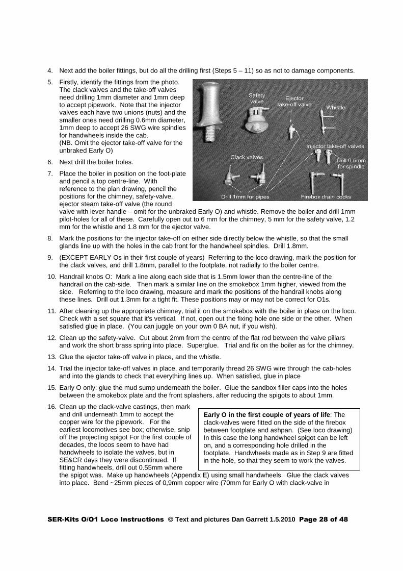
SER-Kits O/O1 Loco Instructions © Text and pictures Dan Garrett 1.5.2010 Page 28 of 48
Early O in the first couple of years of life : The clack-valves were fitted on the side of the firebox between footplate and ashpan. (See loco drawing) In this case the long handwheel spigot can be left on, and a corresponding hole drilled in the footplate. Handwheels made as in Step 9 are fitted in the hole, so that they seem to work the valves.
4. Next add the boiler fittings, but do all the drilling first (Steps 5 – 11) so as not to damage components.
5. Firstly, identify the fittings from the photo. The clack valves and the take-off valves need drilling 1mm diameter and 1mm deep to accept pipework. Note that the injector valves each have two unions (nuts) and the smaller ones need drilling 0.6mm diameter, 1mm deep to accept 26 SWG wire spindles for handwheels inside the cab. (NB. Omit the ejector take-off valve for the unbraked Early O)
6. Next drill the boiler holes.
7. Place the boiler in position on the foot-plate and pencil a top centre-line. With reference to the plan drawing, pencil the positions for the chimney, safety-valve, ejector steam take-off valve (the round valve with lever-handle – omit for the unbraked Early O) and whistle. Remove the boiler and drill 1mm pilot-holes for all of these. Carefully open out to 6 mm for the chimney, 5 mm for the safety valve, 1.2 mm for the whistle and 1.8 mm for the ejector valve.
8. Mark the positions for the injector take-off on either side directly below the whistle, so that the small glands line up with the holes in the cab front for the handwheel spindles. Drill 1.8mm.
9. (EXCEPT EARLY Os in their first couple of years) Referring to the loco drawing, mark the position for the clack valves, and drill 1.8mm, parallel to the footplate, not radially to the boiler centre.
10. Handrail knobs O: Mark a line along each side that is 1.5mm lower than the centre-line of the handrail on the cab-side. Then mark a similar line on the smokebox 1mm higher, viewed from the side. Referring to the loco drawing, measure and mark the positions of the handrail knobs along these lines. Drill out 1.3mm for a tight fit. These positions may or may not be correct for O1s.
11. After cleaning up the appropriate chimney, trial it on the smokebox with the boiler in place on the loco. Check with a set square that it's vertical. If not, open out the fixing hole one side or the other. When satisfied glue in place. (You can juggle on your own 0 BA nut, if you wish).
12. Clean up the safety-valve. Cut about 2mm from the centre of the flat rod between the valve pillars and work the short brass spring into place. Superglue. Trial and fix on the boiler as for the chimney.
13. Glue the ejector take-off valve in place, and the whistle.
14. Trial the injector take-off valves in place, and temporarily thread 26 SWG wire through the cab-holes and into the glands to check that everything lines up. When satisfied, glue in place
15. Early O only: glue the mud sump underneath the boiler. Glue the sandbox filler caps into the holes between the smokebox plate and the front splashers, after reducing the spigots to about 1mm.
16. Clean up the clack-valve castings, then mark and drill underneath 1mm to accept the copper wire for the pipework. For the earliest locomotives see box; otherwise, snip off the projecting spigot For the first couple of decades, the locos seem to have had handwheels to isolate the valves, but in SE&CR days they were discontinued. If fitting handwheels, drill out 0.55mm where the spigot was. Make up handwheels (Appendix E) using small handwheels. Glue the clack valves into place. Bend ~25mm pieces of 0,9mm copper wire (70mm for Early O with clack-valve in
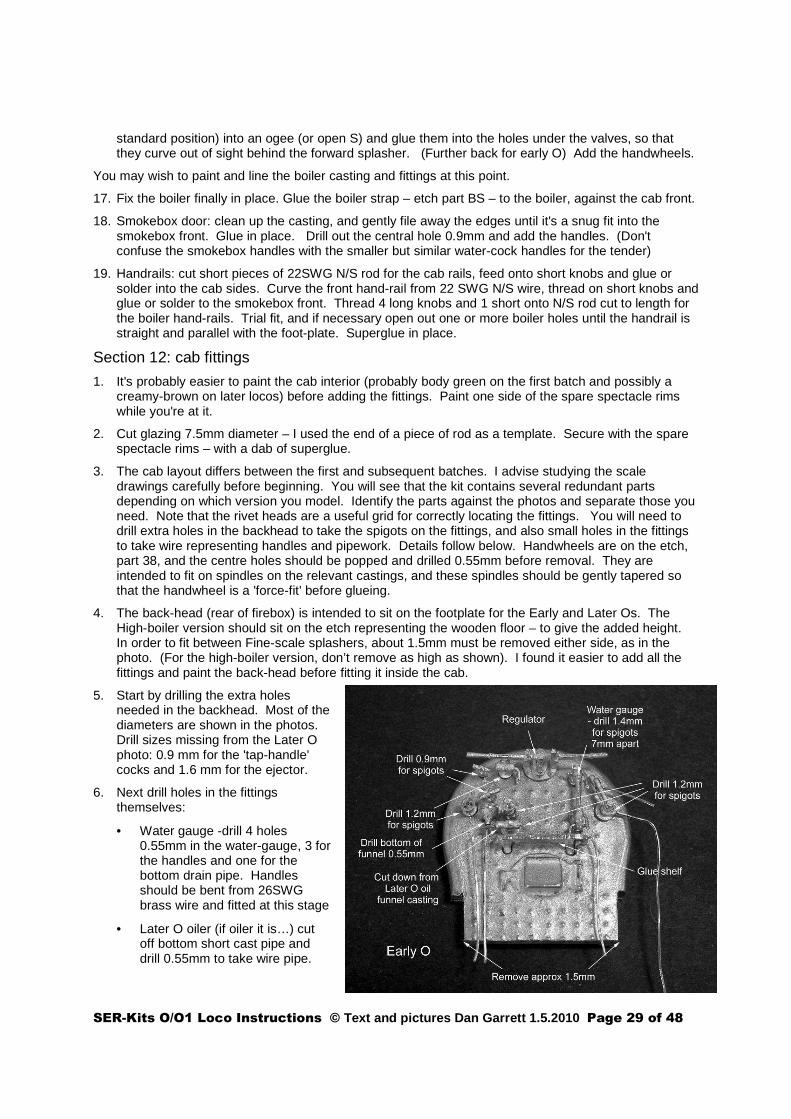
SER-Kits O/O1 Loco Instructions © Text and pictures Dan Garrett 1.5.2010 Page 29 of 48
standard position) into an ogee (or open S) and glue them into the holes under the valves, so that they curve out of sight behind the forward splasher. (Further back for early O) Add the handwheels.
You may wish to paint and line the boiler casting and fittings at this point.
17. Fix the boiler finally in place. Glue the boiler strap – etch part BS – to the boiler, against the cab front.
18. Smokebox door: clean up the casting, and gently file away the edges until it's a snug fit into the smokebox front. Glue in place. Drill out the central hole 0.9mm and add the handles. (Don't confuse the smokebox handles with the smaller but similar water-cock handles for the tender)
19. Handrails: cut short pieces of 22SWG N/S rod for the cab rails, feed onto short knobs and glue or solder into the cab sides. Curve the front hand-rail from 22 SWG N/S wire, thread on short knobs and glue or solder to the smokebox front. Thread 4 long knobs and 1 short onto N/S rod cut to length for the boiler hand-rails. Trial fit, and if necessary open out one or more boiler holes until the handrail is straight and parallel with the foot-plate. Superglue in place.
Section 12: cab fittings
1. It's probably easier to paint the cab interior (probably body green on the first batch and possibly a creamy-brown on later locos) before adding the fittings. Paint one side of the spare spectacle rims while you're at it.
2. Cut glazing 7.5mm diameter – I used the end of a piece of rod as a template. Secure with the spare spectacle rims – with a dab of superglue.
3. The cab layout differs between the first and subsequent batches. I advise studying the scale drawings carefully before beginning. You will see that the kit contains several redundant parts depending on which version you model. Identify the parts against the photos and separate those you need. Note that the rivet heads are a useful grid for correctly locating the fittings. You will need to drill extra holes in the backhead to take the spigots on the fittings, and also small holes in the fittings to take wire representing handles and pipework. Details follow below. Handwheels are on the etch, part 38, and the centre holes should be popped and drilled 0.55mm before removal. They are intended to fit on spindles on the relevant castings, and these spindles should be gently tapered so that the handwheel is a 'force-fit' before glueing.
4. The back-head (rear of firebox) is intended to sit on the footplate for the Early and Later Os. The High-boiler version should sit on the etch representing the wooden floor – to give the added height. In order to fit between Fine-scale splashers, about 1.5mm must be removed either side, as in the photo. (For the high-boiler version, don’t remove as high as shown). I found it easier to add all the fittings and paint the back-head before fitting it inside the cab.
5. Start by drilling the extra holes needed in the backhead. Most of the diameters are shown in the photos. Drill sizes missing from the Later O photo: 0.9 mm for the 'tap-handle' cocks and 1.6 mm for the ejector.
6. Next drill holes in the fittings themselves:
• Water gauge -drill 4 holes 0.55mm in the water-gauge, 3 for the handles and one for the bottom drain pipe. Handles should be bent from 26SWG brass wire and fitted at this stage
• Later O oiler (if oiler it is…) cut off bottom short cast pipe and drill 0.55mm to take wire pipe.
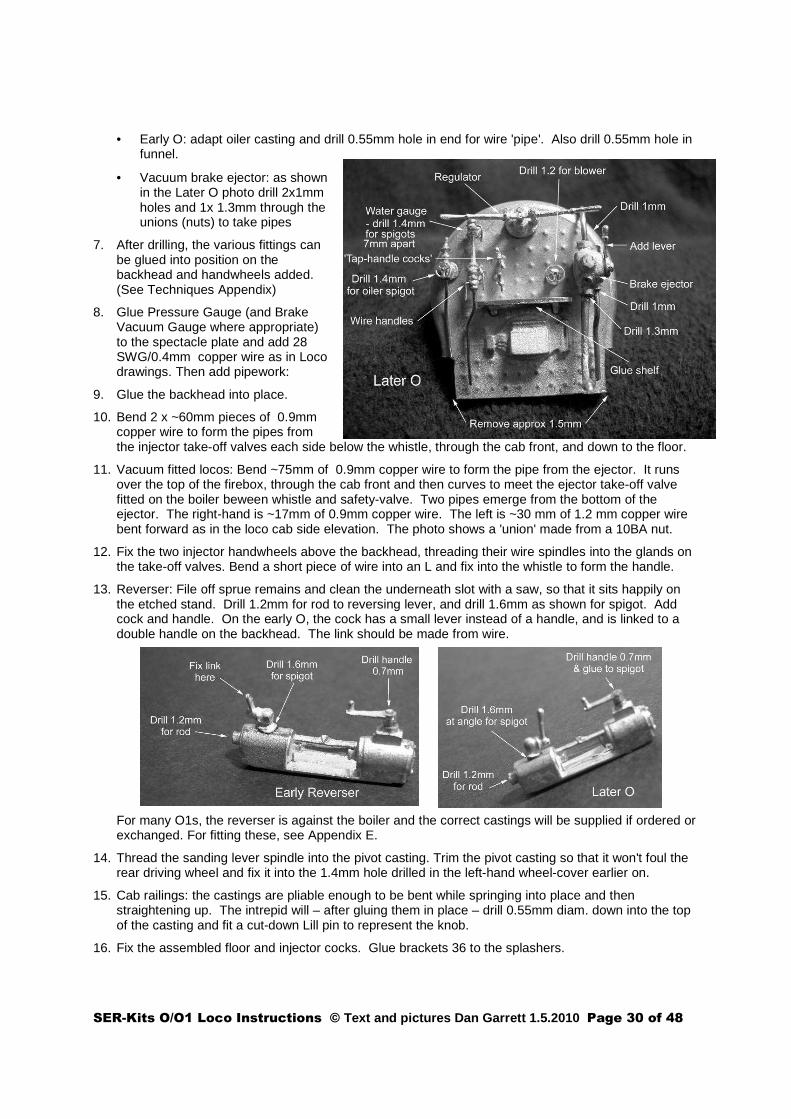
SER-Kits O/O1 Loco Instructions © Text and pictures Dan Garrett 1.5.2010 Page 30 of 48
• Early O: adapt oiler casting and drill 0.55mm hole in end for wire 'pipe'. Also drill 0.55mm hole in funnel.
• Vacuum brake ejector: as shown in the Later O photo drill 2x1mm holes and 1x 1.3mm through the unions (nuts) to take pipes
7. After drilling, the various fittings can be glued into position on the backhead and handwheels added. (See Techniques Appendix)
8. Glue Pressure Gauge (and Brake Vacuum Gauge where appropriate) to the spectacle plate and add 28 SWG/0.4mm copper wire as in Loco drawings. Then add pipework:
9. Glue the backhead into place.
10. Bend 2 x ~60mm pieces of 0.9mm copper wire to form the pipes from the injector take-off valves each side below the whistle, through the cab front, and down to the floor.
11. Vacuum fitted locos: Bend ~75mm of 0.9mm copper wire to form the pipe from the ejector. It runs over the top of the firebox, through the cab front and then curves to meet the ejector take-off valve fitted on the boiler beween whistle and safety-valve. Two pipes emerge from the bottom of the ejector. The right-hand is ~17mm of 0.9mm copper wire. The left is ~30 mm of 1.2 mm copper wire bent forward as in the loco cab side elevation. The photo shows a 'union' made from a 10BA nut.
12. Fix the two injector handwheels above the backhead, threading their wire spindles into the glands on the take-off valves. Bend a short piece of wire into an L and fix into the whistle to form the handle.
13. Reverser: File off sprue remains and clean the underneath slot with a saw, so that it sits happily on the etched stand. Drill 1.2mm for rod to reversing lever, and drill 1.6mm as shown for spigot. Add cock and handle. On the early O, the cock has a small lever instead of a handle, and is linked to a double handle on the backhead. The link should be made from wire.
For many O1s, the reverser is against the boiler and the correct castings will be supplied if ordered or exchanged. For fitting these, see Appendix E.
14. Thread the sanding lever spindle into the pivot casting. Trim the pivot casting so that it won't foul the rear driving wheel and fix it into the 1.4mm hole drilled in the left-hand wheel-cover earlier on.
15. Cab railings: the castings are pliable enough to be bent while springing into place and then straightening up. The intrepid will – after gluing them in place – drill 0.55mm diam. down into the top of the casting and fit a cut-down Lill pin to represent the knob.
16. Fix the assembled floor and injector cocks. Glue brackets 36 to the splashers.
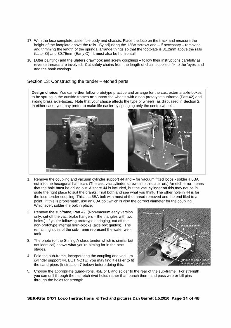
SER-Kits O/O1 Loco Instructions © Text and pictures Dan Garrett 1.5.2010 Page 31 of 48
Design choic e: You can either follow prototype practice and arrange for the cast external axle-boxes to be sprung.in the outside frames or support the wheels with a non-prototype subframe (Part 42) and sliding brass axle-boxes. Note that your choice affects the type of wheels, as discussed in Section 2. In either case, you may prefer to make life easier by springing only the centre wheels.
17. With the loco complete, assemble body and chassis. Place the loco on the track and measure the height of the footplate above the rails. By adjusting the 12BA screws and – if necessary – removing and trimming the length of the springs, arrange things so that the footplate is 31.2mm above the rails (Later O) and 30.75mm (Early O). It must also be horizontal!
18. (After painting) add the Slaters drawhook and screw couplings – follow their instructions carefully as reverse threads are involved. Cut safety chains from the length of chain supplied, fix to the 'eyes' and add the hook castings.
Section 13: Constructing the tender – etched parts
1. Remove the coupling and vacuum cylinder support 44 and – for vacuum fitted locos - solder a 6BA nut into the hexagonal half-etch. (The cast vac cylinder screws into this later on.) An etch error means that the hole must be drilled out. A spare 44 is included, but the vac. cylinder on this may not be in quite the right place to suit the cranks. Trial both and see what you think. The other hole in 44 is for the loco-tender coupling. This is a 6BA bolt with most of the thread removed and the end filed to a point. If this is problematic, use an 8BA bolt which is also the correct diameter for the coupling. Whichever, solder the bolt in place.
2. Remove the subframe, Part 42. (Non-vacuum early version only: cut off the vac. brake hangers – the triangles with two holes.) If you’re following prototype springing, cut off the non-prototype internal horn-blocks (axle box guides). The remaining sides of the sub-frame represent the water well-tank.
3. The photo (of the Stirling A class tender which is similar but not identical) shows what you’re aiming for in the next stages.
4. Fold the sub-frame, incorporating the coupling and vacuum cylinder support 44. BUT NOTE: You may find it easier to fit the sand-pipes (Instruction 7 below) before doing this.
5. Choose the appropriate guard-irons, 45E or L and solder to the rear of the sub-frame. For strength you can drill through the half-etch rivet holes rather than punch them, and pass wire or Lill pins through the holes for strength.

SER-Kits O/O1 Loco Instructions © Text and pictures Dan Garrett 1.5.2010 Page 32 of 48
Painting and lining tenders with springs above the footplate can be a problem. The kit is designed to make the tender body removable from the footplate.
6. Cut a piece of 1/16” brass rod a little wider than the sub-frame to form the vac. crank spindle. Thread the vac. crank 64 onto it, and solder the spindle into the vac. brake hangers allowing the crank to remain free.
7. Form the sand-pipes from 2x 36mm lengths of 19SWG copper wire, bent at right-angles 10mm from one end. Thread the short ends through the holes in the sides of the sub-frame and solder in place.
8. Internal sub-frame springing only: Treat the axle-box guides 43 as for the loco by cutting a thread in the tags and bending them up. Solder them in place, inside the subframe, using the etch lines as guides. Partially screw in 12 BA bolts– they can be adjusted through the semi-circular cut-outs. The photo shows what all this will eventually look like.
9. Choose the appropriate pair of frames, 46E or 46L. Attached to the front of each etch is a small oval or circle with etched bolts, and a washer. Remove these, and sweat or superglue the first to the outside of the frame and the washer inside to make the main brake rod bearing, locating with a matchstick.
10. Punch all the other rivet holes from the rear. However, if you look at the drawings and photos, you will see that the prototype spring hangers are fixed to rods with quite large flattened heads. These are catered for in the half-etched rivet positions, but you will need a larger, flatter punch. An alternative is to drill the centre of these holes and – later on – fix the spring hanger castings with pins with suitably large heads. Bend the axle-box guides outwards.
11. Remove the footplate 48, taking care with the ½ etch edges
12. Solder the frames in place – make sure to get them the right way round! Solder the front and rear buffer beams (49 E or L and 50) after punching rivet holes. NOTE: The holes in the front beam are prototype holes, and if you are using the loco-tender coupling supplied, remove the half-etches to make one long slot.
13. Solder the drawhook washer plate 51E or L onto the rear buffer beam, locating it by the drawhook slots. Remove ½ mm extra overhang from rear of footplate if you want to be exact.
14. Sweat the beading 52 to the frames underneath the footplate on each side. Note that the returns are uneven, so match carefully to buffer beams before soldering.
15. Prototype sprung external axleboxes only: There are six tags (Etch Part 47) to guide the axle-box spigots. Cut them out, run a 1.2 mm drill through each hole, and bend them along the etch line. Solder each tag into the ½ etch rectangles behind the frames above each axlebox.
16. There are 6BA hexagonal half-etches on the top of the footplate but only for non-removable tanks.
17. Take the steps 60E or L and fold up the fixing tab, except for the upper steps of the early version, where you fold DOWN. Solder the steps in place.
18. Remove the water tank 52 and drill out the appropriate holes for the handrail knobs – they are labelled L or R on the etch, the side with the fold lines, but for safety check with the scale drawing and against photos. The holes should usually be 1.3mm unless the supplier changes the diameter.

SER-Kits O/O1 Loco Instructions © Text and pictures Dan Garrett 1.5.2010 Page 33 of 48
19. Early O only: The tank is shorter than later versions, so cut the rear back to and including the half-etch line on the underside of the etch – 5mm. File back the front of the tank top by 1.4mm (using the underneath half-etch as a guide). The tank top (early O) should now be 91mm long.
20. The tender rear (52 rear) has tabs to fit the corresponding slots on the sides. For the shorter early O you will need to file off the tabs. Fold the tank into a box and solder the rear into place
21. Trial the tank on the footplate and note that etched slots allow it to move backwards or forwards by 1mm. Slide forwards for the early version and backwards for the later version.
22. Locate the tank front (52 front) into its slots in the footplate and clamp between the tank sides. Remove tank from footplate and solder the front in place. Solder lengths of scrap brass to each side of the tank to support the tank front. (They can be seen in the photo below.).
23. Take the bunker front 54 and fold back the top edge. Take the shovelling-plate 55 and check that the front 'tongue' fits through the hole in 54. Ease them into place between the bunker sides and solder the bunker front. Assuming you want a removable tender body, do not solder the shovelling plate yet. If you’re building an O1, read Appendix F about different parts to be soldered before continuing.
REMOVABLE TENDER BODY
24. There is a cross-piece (73) with a half-etch to take a 6BA nut. Use this if you wish to make the tank removable. Solder the nut, and spring the stretcher into the half etched slots inside the tank. NOTE: The nut is off-centre, and by rotating the stretcher it will be above the fixing hole in the footplate whether you are building the earlier or later versions. Check this, and solder the stretcher in place.
25. Fix the shovelling plate at less of an angle so that there is room for a 6BA nut without lifting the body off the footplate. Place the body in position on the footplate, turn the tender upside down, and mark through the existing hole. Drill through, clearance for 6BA. Solder the nut in place.
26. When assembling, 6BA bolts pass through sub-frame, chassis and tank.
27. Sweat the coal-door 60 into place, referring to the drawing.
28. Choose the appropriate side flares 61E or L and the end flare 62. Curve them over a piece of 6mm (¼") rod (as in the photo) working backwards and forwards a little bit at a time. Do not attempt to bend right over in one go or there'll be a lot of distortion. Sweat them in place to just cover the half-etch guidelines.
29. Joggle and solder the lamp-irons in place on the back of the tender. As with the loco, in SER days they are on the body – the tank – and from SECR days are on the footplate. You may wish to leave soldering the projecting top centre lamp-iron until after fitting the brakes and castings as it's vulnerable. It's far enough from the castings for heat not to be a problem (unless you dwell for ages with the iron.
30. Early version: Solder the tender cock brackets 68 to the front of the bunker, as in the loco drawing. Later versions: Solder short pieces of wire in the tiny holes in the bunker front fold for the water cock handles.

SER-Kits O/O1 Loco Instructions © Text and pictures Dan Garrett 1.5.2010 Page 34 of 48
31. Refer to the scale drawing and to photographs of your chosen loco, and determine the position of the water tank filler. Open out the etched hole to 6.5 mm. Different castings are supplied for E & L locos.
32. Tank-top toolbox: the early O had a small version, the later O a larger one. The latter is on the etch, 68 to be folded for the sides and 69 to be partially folded for the top. Position according to the drawing, but check with photos. The small toolbox is supplied as casting if you have pre-ordered, as is the early O’s rear toolbox (which goes behind the shorter tank).
33. Make up the front sandboxes (most locos, but not all O1s) from parts 76 the tops, and 77 the sides. Early Os had filler caps, supplied as castings, and are best fitted if a hole is drilled first as shown in the plan drawing. Roll the sides to fit the ½-etch of the tops and solder to the bunker front and tender sides, but (obviously..?) not to the floor if the body is to be removable.
34. Fold the steps 53 as for the loco and solder into the ½-etches on the side frames. When drawing the etch art-work, I hadn’t noticed the steps fitted to the tender rear of many O1s. Use some of the spare O steps.
35. Soldering on the tender body is now virtually complete.
Section 14: Springing loco & tender, adjusting the running, and fitting tender brakes
For the non-prototype internal bearing method, follow instructions 1 - 3. Follow instructions 4 to 9 for sprung axleboxes. Note that you may well not need to spring all 6 wheels. One of my tenders has fixed front & rear axles, and only the middle one is sprung. It seems to run as well as the fully-sprung tenders. (However my layout is Finescale not S7)
1. Cut 4 x 6.5mm springs and 2 x 6mm from the 2.4 diam phosphor-bronze spring. Work the springs between the adjusting bolts and the axleboxes. (shorter springs in middle) Add wheels and axles to the sub-frame, packing with washers as necessary. It's best to have no side-play on the rear wheels, a little on the front, and most on the middle axle. Run the sub-frame around your tightest curve, and re-pack the washers as necessary.
2. Rest the tender body on the subframe, and load the tender with the bigger castings – toolbox (where appropriate) and filler cap – in the correct position. By adjusting the 12BA screws and – if necessary – removing and trimming the length of the springs, arrange things so that the footplate is 31.25mm above the rails (Later O), 30.75mm (Early O) and horizontal!. Add the loco-tender coupling (Etch part 12) – see earlier diagram. Couple up, and have a trial run round. Check the distance between loco and tender against the drawing, and – depending on the sharpness of your curves, you may wish to close the gap a little by putting a joggle in the coupling.
3. Bend back the etched keeper plates and fit the cast (external) axleboxes. Glue in place
Sprung Axleboxes
4. Clean up the axle-box castings, so that they slide freely in the guides in the brass frames. The spigot may be bent if necessary with fine-nosed pliers into a slight dog-leg so that it slides easily up and down in the tag 47. However on uneven track it’s possible for the spigot to pop out. One solution is to bend the tags slightly down. Better still, cut the rod off, drill a hole and replace with wire rod a bit longer than the original.
5. Before going any further, cut springs from the stiffer of the fine springs (1.6mm diam, and stiffer than the plunger pick-up spring). On my tender, the springs were – from front to rear – 5.5mm, 5mm, 5.5mm. The springs ping easily and dematerialise, so I find it easiest to clamp an axle-box gently in the vice, feed the end of the spring onto the spigot and cut it to length with a pair of fine scissors. Put the springs into a tin-lid where they won't get lost.
6. Axle by axle, check the wheel-sets fit and rotate freely. The axle-boxes are cast with holes to take Slaters 0.1" top-hat wagon wheel bearings, and I use these for Slaters MF wheelsets. (Yes I know these don't have needle bearings, but it seems to make no noticeable difference.) Provided the bearings are pushed home, the holes will probably need no further drilling for a snug fit. However, to get the tender round sharp curves the middle axle-box holes may need to be drilled out a further ½ -

SER-Kits O/O1 Loco Instructions © Text and pictures Dan Garrett 1.5.2010 Page 35 of 48
¾ mm with a 2.5mm drill. Make sure there is virtually no side play on the rear axle, to minimise the risk of buffer-lock. If you have very sharp curves, it may help to allow some play on the front wheels.
7. Fitting the springs can be ticklish, but this method works for me: with the wheel-sets still in place, lay the tender on its side, ease one of the axle-boxes out, until there is enough room to fit a spring held in tweezers, as in the photo on the next page. Ease the axle-box carefully back in, making sure the spigot goes correctly into the tag-hole. Bend the keeper plate partially back into positon to prevent the axle-box falling out. Repeat for the other axle-boxes.
8. Sprung this way, the tender should - once the castings have been fitted - sit on the track at the correct scale height, 31.2mm above the rails (Later O), 30.75mm (Early O). Make sure it's horizontal!
9. If height adjustment should prove to be needed, then the axleboxes will have to removed and the springs cut shorter or stretched slightly. Once you’re satisfied, then bend and glue the keeper plates into position. If you have to do lots of adjustment, the danger is that the keeper plates will break away. If this happens, all is not lost. Drill through the rivets and frames 0.6mm and secure the keeper plates in position with pins soldered or glued.
Then, whichever method you’re using:
10. Add the loco-tender coupling (Etch part 12) – see earlier diagram. Couple up, and have a trial run round. Check the distance between loco and tender against the drawing, and – depending on the sharpness of your curves, you may be able to close the gap a little by putting a joggle in the coupling.
Making up the brakes:
WARNING: If you're using sprung axleboxes as in the prototype, make sure the tender height is finalised at this stage. Once the brake gear is fitted, adjusting the springs will require major surgery!
21. (Vac. fitted versions only) Drill 1/16" (1.6mm) into the bottom of the vacuum cylinder casting to take the vac. piston rod, and screw the casting into hole & 6BA nut in the sub-frame support, part 44.
22. Cut a 46.5mm length of 1/16" (1.6mm) brass rod as the main brake crank spindle. Thread on: the brake handle link 65, one tiny crank (either the casting or the etch 41), and (vac. fitted versions) the composite crank for the vac cylinder 64, followed by the final tiny crank. (As the photo. The brake handle link goes on left hand (fireman’s) side of the tender:)
23. Pop the rod into the bearings in the frames. You should bend over the brake handle link and solder to the floor, but do not solder the other end to the brake spindle - then you can disassemble the tender if necessary.
24. (vac. fitted versions only) Cut a 25mm length of 3/64" (1.2mm) diam. brass rod, thread through the remaining hole in the vacuum bell crank 64 and into the holes in the the vac. brake hangers (see photo in Section 13, instr). The bell crank extension should be located into the drilled hole in the vacuum cylinder. These last items can be soldered or glued into place (but bear in mind any later disassembly you may wish to carry out.)

SER-Kits O/O1 Loco Instructions © Text and pictures Dan Garrett 1.5.2010 Page 36 of 48
25. Early version only: For wheels in sub-frame hornblocks, lengths of 1mm wire should be threaded through the holes in the subframe, with the cast ('wooden') brake blocks threaded on. For Martin Finney wheels in axleboxes (no subframe hornblocks – as photo) the brake hangers can be soldered or glued into the holes in the tender footplate. The brakes are coupled to each other and to the small cranks 63 by the long, brake rods with adjusting holes 66. It is possible that these rods were doubled up behind the wheels, as with Cudworth locos, and if this is the case, you will need to make your own from strip using the etches as templates. The brake shoes are coupled in pairs by transverse 32.5mm ‘cross-rods’ cut from 3/64” brass tube. (The centre tube should be a little longer if you need the centre wheels to have considerable play to get round your curves) A lill pin is threaded through the brake rod 66, into the hole in each brake block, and then glued into the tube.
26. Now go to the next section.
Vacuum-fitted versions – complete as follows:
27. Drill through 0.9mm the cast 'bolts' holding brake blocks to hangers.
28. Glue the tops of the hangers into the rectangular holes in the footplate. When set, link the brakes, following the same approach as for the loco. NOTE, however, that in the prototype the linkage is doubled up behind the wheels. This can be seen on the preserved O1 on the Bluebell Railway. The kit has enough etched links for doubling up, but if you want an easier life, with fewer short-circuits, you may wish to omit the inner linkage. The photo and instructions assume this is what you will do!
29. These brakes are etched as Box 67. Use the curved link to connect the rear brake block to the bottom hole of a 3-hole link pinned to the centre brake block. The straight link connects the middle hole of the middle 3-hole link to the bottom hole of the front 3-hole link. The ‘bobbly’ adjuster link 67 runs from the middle hole of the front 3-hole link to the tiny cranks 41. You can replace the etched ‘bobble’ with the casting to represent the prototype collar, nut and bolt. (In real life, the bolt is screwed in or out to move the collar along the slot.
30. The brake shoes are coupled in pairs by ‘cross-rods’ cut from 3/64” brass tube. (The length seems to be 32.5mm, but check it for yourself. The centre rod should be a little longer if you need the centre wheels to have considerable play to get round your curves) A lill pin is threaded through each brake rod, through the top hole of the 3-hole link into the hole in each brake block, and then glued into the tube.

SER-Kits O/O1 Loco Instructions © Text and pictures Dan Garrett 1.5.2010 Page 37 of 48
Section 15: Tender fittings
1. Glue the rear buffers in position.
2. Gently part the forks of the cast spring-hangers, and then pinch a cast spring in place between each pair.
3. Early Os: The centre rod to the axlebox is passed through a little rectangular housing, and the springs are set higher than on the later Os. So first, glue all 6 housings to the footplate. Cut down the centre rod on all the springs, and file a taper to fit into the top of the rectangular housing.
4. Later Os: Thread each spring & hanger set into the rectangular etched holes in the footplate.
5. Both versions: Glue the spring in place (via the rod to the axlebox) but don't glue the hangers at this stage. A piece of 10 thou styrene sheet will help keep the spring at the correct distance away from the side. Carefully check the alignment by looking along the tops of the hangers before the glue is set. (I have drilled out the ‘bearings’ to fit pins with flattened heads, but this is not necessary if you’ve punched the half-etch circles on the rear.)
6. Vacuum Pipe standard: bend the bottom pipe back on itself (it's OK – the metal can survive this!) so that it can wrap around the rear buffer beam and be soldered (with low-melt) or glued at the rear.
7. Make up the Slater’s draw-hook (coupling hook) and fix in place.
8. Fix the water-tank filler, again noting that its position can vary.

SER-Kits O/O1 Loco Instructions © Text and pictures Dan Garrett 1.5.2010 Page 38 of 48
9. Fitting the railings. The kit offers two possible methods: the castings supplied or solder up your own. The castings are to scale, and cast in a pliable alloy. Fixed as instructed below, they are quite strong, and if they’re bent by handling, can be bent back without snapping. The alternative method is for you to solder everything up from N/S rod using the etched railing tops (78). This of course will not have the profiling of the casting, but may survive rougher handling.
10. Railing castings. Drill 2 holes 0.5 mm diam into each bracket, locate the casting, and use these holes as a guide to drill through the side. Solder 26 SWG wire (or the ends of cut-down Lill pins) into the holes and cut flush on the inside, leaving 1mm or so projecting on the outside. The castings can be glued to these pins after painting is complete.
Water cocks
11. Glue the tiny cast handles onto the wires soldered previously into the holes on the turnover of the bunker top.
12. (Early version) The mechanisms are in little housings on either side of the top of the water tank – see scale drawing. Glue the relevant castings in place. The rods from the cocks are protected by long housings also represented by castings which are to be glued below the flares. Before doing so, drill the ends 0.55mm and add handles bent from 24 SWG wire.
13. The fall-plate - flap linking loco and tender footplates - part 79, should have shortened Lill pins soldered into the holes in the outermost oval hinges. The other hinges have rear ½-etches to press as ‘rivet’ heads. The pins drop into corresponding holes in the tender etch, after loco and tender have been coupled. Depending on the sharpness of your curves, you may need to re-profile the front of the flap so as to clear the cab floor and railings.
14. SER/SE&CR: Add safety-chain eyes to loco and tender buffer beams. Cut the chain into 4 pieces of 6 links. Open out the end links and fix hooks, and then fix to the eyes. In service, the hooks were usually tucked into the eyes leaving a loop of chain hanging down. Glue them in this position for ease of coupling.
Appendix A: Wooden Sandwich Buffer Beams
1. Cut the front and rear of the buffer beam from the composite etch. Discard the sides.
2. Solder the rear of the buffer beam into place against the valances, and solder the central strengthening plate to the front of the buffer beam..
3. Cut a small piece of hardwood 3mm thick to the same height as the buffer beam and about ¾ mm wider. (See photographs) Epoxy resin glue the hardwood to the front buffer beam.
4. Continue assembling the locomotive. When all soldering is complete, and you reach the instructions for fitting the buffers, carry out the following.
5. (Assuming the resin glue is well set), drill through the wood using the holes in the front of the buffer beam as a guide. Then, from the rear, carefully open the holes out, taking care not to drill through the brass. Also drill out the draw-hook hole. Glue the buffers in place, making sure they move freely. When set, glue the assembly to the rear buffer beam already soldered to the loco.
Appendix B: Troubleshooting Wheel Binding: 1. First, check that the worm and worm-wheel mesh smoothly. Any problem is most likely to occur with
a self-assembly gear-box. Sadly, not all worm-wheels are concentric on the axle, and can result in a jerky 'chuff-chuff-chuff' movement. Running the motor without gear lubricant for an hour or two usually cures this, but on occasion I've had to smear valve-grinding paste on the worm-wheel and run for several minutes. If you resort to this, take the motor out of the chasiss, and be sure to clean off all the paste with white spirit before re-assembly.

SER-Kits O/O1 Loco Instructions © Text and pictures Dan Garrett 1.5.2010 Page 39 of 48
2. Secondly, check that all your axles are parallel and at right-angles to the sides of the chassis. Maybe when soldering the axle-box guides you forced one or more of the axles out of alignment. If necessary, disassemble the chassis, put the soldering iron on the offending axle-box guide and move it slightly. Re-check that the axles are parallel and at right-angles to the sides of the chassis, re-assemble and try the coupling-rods again.
3. If binding still occurs it will show most when the cranks on one side are horizontal. By feeling and looking at the bearings, work out whether the coupling rod is trying to force the wheel bearings apart or closer together – in other words are the bearings on the coupling rod set too close or too distant? (It may help to separate the coupling rod halves, and try the front pair on their own.) Once you are sure of the problem, remove the offending coupling rod, unsolder the bearing, and file the coupling-rod hole to a very slight oval in the appropriate direction. Re-solder the bearing and trial again.
Appendix C: Techniques • Punching Rivet Holes
If you don't have one of those expensive riveting tools, use a centre-punch or 1/16" steel rod turned to a point. Place the etch face down on the end-grain of a piece of wood or old leather belt, and punch each half-etched rivet with a light tap of the hammer.
• Folding etches
As with all etched kits, folds should be made so that the half-etch fold line ends up inside the fold. Fold in the vice or pinch between metal bars. Reinforce the fold with a narrow fillet of solder.
• Soldering
It helps to have solder of different melting points, using the high melting point solder first. If you only use one type of solder, there is a danger that previously soldered parts will move when a later component is soldered in place.
Use a good flux for the metal etch – Carr's Green Label for example. But wash the assembly at the end of each modelling session to avoid corrosion.
Solder paint is helpful for small parts, especially if used in conjunction with a resistance soldering probe. (Although expensive, a resistance soldering unit makes assembly of brass etch kits much easier)
• Making up hand-wheels: best done before removing from etch: drill the handwheel centres 0.5mm. Hold ~15mm of 26SWG in the vice, and - holding the complete handwheel etch - solder the handwheel to the wire. Snip from etch and clean up.
• Fixing Low-melting Point Alloy (LMA) Castings
In general, I recommend fixing detail parts with either 2-part epoxy resin adhesive (Devcon, Araldite, etc) or one of the many superglues.
Many of the castings use a low-melt alloy which reproduces detail well but whose melting point is only a little higher than low-melt solders. Hence my advice against using low melting point solders. Most of the white metal parts are designed with spigots which fix into holes in the loco and tender bodies.

SER-Kits O/O1 Loco Instructions © Text and pictures Dan Garrett 1.5.2010 Page 40 of 48
Appendix D – Boiler side reverser for many O1s
19. O1 with reverser against boiler. The diagram shows the general arrangement. All the castings are provided, but the exact positioning varies according to locomotive, so check with photographs. The photo shows a model R class with similar SER-Kits castings on the tank front. In conjunction with the drawing and your own photos, it should give you a fair idea of what you’re aiming for. Careful drilling is needed and you may wish to omit some of the control rods and pipework.
20. Trial the reverser casting beside the boiler. In the photo, the Reverser steam take-off casting is the one at the top of the photo. This needs drilling as below.
21. DRILLING: The lever on the lower (steam) cylinder is intended to be connected by a rod to the lever on the Reverser Steam Take-off casting. The control rod for the latter rotates (on the prototype) and is pivoted in the casting. This is the trickiest bit of drilling, and I suggest cutting off the lever on the Steam Take-off casting and drilling it separately (the holes (against the double arrow) are best 3mm apart. Later on, the lever can be glued to the 0.5mm control rod and connected to the steam valve. To hold the rod, drill 0.55mm into the Take-off casting. The photo shows a tank-front reverser, but the hole sizes are the same.
22. The copper pipe connecting the Reverser Steam Take-off to the valve on the top cylinder is not yet fitted in the first photo. It’s quite distinctive and curved in a variety of ways on different locos, so check with photos. Use 24 SWG 0.55mm copper.
23. The levers on the main reverser casting are slightly overscale to allow for drilling and could be thinned down afterwards.
Appendix E: O1 Tenders
1. As these locomotives lasted and so long (with one remaining on the Bluebell Railway) there are so many tender variations that the modeller must work from photos of the chosen prototype. The etch has a number of possibilities as follows.
2. Once the bunker front has been fitted, most O1s will need a bunker top 70 soldered to it. Some O1s have a rear screen for reverse working, and this should be folded (the fold lines are on the rear so that the part number is hidden. For other locos, cut it off. The bunker top has rectangles ½-etched to represent the tops of toolboxes hanging below. Other locos have a transverse toolbox fitted on top.
3. Curved bunker partitions 71 are laminated together by sweating so that there is beading on both sides. One may be fitted on top of part 70 and the other on top of the tender tank. Again, check with photos.
4. If your chosen loco has a transverse toolbox, the front and sides are part 72, the rear 73 and the top 74.
FINALLY….

SER-Kits O/O1 Loco Instructions © Text and pictures Dan Garrett 1.5.2010 Page 41 of 48
SER-Kits is happy to give advice or extra information on construction. E-mail is preferable, but letters will be answered provided a stamped self-addressed envelope is enclosed. SER-Kits also welcomes feedback on these instructions and good suggestions will be incorporated in later copies.
Spare castings and etches are available. Some small castings (eg. tender springs, cab fittings) are normally only available as part of a set. If requesting spares, please send an SAE.
SER-Kits 20 Weald Close
Weald Sevenoaks
Kent, TN14 6QH United Kingdom
Email: [email protected]

SER-Kits O/O1 Loco Instructions © Text and pictures Dan Garrett 1.5.2010 Page 42 of 48
Stirling O-O1 Kit Contents
/Cont…
Items N/S etch 1 Boiler castings, resin 3 BAG 1 – Boiler Fittings “Built-up” Chimney for early O “Cast” Chimney for later O 27mm high F chimney for O1
1
Safety Valve 1 Dome O1 only (1) Backhead 1 Smokebox door 1 Smokebox darts (2 parts) 2 'O' whistle - 18mm high Cut down for 01
1
Clack valves 2 Ejector take-off cock 1 Injector take-off cock ( 1xLH, 1 xRH)
2
Safety Valve Spring – 26SWG brass on 1/16”
1
13 (14) BAG 2 – Underframe Fittings Rear cylinder head 1 Front cylinder head 1 Cylinder base 1 Springs (leaf) 6 Firebox drain cock 2 Sandboxes – Early O - castings 2 8/10 BAG 3 – Small Loco Fittings Buffers (sprung, assembled) 4 Sandbox filler caps (front boxes) oval – early; round - later
2
Engine Lamps 2 8 BAG 4 – Reverser
Reverser (horizontal, angled or boiler-side type)
1
Cataract valve handle for cab reverser
1
Double cock for early Q reverser 1- Cataract cock Handle 1
4 (Plus, for boiler-side) Indicator 1 Boiler fitting 1 2
Items Bag 5 – Brakes Not early O
Brake blocks 6 Tiny brake crank 2 Vac. cylinder crank lever 1 Vacuum cylinder (fixed) 1 Auto Vacuum Pipe Standards 2 12 BAG 6 - Cab Fittings O
Regulator 1 Shelf 1 Water gauge 1 Water gauge lower valve 1 Pressure gauge 1 Brake vacuum gauge 1 Ejector 1 Ejector lever 1 Oiling funnel 1 Oiling funnel & valve 1 Oiler spigot 1 'Tap handle' cocks 2 Spigot for handwheel 1 Sanding lever 1 Sanding lever bearing for cab splasher
1
16 BAG 6 - Cab Fittings O1
Sanding lever LHS 1 Sanding lever bearing for cab splasher
1
RH lever 1 Manifold 2 5 BAG 7 – Fragile Single railing for cab 2 Tender railing with brake handle 1 Tender railing without brake handle
1
4

SER-Kits O/O1 Loco Instructions © Text and pictures Dan Garrett 1.5.2010 Page 43 of 48
BAG 8 – Motion Motion plate 1 Bar support 2 Slide bars with oilpots 4 Slide bars without oilpots 4 Valve guides, 1 long, 1 short 2 Cross head & piston rod 2 Connecting rods 2 Obtuse Crank 1 Acute Crank 1 Obtuse Link 1 Acute Link 1 Eccentric rods 4 40mm length of 1/16” brass rod 1 26 BAG 9 – Safety chains Not O1 Safety Chain Hooks 4 Safety Chain Eyes
4
60mm chain 1 9 TENDER BAG 10 – Tender u’frame fittings Tender Leaf Springs 6 Spring hangers 12 Spring rod guide (Early O only) 6 Axlebox 6 Brake block on hanger Early O - wooden brake version Later O/O1 - iron brake version
6
Tiny brake crank 2 Brake adjuster link 2 Later O/O1 Vacuum reserve cylinder
2
40 (42) BAG 11 - Small Tender Parts Tank filler cap (early O) (O/O1)
1
Water cock lever-handles 2 Rectangular water cock cover (early O)
2
Cock Rod cover (early O) 2 Shackle (early O) 1 Round sandbox filler caps 2 Early O sandbox – on etch Later O sandbox – on etch Axlebox spring 70mm long, 11
BAG 12 – TOOL-BOXES Early O only (others on etch)
Small 'toolshed' toolbox 1 Rear toolbox 1 2 Plunger Pick-ups Squires nylon bushes (new type) 7 1/8” tube with 1/16” hole, 50mm 1 1/16” rod 50 mm 1 Thin spring, 55mm 1 10 Handrail Knobs Long 8 Medium 8 Short 8 24 Slaters Screw Couplings 1 Slaters Bearings - Square 12 Nuts & Bolts Bag/Box 6 BA Brass 4 6 BA Brass nuts 7 10 BA brass c/s bolts 4 12 BA Steel c/s bolts 8 12 BA brass c/s bolts 6 12 BA steel nuts (cpling rods) 2 Hornblock spring 110mm 1
32 Bag of Lill/lacemakers Pins ~70 Rod, wire, etc Rod: N/S 0.7mm (handrails) 12” Rod: N/S 0.9mm –tender ax’boxes 4” Tube: brass 3/64” (Tie rod tubes) 2 x 4.5” Rod: brass 3/64” 6” Rod: Brass 1/16” 4” Tube: brass 1/16” - brake hangers 30mm Early O only 1mm rod for tender brakes
6in
1.2mm copper wire 10” 20 SWG 0.9mm copper wire (vac ejector & injectors)
6”
22 SWG N/S wire S’box handrail 2” 24SWG N/S wire –cpling rd glands 40mm 24 SWG Copper wire 8” mm 28 SWG Copper wire (pipes) 5” 12 (13)

SER-Kits O/O1 Loco Instructions © Text and pictures Dan Garrett 1.5.2010 Page 44 of 48
HISTORICAL NOTES
When James Stirling became the South Eastern Railway's locomotive superintendant in 1878, he set about updating the standard Cudworth classes. His first design to come into service was the O Class 0-6-0 goods locomotive. 20 were ordered from Sharp Stewart & Co, and delivered later in the same year and early in 1879. The boilers were not particularly successful, so the next batch built in 1882 had an internally revised boiler as well as many other detail modifications the most obvious being the longer tender water tank. This batch was much more successful, and many more were built at Ashford over the next 17 years, with several large orders going to Sharp, Stewart in the 1890s. Altogether, 102 of this 'standard' pattern were built. At the same time, the early batch of 20 locomotives was updated as they returned to Ashford for service. The revised versions were similar in many ways to the ‘standard’ version.
The Os worked all over the S.E.R. Nos of 297/8 of the first batch were given stove-pipe chimneys and tender weatherboards to work the Whitstable branch, and No 299 of the later version was fitted with a tender weatherboard for the Hawkhurst branch. By the mid-1890s, the growth in traffic meant that the Os were often double-headed to haul long goods trains with brake vans at either end. At the opposite end of the scale, a photograph shows an O with a train consisting of one D-end open wagon and a single (Midland pattern 6-wheel) brake van. Trains from Reading often included wagons of Aberdare steam coal and a Huntley & Palmers biscuit van.
By the time the union of the SER and LCDR was formed in 1899 with Wainwright promoted to locomotive superintendent, many of the Os were showing their age. His huge development programme (of Cs, Ds, and Hs) meant that full rebuilds were initially out of the question. As an interim measure, new domeless boilers were fitted, on a higher centre-line to enable a deeper firebox and grate. This simple change considerably altered the appearance of the locomotives.
From 1903, the H boiler with its chimney, dome and Wainwright backhead began to be fitted to a few of the Os, along with a cab similar to the Cs and other small modifications. These conversions to O1 gathered pace after 1906. The rebuilt locomotives can be mistaken for Cs at a quick glance, but the outside springing on the tenders is the give-away.
Note that there were considerable variations between individual rebuilt locomotives. Some had a high Stirling domeless boiler, but with the Wainwright cab. Some retained the diagonal reverser link and angled cab reverser. Others had the reverser mounted on a vertical plate against the boiler on the driver’s side, as did the C class. Some tenders retained the ‘garden shed’ toolbox on the top of the water tank. Others had it replaced with a transverse toolbox fixed to the top of the front bunker plate. Most had arced coal retaining partitions similar to the Wainwright tender. Some had a tender spectacle plate for tender-first journeys when the loco could not easily be turned. If you’re concerned about accuracy, check with photographs before commencing to build!
By 1914, all of the 'early' version, Nos 279-298, had been broken up. However, with such a large class, it is not surprising that 31 of the 'standard' versions survived unchanged or with high boilers into Southern Railway days.
The kit is suitable for the following: early and later versions with low boiler for either the SER or the SE&CR. The later and high-boiler versions for the SE&CR, the SR or the EKR. Modellers will be concerned to choose a version and number and paint their model locomotive so that it accurately reflects the state of the prototype at a particular date. I offer the following table, compiled from the existing lists in Bradley's, Burtt's and Wakeman's books. A single asterisk against the number indicates a (‘standard’ version) locomotive surviving into SR days; a double asterisk indicates a high-boiler version surviving into SR days. However, with so many locomotives and so many modifications, the table may contain errors. Please check your chosen locomotive against photographs.
Loco Nos Built High boiler
fitted To O1 Withdrawn Notes
279 1878-9 1909 280 1878-9 1908 281 1878-9 1914 Last of class -
Reading Pilot at end

SER-Kits O/O1 Loco Instructions © Text and pictures Dan Garrett 1.5.2010 Page 45 of 48
282 1878-9 1906 1912 283 1878-9 1912 284 1878-9 1911 285 1878-9 1900 1911 286 1878-9 1911 287 1878-9 1909 288 1878-9 1900 1911 289 1878-9 1900 1912 290 1878-9 1902 1910 291 1878-9 1909 292 1878-9 1902 1912 293-4 1878-9 1909 295 1878-9 1900 1909 296 1878-9 1904 1911 297 1878-9 1900 1908 Originally with
stovepipe chimney/ tender w'board
298 1878-9 1909 Originally with stovepipe chimney/ tender w'board
314 1882 1914 315 1882 1908 316 1882 1906 1949 317 1882 1906 318 1882 1910 1912 119 1883-4 1906 1925 120 1883-4 1910 121 1883-4 1912 122 1883-4 1911 55 1884 1910 131 1884 1912 171 1884 1923 Tender w'bd on
Maidstone W. services after grouping
207 1884 1913 299 1884 1910 Tender w'bd on
Maidstone W. services after grouping
300 1884 1914 301 1884 1911 331 1886 1913 332 1886 1923 333** 1887 1911 1926 Square cab added with
boiler 334 1887 1913 1 1890 1912 1925 15 1890 1925 144** 1890 1923 1925 369 (Sharp Stewart) 1891 1914 1951 370 (Sharp Stewart) 1891 1906 1960 371 (Sharp Stewart) 1891 1909 Sold to EKR, 1944 372 (Sharp Stewart) 1891 1902 1931 Sold to EKR, 1923
(No. 6) 373 (Sharp Stewart) 1891 1906 1951 374 (Sharp Stewart) 1891 1905 1949 375 (Sharp Stewart)** 1891 1901 1924

SER-Kits O/O1 Loco Instructions © Text and pictures Dan Garrett 1.5.2010 Page 46 of 48
376 (Sharp Stewart) 1891 1916 Sold to EKR, 1928 377 (Sharp Stewart) 1891 1906 1950 378 (Sharp Stewart) 1891 1916 1948 379 (Sharp Stewart) 1893 1908 1951 380 (Sharp Stewart) 1893 1908 1949 381 (Sharp Stewart) 1893 1915 1951 382 (Sharp Stewart)** 1893 1919 1924 383 (Sharp Stewart) 1893 1908 1935 To EKR 1935 384 (Sharp Stewart) 1893 1910 1949
385 (Sharp Stewart) 1893 1913 1949
386 (Sharp Stewart) 1893 1904 1917 1948
387 (Sharp Stewart)* 1893 1926 388 (Sharp Stewart) 1893 1914 1948 389 (Sharp Stewart) 1893 1907 1949 390 (Sharp Stewart) 1893 1915 1951 391 (Sharp Stewart) 1893 1907 1951 392 (Sharp Stewart)** 1893 1901 1925 393 (Sharp Stewart) 1893 1908 1926 394 (Sharp Stewart)* 1893 1926 395 (Sharp Stewart) 1893 1914 1951 396 (Sharp Stewart) 1893 1913 1948 397(Sharp Stewart) 1893 1911 1917 1948 398 (Sharp Stewart) 1893 1907 1949 14 1893 1905 1948 41 1893 1908 1951 41 fitted W'house
brake 48 1893 1908 1960 167* 1893 1928 1928 170* 1893 1927 On Maidstone W.
services after grouping 238 1893 1903 1949 Fitted W'house brake 46 1894 1909 1948 106 1894 1903 1949 258 1894 1914 1961 3 1896 1912 1949 52 1896 1921 1927 On Otford-Sevenoaks
services after grouping 64 1896 1913 1958 65 1896 1908 1961 Now preserved on the
Bluebell 96 1896 1911 1926 Square cab added with
boiler 109 1896 1912 1927 1949 111* 1896 1929 123 1896 1915 1950 142 * 1896 1926 248 1896 1912 1951 251 1896 1911 1917 1946 Square cab added with
boiler 39 1897 1912 66 1897 1916 1951 80 1897 1916 1949 93 1897 1916 1951 108 1897 1915 1951 425 (Sharp Stewart) 1897 1914 1959 426 (Sharp Stewart) 1897 1915 1948

SER-Kits O/O1 Loco Instructions © Text and pictures Dan Garrett 1.5.2010 Page 47 of 48
427 (Sharp Stewart)** 1897 1911 1926 Square cab added with boiler
428 (Sharp Stewart) 1897 1914 1949 429 (Sharp Stewart) 1897 1913 1949 430 (Sharp Stewart) 1897 1913 1959 431 (Sharp Stewart)** 1897 1911 1926 432 (Sharp Stewart) 1897 1913 1951 433 (Sharp Stewart)* 1897 1928 434 (Sharp Stewart) 1897 1911 1918 1959 Square cab added with
high-pitched boiler 435 (Sharp Stewart) 1897* 1927 436 (Sharp Stewart) 1897* 1932 437 (Sharp Stewart) 1897 1914 1948 438 (Sharp Stewart) 1897 1912 1948 439 (Sharp Stewart) 1897 1913 1949 44 1898 1912 1951 49* 1898 1929 51 1898 1913 1948 254* 1898 1925 7 1899 1913 1949 8 * 1899 1928 98 1899 1908 1929 99 1899 1927 On Isle of Sheppey
services after grouping 100 1899 1916 1926
Further Reading
• D.L. Bradley, The Locomotive History of the South Eastern Railway, Railway Correspondence & Travel Society 1985 (The SER loco bible!)
• F. Burtt, SE&CR Locomotives, Ian Allan 1947
• N. Wakeman, The SE&CR Locomotive List 1842 – 1952, Oakwood Press 1953
• See also the South Eastern & Chatham Society Booklist
Livery
The 1878 batch: It seems likely (but not certain) that the 1878 batch were painted in Cudworth livery until they returned to Ashford for modifications. However, there is a lack of consensus on the Cudworth livery as applied to goods locomotives. One reference (and one only!) refers to a bilious ‘sea-green’. Several historian-modellers of the SER consider that both Cudworth passenger and goods locomotives were painted the same green (Holly green – a mid-green, neither too yellow, nor as blue as the SECR’s Brunswick green) and that this weathered towards ‘sea-green’ as it aged. Passenger locomotives would have had the paint renewed much more frequently, of course.
The green was edged in black, and the two colours separated with a white line. The resulting ‘panels’ of green were further lined inside with a black band scalloped at the corners and this band was edged with double white lines. This can clearly be seen in photographs of Cudworth’s locomotives.
Cudworth had the underframes painted in a warm red-brown. Wheels were green, with a double white line around tyres and bosses. Buffer beams were red edged with black and lined with white which chased around the buffers and draw-hook plates. I have assumed, with no direct evidence, that the cab interiors of the Early O were green, and Later Os were a creamy-brown. This must have quickly turned to a dark brown! Indeed, photos of Stirling cab interiors look very gloomy indeed, and possibly they were painted black.

SER-Kits O/O1 Loco Instructions © Text and pictures Dan Garrett 1.5.2010 Page 48 of 48
The only way to know that the locomotives belonged to the South Eastern was by tiny lettering on the brass number plates (infilled with red paint). These were on the cab sides and tender rear. (On the rear toolbox in the case of the 1878 batch)
The ‘Standard’ batches and the 1878 batch after modifications: standard Stirling black livery all over, including frames and wheels. The lining outline appears to follow Cudworth’s pattern, but using red not white. In later years, a further yellow line was added to passenger locomotives. It’s unclear whether some of the last batches of the O had this additional line.
The livery is not easy to apply, since each panel must have three parallel lines, and any slight deviations are very obvious. I use Rotring ink in a Rotring 0.2mm pen. Templates should be cut from styrene sheet and I hope to be able to supply printouts on 10 thou styrene – please check. Sadly (in my opinion) many 7mm locomotives have lining that is far too ‘loud’, mainly because it is over-width. (3/8” seems to have been a typical width) Stirling’s red lining is quite subtle, and seen from a distance on my model, is almost invisible, particularly in a dull (standard English) light. However, there is quite a big subliminal difference, since the locomotive looked very dull before lining, and had a definite ‘lift’ afterwards.
After 1899: As the locomotives passed through the shops, they were repainted in the elaborate Wainwright livery which in many ways echoes Cudworth’s. This livery can be seen on existing Wainwright locomotives – the D in the National Railway Museum, and the O1, C & H on the Bluebell line. In later SE&CR days the livery was simplified, and during the ‘Great War’ (1914-18) was replaced with dark grey having numbering in a large white sans serif font. In Southern days they were repainted (if they were repainted) in simple black goods livery – but check against photos.