Embed Size (px)
Citation preview
Koike Aronson, Inc./RansomeKoike Aronson, Inc./Ransome

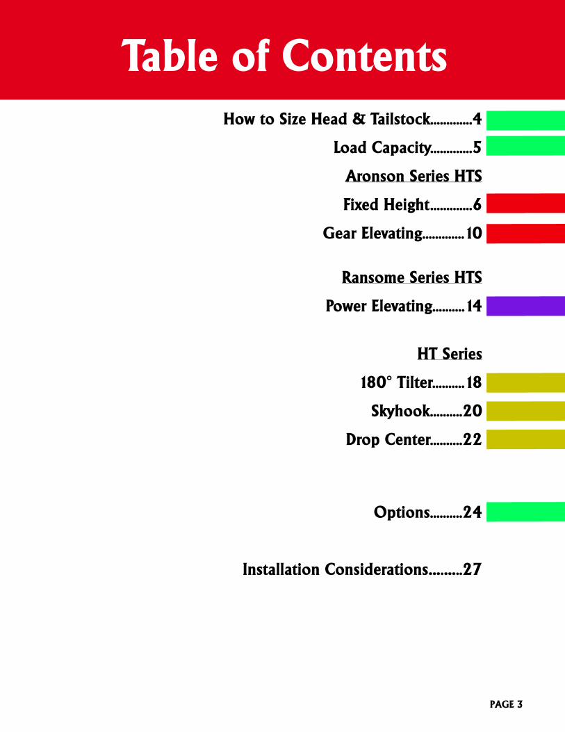
Table of ContentsHow to Size Head & Tailstock.............4
Load Capacity.............5
Aronson Series HTS
Fixed Height.............6
Gear Elevating.............10
Ransome Series HTS
Power Elevating..........14
HT Series
180° Tilter..........18
Skyhook..........20
Drop Center..........22
Options..........24
Installation Considerations….…..27
PAGE 3
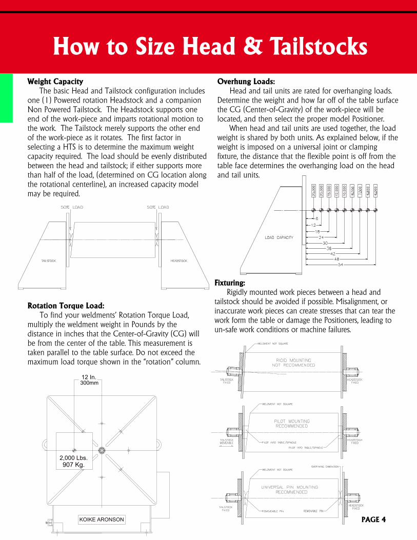
How to Size Head & TailstocksWeight Capacity The basic Head and Tailstock configuration includesone (1) Powered rotation Headstock and a companionNon Powered Tailstock. The Headstock supports oneend of the work-piece and imparts rotational motion tothe work. The Tailstock merely supports the other endof the work-piece as it rotates. The first factor inselecting a HTS is to determine the maximum weightcapacity required. The load should be evenly distributedbetween the head and tailstock; if either supports morethan half of the load, (determined on CG location alongthe rotational centerline), an increased capacity modelmay be required.
Fixturing:Rigidly mounted work pieces between a head and
tailstock should be avoided if possible. Misalignment, orinaccurate work pieces can create stresses that can tear thework form the table or damage the Positioners, leading toun-safe work conditions or machine failures.
KOIKE ARONSON
12 In.300mm
2,000 Lbs.907 Kg.
Rotation Torque Load:To find your weldments’ Rotation Torque Load,
multiply the weldment weight in Pounds by thedistance in inches that the Center-of-Gravity (CG) willbe from the center of the table. This measurement istaken parallel to the table surface. Do not exceed themaximum load torque shown in the “rotation” column.
Overhung Loads:Head and tail units are rated for overhanging loads.
Determine the weight and how far off of the table surfacethe CG (Center-of-Gravity) of the work-piece will belocated, and then select the proper model Positioner.
When head and tail units are used together, the loadweight is shared by both units. As explained below, if theweight is imposed on a universal joint or clampingfixture, the distance that the flexible point is off from thetable face determines the overhanging load on the headand tail units.
PAGE 4
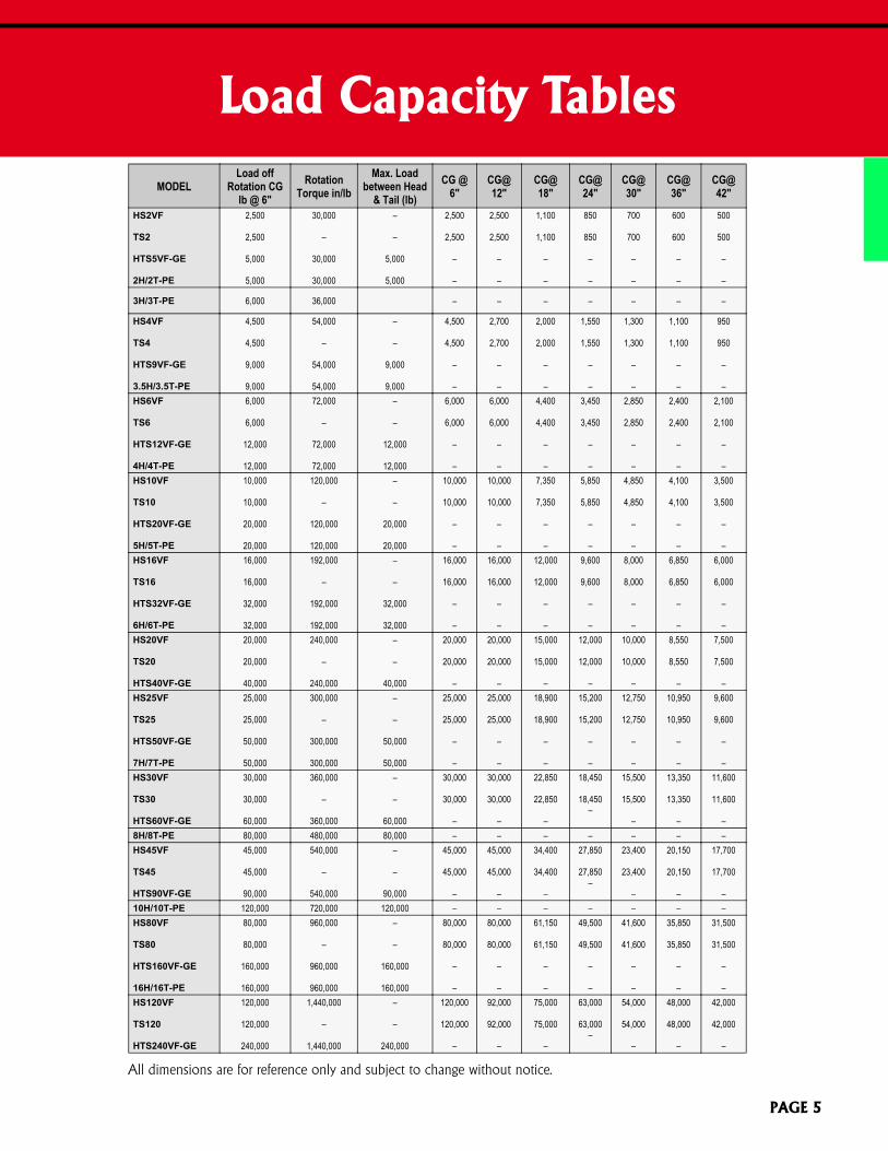
Load Capacity Tables
MODELLoad off
Rotation CGlb @ 6"
RotationTorque in/lb
Max. Loadbetween Head
& Tail (lb)CG @
6"CG@12"
CG@18"
CG@24"
CG@30"
CG@36"
CG@42"
HS2VF
TS2
HTS5VF-GE
2H/2T-PE
2,500
2,500
5,000
5,000
30,000
–
30,000
30,000
–
–
5,000
5,000
2,500
2,500
–
–
2,500
2,500
–
–
1,100
1,100
–
–
850
850
–
–
700
700
–
–
600
600
–
–
500
500
–
–
3H/3T-PE 6,000 36,000 – – – – – – –
HS4VF
TS4
HTS9VF-GE
3.5H/3.5T-PE
4,500
4,500
9,000
9,000
54,000
–
54,000
54,000
–
–
9,000
9,000
4,500
4,500
–
–
2,700
2,700
–
–
2,000
2,000
–
–
1,550
1,550
–
–
1,300
1,300
–
–
1,100
1,100
–
–
950
950
–
–HS6VF
TS6
HTS12VF-GE
4H/4T-PE
6,000
6,000
12,000
12,000
72,000
–
72,000
72,000
–
–
12,000
12,000
6,000
6,000
–
–
6,000
6,000
–
–
4,400
4,400
–
–
3,450
3,450
–
–
2,850
2,850
–
–
2,400
2,400
–
–
2,100
2,100
–
–HS10VF
TS10
HTS20VF-GE
5H/5T-PE
10,000
10,000
20,000
20,000
120,000
–
120,000
120,000
–
–
20,000
20,000
10,000
10,000
–
–
10,000
10,000
–
–
7,350
7,350
–
–
5,850
5,850
–
–
4,850
4,850
–
–
4,100
4,100
–
–
3,500
3,500
–
–HS16VF
TS16
HTS32VF-GE
6H/6T-PE
16,000
16,000
32,000
32,000
192,000
–
192,000
192,000
–
–
32,000
32,000
16,000
16,000
–
–
16,000
16,000
–
–
12,000
12,000
–
–
9,600
9,600
–
–
8,000
8,000
–
–
6,850
6,850
–
–
6,000
6,000
–
–HS20VF
TS20
HTS40VF-GE
20,000
20,000
40,000
240,000
–
240,000
–
–
40,000
20,000
20,000
–
20,000
20,000
–
15,000
15,000
–
12,000
12,000
–
10,000
10,000
–
8,550
8,550
–
7,500
7,500
–HS25VF
TS25
HTS50VF-GE
7H/7T-PE
25,000
25,000
50,000
50,000
300,000
–
300,000
300,000
–
–
50,000
50,000
25,000
25,000
–
–
25,000
25,000
–
–
18,900
18,900
–
–
15,200
15,200
–
–
12,750
12,750
–
–
10,950
10,950
–
–
9,600
9,600
–
–HS30VF
TS30
HTS60VF-GE
30,000
30,000
60,000
360,000
–
360,000
–
–
60,000
30,000
30,000
–
30,000
30,000
–
22,850
22,850
–
18,450
18,450–
15,500
15,500
–
13,350
13,350
–
11,600
11,600
–8H/8T-PE 80,000 480,000 80,000 – – – – – – –HS45VF
TS45
HTS90VF-GE
45,000
45,000
90,000
540,000
–
540,000
–
–
90,000
45,000
45,000
–
45,000
45,000
–
34,400
34,400
–
27,850
27,850–
23,400
23,400
–
20,150
20,150
–
17,700
17,700
–10H/10T-PE 120,000 720,000 120,000 – – – – – – –HS80VF
TS80
HTS160VF-GE
16H/16T-PE
80,000
80,000
160,000
160,000
960,000
–
960,000
960,000
–
–
160,000
160,000
80,000
80,000
–
–
80,000
80,000
–
–
61,150
61,150
–
–
49,500
49,500
–
–
41,600
41,600
–
–
35,850
35,850
–
–
31,500
31,500
–
–HS120VF
TS120
HTS240VF-GE
120,000
120,000
240,000
1,440,000
–
1,440,000
–
–
240,000
120,000
120,000
–
92,000
92,000
–
75,000
75,000
–
63,000
63,000–
54,000
54,000
–
48,000
48,000
–
42,000
42,000
–
All dimensions are for reference only and subject to change without notice.
PAGE 5
KOIKE ARONSON, INC. / RANSOME
ARONSONSeries
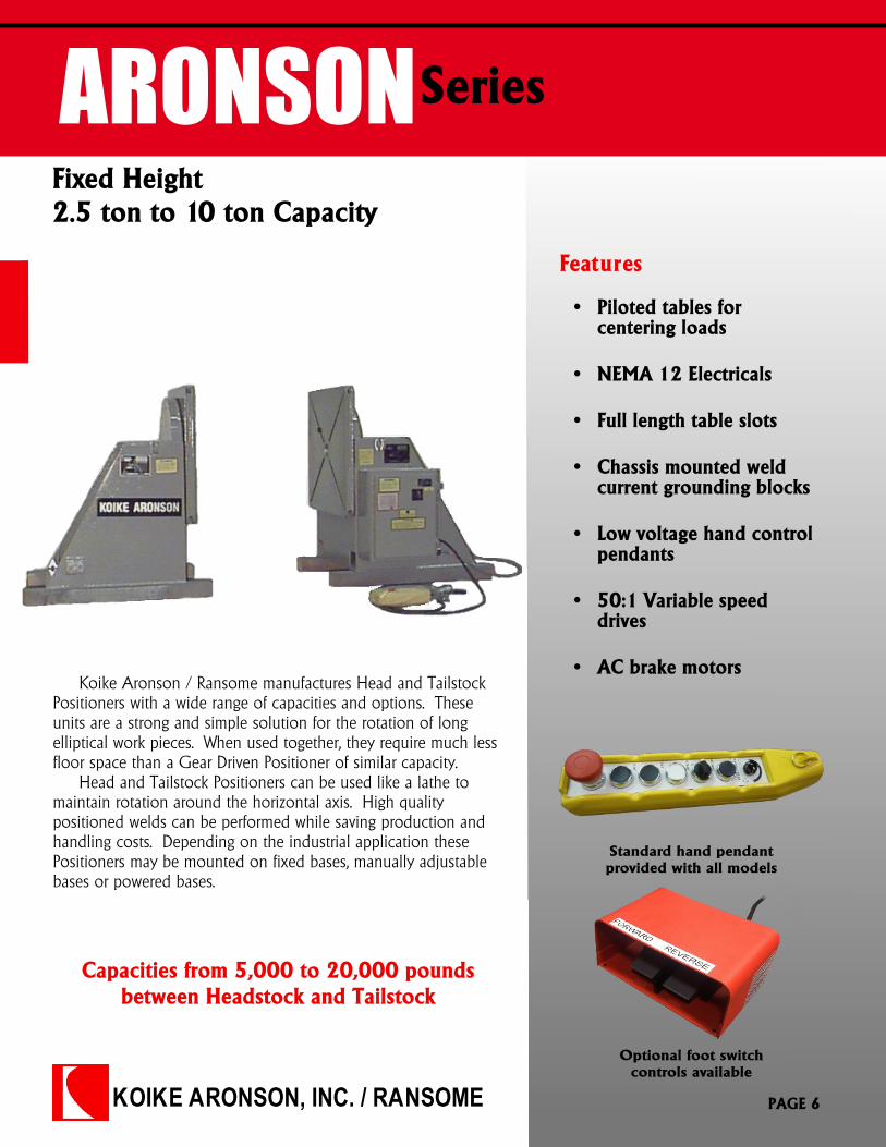
Fixed Height2.5 ton to 10 ton Capacity
Features
Capacities from 5,000 to 20,000 poundsbetween Headstock and Tailstock
Koike Aronson / Ransome manufactures Head and TailstockPositioners with a wide range of capacities and options. Theseunits are a strong and simple solution for the rotation of longelliptical work pieces. When used together, they require much lessfloor space than a Gear Driven Positioner of similar capacity.
Head and Tailstock Positioners can be used like a lathe tomaintain rotation around the horizontal axis. High qualitypositioned welds can be performed while saving production andhandling costs. Depending on the industrial application thesePositioners may be mounted on fixed bases, manually adjustablebases or powered bases.
� Piloted tables forcentering loads
� NEMA 12 Electricals
� Full length table slots
� Chassis mounted weldcurrent grounding blocks
� Low voltage hand controlpendants
� 50:1 Variable speeddrives
� AC brake motors
Standard hand pendantprovided with all models
Optional foot switchcontrols available
PAGE 6
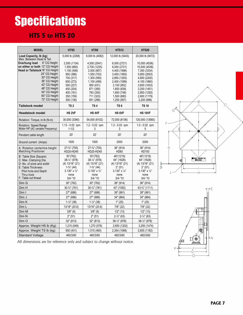
MODEL HTS5 HTS9 HTS12 HTS20
Load Capacity, lb (kg)Max. Between Head & Tail 6” CG Height 12” CG Height 18” CG Height 24” CG Height 30” CG Height 36” CG Height 42” CG Height 48” CG Height 54” CG Height 60” CG Height 72” CG Height
5,000 lb (2268)
2,500 (1134)1,500 (680)1,100 (499)850 (386)700 (317)600 (272)500 (227)450 (204)400 (181)350 (159)300 (136)
9,000 lb (4082)
4,500 (2041)2,700 (1225)2,000 (907)1,550 (703)1,300 (590)1,100 (499)950 (431)871 (395)783 (355)711 (323)651 (296)
12,000 lb (5443)
6,000 (2721)6,000 (2721)4,400 (1996)3,450 (1565)2,850 (1293)2,400 (1089)2,100 (952)1,850 (839)1,650 (748)1,500 (680)1,250 (567)
20,000 lb (9072)
10,000 (4536)10,000 (4536)7,350 (3334)5,850 (2653)4,850 (2200)4,100 (1860)3,600 (1633)3,200 (1451)2,850 (1293)2,600 (1179)2,200 (998)
Tailstock model TS 2 TS 4 TS 6 TS 10
Headstock model HS 2VF HS 4VF HS 6VF HS 10VF
Rotation: Torque, in-lb (N.m) 30,000 (3390) 54,000 (6102) 72,000 (8136) 120,000 (13560)
Rotation: Speed RangeMotor HP (AC variable Frequency)
1.13 - 0.02 rpm1-1/2
1.2 - 0.02 rpm3
1.3 - 0.03 rpm3
1.0 - 0.02 rpm5
Pendant cable length 20' 20' 20' 20'
Ground current (Amps) 1500 1500 2000 2000
A: Rotation centerline heightMatching Positioner
27-¾” (705)HD25-HD45
27-¾” (705)HD25-HD45
36” (914)HD60
36” (914)HD100
B: Table Size (Square)C: Max. Clamping Dia.D: No. of slots and widthE: Table Thickness
Pilot hole and DepthThru-hole
F: Table nut thread
30”(762)38-½” (978)
(4) 13/16” (21)1-¾” (44)
3.130” x ½”none
3/4-”10
30”(762)38-½” (978)
(4) 13/16” (21)1-¾” (44)
3.130” x ½”none
3/4-”10
48”(1219)64” (1626)
(4) 13/16” (21)2” (51)
3.130” x ½”none
3/4-”10
48”(1219)64” (1626)
(4) 13/16” (21)2” (51)
3.130” x ½”none
3/4-”10Dim G 30" (762) 30" (762) 36" (914) 36" (914)Dim H 30-¾" (781) 30-¾" (781) 43" (1092) 43-¾" (1111)Dim I 27" (686) 27" (686) 39" (991) 39" (991)Dim J 27" (686) 27" (686) 34" (864) 34" (864)Dim K 1-½" (38) 1-½" (38) 1" (25) 1" (25)Dim L 13/16" (20.6) 13/16" (20.6) 7/8" (22) 7/8" (22)Dim M 3/8" (9) 3/8" (9) 1/2" (13) 1/2" (13)Dim N 2" (51) 2" (51) 2-½" (63) 2-½" (63)Dim O 32" (813) 32" (813) 38-½" (978) 38-½" (978)Approx. Weight HS lb (Kg) 1,210 (549) 1,270 (576) 2,650 (1202) 3,250 (1474)Approx. Weight TS lb (kg) 950 (431) 1,015 (460) 2,354 (1068) 2,605 (1182)Standard Voltage 460/3/60 460/3/60 460/3/60 460/3/60
SpecificationsHTS 5 to HTS 20
PAGE 7
All dimensions are for reference only and subject to change without notice.
Overhung loadon either or bothHead or Tailstock
KOIKE ARONSON, INC. / RANSOME
ARONSON Series
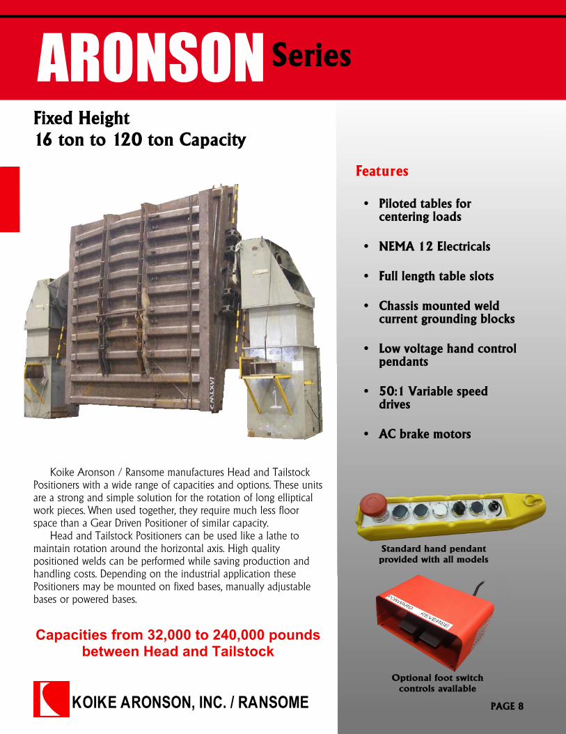
Fixed Height16 ton to 120 ton Capacity
Features
Capacities from 32,000 to 240,000 poundsbetween Head and Tailstock
Standard hand pendantprovided with all models
Optional foot switchcontrols available
Koike Aronson / Ransome manufactures Head and TailstockPositioners with a wide range of capacities and options. These unitsare a strong and simple solution for the rotation of long ellipticalwork pieces. When used together, they require much less floorspace than a Gear Driven Positioner of similar capacity.
Head and Tailstock Positioners can be used like a lathe tomaintain rotation around the horizontal axis. High qualitypositioned welds can be performed while saving production andhandling costs. Depending on the industrial application thesePositioners may be mounted on fixed bases, manually adjustablebases or powered bases.
� Piloted tables forcentering loads
� NEMA 12 Electricals
� Full length table slots
� Chassis mounted weldcurrent grounding blocks
� Low voltage hand controlpendants
� 50:1 Variable speeddrives
� AC brake motors
PAGE 8
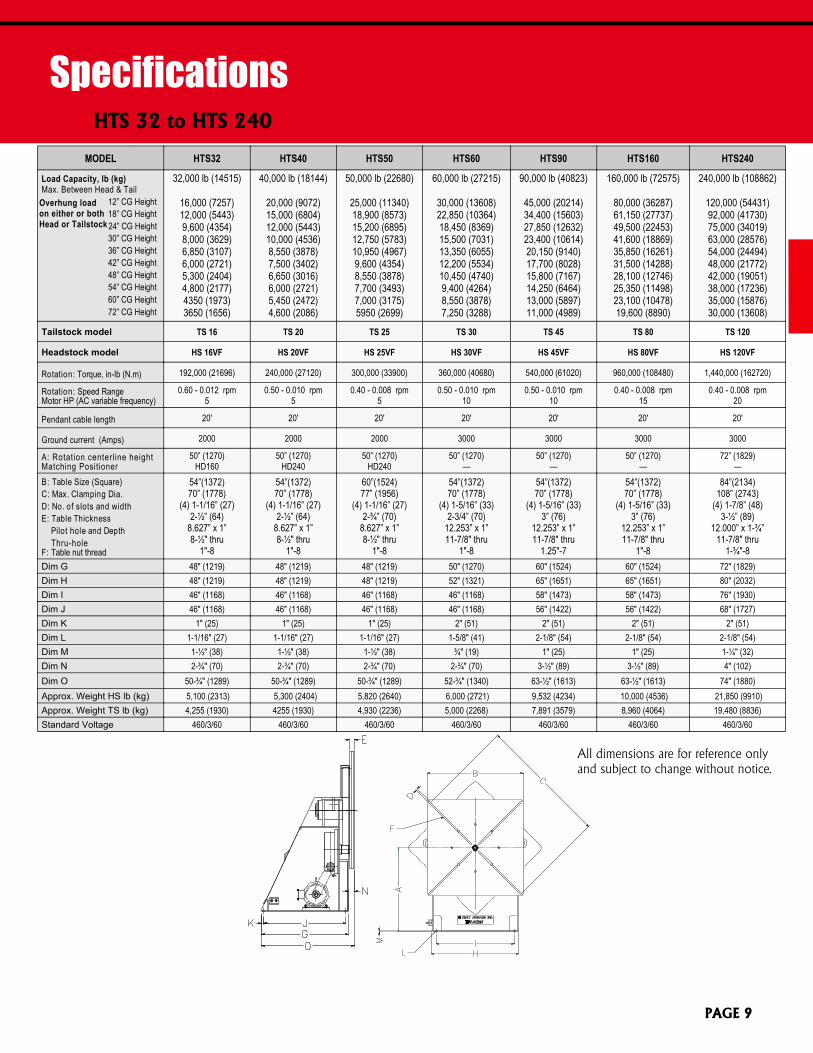
SpecificationsHTS 32 to HTS 240
All dimensions are for reference onlyand subject to change without notice.
MODEL HTS32 HTS40 HTS50 HTS60 HTS90 HTS160 HTS240
Load Capacity, lb (kg)Max. Between Head & Tail 12” CG Height 18” CG Height 24” CG Height 30” CG Height 36” CG Height 42” CG Height 48” CG Height 54” CG Height 60” CG Height 72” CG Height
32,000 lb (14515)
16,000 (7257)12,000 (5443)9,600 (4354)8,000 (3629)6,850 (3107)6,000 (2721)5,300 (2404)4,800 (2177)4350 (1973)3650 (1656)
40,000 lb (18144)
20,000 (9072)15,000 (6804)12,000 (5443)10,000 (4536)8,550 (3878)7,500 (3402)6,650 (3016)6,000 (2721)5,450 (2472)4,600 (2086)
50,000 lb (22680)
25,000 (11340)18,900 (8573)15,200 (6895)12,750 (5783)10,950 (4967)9,600 (4354)8,550 (3878)7,700 (3493)7,000 (3175)5950 (2699)
60,000 lb (27215)
30,000 (13608)22,850 (10364)18,450 (8369)15,500 (7031)13,350 (6055)12,200 (5534)10,450 (4740)9,400 (4264)8,550 (3878)7,250 (3288)
90,000 lb (40823)
45,000 (20214)34,400 (15603)27,850 (12632)23,400 (10614)20,150 (9140)17,700 (8028)15,800 (7167)14,250 (6464)13,000 (5897)11,000 (4989)
160,000 lb (72575)
80,000 (36287)61,150 (27737)49,500 (22453)41,600 (18869)35,850 (16261)31,500 (14288)28,100 (12746)25,350 (11498)23,100 (10478)19,600 (8890)
240,000 lb (108862)
120,000 (54431)92,000 (41730)75,000 (34019)63,000 (28576)54,000 (24494)48,000 (21772)42,000 (19051)38,000 (17236)35,000 (15876)30,000 (13608)
Tailstock model TS 16 TS 20 TS 25 TS 30 TS 45 TS 80 TS 120
Headstock model HS 16VF HS 20VF HS 25VF HS 30VF HS 45VF HS 80VF HS 120VF
Rotation: Torque, in-lb (N.m) 192,000 (21696) 240,000 (27120) 300,000 (33900) 360,000 (40680) 540,000 (61020) 960,000 (108480) 1,440,000 (162720)
Rotation: Speed RangeMotor HP (AC variable frequency)
0.60 - 0.012 rpm5
0.50 - 0.010 rpm5
0.40 - 0.008 rpm5
0.50 - 0.010 rpm10
0.50 - 0.010 rpm10
0.40 - 0.008 rpm15
0.40 - 0.008 rpm20
Pendant cable length 20' 20' 20' 20' 20' 20' 20'
Ground current (Amps) 2000 2000 2000 3000 3000 3000 3000
A: Rotation centerline heightMatching Positioner
50” (1270)HD160
50” (1270)HD240
50” (1270)HD240
50” (1270)—
50” (1270)—
50” (1270)—
72” (1829)—
B: Table Size (Square)C: Max. Clamping Dia.D: No. of slots and widthE: Table Thickness
Pilot hole and DepthThru-hole
F: Table nut thread
54”(1372)70” (1778)
(4) 1-1/16” (27)2-½” (64)
8.627” x 1”8-½" thru
1"-8
54”(1372)70” (1778)
(4) 1-1/16” (27)2-½” (64)
8.627” x 1”8-½" thru
1"-8
60”(1524)77” (1956)
(4) 1-1/16” (27)2-¾” (70)
8.627” x 1”8-½" thru
1"-8
54”(1372)70” (1778)
(4) 1-5/16” (33)2-3/4” (70)
12.253” x 1”11-7/8" thru
1"-8
54”(1372)70” (1778)
(4) 1-5/16” (33)3” (76)
12.253” x 1”11-7/8" thru
1.25"-7
54”(1372)70” (1778)
(4) 1-5/16” (33)3” (76)
12.253” x 1”11-7/8" thru
1"-8
84”(2134)108” (2743)
(4) 1-7/8” (48)3-½” (89)
12.000” x 1-¾”11-7/8" thru
1-¾"-8Dim G 48" (1219) 48" (1219) 48" (1219) 50" (1270) 60" (1524) 60" (1524) 72" (1829)Dim H 48" (1219) 48" (1219) 48" (1219) 52" (1321) 65" (1651) 65" (1651) 80" (2032)Dim I 46" (1168) 46" (1168) 46" (1168) 46" (1168) 58" (1473) 58" (1473) 76" (1930)Dim J 46" (1168) 46" (1168) 46" (1168) 46" (1168) 56" (1422) 56" (1422) 68" (1727)Dim K 1" (25) 1" (25) 1" (25) 2" (51) 2" (51) 2" (51) 2" (51)Dim L 1-1/16" (27) 1-1/16" (27) 1-1/16" (27) 1-5/8" (41) 2-1/8" (54) 2-1/8" (54) 2-1/8" (54)Dim M 1-½" (38) 1-½" (38) 1-½" (38) ¾" (19) 1" (25) 1" (25) 1-¼" (32)Dim N 2-¾" (70) 2-¾" (70) 2-¾" (70) 2-¾" (70) 3-½" (89) 3-½" (89) 4" (102)Dim O 50-¾" (1289) 50-¾" (1289) 50-¾" (1289) 52-¾" (1340) 63-½" (1613) 63-½" (1613) 74" (1880)Approx. Weight HS lb (kg) 5,100 (2313) 5,300 (2404) 5,820 (2640) 6,000 (2721) 9,532 (4234) 10,000 (4536) 21,850 (9910)Approx. Weight TS lb (kg) 4,255 (1930) 4255 (1930) 4,930 (2236) 5,000 (2268) 7,891 (3579) 8,960 (4064) 19,480 (8836)Standard Voltage 460/3/60 460/3/60 460/3/60 460/3/60 460/3/60 460/3/60 460/3/60
Overhung loadon either or bothHead or Tailstock
PAGE 9
KOIKE ARONSON, INC. / RANSOME
ARONSON Series
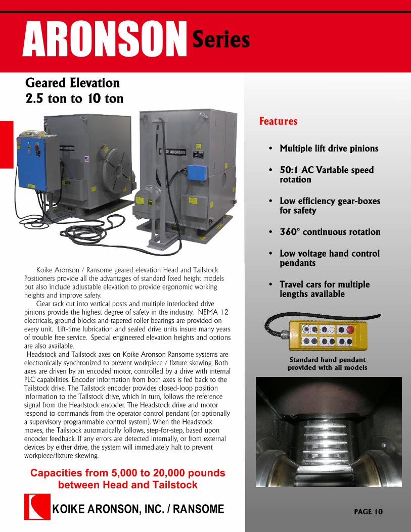
Geared Elevation2.5 ton to 10 ton
Features
Capacities from 5,000 to 20,000 poundsbetween Head and Tailstock
Standard hand pendantprovided with all models
Koike Aronson / Ransome geared elevation Head and TailstockPositioners provide all the advantages of standard fixed height modelsbut also include adjustable elevation to provide ergonomic workingheights and improve safety.
Gear rack cut into vertical posts and multiple interlocked drivepinions provide the highest degree of safety in the industry. NEMA 12electricals, ground blocks and tapered roller bearings are provided onevery unit. Lift-time lubrication and sealed drive units insure many yearsof trouble free service. Special engineered elevation heights and optionsare also available.Headstock and Tailstock axes on Koike Aronson Ransome systems are
electronically synchronized to prevent workpiece / fixture skewing. Bothaxes are driven by an encoded motor, controlled by a drive with internalPLC capabilities. Encoder information from both axes is fed back to theTailstock drive. The Tailstock encoder provides closed-loop positioninformation to the Tailstock drive, which in turn, follows the referencesignal from the Headstock encoder. The Headstock drive and motorrespond to commands from the operator control pendant (or optionallya supervisory programmable control system). When the Headstockmoves, the Tailstock automatically follows, step-for-step, based uponencoder feedback. If any errors are detected internally, or from externaldevices by either drive, the system will immediately halt to preventworkpiece/fixture skewing.
� Multiple lift drive pinions
� 50:1 AC Variable speedrotation
� Low efficiency gear-boxesfor safety
� 360° continuous rotation
� Low voltage hand controlpendants
� Travel cars for multiplelengths available
PAGE 10
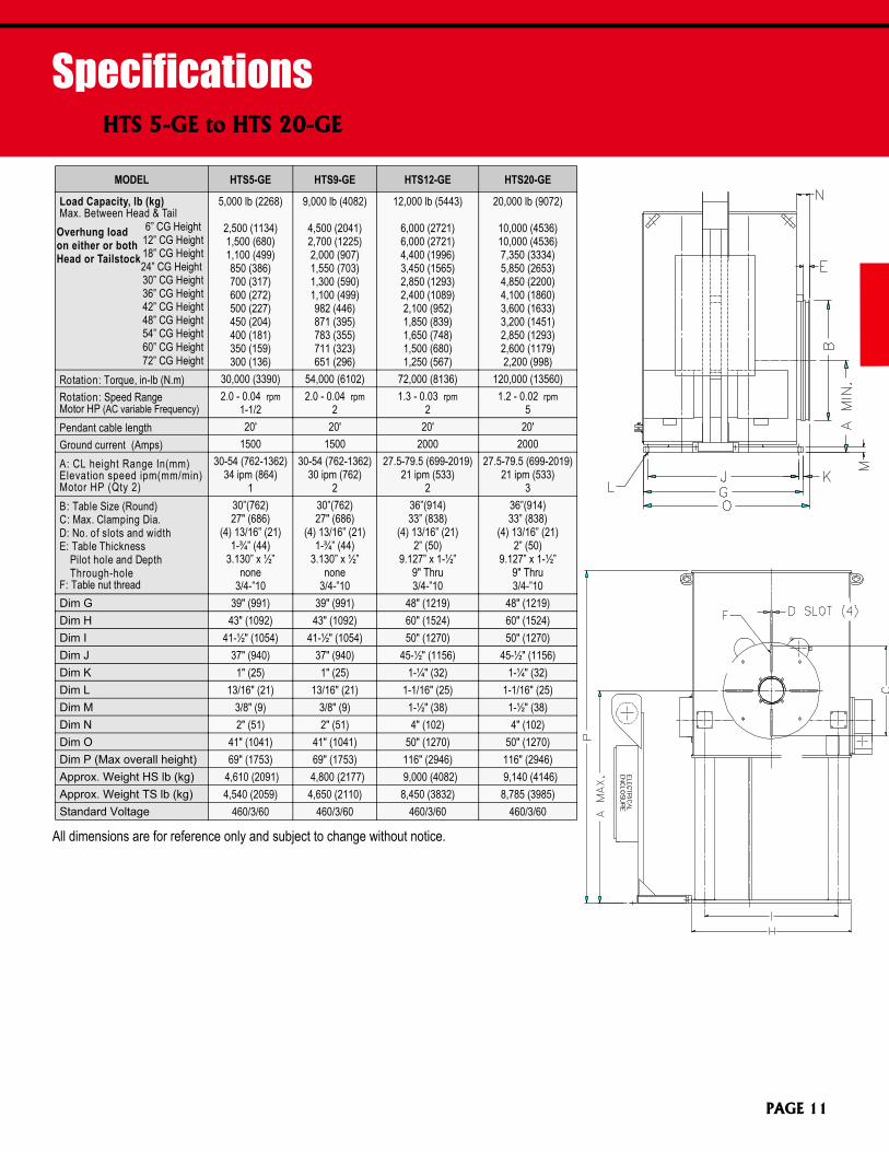
SpecificationsHTS 5-GE to HTS 20-GE
All dimensions are for reference only and subject to change without notice.
MODEL HTS5-GE HTS9-GE HTS12-GE HTS20-GE
Load Capacity, lb (kg)Max. Between Head & Tail 6” CG Height 12” CG Height 18” CG Height 24” CG Height 30” CG Height 36” CG Height 42” CG Height 48” CG Height 54” CG Height 60” CG Height 72” CG Height
5,000 lb (2268)
2,500 (1134)1,500 (680)1,100 (499)850 (386)700 (317)600 (272)500 (227)450 (204)400 (181)350 (159)300 (136)
9,000 lb (4082)
4,500 (2041)2,700 (1225)2,000 (907)1,550 (703)1,300 (590)1,100 (499)982 (446)871 (395)783 (355)711 (323)651 (296)
12,000 lb (5443)
6,000 (2721)6,000 (2721)4,400 (1996)3,450 (1565)2,850 (1293)2,400 (1089)2,100 (952)1,850 (839)1,650 (748)1,500 (680)1,250 (567)
20,000 lb (9072)
10,000 (4536)10,000 (4536)7,350 (3334)5,850 (2653)4,850 (2200)4,100 (1860)3,600 (1633)3,200 (1451)2,850 (1293)2,600 (1179)2,200 (998)
Rotation: Torque, in-lb (N.m) 30,000 (3390) 54,000 (6102) 72,000 (8136) 120,000 (13560)Rotation: Speed RangeMotor HP (AC variable Frequency)
2.0 - 0.04 rpm1-1/2
2.0 - 0.04 rpm2
1.3 - 0.03 rpm2
1.2 - 0.02 rpm5
Pendant cable length 20' 20' 20' 20'Ground current (Amps) 1500 1500 2000 2000A: CL height Range In(mm)Elevation speed ipm(mm/min)Motor HP (Qty 2)
30-54 (762-1362)34 ipm (864)
1
30-54 (762-1362)30 ipm (762)
2
27.5-79.5 (699-2019)21 ipm (533)
2
27.5-79.5 (699-2019)21 ipm (533)
3B: Table Size (Round)C: Max. Clamping Dia.D: No. of slots and widthE: Table Thickness
Pilot hole and DepthThrough-hole
F: Table nut thread
30”(762)27" (686)
(4) 13/16” (21)1-¾” (44)
3.130” x ½”none
3/4-”10
30”(762)27" (686)
(4) 13/16” (21)1-¾” (44)
3.130” x ½”none
3/4-”10
36”(914)33” (838)
(4) 13/16” (21)2” (50)
9.127” x 1-½”9" Thru3/4-”10
36”(914)33” (838)
(4) 13/16” (21)2” (50)
9.127” x 1-½”9" Thru3/4-”10
Dim G 39" (991) 39" (991) 48" (1219) 48" (1219)Dim H 43" (1092) 43" (1092) 60" (1524) 60" (1524)Dim I 41-½" (1054) 41-½" (1054) 50" (1270) 50" (1270)Dim J 37" (940) 37" (940) 45-½" (1156) 45-½" (1156)Dim K 1" (25) 1" (25) 1-¼" (32) 1-¼" (32)Dim L 13/16" (21) 13/16" (21) 1-1/16" (25) 1-1/16" (25)Dim M 3/8" (9) 3/8" (9) 1-½" (38) 1-½" (38)Dim N 2" (51) 2" (51) 4" (102) 4" (102)Dim O 41" (1041) 41" (1041) 50" (1270) 50" (1270)Dim P (Max overall height) 69" (1753) 69" (1753) 116" (2946) 116" (2946)Approx. Weight HS lb (kg) 4,610 (2091) 4,800 (2177) 9,000 (4082) 9,140 (4146)Approx. Weight TS lb (kg) 4,540 (2059) 4,650 (2110) 8,450 (3832) 8,785 (3985)Standard Voltage 460/3/60 460/3/60 460/3/60 460/3/60
Overhung loadon either or bothHead or Tailstock
PAGE 11
KOIKE ARONSON, INC. / RANSOME
ARONSONSeries
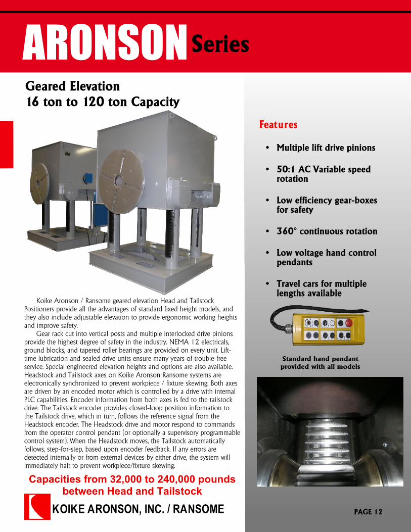
Geared Elevation16 ton to 120 ton Capacity
Features
Capacities from 32,000 to 240,000 poundsbetween Head and Tailstock
Koike Aronson / Ransome geared elevation Head and TailstockPositioners provide all the advantages of standard fixed height models, andthey also include adjustable elevation to provide ergonomic working heightsand improve safety.
Gear rack cut into vertical posts and multiple interlocked drive pinionsprovide the highest degree of safety in the industry. NEMA 12 electricals,ground blocks, and tapered roller bearings are provided on every unit. Lift-time lubrication and sealed drive units ensure many years of trouble-freeservice. Special engineered elevation heights and options are also available.Headstock and Tailstock axes on Koike Aronson Ransome systems areelectronically synchronized to prevent workpiece / fixture skewing. Both axesare driven by an encoded motor which is controlled by a drive with internalPLC capabilities. Encoder information from both axes is fed to the tailstockdrive. The Tailstock encoder provides closed-loop position information tothe Tailstock drive, which in turn, follows the reference signal from theHeadstock encoder. The Headstock drive and motor respond to commandsfrom the operator control pendant (or optionally a supervisory programmablecontrol system). When the Headstock moves, the Tailstock automaticallyfollows, step-for-step, based upon encoder feedback. If any errors aredetected internally or from external devices by either drive, the system willimmediately halt to prevent workpiece/fixture skewing.
� Multiple lift drive pinions
� 50:1 AC Variable speedrotation
� Low efficiency gear-boxesfor safety
� 360° continuous rotation
� Low voltage hand controlpendants
� Travel cars for multiplelengths available
PAGE 12
Standard hand pendantprovided with all models
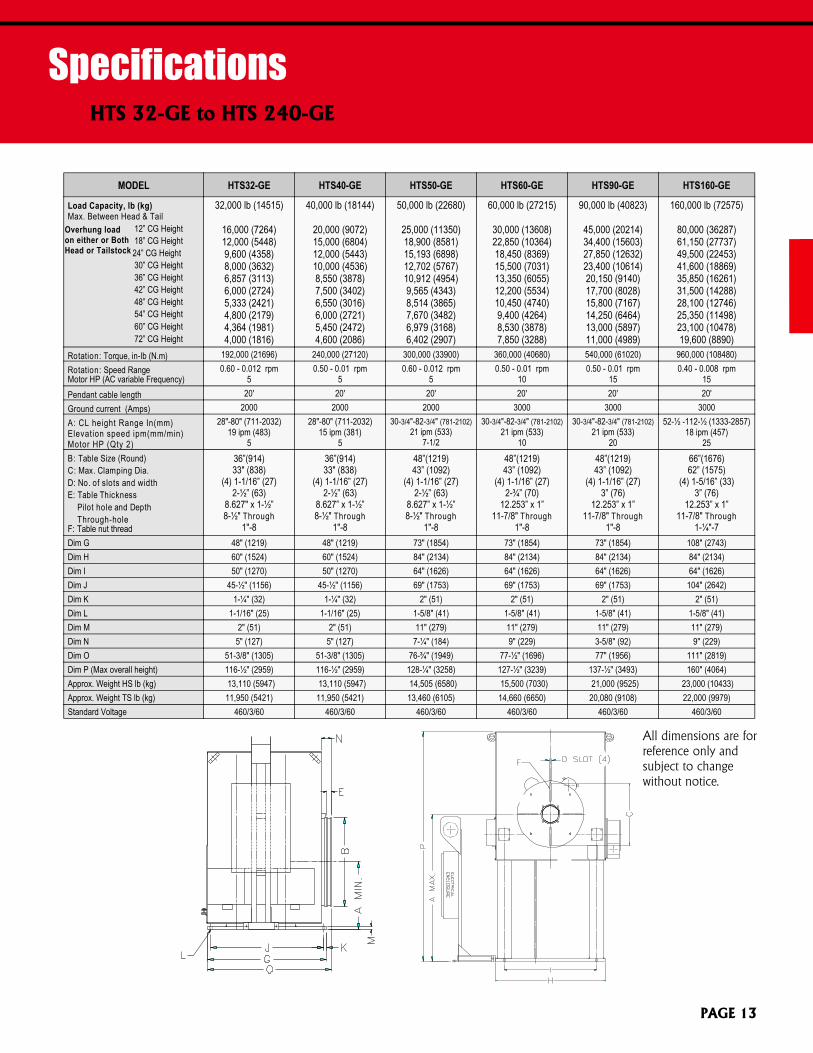
SpecificationsHTS 32-GE to HTS 240-GE
MODEL HTS32-GE HTS40-GE HTS50-GE HTS60-GE HTS90-GE HTS160-GE
Load Capacity, lb (kg)Max. Between Head & Tail 12” CG Height 18” CG Height 24” CG Height 30” CG Height 36” CG Height 42” CG Height 48” CG Height 54” CG Height 60” CG Height 72” CG Height
32,000 lb (14515)
16,000 (7264)12,000 (5448)9,600 (4358)8,000 (3632)6,857 (3113)6,000 (2724)5,333 (2421)4,800 (2179)4,364 (1981)4,000 (1816)
40,000 lb (18144)
20,000 (9072)15,000 (6804)12,000 (5443)10,000 (4536)8,550 (3878)7,500 (3402)6,550 (3016)6,000 (2721)5,450 (2472)4,600 (2086)
50,000 lb (22680)
25,000 (11350)18,900 (8581)15,193 (6898)12,702 (5767)10,912 (4954)9,565 (4343)8,514 (3865)7,670 (3482)6,979 (3168)6,402 (2907)
60,000 lb (27215)
30,000 (13608)22,850 (10364)18,450 (8369)15,500 (7031)13,350 (6055)12,200 (5534)10,450 (4740)9,400 (4264)8,530 (3878)7,850 (3288)
90,000 lb (40823)
45,000 (20214)34,400 (15603)27,850 (12632)23,400 (10614)20,150 (9140)17,700 (8028)15,800 (7167)14,250 (6464)13,000 (5897)11,000 (4989)
160,000 lb (72575)
80,000 (36287)61,150 (27737)49,500 (22453)41,600 (18869)35,850 (16261)31,500 (14288)28,100 (12746)25,350 (11498)23,100 (10478)19,600 (8890)
Rotation: Torque, in-lb (N.m) 192,000 (21696) 240,000 (27120) 300,000 (33900) 360,000 (40680) 540,000 (61020) 960,000 (108480)Rotation: Speed RangeMotor HP (AC variable Frequency)
0.60 - 0.012 rpm5
0.50 - 0.01 rpm5
0.60 - 0.012 rpm5
0.50 - 0.01 rpm10
0.50 - 0.01 rpm15
0.40 - 0.008 rpm15
Pendant cable length 20' 20' 20' 20' 20' 20'Ground current (Amps) 2000 2000 2000 3000 3000 3000A: CL height Range In(mm)Elevation speed ipm(mm/min)Motor HP (Qty 2)
28"-80" (711-2032)19 ipm (483)
5
28"-80" (711-2032)15 ipm (381)
5
30-3/4"-82-3/4" (781-2102)21 ipm (533)
7-1/2
30-3/4"-82-3/4" (781-2102)21 ipm (533)
10
30-3/4"-82-3/4" (781-2102)21 ipm (533)
20
52-½ -112-½ (1333-2857)18 ipm (457)
25B: Table Size (Round)C: Max. Clamping Dia.D: No. of slots and widthE: Table Thickness
Pilot hole and DepthThrough-hole
F: Table nut thread
36”(914)33" (838)
(4) 1-1/16” (27)2-½” (63)
8.627" x 1-½”8-½" Through
1"-8
36”(914)33" (838)
(4) 1-1/16” (27)2-½” (63)
8.627” x 1-½”8-½" Through
1"-8
48”(1219)43” (1092)
(4) 1-1/16” (27)2-½” (63)
8.627” x 1-½”8-½" Through
1"-8
48”(1219)43” (1092)
(4) 1-1/16” (27)2-¾” (70)
12.253” x 1”11-7/8" Through
1"-8
48”(1219)43” (1092)
(4) 1-1/16” (27)3” (76)
12.253” x 1”11-7/8" Through
1"-8
66”(1676)62” (1575)
(4) 1-5/16” (33)3” (76)
12.253” x 1”11-7/8" Through
1-¼"-7Dim G 48" (1219) 48" (1219) 73" (1854) 73" (1854) 73" (1854) 108" (2743)Dim H 60" (1524) 60" (1524) 84" (2134) 84" (2134) 84" (2134) 84" (2134)Dim I 50" (1270) 50" (1270) 64" (1626) 64" (1626) 64" (1626) 64" (1626)Dim J 45-½" (1156) 45-½" (1156) 69" (1753) 69" (1753) 69" (1753) 104" (2642)Dim K 1-¼" (32) 1-¼" (32) 2" (51) 2" (51) 2" (51) 2" (51)Dim L 1-1/16" (25) 1-1/16" (25) 1-5/8" (41) 1-5/8" (41) 1-5/8" (41) 1-5/8" (41)Dim M 2" (51) 2" (51) 11" (279) 11" (279) 11" (279) 11" (279)Dim N 5" (127) 5" (127) 7-¼" (184) 9" (229) 3-5/8" (92) 9" (229)Dim O 51-3/8" (1305) 51-3/8" (1305) 76-¾" (1949) 77-½" (1696) 77" (1956) 111" (2819)Dim P (Max overall height) 116-½" (2959) 116-½" (2959) 128-¼" (3258) 127-½" (3239) 137-½" (3493) 160" (4064)Approx. Weight HS lb (kg) 13,110 (5947) 13,110 (5947) 14,505 (6580) 15,500 (7030) 21,000 (9525) 23,000 (10433)Approx. Weight TS lb (kg) 11,950 (5421) 11,950 (5421) 13,460 (6105) 14,660 (6650) 20,080 (9108) 22,000 (9979)Standard Voltage 460/3/60 460/3/60 460/3/60 460/3/60 460/3/60 460/3/60
Overhung loadon either or BothHead or Tailstock
All dimensions are forreference only andsubject to changewithout notice.
PAGE 13

KOIKE ARONSON, INC. / RANSOME
RANSOME Series
Ball Screw Elevation2.5 ton to 10 ton
The Powered Elevation design makes maximum use ofcommercially available components, both in the elevation and rotationsystems. Elevation is by means of commercial ball screw jacks for high dutycycle operation and driven by a worm/wormgear arrangement. Theelevation axis uses two of these screw jacks for redundancy bycoupling them together, and then they are driven by a common motor.Belts, chains, and transfer gears are no longer utilized in the design. Guidance is provided by means of wide, large diameter camfollower bearings on flat guide-ways. Cam follower contact with theguide-ways is adjustable for wear. Guidance is provided on the front,back, and sides of two columns that rigidly support the cantileveredload.
Headstock and Tailstock axes on Koike Aronson Ransomesystems are electronically synchronized to prevent workpiece / fixtureskewing. Both axes are driven by an encoded motor which iscontrolled by a drive with internal PLC capabilities. Encoderinformation from both axes is fed to the Tailstock drive. The Tailstockencoder provides closed-loop position information to the Tailstockdrive, which, in turn, follows the reference signal from the Headstockencoder. The Headstock drive and motor respond to commands fromthe operator control pendant (or optionally a supervisoryprogrammable control system). When the Headstock moves, theTailstock automatically follows, step-for-step, based upon encoderfeedback. If any errors are detected internally or from external devicesby either drive, the system will immediately halt to prevent
Capacities from 5,000 to 20,000 poundsbetween Headstock and Tailstock
Features
� Low efficiency gear-boxesfor safety
� Ball screw jacks for highduty cycles
� Machined tables
� Low voltage hand controlpendants
� 50:1 AC Variable speeddrives
� Boots on elevation jacksprotect screws from debris
Optional foot switchcontrols available
Standard hand pendantprovided with all models
PAGE 14
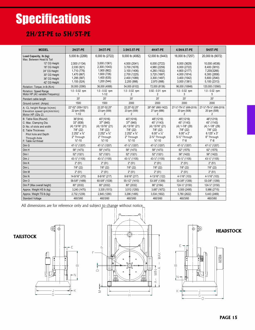
Specifications2H/2T-PE to 5H/5T-PE
All dimensions are for reference only and subject to change without notice.
MODEL 2H/2T-PE 3H/3T-PE 3.5H/3.5T-PE 4H/4T-PE 4.5H/4.5T-PE 5H/5T-PE
Load Capacity, lb (kg)Max. Between Head & Tail 12” CG Height 18” CG Height 24” CG Height 30” CG Height 36” CG Height 42” CG Height
5,000 lb (2268)
2,500 (1134)2,030 (921)1,710 (776)1,470 (667)1,295 (587)1,155 (524)
6,000 lb (2722)
3,000 (1361)2,300 (1043)1,900 (862)1,600 (726)1,400 (635)1,200 (544)
9,000 lb (4082)
4,500 (2041)3,700 (1678)3,100 (1406)2,700 (1225)2,400 (1089)2,200 (998)
12,000 lb (5443)
6,000 (2722)4,980 (2259)4,260 (1932)3,720 (1687)3,300 (1497)2,970 (998)
16,000 lb (7257)
8,000 (3629)6,000 (2722)4,800 (2177)4,000 (1814)3,400 (1542)3,000 (1361)
20,000 lb (9072)
10,000 (4536)8,400 (3810)7,200(3266)6,300 (2858)5,600 (2540)5,100 (2313)
Rotation: Torque, in-lb (N.m) 30,000 (3390) 36,000 (4068) 54,000 (6102) 72,000 (8136) 96,000 (10848) 120,000 (13560)Rotation: Speed RangeMotor HP (AC variable Frequency)
1.0 - 0.02 rpm1
1.0 - 0.02 rpm1-1/2
1.0 - 0.02 rpm2
0.92 - 0.01 rpm2
1.0 - 0.02 rpm3
1.0 - 0.02 rpm5
Pendant cable length 20' 20' 20' 20' 20' 20'Ground current (Amps) 1500 1500 2000 2000 2000 2000A: CL height Range In(mm)Elevation speed ipm(mm/min)Motor HP (Qty 2)
22"-52" (559-1321)22 ipm (559)
1-1/2
22.25"-52.25"23 ipm (559)
2
22.25"-52.25"23 ipm (559)
2
26"-56" (660-1422)27 ipm (686)
2
27-½"-79-½" (699-2019)20 ipm (508)
2
27-½"-79-½" (699-2019)20 ipm (508)
2B: Table Size (Round)C: Max. Clamping Dia.D: No. of slots and widthE: Table Thickness
Pilot hole and DepthThrough-hole
F: Table nut thread
36”(914)33" (838)
(4) 13/16” (21)7/8” (22)
2.252” x ¾”2" Through
¾"-10
40”(1016)37" (940)
(4) 13/16” (21)7/8” (22)
2.252” x ¾”2" Through
¾"-10
40”(1016)37" (940)
(4) 13/16” (21)7/8” (22)
2.252” x ¾”2" Through
¾"-10
48”(1219)45” (1143)
(4) 13/16” (21)7/8” (22)
6.00” x ½”2-¾" Through
¾"-10
48”(1219)45” (1143)
(4) 1-1/8” (29)7/8” (22)6.00” x 2”
5-½" Through1"-8
48”(1219)45” (1143)
(4) 1-1/8” (29)7/8” (22)
6.125” x 3”6" Through
1"-8Dim G 47-½" (1207) 47-½" (1207) 47-½" (1207) 47-½" (1207) 47-½" (1207) 47-½" (1207)Dim H 58" (1473) 58" (1473) 58" (1473) 58" (1473) 62" (1575) 62" (1575)Dim I 52" (1321) 52" (1321) 52" (1321) 52" (1321) 56" (1422) 56" (1422)Dim J 43-½" (1105) 43-½" (1105) 43-½" (1105) 43-½" (1105) 43-½" (1105) 43-½" (1105)Dim K 2" (51) 2" (51) 2" (51) 2" (51) 2" (51) 2" (51)Dim L 7/8" (22) 7/8" (22) 7/8" (22) 7/8" (22) 7/8" (22) 7/8" (22)Dim M 2" (51) 2" (51) 2" (51) 2" (51) 2" (51) 2" (51)Dim N 14-9/16" (370) 8-9/16" (217) 8-9/16" (217) 4-13/16" (122) 4-1/16" (103) 4-1/16" (103)Dim O 58-5/8" (1489) 60-5/8" (1538) 55-1/2" (1410) 53-3/8" (1356) 53-3/8" (1356) 53-3/8" (1356)Dim P (Max overall height) 80" (2032) 80" (2032) 80" (2032) 86" (2184) 124-½" (3150) 124-½" (3150)Approx. Weight HS lb (kg) 3,240 (1470) 3,335 (1513) 3,512 (1293) 3,687 (1672) 5,500 (2495) 5,986 (2715)Approx. Weight TS lb (kg) 2,732 (1239) 2,845 (1290) 3,296 (1495) 3,534 (1602) 5,780 (2622) 5,443 (2469)Standard Voltage 460/3/60 460/3/60 460/3/60 460/3/60 460/3/60 460/3/60
HEADSTOCKTAILSTOCK
PAGE 15
KOIKE ARONSON, INC. / RANSOME
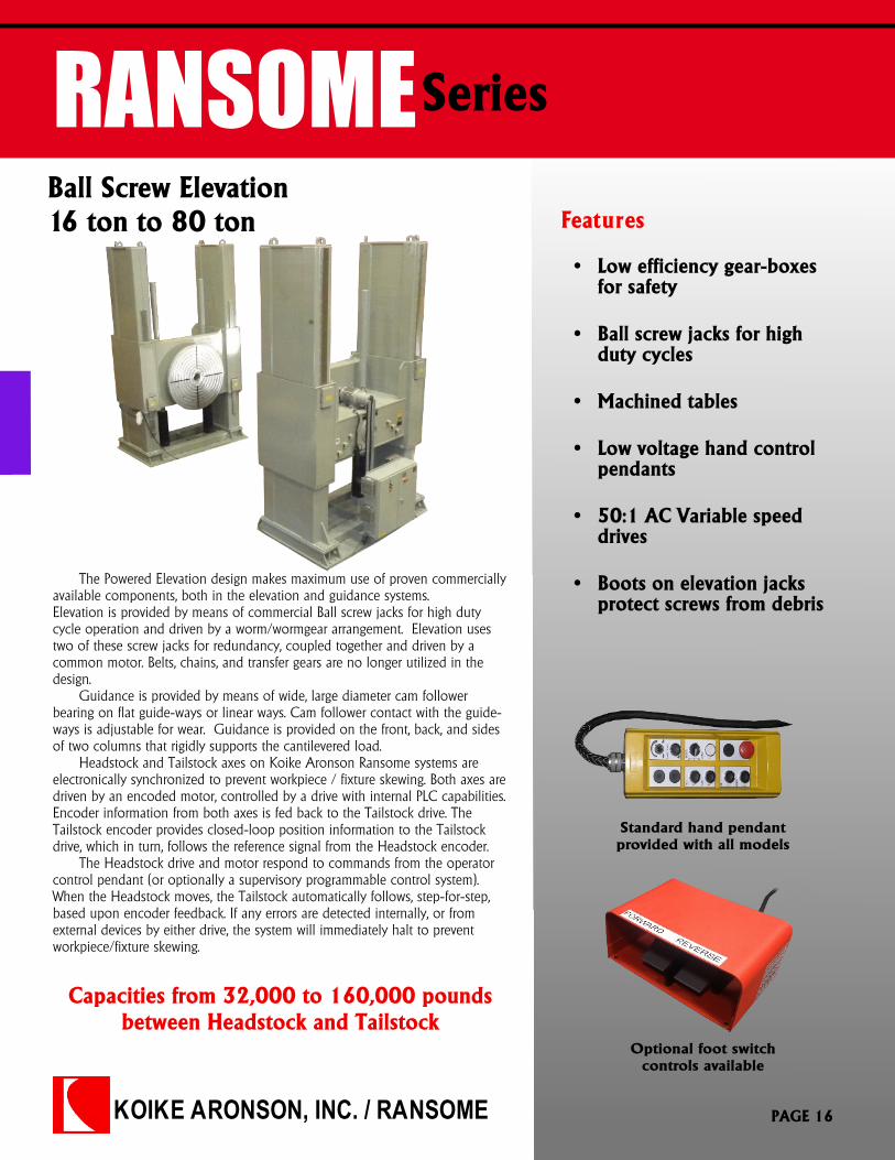
RANSOMEFeatures
Series
The Powered Elevation design makes maximum use of proven commerciallyavailable components, both in the elevation and guidance systems.Elevation is provided by means of commercial Ball screw jacks for high dutycycle operation and driven by a worm/wormgear arrangement. Elevation usestwo of these screw jacks for redundancy, coupled together and driven by acommon motor. Belts, chains, and transfer gears are no longer utilized in thedesign.
Guidance is provided by means of wide, large diameter cam followerbearing on flat guide-ways or linear ways. Cam follower contact with the guide-ways is adjustable for wear. Guidance is provided on the front, back, and sidesof two columns that rigidly supports the cantilevered load.
Headstock and Tailstock axes on Koike Aronson Ransome systems areelectronically synchronized to prevent workpiece / fixture skewing. Both axes aredriven by an encoded motor, controlled by a drive with internal PLC capabilities.Encoder information from both axes is fed back to the Tailstock drive. TheTailstock encoder provides closed-loop position information to the Tailstockdrive, which in turn, follows the reference signal from the Headstock encoder. The Headstock drive and motor respond to commands from the operatorcontrol pendant (or optionally a supervisory programmable control system).When the Headstock moves, the Tailstock automatically follows, step-for-step,based upon encoder feedback. If any errors are detected internally, or fromexternal devices by either drive, the system will immediately halt to preventworkpiece/fixture skewing.
Ball Screw Elevation16 ton to 80 ton
Capacities from 32,000 to 160,000 poundsbetween Headstock and Tailstock
� Low efficiency gear-boxesfor safety
� Ball screw jacks for highduty cycles
� Machined tables
� Low voltage hand controlpendants
� 50:1 AC Variable speeddrives
� Boots on elevation jacksprotect screws from debris
Optional foot switchcontrols available
Standard hand pendantprovided with all models
PAGE 16
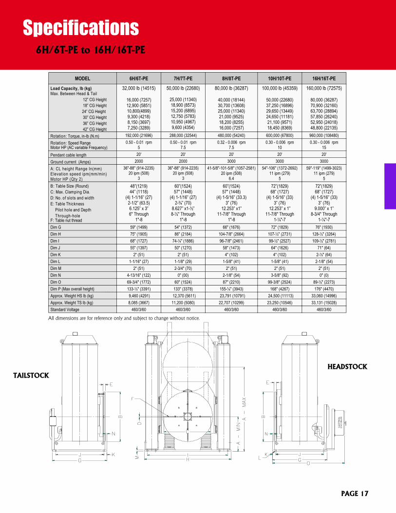
Specifications
***All dimensions are for reference only and subject to change without notice.
6H/6T-PE to 16H/16T-PE
MODEL 6H/6T-PE 7H/7T-PE 8H/8T-PE 10H/10T-PE 16H/16T-PE
Load Capacity, lb (kg)Max. Between Head & Tail 12” CG Height 18” CG Height 24” CG Height 30” CG Height 36” CG Height 42” CG Height
32,000 lb (14515)
16,000 (7257)12,900 (5851)10,800(4899)9,300 (4218)8,150 (3697)7,250 (3289)
50,000 lb (22680)
25,000 (11340)18,900 (8573)15,200 (6895)12,750 (5783)10,950 (4967)9,600 (4354)
80,000 lb (36287)
40,000 (18144)30,700 (13608)25,000 (11340)21,000 (9525)18,200 (8255)16,000 (7257)
100,000 lb (45359)
50,000 (22680)37,250 (16896)29,650 (13449)24,650 (11181)21,100 (9571)18,450 (8369)
160,000 lb (72575)
80,000 (36287)70,900 (32160)63,700 (28894)57,850 (26240)52,950 (24018)48,800 (22135)
Rotation: Torque, in-lb (N.m) 192,000 (21696) 288,000 (32544) 480,000 (54240) 600,000 (67800) 960,000 (108480)Rotation: Speed RangeMotor HP (AC variable Frequency)
0.50 - 0.01 rpm5
0.50 - 0.01 rpm7.5
0.32 - 0.006 rpm7.5
0.30 - 0.006 rpm10
0.30 - 0.006 rpm15
Pendant cable length 20' 20' 20' 20' 20'Ground current (Amps) 2000 2000 3000 3000 3000A: CL height Range In(mm)Elevation speed ipm(mm/min)Motor HP (Qty 2)
36"-88" (914-2235)20 ipm (508)
3
36"-88" (914-2235)20 ipm (508)
3
41-5/8"-101-5/8" (1057-2581)20 ipm (508)
6.4
54"-106" (1372-2692)11 ipm (279)
5
59"-119" (1499-3023)11 ipm (279)
5B: Table Size (Round)C: Max. Clamping Dia.D: No. of slots and widthE: Table Thickness
Pilot hole and DepthThrough-hole
F: Table nut thread
48”(1219)44” (1118)
(4) 1-1/16” (27)2-1/2” (63.5)6.125” x 3”6" Through
1"-8
60”(1524)57" (1448)
(4) 1-1/16” (27)2-¾” (70)
8.627” x1-½”8-½" Through
1"-8
60”(1524)57" (1448)
(4) 1-5/16” (33.3)3” (76)
12.253” x1”11-7/8" Through
1"-8
72”(1829)68” (1727)
(4) 1-5/16” (33)3” (76)
12.253” x 1”11-7/8" Through
1-¼"-7
72”(1829)68” (1727)
(4) 1-5/16” (33)3” (76)
9.000” x 1”8-3/4" Through
1-¼"-7Dim G 59" (1499) 54" (1372) 66" (1676) 72" (1829) 76" (1930)Dim H 75" (1905) 86" (2184) 104-7/8" (2664) 107-½" (2731) 128-½" (3264)Dim I 68" (1727) 74-¼" (1886) 96-7/8" (2461) 99-½" (2527) 109-½" (2781)Dim J 55" (1397) 50" (1270) 58" (1473) 64" (1626) 71" (64)Dim K 2" (51) 2" (51) 4" (102) 4" (102) 2-½" (64)Dim L 1-1/16" (27) 1-1/8" (29) 1-5/8" (41) 1-5/8" (41) 2-1/8" (54)Dim M 2" (51) 2-3/4" (70) 2" (51) 2" (51) 2" (51)Dim N 4-13/16" (122) 0" (00) 2-1/8" (54) 3-5/8" (92) 0" (0)Dim O 69-3/4" (1772) 60" (1524) 87" (2210) 99-3/8" (2524) 89-½" (2273)Dim P (Max overall height) 133-½" (3391) 133" (3378) 155-¼" (3943) 168" (4267) 176" (4470)Approx. Weight HS lb (kg) 9,460 (4291) 12,370 (5611) 23,791 (10791) 24,500 (11113) 33,060 (14996)Approx. Weight TS lb (kg) 8,085 (3667) 11,200 (5080) 22,707 (10299) 23,250 (10546) 33,131 (15028)Standard Voltage 460/3/60 460/3/60 460/3/60 460/3/60 460/3/60
All dimensions are for reference only and subject to change without notice.
HEADSTOCKTAILSTOCK
PAGE 17
KOIKE ARONSON, INC. / RANSOME
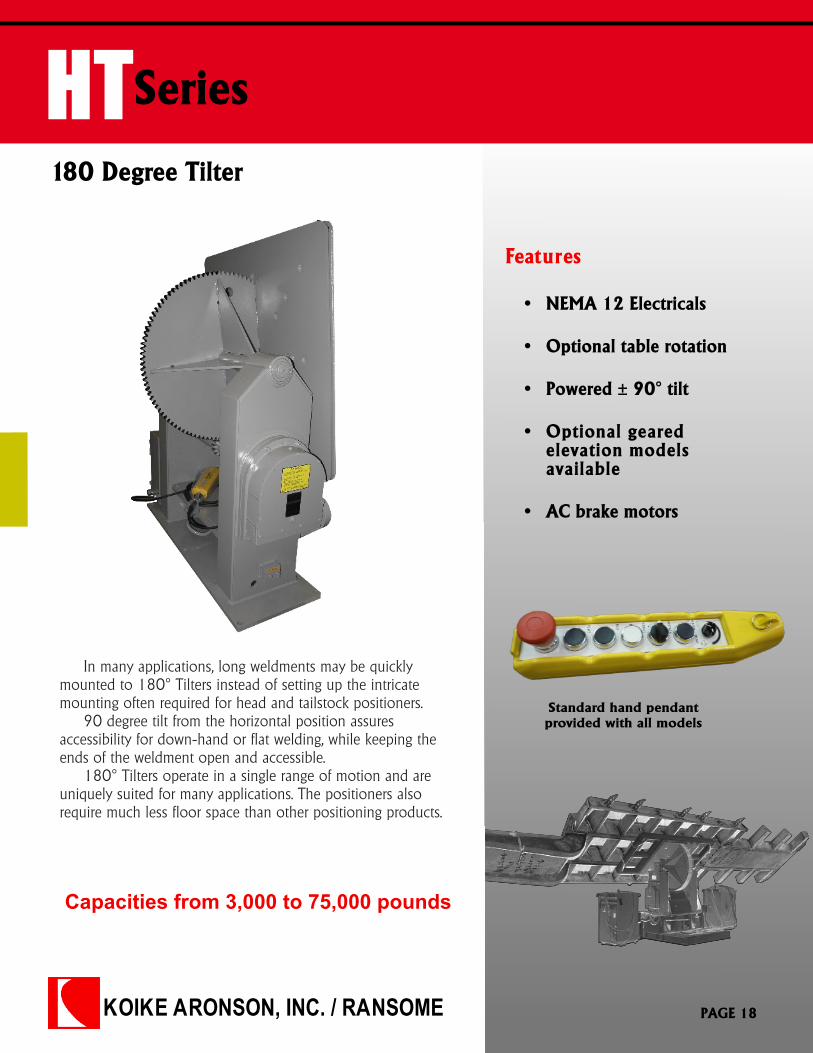
HTSeries
180 Degree Tilter
Features
In many applications, long weldments may be quicklymounted to 180° Tilters instead of setting up the intricatemounting often required for head and tailstock positioners.
90 degree tilt from the horizontal position assuresaccessibility for down-hand or flat welding, while keeping theends of the weldment open and accessible.
180° Tilters operate in a single range of motion and areuniquely suited for many applications. The positioners alsorequire much less floor space than other positioning products.
Standard hand pendantprovided with all models
Capacities from 3,000 to 75,000 pounds
� NEMA 12 Electricals
� Optional table rotation
� Powered ± 90° tilt
� Optional gearedelevation modelsavailable
� AC brake motors
PAGE 18
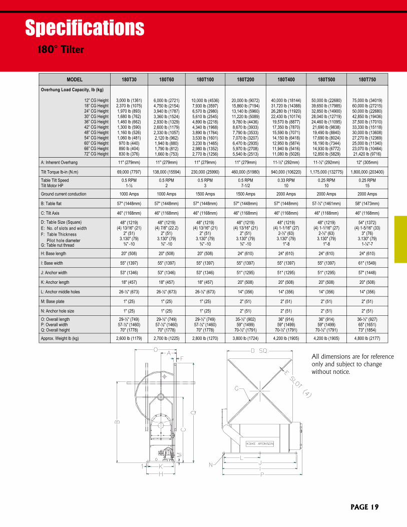
Specifications180° Tilter
All dimensions are for referenceonly and subject to changewithout notice.
MODEL 180T30 180T60 180T100 180T200 180T400 180T500 180T750
Overhung Load Capacity, lb (kg)
12” CG Height18” CG Height24” CG Height30” CG Height36” CG Height42” CG Height48” CG Height54” CG Height60” CG Height66” CG Height72” CG Height
3,000 lb (1361)2,370 lb (1075)1,970 lb (893)1,680 lb (762)1,460 lb (662)1,300 lb (590)1,160 lb (526)1,060 lb (481)970 lb (440)890 lb (404)830 lb (376)
6,000 lb (2721)4,750 lb (2154)3,940 lb (1787)3,360 lb (1524)2,930 lb (1329)2,600 lb (1179)2,330 lb (1057)2,120 lb (962)1,940 lb (880)1,790 lb (812)1,660 lb (753)
10,000 lb (4536)7,930 lb (3597)6,570 lb (2980)5,610 lb (2545)4,890 lb (2218)4,340 lb (1968)3,890 lb (1764)3,530 lb (1601)3,230 lb (1465)2,980 lb (1352)2,770 lb (1256)
20,000 lb (9072)15,860 lb (7194)13,140 lb (5960)11,220 lb (5089)9,780 lb (4436)8,670 lb (3933)7,790 lb (3533)7,070 lb (3207)6,470 lb (2935)5,970 lb (2708)5,540 lb (2513)
40,000 lb (18144)31,720 lb (14388)26,280 lb (11920)22,430 lb (10174)19,570 lb (8877)17,350 lb (7870)15,590 lb (7071)14,150 lb (6418)12,950 lb (5874)11,940 lb (5416)11,080 lb (5026)
50,000 lb (22680)39,650 lb (17985)32,850 lb (14900)28,040 lb (12719)24,460 lb (11095)21,690 lb (9838)19,490 lb (8840)17,690 lb (8024)16,190 lb (7344)14,930 lb (6772)12,850 lb (5829)
75,000 lb (34019)60,000 lb (27215)50,000 lb (22680)42,850 lb (19436)37,500 lb (17010)33,330 lb (15118)30,000 lb (13608)27,270 lb (12369)25,000 lb (11340)23,070 lb (10464)21,420 lb (9716)
A: Inherent Overhang 11" (279mm) 11" (279mm) 11" (279mm) 11" (279mm) 11-½" (292mm) 11-½" (292mm) 12" (305mm)
Tilt Torque lb-in (N.m) 69,000 (7797) 138,000 (15594) 230,000 (25990) 460,000 (51980) 940,000 (106220) 1,175,000 (132775) 1,800,000 (203400)
Table Tilt SpeedTilt Motor HP
0.5 RPM1-½
0.5 RPM2
0.5 RPM3
0.5 RPM7-1/2
0.33 RPM10
0.25 RPM10
0.25 RPM15
Ground current conduction 1000 Amps 1000 Amps 1500 Amps 1500 Amps 2000 Amps 2000 Amps 2000 Amps
B: Table flat 57" (1448mm) 57" (1448mm) 57" (1448mm) 57" (1448mm) 57" (1448mm) 57-½" (1461mm) 58" (1473mm)
C: Tilt Axis 46" (1168mm) 46" (1168mm) 46" (1168mm) 46" (1168mm) 46" (1168mm) 46" (1168mm) 46" (1168mm)
D: Table Size (Square)E: No. of slots and widthF: Table Thickness
Pilot hole diameterG: Table nut thread
48" (1219)(4) 13/16" (21)
2" (51)3.130" (79)
¾" -10
48" (1219)(4) 7/8" (22.2)
2" (51)3.130" (79)
¾" -10
48" (1219)(4) 13/16" (21)
2" (51)3.130" (79)
¾" -10
48" (1219)(4) 13/16" (21)
2" (51)3.130" (79)
¾" -10
48" (1219)(4) 1-1/16" (27)
2-½" (63)3.130" (79)
1"-8
48" (1219)(4) 1-1/16" (27)
2-½" (63)3.130" (79)
1"-8
54" (1372)(4) 1-5/16" (33)
3" (76)3.130" (79)
1-¼"-7
H: Base length 20" (508) 20" (508) 20" (508) 24" (610) 24" (610) 24" (610) 24" (610)
I: Base width 55" (1397) 55" (1397) 55" (1397) 55" (1397) 55" (1397) 55" (1397) 61" (1549)
J: Anchor width 53" (1346) 53" (1346) 53" (1346) 51" (1295) 51" (1295) 51" (1295) 57" (1448)
K: Anchor length 18" (457) 18" (457) 18" (457) 20" (508) 20" (508) 20" (508) 20" (508)
L: Anchor middle holes 26-½" (673) 26-½" (673) 26-½" (673) 14" (356) 14" (356) 14" (356) 14" (356)
M: Base plate 1" (25) 1" (25) 1" (25) 2" (51) 2" (51) 2" (51) 2" (51)
N: Anchor hole size 1" (25) 1" (25) 1" (25) 2" (51) 2" (51) 2" (51) 2" (51)
O: Overall lengthP: Overall widthQ: Overall height
29-½" (749)57-½" (1460)
70" (1778)
29-½" (749)57-½" (1460)
70" (1778)
29-½" (749)57-½" (1460)
70" (1778)
35-½" (902)59" (1499)
70-½" (1791)
36" (914)59" (1499)
70-½" (1791)
36" (914)59" (1499)
70-½" (1791)
36-½" (927)65" (1651)73" (1854)
Approx. Weight lb (kg) 2,600 lb (1179) 2,700 lb (1225) 2,800 lb (1270) 3,800 lb (1724) 4,200 lb (1905) 4,200 lb (1905) 4,800 lb (2177)
PAGE 19
KOIKE ARONSON, INC. / RANSOME
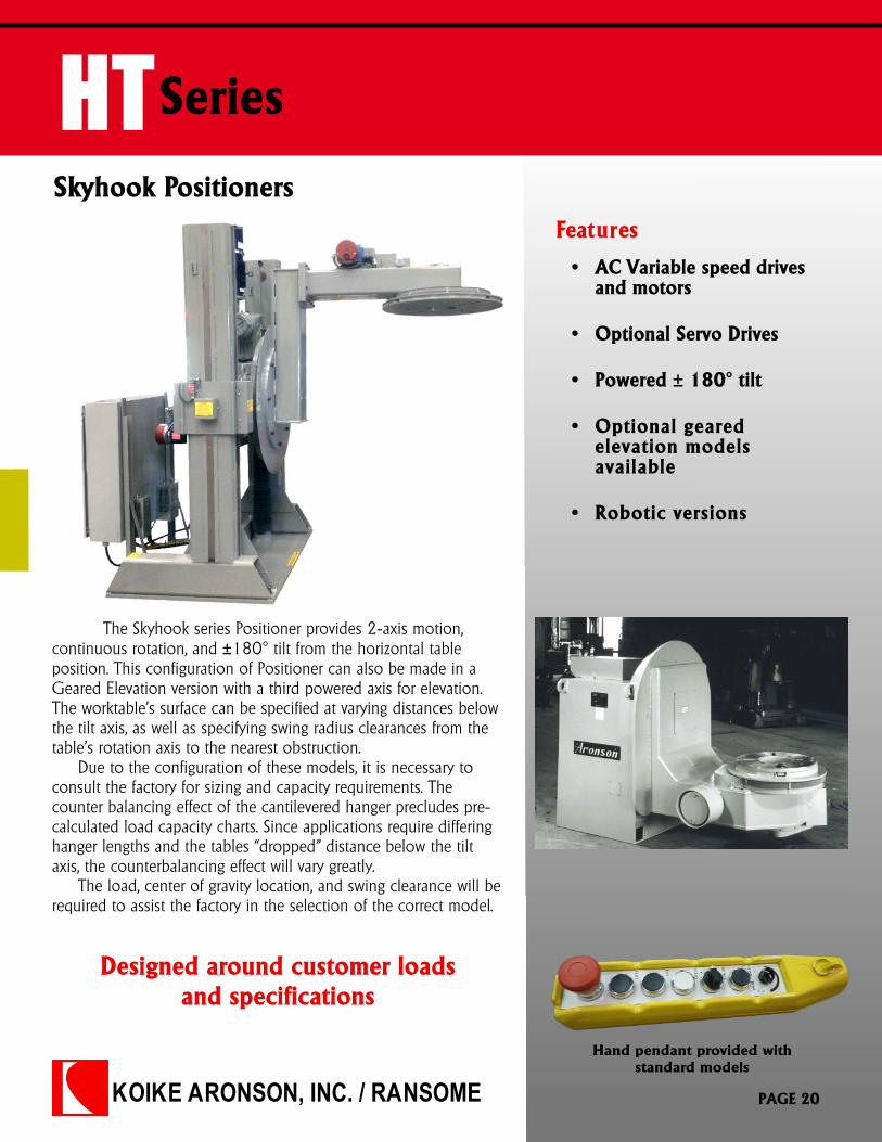
HTSeries
Skyhook PositionersFeatures
The Skyhook series Positioner provides 2-axis motion,continuous rotation, and ±180° tilt from the horizontal tableposition. This configuration of Positioner can also be made in aGeared Elevation version with a third powered axis for elevation.The worktable’s surface can be specified at varying distances belowthe tilt axis, as well as specifying swing radius clearances from thetable’s rotation axis to the nearest obstruction.
Due to the configuration of these models, it is necessary toconsult the factory for sizing and capacity requirements. Thecounter balancing effect of the cantilevered hanger precludes pre-calculated load capacity charts. Since applications require differinghanger lengths and the tables “dropped” distance below the tiltaxis, the counterbalancing effect will vary greatly.
The load, center of gravity location, and swing clearance will berequired to assist the factory in the selection of the correct model.
Hand pendant provided withstandard models
Designed around customer loadsand specifications
� AC Variable speed drivesand motors
� Optional Servo Drives
� Powered ± 180° tilt
� Optional gearedelevation modelsavailable
� Robotic versions
PAGE 20
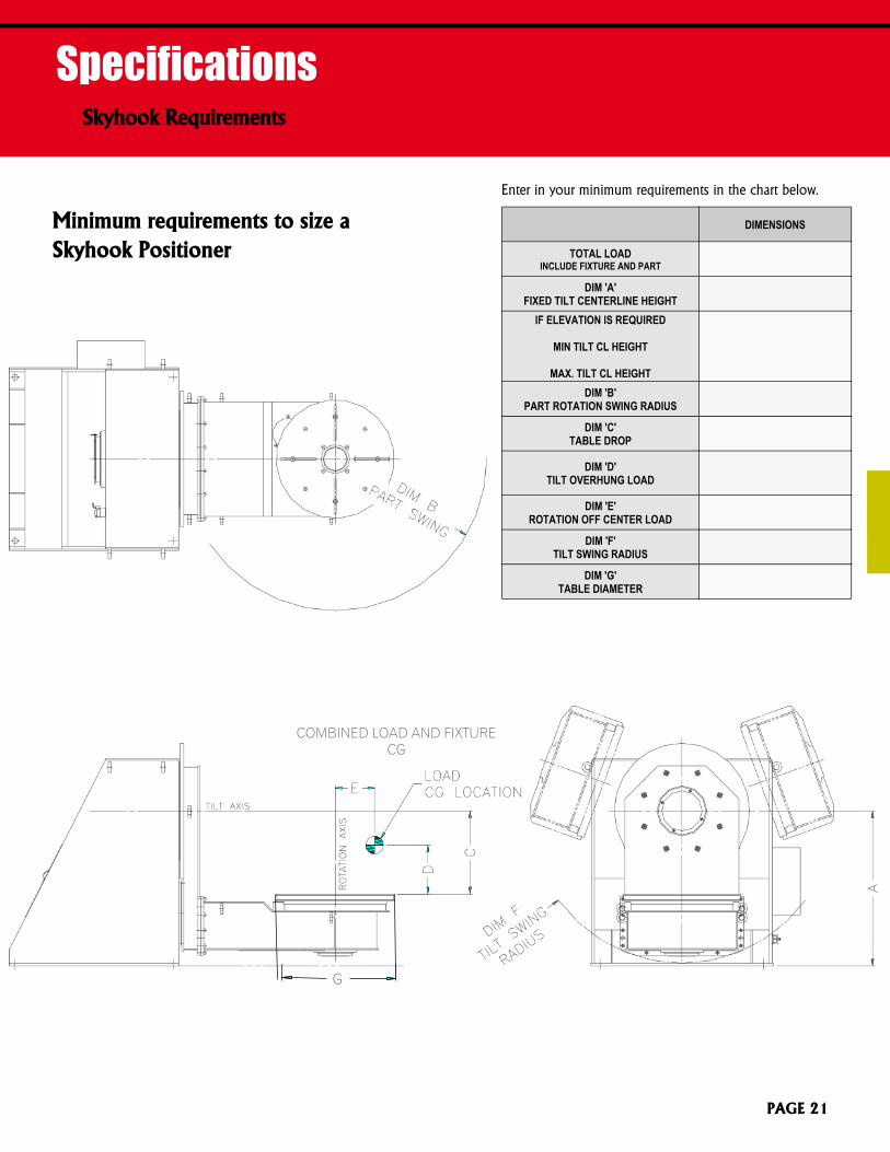
SpecificationsSkyhook Requirements
DIMENSIONS
TOTAL LOADINCLUDE FIXTURE AND PART
DIM 'A'FIXED TILT CENTERLINE HEIGHT
IF ELEVATION IS REQUIRED
MIN TILT CL HEIGHT
MAX. TILT CL HEIGHTDIM 'B'
PART ROTATION SWING RADIUS
DIM 'C'TABLE DROP
DIM 'D'TILT OVERHUNG LOAD
DIM 'E'ROTATION OFF CENTER LOAD
DIM 'F'TILT SWING RADIUS
DIM 'G'TABLE DIAMETER
Minimum requirements to size aSkyhook Positioner
PAGE 21
G
COMBINED LOAD AND FIXTURECG
KOIKE ARONSON, INC. / RANSOME
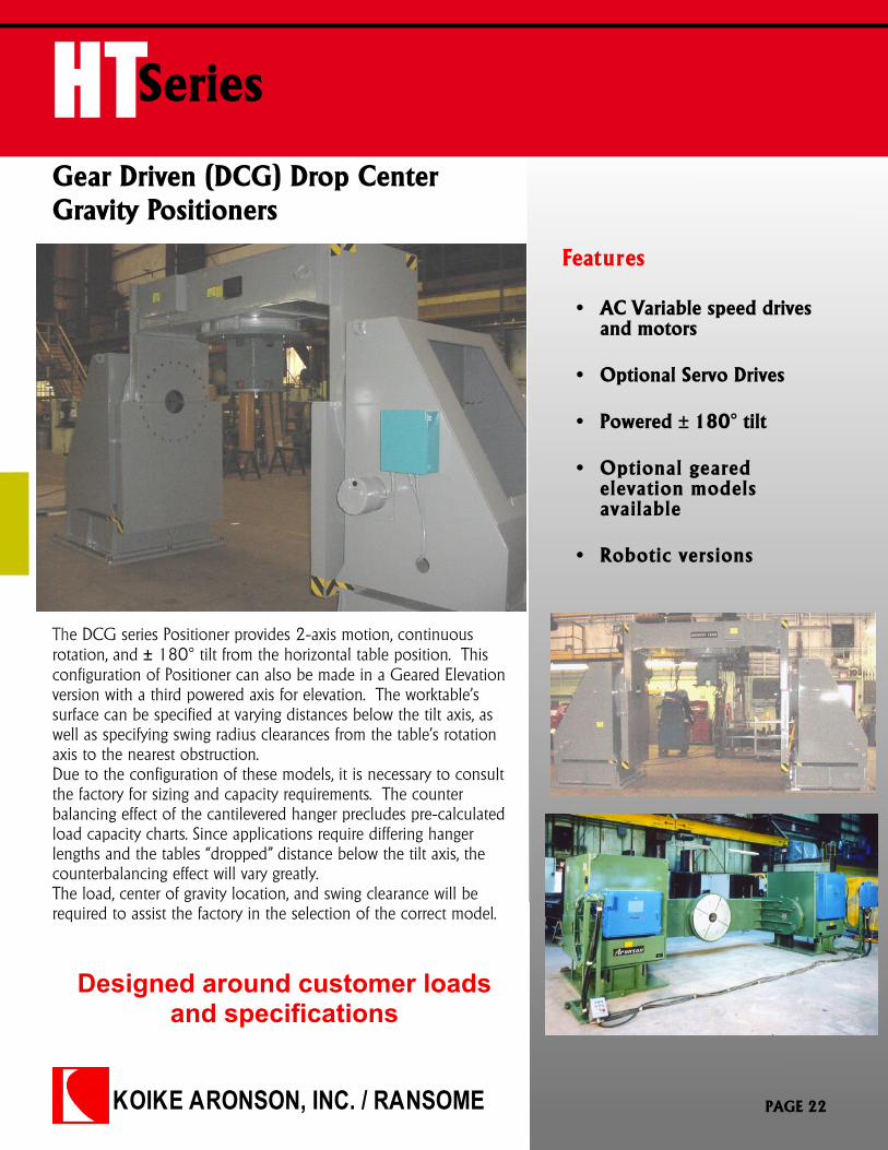
HTSeries
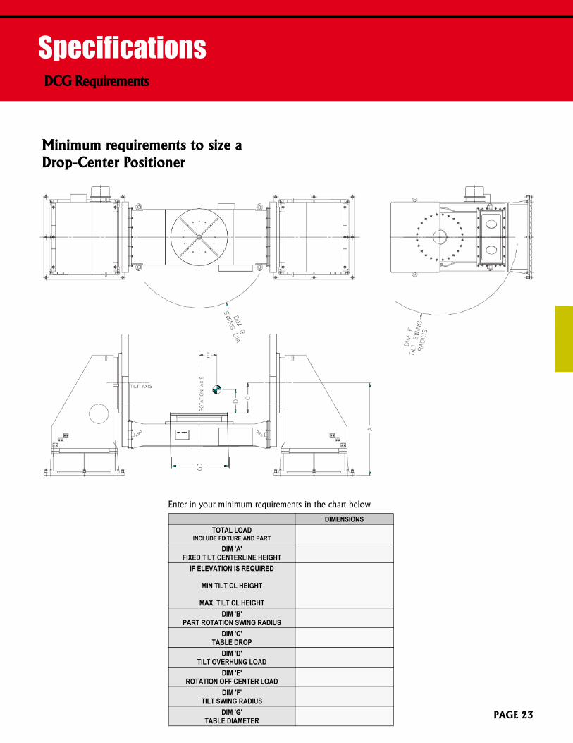
Gear Driven (DCG) Drop CenterGravity Positioners
Features
Designed around customer loadsand specifications
The DCG series Positioner provides 2-axis motion, continuousrotation, and ± 180° tilt from the horizontal table position. Thisconfiguration of Positioner can also be made in a Geared Elevationversion with a third powered axis for elevation. The worktable’ssurface can be specified at varying distances below the tilt axis, aswell as specifying swing radius clearances from the table’s rotationaxis to the nearest obstruction.Due to the configuration of these models, it is necessary to consultthe factory for sizing and capacity requirements. The counterbalancing effect of the cantilevered hanger precludes pre-calculatedload capacity charts. Since applications require differing hangerlengths and the tables “dropped” distance below the tilt axis, thecounterbalancing effect will vary greatly.The load, center of gravity location, and swing clearance will berequired to assist the factory in the selection of the correct model.
� AC Variable speed drivesand motors
� Optional Servo Drives
� Powered ± 180° tilt
� Optional gearedelevation modelsavailable
� Robotic versions
PAGE 22
SpecificationsDCG Requirements
Minimum requirements to size aDrop-Center Positioner
DIMENSIONSTOTAL LOAD
INCLUDE FIXTURE AND PARTDIM 'A'
FIXED TILT CENTERLINE HEIGHTIF ELEVATION IS REQUIRED
MIN TILT CL HEIGHT
MAX. TILT CL HEIGHTDIM 'B'
PART ROTATION SWING RADIUSDIM 'C'
TABLE DROPDIM 'D'
TILT OVERHUNG LOADDIM 'E'
ROTATION OFF CENTER LOADDIM 'F'
TILT SWING RADIUSDIM 'G'
TABLE DIAMETER PAGE 23
G
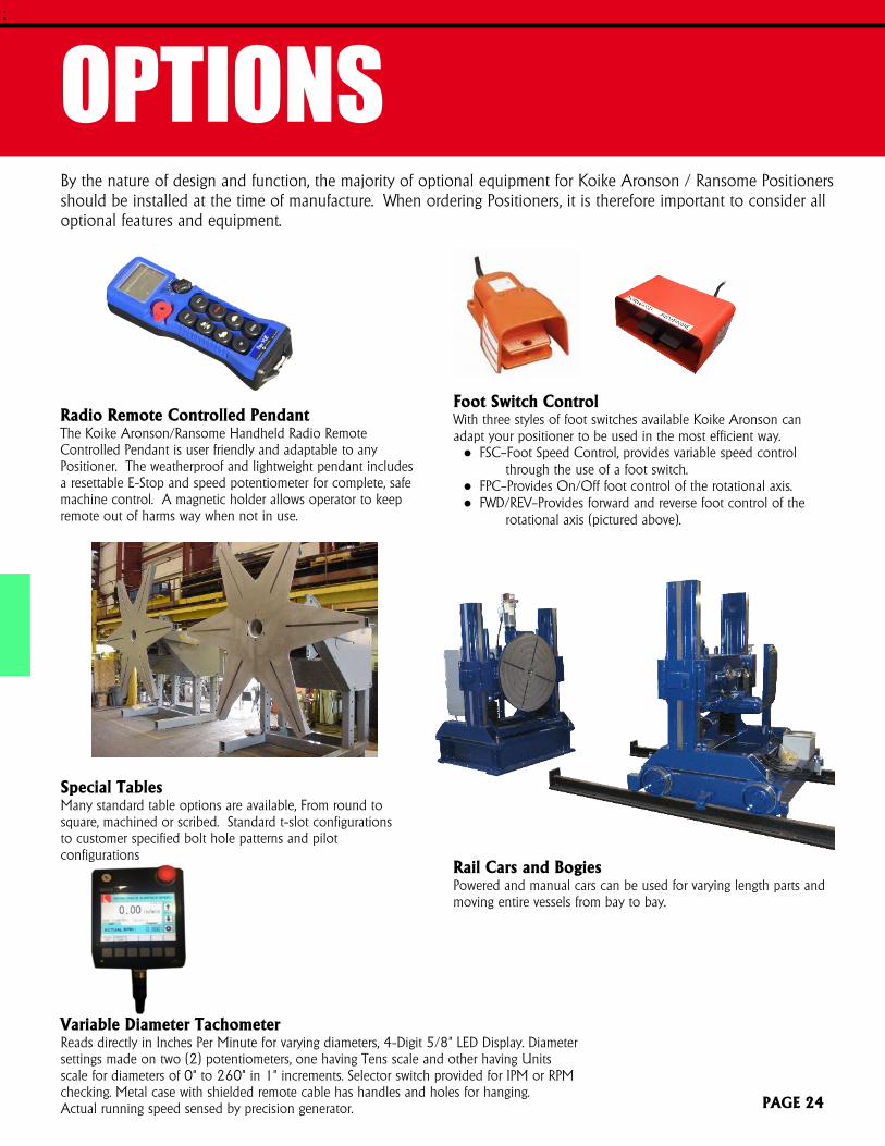
OPTIONSBy the nature of design and function, the majority of optional equipment for Koike Aronson / Ransome Positionersshould be installed at the time of manufacture. When ordering Positioners, it is therefore important to consider alloptional features and equipment.
:
Radio Remote Controlled PendantThe Koike Aronson/Ransome Handheld Radio RemoteControlled Pendant is user friendly and adaptable to anyPositioner. The weatherproof and lightweight pendant includesa resettable E-Stop and speed potentiometer for complete, safemachine control. A magnetic holder allows operator to keepremote out of harms way when not in use.
Special TablesMany standard table options are available, From round tosquare, machined or scribed. Standard t-slot configurationsto customer specified bolt hole patterns and pilotconfigurations
Variable Diameter TachometerReads directly in Inches Per Minute for varying diameters, 4-Digit 5/8" LED Display. Diametersettings made on two (2) potentiometers, one having Tens scale and other having Unitsscale for diameters of 0" to 260" in 1" increments. Selector switch provided for IPM or RPMchecking. Metal case with shielded remote cable has handles and holes for hanging.Actual running speed sensed by precision generator.
Foot Switch ControlWith three styles of foot switches available Koike Aronson canadapt your positioner to be used in the most efficient way.● FSC—Foot Speed Control, provides variable speed control
through the use of a foot switch.● FPC—Provides On/Off foot control of the rotational axis.● FWD/REV—Provides forward and reverse foot control of the
rotational axis (pictured above).
Rail Cars and BogiesPowered and manual cars can be used for varying length parts andmoving entire vessels from bay to bay.
PAGE 24
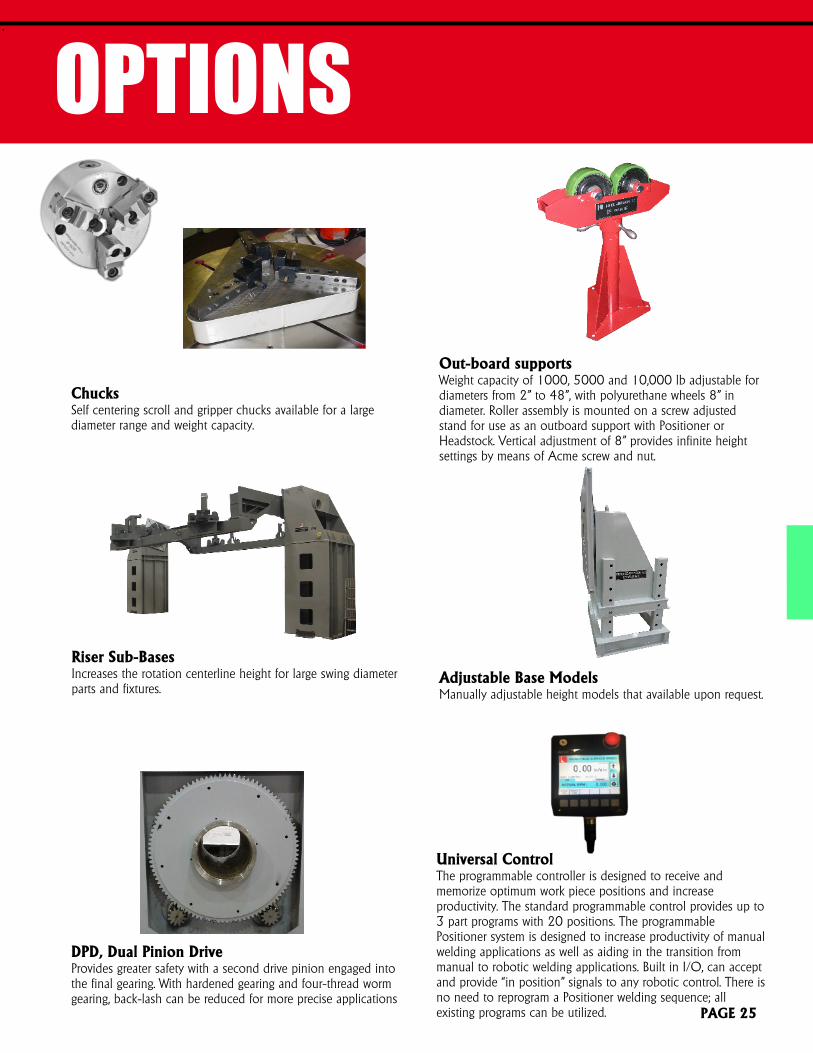
ChucksSelf centering scroll and gripper chucks available for a largediameter range and weight capacity.
Out-board supportsWeight capacity of 1000, 5000 and 10,000 lb adjustable fordiameters from 2” to 48”, with polyurethane wheels 8” indiameter. Roller assembly is mounted on a screw adjustedstand for use as an outboard support with Positioner orHeadstock. Vertical adjustment of 8” provides infinite heightsettings by means of Acme screw and nut.
OPTIONS:
Adjustable Base ModelsManually adjustable height models that available upon request.
Riser Sub-BasesIncreases the rotation centerline height for large swing diameterparts and fixtures.
DPD, Dual Pinion DriveProvides greater safety with a second drive pinion engaged intothe final gearing. With hardened gearing and four-thread wormgearing, back-lash can be reduced for more precise applications
PAGE 25
Universal ControlThe programmable controller is designed to receive andmemorize optimum work piece positions and increaseproductivity. The standard programmable control provides up to3 part programs with 20 positions. The programmablePositioner system is designed to increase productivity of manualwelding applications as well as aiding in the transition frommanual to robotic welding applications. Built in I/O, can acceptand provide “in position” signals to any robotic control. There isno need to reprogram a Positioner welding sequence; allexisting programs can be utilized.

NOTES
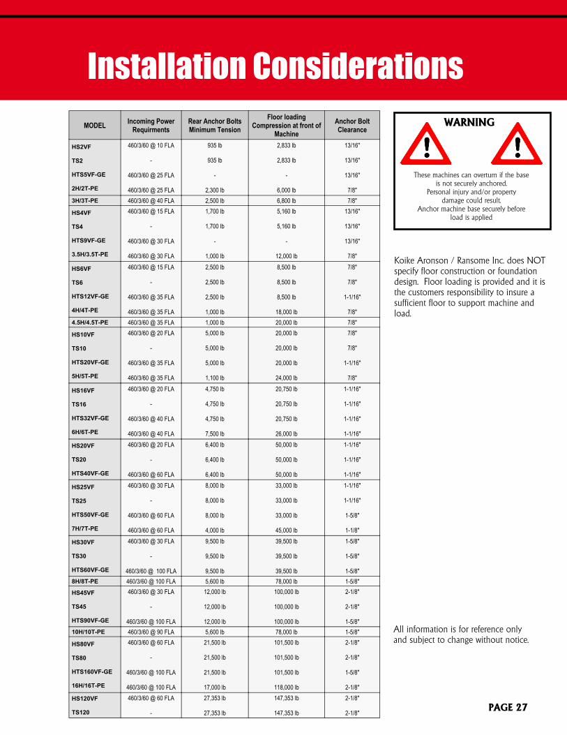
Installation ConsiderationsMODEL Incoming Power
RequirmentsRear Anchor BoltsMinimum Tension
Floor loadingCompression at front of
MachineAnchor BoltClearance
HS2VF
TS2
HTS5VF-GE
2H/2T-PE
460/3/60 @ 10 FLA
-
460/3/60 @ 25 FLA
460/3/60 @ 25 FLA
935 lb
935 lb
-
2,300 lb
2,833 lb
2,833 lb
-
6,000 lb
13/16"
13/16"
13/16"
7/8"3H/3T-PE 460/3/60 @ 40 FLA 2,500 lb 6,800 lb 7/8"
HS4VF
TS4
HTS9VF-GE
3.5H/3.5T-PE
460/3/60 @ 15 FLA
-
460/3/60 @ 30 FLA
460/3/60 @ 30 FLA
1,700 lb
1,700 lb
-
1,000 lb
5,160 lb
5,160 lb
-
12,000 lb
13/16"
13/16"
13/16"
7/8"
HS6VF
TS6
HTS12VF-GE
4H/4T-PE
460/3/60 @ 15 FLA
-
460/3/60 @ 35 FLA
460/3/60 @ 35 FLA
2,500 lb
2,500 lb
2,500 lb
1,000 lb
8,500 lb
8,500 lb
8,500 lb
18,000 lb
7/8"
7/8"
1-1/16"
7/8"4.5H/4.5T-PE 460/3/60 @ 35 FLA 1,000 lb 20,000 lb 7/8"
HS10VF
TS10
HTS20VF-GE
5H/5T-PE
460/3/60 @ 20 FLA
-
460/3/60 @ 35 FLA
460/3/60 @ 35 FLA
5,000 lb
5,000 lb
5,000 lb
1,100 lb
20,000 lb
20,000 lb
20,000 lb
24,000 lb
7/8"
7/8"
1-1/16"
7/8"
HS16VF
TS16
HTS32VF-GE
6H/6T-PE
460/3/60 @ 20 FLA
-
460/3/60 @ 40 FLA
460/3/60 @ 40 FLA
4,750 lb
4,750 lb
4,750 lb
7,500 lb
20,750 lb
20,750 lb
20,750 lb
26,000 lb
1-1/16"
1-1/16"
1-1/16"
1-1/16"
HS20VF
TS20
HTS40VF-GE
460/3/60 @ 20 FLA
-
460/3/60 @ 60 FLA
6,400 lb
6,400 lb
6,400 lb
50,000 lb
50,000 lb
50,000 lb
1-1/16"
1-1/16"
1-1/16"
HS25VF
TS25
HTS50VF-GE
7H/7T-PE
460/3/60 @ 30 FLA
-
460/3/60 @ 60 FLA
460/3/60 @ 60 FLA
8,000 lb
8,000 lb
8,000 lb
4,000 lb
33,000 lb
33,000 lb
33,000 lb
45,000 lb
1-1/16"
1-1/16"
1-5/8"
1-1/8"
HS30VF
TS30
HTS60VF-GE
460/3/60 @ 30 FLA
-
460/3/60 @ 100 FLA
9,500 lb
9,500 lb
9,500 lb
39,500 lb
39,500 lb
39,500 lb
1-5/8"
1-5/8"
1-5/8"8H/8T-PE 460/3/60 @ 100 FLA 5,600 lb 78,000 lb 1-5/8"HS45VF
TS45
HTS90VF-GE
460/3/60 @ 30 FLA
-
460/3/60 @ 100 FLA
12,000 lb
12,000 lb
12,000 lb
100,000 lb
100,000 lb
100,000 lb
2-1/8"
2-1/8"
1-5/8"10H/10T-PE 460/3/60 @ 90 FLA 5,600 lb 78,000 lb 1-5/8"
HS80VF
TS80
HTS160VF-GE
16H/16T-PE
460/3/60 @ 60 FLA
-
460/3/60 @ 100 FLA
460/3/60 @ 100 FLA
21,500 lb
21,500 lb
21,500 lb
17,000 lb
101,500 lb
101,500 lb
101,500 lb
118,000 lb
2-1/8"
2-1/8"
1-5/8"
2-1/8"HS120VF
TS120
460/3/60 @ 60 FLA
-
27,353 lb
27,353 lb
147,353 lb
147,353 lb
2-1/8"
2-1/8"
All information is for reference onlyand subject to change without notice.
WARNING
These machines can overturn if the baseis not securely anchored.
Personal injury and/or propertydamage could result.
Anchor machine base securely beforeload is applied
Koike Aronson / Ransome Inc. does NOTspecify floor construction or foundationdesign. Floor loading is provided and it isthe customers responsibility to insure asufficient floor to support machine andload.
PAGE 27
HEADSTOCK/TAILSTOCK 01/18 KENG
Koike Aronson, Inc./Ransome
635 W. Main StreetP.O. Box 307
Arcade, NY 14009
Phone: (585) 492-2400Fax: (585) 457-3517
Toll Free: (800) 252-5232
www.koike.com
Koike Aronson Brasil
Rua Agostinho Mazza N° 31Bairro Parque do Trevo
Jaboticabal - SPCEP 14871-710
Tel/Fax: (16) 3202-8439
www.koike.com/br