Embed Size (px)
Citation preview
26TH
INTERNATIONAL CONGRESS OF THE AERONAUTICAL SCIENCES
1
Abstract
This paper discusses structure and
functionalities of a Knowledge Based
Engineering application, called Multi Model
Generator (MMG), developed to support
aircraft multidisciplinary design, analysis and
optimisation. Designers can use the MMG as an
advanced modeling tool to swiftly generate
geometrical models of many and diverse
aircraft configurations and variants, by
combining and adjusting a limited number of
parametric objects, called High Level
Primitives. Besides capturing the geometric
aspects of design, the MMG has also the
capabilities to automate large part of the
lengthy and non-creative preprocessing
activities involved in the design verification
process. The proposed KBE application has
demonstrated to be a valuable solution for some
of the critical needs indicated by the MDO
community, namely: a flexible and robust
generative tool to increase the level of
automation in aircraft design, including the
development of novel configurations; the
exploitation of high fidelity analysis tools
already in the early design phases; the
management of the design activities across
distributed networks of disciplines specialists.
1 Introduction
Despite the great advances in computer
technology and the continuously increasing
capabilities of computer aided engineering
tools, innovation in aircraft design is actually
restrained by the lack of fully adequate design
methodologies [1]. Improved design approaches
and supporting design technologies are required
to keep enhancing the design of current aircraft
configurations, as well as to investigate novel
air vehicle concepts, such as blended wing
bodies and joint wing configurations [2,3]. The
ACARE Strategic Research Agenda [4]
envisions a future scenario, where next 20 years
aircraft will differ from those of today, as much
as the latter differ from those of the 30ies. How
this can happen in the rather conservative civil
aviation sector, is very difficult to imagine.
First, new design technologies will have to be
developed aiming at lowering the risk
associated with the development of new and
unconventional configuration. Indeed, before
committing to any radical innovation, there is
the need to generate adequate knowledge of new
concepts by means of detailed multidisciplinary
analysis and simulations.
In this sense, the Multidisciplinary Design
and Optimisation (MDO) approach seems to be
the most promising so far. However, after 15-20
years of tools and methodologies development
for an effective, efficient and systematic
exploration of the design space [5,6], large scale
exploitation of MDO at industry level is not yet
a reality. Many are still the barriers, not only of
technical nature, that are constraining MDO
application to limited cases [7-9]. The concepts
of lean engineering, originated in the area of
production and manufacturing, need to be
adopted also in the design process, where there
is still a large unbalance (in the order of
20:80%) between the time dedicated to creative
work and that consumed by the lengthy and
repetitive activities associated to data and
models processing. In order to exploit such a
KNOWLEDGE BASED ENGINEERING TO SUPPORT AIRCRAFT MULTIDISCIPLINARY DESIGN AND
OPTIMISATION
Gianfranco La Rocca and Michel J.L. van Tooren
Delft University of Technology
Keywords: KBE, MDO, Aircraft Design, Multi Model Generator, High Level Primitives
G. LA ROCCA, M.J.L. VAN TOOREN
2
discipline as MDO, which by definition requires
many iterations of (re)design and analysis
processes, improving the level of automation is
a fundamental goal.
According to the authors, knowledge based
engineering (KBE) technology has the potential
to address exactly the abovementioned
criticalities. As more extensively elaborated in
[10-14], KBE can be defined as a technology
that allows capturing and reusing product and
process multidisciplinary knowledge in an
integrated way, in order to reduce time and costs
for engineering applications, through the
automation of the repetitive design activities.
Actually, within large aircraft companies, like
Boeing, Lockheed Martin and Airbus, KBE is
already a mainstream technology since years.
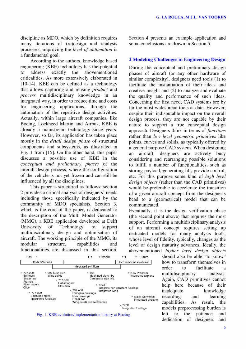
However, so far, its application has taken place
mostly in the detail design phase of structural
components and subsystems, as illustrated in
Fig. 1 from [15]. On the other hand, this paper
discusses a possible use of KBE in the
conceptual and preliminary phases of the
aircraft design process, where the configuration
of the vehicle is not yet frozen and can still be
influenced by all the disciplines.
This paper is structured as follows: section
2 provides a critical analysis of designers’ needs
including those specifically indicated by the
community of MDO specialists. Section 3,
which is the core of the paper, is dedicated to
the description of the Multi Model Generator
(MMG), a KBE application developed at Delft
University of Technology, to support
multidisciplinary design and optimisation of
aircraft. The working principle of the MMG, its
modular structure, capabilities and
functionalities are discussed in this section.
Section 4 presents an example application and
some conclusions are drawn in Section 5.
2 Modeling Challenges in Engineering Design
During the conceptual and preliminary design
phases of aircraft (or any other hardware of
similar complexity), designers need tools (1) to
facilitate the instantiation of their ideas and
creative insight and (2) to analyze and evaluate
the quality and performance of such ideas.
Concerning the first need, CAD systems are by
far the most widespread tools at date. However,
despite their indisputable impact on the overall
design process, they are not capable by their
nature to support a true conceptual design
approach. Designers think in terms of functions
rather than low level geometric primitives like
points, curves and solids, as typically offered by
a general purpose CAD system. When designing
an aircraft, designers are actively busy
considering and rearranging possible solutions
to fulfill a number of functionalities, such as
storing payload, generating lift, provide control,
etc. For this purpose some kind of high level
design objects (rather than the CAD primitives)
would be preferable to accelerate the transition
of a given aircraft concept from the designer’s
head to a (geometrical) model that can be
communicated.
Eventually, it is the design verification phase
(the second point above) that requires the most
support. Performing a multidisciplinary analysis
of an aircraft concept requires setting up
dedicated models for many analysis tools,
whose level of fidelity, typically, changes as the
level of design maturity advances. Ideally, the
abovementioned higher level design objects
should also be able “to know”
how to transform themselves in
order to facilitate a
multidisciplinary analysis.
Again, CAD primitives cannot
help here because of their
inadequate knowledge
recording and learning
capabilities. As result, the
models preprocessing burden is
left to the patience and
dedication of designers and Fig. 1. KBE evolution/implementation history at Boeing

3
KNOWLEDGE BASED ENGINEERING TO SUPPORT AIRCRAFT MDO
analysts. Indeed, the multidisciplinary modeling
capability is one of the most critical aspects of
MDO:
• The generation of dedicated models is
required both for low and high fidelity
analysis tools. The latter in particular are
the most critical and difficult to automate,
whereas their use is essential to assess the
design of new unconventional aircraft
concept.
• Models are required both for commercial of
the shelf and in house developed analysis
tools. Typically, the latter excel in terms of
computation performance, but lack in term
of preprocessing and interfacing capability.
• Models must be tailored to the different
views of the discipline specialists (and their
tools). However, they have to be
synchronized, consistent and coherent.
• To support the iterative nature of the MDO
design, models should be generated on the
fly, hands off and be accessible in remote
both to human operators and/or software
optimizing tools. This is an operational
prerequisite to any distributed MDO
framework.
The challenges discussed so far have actually
provided the use case for the development of
the Multi Model Generator, an advanced
modeling system developed at TU Delft to
support aircraft multidisciplinary design and
optimisation.
3 The Aircraft Multi Model Generator:
Working Principles, Internal Structure and
Functionality
The higher level design objects envisioned in
section 2 and their capability to transform
themselves in suitable models to feed
multidisciplinary analysis, represent actually the
fundamental concepts at the base of the Multi
Model Generator (MMG). In fact, the MMG
provides designers with a suite of parametric
functional objects, the so called High Level
Primitives (HLPs), which can be adjusted and
assembled to build up an extremely large
number of aircraft configurations, including
novel air vehicle concepts, and an infinite
amount of variants. See the concept illustrated
in Fig. 2 (more in 3.1 and 3.2). Furthermore, a
number of so called Capabilities Modules
(CMs) has been defined, where the engineering
knowledge to process the HLPs geometry into
suitable models/formats for various analysis
tools has been captured for systematic reuse
(more in 3.3).
The MMG has been developed using a
commercial Knowledge Based Engineering
system. Considering the “high concentration”
of ingredients such as geometry manipulation,
generative modeling, capture and reuse of
engineering knowledge, KBE just appeared to
be the most suitable technology at hand [10-14].
Fig. 2. The High Level Primitives build up approach
HLPs
G. LA ROCCA, M.J.L. VAN TOOREN
4
3.1 The High Level Primitives Modeling
Approach: Capturing Product Similarities
Though a traditional airliner and a blended wing
body aircraft appear to have a very different
configuration, they both feature similar
components, which embody given
functionalities like generating lift, supplying
thrust and accommodating payload. Though
these components have a different shape and are
combined in different topological
configurations, it is still possible to spot the
recurrent presence of wing-like elements,
fuselage sections, engines and connection parts
as shown if Fig. 2. For each of these four
entities, a so-called High Level Primitive has
been implemented in the KBE system. Using
the supplied lisp-based objected oriented
language, each HLP has been defined as a class
(see more in section 3.3). When a set of
parameters values is provided to the given class,
a unique instantiation is dynamically generated.
Eventually, the HLPs can be considered as a
kind of rubber LEGO® blocks, which can be
individually morphed due to their parametric
definition and assembled to build-up a
potentially infinite range of different aircraft
configurations and variants. Indeed, the
parameters used to define the various HLPs
represent the actual degrees of freedom of the
HLP and determine the typicality-range
of the specific instantiations that can be
generated [16].
3.1.1 Definition of the Aircraft Outer
Shape
The surfaces of the various aircraft
shown in Fig. 2 have been generated
using a different number of HLPs’
instantiations and assigning different
values to the parameters that specify
their external shape. In case of the
Wing-Trunk primitive, for example,
some of the shape parameters are span
and chords’ length, sweep and twist
angles, number, location and type of
airfoils. In order to model a wing-like
system with the MMG, the designer
must specify the number and shape of
the required Wing Trunk instantiations, whereas
the number and the shape of the various
connection elements are automatically
determined by the MMG, in order to guarantee a
smooth and water-tight wing surface. The
connection-element HLP “knows” if its
presence is required (e.g., in case adjacent wing-
trunks are defined with different dihedral
angles) and, in case, the required shape (which
is based on the geometry of the adjacent wing
trunks to be blended).
3.1.2 Definition of Aircraft Structure and
Systems
The definition of the HLPs is not just limited to
the parametric description of the aerodynamic
surfaces, but includes also the internal structure.
Number, position and orientation of main
structural elements like spars, rib, riblets,
frames, stringers and floors are defined
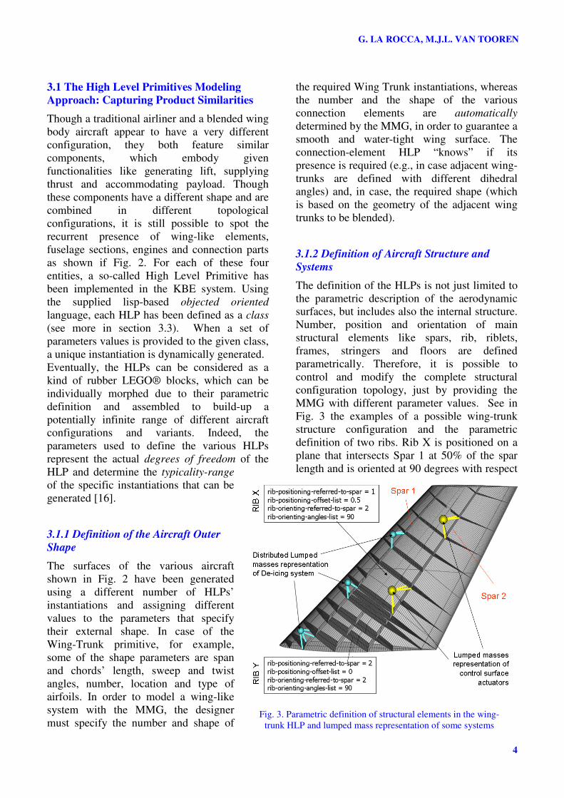
parametrically. Therefore, it is possible to
control and modify the complete structural
configuration topology, just by providing the
MMG with different parameter values. See in
Fig. 3 the examples of a possible wing-trunk
structure configuration and the parametric
definition of two ribs. Rib X is positioned on a
plane that intersects Spar 1 at 50% of the spar
length and is oriented at 90 degrees with respect
Fig. 3. Parametric definition of structural elements in the wing-
trunk HLP and lumped mass representation of some systems
5
KNOWLEDGE BASED ENGINEERING TO SUPPORT AIRCRAFT MDO
to the direction of Spar 2. Rib Y is positioned
on a plane that passes through the root of Spar 2
(0% of Spar 2 length) and is oriented at 90
degrees with respect to the same Spar 2.
A remarkable feature of the MMG is the
associative definition of the internal structure
with respect to the HLPs outer surface. I.e.,
when the aerodynamic shape of the aircraft
changes (e.g., because of the implementation of
different airfoils or fuselage cross sections) the
shape (and, in case, the topology) of the
airframe automatically changes and adapt to the
new mould line.
Apart form the outer shape and internal
structure, the HLPs offer also the possibility to
model the main aircraft systems (e.g., landing
gears, APU, engines and actuators), as needed
both for structural analysis and for the weight
and balance discipline. All these systems are
modeled as simple sets of lumped masses,
which is just adequate to the needs of
conceptual/preliminary studies. In addiction, the
HLPs take care of the connectivity of the
various aircraft systems by automating the
generation of attachment links between the
lumped masses and selected airframe
components. See in Fig. 3 modeling examples
of the de-icing and actuators system inside a
wing-trunk. When the topology of the airframe
changes (because of changes in the number
and/or location of spars, ribs and
floor beams, for example), both
position and connectivity of the
aircraft systems automatically adapt,
because defined by means of
parametric and logic rules, stored in
the HLPs.
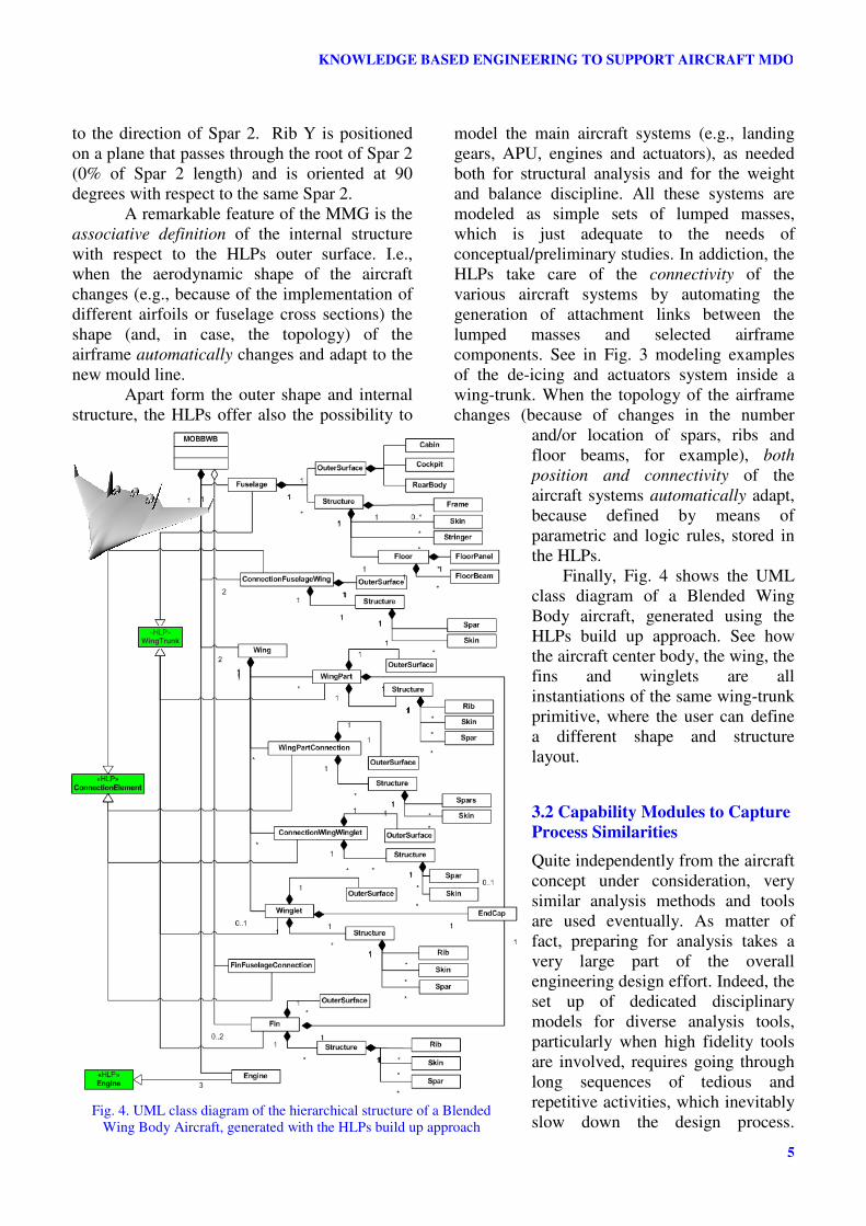
Finally, Fig. 4 shows the UML
class diagram of a Blended Wing
Body aircraft, generated using the
HLPs build up approach. See how
the aircraft center body, the wing, the
fins and winglets are all
instantiations of the same wing-trunk
primitive, where the user can define
a different shape and structure
layout.
3.2 Capability Modules to Capture
Process Similarities
Quite independently from the aircraft
concept under consideration, very
similar analysis methods and tools
are used eventually. As matter of
fact, preparing for analysis takes a
very large part of the overall
engineering design effort. Indeed, the
set up of dedicated disciplinary
models for diverse analysis tools,
particularly when high fidelity tools
are involved, requires going through
long sequences of tedious and
repetitive activities, which inevitably
slow down the design process. Fig. 4. UML class diagram of the hierarchical structure of a Blended
Wing Body Aircraft, generated with the HLPs build up approach
«HLP» WingTrunk
G. LA ROCCA, M.J.L. VAN TOOREN
6
However, the good news is that a large part of
these activities is very well suitable to be
formalized into sets of generic rules and
algorithms, which can be captured into KBE
applications. After some knowledge acquisition
sessions with discipline experts to elicit their
working practice, tips and tricks [14], a number
of so called Capability Modules (CMs) has been
programmed using the supplied KBE language.
The CMs are classes with the peculiarity to
encapsulate just procedural knowledge, i.e.,
they cannot be instantiated into geometric
objects like the HLPs do, however, they have
the capability to operate on the geometric data
generated by the HLPs. Eventually, the CMs are
able to automatically process the geometry of
the various HLPs instantiations and support the
preparation of the specific models required by
the discipline tools. Examples of capability
modules are SurfaceSplitter and
PointsGenerator, which are used, respectively,
to transform the geometry of the HLPs in sets of
meshable surfaces for FE analysis (see details in
[17]) and set of points/panels to support the
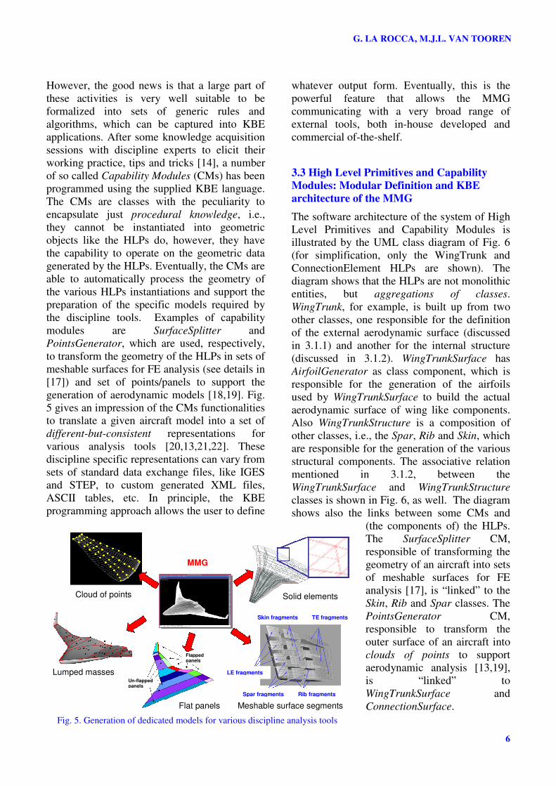
generation of aerodynamic models [18,19]. Fig.
5 gives an impression of the CMs functionalities
to translate a given aircraft model into a set of
different-but-consistent representations for
various analysis tools [20,13,21,22]. These
discipline specific representations can vary from
sets of standard data exchange files, like IGES
and STEP, to custom generated XML files,
ASCII tables, etc. In principle, the KBE
programming approach allows the user to define
whatever output form. Eventually, this is the
powerful feature that allows the MMG
communicating with a very broad range of
external tools, both in-house developed and
commercial of-the-shelf.
3.3 High Level Primitives and Capability
Modules: Modular Definition and KBE
architecture of the MMG
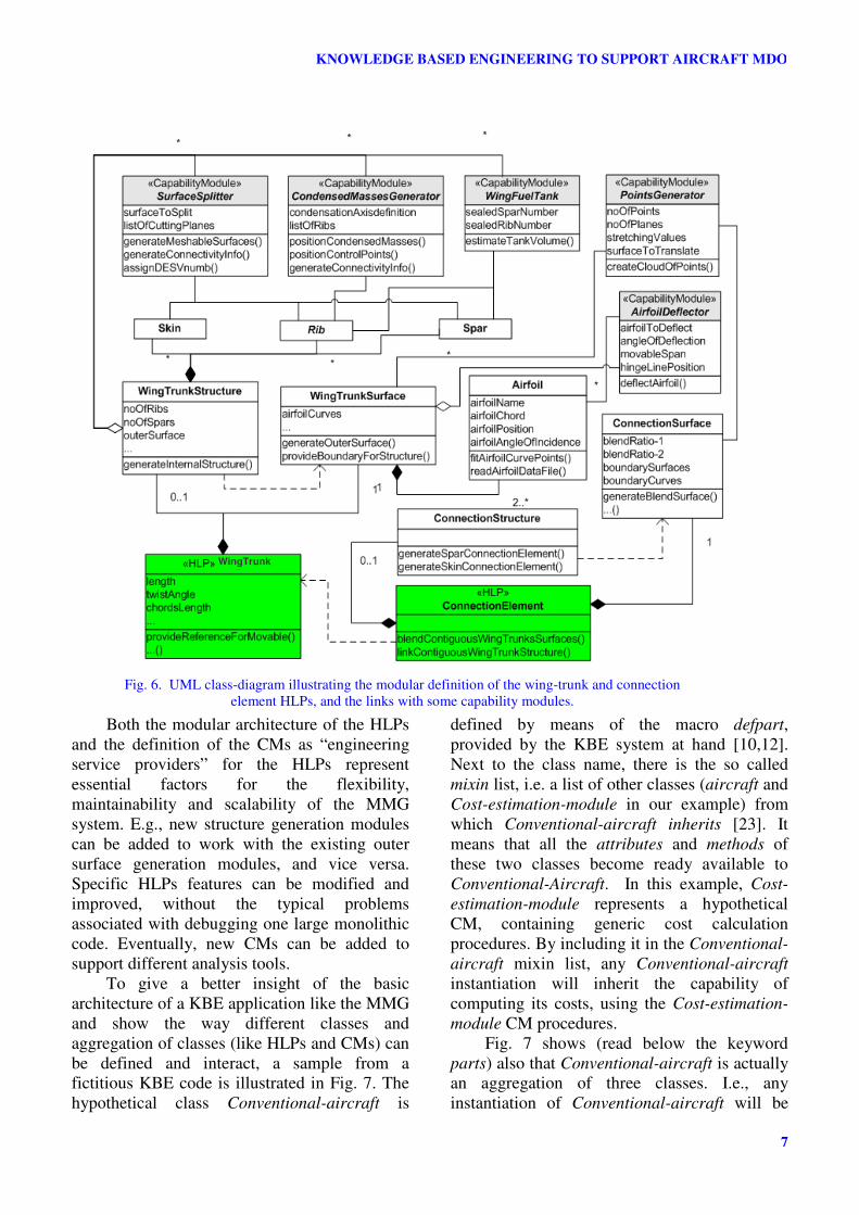
The software architecture of the system of High
Level Primitives and Capability Modules is
illustrated by the UML class diagram of Fig. 6
(for simplification, only the WingTrunk and
ConnectionElement HLPs are shown). The
diagram shows that the HLPs are not monolithic
entities, but aggregations of classes.
WingTrunk, for example, is built up from two
other classes, one responsible for the definition
of the external aerodynamic surface (discussed
in 3.1.1) and another for the internal structure
(discussed in 3.1.2). WingTrunkSurface has
AirfoilGenerator as class component, which is
responsible for the generation of the airfoils
used by WingTrunkSurface to build the actual
aerodynamic surface of wing like components.
Also WingTrunkStructure is a composition of
other classes, i.e., the Spar, Rib and Skin, which
are responsible for the generation of the various
structural components. The associative relation
mentioned in 3.1.2, between the
WingTrunkSurface and WingTrunkStructure
classes is shown in Fig. 6, as well. The diagram
shows also the links between some CMs and
(the components of) the HLPs.
The SurfaceSplitter CM,
responsible of transforming the
geometry of an aircraft into sets
of meshable surfaces for FE
analysis [17], is “linked” to the
Skin, Rib and Spar classes. The
PointsGenerator CM,
responsible to transform the
outer surface of an aircraft into
clouds of points to support
aerodynamic analysis [13,19],
is “linked” to
WingTrunkSurface and
ConnectionSurface.
Fig. 5. Generation of dedicated models for various discipline analysis tools
Cloud of points
Lumped masses
Flat panels Meshable surface segments
Solid elements
MMG
Skin fragments TE fragments
Spar fragments Rib fragments
LE fragments
Un-flapped panels
Flapped panels
7
KNOWLEDGE BASED ENGINEERING TO SUPPORT AIRCRAFT MDO
Both the modular architecture of the HLPs
and the definition of the CMs as “engineering
service providers” for the HLPs represent
essential factors for the flexibility,
maintainability and scalability of the MMG
system. E.g., new structure generation modules
can be added to work with the existing outer
surface generation modules, and vice versa.
Specific HLPs features can be modified and
improved, without the typical problems
associated with debugging one large monolithic
code. Eventually, new CMs can be added to
support different analysis tools.
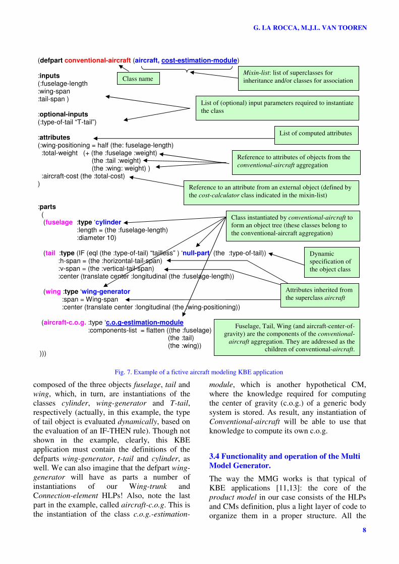
To give a better insight of the basic
architecture of a KBE application like the MMG
and show the way different classes and
aggregation of classes (like HLPs and CMs) can
be defined and interact, a sample from a
fictitious KBE code is illustrated in Fig. 7. The
hypothetical class Conventional-aircraft is
defined by means of the macro defpart,
provided by the KBE system at hand [10,12].
Next to the class name, there is the so called
mixin list, i.e. a list of other classes (aircraft and
Cost-estimation-module in our example) from
which Conventional-aircraft inherits [23]. It
means that all the attributes and methods of
these two classes become ready available to
Conventional-Aircraft. In this example, Cost-
estimation-module represents a hypothetical
CM, containing generic cost calculation
procedures. By including it in the Conventional-
aircraft mixin list, any Conventional-aircraft
instantiation will inherit the capability of
computing its costs, using the Cost-estimation-
module CM procedures.
Fig. 7 shows (read below the keyword
parts) also that Conventional-aircraft is actually
an aggregation of three classes. I.e., any
instantiation of Conventional-aircraft will be
Fig. 6. UML class-diagram illustrating the modular definition of the wing-trunk and connection
element HLPs, and the links with some capability modules.
WingTrunk
G. LA ROCCA, M.J.L. VAN TOOREN
8
composed of the three objects fuselage, tail and
wing, which, in turn, are instantiations of the
classes cylinder, wing-generator and T-tail,
respectively (actually, in this example, the type
of tail object is evaluated dynamically, based on
the evaluation of an IF-THEN rule). Though not
shown in the example, clearly, this KBE
application must contain the definitions of the
defparts wing-generator, t-tail and cylinder, as
well. We can also imagine that the defpart wing-
generator will have as parts a number of
instantiations of our Wing-trunk and
Connection-element HLPs! Also, note the last
part in the example, called aircraft-c.o.g. This is
the instantiation of the class c.o.g.-estimation-
module, which is another hypothetical CM,
where the knowledge required for computing
the center of gravity (c.o.g.) of a generic body
system is stored. As result, any instantiation of
Conventional-aircraft will be able to use that
knowledge to compute its own c.o.g.
3.4 Functionality and operation of the Multi
Model Generator.
The way the MMG works is that typical of
KBE applications [11,13]: the core of the
product model in our case consists of the HLPs
and CMs definition, plus a light layer of code to
organize them in a proper structure. All the
(defpart conventional-aircraft (aircraft, cost-estimation-module) :inputs (:fuselage-length :wing-span :tail-span ) :optional-inputs (:type-of-tail “T-tail”) :attributes (:wing-positioning = half (the: fuselage-length) :total-weight (+ (the :fuselage :weight) (the :tail :weight) (the :wing: weight) ) :aircraft-cost (the :total-cost) ) :parts ( (fuselage :type ‘cylinder :length = (the :fuselage-length) :diameter 10) (tail :type (IF (eql (the :type-of-tail) “tailless” ) ‘null-part (the :type-of-tail)) :h-span = (the :horizontal-tail-span) :v-span = (the :vertical-tail-span) :center (translate center :longitudinal (the :fuselage-length)) (wing :type ‘wing-generator :span = Wing-span :center (translate center :longitudinal (the :wing-positioning)) (aircraft-c.o.g. :type ‘c.o.g-estimation-module :components-list = flatten ((the :fuselage)
(the :tail) (the :wing))
)))
Fig. 7. Example of a fictive aircraft modeling KBE application
Mixin-list: list of superclasses for
inheritance and/or classes for association
List of (optional) input parameters required to instantiate
the class
List of computed attributes
Class name
Reference to attributes of objects from the
conventional-aircraft aggregation
Reference to an attribute from an external object (defined by
the cost-calculator class indicated in the mixin-list)
Fuselage, Tail, Wing (and aircraft-center-of-
gravity) are the components of the conventional-
aircraft aggregation. They are addressed as the
children of conventional-aircraft.
Class instantiated by conventional-aircraft to
form an object tree (these classes belong to
the conventional-aircraft aggregation)
Dynamic
specification of
the object class
Attributes inherited from
the superclass aircraft
9
KNOWLEDGE BASED ENGINEERING TO SUPPORT AIRCRAFT MDO
main parameter values (those used to define the
various HLPs instantiations) are exposed in a
large input file, the so called MMG input file,
which the designer can edit to generate the
aircraft concept he/she has in mind.
The user can operate the MMG in interactive
mode: he/she can modify the parameters values
and inspect the automatically generated aircraft
model via the GUI interface of the KBE system.
Then, he/she can trigger the generation of the
specific discipline models that are required to
support the multidisciplinary analysis at hand.
In the moment that a specific discipline model is
requested (and only in that moment), the MMG
generates first an aircraft instance (according to
the parameter values indicated in the MMG
input file) and then extracts and process all the
data from this instance that are required to
generate the requested discipline model. The
needed type and amount of HLPs and CMs are
utomatically and transparently to the user, are
instantiated to produce the required output. In
KBE parlance, all this is called generative
modeling.
Anytime the designer provides a different set of
aircraft parameters values, the MMG (re)applies
systematically all the design procedures
recorded in its product model (i.e., (re)use the
captured product and process knowledge) and
propagates automatically the configuration
changes to all the output models for the various
analysis tools. If the designer
changes the length of the wing
in the MMG input file, for
example, such modification is
automatically reflected in the
generation of the outer surface
model for aerodynamic
analysis, as well as in the
models for structural analysis
and in the mould models used
for toolings design [24].
The MMG can also be
used in batch mode, which
means the whole generative
process can be performed
without starting the MMG
GUI, but just launching the
KBE application from the
command line. In this case, the
designer will have specified via the MMG input
file, also the list of discipline models required as
output.
The batch mode is possibly the most
interesting way of operating the MMG: even
non-geographically collocated users, not only
human operators but also other software tools
like an optimizer, can submit their edited
version of the input file and launch the MMG.
In this way the MMG becomes a real enabler for
a distributed multidisciplinary design and
optimisation approach.
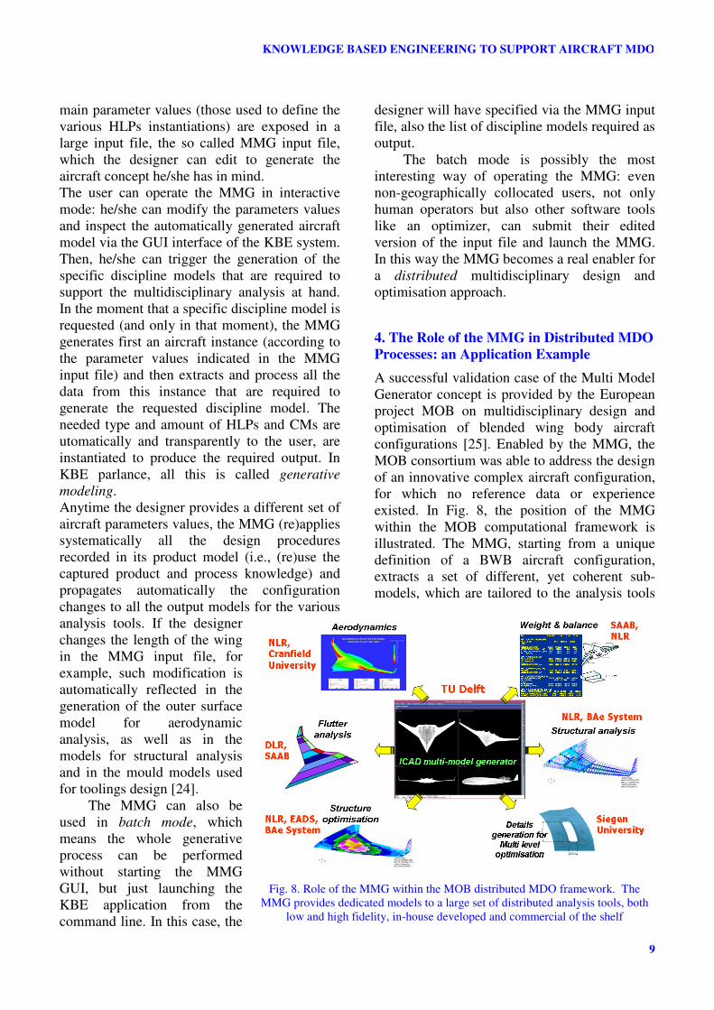
4. The Role of the MMG in Distributed MDO
Processes: an Application Example
A successful validation case of the Multi Model
Generator concept is provided by the European
project MOB on multidisciplinary design and
optimisation of blended wing body aircraft
configurations [25]. Enabled by the MMG, the
MOB consortium was able to address the design
of an innovative complex aircraft configuration,
for which no reference data or experience
existed. In Fig. 8, the position of the MMG
within the MOB computational framework is
illustrated. The MMG, starting from a unique
definition of a BWB aircraft configuration,
extracts a set of different, yet coherent sub-
models, which are tailored to the analysis tools
Fig. 8. Role of the MMG within the MOB distributed MDO framework. The
MMG provides dedicated models to a large set of distributed analysis tools, both
low and high fidelity, in-house developed and commercial of the shelf
G. LA ROCCA, M.J.L. VAN TOOREN
10
provided by a broad group of partners, both
from industry and academia. Among others, low
and high fidelity models for aerodynamic
analysis, 2-D planform models for aeroelastic
analysis, structural models for FEM analysis
and optimisation, fuel tanks and systems masses
distribution for weigh and balance assessment
are automatically generated by the MMG. The
MMG provides also the capability to focus on a
specific detail of the aircraft, a door cutout in
this case, and provides the base to apply a multi-
level analysis and optimisation strategy. Once
the MOB computational framework was in
place, more than 50 aircraft variants (including
topological variations) have been evaluated just
in a couple of days, totally hands off, making
use of high fidelity analysis tools (including
CFD and FE) running on a number of
computers distributed across the multinational
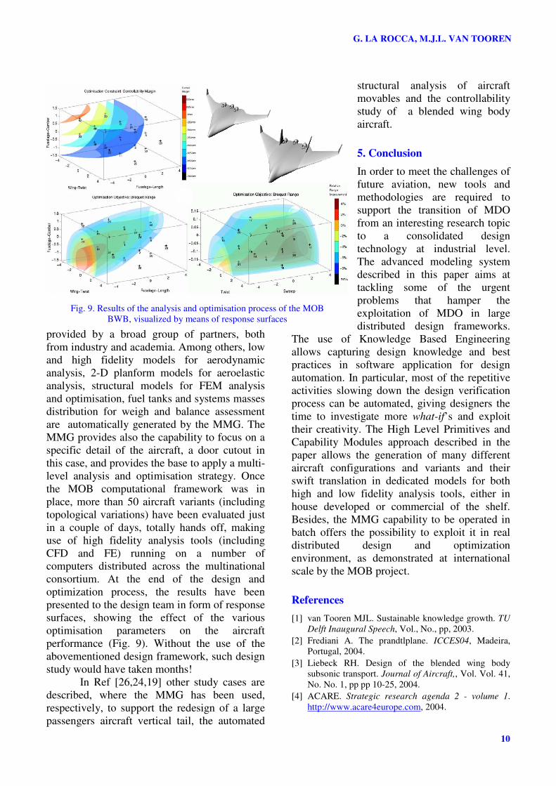
consortium. At the end of the design and
optimization process, the results have been
presented to the design team in form of response
surfaces, showing the effect of the various
optimisation parameters on the aircraft
performance (Fig. 9). Without the use of the
abovementioned design framework, such design
study would have taken months!
In Ref [26,24,19] other study cases are
described, where the MMG has been used,
respectively, to support the redesign of a large
passengers aircraft vertical tail, the automated
structural analysis of aircraft
movables and the controllability
study of a blended wing body
aircraft.
5. Conclusion
In order to meet the challenges of
future aviation, new tools and
methodologies are required to
support the transition of MDO
from an interesting research topic
to a consolidated design
technology at industrial level.
The advanced modeling system
described in this paper aims at
tackling some of the urgent
problems that hamper the
exploitation of MDO in large
distributed design frameworks.
The use of Knowledge Based Engineering
allows capturing design knowledge and best
practices in software application for design
automation. In particular, most of the repetitive
activities slowing down the design verification
process can be automated, giving designers the
time to investigate more what-if’s and exploit
their creativity. The High Level Primitives and
Capability Modules approach described in the
paper allows the generation of many different
aircraft configurations and variants and their
swift translation in dedicated models for both
high and low fidelity analysis tools, either in
house developed or commercial of the shelf.
Besides, the MMG capability to be operated in
batch offers the possibility to exploit it in real
distributed design and optimization
environment, as demonstrated at international
scale by the MOB project.
References
[1] van Tooren MJL. Sustainable knowledge growth. TU
Delft Inaugural Speech, Vol., No., pp, 2003.
[2] Frediani A. The prandtlplane. ICCES04, Madeira,
Portugal, 2004.
[3] Liebeck RH. Design of the blended wing body
subsonic transport. Journal of Aircraft,, Vol. Vol. 41,
No. No. 1, pp pp 10-25, 2004.
[4] ACARE. Strategic research agenda 2 - volume 1.
http://www.acare4europe.com, 2004.
Fig. 9. Results of the analysis and optimisation process of the MOB
BWB, visualized by means of response surfaces
11
KNOWLEDGE BASED ENGINEERING TO SUPPORT AIRCRAFT MDO
[5] de Weck O, Agte, J, Sobieszczanski-Sobiesk, J,
Arendsen, P, Morris, A and Spieck, M. State-of-the-
art and future trends in multidisciplinary design
optimization. 48th AIAA/ASME/ASCE/AHS/ASC
Structures, Structural Dynamics, and Materials
Conference, Honolulu, Hawaii, 2007.
[6] Schrage D, Beltracchi, T, Berke, L, Dodd, A,
Niedling, L and Sobieski, J. Aiaa technical committee
on multidisciplinary design optimization (mdo) -
white paper on current state of the art
http://endo.sandia.gov/AIAA_MDOTC/sponsored/aia
a_paper.html#appendixI, 1991.
[7] Bartholomew P. The role of mdo within aerospace
design and progress towards an mdo capability
through european collaboration. 7th
AIAA/USAF/NASA/ISSMO Symposium on
Multidisciplinary Analysis and Optimization, St.
Louis, MO, 1998.
[8] Belie R. Non-technical barriers to multidisciplinary
optimisation in the aerospace industry. 9th
AIAA/ISSMO Symposium of Multidisciplinary
Analysis and Optimisation, Atlanta, Georgia, AIAA-
2002-5439, 2002.
[9] Giesing JP and Barthelemy, JM. A summary of
industry mdo applications and needs. 7th
AIAA/USAF/NASA/ISSMO Symposium on
Multidisciplinary Analysis and Optimization, St.
Louis, MO, 1998.
[10] Cooper D and La Rocca, G Knowledge-based
techniques for developing engineering applications in
the 21st century, Belfast, Northern Ireland, 2007.
[11] Cooper S, Fan, I and Li, G Achieving competitive
advantage through knowledge based engineering - a
best practice guide, 2001.
[12] La Rocca G. Knowledge based engineering
techniques to support aircraft multidisciplinary
design, analyis and optimisation (phd dissertation to
be published). Delft University of Technology, 2008.
[13] La Rocca G and van Tooren, MJL. Enabling
distributed multi-disciplinary design of complex
products: A knowledge based engineering approach.
Journal of Design Research, Vol. 5, No. 3, pp 333-
352, 2007.
[14] Milton N. Knowledge technologies. Polimetrica,
2008.
[15] Mohaghegh M. Evolution of structures design
philosophy and criteria. 45th
AIAA/ASME/ASCE/AHS/ASC Structures, Structural
Dynamics & Materials Conference, Palm Springs,
California, 2004.
[16] Sully P. Modelling the world with objects. Prentice-
Hall, 1993.
[17] La Rocca G and van Tooren, MJL. A knowledge
based engineering approach to support automatic
generation of fe models in aircraft design. 45th AIAA
Aerospace Sciences Meeting and Exhibit, Reno, NV,
2007
[18] Qin N, Vavalle, A, Le Moigne, A, Laban, M, Hackett,
K and Weinerfelt, P. Aerodynamic studies for
blended wing body aircraft. 9th AIAA/ISSMO
Symposium on Multidisciplinary Analysis and
Optimisation, Atlanta, GA, 2002.
[19] Voskuijl M, La Rocca, G and Dircken, F.
Controllability of blended wing body aircraft. ICAS
2008, Anchorage, Alaska, 2008.
[20] Cerulli C, van Keulen, F and Rixen, DJ. Dynamic
reanalysis and component mode synthesis to improve
aircraft modeling for loads calculation. 48th
AIAA/ASME/ASCE/AHS/ASC Structures, Structural
Dynamics, and Materials Conference, Honolulu,
Hawaii, 2007.
[21] Laban M, Arendsen, P, Rouwhorst, WFJA and
Vankan, WJ. A computational design engine for
multidisciplinary optimisation with application to a
blended wing body configuration. 9th AIAA/ISSMO
Symposium on Multidisciplinary Analysis and
Optimisation, Atlanta, GA, 2002.
[22] Lisandrin P and van Tooren, MJL. High-order finite
elements reduced models for use in a flutter design
tool. Journal of Aircraft, Vol. vol.42, No. no.3, pp
748-754, 2005.
[23] Rumbaugh J, Blaha, M, Premerlani, W, Eddy, F and
Lorensen, W. Object-oriented modeling and design.
Prentice-Hall,, 1991.
[24] van der Laan A and van Tooren, MJL. Parametric
modeling of movables for structural analysis. Journal
of Aircraft, Vol. 42, No. 6, pp 1605-1613, 2005.
[25] Morris AJ, La Rocca, G, Arendsen, P, Laban, M,
Voss, R and Hönlinger, H. Mob - a european project
on multidisciplinary design optimisation. 24th ICAS
Congress, Yokohama, Japan, 2004.
[26] Cerulli C, Schut, EJ, Berends, JPTJ and van Tooren,
MJL. Tail optimization and redesign in a multi agent
task environment. 47th AIAA/ASME/ASCE/AHS/ASC
Structures, Structural Dynamics, and Materials
Conference, Newport, RI, USA, 2006
Copyright Statement
The authors confirm that they, and/or their company or
institution, hold copyright on all of the original material
included in their paper. They also confirm they have
obtained permission, from the copyright holder of any
third party material included in their paper, to publish it as
part of their paper. The authors grant full permission for
the publication and distribution of their paper as part of
the ICAS2008 proceedings or as individual off-prints
from the proceedings.


![Multidisciplinary optimization of a stiffened shell by ... · Multidisciplinary optimization of a stiffened shell by genetic algorithm ... ESDU [10] (Engi-neering Science Data Unit)](https://img.pdfslide.us/doc/110x75/5e8c3015c00854179364e697/multidisciplinary-optimization-of-a-stiffened-shell-by-multidisciplinary-optimization.jpg)