Embed Size (px)
Citation preview
Knoop Hardness on the (0001) Plane of 4H and 6H Silicon
Carbide (SiC) Single Crystals Fabricated by Physical Vapor
Transport
by Jeffrey J. Swab, James W. McCauley, Brady Butler, Daniel Snoha,
Donovan Harris, Andrew A. Wereszczak, and Mattison K. Ferber
ARL-TR-6910 May 2014
Approved for public release; distribution is unlimited.
NOTICES
Disclaimers
The findings in this report are not to be construed as an official Department of the Army position unless
so designated by other authorized documents.
Citation of manufacturer’s or trade names does not constitute an official endorsement or approval of the
use thereof.
Destroy this report when it is no longer needed. Do not return it to the originator.
Army Research Laboratory Aberdeen Proving Ground, MD 21005-5069
ARL-TR-6910 May 2014
Knoop Hardness on the (0001) Plane of 4H and 6H Silicon
Carbide (SiC) Single Crystals Fabricated by Physical Vapor
Transport
Jeffrey J. Swab, James W. McCauley, Brady Butler, Daniel Snoha, and
Donovan Harris Weapons and Materials Research Directorate, ARL
Andrew A. Wereszczak and Mattison K. Ferber Oak Ridge National Laboratory
Approved for public release; distribution is unlimited.
ii
REPORT DOCUMENTATION PAGE Form Approved OMB No. 0704-0188
Public reporting burden for this collection of information is estimated to average 1 hour per response, including the time for reviewing instructions, searching existing data sources, gathering and maintaining the data needed, and completing and reviewing the collection information. Send comments regarding this burden estimate or any other aspect of this collection of information, including suggestions for reducing the burden, to Department of Defense, Washington Headquarters Services, Directorate for Information Operations and Reports (0704-0188), 1215 Jefferson Davis Highway, Suite 1204, Arlington, VA 22202-4302. Respondents should be aware that notwithstanding any other provision of law, no person shall be subject to any penalty for failing to comply with a collection of information if it does not display a currently valid OMB control number.
PLEASE DO NOT RETURN YOUR FORM TO THE ABOVE ADDRESS.
1. REPORT DATE (DD-MM-YYYY)
May 2014
2. REPORT TYPE
Final
3. DATES COVERED (From - To)
October 2013–September 2013 4. TITLE AND SUBTITLE
Knoop Hardness on the (0001) Plane of 4H and 6H SiC Single Crystals Fabricated
by Physical Vapor Transport
5a. CONTRACT NUMBER
5b. GRANT NUMBER
5c. PROGRAM ELEMENT NUMBER
6. AUTHOR(S)
Jeffrey J. Swab, James W. McCauley, Brady Butler, Daniel Snoha, Donovan
Harris, Andrew A. Wereszczak,* and Mattison K. Ferber
*
5d. PROJECT NUMBER
5e. TASK NUMBER
5f. WORK UNIT NUMBER
7. PERFORMING ORGANIZATION NAME(S) AND ADDRESS(ES)
U.S. Army Research Laboratory
ATTN: RDRL-WMM-E
Aberdeen Proving Ground, MD 21005-5069
8. PERFORMING ORGANIZATION REPORT NUMBER
ARL-TR-6910
9. SPONSORING/MONITORING AGENCY NAME(S) AND ADDRESS(ES)
10. SPONSOR/MONITOR’S ACRONYM(S)
11. SPONSOR/MONITOR'S REPORT NUMBER(S)
12. DISTRIBUTION/AVAILABILITY STATEMENT
Approved for public release; distribution is unlimited.
13. SUPPLEMENTARY NOTES
*Oak Ridge National Laboratory, Oak Ridge, TN
14. ABSTRACT
The Knoop hardness of 4H and 6H single crystals of silicon carbide (SiC) was determined at room temperature. X-ray
diffraction techniques confirmed the crystal structure and orientation of each polytype verifying that both discs had the six-fold
symmetry expected for a hexagonal crystal and that the c-axis was oriented approximately perpendicular to disc faces. This
symmetry was confirmed by the Knoop hardness values on the (0001) plane of the 4H crystal, but the symmetry was not as
apparent in the 6H crystal, which may indicate that the c-axis was not as nearly aligned to the faces of the 6H as it was in the
4H crystal. The Knoop hardness was determined at 15° increments around the c-axis using 0.98 and 2.94 N indentation loads.
The average Knoop hardness on the (0001) plane at 0.98 N was approximately 30 GPa for both crystals with the average
dropping to around 24 GPa for the 6H crystal and 23 GPa for the 4H when the indentation load was increased to 2.94 N. The
difference between the maximum and minimum hardness values on the (0001) plane of both crystals at the 0.98 N indentation
load was approximately 2 GPa but the difference was significantly less at 2.94 N. 15. SUBJECT TERMS
silicon carbide, single crystal, Knoop hardness, physical vapor transport
16. SECURITY CLASSIFICATION OF: 17. LIMITATION OF ABSTRACT
UU
18. NUMBER OF PAGES
20
19a. NAME OF RESPONSIBLE PERSON
Jeffrey J. Swab a. REPORT
Unclassified
b. ABSTRACT
Unclassified
c. THIS PAGE
Unclassified
19b. TELEPHONE NUMBER (Include area code)
410-306-0753
Standard Form 298 (Rev. 8/98)
Prescribed by ANSI Std. Z39.18
iii
Contents
List of Figures iv
List of Tables iv
1. Introduction 1
2. Material Information 3
3. Experimental Procedure 4
4. Results and Discussion 5
5. Summary 10
6. References 11
Distribution List 13
iv
List of Figures
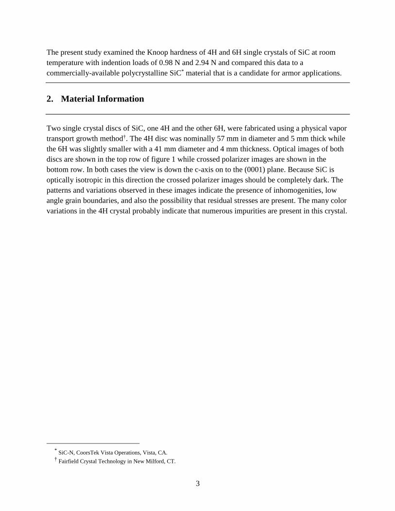
Figure 1. Optical and crossed polarizers images of the 4H and 6H SiC crystals. The top images are the optical images while the bottom images are from cross polarizers lighting. .....4
Figure 2. Schematic of the location of the Knoop indentation placement in the SiC crystals.........5
Figure 3. Plot of Knoop hardness as a function of the radial angle around the c-axis. Left plot is the 4H and the right the 6H. ...................................................................................................7
Figure 4. Images of the Knoop indents in the 4H SiC crystal using indentation loads of 0.98 N (top) and 2.94 N (bottom). The arrows highlight some of the minor cracking associated with these indentations. Red arrows highlight a possible lateral crack associated with a 0.98 N indent. White arrows show the short radial cracks that can come off the tips of the 2.94 N indents. ...........................................................................................................................7
Figure 5. Images of the Knoop indents in the 6H SiC crystal using indentation loads of 0.98 N (top) and 2.94 N (bottom). White arrows show the short radial cracks that can come off the tips of the 2.94 N indents. ....................................................................................................9
Figure 6. Load-Displacement curves from spherical indentation tests conducted at 20 N. ...........10
List of Tables
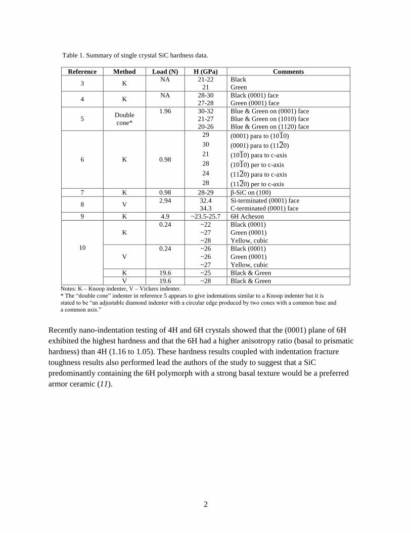
Table 1. Summary of single crystal SiC hardness data. ...................................................................2
Table 2. Knoop hardness data for 4H and 6H SiC single crystals and SiC-N. ................................8
1
1. Introduction
Silicon carbide (SiC) is an advanced ceramic that is widely used in a variety of applications such
as abrasives, heat exchanger tubes, body and vehicle armor, and in numerous electronic devices.
It has hundreds of polytypes that are based on the arrangement of successive layers of the SiC
tetrahedra unit cell. The cubic crystal structure is commonly referred to as the β-phase, while the
α-phase refers to polytypes with the hexagonal or rhombohedral crystal structure. The common
polytype in the β-phase is 3C. The 4H and 6H, both of which have a hexagaonal crystal structure,
and the 15R which is rhombohedral, are the most common polytypes in the α phase (1). As a
result, the hardness of polycrystalline SiC can vary within a bulk specimen since numerous
polytypes are typically present. Additionally the hardness should vary as a function of
crystallographic orientation as suggested by the significant difference in anisotropic elastic
constants (cij) (2), but hardness in the α phase should still exhibit hexagonal symmetry on the
(0001) plane.
The data available on the hardness of single crystals of SiC is summarized in table 1 (3–10).
Knoop hardness results from over 70 years ago by Peters and Knoop (3) and then Winchell (4)
are quite different and may be due to differences in the polytype examined, the indentation load
(which is not reported in either publication), or the level of impurities in the SiC*. Subsequent
work by Shaffer (6) on 6H crystals found that the hardest direction (hardness values approaching
30 GPa) was on the (0001) face when the long-axis of the Knoop indenter was parallel to (112̄0)
plane. The lowest hardness of 21 GPa was observed when indents were placed parallel to the
c-axis on the (101̄0) face. Further research by Shaffer (7) showed that the β-phase was not
significantly softer than the α-phase, however it did exhibit less hardness anisotropy. Sawyer et
al (9) reported that the hardness on the (0001) plane of 6H SiC varied between approximately
23.5 to 25.7 GPa as a function of orientation and attributed this anisotropy to dislocation slip.
Rendtel, et al (10) conducted Vickers and Knoop hardness measurements using 0.24 and 19.6 N
indentation loads. The Knoop hardness at a 0.24 N load was 22–27 GPa for the (0001) black and
green crystals, but 25 GPa for both crystals when an indentation load of 19.6 N was used. The
Vickers hardness for these crystals at these same loads was significantly less.
* The colors black, blue, green, and yellow observed in SiC and listed in table 1 are due to the presence of different
impurities.
2
Table 1. Summary of single crystal SiC hardness data.
Reference Method Load (N) H (GPa) Comments
3 K NA 21-22
21
Black
Green
4 K NA 28-30
27-28
Black (0001) face
Green (0001) face
5 Double
cone*
1.96 30-32
21-27
20-26
Blue & Green on (0001) face
Blue & Green on (1010) face
Blue & Green on (1120) face
6 K 0.98
29 (0001) para to (101̄0)
30 (0001) para to (112̄0)
21 (101̄0) para to c-axis
28 (101̄0) per to c-axis
24 (112̄0) para to c-axis
28 (112̄0) per to c-axis
7 K 0.98 28-29 β-SiC on (100)
8 V 2.94 32.4
34.3
Si-terminated (0001) face
C-terminated (0001) face
9 K 4.9 ~23.5-25.7 6H Acheson
10
K
0.24 ~22 Black (0001)
~27 Green (0001)
~28 Yellow, cubic
V
0.24 ~26 Black (0001)
~26 Green (0001)
~27 Yellow, cubic
K 19.6 ~25 Black & Green
V 19.6 ~28 Black & Green Notes: K – Knoop indenter, V – Vickers indenter.
* The “double cone” indenter in reference 5 appears to give indentations similar to a Knoop indenter but it is
stated to be “an adjustable diamond indenter with a circular edge produced by two cones with a common base and
a common axis.”
Recently nano-indentation testing of 4H and 6H crystals showed that the (0001) plane of 6H
exhibited the highest hardness and that the 6H had a higher anisotropy ratio (basal to prismatic
hardness) than 4H (1.16 to 1.05). These hardness results coupled with indentation fracture
toughness results also performed lead the authors of the study to suggest that a SiC
predominantly containing the 6H polymorph with a strong basal texture would be a preferred
armor ceramic (11).
3
The present study examined the Knoop hardness of 4H and 6H single crystals of SiC at room
temperature with indention loads of 0.98 N and 2.94 N and compared this data to a
commercially-available polycrystalline SiC* material that is a candidate for armor applications.
2. Material Information
Two single crystal discs of SiC, one 4H and the other 6H, were fabricated using a physical vapor
transport growth method†. The 4H disc was nominally 57 mm in diameter and 5 mm thick while
the 6H was slightly smaller with a 41 mm diameter and 4 mm thickness. Optical images of both
discs are shown in the top row of figure 1 while crossed polarizer images are shown in the
bottom row. In both cases the view is down the c-axis on to the (0001) plane. Because SiC is
optically isotropic in this direction the crossed polarizer images should be completely dark. The
patterns and variations observed in these images indicate the presence of inhomogenities, low
angle grain boundaries, and also the possibility that residual stresses are present. The many color
variations in the 4H crystal probably indicate that numerous impurities are present in this crystal.
* SiC-N, CoorsTek Vista Operations, Vista, CA. † Fairfield Crystal Technology in New Milford, CT.
4
Figure 1. Optical and crossed polarizers images of the 4H and 6H SiC crystals. The top images are the optical
images while the bottom images are from cross polarizers lighting.
3. Experimental Procedure
Crystallographic Orientation: the polymorphs of each disc were confirmed using X-ray
diffraction with φ = 0-360°, ψ = 0-87° in 0.5° and 3° increments respectively. The 2θ value was
fixed for the crystal plane of interest. The orientation was identified by analyzing orientations
where this specific Bragg condition was satisfied. This analysis technique indicated
5
the presence of a specific polymorph, but it did not eliminate the possibility of multiple
polymorphs being present within each disc.
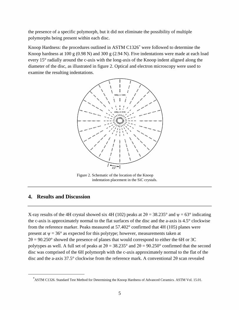
Knoop Hardness: the procedures outlined in ASTM C1326* were followed to determine the
Knoop hardness at 100 g (0.98 N) and 300 g (2.94 N). Five indentations were made at each load
every 15° radially around the c-axis with the long-axis of the Knoop indent aligned along the
diameter of the disc, as illustrated in figure 2. Optical and electron microscopy were used to
examine the resulting indentations.
Figure 2. Schematic of the location of the Knoop
indentation placement in the SiC crystals.
4. Results and Discussion
X-ray results of the 4H crystal showed six 4H (102) peaks at 2θ = 38.235° and ψ = 63° indicating
the c-axis is approximately normal to the flat surfaces of the disc and the a-axis is 4.5° clockwise
from the reference marker. Peaks measured at 57.402° confirmed that 4H (105) planes were
present at ψ = 36° as expected for this polytype; however, measurements taken at
2θ = 90.250° showed the presence of planes that would correspond to either the 6H or 3C
polytypes as well. A full set of peaks at 2θ = 38.235° and 2θ = 90.250° confirmed that the second
disc was comprised of the 6H polymorph with the c-axis approximately normal to the flat of the
disc and the a-axis 37.5° clockwise from the reference mark. A conventional 2θ scan revealed
*ASTM C1326. Standard Test Method for Determining the Knoop Hardness of Advanced Ceramics. ASTM Vol. 15.01.
6
faint traces of the forbidden reflections corresponding to planes normal to the c-axis and
provided further confirmation that the 4H and 6H polytypes were indeed present in each
respective sample.
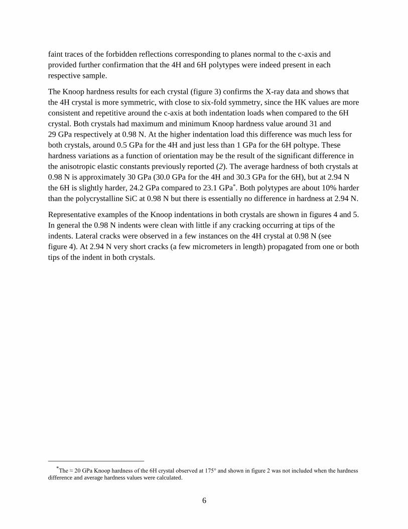
The Knoop hardness results for each crystal (figure 3) confirms the X-ray data and shows that
the 4H crystal is more symmetric, with close to six-fold symmetry, since the HK values are more
consistent and repetitive around the c-axis at both indentation loads when compared to the 6H
crystal. Both crystals had maximum and minimum Knoop hardness value around 31 and
29 GPa respectively at 0.98 N. At the higher indentation load this difference was much less for
both crystals, around 0.5 GPa for the 4H and just less than 1 GPa for the 6H poltype. These
hardness variations as a function of orientation may be the result of the significant difference in
the anisotropic elastic constants previously reported (2). The average hardness of both crystals at
0.98 N is approximately 30 GPa (30.0 GPa for the 4H and 30.3 GPa for the 6H), but at 2.94 N
the 6H is slightly harder, 24.2 GPa compared to 23.1 GPa*. Both polytypes are about 10% harder
than the polycrystalline SiC at 0.98 N but there is essentially no difference in hardness at 2.94 N.
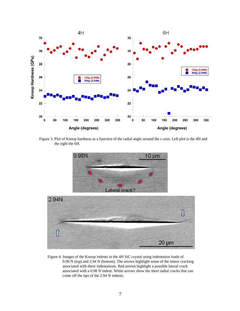
Representative examples of the Knoop indentations in both crystals are shown in figures 4 and 5.
In general the 0.98 N indents were clean with little if any cracking occurring at tips of the
indents. Lateral cracks were observed in a few instances on the 4H crystal at 0.98 N (see
figure 4). At 2.94 N very short cracks (a few micrometers in length) propagated from one or both
tips of the indent in both crystals.
*The ≈ 20 GPa Knoop hardness of the 6H crystal observed at 175° and shown in figure 2 was not included when the hardness
difference and average hardness values were calculated.
7
Figure 3. Plot of Knoop hardness as a function of the radial angle around the c-axis. Left plot is the 4H and
the right the 6H.
Figure 4. Images of the Knoop indents in the 4H SiC crystal using indentation loads of
0.98 N (top) and 2.94 N (bottom). The arrows highlight some of the minor cracking
associated with these indentations. Red arrows highlight a possible lateral crack
associated with a 0.98 N indent. White arrows show the short radial cracks that can
come off the tips of the 2.94 N indents.

8
Since the 4H disc was more symmetric about the c-axis and larger in size additional Knoop
hardness measurements were made at 0.49, 7.85 and 19.61 N. Table 2 summarizes the average
Knoop hardness values for over 100 indents made at each indentation load. There is a
pronounced decrease in the Knoop hardness of the 4H crystal with increasing load indicative of
the well documented indentation size effect that has been observed in numerous polycrystalline
and single crystal ceramic materials (12–15).
Table 2. Knoop hardness data for 4H and 6H SiC single crystals and SiC-N.
Load
(N)
Ave HK
(GPa) STDEV
Ave HK
(GPa) STDEV
Ave HK
(GPa) STDEV
0.49 39.5 2.2 NA NA NA NA
0.98 30 1.0 30.3 1.2 26.2 1.0
2.94 23.1 0.5 24.2 1.1 24.2 1.3
7.85 22.4 0.9 NA NA NA NA
19.61 19.5 0.7 NA NA 20.5 0.2
4H 6H SiC-N
The Knoop hardness values at the 0.98 N indentation load are in excellent agreement with the
earlier values given by Shaffer (6) for the (0001) plane. However, the value generated by
Rendtlel, et al. (9) at 19.6 N is approximately 20% higher and their values at 0.24 N do not fit the
hardness-load trend for the 4H crystal shown in table 2. The study showed that the Knoop
hardness for single crystals as well as several polycrystalline SiC materials increased when the
indentation load was increased from 0.24 to 0.48 N, then the hardness gradually dropped as the
load was increased beyond 0.48 N. These discrepancies may be due to differences in the
polytypes examined and/or impurity levels in the crystals.
9
Figure 5. Images of the Knoop indents in the 6H SiC crystal using indentation loads of 0.98 N (top)
and 2.94 N (bottom). White arrows show the short radial cracks that can come off the tips of
the 2.94 N indents.
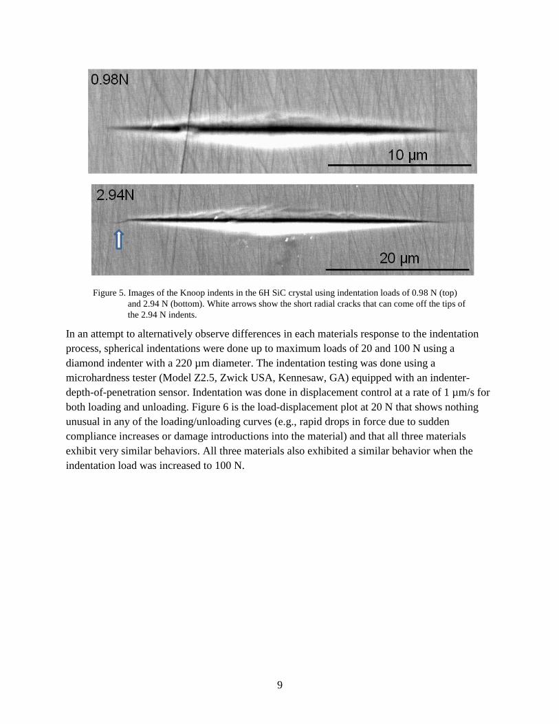
In an attempt to alternatively observe differences in each materials response to the indentation
process, spherical indentations were done up to maximum loads of 20 and 100 N using a
diamond indenter with a 220 µm diameter. The indentation testing was done using a
microhardness tester (Model Z2.5, Zwick USA, Kennesaw, GA) equipped with an indenter-
depth-of-penetration sensor. Indentation was done in displacement control at a rate of 1 µm/s for
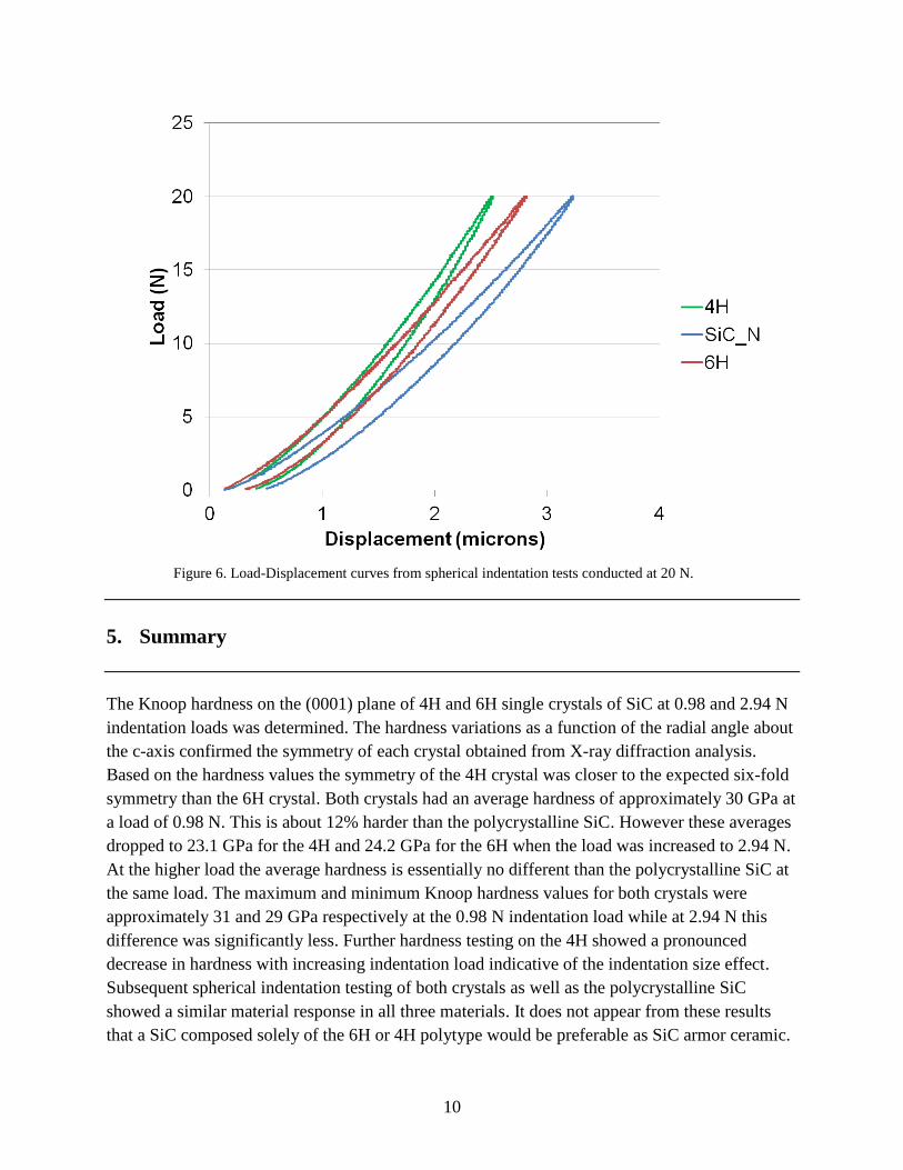
both loading and unloading. Figure 6 is the load-displacement plot at 20 N that shows nothing
unusual in any of the loading/unloading curves (e.g., rapid drops in force due to sudden
compliance increases or damage introductions into the material) and that all three materials
exhibit very similar behaviors. All three materials also exhibited a similar behavior when the
indentation load was increased to 100 N.
10
Figure 6. Load-Displacement curves from spherical indentation tests conducted at 20 N.
5. Summary
The Knoop hardness on the (0001) plane of 4H and 6H single crystals of SiC at 0.98 and 2.94 N
indentation loads was determined. The hardness variations as a function of the radial angle about
the c-axis confirmed the symmetry of each crystal obtained from X-ray diffraction analysis.
Based on the hardness values the symmetry of the 4H crystal was closer to the expected six-fold
symmetry than the 6H crystal. Both crystals had an average hardness of approximately 30 GPa at
a load of 0.98 N. This is about 12% harder than the polycrystalline SiC. However these averages
dropped to 23.1 GPa for the 4H and 24.2 GPa for the 6H when the load was increased to 2.94 N.
At the higher load the average hardness is essentially no different than the polycrystalline SiC at
the same load. The maximum and minimum Knoop hardness values for both crystals were
approximately 31 and 29 GPa respectively at the 0.98 N indentation load while at 2.94 N this
difference was significantly less. Further hardness testing on the 4H showed a pronounced
decrease in hardness with increasing indentation load indicative of the indentation size effect.
Subsequent spherical indentation testing of both crystals as well as the polycrystalline SiC
showed a similar material response in all three materials. It does not appear from these results
that a SiC composed solely of the 6H or 4H polytype would be preferable as SiC armor ceramic.
11
6. References
1. Shaffer, P. T. B. A Review of the Structure of Silicon Carbide. Acta Crystallographica, B25
1969, 477–488.
2. Li, H.; Bradt, R. C. The Single Crystal Elastic Constants of Hexagonal SiC to 1000 °C.
Int. J. High Tech. Ceram. 1988, 4, 1–10.
3. Peters, C. G.; Knoop, F. Metals in Thin Layers – Their Microhardness. Metals and Alloys
September 1940, 292–297.
4. Winchell, H. The Knoop Microhardness Tester as a Mineralogical Tool. Am. Mineralogist
1945, 30 (9–10) 583–595.
5. Stern, W. Directional Hardness Differences in Silicon Carbide Crystals. Ind. Diamond Rev.
1951, 11, 237–239.
6. Shaffer, P.T.B.. Effect of Crystal Orientation on Hardness of Silicon Carbide. J. Am. Ceram.
Soc. 1964, 47 (9), 466.
7. Shaffer, P. T. B. Effect of Crystal Orientation on Hardness of Beta Silicon Carbide. J. Am.
Ceram. Soc. 1965, 48 (11), 601–02.
8. Ning, X. J.; Huvey, N.; Pirouz, P. Dislocation Cores and Hardness Polarity of 4H-SiC.
J. Am. Ceram. Soc. 1997, 80 (7), 1645–52.
9. Sawyer, G. R.; Sargent, P. M.; Page, T. F. Microhardness Anisotropy of Silicon Carbide.
J. Mat. Sci. 1980, 15, 1001–1013.
10. Rendtel, A.; Moessner, B. Schwetz, K. A. Hardness and Hardness Determination in Silicon
Carbide Materials. Ceram. Eng. Sci. Proc. 2005, 26 (7) 161–168.
11. K.E. Prasad and K.T. Ramesh, “Anisotropy in Hardness in Hexagonal SiC Single Crystals,”
presented at the 2013 MACH Conference, Annapolis, MD, April 2013.
12. Swab, J .J. Recommendations for Determining the Hardness of Armor Ceramics. Int. J. Appl.
Ceram. Technol. 2004, 1 (3), 219–225.
13. Li, H.; Bradt, R. C. The Microhardness Indentation Size-Load Effect (ISE) in Hard Ceramic
Materials. J. Hard Mat. 1992, 3 (3–4), 403–419.
12
14. Li, H.; Bradt, R. C. The Indentation Load/Size Effect in Rutile and Cassiterite Single
Crystals. J. Mat. Sci. 1993, 28, 917–916.
15. Han, Y. H.; Li, H.; Wong, T. Y.; Bradt, R. C. Knoop Microhardness Anisotropy of Single-
Crystal Aragonite. J. Am. Ceram. Soc. 1991, 74 (12), 3129–3132.
NO. OF NO. OF
COPIES ORGANIZATION COPIES ORGANIZATION
13
1 DEFENSE TECHNICAL
(PDF) INFORMATION CTR
DTIC OCA
2 DIRECTOR
(PDF) US ARMY RESEARCH LAB
RDRL CIO LL
IMAL HRA MAIL & RECORDS MGMT
1 GOVT PRINTG OFC
(PDF) A MALHOTRA
2 RUTGERS UNIVERSITY
(PDF) R HABER
V DOMNICH
2 JOHNS HOPKINS UNIVERSITY
(PDF) KT RAMESH
E PRASAD
1 NATIONAL INS OF STAND & TECH
(PDF) G QUINN
3 CERADYNE
(PDF) M NORMANDIA
Z NAWAZ
B MIKIJELIJ
2 COORSTEK
(PDF) D ASKIN
R PALIKA
2 OAK RIDGE NAT LAB
(PDF) A WERESZCZAK
M FERBER
24 DIR USARL
(PDF) RDRL WM
J MCCAULEY
RDRL WMM E
J ADAMS
K BEHLER
M BRATCHER
C BRENNAN
J CAMPBELL
M GOLT
D HARRIS
S KILCZEWSKI
J LASALVIA
P PATEL
R PAVLACKA
J SINGH
J SWAB
E WARNER
J WRIGHT
RDRL WMM F
B BUTLER
H MAUPIN
RDRL WMP B
S SATAPATHY
RDRL WMP C
D CASEM
B LEAVY
RDRL WMP E
S BARTUS
E HORWATH
T JONES

14
INTENTIONALLY LEFT BLANK.