Embed Size (px)
Citation preview


Ct
Knock-Down
Workbench~1I- .'11~'" -
~. ..~ ..~. ~~ot¥\I\'
~
~
~...=:';,;.;;-
~
I
. ,f=tiJ'I~
"
1..1riJ,.tI'uIi
Ii
tr. ~
~
~
f~,J.11:1>1.!I
-- ,,"'" ~'f ~ t,.. ,
'"
C', .. .,...
Turn a single sheet of Plywoodand a few Pieces of hardware intoa portable workbench that "knocks
down" for compact storage.
H OJSetup.It only takes a minute to set up the workbench. Afterunlatching the top and setting it aside, remove the stretchersand flip up the sides, as shown in photo :4.' Toprovide rigid
16
A bench in a box. No, ifs not a new magic act Ifs what
one of the guys calls my new knock-down workbench. ~When you think about it, ifs a fittingdescription. v,'
Thafs because the bench provides a solid, stableworksur- j
face like you'd expect from a bench. (There's even a tool tray ,underneath.) Then, once a job is completed, the bench can be
I"knocked down" and stored in a
compact box that you carry likea suitcase. (See photo at right)
The best thing about thisknock-down design is it makesit easy to take the bench out tothe driveway or back yard, or toamend's house to help on apro-ject No matter where you'reworking, setting up the benchonlytakes a minute.
Setup - To do this, start byunlatching the lid on the boxand setting it aside. (The liddoublesasthe top of the work-bench.) Then simply removethe two stretchers and flip upthe sides of the bench, as shown in photo A below.
The sidesare hinged to the base, soyou'llneed to "spring"them apart a bit to fit the stretchers between them (photo B).These stretchers hook securely into the sides with an ordi-
nary set of bed rail fasteners. Then just set the top down over ~the sides and pull it toward you to lock it in place (photo C).
Clamping Options - Once the bench is set up, there arethree different ways to clamp a workpiece to the benchtop.That explains the holes and slots in the top as well as thenotches in the top ofthe stretchers. Note: For a closer look atthe different clamping options, turn to page 23.
Plywood - Just one more note. You won't need a lot ofmaterial to build this bench. The entire project is made froma single sheet of %"plywood. (1used pine plywood.)
1m rio" ~,,'> Ii'roci:glsupport for the top of the bench, the stretchers hook into the (sides (Photo B). Then just fit the top down over the sides ofthe bench and pull it toward you to "lock" it in place (Photo C).
ShopNotes No. 52
}
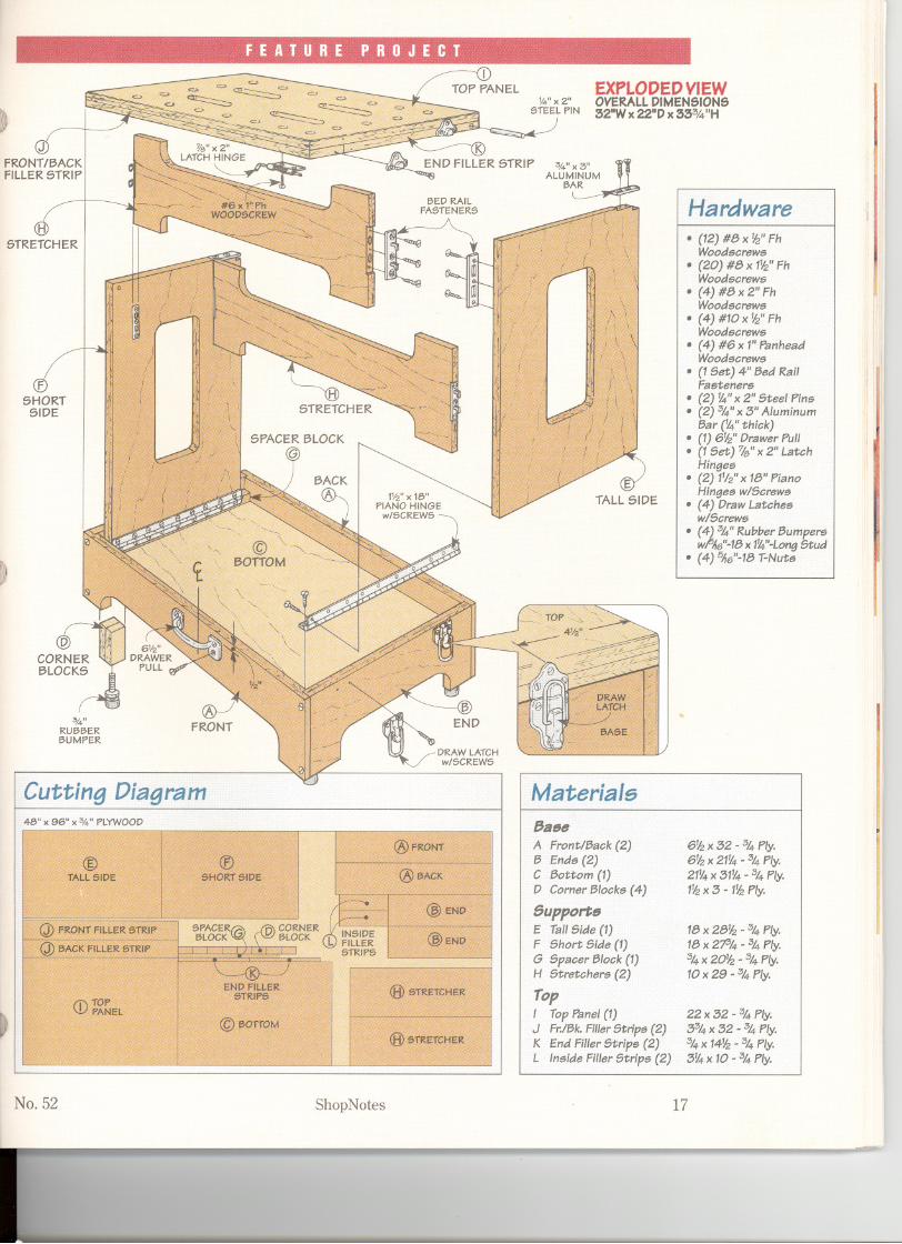
EXPLODEDVIEWOVERALLDIMENSIONS32"Wx22"Dx 33%"H)
tlSTRETCHER
ESHORT
SIDE
~
%"RUBBERBUMPER
@FRONT
Hardware1.11.(12) #8x~" Fh
Wood$crew$.(20) #8 x 1~"FhWood$crew$.(4) #8 x 2" FhWood$crewe.(4) #10 x~" FhWood$crew$
. (4) #6 x 1"~nheadWood$crew$.(1Set) 4" Bed RailFa$tener$.(2)~" x 2" Steel Pin$.(2) %-"x 5" AluminumBar ('l'4"thick).(1) 6~" DrawerPul1.(1 Set) ~"x 2" LatchHinge$.(2) 11fz"x 18" PianoHinge$ w/Screw$.(4) DrawLatcheew/Screw$.(4) %-"Rubber Bumper$W,PA6"-18 x 1'4"-Long Stud.(4) 5,16"-18T-Nute
"'I'I!I
1.:
1"I
11I
I~
Cutting Diagram Materials48" x 96" x 3",' PLYWOOD 8as8
A Front/Back (2)B End$ (2)CBottom (1)D Corner Block$ (4)
SupportsE TallSide (1)F Short Side (1)G Spacer Block (1)H Stretcher$ (2)
TopI TopPanel(1)J Fr./Bk.FillerStripe (2)K End FillerStrip$ (2)L In6ide FillerStrip$(2)
~
6'l'2 x 52 -%- Ply.
6~ x 21~ - %- Ply.
21V4 x 51V4 - %- Ply.
1~ x 5 - 1~ Ply.
18 x 28~ - ,% Ply.18 x 21% - %- Ply.%-x 20~ - %- Ply.10 x 29 - %-Ply.
22 x 52 - %- Ply.
5%- x 52 - %- Ply.
%- x 14~ - %- Ply.5'l'4 x 10 - %- Ply.
No.52 ShopNotes 17

.-
BaseI began work by making the baseofthe bench. As you can see in Figure1,it's a shallowbox with a large "foot-print" that helps the bench resist tip-ping. The base provides a handycompartment for tools while you'reworking. And when you "knockdown" the bench for storage, thebase holds the sides and stretchers.
Frame - The base starts out as aplywood frame that's made up of afront/back (A) and two entk (B). Tostrengthen the base (and help alignthe pieces duringassembly),the frontand back are rabbeted at each end.
An easy way to cut these rabbetsis to use a dado blade mounted in thetable saw.As you can see in Figures2 and 2a,part ofthe blade is "buried"in an auxiliary fence that's attachedto the rip fence with carpet tape.
The fence is positioned so theblade will cut the shoulder of therabbet. The only problem is the frontand back pieces are fairly narrow,too narrow to ride against the fencewithout twisting. To prevent that, Iattached a long fence to the mitergauge and used it to guide the work-piece through the blade.
Cut Grooves - In addition to therabbets, there's a groove in theinside face of each piece that holdsthe bottom of the base. The locationof this groove determines the depth
18
... -
a.
TOPVIEW
of the storage compartment in thebase. I wanted to make sure the com-partment was deep enough to holdthe sides and stretchers (and stillbeable to fasten the top on the base).
So after adjusting the width of thedado blade to match the thickness ofthe plywood bottom, I set the ripfence 3%" away from the outside ofthe blade (Figures 3 and 3a) .Runningthe bottomedge of each piece against
ShopNotes
~-
"
\j/1
NOTE:ALLPARTSARE MADEFROM3,t,"PLYWOOD
the fence will produce a groove that's
2%" down from the top edge. This ~provides enough room for the sidesand stretchers plus a littleextra.
Notches - After completing thegrooves, I cut a long notch in thebottom edge of each piece (Figures4a and 4b). These notches providesome "toeroom" so I can work at thebench without kicking the base. Asabre saw (or band saw) is all that's
CiJ)Y NOTE: RI.INY~-# BO1TOM EDGE
OF ALL FRAME?/' PIECES AGAINST
GROOVE RIP FENCE
{)

needed to cut the notches to rough
(~I shape. And a drum sander chuckedin the drill press makes quick workof removing the rest of the material.
But a drum sander can create ascalloped edge if you're not careful.To prevent that, I used a long,straightscrap piece as a fence (Figure 4).With the "feet" of theworkpiece riding againstthe fence, it's easy tosand a straight edge.
To sand the entire thickness ofthe edge, youll need to attach anauxiliary table to the drill press andcut a hole in it to accept the drumsander. Then, after notching thefence to fit around the drum sander,position it to sand to the desireddepth and clamp the fence in place.
Now turn on the drill press, andpush the workpiece into the drumsander until it contacts the fence.The idea is to start at the rightend ofthe notch, then slowlyfeed the work-piece from left to right to sand the
. edges smooth.,it Bottom - Before assembling the
base, there's one more thing to do.That's to cut the plywood bottom (C)to fit Then just glue and screw thebase together. I also "eased" all ofthe edges with a sanding block tokeep them from splintering whenthey get bumped or knocked around.
Corner Blocks - Allthat's left tocomplete the base is to add four
a. NOTCH DETAIL
NOTE: FEED WORKPIECEFROM LEFT TO RIGHT
b. NOTCH DETAIL
thick corner blocks (D) . Theseblocks "beef up" the corners of thebase to hold a set ofrubber bumpersthat are added later (Figure 1).
Each corner block is made up oftwo pieces of %"plywood. To avoidworking with small pieces, I gluedup two long strips of plywood first(Figure 5). Then it's just a matter ofcutting each corner block to length.
Here again, a fence attached to themiter gauge provides support for theblank. But this time, to cut eachblock to the same length, I clampeda
scrap piece of wood to the rip fenceand used it as a stop. The idea is toset the fence so that when you buttthe end of the blank against the stop,itwillproduce a 3"-longcorner block.
Rubber Bumpers - Aftercuttingall the corner blocks, the next step isto add a set of four rubber bumpers.(We've shown two in the margin.)These bumpers thread intoT-nutsthatfit into a hole drilled in each cornerblock (Figures 6and 6a).Aftergluingthe blocks in place, simplytap in theT-nuts and install the bumpers.
No. 52 ShopNotes
! Hard rubber
bumpers thread intothe base of the
bench to keep itfrom sliding aroundand to preventdamage to afinished floor. (Seepage 31 for sources.)
19

,
fEATURE PROJECT
SupportsThis workbench is designed with asimple system of interlocking partsthat provide solid support for thetop. As you can see in Figure 7, itconsists of two hinged sidescon-nected by a pair of stretchers.
To prevent the bench fromracking, the connection between thesides and stretchers must be rigidand strong. At the same time, Iwanted a quick and easy way to takethem apart
Bed Rail Fasteners - The solu-tion is a mechanical fastener like thetype used to hold the parts of a bedtogether. (Seephotoat left.)One partof the fastener (attached to the endof the stretcher) has two hooks thatfit into slots in the other part(mounted to the sides). This "locks"the parts together, yet still allowsthem to be quicklydisassembled.
Sides - I started by making thetwo sides of the bench. Both sidesare the same width (18").And they~pwrtobethesamekngth.&tthat's not the case. To allow bothsides to fold flat inside the base, thetall side (E) is %" longerthantheshort side (F), as shown in Figure 8.
Aside from the difference inlength, the sides are identical. Toreduce the weight of the bench, I cuta large opening in each side. Also,
. A two-piece bedrail fastener creates
a strong, rigidconnection that's
quick and easyto take apart. (See
page 31 for sources.)
273/4"
20
there's a short, metal bar on theupper back corner of each side that'sused to secure the top to the bench.
Bars - The two metal bars areeasy to make. I bought a %"-thickaluminum bar at a home center andused a hack saw to cut each one tolength. Then I drilled a couple ofcountersunk shank holes in eachpiece for mounting screws.
Before attaching the bars, youll
SLOTTEDBED RAIL
FASTENER
ShopNotes
QA~
b.
need to cut a "stairstep" notch in the
corner of each side. The upper part ...of this notch is sized to fit the bar VJII(Figure Sa).When you screw the barin place, it forms a lip over the lowerpart of the notch. This lip captures apin that's installed later in the top.
Cut Mortises - The next step isto cut the mortises that hold theslottedpart of the bed rail fasteners.As you can see in Figure 8a, the ideais to cut a two-tieredmortise. Awide,shallow mortise is sized to acceptthe fastener, and two narrow, deepmortises provide clearance for thehooks on the otherpart ofthe fastener.
An easy way to make the shallowmortises is to use a drill press and aForstner bit (Figure 9). A carefullayout will ensure that the upperends of the mortises align.As for thedistance of the mortises in from theedge, I clamped a fence to the drillpress tableand used itto positioneachworkpiece. Now it's just a matter ofdrilling a series of overlappingholes
and paring awaythe remainingwaste A.
..
with a chisel (Figure 9a). VOnce the fastener fits neatly in the
mortise, you can use it to layout thelocation of the two deepmortises
No. 52
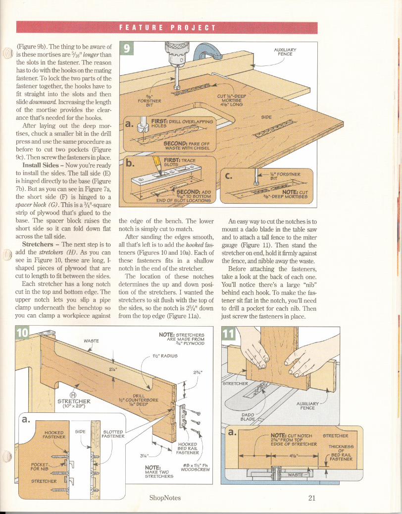
(Figure 9b). The thing to be aware ofis these mortises are 5116"longerthanthe slots in the fastener. The reasonhas to dowiththe hooksonthe matingfastener. To lock the two parts ofthefastener together, the hooks have tofit straight into the slots and thenslide downward.Increasingthe lengthof the mortise provides the clear-ance thafs needed for the hooks.
After laying out the deep mor-tises, chuck a smaller bit in the drillpress and use the same procedure asbefore to cut two pockets (Figure9c).Then screwthe fastenersinplace.
Install Sides - Nowyou're readyto install the sides. The tall side (E)is hinged directly to the base (Figure7b). But as you can see in Figure 7a,the short side (F) is hinged to aspacerblock (G). This is a %"-squarestrip of plywood thafs glued to thebase. The spacer block raises theshort side so it can fold down flatacross the tall side.
Stretchers - The next step is to
ift1 add the stretchers (H). As you can'J;I see in Figure 10, these are long, I-
shaped pieces of plywood that arecut to length to fitbetween the sides.
Each stretcher has a long notchcut in the top and bottom edge. Theupper notch lets you slip a pipeclamp underneath the benchtop soyou can clamp a workpiece against
a.
-
the edge of the bench. The lowernotch is simplycut to match.
After sanding the edges smooth,allthafs leftis to add the hookedfas-teners (Figures 10and lOa). Each ofthese fasteners fits in a shallownotch in the end of the stretcher.
The location of these notchesdetermines the up and down posi-tion of the stretchers. I wanted thestretchers to sit flush with the top ofthe sides, so the notch is 2%" downfrom the top edge (Figure 11a).
NOTE: STRETCHERSARE MADE FROM
54" PLYWOOD
IV2" RADIUS
J
NOTE:MAKE TWOSTRETCHERS
HOOK
~D
BED RAIL"5"""
#8x 1%"FhWOODSCREW
ShopNotes
Aneasywayto cut the notches is tomount a dado blade in the table sawand to attach a tall fence to the mitergauge (Figure 11). Then stand thestretcher on end, holdit:firmlyagainstthe fence,and nibbleawaythe waste.
Before attaching the fasteners,take a look at the back of each one.You11notice there's a large "nib"behind each hook. To make the fas-tener sit flat in the notch, you11needto drill a pocket for each nib. Thenjust screw the fasteners in place.
Ihi'II,,f~,"rip
j
J

~-
Top €d)),,:<1~r,
The top ofthe workbench that'sshown in Figure 12 has twomain jobs. It creates a solidworksurface. Plus it serves as alid for the base when you knockdown the bench for storage
But the handiest thing aboutthis benchtop is it providesthree different ways to clamp aworkpiece to the bench. (Referto the photos on page 23.)
Built-Up Top - To increasethe thickness of the top, it's"built up" from two layers of314"plywood. The upper layeris formed by a top panel (l)that's sized to fit flush with thebase (Figure 13). And thelower layer is made up of sev-eral smaller filler strips.
Filler Strips - These strips createa long,narrow recess underneath thetop which fits down over the sides ofthe bench. Plus they provide thethickness that's needed to hold a setof bench dogs. (For more about thebench dogs I used, turn to page 31.)
The front and backfiller strips aJare simplycut to match the length ofthe top panel. To fit over the sides of
TOP
the bench, you'llneed to cut a notchnear each end of these strips. Thenjust glue them in place.
Next, I added two narrow endfiller strips (K.). They're ripped towidth so when they're flush with theoutside edge of the top, they alignwith the notch in the front/backstrips. As for length, it's just a matterof cutting them to fit the opening.
After gluing on the end strips, Iadded two insidefiller strips (1). Toprovide clearance for the stretchers,these strips are shorter than the endstrips. Here again, the strips arealigned flush with the notch and
then glued in place.Slots for Clamps - With the filler
strips in place, the next step is to cutfour slots in the top. Each slot formsan opening for a bar clamp that letsyou clamp work near the middle ofthe benchtop. A quick way to cuteach slot is to drill a small starterhole and then remove the rest ofthewaste with a sabre saw (Figure 14).
Bench Dog Holes - In additionti»to the slots, I drilled a number ofholes in the top to hold the benchdogs. Since the top is quite large, Iclamped an auxiliarytable to my drillpress to support it (Figure 15). It's
! A simple two-partsystem is used to
fasten the top to thebench. Metal pins inthe top fit under the
aluminum bars on
the sides (upperphoto). And spring-loaded latches lock
the top in place(lower photo).
NOTE:BOTTOMSIDE NOTE: ALL PARTSARESHOW
~,N
""".",.,..."",."".,..."."..".".,"".."",."",
'
,',
'
.,
'
,
'
,
"
',""
L MADEFROM34"PLYWOOD,,';cL'C..;, INSIDE FILLER
R)"";""""""
~",,,,,,, STRIP
I "
".
' (3W' x 10")~ ."~' BACK FILLER
STRIP(:33/.:."x 32")
'J
8OTTOM VIEW
3/Ll=G
I(
13;'6"
No. 5222 ShopNotes
also a good idea to clamp a fence tothe table to make sure the holes arelocated the same distance in from theedge.Then layout and drillthe holes.
Locking System - At this point,the top is almost complete. Butbefore setting it on the bench, Iadded a simple, two-part system that"locks"it securely in place.
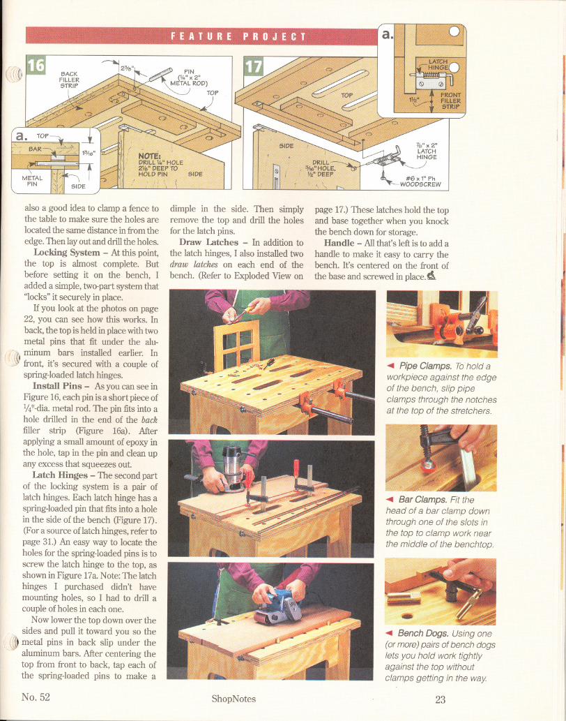
If you look at the photos on page22, you can see how this works. Inback, the top is held in placewithtwometal pins that fit under the alu-
1,ft!minum bars installed earlier. In~ front, it's secured with a couple of
spring-loaded latch hinges.Install Pins - As you can see in
Figure 16,each pin is a short piece of%"-dia.metal rod. The pin fits into ahole drilled in the end of the backfiller strip (Figure 16a). Afterapplying a small amount of epoxy inthe hole, tap in the pin and clean upany excess that squeezes out.
Latch Hinges - The second partof the locking system is a pair oflatch hinges. Each latch hinge has aspring-loadedpin that fits into a holein the side of the bench (Figure 17).(For a source oflatch hinges, refer topage 31.) An easy way to locate theholes for the spring-loaded pins is toscrew the latch hinge to the top, asshown in Figure 17a. Note:The latchhinges I purchased didn't havemounting holes, so I had to drill acouple of holes in each one.
Now lower the top down over thesides and pull it toward you so the
.~ metal pins in back slip under the, aluminumbars.Aftercenteringthe
top from front to back, tap each ofthe spring-loaded pins to make a
No. 52
dimple in the side. Then simplyremove the top and drill the holesfor the latch pins.
Draw Latches - In addition tothe latch hinges, I also installed twodraw latches on each end of thebench. (Refer to Exploded View on
#6 x 1"PhWOOD5CREW
~
page 17.)These latches hold the topand base together when you knockthe bench down for storage.
Handle - Allthat's left is to add ahandle to make it easy to carry thebench. It's centered on the front ofthe base and screwed in place. 4
ShopNotes
I I~
Pipe Clamps. Tohold aworkpiece against the edgeof the bench, slip pipeclamps through the notchesat the top of the stretchers.
I
IJ
II~
Bar Clamps. Fit the
head of a bar clamp downthrough one of the slots inthe top to clamp work near
the middle of the benchtop.
Bench Dogs. Using one(or more) pairs of bench dogslets you hold work tightlyagainst the top withoutclamps getting in the way
23