Embed Size (px)
Citation preview

KM-RingerDC Feed and Ring Power Supply Module
for Voice/Fax and ISDN Modules
Installation and Operation Manual
Notice
This manual contains information that is proprietary to RAD Data Communications. No part of thispublication may be reproduced in any form whatsoever without prior written approval by RAD DataCommunications.
No representation or warranties for fitness for any purpose other than what is specifically mentioned inthis manual is made either by RAD Data Communications or its agents.
For further information contact RAD Data Communications at the address below or contact your localdistributor.
International HeadquartersRAD Data Communications Ltd.
24 Raoul Wallenberg St.Tel Aviv 69719 IsraelTel: 972-3-6458181Fax: 972-3-6498250E-mail: [email protected]
U.S. HeadquartersRAD Data Communications Inc.
900 Corporate DriveMahwah, NJ 07430 USATel: (201) 529-1100Toll free: 1-800-444-7234Fax: (201) 529-5777E-mail: [email protected]
© 2000 RAD Data Communications Publication No. 420-218-12/00
Order from: Cutter Networks Ph:727-398-5252/Fax:727-397-9610 www.bestdatasource.com

WarrantyThis RAD product is warranted against defects in material and workmanship for a period of one yearfrom date of shipment. During the warranty period, RAD will, at its option, either repair or replaceproducts which prove to be defective. For warranty service or repair, this product must be returned toa service facility designated by RAD. Buyer shall prepay shipping charges to RAD and RAD shall payshipping charges to return the product to Buyer. However, Buyer shall pay all shipping charges, dutiesand taxes for products returned to RAD from another country.
Limitation of Warranty
The foregoing warranty shall not apply to defects resulting from improper or inadequate maintenanceby Buyer, Buyer-supplied firmware or interfacing, unauthorized modification or misuse, operationoutside of the environmental specifications for the product, or improper site preparation ormaintenance.
Exclusive Remedies
The remedies provided herein are the Buyer’s sole and exclusive remedies. RAD shall not be liable forany direct, indirect special, incidental, or consequential damages, whether based on contract, tort, orany legal theory.
Regulatory Information
FCC-15 User Information
This equipment has been tested and found to comply with the limits of the Class A digital device,pursuant to Part 15 of the FCC rules. These limits are designed to provide reasonable protection againstharmful interference when the equipment is operated in a commercial environment. This equipmentgenerates, uses and can radiate radio frequency energy and, if not installed and used in accordancewith the instruction manual, may cause harmful interference to the radio communications. Operationof this equipment in a residential area is likely to cause harmful interference in which case the user willbe required to correct the interference at his own expense.
Warning per EN 55022
This is a Class A product. In a domestic environment, this product may cause radio interference, inwhich case the user may be required to take adequate measures.
Order from: Cutter Networks Ph:727-398-5252/Fax:727-397-9610 www.bestdatasource.com

Safety WarningsThe exclamation point within a triangle is intended to warn the operator orservice personnel of operation and maintenance factors relating to theproduct and its operating environment which could pose a safety hazard.
Always observe standard safety precautions during installation, operation and maintenance of thisproduct. Only a qualified and authorized service personnel should carry out adjustment, maintenanceor repairs to this instrument. No adjustment, maintenance or repairs should be performed by either theoperator or the user.
Telecommunication Safety
The safety status of each of the ports on the KM-Ringer is declared according to EN 41003 and isdetailed in the table below:
Ports Safety Status-24 VDC, -48 VDC, +60 VDC SELV*+72 VDC Secondary hazardous
* Safety Extra-Low Voltage
Order from: Cutter Networks Ph:727-398-5252/Fax:727-397-9610 www.bestdatasource.com
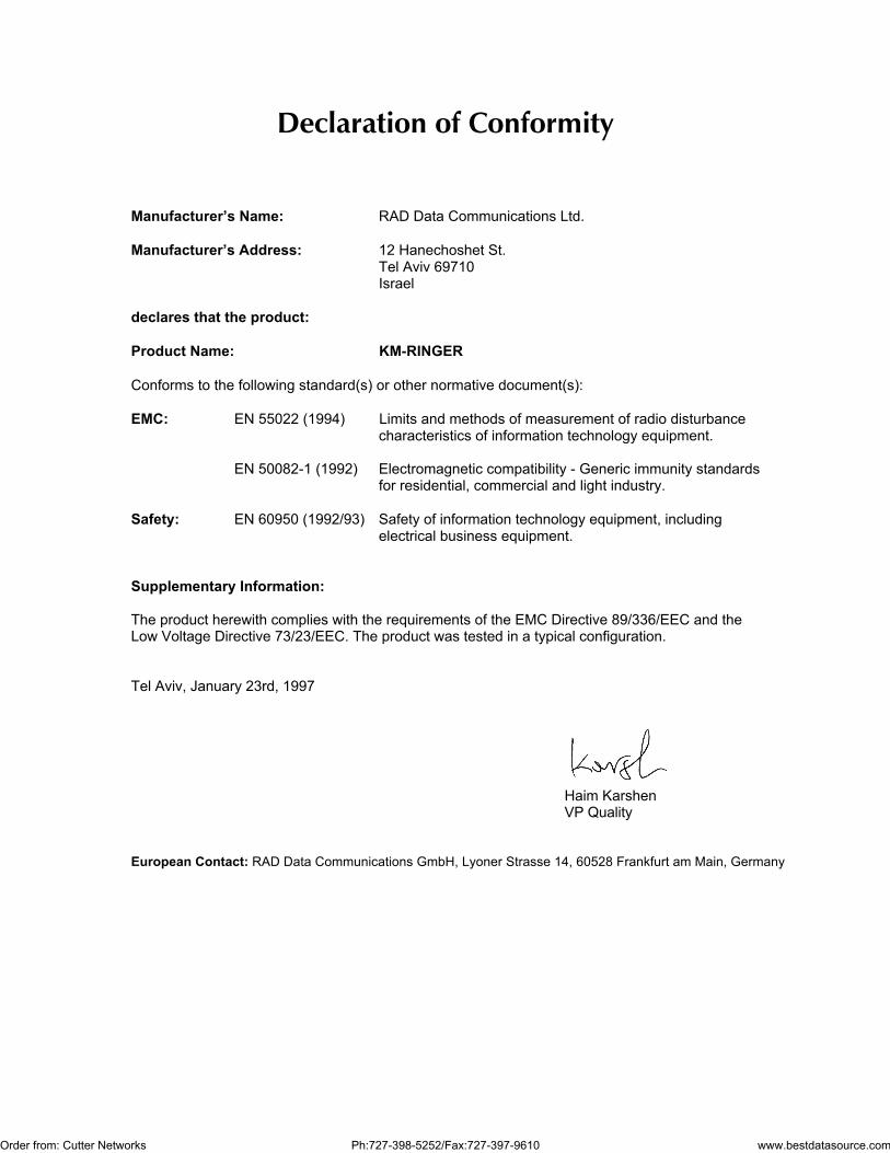
Declaration of Conformity
Manufacturer’s Name: RAD Data Communications Ltd.
Manufacturer’s Address: 12 Hanechoshet St.Tel Aviv 69710Israel
declares that the product:
Product Name: KM-RINGER
Conforms to the following standard(s) or other normative document(s):
EMC: EN 55022 (1994) Limits and methods of measurement of radio disturbancecharacteristics of information technology equipment.
EN 50082-1 (1992) Electromagnetic compatibility - Generic immunity standardsfor residential, commercial and light industry.
Safety: EN 60950 (1992/93) Safety of information technology equipment, includingelectrical business equipment.
Supplementary Information:
The product herewith complies with the requirements of the EMC Directive 89/336/EEC and theLow Voltage Directive 73/23/EEC. The product was tested in a typical configuration.
Tel Aviv, January 23rd, 1997
Haim KarshenVP Quality
European Contact: RAD Data Communications GmbH, Lyoner Strasse 14, 60528 Frankfurt am Main, Germany
Order from: Cutter Networks Ph:727-398-5252/Fax:727-397-9610 www.bestdatasource.com

i
Contents
CHAPTER 1 INTRODUCTION1.1 Overview ....................................................................................................................... 1-1
Purpose ................................................................................................................................ 1-1Versions................................................................................................................................ 1-1
1.2 Physical Description....................................................................................................... 1-21.3 Functional Description ................................................................................................... 1-3
Functional Block Diagram ..................................................................................................... 1-3Using the Ring Output Voltage .............................................................................................. 1-4
1.4 Technical Data............................................................................................................... 1-4
CHAPTER 2 INSTALLATION AND OPERATION2.1 Introduction ................................................................................................................... 2-12.2 Site Requirements .......................................................................................................... 2-1
AC Power ............................................................................................................................. 2-1DC Power............................................................................................................................. 2-1Grounding ............................................................................................................................ 2-1Module Handling Precautions ............................................................................................... 2-2Ambient Requirements ......................................................................................................... 2-2
2.3 Equipment Needed........................................................................................................ 2-22.4 KM-Ringer Front Panels.................................................................................................. 2-3
KM-Ringer Front Panels......................................................................................................... 2-3
2.5 Installation Procedure .................................................................................................... 2-4General ................................................................................................................................ 2-4Mechanical Installation.......................................................................................................... 2-4Input Power Connection ....................................................................................................... 2-4Connection of Output Voltages ............................................................................................. 2-4
2.6 Operating Procedures .................................................................................................... 2-5Turn On ............................................................................................................................... 2-5Turn Off ............................................................................................................................... 2-5
CHAPTER 3 TROUBLESHOOTING3.1 Introduction ................................................................................................................... 3-13.2 Troubleshooting ............................................................................................................. 3-1
Order from: Cutter Networks Ph:727-398-5252/Fax:727-397-9610 www.bestdatasource.com

ii
List of Figures
Figure 1-1 KM-Ringer, General View ............................................................................................ 1-2
Figure 1-2 KM-Ringer, Functional Block Diagram........................................................................... 1-3
Figure 2-1 KM-Ringer Front Panels .............................................................................................. 2-3
List of Tables
Table 3-1 Troubleshooting Instructions .......................................................................................... 3-1
Order from: Cutter Networks Ph:727-398-5252/Fax:727-397-9610 www.bestdatasource.com

Overview 1-1
Chapter 1Introduction
1.1 Overview
Purpose The KM-Ringer is a 3U-high DC feed power supply (ringer) module for theKilomux-2000 and Kilomux-2100 family of multiplexers.
The KM-Ringer module is completely encased in a protective metal case, andtherefore it can also be used as a stand-alone unit to provide feed voltages toother equipment, e.g., Megaplex-2100, Megaplex-2100H, MAXcess-3000, etc.
Note In this manual, the generic term Kilomux is used when the information isapplicable to both the Kilomux-2000 and Kilomux-2100. The completeequipment designation is used for information applicable to a specificequipment version.
The KM-Ringer supplies all the voltages required by voice/fax and ISDN basicrate access modules: -24 VDC or -48 VDC for feed, as well as +60/+72 VDCfor generating the ring signal (required by certain FXS interface modules). TheKM-Ringer can provide DC power for up to 32 voice/fax channels; the numberof ISDN channels that can be supported depends on the required currentand the ISDN DC loop resistance (determined by the pair gage and linelength).
The connection of the DC voltages generated by the KM-Ringer module ismade by a cable connected to its front-panel connector.
Versions The KM-Ringer can be ordered in AC and DC input voltage versions:
• The AC input option is for 115 to 230 VAC (±10%). The AC-poweredKM-Ringer provides -48 VDC feed voltage and +72 VDC ring voltage.
• The DC input options are -24 VDC and -48 VDC: KM-Ringer operating on -24 VDC provides -24 VDC feed voltage and
+60 VDC ring voltage. KM-Ringer operating on -48 VDC provides -48 VDC feed voltage and
+60 VDC ring voltage.
Order from: Cutter Networks Ph:727-398-5252/Fax:727-397-9610 www.bestdatasource.com

Introduction KM-Ringer Installation and Operation Manual
1-2 Physical Description
1.2 Physical DescriptionThe KM-Ringer is a three-slot wide module, intended for installation in aKilomux chassis. Module height is 3U. Figure 1-1 shows a general view of atypical AC-powered KM-Ringer. The DC-powered KM-Ringer version issimilar, except for the POWER connector.
Figure 1-1 KM-Ringer, GeneralView
The KM-Ringer has a protective case, and can also be operated as astand-alone unit, provided it is properly grounded.
The KM-Ringer front panel includes two indicators that light when themodule provides normal battery (feed) and ring output voltages.
The external power connector and the POWER on/off switch are located onthe module panel. The connection of the output voltages is made through a3-pin circular OUTPUT connector, also located on the module front panel.
The KM-Ringer does not include cooling fans. To improve cooling andreduce heat transfer to adjacent modules, it is recommended to install theKM-Ringer in the three rightmost slots of the Kilomux chassis.
Order from: Cutter Networks Ph:727-398-5252/Fax:727-397-9610 www.bestdatasource.com

KM-Ringer Installation and Operation Manual Introduction
Functional Description 1-3
1.3 Functional Description
Functional BlockDiagram
Figure 1-2 shows the functional block diagram of an AC-powered KM-Ringermodule, which provides -48 VDC and +72 VDC outputs.
The AC-powered KM-Ringer includes two AC/DC converters powered from115 to 230 VAC (±10%) input.
PowerSwitch
Fuse
KM-RINGER
AC InputPower
Connector
OUTPUT123
BATTERYVOLTAGE
RINGVOLTAGE
+72 VDCGND
-48 VDC-48 VDCAC/DC
Converter
+72 VDCAC/DC
Converter
Figure 1-2 KM-Ringer, Functional Block Diagram
The AC input voltage passes through a protection fuse located in the ACinput connector, and through the POWER on/off switch.
The POWER switch includes an internal indicator which lights when theKM-Ringer is turned on.
Each AC/DC converter of the KM-Ringer generates a single DC outputvoltage, which is connected to a different pin on the single front-panelOUTPUT connector. The DC output voltages depend on the KM-Ringerversion (see Section 1.1).
Note that the output voltages generated by the KM-Ringer are referenced tothe common ground.
Each output voltage is monitored by means of an indicator, located on thefront panel.
The DC-powered KM-Ringer includes DC/DC converters, which operatedirectly from the DC input voltage.
Order from: Cutter Networks Ph:727-398-5252/Fax:727-397-9610 www.bestdatasource.com

Introduction KM-Ringer Installation and Operation Manual
1-4 Technical Data
Using the RingOutput Voltage
The ring output voltage of the KM-Ringer (+60 VDC or +72 VDC) can be usedto provide an independent positive DC voltage. Certain voice modules with FXSinterfaces require this voltage to generate the 20 Hz telephone ringing voltage.
All voltages above 60 VDC are considered to be hazardous, that may causeelectrical shock or bodily injury.
1.4 Technical Data
This section lists the main KM-Ringer technical characteristics.
Nominal InputVoltage
Input Voltage Range Feed (Battery)Voltage Output
Ring Voltage Output
AC 115 to 230 VAC ±10%, 50/60 Hz -48 VDC ±5%, 0.6 A max +72 VDC ±5%, 0.5A max
-24 VDC -24 VDC (-18 to -36 VDC) -24 VDC ±5%, 0.6 A max +60 VDC ±5%, 0.5A max
-48 VDC -48 VDC (-36 to -72 VDC) -48 VDC ±5%, 0.6 A max +60 VDC ±5%, 0.5A max
Output Voltage Connections Circular 3-pin female connector on the front panel
Mechanical Data 3U-high module, occupies three slots of Kilomux chassis
Operating Conditions Same as Kilomux
Order from: Cutter Networks Ph:727-398-5252/Fax:727-397-9610 www.bestdatasource.com

Site Requirements 2-1
Chapter 2Installation and Operation
2.1 Introduction
This chapter provides installation and operation instructions for theKM-Ringer module.
2.2 Site Requirements
AC Power AC-powered KM-Ringer modules should be installed within 1.5m (5 feet) of aneasily-accessible grounded AC outlet capable of furnishing between 115 VACto 230 VAC (±10%).
DC Power DC-powered KM-Ringer modules require a -24 VDC or -48 VDC powersource (in accordance with the nominal voltage of the ordered module).
Grounding The KM-Ringer module must be properly grounded at all times. This is foryour protection and to prevent possible damage to equipment when a faultcondition, e.g., a lightning stroke or contact with high-voltage power lines,occurs on the lines connected to modules which receive feed voltage fromthe KM-Ringer outputs.
Any interruption of the protective (grounding) connection inside or outsidethe equipment, or the disconnection of the protective ground terminal canmake this equipment dangerous. Intentional interruption is prohibited.
The KM-Ringer is grounded through its metallic body to the Kilomux chassis,and in addition it is also grounded through the module power connector.Never operate KM-Ringer modules outside the Kilomux chassis, withoutproviding reliable grounding arrangements.
Before switching on this equipment and before connecting any other cable,the protective ground terminals of the equipment must be connected to aprotective ground. The grounding connection is made through the powercable, which must be inserted in a power socket (outlet) with protectiveground contact. Therefore, the power plug must always be inserted in asocket outlet provided with a protective ground contact, and the protectiveaction must not be negated by use of an extension cord (power cable)without a protective conductor (grounding).
Order from: Cutter Networks Ph:727-398-5252/Fax:727-397-9610 www.bestdatasource.com

Installation and Operation KM-Ringer Installation and Operation Manual
2-2 Equipment Needed
Module HandlingPrecautions
Never connect any cables to a KM-Ringer module if it is not installed in aproperly installed and grounded equipment chassis, and always disconnectall the cables from the module, before removing the module from thechassis.
When the module is operated as a stand-alone unit, always ensure that themodule is properly grounded before connecting any cables, and disconnectall the cables from the module before disconnecting it from the ground.
AmbientRequirements
The ambient operating conditions of the KM-Ringer are the same as for theKilomux.
2.3 Equipment Needed
The connection of the KM-Ringer output voltages to modules installed in aKilomux chassis, or to other external equipment, is made through theOUTPUT connector. The following types of cables can be used:
CBL-RINGER1 Cable for connecting an output connector to asingle module.
CBL-RINGER2 Splitter cable for connecting an outputconnector to up to two modules.
CBL-RINGER4 Splitter cable for connecting an outputconnector to up to four modules.
CBL-RINGER6 Splitter cable for connecting an outputconnector to up to six modules.
If more than six modules need to be connected, cables can be linkedtogether.
Order from: Cutter Networks Ph:727-398-5252/Fax:727-397-9610 www.bestdatasource.com

KM-Ringer Installation and Operation Manual Installation and Operation
KM-Ringer Front Panels 2-3
2.4 KM-Ringer Front Panels
KM-Ringer FrontPanels
Figure 2-1 shows typical front panels of AC- and DC-powered KM-Ringermodules.
Figure 2-1 KM-RingerFront Panels
AC-Powered Module
VOLTAGEBATTERY
RINGVOLTAGE
KM-RINGER
100-230VAC/ T 250V2A
OUTPUT
DC-Powered Module
OUTPUT
VOLTAGEBATTERY
RINGVOLTAGE
KM-RINGER
VDC-IN
0 -24-48
POWER POWER
The module panel includes the following components:
OUTPUT Connector 3-pin circular female connector for the outputvoltages. Connector wiring is as follows:
213
Ring Voltage+72 or +60 VDC
Feed (Battery) Voltage-48 or -24 VDC
CommonGround
(0)
RING VOLTAGE Lights when the ring output voltage is within theallowable limits.
BATTERY VOLTAGE Lights when the line feed output voltage iswithin the allowable limits.
Power Connector AC-powered module: includes a standard IECsocket with integral fuses. Fuse ratings aremarked near the connector (2A/250 V).DC-powered module: includes a plastic 3-pinterminal block type connector.
POWER Switch Turns the KM-Ringer on.
Order from: Cutter Networks Ph:727-398-5252/Fax:727-397-9610 www.bestdatasource.com

Installation and Operation KM-Ringer Installation and Operation Manual
2-4 Installation Procedure
2.5 Installation Procedure
General When the KM-Ringer is not used as a stand-alone unit, it can be installed inthree adjacent slots of a Kilomux unit. Whenever possible, install theKM-Ringer module in the three rightmost slots of the chassis.
The KM-Ringer is fastened to the chassis by means of two captive screws.
MechanicalInstallation
Install the KM-Ringer using the following procedure:
• Set the POWER switch to OFF.
• Insert the module in the assigned position.
• Fasten the two module screws.
Input PowerConnection
Connect the power cable to the POWER connector, and then connect theother end to the prescribed power outlet.
Connection ofOutput Voltages
• Connect the male 3-pin connector of the desired connection cable(e.g., CBL-RINGER1) to the OUTPUT connector of the KM-Ringer.
• Connect the female 3-pin connector of the cable to the DC inputconnector of the voice or ISDN module.
Alternately, use a CBL-RINGER2, CBL-RINGER4, or CBL-RINGER6 cable toconnect the KM-Ringer to several modules.
If you must connect more than six modules to the KM-Ringer output, youmay use cables as splitters.
For example, to distribute the feed and ring voltages generated by oneKM-Ringer to 12 modules, you need one CBL-RINGER2 and twoCBL-RINGER6 cables, connected as follows:
1. Connect the male connector of the CBL-RINGER2 cable to theOUTPUT connector of the KM-Ringer.
2. Connect the male connectors of two CBL-RINGER6 cables to thefemale connectors at the two ends of the CBL-RINGER2 cable.
Note To feed modules installed in chassis types that distribute voltages throughtheir internal power supply bus (e.g., Megaplex-2100, MAXcess-3000, etc.),connect the cable connector to the DC input connector of the chassis powersupply module. Check that the internal jumpers of the modules that receivethe KM-Ringer voltages are set to use internal feeding.
Order from: Cutter Networks Ph:727-398-5252/Fax:727-397-9610 www.bestdatasource.com

KM-Ringer Installation and Operation Manual Installation and Operation
Operating Procedures 2-5
2.6 Operating Procedures
All voltages above 60 VDC are considered to be hazardous, that maycause electrical shock or bodily injury.
To prevent damage to connected equipment due to incorrect application offeed voltages, strictly observe the following procedures.
Turn On The KM-Ringer must always be turned on after the connected user’sequipment, e.g., Kilomux, is already operating.
• To turn the KM-Ringer on, set its POWER switch to ON. The outputvoltage indicators must turn on and light steadily.
Turn Off The KM-Ringer must always be turned off before the equipment connectedto its OUTPUT connector is turned off.
• To turn the KM-Ringer off, set its POWER switch to OFF. The KM-Ringerindicators will turn off.
Caution Always turn the KM-Ringer off before removing and installing a voice/ISDNmodule in any connected chassis. After the module has beeninstalled/removed, the KM-Ringer can be turned back on.
Order from: Cutter Networks Ph:727-398-5252/Fax:727-397-9610 www.bestdatasource.com

Installation and Operation KM-Ringer Installation and Operation Manual
2-6 Operating Procedures
Order from: Cutter Networks Ph:727-398-5252/Fax:727-397-9610 www.bestdatasource.com

������������ ���
��������
��� ����������
�����������������
�������������� �������������������������������������������
�������� ����������
�������������������������������������������������������������������������������������������� ��������
�������� ������ ���������� �������
��� �������� ������������������
� ����� !��"�����������������������
��� #��$�������������������"��������������������������������������%���$��������������������������������������������������"����������
&�� #��$����'#����(#���"��)�������������"������������������*���������������"���������"������������������"�����������������
������� ������������������������������ ��������������%������������$���+����
,�� ��������������� ��-�(����������'#���"���������������"�-�������������������������������������������������������������������������"�������������� ���������������������$������������������������-�������"�%�������"�������������������������������)&'.&/01��������"*��'����������������������������������������������������������������
�����
���� ������� ����������������������������������� ����������������������������������������������������������� �������������� ��
2�� ����������"�������
Order from: Cutter Networks Ph:727-398-5252/Fax:727-397-9610 www.bestdatasource.com

������������ � !"������������������������������������
��� ������������
�������� ������ ���������� ������� ��������
��� �������� ������������������
& '������� �����������������������
��� #��$�������� !���"�������������������������%�������������������"����������� �
&�� �������������������%���������������������%�����"��������0�������
,�� ������������������������-���������������������������������������%������������������� ���-
• �������������������%�������������������-���������������������������"�������������������%���������������
• ������������������������%���������3��������������������������
, ���3���������������������������������4��4������������������ ���3����� ����
2���#��$�������3����� ��������������������������������3��������� �����������������%��������������������"������&���� �
/���#��$���������������������������������������������������������
5���#��$������3��������������������������������������������������������������6����� �����
7��������������������
Order from: Cutter Networks Ph:727-398-5252/Fax:727-397-9610 www.bestdatasource.com

DC Power Supply Connection – Terminal Block Connector
Note: Ignore this supplement if the unit is AC-powered.
DC-powered units are equipped with a plastic 3-pin VDC-IN power input connector, located on the unitrear panel. Supplied with such a unit, is a mating Terminal Block (TB) type connector plug for attaching toyour power supply cable.
Connect the wires of your power supply cable to the TB plug, according to the voltage polarity andassembly instructions provided below.
Caution: Prepare the connections to the TB plug before inserting it into the VDC-IN connector.
Preparing and Connecting the TB Plug
Refer to Figure 1 for assistance.
1. Strip the insulation of your power supplycable wires according to the dimensionsshown.
2. Place each wire lead into theappropriate TB plug terminalaccording to the voltage polaritymapping shown in Figure 2.(If the terminal is not already open,loosen its terminal screw.)
3. Tighten the three terminal screws.
4. Pull a nylon cable tie (supplied) aroundthe power supply cable to secure itfirmly to the TB plug grip (pass the tiethrough the holes on the grip).
5. Isolate the exposed terminal screws / wireleads using a plastic sleeve or insulating tape, to prevent the possibility of short-circuit.
6. Connect the assembled power supply cable to the unit by inserting the TB plug into the unit’sVDC-IN connector, until it snaps into place.
DC Power Supply Wire Voltage Polarity
Refer to Figure 2 for proper mapping of thepower supply wire leads to the TB plug’s threeterminals.
Warning:Reversing the wire voltage polarity can causeserious damage to the unit!
DC Power Input Connector
(on un it pane l)
Mating TB C onnector
Plug
See Figure 2 fo r m apping
Term ina l screws
W ire stripping d im ensions
Figure 1
DC pow er cab le
Ny lon cable tie
TB plug g rip
5 m m
20 m m
For -24 or -48 VDC input: For +24 or +48 VDC input:
0 0-48 (or -24 ) -48 (or -24 )
C hass is(fram e)G round
C hass is(fram e)G round
V D C input(nega tive po le)
V D C input(pos itive pole )
G round(0 )
G round(0 )
Figure 2
SUP-220-04/00
Order from: Cutter Networks Ph:727-398-5252/Fax:727-397-9610 www.bestdatasource.com


![Cis TelePresenCo Ce isDn link...ISDN PRI Interface 1 testShutdown ISDN BRI Interface [1..4] testLoopmode ISDN BRI Interface [1..4] testPattern Cisco telePresence ISDN Link Administrator](https://img.pdfslide.us/doc/110x75/6131c5191ecc51586944f1c2/cis-telepresenco-ce-isdn-link-isdn-pri-interface-1-testshutdown-isdn-bri-interface.jpg)