Embed Size (px)
Citation preview

Klaus Mollenhauer � Helmut Tschoeke
Handbook of Diesel Engines
Klaus Mollenhauer � Helmut Tschoeke
Handbook of DieselEnginesWith 584 Figures and 86 Tables
1 3
EditorsProf. Dr.-Ing. Klaus MollenhauerOrber Str. 2514193 [email protected]
Prof. Dr.-Ing. Helmut TschoekeOtto von Guericke University MagdeburgInstitute of Mobile SystemsUniversitatsplatz 239106 [email protected]
TranslatorKrister G. E. JohnsonOtto-von-Guericke-Strass 56 b39104 MagdeburgGermany
ISBN 978-3-540-89082-9 e-ISBN 978-3-540-89083-6DOI 10.1007/978-3-540-89083-6Springer Heidelberg Dordrecht London New York
Library of Congress Control Number: 2010924045
# Springer-Verlag Berlin Heidelberg 2010This work is subject to copyright. All rights are reserved, whether the whole or part of the material is concerned, specifically the rights oftranslation, reprinting, reuse of illustrations, recitation, broadcasting, reproduction on microfilm or in any other way, and storage in databanks. Duplication of this publication or parts thereof is permitted only under the provisions of the German Copyright Law of September 9,1965, in its current version, and permission for use must always be obtained from Springer. Violations are liable to prosecution under theGerman Copyright Law.The use of general descriptive names, registered names, trademarks, etc. in this publication does not imply, even in the absence of a specificstatement, that such names are exempt from the relevant protective laws and regulations and therefore free for general use.
Cover design: WMXDesign GmbH, Heidelberg
Printed on acid-free paper
Springer is part of Springer Science+Business Media (www.springer.com)
Preface
This machine is destined to completely revolutionizeengine engineering and replace everything that exists.(From Rudolf Diesel’s letter of October 2, 1892 to thepublisher Julius Springer.)
Although Diesel’s stated goal has never been fullyachievable of course, the diesel engine indeed revolu-tionized drive systems. This handbook documents thecurrent state of diesel engine engineering and technol-ogy. The impetus to publish a Handbook of DieselEngines grew out of ruminations on Rudolf Diesel’stransformation of his idea for a rational heat engineinto reality more than 100 years ago. Once the patentwas filed in 1892 and work on his engine commencedthe following year, Rudolf Diesel waited another 4 yearsuntil the Association of German Engineers providedhim a platform to present his engine to the public at itsconvention in Kassel on June 16, 1897. The enginecame to bear the name of its ingenious inventor soonthereafter.
The editors and publisher intend this English edi-tion of the handbook to furnish readers outside Ger-man-speaking regions a scholarly and practical presen-tation of the current state of the diesel engine and itslarge range of applications. The handbook has not onlybeen conceived for diesel experts but also ‘‘diesel lay-persons’’ with prior knowledge of engineering or atleast an interest in technology. Furthermore, it isintended to benefit students desiring a firsthandcomprehensive and sound overview of diesel engineengineering and technology and its state ofdevelopment.
These aims are reflected in the book’s five-partstructure. Part I provides a brief history of the dieselengine followed by sections on the fundamentals,including supercharging systems, diesel engine com-bustion, fuels and modern injection systems. Parts II–IV treat the loading and design of selected components,diesel engine operation, the pollution this causes andthe increasingly important measures to reduce it. PartV presents the entire range of engines from small single
cylinder diesel engine up through large low speed two-stroke diesel engines. An appendix lists the mostimportant standards and regulations for diesel engines.
Further development of diesel engines as economiz-ing, clean, powerful and convenient drives for road andnonroad use has proceeded quite dynamically in thelast twenty years in particular. In light of limited oilreserves and the discussion of predicted climatechange, development work continues to concentrateon reducing fuel consumption and utilizing alternativefuels while keeping exhaust as clean as possible as wellas further increasing diesel engine power density andenhancing operating performance. Development isoriented toward the basic legal conditions, customerdemands and, not least, competition with gasolineengines, which are still considered the benchmark carengine in many sectors.
The topics to be treated were weighed with all this inmind: In addition to engine internal measures thatreduce exhaust emissions with the aid of new combus-tion systems and new fuels, the section on Exhaust GasAftertreatment deserves particular mention. The oxida-tion catalytic converters introduced in the car sector asstandard in the 1990s will soon no longer meet themounting requirements for air hygiene; particulate fil-ters and nitrogen oxide reduction systems, e.g. SCR andstorage catalysts, have become standard.
New combustion systems with a larger share ofpremixed, homogeneous combustion than normaldiffusion combustion are just as much the subject ofthis handbook as the refinement of supercharging toenhance the power output, increase the peak cylinderpressure and thus limit load as the brake mean effec-tive pressure increases. Quickly emerging as the opti-mal injection system when the car sector switchedfrom indirect to direct injection at the end of the1990s, the common rail system also came to be used– initially only experimentally – for larger dieselengines at the start of the new millennium. Thecommon rail system is now standard in diesel engines
V
of virtually every size. Hence, reflecting current butby far not yet finalized development, this handbooktreats the different designs, e.g. with solenoid valve-controlled or piezo-actuated injectors, in detail.Ample space has accordingly also been given to elec-tronics with its diverse options to control processes inthe engine.
To be able meet the expectations and demandsconnected with a Handbook of Diesel Engines, werelied as much on the collaboration of outstandingengineers from the engine industry as on the researchfindings of professors at universities of applied sciencesand universities. After all, a particularly close connec-tion has existed between theory and practice, betweenacademia and industry, in engine research since Die-sel’s day, his invention itself being based on the engi-neering of his day.
Thanks to the work of many generations of engi-neers, scientists, researchers and professors, the dieselengine continues to be the most cost effective internalcombustion engine and has evolved into an advancedhigh-tech product.
We would like to thank all the authors – whetherexperts working in industry where the utmost dedica-tion is demanded or our colleagues in academia wherethe days of creative leisure have long since become athing of the past – for their collaboration, their readyacceptance of our ideas and the many fruitful discus-sions. We would also like to extend our gratitude to thecompanies that allowed their employees to work on theside, supported the compilation of texts and masterillustrations and provided material. Acknowledgementis also due the many helpers at companies and insti-tutes for their contributions without which such anextensive book manuscript could never have beenproduced.
Particularly special thanks go to the Diesel SystemsDivision at Robert Bosch GmbH for the technical andfinancial support, which made it possible to completethis extensive work in the first place.
Despite the sometimes hectic pace and considerableadditional work, the editors tremendously enjoyedtheir collaboration with the authors, the publisher andall the other collaborators.
Berlin, Germany,Magdeburg, GermanySeptember 2009
Klaus MollenhauerHelmut Tschoeke
My engine continues to make great advances. . . . (From Rudolf Diesel’s letter of July 3, 1895 to his wife.)
VI Preface
Contents
Contributors . . . . . . . . . . . . . . . . . . . . . IX
Part I The Diesel Engine Cycle . . . . 1
1 History and Fundamental Principles of theDiesel Engine (Klaus Mollenhauer andKlaus Schreiner) . . . . . . . . . . . . . . . . 31.1 The History of the Diesel Engine . . . . . . 31.2 Fundamentals of Engine Engineering . . . . 71.3 Combustion Cycle Simulation . . . . . . . 18Literature . . . . . . . . . . . . . . . . . . . 29
2 Gas Exchange and Supercharging (Helmut Pucher) . . 312.1 Gas Exchange . . . . . . . . . . . . . . . 312.2 Diesel Engine Supercharging . . . . . . . . 382.3 Programmed Gas Exchange
Simulation . . . . . . . . . . . . . . . . 56Literature . . . . . . . . . . . . . . . . . . . 59
3 Diesel Engine Combustion (Klaus B. Binder) . . . . . 613.1 Mixture Formation and Combustion . . . . 613.2 Design Features . . . . . . . . . . . . . . 693.3 Alternative Combustion Processes . . . . . . 733.4 Process Simulation of Injection Characteristic
and Rate of Heat Release . . . . . . . . . . 74Literature . . . . . . . . . . . . . . . . . . . 75
4 Fuels (Gerd Hagenow, Klaus Reders, Hanns-ErhardHeinze, Wolfgang Steiger, Detlef Zigan, and DirkMooser) . . . . . . . . . . . . . . . . . . . . 774.1 Automotive Diesel Fuels . . . . . . . . . . 774.2 Alternative Fuels . . . . . . . . . . . . . 944.3 Operation of Marine and Stationary
Engines with Heavy Fuel Oil . . . . . . . 1034.4 Fuel Gases and Gas Engines . . . . . . . 114Literature . . . . . . . . . . . . . . . . . . 124
5 Fuel Injection Systems (Walter Egler, Rolf JurgenGiersch, Friedrich Boecking, Jurgen Hammer,Jaroslav Hlousek, Patrick Mattes, Ulrich Projahn,Winfried Urner, and Bjorn Janetzky) . . . . . . 1275.1 Injection Hydraulics . . . . . . . . . . . 127
5.2 Injection Nozzles and Nozzle Holders . . . 1295.3 Injection Systems . . . . . . . . . . . . 1375.4 Injection System Metrology . . . . . . . . 170Literature . . . . . . . . . . . . . . . . . . 173Further Literature . . . . . . . . . . . . . . 173Further Literature on Section 5.2 . . . . . . . . 174
6 Fuel Injection System Control Systems (Ulrich Projahn,Helmut Randoll, Erich Biermann, Jorg Bruckner,Karsten Funk, Thomas Kuttner, Walter Lehle, andJoachim Zuern) . . . . . . . . . . . . . . . 1756.1 Mechanical Control . . . . . . . . . . . 1756.2 Electronic Control . . . . . . . . . . . . 1766.3 Sensors . . . . . . . . . . . . . . . . . 1846.4 Diagnostics . . . . . . . . . . . . . . . 1866.5 Application Engineering . . . . . . . . . 189Literature . . . . . . . . . . . . . . . . . . 191Further Literature . . . . . . . . . . . . . . 191
Part II Diesel Engine Engineering . . 193
7 Engine Component Loading (Dietmar Pinkernell andMichael Bargende) . . . . . . . . . . . . . . 1957.1 Mechanical and Thermal Loading
of Components . . . . . . . . . . . . . 1957.2 Heat Transfer and Thermal Loads
in Engines . . . . . . . . . . . . . . . 202Literature . . . . . . . . . . . . . . . . . . 217Further Literature . . . . . . . . . . . . . . 219
8 Crankshaft Assembly Design, Mechanicsand Loading (Eduard Kohler, Eckhart Schopf, andUwe Mohr) . . . . . . . . . . . . . . . . . 2218.1 Designs and Mechanical Properties of
Crankshaft Assemblies . . . . . . . . . . 2218.2 Crankshaft Assembly Loading . . . . . . 2288.3 Balancing of Crankshaft Assembly Masses . 2368.4 Torsional Crankshaft Assembly
Vibrations . . . . . . . . . . . . . . . 2508.5 Bearings and Bearing Materials . . . . . . 2598.6 Piston, Piston Rings and Piston Pins . . . . 270Literature . . . . . . . . . . . . . . . . . . 287Further Literature . . . . . . . . . . . . . . 290
VII
9 Engine Cooling (Klaus Mollenhauer andJochen Eitel) . . . . . . . . . . . . . . . . . 2919.1 Internal Engine Cooling . . . . . . . . . 2919.2 External Engine Cooling Systems . . . . . 309Literature . . . . . . . . . . . . . . . . . . 336
10 Materials and Their Selection (Johannes Betz) . . . . 33910.1 The Importance of Materials for Diesel
Engines . . . . . . . . . . . . . . . . 33910.2 Technical Materials for Engine Components . 33910.3 Factors for Material Selection . . . . . . 34810.4 Service Life Concepts and Material Data . . . 34810.5 Service Life Enhancing Processes . . . . . 34910.6 Trends in Development . . . . . . . . . 352Literature . . . . . . . . . . . . . . . . . . 354Further Literature . . . . . . . . . . . . . . 355
Part III Diesel Engine Operation . . 357
11 Lubricants and the Lubrication System(Hubert Schwarze) . . . . . . . . . . . . . . 35911.1 Lubricants . . . . . . . . . . . . . . . 35911.2 Lubrication Systems . . . . . . . . . . 370Literature . . . . . . . . . . . . . . . . . . 376
12 Start and Ignition Assist Systems (Wolfgang Dresslerand Stephan Ernst) . . . . . . . . . . . . . . 37712.1 Conditions for the Auto-Ignition of Fuel . 37712.2 Fuel Ignition Aids . . . . . . . . . . . 37812.3 Start and Ignition Assist Systems . . . . . 37912.4 Cold Start, Cold Running Performance
and Cold Running Emissions for Cars . . 38312.5 Conclusion . . . . . . . . . . . . . . 386Literature . . . . . . . . . . . . . . . . . . 386Further Literature . . . . . . . . . . . . . . 386
13 Intake and Exhaust Systems (Oswald Parr,Jan Kruger, and Leonhard Vilser) . . . . . . . 38713.1 Air Cleaners . . . . . . . . . . . . . . 38713.2 Exhaust Systems . . . . . . . . . . . . 393Literature . . . . . . . . . . . . . . . . . . 398Further Literature . . . . . . . . . . . . . . 399
14 Exhaust Heat Recovery (Franz Hirschbichler) . . . . 40114.1 Basics of Waste Heat Recovery . . . . . . 40114.2 Options of Waste Heat Recovery . . . . . 404Literature . . . . . . . . . . . . . . . . . . 413
Part IV Environmental Pollutionby Diesel Engines . . . . . 415
15 Diesel Engine Exhaust Emissions (Helmut Tschoeke,Andreas Graf, Jurgen Stein, Michael Kruger, JohannesSchaller, Norbert Breuer, Kurt Engeljehringer,and Wolfgang Schindler) . . . . . . . . . . . 41715.1 General Background . . . . . . . . . . 417
15.2 Emission Control Legislation . . . . . . 42615.3 Pollutants and Their Production . . . . . 44315.4 In-Engine Measures for Pollutant
Reduction . . . . . . . . . . . . . . . 44915.5 Exhaust Gas Aftertreatment . . . . . . . 45515.6 Emissions Testing . . . . . . . . . . . 469Literature . . . . . . . . . . . . . . . . . . 483Further Literature . . . . . . . . . . . . . . 485
16 Diesel Engine Noise Emission (Bruno M. Spessertand Hans A. Kochanowski) . . . . . . . . . . 48716.1 Fundamentals of Acoustics . . . . . . . 48716.2 Development of Engine Noise
Emission . . . . . . . . . . . . . . . 48716.3 Engine Surface Noise . . . . . . . . . . 48916.4 Aerodynamic Engine Noises . . . . . . . 49816.5 Noise Reduction by Encapsulation . . . . 49916.6 Engine Soundproofing . . . . . . . . . 502Literature . . . . . . . . . . . . . . . . . . 502
Part V Implemented DieselEngines . . . . . . . . . 505
17 Vehicle Diesel Engines (Fritz Steinparzer, KlausBlumensaat, Georg Paehr, Wolfgang Held, andChristoph Teetz) . . . . . . . . . . . . . . . . 50717.1 Diesel Engines for Passenger Cars . . . . 50717.2 Diesel Engines for Light Duty
Commercial Vehicles . . . . . . . . . . 52117.3 Diesel Engines for Heavy Duty Commercial
Vehicles and Buses . . . . . . . . . . . 52817.4 High Speed High Performance
Diesel Engines . . . . . . . . . . . . . 544Literature . . . . . . . . . . . . . . . . . . 556Further Literature . . . . . . . . . . . . . . 557
18 Industrial and Marine Engines (Gunter Kampichler,Heiner Bulte, Franz Koch, and Klaus Heim) . . . 559
18.1 Small Single Cylinder DieselEngines . . . . . . . . . . . . . . . . 559
18.2 Stationary and Industrial Engines . . . . 56818.3 Medium Speed Four-Stroke
Diesel Engines . . . . . . . . . . . . . 57618.4 Two-Stroke Low Speed
Diesel Engines . . . . . . . . . . . . . 592Literature . . . . . . . . . . . . . . . . . . 607
Standards and Guidelines for Internal Combustion Engines . 609
Index . . . . . . . . . . . . . . . . . . . . . . 621
VIII Contents
Contributors
Michael Bargende, Prof. Dr.-Ing., Universitat Stuttgart,Stuttgart, Germany, [email protected]
Johannes Betz, MTU Friedrichshafen GmbH,Friedrichshafen, Germany, [email protected]
Erich Biermann, Dr.-Ing., Robert Bosch GmbH, DieselSystems, Stuttgart, Germany,[email protected]
Klaus B. Binder, Prof. Dr.-Ing., Deizisau, Germany,[email protected]
Klaus Blumensaat, Volkswagen AG, Wolfsburg, Germany,[email protected]
Friedrich Boecking, Robert Bosch GmbH, Diesel Systems,Stuttgart, Germany, [email protected]
Norbert Breuer, Dr.-Ing., Robert Bosch GmbH, DieselSystems, Stuttgart, Germany,[email protected]
Jorg Bruckner, Dr., Robert Bosch GmbH, Diesel Systems,Stuttgart, Germany, [email protected]
Heiner Bulte, Dr.-Ing., Deutz AG, Koln, Germany,[email protected]
Wolfgang Dressler, Dr., Robert Bosch GmbH, DieselSystems, Stuttgart, Germany,[email protected]
Walter Egler, Dr.-Ing., Robert Bosch GmbH, Diesel Systems,Stuttgart, Germany, [email protected]
Jochen Eitel, Behr GmbH & Co. KG, Stuttgart, Germany,[email protected]
Kurt Engeljehringer, AVL List GmbH, Graz, Austria,[email protected]
Stephan Ernst, Dr.-Ing., Robert Bosch GmbH, DieselSystems, Stuttgart, Germany, [email protected]
Karsten Funk, Dr.-Ing., Robert Bosch GmbH, DieselSystems, Stuttgart, Germany, [email protected]
Rolf Jurgen Giersch, Dipl.-Ing., Robert Bosch GmbH, DieselSystems, Stuttgart, Germany,[email protected]
Andreas Graf, Dipl.-Ing., Daimler AG, Stuttgart, Germany,[email protected]
Gerd Hagenow, Dr., Shell Global Solutions (Deutschland)GmbH, Hamburg, Germany
Jurgen Hammer, Dr.-Ing., Robert Bosch GmbH, DieselSystems, Stuttgart, Germany,[email protected]
Klaus Heim, Wartsila Switzerland Ltd, Winterthur,Switzerland, [email protected]
Hanns-Erhard Heinze, Dr.-Ing., Magdeburg, Germany,[email protected]
Wolfgang Held, Dr.-Ing., MAN Nutzfahrzeuge AG,Nurnberg, Germany, [email protected]
Franz Hirschbichler, Dr., Munchen, Germany,[email protected]
Jaroslav Hlousek, Dipl.-Ing., KEFICO Co, Gunpo, Korea(RoK), [email protected]
Bjorn Janetzky, Dr.-Ing., Robert Bosch GmbH, DieselSystems, Stuttgart, Germany,[email protected]
Gunter Kampichler, Dipl.-Ing., Ruhstorf, GermanyFranz Koch, Dr.-Ing., MAN Diesel & Turbo SE, Augsburg,
Germany, [email protected] A. Kochanowski, Dr.-Ing., Ruhstorf, GermanyEduard Kohler, Prof. Dr.-Ing. habil., KS Aluminium
Technologie GmbH, Neckarsulm, Germany,[email protected]
Jan Kruger, Dr.-Ing., J. Eberspacher GmbH &Co. KG, Esslingen, Germany,[email protected]
Michael Kruger, Dr.-Ing., Robert Bosch GmbH, DieselSystems, Stuttgart, Germany,[email protected]
Thomas Kuttner, Dipl.-Ing., Robert Bosch GmbH, DieselSystems, Stuttgart, Germany,[email protected]
Walter Lehle, Dr. rer. nat., Robert Bosch GmbH, DieselSystems, Stuttgart, Germany, [email protected]
Patrick Mattes, Dr., Robert Bosch GmbH, Diesel Systems,Stuttgart, Germany, [email protected]
Uwe Mohr, Dr., Mahle GmbH, Stuttgart, Germany,[email protected]
Klaus Mollenhauer, Prof. Dr.-Ing., Berlin, Germany,[email protected]
Dirk Mooser, Dr.-Ing., Caterpillar Motoren GmbH & Co.KG, Kiel, Germany, [email protected]
Georg Paehr, Dr., Volkswagen AG, Wolfsburg, Germany,[email protected]
Oswald Parr, Dr.-Ing., Ludwigsburg, GermanyDietmar Pinkernell, MAN Diesel & Turbo SE, Augsburg,
GermanyUlrich Projahn, Dr.-Ing., Robert Bosch GmbH, Diesel
Systems, Stuttgart, Germany,[email protected]
IX
Helmut Pucher, Prof. Dr.-Ing., Technische Universitat Berlin,Berlin, Germany, [email protected]
Helmut Randoll, Dr. rer. nat., Robert Bosch GmbH, DieselSystems, Stuttgart, Germany, [email protected]
Klaus Reders, Dipl.-Ing., Shell Global Solutions(Deutschland) GmbH, Hamburg, Germany,[email protected]
Johannes Schaller, Dr., Robert Bosch GmbH, Diesel Systems,Stuttgart, Germany, [email protected]
Wolfgang Schindler, Dr., AVL List GmbH, Graz, Austria,[email protected]
Eckhart Schopf, Dr.-Ing., Wiesbaden, GermanyKlaus Schreiner, Prof. Dr.-Ing., HTGW Konstanz
(University of Applied Sciences), Konstanz, Germany,[email protected]
Hubert Schwarze, Prof. Dr.-Ing., TU Clausthal, Clausthal-Zellerfeld, Germany, [email protected]
Bruno M. Spessert, Prof. Dr.-Ing., FH Jena (University ofApplied Sciences), Jena, Germany, [email protected]
Wolfgang Steiger, Dr.-Ing., Volkswagen AG, Wolfsburg,Germany, [email protected]
Jurgen Stein, Daimler AG, Stuttgart, Germany,[email protected]
Fritz Steinparzer, BMW Group, Munchen, Germany,[email protected]
Christoph Teetz, Dr.-Ing., MTU Friedrichshafen GmbH,Friedrichshafen, Germany, [email protected]
Helmut Tschoeke, Prof. Dr.-Ing., Otto von GuerickeUniversitat Magdeburg, Magdeburg, Germany,[email protected]
Winfried Urner, Robert Bosch GmbH, Diesel Systems,Stuttgart, Germany, [email protected]
Leonhard Vilser, Dr.-Ing., J. Eberspacher GmbH & Co. KG,Esslingen, Germany, [email protected]
Detlef Zigan, Dr.-Ing., Kiel, Germany,[email protected]
Joachim Zuern, Dipl.-Ing., Robert Bosch GmbH, DieselSystems, Stuttgart, Germany, [email protected]
X Contributors
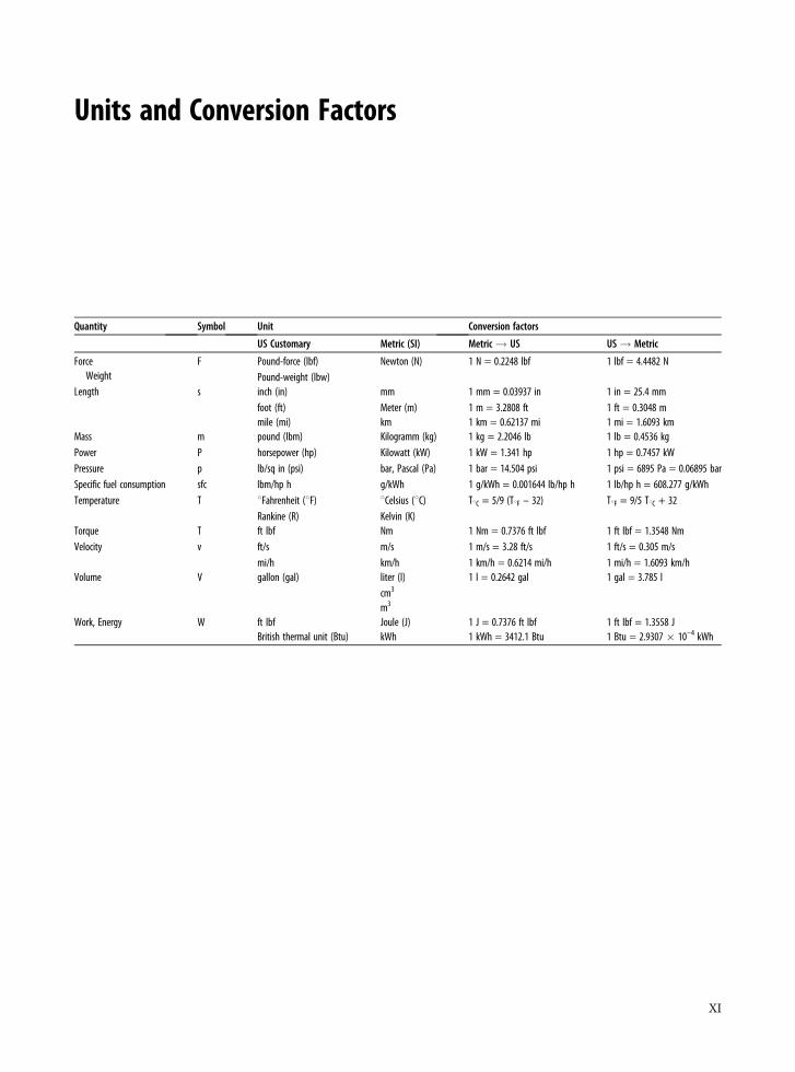
Units and Conversion Factors
Quantity Symbol Unit Conversion factors
US Customary Metric (SI) Metric! US US! Metric
ForceWeight
F Pound-force (lbf)Pound-weight (lbw)
Newton (N) 1 N = 0.2248 lbf 1 lbf = 4.4482 N
Length s inch (in)foot (ft)mile (mi)
mmMeter (m)km
1 mm = 0.03937 in1 m = 3.2808 ft1 km = 0.62137 mi
1 in = 25.4 mm1 ft = 0.3048 m1 mi = 1.6093 km
Mass m pound (lbm) Kilogramm (kg) 1 kg = 2.2046 lb 1 lb = 0.4536 kgPower P horsepower (hp) Kilowatt (kW) 1 kW = 1.341 hp 1 hp = 0.7457 kWPressure p lb/sq in (psi) bar, Pascal (Pa) 1 bar = 14.504 psi 1 psi = 6895 Pa = 0.06895 barSpecific fuel consumption sfc lbm/hp h g/kWh 1 g/kWh = 0.001644 lb/hp h 1 lb/hp h = 608.277 g/kWhTemperature T 8Fahrenheit (8F)
Rankine (R)8Celsius (8C)Kelvin (K)
T8C = 5/9 (T8F – 32) T8F = 9/5 T8C + 32
Torque T ft lbf Nm 1 Nm = 0.7376 ft lbf 1 ft lbf = 1.3548 NmVelocity v ft/s
mi/hm/skm/h
1 m/s = 3.28 ft/s1 km/h = 0.6214 mi/h
1 ft/s = 0.305 m/s1 mi/h = 1.6093 km/h
Volume V gallon (gal) liter (l)cm3
m3
1 l = 0.2642 gal 1 gal = 3.785 l
Work, Energy W ft lbfBritish thermal unit (Btu)
Joule (J)kWh
1 J = 0.7376 ft lbf1 kWh = 3412.1 Btu
1 ft lbf = 1.3558 J1 Btu = 2.9307 � 10–4 kWh
XI
Part I The Diesel EngineCycle
1 History and Fundamental Principlesof the Diesel Engine . . . . . . . . . . . . . . . . . . . . . . . . 3
2 Gas Exchange and Supercharging . . . . . . . . . . . . . . . 31
3 Diesel Engine Combustion . . . . . . . . . . . . . . . . . . . 61
4 Fuels . . . . . . . . . . . . . . . . . . . . . . . . . . . . . . . . 77
5 Fuel Injection Systems . . . . . . . . . . . . . . . . . . . . . 127
6 Fuel Injection System Control Systems . . . . . . . . . . . 175
1 History and Fundamental Principlesof the Diesel Engine
Klaus Mollenhauer and Klaus Schreiner
1.1 The History of the Diesel Engine
On February 27, 1892, the engineer Rudolf Diesel filed apatent with the Imperial Patent Office in Berlin for a ‘‘newrational heat engine’’. On February 23, 1893, he was grantedthe patent DRP 67207 for the ‘‘Working Method and Designfor Combustion Engines’’ dated February 28, 1892. This wasan important first step toward the goal Diesel had set himself,which, as can be gathered from his biography, had preoccu-pied him since his days as a university student.
Rudolf Diesel was born to German parents in Paris onMarch 18, 1858. Still a schoolboy when the Franco-PrussianWar of 1870–1871 broke out, he departed by way of Londonfor Augsburg where he grew up with foster parents. Withoutfamilial and financial backing, young Rudolf Diesel was com-pelled to take his life into his own hands and contribute to hisupkeep by, among other things, giving private lessons. Scho-larships ultimately enabled him to study at the Polytechni-kum Munchen, later the Technische Hochschule, from whichhe graduated in 1880 as the best examinee ever up to thattime.
There, in Professor Linde’s lectures on the theory of caloricmachines, the student Diesel realized that the steam engine,the dominant heat engine of the day, wastes a tremendousamount of energy when measured against the ideal energyconversion cycle formulated by Carnot in 1824 (see Sect. 1.2).What is more, with efficiencies of approximately 3%, theboiler furnaces of the day emitted annoying smoke that ser-iously polluted the air.
Surviving lecture notes document that Diesel already con-templated implementing the Carnot cycle as a student, ifpossible by directly utilizing the energy contained in coalwithout steam as an intermediate medium. While workingat Lindes Eismaschinen, which brought him from Paris toBerlin, he also ambitiously pursued the idea of a rationalengine, hoping his invention would bring him financial inde-pendence together with social advancement. He ultimately
filed and was granted the aforementioned patent [1-1] withthe following claim 1:
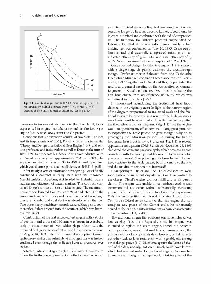
Working method for combustion engines characterized bypure air or another indifferent gas (or steam) with a workingpiston compressing pure air so intensely in a cylinder thatthe temperature generated as a result is far above the ignitiontemperature of the fuel being used (curve 1-2 of the diagramin Fig. 2), whereupon, due to the expelling piston and theexpansion of the compressed air (or gas) triggered as a result(curve 2-3 of the diagram in Fig. 2), the fuel is supplied sogradually from dead center onward that combustion occurswithout significantly increasing pressure and temperature,whereupon, after the supply of fuel is terminated, the massof gas in the working cylinder expands further (curve 3-4 ofthe diagram in Fig. 2).
Once the gas has been decompressed to the dischargepressure, heat dissipates along the isobars 4-1 (Fig. 1-1),thus ending the cycle.
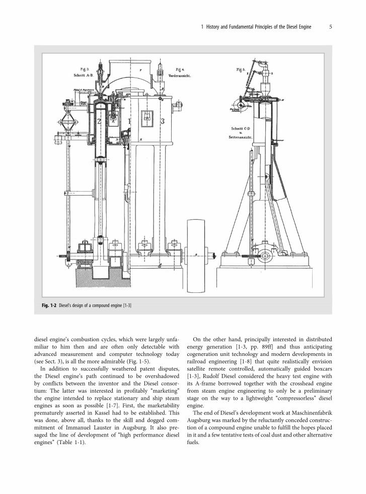
A second claim asserts patent protection of multistagecompression and expansion. Diesel proposed a three cylindercompound engine (Fig. 1-2). Adiabatic compression occurs intwo high pressure cylinders 2, 3 operating offset at 1808 andthe fuel (Diesel initially spoke of coal dust) supplied by thehopper B in top dead center auto-ignites so that isothermalcombustion and expansion occur, which turns adiabatic aftercombustion ends. The combustion gas is transferred into thedouble-acting center cylinder 1 where it completely expandsto ambient pressure and is expelled after the reversal ofmotion at the same time as the isothermal precompressionby water injection or the preceding intake of the fresh chargefor the second engine cycle that runs parallel. Thus, one cycleoccurs per revolution.
To implement the Carnot cycle, Diesel reverted to the four-stroke cycle considered ‘‘state-of-the-art’’ since NikolausOtto’s day. He believed isothermal combustion at a maximumof 8008C would enable him to keep the thermal load in theengine low enough that it would run without cooling. Thislimiting temperature requires compressions of approximately250 at with which Diesel far surpassed the ‘‘state-of-the-art’’:On the one hand, this gave the ‘‘outsider’’ Diesel the naıvete
K. Mollenhauer (*)Berlin, Germanye-mail: [email protected]
K. Mollenhauer, H. Tschoeke (eds.), Handbook of Diesel Engines, DOI 10.1007/978-3-540-89083-6_1,� Springer-Verlag Berlin Heidelberg 2010
3
necessary to implement his idea. On the other hand, firmsexperienced in engine manufacturing such as the Deutz gasengine factory shied away from Diesel’s project.
Conscious that ‘‘an invention consists of two parts: The ideaand its implementation’’ [1-2], Diesel wrote a treatise on the‘‘Theory and Design of a Rational Heat Engine’’ [1-3] and sentit to professors and industrialists as well as Deutz at the turn of1892–1893 to propagate his ideas and win over industry: Witha Carnot efficiency of approximately 73% at 8008C, heexpected maximum losses of 30 to 40% in real operation,which would correspond to a net efficiency of 50% [1-3, p. 51].
After nearly a year of efforts and strategizing, Diesel finallyconcluded a contract in early 1893 with the renownedMaschinenfabrik Augsburg AG headed by Heinrich Buz, aleading manufacturer of steam engines. The contract con-tained Diesel’s concessions to an ideal engine: The maximumpressure was lowered from 250 at to 90 at and later 30 at, thecompound engine’s three cylinders were reduced to one highpressure cylinder and coal dust was abandoned as the fuel.Two other heavy machinery manufacturers, Krupp and, soonthereafter, Sulzer entered into the contract, which was lucra-tive for Diesel.
Construction of the first uncooled test engine with a strokeof 400 mm and a bore of 150 mm was begun in Augsburgearly in the summer of 1893. Although petroleum was theintended fuel, gasoline was first injected in a powered engineon August 10, 1893 under the misguided assumption it wouldignite more easily: The principle of auto-ignition was indeedconfirmed even though the indicator burst at pressures over80 bar!
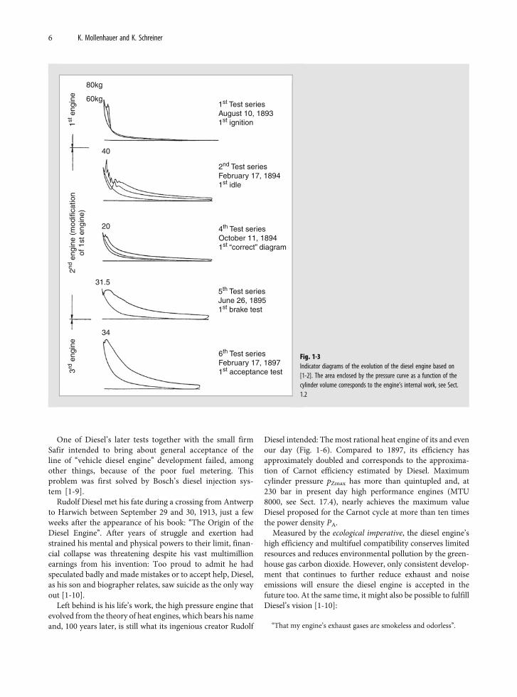
Selected indicator diagrams (Fig. 1-3) make it possible tofollow the further developments: Once the first engine, which
was later provided water cooling, had been modified, the fuelcould no longer be injected directly. Rather, it could only beinjected, atomized and combusted with the aid of compressedair. The first time the hitherto powered engine idled onFebruary 17, 1894, it became autonomous. Finally, a firstbraking test was performed on June 26, 1895: Using petro-leum as fuel and externally compressed injection air, anindicated efficiency of Zi ¼ 30.8% and a net efficiency of Ze
¼ 16.6% were measured at a consumption of 382 g/HPh.Only a revised design, the third test engine [1-4] furnished
with a single stage air pump, delivered the breakthroughthough: Professor Moritz Schroter from the TechnischeHochschule Munchen conducted acceptance tests on Febru-ary 17, 1897. Together with Diesel and Buz, he presented theresults at a general meeting of the Association of GermanEngineers in Kassel on June 16, 1897, thus introducing thefirst heat engine with an efficiency of 26.2%, which wassensational in those days [1-5]!
It necessitated abandoning the isothermal heat inputclaimed in the original patent: In light of the narrow regionof the diagram proportional to indicated work and the fric-tional losses to be expected as a result of the high pressures,even Diesel must have realized no later than when he plottedthe theoretical indicator diagrams (Fig. 1-4) that the enginewould not perform any effective work. Taking great pains notto jeopardize the basic patent, he gave thought early on toprolonging the ‘‘admission period’’, i.e. raising the line ofisothermal heat input in the p, V diagram (Fig. 1-1). A secondapplication for a patent (DRP 82168) on November 29, 1893also cited the constant pressure cycle, which was consideredconsistent with the basic patent because of its ‘‘insubstantialpressure increase’’. The patent granted overlooked the factthat, contrary to the basic patent, both the mass of the fueland the maximum temperature increased!
Unsurprisingly, Diesel and the Diesel consortium weresoon embroiled in patent disputes in Kassel. According tothe charge, Diesel’s engine did not fulfill any of his patentclaims: The engine was unable to run without cooling andexpansion did not occur without substantially increasingpressure and temperature as a function of compression.Only the auto-ignition mentioned in claim 1 took place.Yet, just as Diesel never admitted that his engine did notcomplete any phase of the Carnot cycle, he vehementlydenied to the end that auto-ignition was a basic characteristicof his invention [1-4, p. 406].
The additional charge that coal dust was not employed wasless weighty [1-5, 1-6]: Especially since his engine wasintended to replace the steam engine, Diesel, a nineteenthcentury engineer, was at first unable to circumvent coal, theprimary source of energy in his day. However, he did not ruleout other fuels as later tests, even with vegetable oils amongother things, prove [1-2]. Measured against the ‘‘state-of-the-art’’ of the day, nobody, not even Diesel, could have knownwhich fuel was best suited for the Diesel engine. Documentedby many draft designs, his ingeniously intuitive grasp of the
1
3
2
3�
3�
4�
4�
4
Volume V
Pre
ssur
e p
Fig. 1-1 Ideal diesel engine process (1-2-3-4) based on Fig. 2 in [1-1],supplemented by modified ‘‘admission periods’’ (1-2-30-40 and 1-2-30 0-40 0)according to Diesel’s letter to Krupp of October 16, 1893 [1-4, p. 404]
4 K. Mollenhauer and K. Schreiner
diesel engine’s combustion cycles, which were largely unfa-miliar to him then and are often only detectable withadvanced measurement and computer technology today(see Sect. 3), is all the more admirable (Fig. 1-5).
In addition to successfully weathered patent disputes,the Diesel engine’s path continued to be overshadowedby conflicts between the inventor and the Diesel consor-tium: The latter was interested in profitably ‘‘marketing’’the engine intended to replace stationary and ship steamengines as soon as possible [1-7]. First, the marketabilityprematurely asserted in Kassel had to be established. Thiswas done, above all, thanks to the skill and dogged com-mitment of Immanuel Lauster in Augsburg. It also pre-saged the line of development of ‘‘high performance dieselengines’’ (Table 1-1).
On the other hand, principally interested in distributedenergy generation [1-3, pp. 89ff] and thus anticipatingcogeneration unit technology and modern developments inrailroad engineering [1-8] that quite realistically envisionsatellite remote controlled, automatically guided boxcars[1-3], Rudolf Diesel considered the heavy test engine withits A-frame borrowed together with the crosshead enginefrom steam engine engineering to only be a preliminarystage on the way to a lightweight ‘‘compressorless’’ dieselengine.
The end of Diesel’s development work at MaschinenfabrikAugsburg was marked by the reluctantly conceded construc-tion of a compound engine unable to fulfill the hopes placedin it and a few tentative tests of coal dust and other alternativefuels.
Fig. 1-2 Diesel’s design of a compound engine [1-3]
1 History and Fundamental Principles of the Diesel Engine 5
One of Diesel’s later tests together with the small firmSafir intended to bring about general acceptance of theline of ‘‘vehicle diesel engine’’ development failed, amongother things, because of the poor fuel metering. Thisproblem was first solved by Bosch’s diesel injection sys-tem [1-9].
Rudolf Diesel met his fate during a crossing from Antwerpto Harwich between September 29 and 30, 1913, just a fewweeks after the appearance of his book: ‘‘The Origin of theDiesel Engine’’. After years of struggle and exertion hadstrained his mental and physical powers to their limit, finan-cial collapse was threatening despite his vast multimillionearnings from his invention: Too proud to admit he hadspeculated badly and made mistakes or to accept help, Diesel,as his son and biographer relates, saw suicide as the only wayout [1-10].
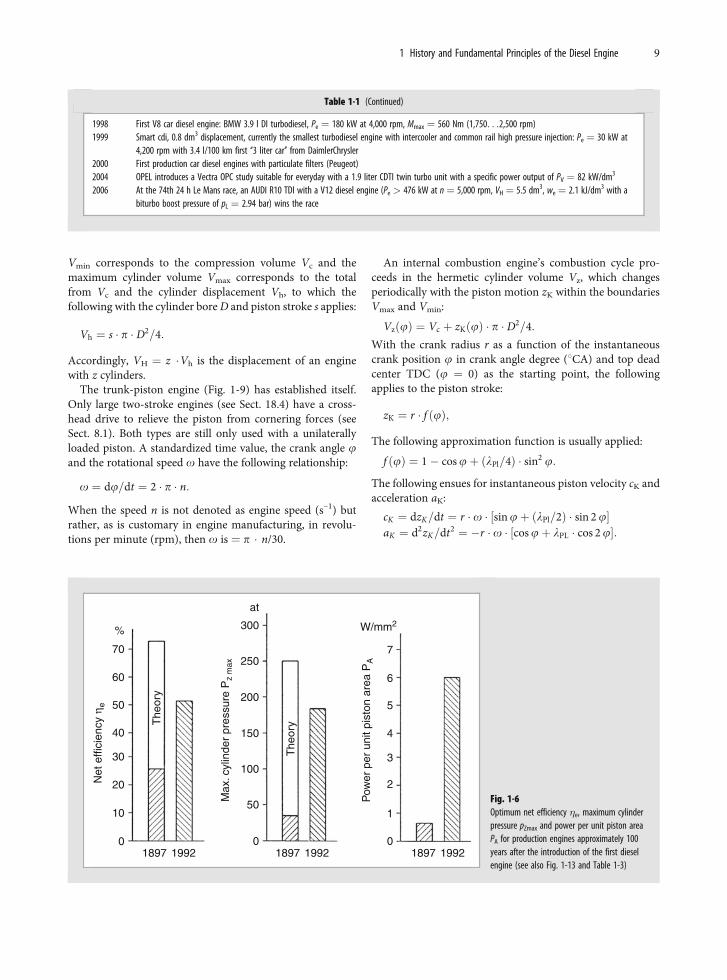
Left behind is his life’s work, the high pressure engine thatevolved from the theory of heat engines, which bears his nameand, 100 years later, is still what its ingenious creator Rudolf
Diesel intended: The most rational heat engine of its and evenour day (Fig. 1-6). Compared to 1897, its efficiency hasapproximately doubled and corresponds to the approxima-tion of Carnot efficiency estimated by Diesel. Maximumcylinder pressure pZmax has more than quintupled and, at230 bar in present day high performance engines (MTU8000, see Sect. 17.4), nearly achieves the maximum valueDiesel proposed for the Carnot cycle at more than ten timesthe power density PA.
Measured by the ecological imperative, the diesel engine’shigh efficiency and multifuel compatibility conserves limitedresources and reduces environmental pollution by the green-house gas carbon dioxide. However, only consistent develop-ment that continues to further reduce exhaust and noiseemissions will ensure the diesel engine is accepted in thefuture too. At the same time, it might also be possible to fulfillDiesel’s vision [1-10]:
‘‘That my engine’s exhaust gases are smokeless and odorless’’.
1st Test seriesAugust 10, 18931st ignition1st
eng
ine
3rd e
ngin
e2nd
eng
ine
(mod
ifica
tion
of 1
st e
ngin
e)80kg
60kg
40
20
31.5
34
2nd Test seriesFebruary 17, 18941st idle
4th Test seriesOctober 11, 18941st “correct” diagram
5th Test seriesJune 26, 18951st brake test
6th Test seriesFebruary 17, 18971st acceptance test
Fig. 1-3Indicator diagrams of the evolution of the diesel engine based on[1-2]. The area enclosed by the pressure curve as a function of thecylinder volume corresponds to the engine’s internal work, see Sect.1.2
6 K. Mollenhauer and K. Schreiner
1.2 Fundamentals of Engine Engineering
1.2.1 Introduction
Just like gasoline engines, diesel engines are, in principle,energy converters that convert chemically bound fuel energyinto mechanical energy (effective work) by supplying the heatreleased by combustion in an engine to a thermodynamiccycle.
As a function of the system boundaries of the converterrepresented as a ‘‘black box’’, the energy balance (Fig. 1-7) is:
EB þ EL þWe þ S EV ¼ 0:
If the energy of the combustion air relative to the ambientstate is EL ¼ 0, then the energy supplied with the fuel mB isequal to the effective work We and the total of all energy lossesSEV.
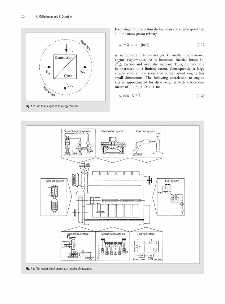
The technical system of a ‘‘diesel engine’’ is also part of awidely networked global system defined by the concepts of‘‘resources’’ and ‘‘environmental pollution’’. A view based purelyon energy and economics aimed at minimizing the losses SEV
fails to satisfy present day demands specified by the ecologicalimperative according to which energy and material must alwaysbe converted with maximum efficiency while minimally pollut-ing the environment. The outcome of the complex research anddevelopment work made necessary by these demands is thediesel engine of our day, which has evolved from a simple engineinto a complex engine system consisting of a number of sub-systems (Fig. 1-8). The increased integration of electrical andelectronic components and the transition from open controlsystems to closed control loops are characteristic of this devel-opment. Moreover, international competition is making mini-mum manufacturing costs and material consumption impera-tive. Among other things, this requires fit-for-purpose designsthat optimally utilize components.
1.2.2 Basic Engineering Data
Every reciprocating engine’s geometry and kinematics areclearly specified by the geometric parameters of the:– stroke/bore ratio z ¼ s/D,– connecting rod ratio lPl ¼ r/l and– compression ratio e ¼ Vmax/Vmin ¼ (Vc þ Vh)/Vc.
250
200
150
50
0
0.0 0.2 0.4 0.6 0.8
Volume V
Pre
ssur
e P
m3
100
at
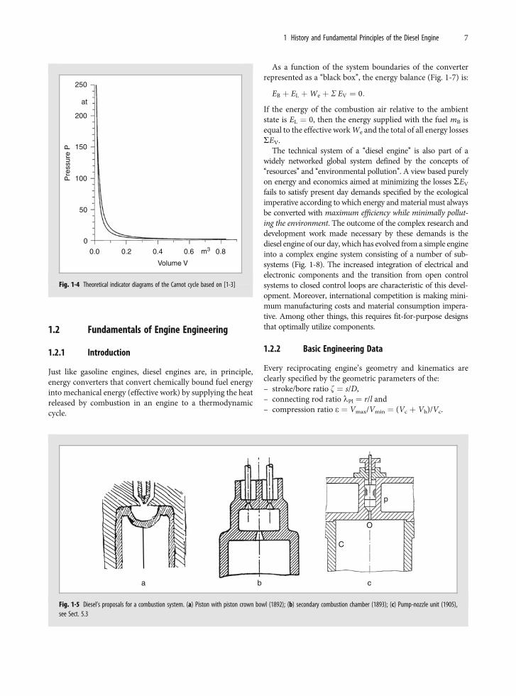
Fig. 1-4 Theoretical indicator diagrams of the Carnot cycle based on [1-3]
a b c
C
O
p
Fig. 1-5 Diesel’s proposals for a combustion system. (a) Piston with piston crown bowl (1892); (b) secondary combustion chamber (1893); (c) Pump-nozzle unit (1905),see Sect. 5.3
1 History and Fundamental Principles of the Diesel Engine 7
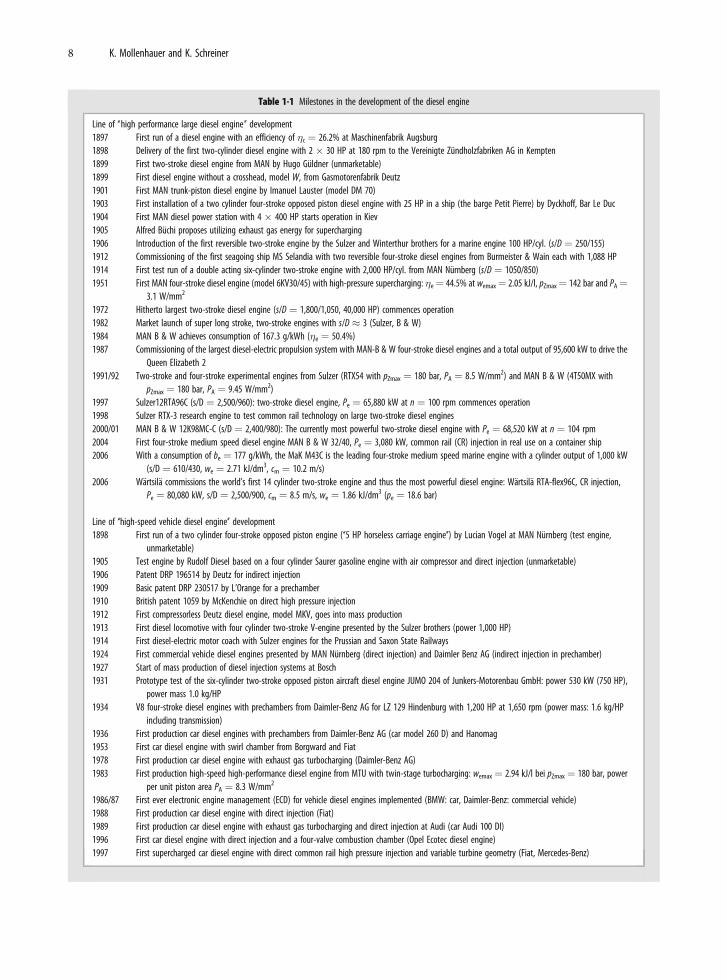
Table 1-1 Milestones in the development of the diesel engine
Line of ‘‘high performance large diesel engine’’ development1897 First run of a diesel engine with an efficiency of �c ¼ 26.2% at Maschinenfabrik Augsburg1898 Delivery of the first two-cylinder diesel engine with 2 � 30 HP at 180 rpm to the Vereinigte Zundholzfabriken AG in Kempten1899 First two-stroke diesel engine from MAN by Hugo Guldner (unmarketable)1899 First diesel engine without a crosshead, model W, from Gasmotorenfabrik Deutz1901 First MAN trunk-piston diesel engine by Imanuel Lauster (model DM 70)1903 First installation of a two cylinder four-stroke opposed piston diesel engine with 25 HP in a ship (the barge Petit Pierre) by Dyckhoff, Bar Le Duc1904 First MAN diesel power station with 4 � 400 HP starts operation in Kiev1905 Alfred Buchi proposes utilizing exhaust gas energy for supercharging1906 Introduction of the first reversible two-stroke engine by the Sulzer and Winterthur brothers for a marine engine 100 HP/cyl. (s/D ¼ 250/155)1912 Commissioning of the first seagoing ship MS Selandia with two reversible four-stroke diesel engines from Burmeister & Wain each with 1,088 HP1914 First test run of a double acting six-cylinder two-stroke engine with 2,000 HP/cyl. from MAN Nurnberg (s/D ¼ 1050/850)1951 First MAN four-stroke diesel engine (model 6KV30/45) with high-pressure supercharging: �e¼ 44.5% at wemax¼ 2.05 kJ/l, pZmax¼ 142 bar and PA¼
3.1 W/mm2
1972 Hitherto largest two-stroke diesel engine (s/D ¼ 1,800/1,050, 40,000 HP) commences operation1982 Market launch of super long stroke, two-stroke engines with s/D � 3 (Sulzer, B & W)1984 MAN B & W achieves consumption of 167.3 g/kWh (�e ¼ 50.4%)1987 Commissioning of the largest diesel-electric propulsion system with MAN-B & W four-stroke diesel engines and a total output of 95,600 kW to drive the
Queen Elizabeth 21991/92 Two-stroke and four-stroke experimental engines from Sulzer (RTX54 with pZmax ¼ 180 bar, PA ¼ 8.5 W/mm2) and MAN B & W (4T50MX with
pZmax ¼ 180 bar, PA ¼ 9.45 W/mm2)1997 Sulzer12RTA96C (s/D ¼ 2,500/960): two-stroke diesel engine, Pe ¼ 65,880 kW at n ¼ 100 rpm commences operation1998 Sulzer RTX-3 research engine to test common rail technology on large two-stroke diesel engines2000/01 MAN B & W 12K98MC-C (s/D ¼ 2,400/980): The currently most powerful two-stroke diesel engine with Pe ¼ 68,520 kW at n ¼ 104 rpm2004 First four-stroke medium speed diesel engine MAN B & W 32/40, Pe ¼ 3,080 kW, common rail (CR) injection in real use on a container ship2006 With a consumption of be ¼ 177 g/kWh, the MaK M43C is the leading four-stroke medium speed marine engine with a cylinder output of 1,000 kW
(s/D ¼ 610/430, we ¼ 2.71 kJ/dm3, cm ¼ 10.2 m/s)2006 Wartsila commissions the world’s first 14 cylinder two-stroke engine and thus the most powerful diesel engine: Wartsila RTA-flex96C, CR injection,
Pe ¼ 80,080 kW, s/D ¼ 2,500/900, cm ¼ 8.5 m/s, we ¼ 1.86 kJ/dm3 (pe ¼ 18.6 bar)
Line of ‘‘high-speed vehicle diesel engine’’ development1898 First run of a two cylinder four-stroke opposed piston engine (‘‘5 HP horseless carriage engine’’) by Lucian Vogel at MAN Nurnberg (test engine,
unmarketable)1905 Test engine by Rudolf Diesel based on a four cylinder Saurer gasoline engine with air compressor and direct injection (unmarketable)1906 Patent DRP 196514 by Deutz for indirect injection1909 Basic patent DRP 230517 by L’Orange for a prechamber1910 British patent 1059 by McKenchie on direct high pressure injection1912 First compressorless Deutz diesel engine, model MKV, goes into mass production1913 First diesel locomotive with four cylinder two-stroke V-engine presented by the Sulzer brothers (power 1,000 HP)1914 First diesel-electric motor coach with Sulzer engines for the Prussian and Saxon State Railways1924 First commercial vehicle diesel engines presented by MAN Nurnberg (direct injection) and Daimler Benz AG (indirect injection in prechamber)1927 Start of mass production of diesel injection systems at Bosch1931 Prototype test of the six-cylinder two-stroke opposed piston aircraft diesel engine JUMO 204 of Junkers-Motorenbau GmbH: power 530 kW (750 HP),
power mass 1.0 kg/HP1934 V8 four-stroke diesel engines with prechambers from Daimler-Benz AG for LZ 129 Hindenburg with 1,200 HP at 1,650 rpm (power mass: 1.6 kg/HP
including transmission)1936 First production car diesel engines with prechambers from Daimler-Benz AG (car model 260 D) and Hanomag1953 First car diesel engine with swirl chamber from Borgward and Fiat1978 First production car diesel engine with exhaust gas turbocharging (Daimler-Benz AG)1983 First production high-speed high-performance diesel engine from MTU with twin-stage turbocharging: wemax ¼ 2.94 kJ/l bei pZmax ¼ 180 bar, power
per unit piston area PA ¼ 8.3 W/mm2
1986/87 First ever electronic engine management (ECD) for vehicle diesel engines implemented (BMW: car, Daimler-Benz: commercial vehicle)1988 First production car diesel engine with direct injection (Fiat)1989 First production car diesel engine with exhaust gas turbocharging and direct injection at Audi (car Audi 100 DI)1996 First car diesel engine with direct injection and a four-valve combustion chamber (Opel Ecotec diesel engine)1997 First supercharged car diesel engine with direct common rail high pressure injection and variable turbine geometry (Fiat, Mercedes-Benz)
8 K. Mollenhauer and K. Schreiner
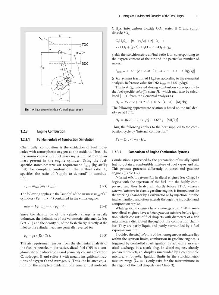
Vmin corresponds to the compression volume Vc and themaximum cylinder volume Vmax corresponds to the totalfrom Vc and the cylinder displacement Vh, to which thefollowing with the cylinder bore D and piston stroke s applies:
Vh ¼ s � p � D2=4:
Accordingly, VH ¼ z �Vh is the displacement of an enginewith z cylinders.
The trunk-piston engine (Fig. 1-9) has established itself.Only large two-stroke engines (see Sect. 18.4) have a cross-head drive to relieve the piston from cornering forces (seeSect. 8.1). Both types are still only used with a unilaterallyloaded piston. A standardized time value, the crank angle jand the rotational speed o have the following relationship:
o ¼ dj=dt ¼ 2 � p � n:
When the speed n is not denoted as engine speed (s–1) butrather, as is customary in engine manufacturing, in revolu-tions per minute (rpm), then o is ¼ p � n/30.
An internal combustion engine’s combustion cycle pro-ceeds in the hermetic cylinder volume Vz, which changesperiodically with the piston motion zK within the boundariesVmax and Vmin:
VzðjÞ ¼ Vc þ zKðjÞ � p � D2=4:
With the crank radius r as a function of the instantaneouscrank position j in crank angle degree (8CA) and top deadcenter TDC (j ¼ 0) as the starting point, the followingapplies to the piston stroke:
zK ¼ r � f ðjÞ;
The following approximation function is usually applied:
f ðjÞ ¼ 1� cosjþ ðlPl=4Þ � sin2 j:
The following ensues for instantaneous piston velocity cK andacceleration aK:
cK ¼ dzK=dt ¼ r � o � ½sinjþ ðlPl=2Þ � sin 2j�aK ¼ d2zK=dt2 ¼ �r � o � ½cosjþ lPL � cos 2j�:
Table 1-1 (Continued)
1998 First V8 car diesel engine: BMW 3.9 l DI turbodiesel, Pe ¼ 180 kW at 4,000 rpm, Mmax ¼ 560 Nm (1,750. . .2,500 rpm)1999 Smart cdi, 0.8 dm3 displacement, currently the smallest turbodiesel engine with intercooler and common rail high pressure injection: Pe ¼ 30 kW at
4,200 rpm with 3.4 l/100 km first ‘‘3 liter car’’ from DaimlerChrysler2000 First production car diesel engines with particulate filters (Peugeot)2004 OPEL introduces a Vectra OPC study suitable for everyday with a 1.9 liter CDTI twin turbo unit with a specific power output of PV ¼ 82 kW/dm3
2006 At the 74th 24 h Le Mans race, an AUDI R10 TDI with a V12 diesel engine (Pe > 476 kW at n ¼ 5,000 rpm, VH ¼ 5.5 dm3, we ¼ 2.1 kJ/dm3 with abiturbo boost pressure of pL ¼ 2.94 bar) wins the race
70
%
at
W/mm2300
250
200
150
100
50
0 0
1
2
3
4
5
6
7
60
50
40
30
20
10
01897
The
ory
The
ory
Net
effi
cien
cy η
e
Max
. cyl
inde
r pr
essu
re P
z m
ax
Pow
er p
er u
nit p
isto
n ar
ea P
A
1992 1897 1992 1897 1992
Fig. 1-6Optimum net efficiency �e, maximum cylinderpressure pZmax and power per unit piston areaPA for production engines approximately 100years after the introduction of the first dieselengine (see also Fig. 1-13 and Table 1-3)
1 History and Fundamental Principles of the Diesel Engine 9
Following from the piston stroke s in m and engine speed n ins�1, the mean piston velocity
cm ¼ 2 � s � n ½m=s� ð1-1Þ
is an important parameter for kinematic and dynamicengine performance. As it increases, inertial forces (�c2
m), friction and wear also increase. Thus, cm may onlybe increased to a limited extent. Consequently, a largeengine runs at low speeds or a high-speed engine hassmall dimensions. The following correlation to enginesize is approximated for diesel engines with a bore dia-meter of 0.1 m < D < 1 m:
cm � 8 � D�1=4: ð1-2Þ
Supercharging system
Exhaust system
Lubrication system Mechanical systems Cooling system
Oil coolingIntercooler
Fuel system
Combustion system Injection system
Fig. 1-8 The modern diesel engine as a complex of subsystems
Pollution
Resources
Cycle
Combustion
E
E W
L
eB
ΣEV
Fig. 1-7 The diesel engine as an energy converter
10 K. Mollenhauer and K. Schreiner
1.2.3 Engine Combustion
1.2.3.1 Fundamentals of Combustion Simulation
Chemically, combustion is the oxidation of fuel mole-cules with atmospheric oxygen as the oxidant. Thus, themaximum convertible fuel mass mB is limited by the airmass present in the engine cylinder. Using the fuel-specific stoichiometric air requirement Lmin (kg air/kgfuel) for complete combustion, the air/fuel ratio lV
specifies the ratio of ‘‘supply to demand’’ in combus-tion:
lv ¼ mLZ=ðmB � LminÞ: ð1-3Þ
The following applies to the ‘‘supply’’ of the air mass mLZ of allcylinders (VZ ¼ z � Vz) contained in the entire engine:
mLZ ¼ VZ � rZ ¼ ll � rL � VH: ð1-4Þ
Since the density rZ of the cylinder charge is usuallyunknown, the definitions of the volumetric efficiency ll (seeSect. 2.1) and the density rL of the fresh charge directly at theinlet to the cylinder head are generally reverted to:
rL ¼ pL=ðRL � TLÞ: ð1-5Þ
The air requirement ensues from the elemental analysis ofthe fuel: A petroleum derivative, diesel fuel (DF) is a con-glomerate of hydrocarbons and primarily consists of carbonC, hydrogen H and sulfur S with usually insignificant frac-tions of oxygen O and nitrogen N. Thus, the balance equa-tion for the complete oxidation of a generic fuel molecule
CxHySz into carbon dioxide CO2, water H2O and sulfurdioxide SO2
CxHySZ þ ½xþ ðy=2Þ þ z� � O2 !x � CO2 þ ðy=2Þ �H2Oþ z � SO2 þ Qex;
yields the stoichiometric air/fuel ratio Lmin corresponding tothe oxygen content of the air and the particular number ofmoles:
Lmin ¼ 11:48 � ðcþ 2:98 � hÞ þ 4:3 � s� 4:31 � o ½kg=kg�
(c, h, s, o: mass fraction of 1 kg fuel according to the elementalanalysis. Reference value for DK: Lmin ¼ 14.5 kg/kg).
The heat Qex released during combustion corresponds tothe fuel-specific calorific value Hu, which may also be calcu-lated [1-11] from the elemental analysis as:
Hu ¼ 35:2 � cþ 94:2 � hþ 10:5 � ðs� oÞ ½MJ=kg�The following approximate relation is based on the fuel den-sity rB at 158C:
Hu ¼ 46:22� 9:13 � r2B þ 3:68rB ½MJ=kg�:
Thus, the following applies to the heat supplied to the com-bustion cycle by ‘‘internal combustion’’:
EB ¼ Qzu � mB � Hu:
1.2.3.2 Comparison of Engine Combustion Systems
Combustion is preceded by the preparation of usually liquidfuel to obtain a combustible mixture of fuel vapor and air.This process proceeds differently in diesel and gasolineengines (Table 1-2).
Internal mixture formation in diesel engines (see Chap. 3)begins with the injection of the fuel into the highly com-pressed and thus heated air shortly before TDC, whereasexternal mixture in classic gasoline engines is formed outsidethe working chamber by a carburetor or by injection into theintake manifold and often extends through the induction andcompression stroke.
While gasoline engines have a homogeneous fuel/air mix-ture, diesel engines have a heterogeneous mixture before igni-tion, which consists of fuel droplets with diameters of a fewmicrometers distributed throughout the combustion cham-ber. They are partly liquid and partly surrounded by a fuelvapor/air mixture.
Provided the air/fuel ratio of the homogeneous mixture lieswithin the ignition limits, combustion in gasoline engines istriggered by controlled spark ignition by activating an elec-trical discharge in a spark plug. In diesel engines, alreadyprepared droplets, i.e. droplets surrounded by a combustiblemixture, auto-ignite. Ignition limits in the stoichiometricmixture range (lV ¼ 1) only exist for the micromixture inthe region of the fuel droplets (see Chap. 3).
Vc
Zk
D
TDC
BDC
s = 2r
2r
ϕl
Fig. 1-9 Basic engineering data of a trunk-piston engine
1 History and Fundamental Principles of the Diesel Engine 11
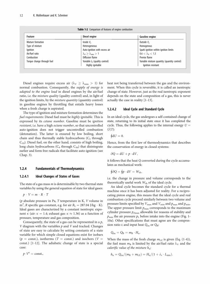
Diesel engines require excess air (lV lmin > 1) fornormal combustion. Consequently, the supply of energy isadapted to the engine load in diesel engines by the air/fuelratio, i.e. the mixture quality (quality control) and, in light ofthe ignition limits, by the mixture quantity (quantity control)in gasoline engines by throttling that entails heavy losseswhen a fresh charge is aspirated.
The type of ignition and mixture formation determines thefuel requirements: Diesel fuel must be highly ignitable. This isexpressed by its cetane number. Gasoline must be ignitionresistant, i.e. have a high octane number, so that uncontrolledauto-ignition does not trigger uncontrolled combustion(detonation). The latter is ensured by low boiling, shortchain and thus thermally stable hydrocarbons (C5 throughC10). Diesel fuel, on the other hand, consists of high boiling,long chain hydrocarbons (C9 through C30) that disintegrateearlier and form free radicals that facilitate auto-ignition (seeChap. 3).
1.2.4 Fundamentals of Thermodynamics
1.2.4.1 Ideal Changes of States of Gases
The state of a gas mass m is determinable by two thermal statevariables by using the general equation of state for ideal gases:
p � V ¼ m � R � T
(p absolute pressure in Pa, T temperature in K, V volume inm3, R specific gas constant, e.g. for air RL ¼ 287.04 J/kg � K).Ideal gases are characterized by a constant isentropic expo-nent k (air: k ¼ 1.4; exhaust gas: k � 1.36) as a function ofpressure, temperature and gas composition.
Consequently, the state of a gas can be represented in a p,V diagram with the variables p and V and tracked. Changesof state are easy to calculate by setting constants of a statevariable for which simple closed equations exist for isobars(p ¼ const.), isotherms (T ¼ const.) and isochors (V ¼const.) [1-12]. The adiabatic change of state is a specialcase:
p �Vk ¼ const.,
heat not being transferred between the gas and the environ-ment. When this cycle is reversible, it is called an isentropicchange of state. However, just as the real isentropic exponentdepends on the state and composition of a gas, this is neveractually the case in reality [1-13].
1.2.4.2 Ideal Cycle and Standard Cycle
In an ideal cycle, the gas undergoes a self-contained change ofstate, returning to its initial state once it has completed thecycle. Thus, the following applies to the internal energy U ¼U(T):
"dU ¼ 0:
Hence, from the first law of thermodynamics that describesthe conservation of energy in closed systems:
@Q ¼ dU þ p � dV;
it follows that the heat Q converted during the cycle accumu-lates as mechanical work:
"@Q ¼ "p � dV ¼Wth;
i.e. the change in pressure and volume corresponds to thetheoretically useful work Wth of the ideal cycle.
An ideal cycle becomes the standard cycle for a thermalmachine once it has been adjusted for reality. For a recipro-cating piston engine, this means that the ideal cycle and realcombustion cycle proceed similarly between two volume andpressure limits specified by Vmax and Vmin and pmax and pmin.The upper pressure limit pmax corresponds to the maximumcylinder pressure pZmax allowable for reasons of stability andpmin the air pressure pL before intake into the engine (Fig. 1-10a). Other specifications that must agree are the compres-sion ratio e and input heat Qzu or QB:
Qzu ¼ QB ¼ mB � Hu:
When the mass of the fresh charge mLZ is given (Eq. (1-4)),the fuel mass mB is limited by the air/fuel ratio lV and thecalorific value of the mixture hu:
hu ¼ Qzu=ðmB þmLZÞ ¼ Hu=ð1þ lv � LminÞ:
Table 1-2 Comparison of features of engine combustion
Feature Diesel engine Gasoline engine
Mixture formation Inside Vz Outside Vz
Type of mixture Heterogeneous HomogenousIgnition Auto-ignition with excess air Spark ignition within ignition limitsAir/fuel ratio lV lmin > 1 0.6 < lV < 1.3Combustion Diffusion flame Premix flameTorque change through fuel Variable lV (quality control)
Highly ignitableVariable mixture quantity (quantity control)
Ignition resistant
12 K. Mollenhauer and K. Schreiner
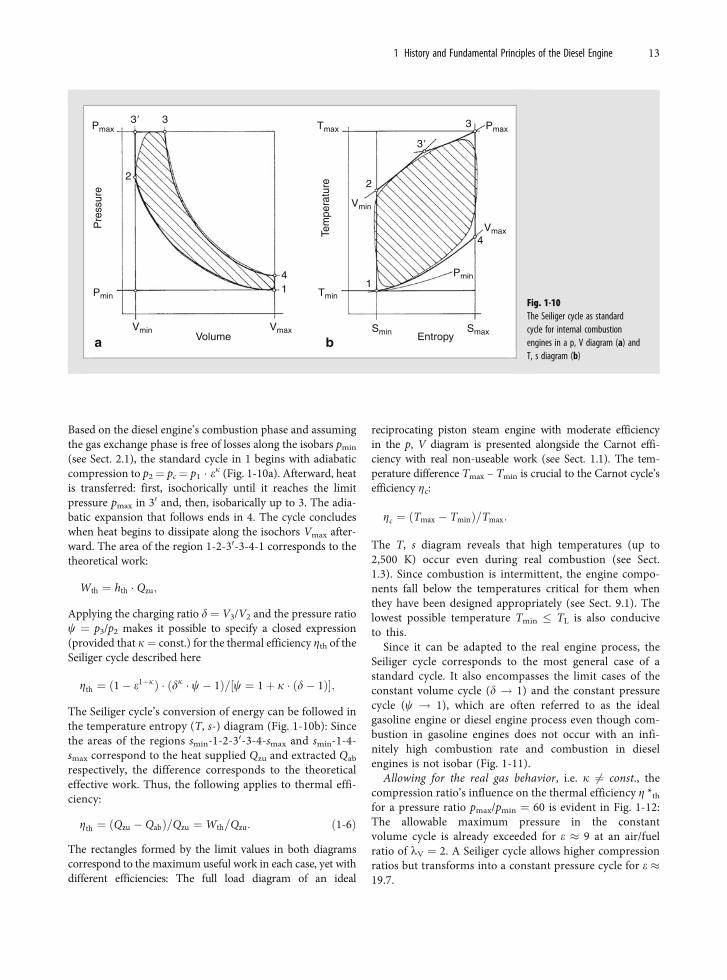
Based on the diesel engine’s combustion phase and assumingthe gas exchange phase is free of losses along the isobars pmin
(see Sect. 2.1), the standard cycle in 1 begins with adiabaticcompression to p2¼ pc¼ p1 � ek (Fig. 1-10a). Afterward, heatis transferred: first, isochorically until it reaches the limitpressure pmax in 30 and, then, isobarically up to 3. The adia-batic expansion that follows ends in 4. The cycle concludeswhen heat begins to dissipate along the isochors Vmax after-ward. The area of the region 1-2-30-3-4-1 corresponds to thetheoretical work:
Wth ¼ hth � Qzu;
Applying the charging ratio d ¼ V3/V2 and the pressure ratioc ¼ p3/p2 makes it possible to specify a closed expression(provided that k¼ const.) for the thermal efficiency Zth of theSeiliger cycle described here
Zth ¼ ð1� e1�kÞ � ðdk � c� 1Þ=½c ¼ 1þ k � ðd� 1Þ�;
The Seiliger cycle’s conversion of energy can be followed inthe temperature entropy (T, s-) diagram (Fig. 1-10b): Sincethe areas of the regions smin-1-2-30-3-4-smax and smin-1-4-smax correspond to the heat supplied Qzu and extracted Qab
respectively, the difference corresponds to the theoreticaleffective work. Thus, the following applies to thermal effi-ciency:
Zth ¼ ðQzu � QabÞ=Qzu ¼Wth=Qzu: ð1-6Þ
The rectangles formed by the limit values in both diagramscorrespond to the maximum useful work in each case, yet withdifferent efficiencies: The full load diagram of an ideal
reciprocating piston steam engine with moderate efficiencyin the p, V diagram is presented alongside the Carnot effi-ciency with real non-useable work (see Sect. 1.1). The tem-perature difference Tmax – Tmin is crucial to the Carnot cycle’sefficiency Zc:
Zc ¼ ðTmax � TminÞ=Tmax:
The T, s diagram reveals that high temperatures (up to2,500 K) occur even during real combustion (see Sect.1.3). Since combustion is intermittent, the engine compo-nents fall below the temperatures critical for them whenthey have been designed appropriately (see Sect. 9.1). Thelowest possible temperature Tmin � TL is also conduciveto this.
Since it can be adapted to the real engine process, theSeiliger cycle corresponds to the most general case of astandard cycle. It also encompasses the limit cases of theconstant volume cycle (d ! 1) and the constant pressurecycle (c ! 1), which are often referred to as the idealgasoline engine or diesel engine process even though com-bustion in gasoline engines does not occur with an infi-nitely high combustion rate and combustion in dieselengines is not isobar (Fig. 1-11).
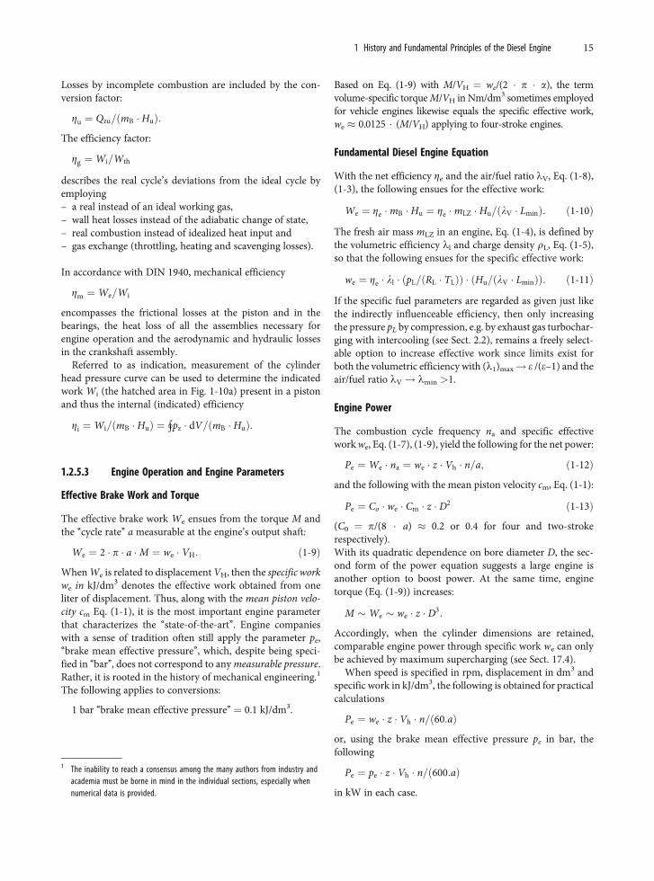
Allowing for the real gas behavior, i.e. k 6¼ const., thecompression ratio’s influence on the thermal efficiency Z *th
for a pressure ratio pmax/pmin ¼ 60 is evident in Fig. 1-12:The allowable maximum pressure in the constantvolume cycle is already exceeded for e � 9 at an air/fuelratio of lV ¼ 2. A Seiliger cycle allows higher compressionratios but transforms into a constant pressure cycle for e �19.7.
Pre
ssur
e
Pmax Pmax
Vmin
Vmin
Vmax
Vmax
SmaxEntropySminVolume
3�
3�
3
4
2
3
4
11
2
Pmin
Pmin
Tem
pera
ture
Tmax
Tmin
a b
Fig. 1-10The Seiliger cycle as standardcycle for internal combustionengines in a p, V diagram (a) andT, s diagram (b)
1 History and Fundamental Principles of the Diesel Engine 13
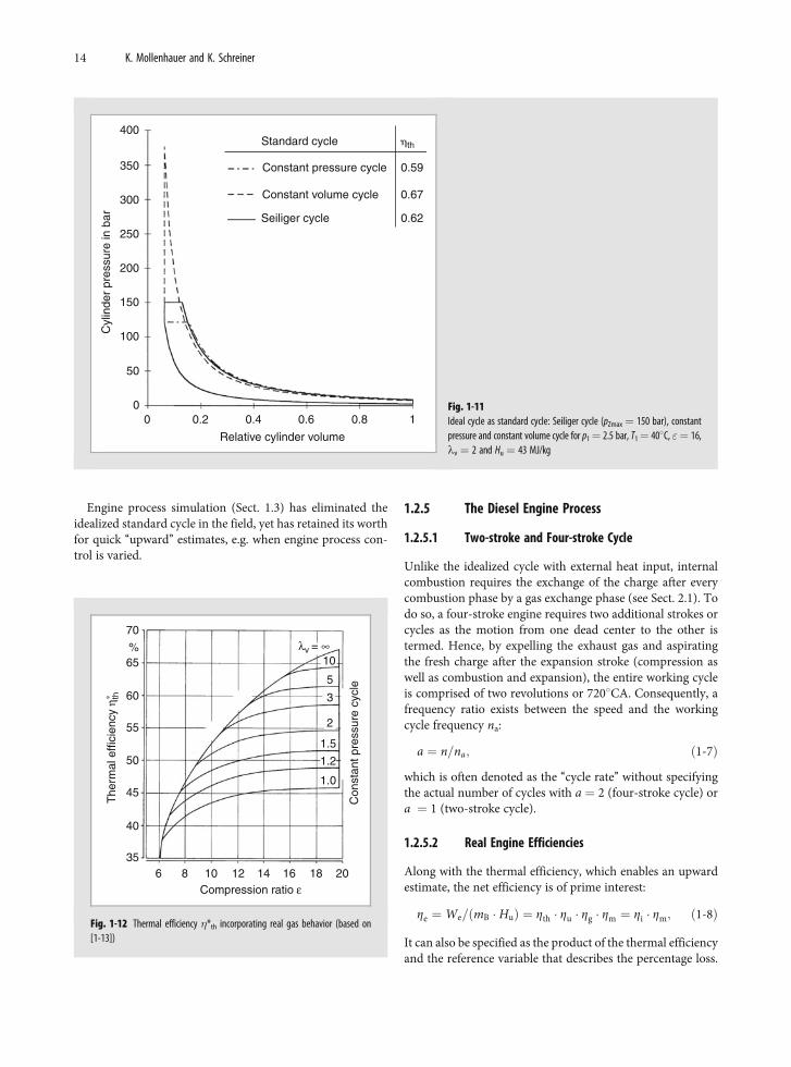
Engine process simulation (Sect. 1.3) has eliminated theidealized standard cycle in the field, yet has retained its worthfor quick ‘‘upward’’ estimates, e.g. when engine process con-trol is varied.
1.2.5 The Diesel Engine Process
1.2.5.1 Two-stroke and Four-stroke Cycle
Unlike the idealized cycle with external heat input, internalcombustion requires the exchange of the charge after everycombustion phase by a gas exchange phase (see Sect. 2.1). Todo so, a four-stroke engine requires two additional strokes orcycles as the motion from one dead center to the other istermed. Hence, by expelling the exhaust gas and aspiratingthe fresh charge after the expansion stroke (compression aswell as combustion and expansion), the entire working cycleis comprised of two revolutions or 7208CA. Consequently, afrequency ratio exists between the speed and the workingcycle frequency na:
a ¼ n=na; ð1-7Þ
which is often denoted as the ‘‘cycle rate’’ without specifyingthe actual number of cycles with a ¼ 2 (four-stroke cycle) ora ¼ 1 (two-stroke cycle).
1.2.5.2 Real Engine Efficiencies
Along with the thermal efficiency, which enables an upwardestimate, the net efficiency is of prime interest:
Ze ¼We=ðmB � HuÞ ¼ Zth � Zu � Zg � Zm ¼ Zi � Zm; ð1-8Þ
It can also be specified as the product of the thermal efficiencyand the reference variable that describes the percentage loss.
Compression ratio ε6 8 10
35
40
45
50
55
60
65%
70
12 14 16 18 20
1.0
1.2
1.5
2
3
5
10
The
rmal
effi
cien
cy η
∗ th
λv = ∞
Con
stan
t pre
ssur
e cy
cle
Fig. 1-12 Thermal efficiency �*th incorporating real gas behavior (based on[1-13])
400
350
300
250
200
150
100
50
00 0.2 0.4 0.6 0.8 1
Relative cylinder volume
Standard cycle �th
Constant volume cycle
Seiliger cycle
Constant pressure cycle 0.59
0.67
0.62
Cyl
inde
r pr
essu
re in
bar
Fig. 1-11Ideal cycle as standard cycle: Seiliger cycle (pZmax ¼ 150 bar), constantpressure and constant volume cycle for p1¼ 2.5 bar, T1¼ 408C, "¼ 16,lv ¼ 2 and Hu ¼ 43 MJ/kg
14 K. Mollenhauer and K. Schreiner
Losses by incomplete combustion are included by the con-version factor:
Zu ¼ Qzu=ðmB � HuÞ:
The efficiency factor:
Zg ¼Wi=Wth
describes the real cycle’s deviations from the ideal cycle byemploying– a real instead of an ideal working gas,– wall heat losses instead of the adiabatic change of state,– real combustion instead of idealized heat input and– gas exchange (throttling, heating and scavenging losses).
In accordance with DIN 1940, mechanical efficiency
Zm ¼We=Wi
encompasses the frictional losses at the piston and in thebearings, the heat loss of all the assemblies necessary forengine operation and the aerodynamic and hydraulic lossesin the crankshaft assembly.
Referred to as indication, measurement of the cylinderhead pressure curve can be used to determine the indicatedwork Wi (the hatched area in Fig. 1-10a) present in a pistonand thus the internal (indicated) efficiency
Zi ¼Wi=ðmB � HuÞ ¼ "pz � dV=ðmB � HuÞ:
1.2.5.3 Engine Operation and Engine Parameters
Effective Brake Work and Torque
The effective brake work We ensues from the torque M andthe ‘‘cycle rate’’ a measurable at the engine’s output shaft:
We ¼ 2 � p � a �M ¼ we � VH: ð1-9Þ
When We is related to displacement VH, then the specific workwe in kJ/dm3 denotes the effective work obtained from oneliter of displacement. Thus, along with the mean piston velo-city cm Eq. (1-1), it is the most important engine parameterthat characterizes the ‘‘state-of-the-art’’. Engine companieswith a sense of tradition often still apply the parameter pe,‘‘brake mean effective pressure’’, which, despite being speci-fied in ‘‘bar’’, does not correspond to any measurable pressure.Rather, it is rooted in the history of mechanical engineering.1
The following applies to conversions:
1 bar ‘‘brake mean effective pressure’’ ¼ 0.1 kJ/dm3.
Based on Eq. (1-9) with M/VH ¼ we/(2 � p � a), the termvolume-specific torque M/VH in Nm/dm3 sometimes employedfor vehicle engines likewise equals the specific effective work,we � 0.0125 � (M/VH) applying to four-stroke engines.
Fundamental Diesel Engine Equation
With the net efficiency Ze and the air/fuel ratio lV, Eq. (1-8),(1-3), the following ensues for the effective work:
We ¼ Ze �mB � Hu ¼ Ze �mLZ � Hu=ðlV � LminÞ: ð1-10Þ
The fresh air mass mLZ in an engine, Eq. (1-4), is defined bythe volumetric efficiency ll and charge density rL, Eq. (1-5),so that the following ensues for the specific effective work:
we ¼ Ze � ll � ðpL=ðRL � TLÞÞ � ðHu=ðlV � LminÞÞ: ð1-11Þ
If the specific fuel parameters are regarded as given just likethe indirectly influenceable efficiency, then only increasingthe pressure pL by compression, e.g. by exhaust gas turbochar-ging with intercooling (see Sect. 2.2), remains a freely select-able option to increase effective work since limits exist forboth the volumetric efficiency with (l1)max! e /(e–1) and theair/fuel ratio lV! lmin >1.
Engine Power
The combustion cycle frequency na and specific effectivework we, Eq. (1-7), (1-9), yield the following for the net power:
Pe ¼We � na ¼ we � z � Vh � n=a; ð1-12Þ
and the following with the mean piston velocity cm, Eq. (1-1):
Pe ¼ Co � we � Cm � z � D2 ð1-13Þ
(C0 ¼ p/(8 � a) � 0.2 or 0.4 for four and two-strokerespectively).With its quadratic dependence on bore diameter D, the sec-ond form of the power equation suggests a large engine isanother option to boost power. At the same time, enginetorque (Eq. (1-9)) increases:
M �We � we � z � D3:
Accordingly, when the cylinder dimensions are retained,comparable engine power through specific work we can onlybe achieved by maximum supercharging (see Sect. 17.4).
When speed is specified in rpm, displacement in dm3 andspecific work in kJ/dm3, the following is obtained for practicalcalculations
Pe ¼ we � z � Vh � n=ð60:aÞ
or, using the brake mean effective pressure pe in bar, thefollowing
Pe ¼ pe � z � Vh � n=ð600:aÞ
in kW in each case.
1 The inability to reach a consensus among the many authors from industry andacademia must be borne in mind in the individual sections, especially whennumerical data is provided.
1 History and Fundamental Principles of the Diesel Engine 15
The fundamental diesel engine equation, Eq. (1-11),reveals that engine power is a function of the ambientcondition: A diesel engine run at an altitude of 1,000 mcannot produce the same power as at sea level. Hence, setreference conditions (x) for performance comparisons andacceptance tests for users’ specific concerns have beendefined to convert the power P measured into the powerPx applicable to the reference condition.2 Generally, thefollowing applies:
Px ffi ab � P:
In addition to air pressure and temperature, influencingvariables for a and b are relative humidity, coolant inlettemperature in the intercooler and engine mechanical effi-ciency (Zm ¼ 0.8 if unknown). Since a danger of overcom-pensation has been proven to often exist, some vehicleengine manufacturers have switched to measuring powerin air conditioned test benches with ambient conditionsthat conform to standards. Since diesel engines have lowoverload capacity, the blocked ISO net power that may notbe exceeded or the ISO standard power that may beexceeded depending on the engines’ use is specified withthe defined magnitude and duration of their extra power[1-14]. At 10% overload, it corresponds to the CIMACrecommendation for ‘‘continuous brake power’’ for marineengines.
Power-Related Engine Parameters
Frequently applied to vehicle engines, the displacement spe-cific power output
PV ¼ Pe=VH ¼ we � n=a: ð1-14Þ
is a function of the speed and thus also engine size. On theother hand, the specific power per unit piston area:
PA ¼ Pe=ðz � AkÞ ¼ we � cm=ð2 � aÞ; ð1-15Þ
(with we in kJ/dm3, cm in m/s, 2 � a ¼ 4 results for a four-stroke engine and 2 � a¼ 2 for a two-stroke engine, where PA
is in W/mm2) is independent of engine size if the correlationfrom Eq. (1-2) is disregarded this once. The product ofmechanical and thermal (we) as well as dynamic load (cm)characterizes the ‘‘state-of-the-art’’ for two-stroke or four-stroke engines and large or vehicle engines in equal measureas the following example makes clear:
In a comparison of two production engines, the low speedtwo-stroke Wartsila RT96C diesel engine [1-15] with anMCR cylinder output of 5,720 kW, specific effective work ofwe ¼ 1.86 kJ/dm3 and a mean piston velocity of cm ¼ 8.5 m/sand the currently most powerful BMW diesel engine for cars
(BMW 306 D4: we ¼ 1.91 kJ/dm3, cm ¼ 13.2 m/s [1-16]), thefollowing ensues for the power per unit piston area anddisplacement specific power output:– Wartsila PA ¼ 7.91 W/mm2 and PV ¼ 3.16 kW/dm3,– BMW PA ¼ 6.31 W/mm2 and PV ¼ 70.2 kW/dm3.
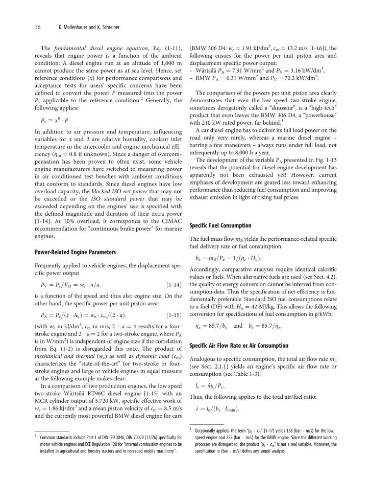
The comparison of the powers per unit piston area clearlydemonstrates that even the low speed two-stroke engine,sometimes derogatorily called a ‘‘dinosaur’’, is a ‘‘high-tech’’product that even leaves the BMW 306 D4, a ‘‘powerhouse’’with 210 kW rated power, far behind.3
A car diesel engine has to deliver its full load power on theroad only very rarely, whereas a marine diesel engine –barring a few maneuvers – always runs under full load, notinfrequently up to 8,000 h a year.
The development of the variable PA presented in Fig. 1-13reveals that the potential for diesel engine development hasapparently not been exhausted yet! However, currentemphases of development are geared less toward enhancingperformance than reducing fuel consumption and improvingexhaust emission in light of rising fuel prices.
Specific Fuel Consumption
The fuel mass flow m� B yields the performance-related specificfuel delivery rate or fuel consumption:
be ¼ _mB=Pe ¼ 1=ðZe � HuÞ:
Accordingly, comparative analyses require identical calorificvalues or fuels. When alternative fuels are used (see Sect. 4.2),the quality of energy conversion cannot be inferred from con-sumption data. Thus the specification of net efficiency is fun-damentally preferable. Standard ISO fuel consumptions relateto a fuel (DF) with Hu ¼ 42 MJ/kg. This allows the followingconversion for specifications of fuel consumption in g/kWh:
Ze ¼ 85:7=be and be ¼ 85:7=Ze:
Specific Air Flow Rate or Air Consumption
Analogous to specific consumption, the total air flow rate m� L
(see Sect. 2.1.1) yields an engine’s specific air flow rate orconsumption (see Table 1-3):
le ¼ _mL=Pe;
Thus, the following applies to the total air/fuel ratio:
l ¼ le=ðbe � LminÞ:
2 Common standards include Part 1 of DIN ISO 3046, DIN 70020 (11/76) specifically formotor vehicle engines and ECE Regulation 120 for ‘‘internal combustion engines to beinstalled in agricultural and forestry tractors and in non-road mobile machinery’’.
3 Occasionally applied, the term ‘‘pe � cm’’ [1-17] yields 158 (bar � m/s) for the lowspeed engine and 252 (bar � m/s) for the BMW engine. Since the different workingprocesses are disregarded, the product ‘‘pe � cm’’ is not a real variable. Moreover, thespecification in (bar � m/s) defies any sound analysis.
16 K. Mollenhauer and K. Schreiner
Engine Characteristic Map
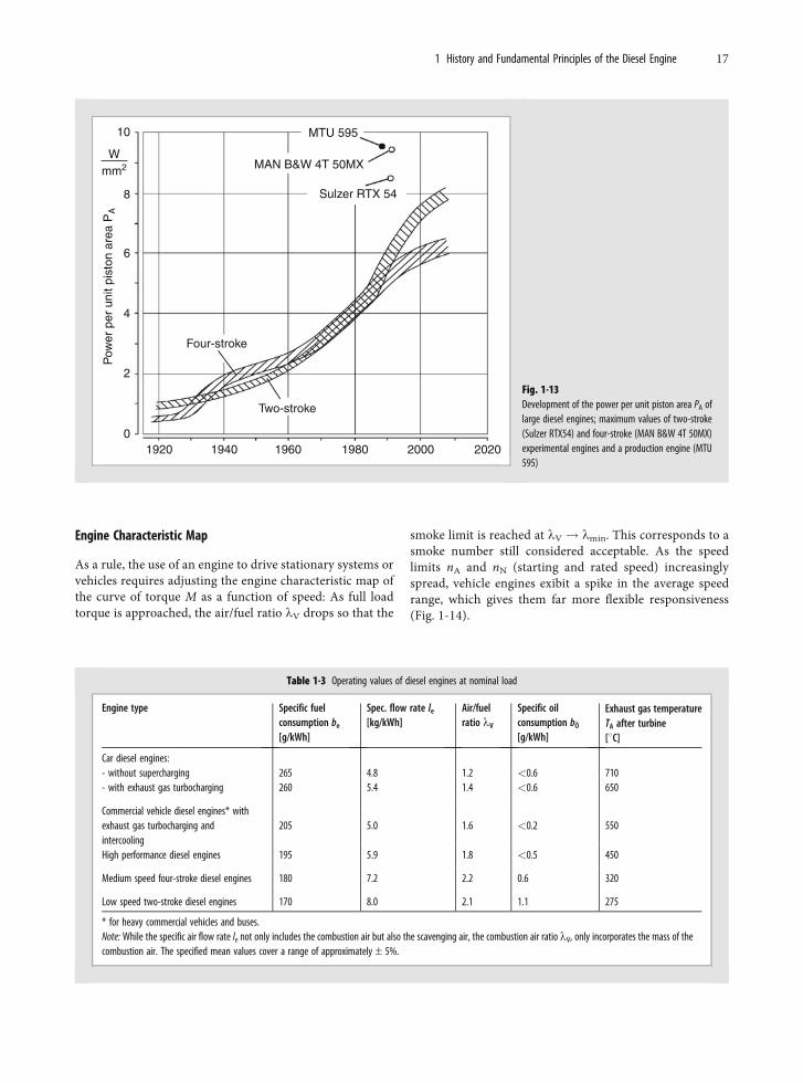
As a rule, the use of an engine to drive stationary systems orvehicles requires adjusting the engine characteristic map ofthe curve of torque M as a function of speed: As full loadtorque is approached, the air/fuel ratio lV drops so that the
smoke limit is reached at lV! lmin. This corresponds to asmoke number still considered acceptable. As the speedlimits nA and nN (starting and rated speed) increasinglyspread, vehicle engines exibit a spike in the average speedrange, which gives them far more flexible responsiveness(Fig. 1-14).
10
8
6
4
2
01920 1940 1960 1980 2000 2020
Two-stroke
Four-stroke
Sulzer RTX 54
MAN B&W 4T 50MX
MTU 595
Wmm2
Pow
er p
er u
nit p
isto
n ar
ea P
A
Fig. 1-13Development of the power per unit piston area PA oflarge diesel engines; maximum values of two-stroke(Sulzer RTX54) and four-stroke (MAN B&W 4T 50MX)experimental engines and a production engine (MTU595)
Table 1-3 Operating values of diesel engines at nominal load
Engine type Specific fuelconsumption be
[g/kWh]
Spec. flow rate le
[kg/kWh]Air/fuelratio lV
Specific oilconsumption bO
[g/kWh]
Exhaust gas temperatureTA after turbine[8C]
Car diesel engines:- without supercharging 265 4.8 1.2 <0.6 710- with exhaust gas turbocharging 260 5.4 1.4 <0.6 650
Commercial vehicle diesel engines* withexhaust gas turbocharging andintercooling
205 5.0 1.6 <0.2 550
High performance diesel engines 195 5.9 1.8 <0.5 450
Medium speed four-stroke diesel engines 180 7.2 2.2 0.6 320
Low speed two-stroke diesel engines 170 8.0 2.1 1.1 275
* for heavy commercial vehicles and buses.Note: While the specific air flow rate le not only includes the combustion air but also the scavenging air, the combustion air ratio lV, only incorporates the mass of thecombustion air. The specified mean values cover a range of approximately – 5%.
1 History and Fundamental Principles of the Diesel Engine 17
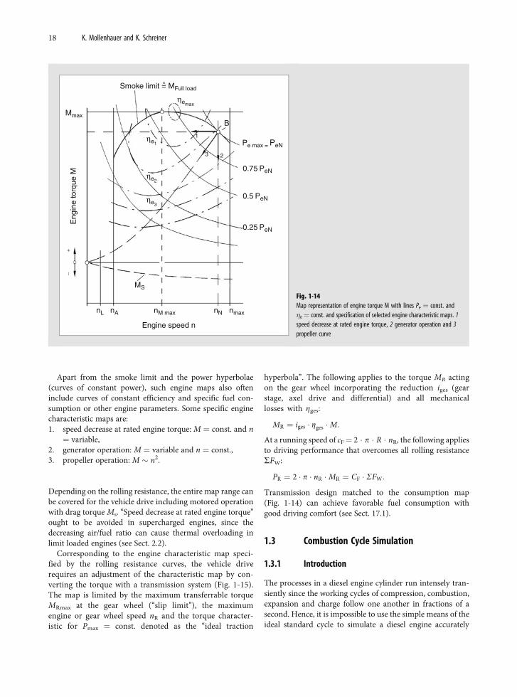
Apart from the smoke limit and the power hyperbolae(curves of constant power), such engine maps also ofteninclude curves of constant efficiency and specific fuel con-sumption or other engine parameters. Some specific enginecharacteristic maps are:1. speed decrease at rated engine torque: M ¼ const. and n¼ variable,
2. generator operation: M ¼ variable and n ¼ const.,3. propeller operation: M � n2.
Depending on the rolling resistance, the entire map range canbe covered for the vehicle drive including motored operationwith drag torque Ms. ‘‘Speed decrease at rated engine torque’’ought to be avoided in supercharged engines, since thedecreasing air/fuel ratio can cause thermal overloading inlimit loaded engines (see Sect. 2.2).
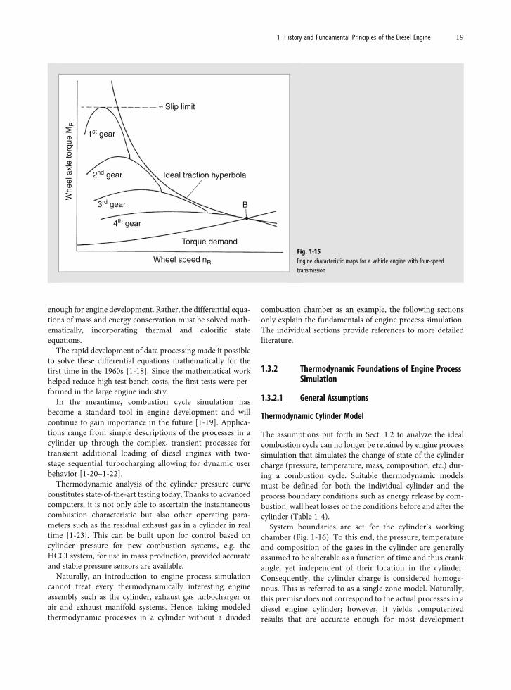
Corresponding to the engine characteristic map speci-fied by the rolling resistance curves, the vehicle driverequires an adjustment of the characteristic map by con-verting the torque with a transmission system (Fig. 1-15).The map is limited by the maximum transferrable torqueMRmax at the gear wheel (‘‘slip limit’’), the maximumengine or gear wheel speed nR and the torque character-istic for Pmax ¼ const. denoted as the ‘‘ideal traction
hyperbola’’. The following applies to the torque MR actingon the gear wheel incorporating the reduction iges (gearstage, axel drive and differential) and all mechanicallosses with Zges:
MR ¼ iges � Zges �M:
At a running speed of cF¼ 2 � p � R � nR, the following appliesto driving performance that overcomes all rolling resistanceSFW:
PR ¼ 2 � p � nR �MR ¼ CF � SFW:
Transmission design matched to the consumption map(Fig. 1-14) can achieve favorable fuel consumption withgood driving comfort (see Sect. 17.1).
1.3 Combustion Cycle Simulation
1.3.1 Introduction
The processes in a diesel engine cylinder run intensely tran-siently since the working cycles of compression, combustion,expansion and charge follow one another in fractions of asecond. Hence, it is impossible to use the simple means of theideal standard cycle to simulate a diesel engine accurately
Smoke limit = MFull load^
Mmax
nmaxnM max nNnAnL
MS
B
1
3 2
Eng
ine
torq
ue M
Engine speed n
Pe max = PeN
0.75 PeN
0.5 PeN
0.25 PeN
ηemax
ηe1
ηe2
ηe3
Fig. 1-14Map representation of engine torque M with lines Pe ¼ const. and�e¼ const. and specification of selected engine characteristic maps. 1speed decrease at rated engine torque, 2 generator operation and 3propeller curve
18 K. Mollenhauer and K. Schreiner
enough for engine development. Rather, the differential equa-tions of mass and energy conservation must be solved math-ematically, incorporating thermal and calorific stateequations.
The rapid development of data processing made it possibleto solve these differential equations mathematically for thefirst time in the 1960s [1-18]. Since the mathematical workhelped reduce high test bench costs, the first tests were per-formed in the large engine industry.
In the meantime, combustion cycle simulation hasbecome a standard tool in engine development and willcontinue to gain importance in the future [1-19]. Applica-tions range from simple descriptions of the processes in acylinder up through the complex, transient processes fortransient additional loading of diesel engines with two-stage sequential turbocharging allowing for dynamic userbehavior [1-20–1-22].
Thermodynamic analysis of the cylinder pressure curveconstitutes state-of-the-art testing today, Thanks to advancedcomputers, it is not only able to ascertain the instantaneouscombustion characteristic but also other operating para-meters such as the residual exhaust gas in a cylinder in realtime [1-23]. This can be built upon for control based oncylinder pressure for new combustion systems, e.g. theHCCI system, for use in mass production, provided accurateand stable pressure sensors are available.
Naturally, an introduction to engine process simulationcannot treat every thermodynamically interesting engineassembly such as the cylinder, exhaust gas turbocharger orair and exhaust manifold systems. Hence, taking modeledthermodynamic processes in a cylinder without a divided
combustion chamber as an example, the following sectionsonly explain the fundamentals of engine process simulation.The individual sections provide references to more detailedliterature.
1.3.2 Thermodynamic Foundations of Engine ProcessSimulation
1.3.2.1 General Assumptions
Thermodynamic Cylinder Model
The assumptions put forth in Sect. 1.2 to analyze the idealcombustion cycle can no longer be retained by engine processsimulation that simulates the change of state of the cylindercharge (pressure, temperature, mass, composition, etc.) dur-ing a combustion cycle. Suitable thermodynamic modelsmust be defined for both the individual cylinder and theprocess boundary conditions such as energy release by com-bustion, wall heat losses or the conditions before and after thecylinder (Table 1-4).
System boundaries are set for the cylinder’s workingchamber (Fig. 1-16). To this end, the pressure, temperatureand composition of the gases in the cylinder are generallyassumed to be alterable as a function of time and thus crankangle, yet independent of their location in the cylinder.Consequently, the cylinder charge is considered homoge-nous. This is referred to as a single zone model. Naturally,this premise does not correspond to the actual processes in adiesel engine cylinder; however, it yields computerizedresults that are accurate enough for most development
≈ Slip limit
1st gear
2nd gear
3rd gear
4th gear
Wheel speed nR
Torque demand
Ideal traction hyperbola
B
Whe
el a
xle
torq
ue M
R
Fig. 1-15Engine characteristic maps for a vehicle engine with four-speedtransmission
1 History and Fundamental Principles of the Diesel Engine 19
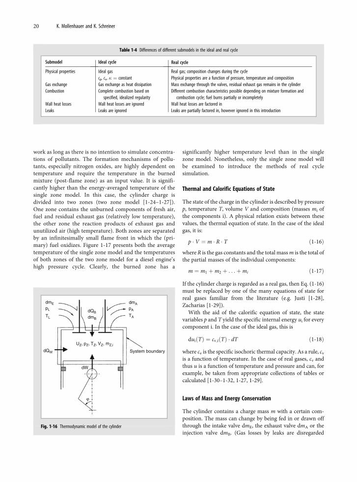
work as long as there is no intention to simulate concentra-tions of pollutants. The formation mechanisms of pollu-tants, especially nitrogen oxides, are highly dependent ontemperature and require the temperature in the burnedmixture (post-flame zone) as an input value. It is signifi-cantly higher than the energy-averaged temperature of thesingle zone model. In this case, the cylinder charge isdivided into two zones (two zone model [1-24–1-27]).One zone contains the unburned components of fresh air,fuel and residual exhaust gas (relatively low temperature),the other zone the reaction products of exhaust gas andunutilized air (high temperature). Both zones are separatedby an infinitesimally small flame front in which the (pri-mary) fuel oxidizes. Figure 1-17 presents both the averagetemperature of the single zone model and the temperaturesof both zones of the two zone model for a diesel engine’shigh pressure cycle. Clearly, the burned zone has a
significantly higher temperature level than in the singlezone model. Nonetheless, only the single zone model willbe examined to introduce the methods of real cyclesimulation.
Thermal and Calorific Equations of State
The state of the charge in the cylinder is described by pressurep, temperature T, volume V and composition (masses mi ofthe components i). A physical relation exists between thesevalues, the thermal equation of state. In the case of the idealgas, it is:
p � V ¼ m � R � T ð1-16Þ
where R is the gas constants and the total mass m is the total ofthe partial masses of the individual components:
m ¼ m1 þm2 þ . . .þmi ð1-17Þ
If the cylinder charge is regarded as a real gas, then Eq. (1-16)must be replaced by one of the many equations of state forreal gases familiar from the literature (e.g. Justi [1-28],Zacharias [1-29]).
With the aid of the calorific equation of state, the statevariables p and T yield the specific internal energy ui for everycomponent i. In the case of the ideal gas, this is
duiðTÞ ¼ cv;iðTÞ � dT ð1-18Þ
where cv is the specific isochoric thermal capacity. As a rule, cv
is a function of temperature. In the case of real gases, cv andthus u is a function of temperature and pressure and can, forexample, be taken from appropriate collections of tables orcalculated [1-30–1-32, 1-27, 1-29].
Laws of Mass and Energy Conservation
The cylinder contains a charge mass m with a certain com-position. The mass can change by being fed in or drawn offthrough the intake valve dmE, the exhaust valve dmA or theinjection valve dmB. (Gas losses by leaks are disregarded
Table 1-4 Differences of different submodels in the ideal and real cycle
Submodel Ideal cycle Real cycle
Physical properties Ideal gascp, cv, � ¼ constant
Real gas; composition changes during the cyclePhysical properties are a function of pressure, temperature and composition
Gas exchange Gas exchange as heat dissipation Mass exchange through the valves, residual exhaust gas remains in the cylinderCombustion Complete combustion based on
specified, idealized regularityDifferent combustion characteristics possible depending on mixture formation and
combustion cycle; fuel burns partially or incompletelyWall heat losses Wall heat losses are ignored Wall heat losses are factored inLeaks Leaks are ignored Leaks are partially factored in, however ignored in this introduction
System boundary
dmE
dQW
UZ, pZ, TZ, VZ, mZ,i
dW
ϕ
dQB
dmApA
TAdmB
pL
TL
Fig. 1-16 Thermodynamic model of the cylinder
20 K. Mollenhauer and K. Schreiner
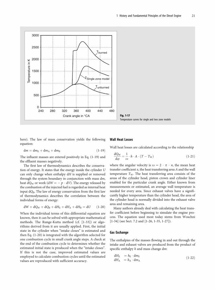
here). The law of mass conservation yields the followingequation:
dm ¼ dmE þ dmA þ dmB ð1-19Þ
The influent masses are entered positively in Eq. (1-19) andthe effluent masses negatively.
The first law of thermodynamics describes the conserva-tion of energy. It states that the energy inside the cylinder Ucan only change when enthalpy dH is supplied or removedthrough the system boundary in conjunction with mass dm,heat dQW or work (dW ¼ � p � dV). The energy released bythe combustion of the injected fuel is regarded as internal heatinput dQB. The law of energy conservation from the first lawof thermodynamics describes the correlation between theindividual forms of energy:
dWþ dQW þ dQB þ dHE þ dHA þ dHB ¼ dU ð1-20Þ
When the individual terms of this differential equation areknown, then it can be solved with appropriate mathematicalmethods. The Runge-Kutta method (cf. [1-33]) or algo-rithms derived from it are usually applied. First, the initialstate in the cylinder when ‘‘intake closes’’ is estimated andthen Eq. (1-20) is integrated with the algorithm selected forone combustion cycle in small crank angle steps. A check atthe end of the combustion cycle to determines whether theestimated initial state is produced when the ‘‘intake closes’’.If this is not the case, improved estimated values areemployed to calculate combustion cycles until the estimatedvalues are reproduced with sufficient accuracy.
Wall Heat Losses
Wall heat losses are calculated according to the relationship
dQW
dj¼ 1
o� h � A � ðT � TWÞ ð1-21Þ
where the angular velocity is o ¼ 2 � p � n, the mean heattransfer coefficient a, the heat transferring area A and the walltemperature TW. The heat transferring area consists of theareas of the cylinder head, piston crown and cylinder linerenabled for the particular crank angle. Either known frommeasurements or estimated, an average wall temperature isneeded for every area. Since exhaust valves have a signifi-cantly higher temperature than the cylinder head, the area ofthe cylinder head is normally divided into the exhaust valvearea and remaining area.
Many authors already deal with calculating the heat trans-fer coefficient before beginning to simulate the engine pro-cess. The equation used most today stems from Woschni[1-34] (see Sect. 7.2 and [1-26, 1-35, 1-27]).
Gas Exchange
The enthalpies of the masses flowing in and out through theintake and exhaust valves are produced from the product ofspecific enthalpy h and mass change dm:
dHE ¼ hE � dmE
dHA ¼ hA � dmAð1-22Þ
3000
2500
2000
1500
1000
500
0240 280 320 360 400 440 480
Crank angle in °CA
Tburned
Tunburned
TSingle zone model
Tem
pera
ture
in K
Fig. 1-17Temperature curves for single and two zone models
1 History and Fundamental Principles of the Diesel Engine 21