Embed Size (px)
Citation preview

MARCH 2017 KING AIR MAGAZINE • 1
MARCH 2017 • VOLUME 11, NUMBER 3 • $6.50 A MAGAZINE FOR THE OWNER/PILOT OF KING AIR AIRCRAFT
King Air Market ReviewAn Appraiser’s Assessment

2 • KING AIR MAGAZINE MARCH 2017

MARCH 2017 KING AIR MAGAZINE • 1
A MAGAZINE FOR THE OWNER/PILOT OF KING AIR AIRCRAFT
2
KingAir MARCH 2017 Volume 11 / Number 3
2 The King Air Market – An Appraiser’s Annual Review by Jim Becker
10 Pilot Speak: Facelift: Jeppesen SID/STAR Charts Having “A Little Work Done” by Matthew McDaniel
18 Aviation Issues: Recent News by Kim Blonigen
20 Ask the Expert: Ice Vanes: How Important Are They? by Tom Clements
24 Walter’s Wooden Wonder by Edward H. Phillips
29 Value Added
30 Technically...
32 Advertiser Index
Contents10 18 24
E D I T O R Kim Blonigen
E D I T O R I A L O F F I C E 2779 Aero Park Dr.,
Traverse City MI 49686 Phone: (316) 652-9495
E-mail: [email protected]
P U B L I S H E R S J. Scott Lizenby
Dave Moore Village Publications
G R A P H I C D E S I G N Luana Dueweke
P R O D U C T I O N M A N A G E R Mike Revard
P U B L I C A T I O N S D I R E C T O R Jason Smith
A D V E R T I S I N G D I R E C T O R John Shoemaker King Air Magazine
2779 Aero Park Drive Traverse City, MI 49686 Phone: 1-800-773-7798
Fax: (231) 946-9588 E-mail: [email protected]
A D V E R T I S I N G E X E C U T I V E A S S I S T A N T Betsy Beaudoin
Phone: 1-800-773-7798 E-mail: [email protected]
S U B S C R I B E R S E R V I C E S Rhonda Kelly, Mgr.
Diane Chauvin Molly Costilow Jamie Wilson
P.O. Box 1810 Traverse City, MI 49685
1-800-447-7367
O N L I N E A D D R E S S www.kingairmagazine.com
S U B S C R I P T I O N SKing Air is distributed at no charge to all registered owners of King Air aircraft. The mailing list is updated bi-monthly. All others may sub scribe by writing to: King Air, P.O. Box 1810, Traverse City, MI 49685, or by calling 1-800-447-7367. Rates for one year, 12 issues: United States $15.00, Canada $24.00 (U.S. funds), all other foreign $52.00 (U.S. funds). Single copies: United States $6.50, Canada/Foreign $9.00.
C O V E R P H O T O Photo courtesy of
Raisbeck Engineering
King Air is wholly owned by Village Press, Inc. and is in no way associated with or a product of Textron Aviation.
King Air (ISSN 1938-9361), USPS 16694 is published monthly by Village Press, Inc., 2779 Aero Park Drive, Traverse City, Michigan 49686. Periodicals Postage Paid at Traverse City, MI. POSTMASTER: Send address changes to King Air, Village Press Inc., P.O. Box 1810, Traverse City, MI 49685. Telephone (231) 946-3712. Printed in the United States of America. All rights reserved. Copyright 2017, Village Publications.
ADVERTISING: Advertising in King Air does not necessarily imply endorsement. Queries, questions, and requests for media kits should be directed to the Advertising Director, King Air, P.O. Box 1810, Traverse City, Michigan 49685. Telephone 1-800-773-7798.
MANUSCRIPTS: King Air assumes no responsibility for unsolicited manuscripts, photographs, or art work. While unsolicited submis-sions are welcome, it is best to query first and ask for our Writer’s Guidelines. All unassigned submissions must be accompanied by return postage. Address queries and requests for Writer’s Guidelines to the editor.

2 • KING AIR MAGAZINE MARCH 2017
by Jim Becker, Accredited Senior Appraiser
The KING AIR Market
MARCH 2017 KING AIR MAGAZINE • 3
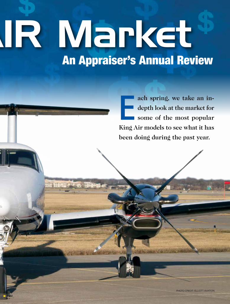
E ach spring, we take an in-
depth look at the market for
some of the most popular
King Air models to see what it has
been doing during the past year.
An Appraiser’s Annual Review
PHOTO CREDIT: ELLIOTT AVIATION
The KING AIR Market
4 • KING AIR MAGAZINE MARCH 2017
Because there are so many market types, in this article we will focus on only the variants that are still in production; specifically, the C90, the B200, and the King Air 350. We have been producing this market analysis for the past three years and have never focused on aftermarket modifications, as these can greatly affect the value of the aircraft. This year, however, we’d like to provide the information so that operators are aware of the popular modifications
available for aircraft customization. There is no hard and fast rule to determine how much value a modification adds to an aircraft. Many factors need to be taken into consideration, such as the popularity of the mod, time since installation, health of the overall market for that particular aircraft, and longevity
of the mod. Modifications such as engine upgrades and certain avionics upgrades seem to retain the most value. This is due to the fact that most operators like to go faster and want the latest electronic equipment.
Popular Modifications for All Models:Garmin G1000®
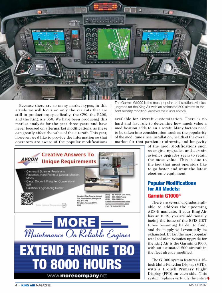
There are several upgrades avail- able to address the upcoming ADS-B mandate. If your King Air has an EFIS, you are additionally facing the issue of the EFIS CRT tubes becoming harder to find, and the supply will eventually be exhausted. By far, the most popular total solution avionics upgrade for the King Air is the Garmin G1000, with an estimated 500 aircraft in the fleet already modified.
The G1000 system features a 15-inch Multi-Function Display (MFD), with a 10-inch Primary Flight Display (PFD) on each side. This system replaces virtually the entire
The Garmin G1000 is the most popular total solution avionics upgrade for the King Air with an estimated 500 aircraft in the fleet already modified. (PHOTO CREDIT: ELLIOTT AVIATION)
�

MARCH 2017 KING AIR MAGAZINE • 5
6 • KING AIR MAGAZINE MARCH 2017
avionics suite, even replacing the radar and autopilot, significantly reducing your sustainment costs of the aircraft and avoiding obsolescence issues well into the next decade.
BLR WingletsAvailable for the C90, 200, and 300 series, BLR makes
a carbon fiber winglet that not only gives your King Air a more modern look, but also improves performance. With these winglets, you can expect reduced fuel burn, improved short field performance, extended range, and reduced time to climb. The reduced drag and fuel consumption can be five percent or more.
Raisbeck Modifications Available for All Models
Raisbeck has been modifying King Airs for decades. A mod available for all King Air models is wing lockers, which add external storage to the King Air by modifying
the existing nacelle and adding a fiberglass storage area. The lockers can each accommodate 300 lbs of cargo with a 17 cubic-foot capacity. Wing lockers have been standard on the 350 since 2004.
Another Raisbeck option available for all King Airs are the Dual Aft Body Strakes. According to Raisbeck, the strakes improve directional stability, passenger ride quality, pilot control and aircraft handling characteristics, and climb and cruise performance. These have been standard on the 350 since 2001.
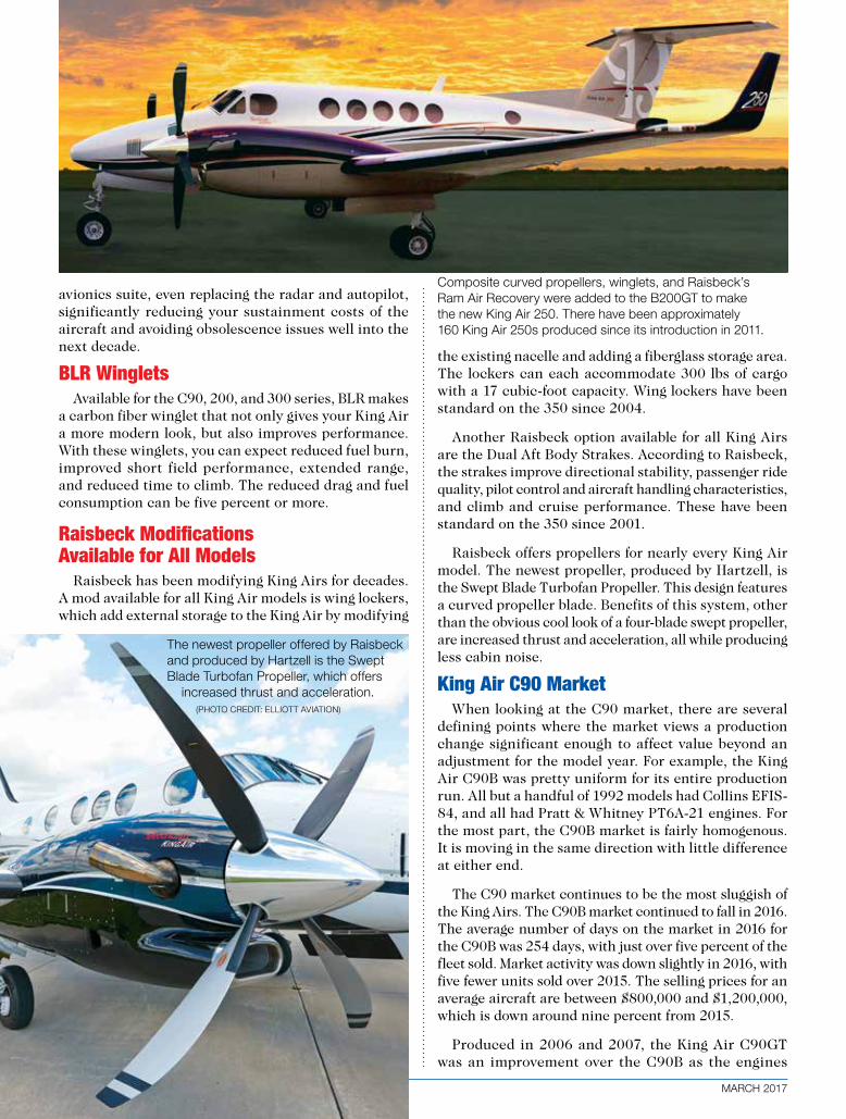
Raisbeck offers propellers for nearly every King Air model. The newest propeller, produced by Hartzell, is the Swept Blade Turbofan Propeller. This design features a curved propeller blade. Benefits of this system, other than the obvious cool look of a four-blade swept propeller, are increased thrust and acceleration, all while producing less cabin noise.
King Air C90 MarketWhen looking at the C90 market, there are several
defining points where the market views a production change significant enough to affect value beyond an adjustment for the model year. For example, the King Air C90B was pretty uniform for its entire production run. All but a handful of 1992 models had Collins EFIS-84, and all had Pratt & Whitney PT6A-21 engines. For the most part, the C90B market is fairly homogenous. It is moving in the same direction with little difference at either end.
The C90 market continues to be the most sluggish of the King Airs. The C90B market continued to fall in 2016. The average number of days on the market in 2016 for the C90B was 254 days, with just over five percent of the fleet sold. Market activity was down slightly in 2016, with five fewer units sold over 2015. The selling prices for an average aircraft are between $800,000 and $1,200,000, which is down around nine percent from 2015.
Produced in 2006 and 2007, the King Air C90GT was an improvement over the C90B as the engines
The newest propeller offered by Raisbeck and produced by Hartzell is the Swept Blade Turbofan Propeller, which offers increased thrust and acceleration. (PHOTO CREDIT: ELLIOTT AVIATION)
Composite curved propellers, winglets, and Raisbeck’s Ram Air Recovery were added to the B200GT to make the new King Air 250. There have been approximately 160 King Air 250s produced since its introduction in 2011.
MARCH 2017 KING AIR MAGAZINE • 7
were upgraded to Pratt & Whitney PT6A-135A models. This provided a nearly 30-knot increase in airspeed and created a distinct market segment within the 90 series. The C90GT segment is quite small, with only 98 models produced. Prices for an average aircraft range from approximately $1,450,000 to $1,500,000. The average hold time of a C90GT was 266 days, with just over 11 percent of the fleet selling in 2016. Seven C90GTs sold in 2016, which is an increase of four units when compared to 2015. The C90GT market appears to be weakening at this time, with a pricing decline of approximately 10 percent in 2016.
In 2008, Collins Pro Line 21 avionics were added and the C90GT was rebranded as the C90GTi. This further segmented the C90 market and created a large value difference between a 2007 and a 2008 model. The C90GTi production run consists of 125 aircraft. Eight units sold in 2016, representing six percent of the fleet. This is an increase from 2015, which saw five units sold. The average days on the market in 2016 was 168 days. Pricing for an average C90GTi range from approximately $1,600,000 to $1,700,000. Pricing dropped approximately 10 percent in 2016.
In 2010, Beechcraft added winglets and the C90GTi became the C90GTx, which is the most current version of the C90 and has a current production of around
150 aircraft. Ten pre-owned units sold in 2016, which represents 6.5 percent of the segment, and is an increase of four units over 2015. Average hold time was 220 days on the market. Pricing for a used C90GTx is between $1,800,000 to $2,400,000 for an average aircraft, which is off around 10 percent from 2015. The pricing on the used C90GTx is trending downward.
Engine Upgrades for the C90There are a couple of choices for engine upgrades
for the C90. Blackhawk offers an XP135A upgrade that provides an increased airspeed and reduced operating costs. GE Aviation offers the H17 engine, which boasts 750 shaft horsepower. This increases the cruise speed, while allowing for a reduced fuel burn. Another choice for both the C90 and F90 is the Pratt & Whitney PT6-135A engine. This engine is also rated at 750 shaft horsepower. Operators can expect a 20- to 30-knot increase in cruise speed for any of these engine upgrades.
King Air B200 MarketThe King Air B200 has enjoyed an amazing production
run with a basic aerodynamic design that has been largely unchanged for over 40 years. At first glance, it would be easy to group all the B200s together as one single market, however, they can be grouped into seven distinct submarkets.
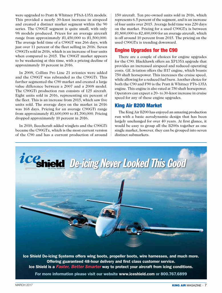
De-icing Never Looked This Good
Ice Shield De-icing Systems offers wing boots, propeller boots, wire harnesses, and much more. Offering guaranteed 48-hour delivery and first class customer service.
Ice Shield is a Faster, Better Smarter way to protect your aircraft from icing conditions.
For more information please visit our website www.iceshield.com or 800.767.6899
8 • KING AIR MAGAZINE MARCH 2017
The original B200 was an improved version of the King Air 200, produced from mid-year 1981 to 1984 and approximately 280 airframes are still in service. Out of these, 31 sold in 2016, making up around 11 percent of this segment. This is slightly more than the number that sold in 2015. Average number of days on the market for a 1981 to 1984 B200 was 228 days in 2016. Price for an average aircraft of this vintage is between $900,000 and $1,100,000, which for this segment is down slightly from last year, but remains fairly stable.
The next segment of the B200 market, produced in 1985 through 1993, contains roughly 250 aircraft that are still in service. In this section of the B200 market, improvements such as a hydraulic landing gear, three element wing spar, and triple fed electrical bus created a separate segment within the B200 market. Of these, there were 24 sales to retail customers in 2016, which is two fewer than what sold in this segment in 2015. This represents roughly nine percent of that segment. The average hold time for these models that sold was 191 days on the market. Expect to pay between $1,150,000 and $1,450,000. Pricing is down from last year around five percent.
For model year 1994, improvements such as a standard four-blade propeller and a cabin noise reduction system created another market segment and out of these, around 180 aircraft remain in service. Of these, 16 units sold to retail customers in 2016, which is an increase of five units over 2015, and represents nine percent of that segment. The average hold times for those aircraft that did sell was 120 days. Expect to pay between $1,500,000 and $1,700,000 for an aircraft of this vintage. Pricing in this segment has shown some softness in 2016 with declines of around six percent.
Models produced from 1999 to 2003 saw the redesign of the B200’s interior, as well as an increased TBO to 3,600 hours and consists of approximately 190 aircraft. There were 19 retail sales in 2016, making up nearly
10 percent of this segment. Sales increased by four units when compared to 2015. Average days on the market for those that sold was 216 days. Prices for an average B200 in this segment range from between $1,750,000 to $1,950,000, a decline of around eight percent during the past year.
Model year 2004 encompassed the biggest changes to date with the switch to a Collins Pro Line 21™ avionics system. This created a several-hundred, thousand-dollar difference in value between the 2003 and 2004 model years. This segment contains 157 aircraft with 20 sales in 2016, which was an increase of eight units over 2015. Roughly 13 percent of this segment traded hands last year, with a hold time average of 218 days on the market. Pricing on a B200 in this segment is still relatively soft with values declining. Expect to pay between $2,200,000 to $2,400,000 for an average B200 of this segment that has declined around four percent from last year.
Another significant model change occurred in 2008 with the switch to Pratt & Whitney PT6A-52 engines that resulted in the aircraft being rebranded as the King Air B200GT. The B200GT currently has an active fleet of 116 units. There were seven retail sales in 2016, which is one fewer than in 2015, representing six percent of this segment. The average number of days on the market for the aircraft that sold was a lengthy 324 days. Pricing on the B200GT is still soft. Expect to pay between $2,600,000 and $2,900,000 for an average aircraft. The B200GT market lost around 10 percent of its value in 2016.
The latest model segment was introduced in 2011 with yet another rebranding. Composite curved propellers, winglets, and Raisbeck’s Ram Air Recovery were added to the B200GT to make the new King Air 250. There have been approximately 160 King Air 250s produced since its introduction. There were 11 used retail sales in 2016, which is an increase of four units over 2015, representing seven percent of the fleet. The average number of days on the market for the aircraft that sold was 214 days. Pricing on the 250 is trending downward. Expect to pay between $3,000,000 and $3,900,000 for an average aircraft. The 250 market fell significantly in 2015, losing around 10 percent of its value.
Engine Upgrades for the King Air 200For the King Air 200, there are three engine upgrade
options, the Pratt & Whitney PT6A-42, PT6A-52 and PT6A-61. For the King Air 200 operator, the original Pratt & Whitney PT6A-41 engines can be fitted with any of these engines.
It can make a lot of sense to upgrade to the -42 engine, rather than overhaul existing -41 engines. This is the least expensive of the three options, and provides modest performance gains. However, the biggest benefit is that it replaces a 30- to 40-year-old engine with a newly manufactured one.
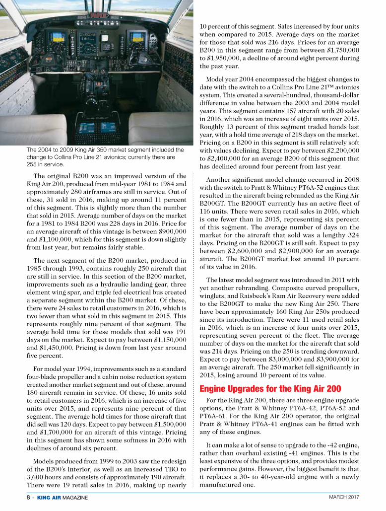
The 2004 to 2009 King Air 350 market segment included the change to Collins Pro Line 21 avionics; currently there are 255 in service.

MARCH 2017 KING AIR MAGAZINE • 9
The -52 or -61 engines are very similar, with the -52 providing a slight cruise speed increase over the -61. In either case, you can expect to realize a 17-knot increase in cruise speed for the -61, and a 26-knot increase for the -52.
Raisbeck Modifications for the King Air 200
Ram Air Recovery is available on the King Air 200 series. This modification improves airflow to the engines, decreasing the engine Interstage Turbine Temperature (ITT) and increasing the available horsepower, delivering significantly improved climb and cruise performance.
Enhanced Performance Leading Edges is another modification available to King Air 200 series owners. This system is a modification to the leading edge of the wing between the fuselage and nacelle. According to Raisbeck, this modification significantly improves climb and cruise performance and reduces stall speeds.
King Air 350 MarketThe King Air 350 debuted in 1990. Although the
model was largely unchanged until upgraded Collins Pro Line 21 avionics were added in 2004, there are still some areas of segmentation, often with different activity levels at either end of the market.
Even though the 350 is largely unchanged from 1990 to 1997, the newer models perform differently in the used market than do the older ones. For this market segment, there are roughly 180 airframes with 14 retail sales in 2016. This equates to about eight percent of the fleet in this segment. Compared to 2015, there were two additional sales for this segment. The average days on the market was 169 days. Pricing on this part of the 350 market was in a decline for 2016; expect to pay between $1,500,000 and $1,900,000 for an average aircraft. This represents about a 10 percent drop from 2015.
For the 1998 to 2003 model years, there are around 195 airframes still in service with 14 retail sales last year – down six units from 2015. This represents seven percent of the fleet, with an average hold time of 187 days. Prices in this market segment have also softened a bit in the latter half of 2016. Expect to pay $1,950,000 to $2,300,000 for an average aircraft; a decline of approximately 10 percent from 2015.
The 2004 to 2009 market segment included the change to Collins Pro Line 21 avionics. There are 255 of these aircraft in service with 14 retail sales in 2016, which is the same as 2015. This represents six percent of its market segment with an average hold time of a lengthy 297 days. Pricing on these 350s
are still relatively soft. Expect to pay $2,400,000 to $3,200,000 for an average aircraft, which is a drop of over 15 percent from 2015.
There have been 340 King Air 350i’s produced with 10 retail sales last year, one fewer than in 2015, representing three percent of the total fleet. Average hold time was a scant 63 days on the market. The 350i market is still trending downward. Prices have fallen over 15 percent from 2015. Expect to pay between $3,500,000 and $4,500,000 for an average aircraft.
As you can see, prices are down for all of these King Airs. The newer models tend to take the biggest hit, as they are still on the steep part of their depreciation curve. After an unprecedented nine years of price declines, there doesn’t appear to be any relief in sight. The good news is that the King Airs have generally held their values better than their jet counterparts. Until we can see a healthier new King Air sales market, we will most likely continue to see annual price declines.
Engine Upgrades – Coming SoonAlthough engine upgrades are not currently available,
Blackhawk’s XP67A engine upgrade is currently in the works. It is expected for the upgrade to have an increased rate of climb, shorter high/hot takeoffs, faster cruise speeds and higher single engine service ceiling. The installation will include two factory new MT five blade composite propellers.
NOTES: Figures for average days on the market and aircraft transaction numbers are courtesy of JETNET L.L.C.
Jim Becker is a graduate of the Aviation Institute at the University of Nebraska at Omaha, and holds an FAA Airframe & Power Plant (A&P) mechanic license. With over 25 years in the aviation industry, 20 of those years have been with Elliott Aviation in the capacity of valuing aircraft. Jim is also an Accredited Senior Appraiser with the American Society of Appraisers. For any specific questions on the value of your aircraft, you can contact him at [email protected] or call (515) 285-6551.
KA
10 • KING AIR MAGAZINE MARCH 2017
I nstrument procedure charts are not the sole domain of Jeppesen (now a Boeing company). Various governmental agencies and private companies have
produced competing charts for decades. Yet, Jeppesen (Jepp) charts have long been the gold standard in Instrument Flight Rules (IFR) procedure publications for turbine aircraft operators the world over. They’ve always presented the detailed textual information and complex graphic depictions inherent to such procedures in well-organized formats that pilots appreciate. While minor tweaks to the basic formats have occurred regularly over the years, major redesigns have been infrequent. However, times are changing and traditional paper charts have now been mostly supplanted by Electronic Flight Bags (EFBs), various tablet apps, and even on-board Multi-Function Displays (MFDs). The full gamut of charting needs can now be neatly stored in such portable and/or installed computer devices. The advantages of quick electronic revisions and pounds of paper removed from the cockpit cannot be overstated. But, charts designed in the era of paper and ring-binders have sometimes suffered from less than ideal formatting when viewed on modern MFDs, EFBs or tablet devices. This is just one of the major issues that Jepp has addressed in their recent redesign of SID/STAR charts; a project that is now several months into a two-year rollout phase.
Coming to a Device Near YouI first became aware of the newly formatted Jepp SID/
STAR charts on a January flight into New York’s JFK only two days after their introduction. That there had been a formatting change was immediately obvious, but the extent of the changes was less noticeable while completing the chores of a complex STAR into one of the world’s busiest airports. Further investigation was definitely in order.
The new format first appeared in the U.S. within the January 13, 2017 revision cycle, but only at five U.S. air ports – Chicago’s O’Hare Int’l (ORD) and Midway Int’l (MDW) and New York City’s “Big Three” of Newark Liberty Int’l (EWR), La Guardia Airport (LGA), and Kennedy Int’l (JFK). Throughout the remainder of 2017 and 2018, the new format will be introduced incrementally across the
company’s worldwide database of nearly 20,000 SID/STAR procedures. Jeppesen has also already applied the new format to several airports outside the U.S., and for familiarization and training purposes. One transition aspect that Jepp is committed to, is ensuring that charts for a given airport will all be upgraded concurrently to avoid having a mix of new and old formats at a single airport. Undoubtedly, with each subsequent revision cycle, your odds of being confronted with a redesigned SID/STAR chart will increase (Figure 1).
Own-Ship Display CapabilitiesOne of the biggest changes Jeppesen has made is the
use of a depicted-to-scale format. This change is not simply a matter of making the plan view map more user-friendly. Of course, the distances between fixes, navaids, courses and terrain/obstructions is far more meaningful when drawn to scale. However, scale drawing also allows modern electronic charting to overlay moving aircraft symbology on the chart. Anyone who has used this
PILOT SPEAKKA
Facelift: Jeppesen SID/STAR Charts Having
“A Little Work Done”by Matthew McDaniel
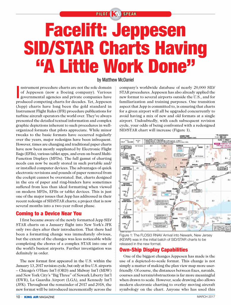
Figure 1: The FLOSI3 RNAV Arrival into Newark, New Jersey (KEWR) was in the initial batch of SID/STAR charts to be released in the new format.
MARCH 2017 KING AIR MAGAZINE • 11
feature on electronic en route maps or approach plates knows the situational awareness advantage it provides. Obviously, the software being used for electronic charts must incorporate own-aircraft capabilities, along with some sort of present-position navigational source input (and appropriate certification, when/where required). With those tools in place, the new scaled format of Jepp’s SID/STAR charts is just the sort of safety enhancement that pilots crave. As with approach plates, there are situations that preclude scale depictions of some portions of the chart. In such cases, the non-scaled portion(s) will be outlined with a dashed-line and labeled “NOT TO SCALE.”
Consolidating Textual DataWhen looking at a paper SID/STAR chart, at
least in most cases, the entirety of the chart is in front of the pilot when referenced. When using electronic means of chart viewing, that is not always the case. Many tablets and EFBs allow easy zooming, panning, and pinching of the chart for easier viewing of one area versus another (a feature that many pilots with aging eyesight appreciate). The problem this can create is that critical textual data, restrictions, and/or limitations are often moved out of view and forgotten. Or, to be referenced, the pilot must pan and swipe while searching for the pertinent information which may be distributed around the edges, corners, or in otherwise uncluttered areas of the chart. To alleviate this problem, Jepp’s new format declutters the plan view by consolidating as much of the textual data as feasible into a single panel at the edge of the chart, most often on the chart’s right side. This allows quicker location of the information initially and eliminates the need to search in multiple locations to gather all the data. While the “briefing strip” that Jepp users are already familiar with remains, even it has been enhanced by always being aligned with the orientation of the procedure itself, which was not always the case in the past (Figure 2).
Jepp’s Top Ten ListJeppesen’s press releases and
online training resources point out that the new format was gener-ated through an Operational Risk Assessment (ORA), pilot research, customer feedback and human fac-tors testing to “improve situation
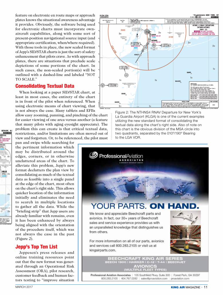
Figure 2: The NTHNS4 RNAV Departure for New York’s La Guardia Airport (KLGA) is one of the current examples utilizing the new standard format of consolidating the textual data along the chart’s right side. Also of note on this chart is the obvious division of the MSA circle into two quadrants, separated by the 010º/190º Bearing to the LGA VOR.
12 • KING AIR MAGAZINE MARCH 2017
awareness, reduce heads down time and increase safety.” They highlight ten main bullet points of the redesign. Other minor changes were incorporated, as well (as noted elsewhere in this article).
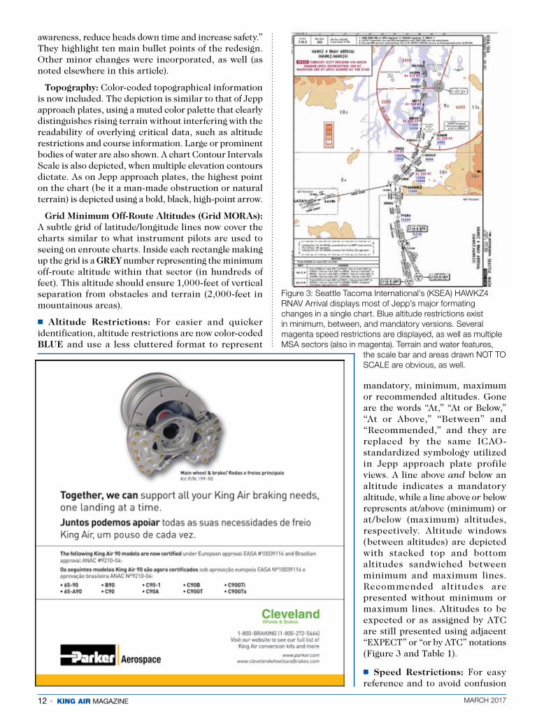
Topography: Color-coded topographical information is now included. The depiction is similar to that of Jepp approach plates, using a muted color palette that clearly distinguishes rising terrain without interfering with the readability of overlying critical data, such as altitude restrictions and course information. Large or prominent bodies of water are also shown. A chart Contour Intervals Scale is also depicted, when multiple elevation contours dictate. As on Jepp approach plates, the highest point on the chart (be it a man-made obstruction or natural terrain) is depicted using a bold, black, high-point arrow.
Grid Minimum Off-Route Altitudes (Grid MORAs): A subtle grid of latitude/longitude lines now cover the charts similar to what instrument pilots are used to seeing on enroute charts. Inside each rectangle making up the grid is a GREY number representing the minimum off-route altitude within that sector (in hundreds of feet). This altitude should ensure 1,000-feet of vertical separation from obstacles and terrain (2,000-feet in mountainous areas).
� Altitude Restrictions: For easier and quicker identification, altitude restrictions are now color-coded BLUE and use a less cluttered format to represent
mandatory, minimum, maximum or recommended altitudes. Gone are the words “At,” “At or Below,” “At or Above,” “Between” and “Recommended,” and they are replaced by the same ICAO-standardized symbology utilized in Jepp approach plate profile views. A line above and below an altitude indicates a mandatory altitude, while a line above or below represents at/above (minimum) or at/below (maximum) altitudes, respectively. Altitude windows (between altitudes) are depicted with stacked top and bottom altitudes sandwiched between minimum and maximum lines. Recommended altitudes are presented without minimum or maximum lines. Altitudes to be expected or as assigned by ATC are still presented using adjacent “EXPECT” or “or by ATC” notations (Figure 3 and Table 1).
� Speed Restrictions: For easy reference and to avoid confusion
Figure 3: Seattle Tacoma International’s (KSEA) HAWKZ4 RNAV Arrival displays most of Jepp’s major formating changes in a single chart. Blue altitude restrictions exist in minimum, between, and mandatory versions. Several magenta speed restrictions are displayed, as well as multiple MSA sectors (also in magenta). Terrain and water features,
the scale bar and areas drawn NOT TO SCALE are obvious, as well.

MARCH 2017 KING AIR MAGAZINE • 13
with altitude restrictions, speed restrictions are now color-coded MAGENTA, both in the procedure’s header (title) information and within the chart’s plan view (Table 2 and Figure 3).
� Minimum Sector Altitude (MSA): The MSA now over-lies the chart’s plan view, rather than being depicted in a separate box, off in one corner. The overlying MSA circle is color-coded MAGENTA, as are the bearings separating sectors of the MSA circle and the altitudes depicted within each sector. The center point defining the MSA circle is identified (both at the point itself and on the MSA circle), as is the MSA diameter when it differs from the standard 25 NM. The minimum altitudes are expressed in whole numbers, but rounded up to the next one-hundred-foot increment (Figure 2).
� Navaids: Navaid symbology has been changed to conform with Jepp enroute charts and ICAO standards. These easily recognizable symbols, along with the removal of associated lat/long information, help in Jeppesen’s efforts to declutter the chart. Since modern GPS and FMS databases are generally programmed via a navaid’s two- or three-letter identifier and already have said navaid’s associated latitude/longitude stored, the
information was certainly contributing to clutter that modern IFR pilots seldom (if ever) use in the terminal environment.
� Holding: Published hold depictions which are based on nautical mile distances or DME leg lengths are now depicted to scale, while holds based on flight time will be noted as “NOT TO SCALE.” Maximum holding speeds are noted at the top of the textual information for the hold. Still included (where appropriate) are the minimum and maximum holding altitudes, MHA and MAX, respectively, below the speed depiction. A “by ATC” notation will appear, as appropriate.
� Secondary IFR Airports: Not included in the previous formats, these airports are now depicted in a subtle GREY color, similar to how they appear on Jepp approach plates. In the U.S., when a single SID or STAR procedure serves multiple airports, the “Also Serves” airports are depicted in BLUE.
� Waypoints: The latitude/longitude coordinates associated with depicted waypoint names have also been removed to declutter the chart’s plan view.
� Scale Bar: It only makes good sense that since these redesigned charts are depicted to scale, that a reference to the specific scale being utilized would be added. Along the left or top edge of the chart, depending upon chart orientation, a scale bar provides inch-to-NM scale information.
Table 1: Examples of the various altitude restriction symbols with the new Jepp SID/STAR format.
Mandatory Altitude Restriction
Between Altitude Restriction
Minimum Altitude or At-or-Above or Above Altitude Restriction
Maximum Altitude or At-or-Below or Below Altitude Restriction
Recommended Altitude
Altitude Restriction with an “or by ATC” notation to indicate this restriction may be amended by ATC.
Altitude Restriction to be expected for planning purposes, though it only becomes mandatory when assigned by ATC.
8000 FL80 ●�
10000 8000
FL100 FL80 ●�
8000 FL80 ●�
10000 FL100 ●�
8000 FL80 ●�
10000 or by ATC
FL100 or by ATC ●�
EXPECT 80000 EXPECT FL80 ●�
Table 2: A side-by-side comparrision of the old and new formatting for both Altitude and Speed Restrictions.
14 • KING AIR MAGAZINE MARCH 2017
Cutting the ClutterAll in all, Jeppesen has done an admirable job of
decluttering their SID/STAR charts. Moving the textual data from random placement within the plan view to a dedicated reading pane has created a far cleaner presentation of the critical route, altitude and speed information. Removal of extraneous latitude/longitude data also really helped to clean up the plan view, especially in complex SID/STARS that have a half-dozen or more fixes and navaids depicted. In their quest to declutter, Jepp even went so far as to shorten its naming conventions for the procedures. Now, rather than spelling out the names in long-form, they are presented in a shorter (but just as easy to read) form, along with the proper flight plan formatting in parenthesis. For example, the HAWKZ FOUR RNAV ARRIVAL would appear as “HAWKZ 4 RNAV ARRIVAL (HAWKZ.HAWKZ4).”
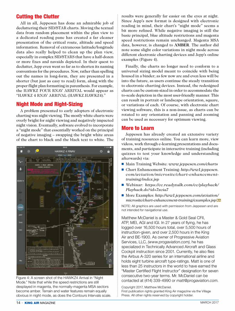
Night Mode and Right-SizingA problem presented to early adopters of electronic
charting was night viewing. The mostly white charts were overly bright for night viewing and negatively impacted night vision. Eventually, software evolved to incorporate a “night mode” that essentially worked on the principal of negative imaging – swapping the bright white areas of the chart to black and the black text to white. The
results were generally far easier on the eyes at night. Since Jepp’s new format is designed with electronic reading in mind, their chart’s “night mode” seems a bit more refined. While negative imaging is still the basic principal, blue altitude restrictions and magenta speed restrictions remain unchanged. Magenta MSA data, however, is changed to AMBER. The author did note some slight color variations in night mode across different electronic charting devices and Jepp’s online examples (Figure 4).
Finally, the charts no longer need to conform to a universal sizing model meant to coincide with being housed in a binder; as few now are and even less will be into the future, as users continue the steady transition to electronic charting devices. Instead, the redesigned charts can be custom-sized in order to accommodate the to-scale depiction in the most user-friendly manner. This can result in portrait or landscape orientation, square, or variations of each. Of course, with electronic chart viewing software, this is a non-issue, as charts can be rotated to any orientation and panning and zooming can be used as necessary for optimum viewing.
More to LearnJeppesen has already created an extensive variety
of training resources online. You can learn more, view videos, work through e-learning presentations and docu-ments, and participate in interactive training (including quizzes to test your knowledge and understanding afterwards) via:� Main Training Website: www.jeppesen.com/charts� Chart Enhancement Training: http://ww1.jeppesen.
com/aviation/microsite/chart-enhancement-training/index.jsp
� Webinar: https://cc.readytalk.com/cc/playback/Playback.do?id=7xcia7
� More Examples: http://ww1.jeppesen.com/aviation/microsite/chart-enhancement-training/examples.jsp
NOTE: All graphics are used with permission from Jeppesen and are not intended for navigational use.
Matthew McDaniel is a Master & Gold Seal CFII, ATP, MEI, AGI and IGI. In 27 years of flying, he has logged over 16,500 hours total, over 5,500 hours of instruction-given, and over 2,500 hours in the King Air and BE-1900. As owner of Progressive Aviation Services, LLC, (www.progaviation.com), he has specialized in Technically Advanced Aircraft and Glass Cockpit instruction since 2001. Currently, he also flies the Airbus A-320 series for an international airline and holds eight turbine aircraft type-ratings. Matt is one of less than 25 instructors in the world to have earned the “Master Certified Flight Instructor” designation for seven consecutive two-year terms. Mr. McDaniel can be contacted at (414) 339-4990 or [email protected].
Copyright 2017, Matthew McDaniel. First publication rights granted King Air magazine via the Village Press. All other rights reserved by copyright holder.
Figure 4: A screen shot of the HAWKZ4 Arrival in “Night Mode.” Note that while the speed restrictions are still desplayed in magenta, the normally-magenta MSA sectors become amber. Terrain and water features remain equally obvious in night mode, as does the Contours Intervals scale.
KA

MARCH 2017 KING AIR MAGAZINE • 15

16 • KING AIR MAGAZINE MARCH 2017
MARCH 2017 KING AIR MAGAZINE • 17
18 • KING AIR MAGAZINE MARCH 2017
The Latest on NextGen and ATC
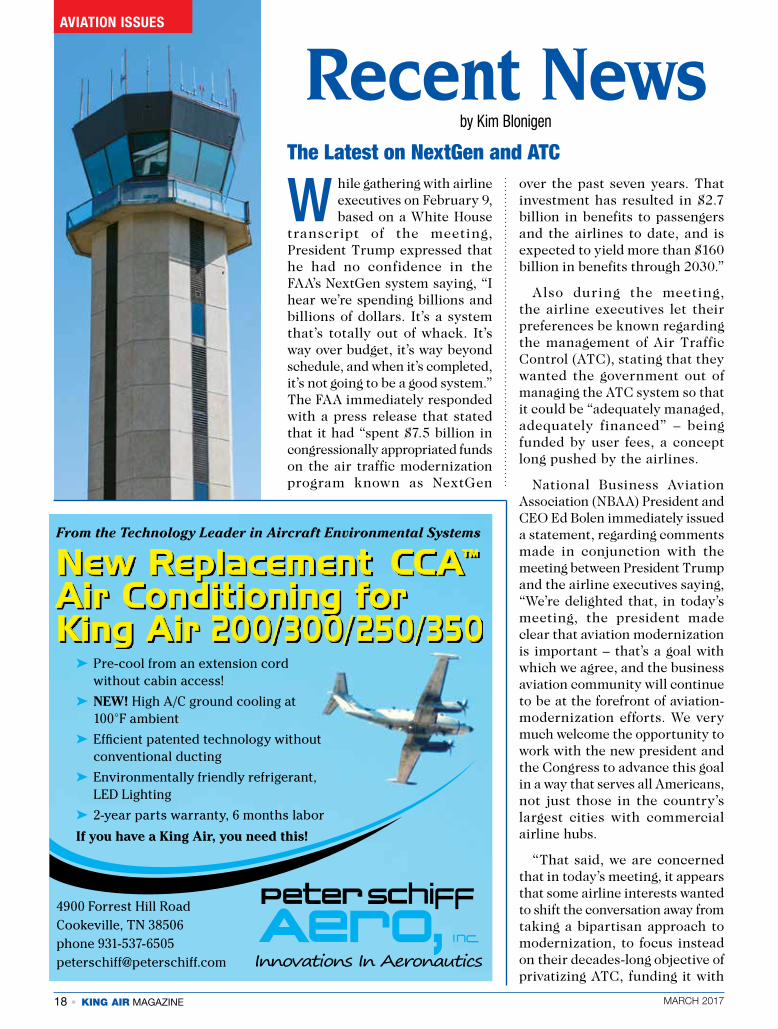
W hile gathering with airline executives on February 9, based on a White House
transcript of the meeting, President Trump expressed that he had no confidence in the FAA’s NextGen system saying, “I hear we’re spending billions and billions of dollars. It’s a system that’s totally out of whack. It’s way over budget, it’s way beyond schedule, and when it’s completed, it’s not going to be a good system.” The FAA immediately responded with a press release that stated that it had “spent $7.5 billion in congressionally appropriated funds on the air traffic modernization program known as NextGen
over the past seven years. That investment has resulted in $2.7 billion in benefits to passengers and the airlines to date, and is expected to yield more than $160 billion in benefits through 2030.”
Also during the meeting, the airline executives let their preferences be known regarding the management of Air Traffic Control (ATC), stating that they wanted the government out of managing the ATC system so that it could be “adequately managed, adequately financed” – being funded by user fees, a concept long pushed by the airlines.
National Business Aviation Association (NBAA) President and CEO Ed Bolen immediately issued a statement, regarding comments made in conjunction with the meeting between President Trump and the airline executives saying, “We’re delighted that, in today’s meeting, the president made clear that aviation modernization is important – that’s a goal with which we agree, and the business aviation community will continue to be at the forefront of aviation-modernization efforts. We very much welcome the opportunity to work with the new president and the Congress to advance this goal in a way that serves all Americans, not just those in the country’s largest cities with commercial airline hubs.
“That said, we are concerned that in today’s meeting, it appears that some airline interests wanted to shift the conversation away from taking a bipartisan approach to modernization, to focus instead on their decades-long objective of privatizing ATC, funding it with
AVIATION ISSUES
Recent Newsby Kim Blonigen
4900 Forrest Hill Road Cookeville, TN 38506 phone 931-537-6505 [email protected]
New Replacement CCA™ Air Conditioning for King Air 200/300/250/350
➤ Pre-cool from an extension cord without cabin access!
➤ NEW! High A/C ground cooling at 100°F ambient
➤ Efficient patented technology without conventional ducting
➤ Environmentally friendly refrigerant, LED Lighting
➤ 2-year parts warranty, 6 months labor
If you have a King Air, you need this!
From the Technology Leader in Aircraft Environmental Systems
MARCH 2017 KING AIR MAGAZINE • 19
new user fees, and placing it under the governing control of a self-interested, airline-centric board of directors,” Bolen continued.
Bolen also noted that there are two sides to the important ATC debate and the president had only heard the airlines’ position, but in fact, surveys of everyday Americans show a majority oppose privatizing the ATC system. “The concerns of these citizens are well-founded – after all, the nation’s aviation system is a public asset, intended to serve the entire public, including the people and businesses in the small towns and rural areas that rely on general aviation,” he said.
The U.S. Department of Defense has also voiced concern over the ATC system becoming privatized, as the military has a “shared infrastructure” with the system and that would definitely need to be addressed.
The FAA recently released Safety Alert for Operators (SAFO) 17001 to alert pilots that operate near the boundaries of Class B airspace to the risk coming into close proximity to other aircraft operating outside of, but near the Class B boundaries. Aircraft operating outside of the Class B airspace may not be under the control of Air Traffic Control (ATC) providing Class B airspace services and therefore may increase the risk of a Near Mid Air Collision (NMAC).
The SAFO emphasizes the importance of a pilot’s role in maintaining proper aircraft separation when operating near Class B airspace boundaries and
caution of inadvertently exiting the airspace, or of the approach path of many instrument arrival and approach procedures may come close to the floor of Class B airspace. Also, during times of high traffic volume, aircraft above the Class B airspace floor may receive ATC instructions that when executed, would cause the airplane to exit the confines of the airspace. Pilots may be unaware of an excursion because they may not be advised of such an event during times of high controller workload.
Pilots are encouraged to thor-oughly review the boundary speci-fications when preparing to operate in or near Class B airspace.
FAA Releases SAFO Regarding Awareness of Class B Airspace Boundaries
KA
20 • KING AIR MAGAZINE MARCH 2017
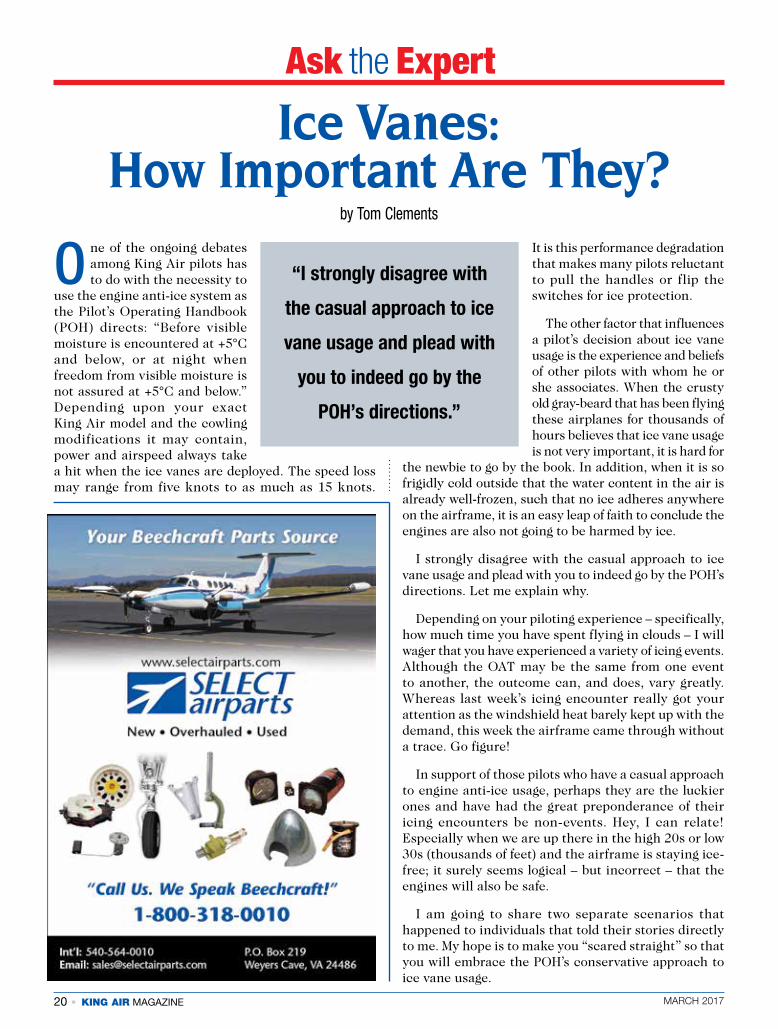
O ne of the ongoing debates among King Air pilots has to do with the necessity to
use the engine anti-ice system as the Pilot’s Operating Handbook (POH) directs: “Before visible moisture is encountered at +5°C and below, or at night when freedom from visible moisture is not assured at +5°C and below.” Depending upon your exact King Air model and the cowling modifications it may contain, power and airspeed always take a hit when the ice vanes are deployed. The speed loss may range from five knots to as much as 15 knots.
It is this performance degradation that makes many pilots reluctant to pull the handles or flip the switches for ice protection.
The other factor that influences a pilot’s decision about ice vane usage is the experience and beliefs of other pilots with whom he or she associates. When the crusty old gray-beard that has been flying these airplanes for thousands of hours believes that ice vane usage is not very important, it is hard for
the newbie to go by the book. In addition, when it is so frigidly cold outside that the water content in the air is already well-frozen, such that no ice adheres anywhere on the airframe, it is an easy leap of faith to conclude the engines are also not going to be harmed by ice.
I strongly disagree with the casual approach to ice vane usage and plead with you to indeed go by the POH’s directions. Let me explain why.
Depending on your piloting experience – specifically, how much time you have spent flying in clouds – I will wager that you have experienced a variety of icing events. Although the OAT may be the same from one event to another, the outcome can, and does, vary greatly. Whereas last week’s icing encounter really got your attention as the windshield heat barely kept up with the demand, this week the airframe came through without a trace. Go figure!
In support of those pilots who have a casual approach to engine anti-ice usage, perhaps they are the luckier ones and have had the great preponderance of their icing encounters be non-events. Hey, I can relate! Especially when we are up there in the high 20s or low 30s (thousands of feet) and the airframe is staying ice-free; it surely seems logical – but incorrect – that the engines will also be safe.
I am going to share two separate scenarios that happened to individuals that told their stories directly to me. My hope is to make you “scared straight” so that you will embrace the POH’s conservative approach to ice vane usage.
Ask the Expert
by Tom Clements
Ice Vanes: How Important Are They?
“I strongly disagree with
the casual approach to ice
vane usage and plead with
you to indeed go by the
POH’s directions.”
MARCH 2017 KING AIR MAGAZINE • 21
The first story involves an old friend of mine with whom I have conducted initial and recurrent King Air training since the 1970s. When I first met this fellow, he was flying a B90 and the various companies he advanced with moved up the King Air ladder so that he was checked out in just about the entire King Air lineup by the time he retired. Although he never argued forcefully with me about ice vane usage, being a kind southern gentleman, I know that he was reluctant to deploy the vanes unless the airframe was collecting significant ice. Nothing I taught could convince him that he was playing a dangerous game.
Then one evening while at home, I got a call from him. It went something like this: “Well, Tommy (He always called me that!), I guess I should have been listening better to you all these years when you preached about ice vane usage. Today, at FL280, we were in visible moisture that was so thin it could have been the contrails of a 747, 20 miles ahead! Of course, I didn’t activate the engine anti-ice. When I started the descent, and changed the power setting, I noticed that things weren’t matching up like they did before. This continued through the landing so I had the mechanics take a look. When they got the flashlights and mirrors to look at the first stage compressor blades, they reported bent blades on both engines. So now we are sending our engines out for repair and will install a
couple of loaners in the meantime. I couldn’t believe it, but I saw it! You were right!”
The second story involved a B200 also flying in the upper 20s, but this time it was night over a dark expanse of the Australian Outback. The pilot noticed that the nav lights were giving a glow on the moisture they were in, so he extended the vanes. He was not sure how long he had unknowingly penetrated the tops of these smooth clouds, but doubted that it could have been for more than a few minutes. When he broke free of the clouds and retracted the vanes, he noticed a 400 ft-lbs, or so, torque split. In the descent, one engine started fluctuating and actually expelling some visible flames at times out of the exhaust stacks. That engine was found to have suffered first stage compressor damage – a bent blade.
For many years now I have always included a copy of a Pratt & Whitney Field Note in the section of my training manuals dealing with ice protection. I am sure those who have trained with me in the past or who have attended the King Air Academy recently have read this before, but I want to print it here for those who have not yet seen it:
In April 1982, a general correspondence was issued concerning the subject of Compressor Ice FOD (Foreign Object Damage). Winter is here again and after three incidents this month,
22 • KING AIR MAGAZINE MARCH 2017
it is time to reprint the original issue with a few new comments.
During this past winter, we have received several engines for first-stage compressor FOD. In each instance, a single blade has been bent with the damage being caused by a soft or dull object – in all probability, ice.
The PT6 nacelle intake system is the result of a very exhaustive and exacting research program. Many hours of development flying in icing conditions with such equipment as closed circuit television cameras in the intake, and fifty million flying hours have proven its effectiveness.
All flight manuals are very explicit when it comes to icing. “Deploy the ice vane prior to penetration.” The interpretation of icing, however, is sometimes a little more difficult. Depending on the OEM (Original Equipment Manufacturer), some will state that +5°C and visible moisture are the criteria. Others will only offer it as a rule-of-thumb. Meanwhile, pilots will, on occasion, wait until first appearance of ice on the windshield.
Night flying imposes an additional measure of difficulty. Here the criteria is sometimes only a check at regular intervals with the wing ice inspection lights. To properly understand when the ice vanes should be deployed, one must understand where the FOD comes from. First, it does not build-up on the intake, break off, and then go through the engine screen. The sheer mass of the ice will stop it from turning the corner and hitting the screen. Secondly, even if it were to get in the intake plenum, the low velocity air at the screen, along with the ¼-inch mesh, would preclude any damage. What actually happens if the vane is not deployed to perform the inertial separation of the moisture, is that this moisture will collect
under the screen and freeze. Either when a piece breaks off, or when penetrating higher OATs and the ice separates due to melting, the engine sustains FOD.
The same will occur with snow. Although below the freezing point, if the deflectors are not deployed and the snow reaches the screen, there is sufficient radiant energy to melt and then refreeze under the screen.
Only if the flight crews understand this principle can they be convinced to properly manage the deicing vanes. One bent blade (which is typical of ice FOD) costs approximately 100 man-hours in shop labor, plus the blade cost and cost of the software kit for reassembly. In addition, when an engine gets disassembled, hot-section components often require premature replacement and some class “A” Service Bulletins require embodiment. This adds unexpected cost to the FOD encounter. I know the pilots will tell you that the ice vane deployment costs them a lot in aircraft performance, but when you consider our economic times, one bent blade can be much more expensive.
Since this was first printed, two areas have come to light as to why flight manual procedures are not being followed.
First is pilot education. Most pilots who have been involved with this FOD are not aware of the mechanism. Give them a copy of this field note. Last year, in the case of one operator, this is all that was necessary to resolve the problem.
The second item is block time, or sector time. The fact is simple: when you deploy the aircraft anti-ice system, the aircraft slows down – some more than others. On short legs this does not amount to much, but when you are flying sectors of greater than one hour, it can be significant.
I cannot overemphasize how important this item of ice FOD is. The issue has gone beyond the dollars and cents phase and is now affecting the reputation of the airframe and the engine.
Does that information – Right from the horse’s mouth, as it were! – give you a better understanding of the mechanism? An important take-away is that what occurs in the engine intake may have little or no similarity to what the airframe is experiencing.

MARCH 2017 KING AIR MAGAZINE • 23
Knowing how fickle ice can be – benign one flight, scary the next – always makes me think of the classic movie line spoken by Clint Eastwood in Dirty Harry: “Are you feeling lucky, punk?”
If you choose to continue to be casual in your deployment of ice vanes, you must be feeling very lucky! I hope your luck holds out. Because if it does not, then the airplane’s owner is going to be faced with a large, wasteful, maintenance expense. Flying a few knots slower will produce a lot less lost time than having the plane be grounded for a month or so for engine repairs!
I will leave you with a positive thought: Do you realize that specific range – the nautical miles you are traveling for each pound of fuel burned, calculated by dividing ground speed by fuel flow – almost always is improved due to ice vane deployment?! Amazing, but true. Unless you are flying at a very high altitude close to the certified ceiling, or fighting an extreme headwind, or you were using a reduced power setting closer to max range than max power, then this statement is true.
You see, since the Fuel Control Unit (FCU) is a governor for compressor speed (N1), the reduction in
intake air density due to ice vane extension makes N1 want to increase due to less compressor air drag. But the FCU reacts by reducing fuel flow to keep N1 constant. The reduction in ground speed is proportionally less than the reduction in fuel flow, so the airplane actually becomes more, not less, fuel efficient. Write down your stabilized ground speed and fuel flow numbers next time, before and after ice vane deployment. Get your smartphone’s calculator and do the division. I’m right, aren’t I? Perhaps that will give you a little comfort when you observe the decrease in speed.
Bottom line? You’ve heard it before but I’ll state it again:
“When in Doubt, Get ‘em Out!”
King Air expert Tom Clements has been flying and instructing in King Airs for over 44 years, and is the author of “The King Air Book.” He is a Gold Seal CFI and has over 23,000 total hours with more than 15,000 in King Airs. For information on ordering his book, go to www.flightreview.net. Tom is actively mentoring the instructors at King Air Academy in Phoenix.
If you have a question you’d like Tom to answer, please send it to Editor Kim Blonigen at [email protected].
KA
by Edward H. Phillips
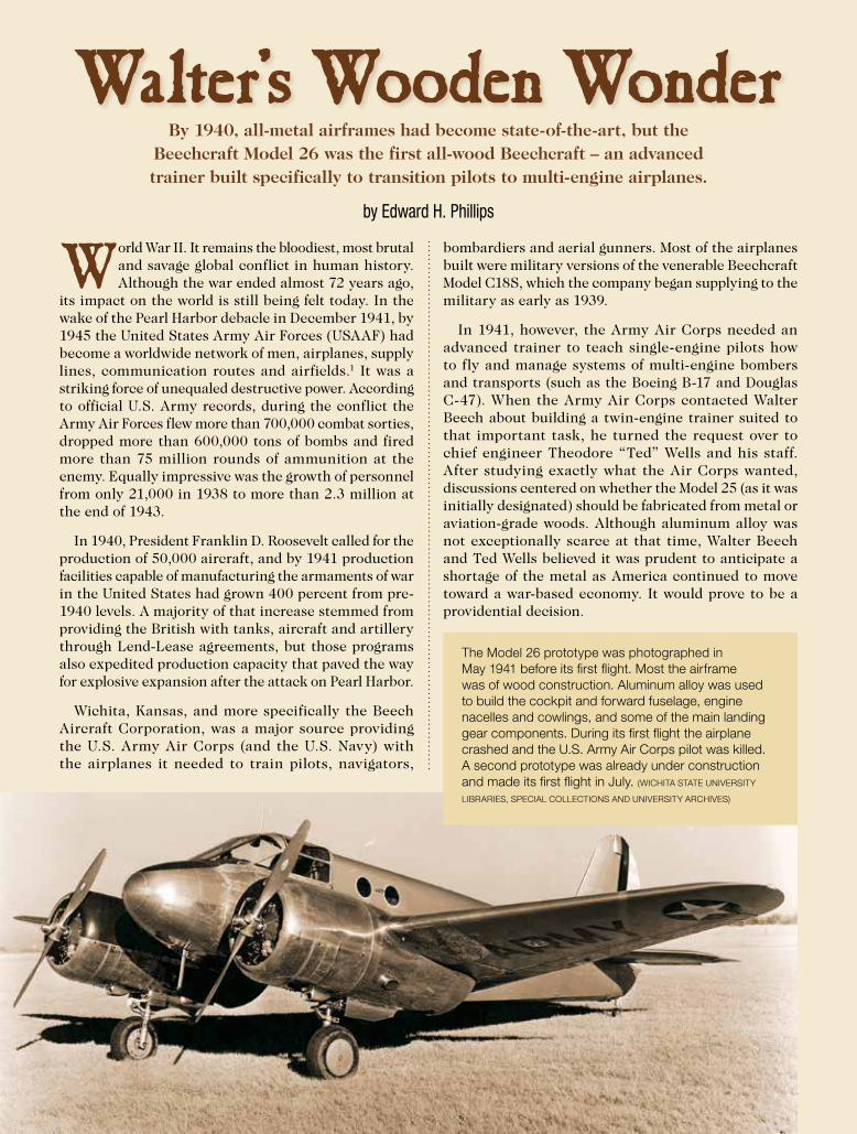
Walter’s Wooden WonderBy 1940, all-metal airframes had become state-of-the-art, but the
Beechcraft Model 26 was the first all-wood Beechcraft – an advanced trainer built specifically to transition pilots to multi-engine airplanes.
World War II. It remains the bloodiest, most brutal and savage global conflict in human history. Although the war ended almost 72 years ago,
its impact on the world is still being felt today. In the wake of the Pearl Harbor debacle in December 1941, by 1945 the United States Army Air Forces (USAAF) had become a worldwide network of men, airplanes, supply lines, communication routes and airfields.1 It was a striking force of unequaled destructive power. According to official U.S. Army records, during the conflict the Army Air Forces flew more than 700,000 combat sorties, dropped more than 600,000 tons of bombs and fired more than 75 million rounds of ammunition at the enemy. Equally impressive was the growth of personnel from only 21,000 in 1938 to more than 2.3 million at the end of 1943.
In 1940, President Franklin D. Roosevelt called for the production of 50,000 aircraft, and by 1941 production facilities capable of manufacturing the armaments of war in the United States had grown 400 percent from pre-1940 levels. A majority of that increase stemmed from providing the British with tanks, aircraft and artillery through Lend-Lease agreements, but those programs also expedited production capacity that paved the way for explosive expansion after the attack on Pearl Harbor.
Wichita, Kansas, and more specifically the Beech Aircraft Corporation, was a major source providing the U.S. Army Air Corps (and the U.S. Navy) with the airplanes it needed to train pilots, navigators,
bombardiers and aerial gunners. Most of the airplanes built were military versions of the venerable Beechcraft Model C18S, which the company began supplying to the military as early as 1939.
In 1941, however, the Army Air Corps needed an advanced trainer to teach single-engine pilots how to fly and manage systems of multi-engine bombers and transports (such as the Boeing B-17 and Douglas C-47). When the Army Air Corps contacted Walter Beech about building a twin-engine trainer suited to that important task, he turned the request over to chief engineer Theodore “Ted” Wells and his staff. After studying exactly what the Air Corps wanted, discussions centered on whether the Model 25 (as it was initially designated) should be fabricated from metal or aviation-grade woods. Although aluminum alloy was not exceptionally scarce at that time, Walter Beech and Ted Wells believed it was prudent to anticipate a shortage of the metal as America continued to move toward a war-based economy. It would prove to be a providential decision.
24 • KING AIR MAGAZINE MARCH 2017
The Model 26 prototype was photographed in May 1941 before its first flight. Most the airframe was of wood construction. Aluminum alloy was used to build the cockpit and forward fuselage, engine nacelles and cowlings, and some of the main landing gear components. During its first flight the airplane crashed and the U.S. Army Air Corps pilot was killed. A second prototype was already under construction and made its first flight in July. (WICHITA STATE UNIVERSITY
LIBRARIES, SPECIAL COLLECTIONS AND UNIVERSITY ARCHIVES)
As a result, the Model 25 would be built using non-strategic materials that were in abundant supply and were relatively easy to obtain. Using wood instead of metal had a number of important advantages, including ease and speed of manufacture, fabrication on a large scale, and the ability to “farm out” responsibility for manufacturing airframe assemblies and components to subcontractors already skilled in woodworking techniques (much as the British de Havilland company did with the famous and versatile, all-wood Mosquito).
Nor was the Beech Aircraft Corporation alone in its quest to build a multi-engine trainer for the Army Air Corps. Across town the Cessna Aircraft Company, which by 1941 was thriving under the able leadership of Dwane L. Wallace and his board of directors, already were building the AT-8 – a military version of the commercial T-50 – and the Curtiss Airplane Division of the Curtiss-Wright Corporation designed the twin-engine Model CW-25, designated AT-9 by the Army Air Corps.
As with the Beechcraft Model 25, the AT-8 and AT-9 also served to familiarize pilots with the handling characteristics of new medium bombers that were beginning to roll off the production lines. These included the Martin B-26 Marauder and the North American B-25 Mitchell. Unlike the Model 25, the AT-8 was of composite construction using a steel tube fuselage, wood wing and
fabric covering, while production versions of the AT-9 were of all-metal construction.
In 1940, the Nazi’s rapid advance across Western Europe stunned France, Belgium and England as the British and their hard-fighting French allies fell back toward Paris and, finally, the beaches of Dunkerque. A heroic stand by the French forces held the Germans at bay just long enough for the evacuation of more than 300,000 Allied soldiers who would survive to fight another day.
Meanwhile, back in Wichita, Ted Wells and his crew were busy finalizing the design details of the Model 25. There was nothing revolutionary or evolutionary about the new Beechcraft’s airframe. The wings were built of wood in three sections, covered in plywood and bonded together using synthetic resin adhesives. Flaps were mounted along the wing trailing edge between the ailerons and the fuselage. One innovative feature of the airplane was its fuel tanks that were made of wood, with a special synthetic rubber lining installed that was not affected by aviation fuels.
The fuselage was fabricated in two main sections with the cockpit, built of aluminum alloy for structural considerations, and the aft section that was an all-wood monocoque design covered with plywood and bonded with synthetic resin adhesives. The horizontal and
MARCH 2017 KING AIR MAGAZINE • 25
26 • KING AIR MAGAZINE MARCH 2017
vertical stabilizers were wood covered with plywood, but the wood control surfaces were covered in doped fabric.
As for ease of fabrication, the wood airframe used no compound curves, and no sophisticated hot-molding processes were required to form many of the component parts. It is estimated that about 85 percent of the Model 25’s major sub-assemblies were built by subcontractors. The two-place cockpit accommodated a cadet pilot and instructor in a side-by-side arrangement, and was equipped with a rail-mounted canopy that slid aft for access. Good visibility from the cockpit was provided by the generous use of window area. Dual controls, an autopilot and full flight instrumentation for “blind flying” were installed.
The Model 25 was powered by two, nine-cylinder, static air-cooled Lycoming R-680-9 radial engines each producing 295 horsepower (sea level) at 2,300 RPM for takeoff, 275 horsepower at 2,200 RPM, and 210 horsepower at 2,000 RPM. The engines were fitted with two-blade, Hamilton-Standard constant-speed propellers with full-feathering capability. The R-680-9 was a more powerful version of the standard engine that equipped thousands of Boeing-Stearman PT-13 primary trainers for the Army Air Corps and N2S-series for the U.S. Navy during the war years.
The conventional landing gear retracted aft and was enclosed by two doors, although a small portion of each
tire was exposed to the airstream. The tailwheel was fixed and non-steerable, and the main landing gear used hydraulic brakes. The use of aluminum alloy was also applied to the engine nacelles and cowlings. Welded steel tubing was used for the engine mounts.
General specifications include:
Length: 27 feet 11 inches Wingspan: 37 feet Wing area: 298 square feet Height: 10 feet 4 inches Empty weight: 4,750 pounds Maximum takeoff weight: 6,130 pounds Range: 750 statute miles Service ceiling: 15,000 feet
According to Beech Aircraft records, development costs for the Model 25 amounted to about $255,000, and in May 1941 a prototype had been completed and prepared for its maiden voyage into the blue skies over Kansas. The pilot assigned to make that flight was Major George Putnam Moody. He joined the Air Corps in 1930, and in 1934 was among the brave but ill-prepared group of Army pilots that briefly replaced commercial airlines flying the air mail. On May 5 Moody took off in the prototype Model 25, but what happened next has been obscured by time and the absence of an official accident report.
At some point during the flight, Moody lost control of the airplane, possibly while evaluating performance with one engine inoperative. It is possible that the airplane stalled and entered a spin from which Moody was unable to recover. He was killed and the Model 25 completely destroyed. A second airplane, designated the Model 26, was completed and made its first flight on July 19, 1941, with Beech Aircraft test pilot H.C. “Ding” Rankin in the left seat and company vice president of sales and marketing, John P. Gaty, acting as co-pilot.
After completion of flight testing by the Army Air Force, the Model 26 was accepted and given the military designation AT-10 and the unofficial nickname, Wichita.2 After the United States entered the war on December 8, 1941, the need for multi-engine trainers greatly increased, and by February 1942 Beechcraft factory workers were busy building and assembling the AT-10. As airplanes rolled off the production lines, Air Corps pilots ferried the ships to bases across the nation. Among the Army bases that received the AT-10 was Valdosta Field, Georgia. The facility opened in September 1941, and on December 6 was renamed Moody Field in honor of Major Moody, who was killed testing the Model 25.
The AT-10 was operated under the Army Air Force Training Command (AAFTC), led by Lt. General Barton K. Yount. The chief focus of the AAFTC was to “get men to the front” as soon as possible – a formidable task given that in early 1942 America was, as it had been in 1917, woefully unprepared for war. That situation
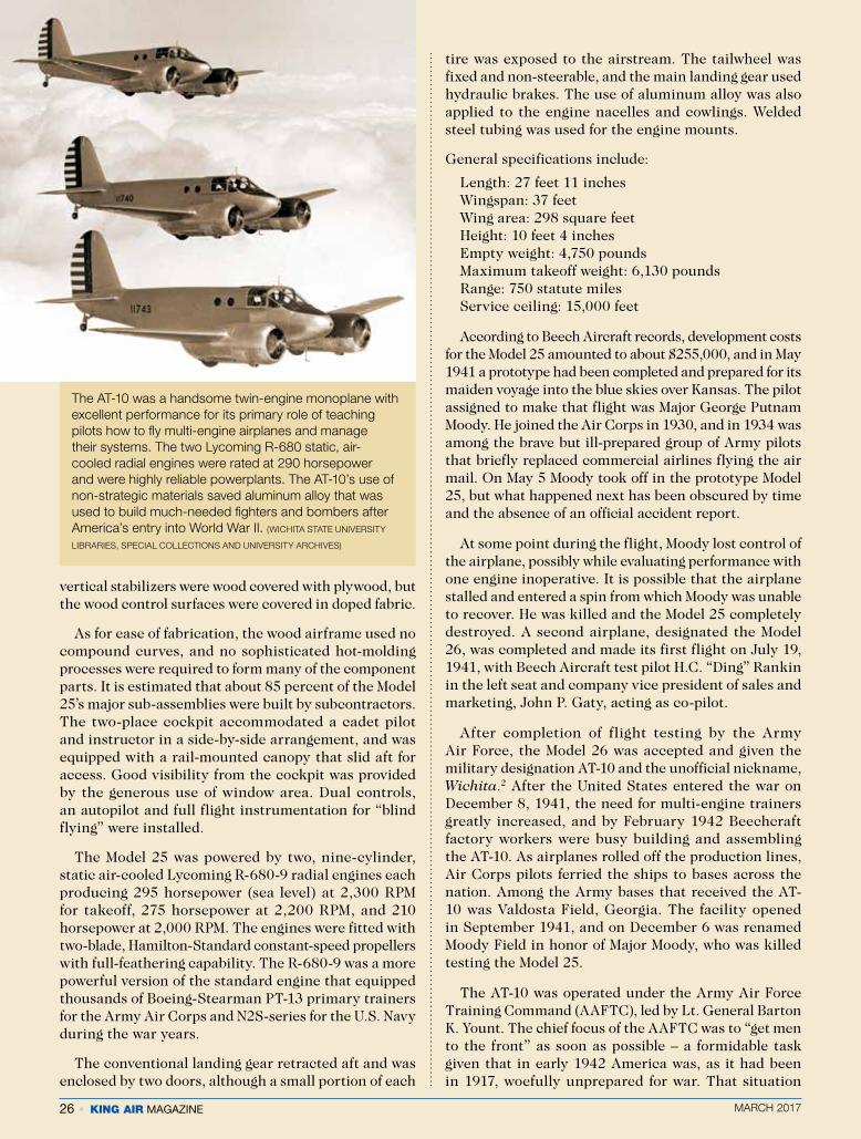
The AT-10 was a handsome twin-engine monoplane with excellent performance for its primary role of teaching pilots how to fly multi-engine airplanes and manage their systems. The two Lycoming R-680 static, air-cooled radial engines were rated at 290 horsepower and were highly reliable powerplants. The AT-10’s use of non-strategic materials saved aluminum alloy that was used to build much-needed fighters and bombers after America’s entry into World War II. (WICHITA STATE UNIVERSITY
LIBRARIES, SPECIAL COLLECTIONS AND UNIVERSITY ARCHIVES)
MARCH 2017 KING AIR MAGAZINE • 27
quickly changed, however, and during the first two years of the conflict about one million men were engaged in training activities as pilots, bombardiers, navigators, radio operators, gunners and technicians. Within the AAFTC was the Flying Training Command, and one of Yount’s first challenges was to build airfields to train aircrews. In the South, where the weather was generally good for flying year-round, training bases sprang up quickly and arriving cadets soon found themselves flying the AT-10 and other training aircraft from half-finished runways, often dodging bulldozers and workmen as they struggled day and night to make the airfields fully operational.
All cadets entered a 10-week advanced flying training course that included 70 hours of flying, 60 hours of ground school and 19 hours of training in military protocol and procedures. Cadets chosen to fly multi-engine bombers and transports flew the AT-9, AT-10, AT-17 and AT-24. Based on their performance, pilots were assigned to type-specific training in medium or heavy bombers, transports, troop carriers or multi-engine fighters that they would fly in combat. Upon completion of their training, graduates received their silver pilot wings and were commissioned as second lieutenants.
Taking Moody Field as an example, beginning in February 1942 and continuing until April 1945, the
Beechcraft AT-10 and other advanced training aircraft were kept busy teaching pilots the art of multi-engine flight, flying by sole reference to flight instruments, and the critical skill of flying in formation. Transitioning from single- to multi-engine airplanes, however, was not a simple task and possessed its own dangers. During the war, there were 191,654 cadets that successfully completed the program, but another 132,993 did not and were “washed out” or killed during training.
Tony Bovinich was among those pilots who trained in the AT-10. “I went to Randolph Field (located in Texas) and flew the AT-10. They were great to fly and I made some real short-field landings over a fence. It did not bother me that the airframe was made of wood. I figured it was put together pretty good or else we would not be flying them.” After his training at Randolph Feld, Bovinich was assigned to Douglas Army Air Base and taught pilots in the Curtiss AT-9, then he was transferred to Roswell, New Mexico, for transition training to the Boeing B-17. By the end of the war he was training to fly the Boeing B-29 Superfortress.3
Another pilot, Homer L. Keisler, graduated from multi-engine transition training at Blythville, Arkansas, where he flew the AT-10, but these airplanes were built by subcontractor Globe Aircraft Corporation, not Beech Aircraft Corporation. Keisler recalled that he and his
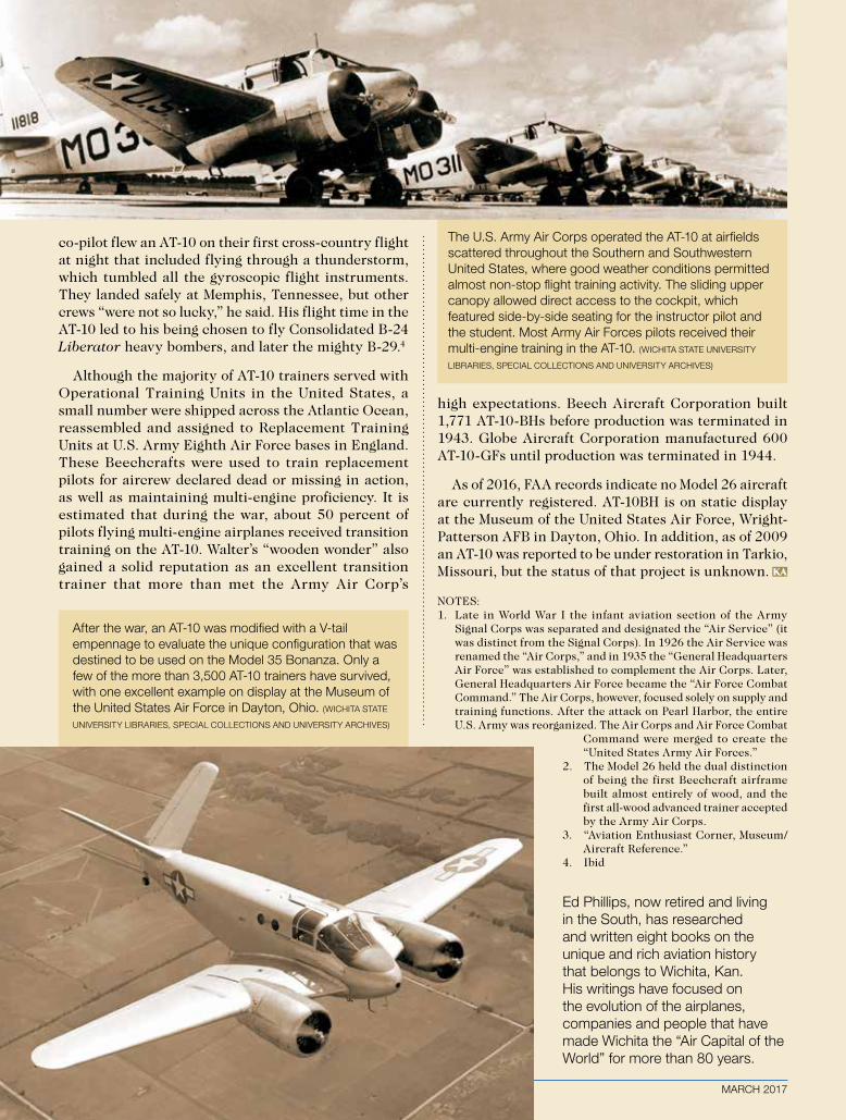
co-pilot flew an AT-10 on their first cross-country flight at night that included flying through a thunderstorm, which tumbled all the gyroscopic flight instruments. They landed safely at Memphis, Tennessee, but other crews “were not so lucky,” he said. His flight time in the AT-10 led to his being chosen to fly Consolidated B-24 Liberator heavy bombers, and later the mighty B-29.4
Although the majority of AT-10 trainers served with Operational Training Units in the United States, a small number were shipped across the Atlantic Ocean, reassembled and assigned to Replacement Training Units at U.S. Army Eighth Air Force bases in England. These Beechcrafts were used to train replacement pilots for aircrew declared dead or missing in action, as well as maintaining multi-engine proficiency. It is estimated that during the war, about 50 percent of pilots flying multi-engine airplanes received transition training on the AT-10. Walter’s “wooden wonder” also gained a solid reputation as an excellent transition trainer that more than met the Army Air Corp’s
high expectations. Beech Aircraft Corporation built 1,771 AT-10-BHs before production was terminated in 1943. Globe Aircraft Corporation manufactured 600 AT-10-GFs until production was terminated in 1944.
As of 2016, FAA records indicate no Model 26 aircraft are currently registered. AT-10BH is on static display at the Museum of the United States Air Force, Wright-Patterson AFB in Dayton, Ohio. In addition, as of 2009 an AT-10 was reported to be under restoration in Tarkio, Missouri, but the status of that project is unknown.
NOTES:1. Late in World War I the infant aviation section of the Army
Signal Corps was separated and designated the “Air Service” (it was distinct from the Signal Corps). In 1926 the Air Service was renamed the “Air Corps,” and in 1935 the “General Headquarters Air Force” was established to complement the Air Corps. Later, General Headquarters Air Force became the “Air Force Combat Command.” The Air Corps, however, focused solely on supply and training functions. After the attack on Pearl Harbor, the entire U.S. Army was reorganized. The Air Corps and Air Force Combat
Command were merged to create the “United States Army Air Forces.”
2. The Model 26 held the dual distinction of being the first Beechcraft airframe built almost entirely of wood, and the first all-wood advanced trainer accepted by the Army Air Corps.
3. “Aviation Enthusiast Corner, Museum/Aircraft Reference.”
4. Ibid
Ed Phillips, now retired and living in the South, has researched and written eight books on the unique and rich aviation history that belongs to Wichita, Kan. His writings have focused on the evolution of the airplanes, companies and people that have made Wichita the “Air Capital of the World” for more than 80 years.
MARCH 2017
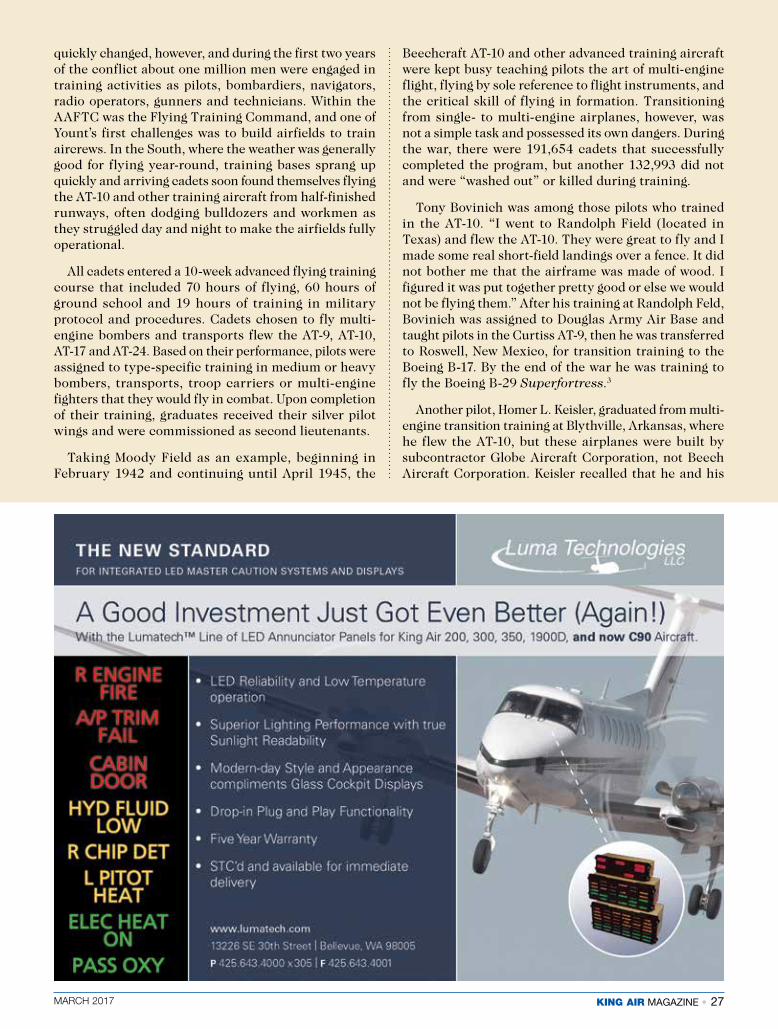
The U.S. Army Air Corps operated the AT-10 at airfields scattered throughout the Southern and Southwestern United States, where good weather conditions permitted almost non-stop flight training activity. The sliding upper canopy allowed direct access to the cockpit, which featured side-by-side seating for the instructor pilot and the student. Most Army Air Forces pilots received their multi-engine training in the AT-10. (WICHITA STATE UNIVERSITY
LIBRARIES, SPECIAL COLLECTIONS AND UNIVERSITY ARCHIVES)
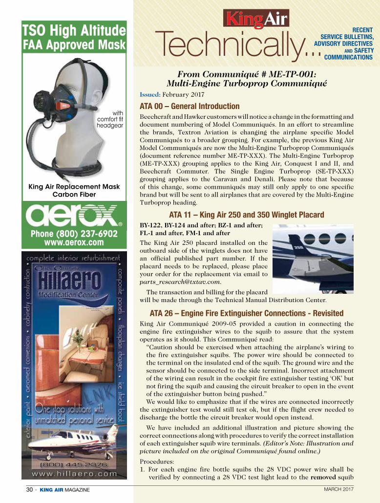
After the war, an AT-10 was modified with a V-tail empennage to evaluate the unique configuration that was destined to be used on the Model 35 Bonanza. Only a few of the more than 3,500 AT-10 trainers have survived, with one excellent example on display at the Museum of the United States Air Force in Dayton, Ohio. (WICHITA STATE
UNIVERSITY LIBRARIES, SPECIAL COLLECTIONS AND UNIVERSITY ARCHIVES)
KA

MARCH 2017 KING AIR MAGAZINE • 29
Textron Aviation Enhances 1Call Support for European Customers
Textron Aviation announced it has strengthened its 1Call support to further meet the unique needs of its European customers. Now with increased capabilities during peak hours in Europe, the 1Call team has enhanced its multi-lingual support for customers who speak English, German, French and Spanish.
Beechcraft King Air, Hawker and Cessna Citation customers around the world needing immediate support can contact the 1Call team 24/7 by dialing +1 (316) 517-2090. 1Call provides a single point of contact during unscheduled maintenance events and offers prioritized technical support, expedited parts ordering, alternative lift solutions or mobile service unit scheduling. Each AOG and unscheduled maintenance event is managed by AOG specialists through successful resolution.
Textron Aviation serves its European customers with six company-owned service centers, five line maintenance stations, a parts distribution center located in Düsseldorf, Germany, which houses more than 225,000 parts, and a team of more than 400 employees, comprised of engineers, service technicians, field service representatives and sales representatives.
Epic Fuels and Signature Issue New Payment Card
Epic Fuels and Signature Flight Support have launched the Signature Flight Support Multi Service Aviation co-branded aviation card. It will be accepted at 8,000 locations worldwide, including all Signature locations in the U.S. and Canada, as well as at all Epic and UVair FBO Network branded facilities.
New cards will be sent to existing customers beginning in the first quarter, and applications for new cards can be submitted at any Signature FBO. Cards can be tailored to aviation department requirements, such as assigned to tail numbers or pilots and require no fuel releases in the U.S.
Pro Star Receives FAA Approval on Amended STCPro Star Aviation LLC has ob-
tained Federal Aviation Admin-istration (FAA) approval for an amendment to Supplemental Type Certificate (STC) – Installation of Universal Antenna Mount (UAM) and Lower Fuselage Radome, an STC applicable to the Beechcraft King Air B300, Super King Air 350, B300C and Super King Air 350C models. The amendment, a result of feedback from industry users,
makes the design of the STC more versatile and mission flexible, while improving overall system inspection methods and operations.
Details of the STC Amendment:
� Operational configurations were expanded to allow up to four antennas to be installed on the UAM when no radome is installed.
� An optional design for aircraft pressure feedthru panels was added, allowing the panels to be removed from the interior of the aircraft when the radome and UAM are installed. This optional design facilitates the required visual inspections of the UAM and radome, allowing them to be accomplished without having to remove the radome and/or its sensitive payload.
� UAM visual inspection intervals were increased to be accomplished at 800 hours/Phase 4 inspection in the applicable Instructions for Continued Airworthiness (ICA), aligning them with similar inspections.
� Deviations found in follow-on installations in radome mounting points due to variations in aircraft production were incorporated.
Pro Star Aviation, with the support of its in-house Organizational Designation Authorization (ODA) delegation, routinely performs engineering and design work for specialized mission equipment, such as the UAM and Lower Fuselage Radome. The company specializes in business and corporate aircraft installations, maintenance and modifications; avionics service and installations; major alterations and repairs; STC development and certification service; AOG support and service; and Part 135 and 91 aircraft management. Its main facility is located at the Manchester-Boston Regional Airport (MHT) in Londonderry, New Hampshire.
For additional information, please contact Pro Star Aviation’s Sales Department at (603) 627-7827.
VALUE ADDEDK A
BUY OR RENT
PRODUCTS INC.
Emergency LiferaftCall Survival Products, the manufacturer, for cutomer/distributor/service info Phone: (954) 966-7329 FAX: (954) 966-3584 5614 SW 25 St., Hollywood, FL 33023 www.survivalproductsinc.com [email protected]
the World’s…• smallest package • lightest weight • least expensiveNew!!! FAA TSO Approved Life Rafts Made in USA
4-6 MAN 9-13 MAN 4"x12"x14" 5"x12"x14" 12 lbs. 18 lbs. $1,510 $1,960 TSO’d& NONTSO’d
30 • KING AIR MAGAZINE MARCH 2017
From Communiqué # ME-TP-001: Multi-Engine Turboprop Communiqué
Issued: February 2017
ATA 00 – General Introduction Beechcraft and Hawker customers will notice a change in the formatting and document numbering of Model Communiqués. In an effort to streamline the brands, Textron Aviation is changing the airplane specific Model Communiqués to a broader grouping. For example, the previous King Air Model Communiqués are now the Multi-Engine Turboprop Communiqués (document reference number ME-TP-XXX). The Multi-Engine Turboprop (ME-TP-XXX) grouping applies to the King Air, Conquest I and II, and Beechcraft Commuter. The Single Engine Turboprop (SE-TP-XXX) grouping applies to the Caravan and Denali. Please note that because of this change, some communiqués may still only apply to one specific brand but will be sent to all airplanes that are covered by the Multi-Engine Turboprop heading.
ATA 11 – King Air 250 and 350 Winglet PlacardBY-122, BY-124 and after; BZ-1 and after; FL-1 and after, FM-1 and after
The King Air 250 placard installed on the outboard side of the winglets does not have an official published part number. If the placard needs to be replaced, please place your order for the replacement via email to [email protected].
The transaction and billing for the placard will be made through the Technical Manual Distribution Center.
ATA 26 – Engine Fire Extinguisher Connections - Revisited King Air Communiqué 2009-05 provided a caution in connecting the engine fire extinguisher wires to the squib to assure that the system operates as it should. This Communiqué read:
“Caution should be exercised when attaching the airplane’s wiring to the fire extinguisher squibs. The power wire should be connected to the terminal on the insulated end of the squib. The ground wire and the sensor should be connected to the side terminal. Incorrect attachment of the wiring can result in the cockpit fire extinguisher testing ‘OK’ but not firing the squib and causing the circuit breaker to open in the event of the extinguisher button being pushed.” We would like to emphasize that if the wires are connected incorrectly
the extinguisher test would still test ok, but if the flight crew needed to discharge the bottle the circuit breaker would open instead.
We have included an additional illustration and picture showing the correct connections along with procedures to verify the correct installation of each extinguisher squib wire terminals. (Editor’s Note: Illustration and picture included on the original Communiqué found online.)
Procedures:1. For each engine fire bottle squibs the 28 VDC power wire shall be
verified by connecting a 28 VDC test light lead to the removed squib
Technically...RECENT
SERVICE BULLETINS,ADVISORY DIRECTIVES
AND SAFETY COMMUNICATIONS
King Air Replacement Mask Carbon Fiber
Phone (800) 237-6902 www.aerox.com
TSO High Altitude FAA Approved Mask
with comfort fit headgear
MARCH 2017 KING AIR MAGAZINE • 31
power wire terminal and the other test light lead to a good fuselage grounded part or screw in the wheel well. Next, press the fire wall valve switch to close the fire wall valve and arm the fire extinguisher. The Fire EXTINGUISHER PUSH light and the test light should both light with low intensity. Next, press and hold the left fire extinguisher switch. The Fire EXTINGUISHER PUSH light should extinguish and the test light should increase in intensity.(Test light consists of one 327 light bulb connected to two 22 gauge wires with alligator clips.)
2. The ground wires shall be tested by connecting one lead of an ohmmeter to the removed squib ground terminal wire on each squib and the other lead to a good fuselage grounded part / screw in the wheel well. The resistance value of the ground wire should be close to zero ohms.
If either of the above do not test correctly, further troubleshooting and repair is required.
Note: We will submit a Publications Change Request to add this procedure to the appropriate manuals.
ATA 30 – King Air 250 Propeller De-ice Boot Protection Circuit Kit
BB-1509 and after; BL-141 and after; BY-1 and after; BZ-1 and after with Composite Propeller Blade STC SA02130SE
King Air Communiqué 2015-07 described a condition in which severe damage to the propeller de-ice boots can occur if the Prop De-Ice system was left ON with the engines not running. Textron Aviation has developed a kit in which power is prevented from reaching the de-ice boots if the Prop De-Ice system is left in the ON position.
The part number of the kit is 101-3301-0001 and it is applicable to serial number airplanes mentioned above.
The kit consists of replacing the engine oil pressure switch with one that will send a signal to a PCB indicating that oil pressure is present before power is allowed to flow to the de-ice boots.
ATA 52 - Emergency Exit Door Handle Spring Due to issues on some King Air 300/B300 and 200/B200 series aircraft where the emergency exit exterior door handle was reported as not fitting flush with the door, Textron Aviation has approved use of a spring that provides more tension for holding the handle flush. The original 100942H0016-16 spring can be replaced with a 100942H0016-12 that has less active coils and provides more tension for the door handle to stay flush. This spares option will be added to the applicable Illustrated Parts Catalog in future revisions.
The above information is abbreviated for space purposes. For the entire communication,
go to www.txtavsupport.com.
What Is the Difference Between the G & D Aero Tinted Window Insert
and the Polaroid Interior Window Insert?
The $$$$$ Cost
STC’D-PMA /FAA APPROVED
KING AIRWINDOW INSERTS
G & D AERO PRODUCTS
951-443-1224
With the G & D Aero tinted window you have full time protection against the sun and the ability to keep your passengers cool and comfortable. No need to make any adjustments to the windows because the inserts work full time.

32 • KING AIR MAGAZINE MARCH 2017
A DV E R T I S I N G I N D E X
ADVERTISING DIRECTOR JOHN SHOEMAKER2779 Aero Park Drive, Traverse City, MI 49686
Phone: 1-800-773-7798 Fax: (231) 946-9588 • E-mail: [email protected]
Apex Aviation Inc. ........................................31Airtext ......................................................... 13AVCON Industries Inc. .................................. 4B/E Aerospace, Inc. ..................................... 7Blackhawk Modification ........Inside Front CoverCleveland Wheels & Brakes ......................... 12Elliott Aviation .................................Back CoverG & D Aero Products Inc ..............................31Hillaero Modification Center .........................30JP Instruments ............................................ 15King Air Academy ........................................25Lighthawk ...................................................32Luma Technologies LLC ...............................27More Company ............................................ 4Murmer Aircraft Services .............................22National Flight Simulator .............................. 9NBAA .......................................................... 19Paul Bowen .................................................32Peter Schiff Aero Inc. ................................... 18Pilots N Paws ..............................................32Precision Aviation Group ..............................21Professional Aviation Associates ................... 11Raisbeck Engineering............................. 16, 17Select Airparts ............................................20Shaw Aerox LLC ..........................................30Survival Products Inc ...................................29Trace Aviation ..............................................32Tru-Simulation + Training............................. 5West Coast Aircraft Sales ..... Inside Back CoverWinner Aviation Inc. .....................................23
Pilots N Paws® is an online meeting place for pilots and other volunteerswho help to transport rescue animals by air. The mission of the site is to provide a user-friendly communication venue between those that rescue, shelter, and foster animals; and pilots and plane owners willing to assist with the transportation of these animals.
Joining is easy and takes just a minute of your time.
www.pilotsnpaws.org
He’s not a pilot but when you need to talk about aviation marketing, John Shoemaker speaks your language. And more importantly, he listens.
Call him today and find how the publications he serves, and the markets they reach, can help your aviation related business grow.
800-773-7798VP Demand Creation Services –
serving your advertising needs with
these fine aviation publications:
● ABS ● Cirrus Pilot ● Comanche Flyer
● King Air ● MMOPA ● Twin & Turbine
“Rogerthat!”
Your Source for King Air Landing Gear
• Inspect • Overhaul • Exchange • Install • Complete Ship Sets • King Air Aircraft Maintenance
601-936-3599 • www.traceaviation.com

MARCH 2017 KING AIR MAGAZINE • 3

4 • KING AIR MAGAZINE MARCH 2017


![KingAir C90 Flight Manual[1]](https://img.pdfslide.us/doc/110x75/54084ff7dab5cac8598b48bd/kingair-c90-flight-manual1.jpg)