Embed Size (px)
Citation preview

Kinetix� Electrostatic Spray GunManual Airless
Customer Product ManualPart 334598G03
Issued 8/08
NORDSON CORPORATION AMHERST, OHIO USA
For parts and technical support, call the Finishing Customer Support Center at (800) 433-9319.
Check http://emanuals.nordson.com/finishing for the latest version.This document is subject to change without notice.
CAPPROVED
USFM
Part 334598G03 � 2008 Nordson Corporation
Contact UsNordson Corporation welcomes requests for information, comments, andinquiries about its products. General information about Nordson can befound on the Internet using the following address:http://www.nordson.com.Address all correspondence to:
Nordson CorporationAttn: Customer Service555 Jackson StreetAmherst, OH 44001
NoticeThis is a Nordson Corporation publication which is protected by copyright.Original copyright date 2000. No part of this document may bephotocopied, reproduced, or translated to another language without theprior written consent of Nordson Corporation. The information containedin this publication is subject to change without notice.
Trademarks
Cross-Cut, Kinetix, Nordson, and the Nordson logo are registeredtrademarks of Nordson Corporation.
Loctite is a registered trademark of Henkel Loctite Corporation.
MagnaLube is a registered trademark of General Magnaplate Corporation.
Perlast is a registered trademark of Precision Polymer EngineeringLimited.
Viton is a registered trademark of E. I. DuPont de Nemours and Company.

Table of Contents i
Part 334598G03� 2008 Nordson Corporation
Table of Contents
Safety 1-1. . . . . . . . . . . . . . . . . . . . . . . . . . . . . . . . . . . . . . . . . . . . . . . . . .Introduction 1-1. . . . . . . . . . . . . . . . . . . . . . . . . . . . . . . . . . . . . . . . . . . . .Qualified Personnel 1-1. . . . . . . . . . . . . . . . . . . . . . . . . . . . . . . . . . . . . .Intended Use 1-1. . . . . . . . . . . . . . . . . . . . . . . . . . . . . . . . . . . . . . . . . . . .Regulations and Approvals 1-2. . . . . . . . . . . . . . . . . . . . . . . . . . . . . . . .Personal Safety 1-2. . . . . . . . . . . . . . . . . . . . . . . . . . . . . . . . . . . . . . . . .
High-Pressure Fluids 1-3. . . . . . . . . . . . . . . . . . . . . . . . . . . . . . . . . . .Fire Safety 1-4. . . . . . . . . . . . . . . . . . . . . . . . . . . . . . . . . . . . . . . . . . . . . .
Halogenated Hydrocarbon Solvent Hazards 1-4. . . . . . . . . . . . . . .Action in the Event of a Malfunction 1-5. . . . . . . . . . . . . . . . . . . . . . . .Disposal 1-5. . . . . . . . . . . . . . . . . . . . . . . . . . . . . . . . . . . . . . . . . . . . . . . .Safety Label 1-5. . . . . . . . . . . . . . . . . . . . . . . . . . . . . . . . . . . . . . . . . . . .
Description 2-1. . . . . . . . . . . . . . . . . . . . . . . . . . . . . . . . . . . . . . . . . . . . .Introduction 2-1. . . . . . . . . . . . . . . . . . . . . . . . . . . . . . . . . . . . . . . . . . . . .Airless Description 2-2. . . . . . . . . . . . . . . . . . . . . . . . . . . . . . . . . . . . . . .Features 2-2. . . . . . . . . . . . . . . . . . . . . . . . . . . . . . . . . . . . . . . . . . . . . . . .Options 2-2. . . . . . . . . . . . . . . . . . . . . . . . . . . . . . . . . . . . . . . . . . . . . . . . .Coating Materials 2-2. . . . . . . . . . . . . . . . . . . . . . . . . . . . . . . . . . . . . . . .Theory of Operation 2-3. . . . . . . . . . . . . . . . . . . . . . . . . . . . . . . . . . . . .
Electrostatic Charge 2-3. . . . . . . . . . . . . . . . . . . . . . . . . . . . . . . . . . .Fluid Flow 2-3. . . . . . . . . . . . . . . . . . . . . . . . . . . . . . . . . . . . . . . . . . . .Air Flow 2-3. . . . . . . . . . . . . . . . . . . . . . . . . . . . . . . . . . . . . . . . . . . . . .
Installation 3-1. . . . . . . . . . . . . . . . . . . . . . . . . . . . . . . . . . . . . . . . . . . . .Preparation 3-1. . . . . . . . . . . . . . . . . . . . . . . . . . . . . . . . . . . . . . . . . . . . .Typical Airless System 3-2. . . . . . . . . . . . . . . . . . . . . . . . . . . . . . . . . . . .Air and Fluid Hose Connections 3-3. . . . . . . . . . . . . . . . . . . . . . . . . . . .
Air Hose 3-3. . . . . . . . . . . . . . . . . . . . . . . . . . . . . . . . . . . . . . . . . . . . . .Fluid Hose 3-3. . . . . . . . . . . . . . . . . . . . . . . . . . . . . . . . . . . . . . . . . . .
Connecting the Fluid Hose 3-5. . . . . . . . . . . . . . . . . . . . . . . . . . .Gun Cable 3-5. . . . . . . . . . . . . . . . . . . . . . . . . . . . . . . . . . . . . . . . . . . . . .Securing the Hoses and Cables 3-6. . . . . . . . . . . . . . . . . . . . . . . . . . . .
Gun Cable 3-6. . . . . . . . . . . . . . . . . . . . . . . . . . . . . . . . . . . . . . . . . . . .Air and Fluid Hoses 3-6. . . . . . . . . . . . . . . . . . . . . . . . . . . . . . . . . . . .
Installing the Nozzle and Gasket with Restrictor 3-6. . . . . . . . . . . . .
Operation 4-1. . . . . . . . . . . . . . . . . . . . . . . . . . . . . . . . . . . . . . . . . . . . . .Introduction 4-1. . . . . . . . . . . . . . . . . . . . . . . . . . . . . . . . . . . . . . . . . . . . .Daily Startup 4-2. . . . . . . . . . . . . . . . . . . . . . . . . . . . . . . . . . . . . . . . . . . .Spray Pattern and Atomization Adjustments 4-3. . . . . . . . . . . . . . . . .Shutdown 4-4. . . . . . . . . . . . . . . . . . . . . . . . . . . . . . . . . . . . . . . . . . . . . . .
Short-Term 4-4. . . . . . . . . . . . . . . . . . . . . . . . . . . . . . . . . . . . . . . . . . .Long-Term 4-4. . . . . . . . . . . . . . . . . . . . . . . . . . . . . . . . . . . . . . . . . . . .Multi-Component Coatings 4-4. . . . . . . . . . . . . . . . . . . . . . . . . . . . . .

Table of Contentsii
Part 334598G03 � 2008 Nordson Corporation
Maintenance 5-1. . . . . . . . . . . . . . . . . . . . . . . . . . . . . . . . . . . . . . . . . . .Introduction 5-1. . . . . . . . . . . . . . . . . . . . . . . . . . . . . . . . . . . . . . . . . . . . .Daily 5-1. . . . . . . . . . . . . . . . . . . . . . . . . . . . . . . . . . . . . . . . . . . . . . . . . . .Periodically 5-3. . . . . . . . . . . . . . . . . . . . . . . . . . . . . . . . . . . . . . . . . . . . .
System Flushing 5-3. . . . . . . . . . . . . . . . . . . . . . . . . . . . . . . . . . . . . .Spray Gun Cleaning 5-4. . . . . . . . . . . . . . . . . . . . . . . . . . . . . . . . . . .
Routine Cleaning 5-4. . . . . . . . . . . . . . . . . . . . . . . . . . . . . . . . . . . .Extensive Cleaning 5-5. . . . . . . . . . . . . . . . . . . . . . . . . . . . . . . . . .
Electrostatic System Checks 5-5. . . . . . . . . . . . . . . . . . . . . . . . . . . . . .
Troubleshooting 6-1. . . . . . . . . . . . . . . . . . . . . . . . . . . . . . . . . . . . . . . .Introduction 6-1. . . . . . . . . . . . . . . . . . . . . . . . . . . . . . . . . . . . . . . . . . . . .Common Problems 6-2. . . . . . . . . . . . . . . . . . . . . . . . . . . . . . . . . . . . . . .Spray Pattern/Film Build Troubleshooting 6-3. . . . . . . . . . . . . . . . . . .Electrostatic Troubleshooting 6-4. . . . . . . . . . . . . . . . . . . . . . . . . . . . . .Multiplier Continuity and Resistance Check 6-5. . . . . . . . . . . . . . . . . .Gun Cable Continuity Check 6-6. . . . . . . . . . . . . . . . . . . . . . . . . . . . . .
Repair 7-1. . . . . . . . . . . . . . . . . . . . . . . . . . . . . . . . . . . . . . . . . . . . . . . . .Tools/Supplies Required 7-2. . . . . . . . . . . . . . . . . . . . . . . . . . . . . . . . . .Nozzle, Restrictor, and Fluid Tip Replacement 7-2. . . . . . . . . . . . . . .Trigger Lock Replacement 7-4. . . . . . . . . . . . . . . . . . . . . . . . . . . . . . . .Air Inlet Fitting Replacement 7-4. . . . . . . . . . . . . . . . . . . . . . . . . . . . . .Ball Tip and Packing Cartridge Replacement 7-6. . . . . . . . . . . . . . . .
Preparation 7-6. . . . . . . . . . . . . . . . . . . . . . . . . . . . . . . . . . . . . . . . . . .Spray Gun Disassembly 7-6. . . . . . . . . . . . . . . . . . . . . . . . . . . . . . . .Ball Tip and Packing Cartridge Removal 7-7. . . . . . . . . . . . . . . . .Ball Tip and Packing Cartridge Installation 7-9. . . . . . . . . . . . . . . .Spray Gun Assembly 7-9. . . . . . . . . . . . . . . . . . . . . . . . . . . . . . . . . .
Air Valve Replacement 7-10. . . . . . . . . . . . . . . . . . . . . . . . . . . . . . . . . . .Back Cover Removal 7-10. . . . . . . . . . . . . . . . . . . . . . . . . . . . . . . . . .Air Valve Removal 7-10. . . . . . . . . . . . . . . . . . . . . . . . . . . . . . . . . . . . .Air Valve Installation 7-12. . . . . . . . . . . . . . . . . . . . . . . . . . . . . . . . . . .
Multiplier Replacement 7-12. . . . . . . . . . . . . . . . . . . . . . . . . . . . . . . . . . .Multiplier Removal 7-12. . . . . . . . . . . . . . . . . . . . . . . . . . . . . . . . . . . . .Multiplier Installation 7-14. . . . . . . . . . . . . . . . . . . . . . . . . . . . . . . . . . .
Gun Cable Replacement 7-14. . . . . . . . . . . . . . . . . . . . . . . . . . . . . . . . .Cable Removal 7-14. . . . . . . . . . . . . . . . . . . . . . . . . . . . . . . . . . . . . . . .Cable Installation 7-16. . . . . . . . . . . . . . . . . . . . . . . . . . . . . . . . . . . . . .
Fluid Supply Hose Replacement 7-16. . . . . . . . . . . . . . . . . . . . . . . . . . .Fluid Hose Removal 7-16. . . . . . . . . . . . . . . . . . . . . . . . . . . . . . . . . . .Install the Fluid Hose 7-17. . . . . . . . . . . . . . . . . . . . . . . . . . . . . . . . . . .
Service Illustration and Notes 7-18. . . . . . . . . . . . . . . . . . . . . . . . . . . . .

Table of Contents iii
Part 334598G03� 2008 Nordson Corporation
Parts 8-1. . . . . . . . . . . . . . . . . . . . . . . . . . . . . . . . . . . . . . . . . . . . . . . . . . .Introduction 8-1. . . . . . . . . . . . . . . . . . . . . . . . . . . . . . . . . . . . . . . . . . . . .
Using the Illustrated Parts List 8-1. . . . . . . . . . . . . . . . . . . . . . . . . .Kinetix Airless Manual Electrostatic Spray Gun 8-2. . . . . . . . . . . . . .Adhesives, Sealants, and Lubricants 8-6. . . . . . . . . . . . . . . . . . . . . . .Recommended Kits 8-6. . . . . . . . . . . . . . . . . . . . . . . . . . . . . . . . . . . . . .
Perlast� Fluid Seal 8-6. . . . . . . . . . . . . . . . . . . . . . . . . . . . . . . . . . . .Fluid Tip 8-6. . . . . . . . . . . . . . . . . . . . . . . . . . . . . . . . . . . . . . . . . . . . . .Air Valve 8-6. . . . . . . . . . . . . . . . . . . . . . . . . . . . . . . . . . . . . . . . . . . . .Air Seal 8-7. . . . . . . . . . . . . . . . . . . . . . . . . . . . . . . . . . . . . . . . . . . . . .Packing Cartridge 8-7. . . . . . . . . . . . . . . . . . . . . . . . . . . . . . . . . . . . .Trigger Lock 8-7. . . . . . . . . . . . . . . . . . . . . . . . . . . . . . . . . . . . . . . . . .
Optional Hotpaint Fluid Seal 8-8. . . . . . . . . . . . . . . . . . . . . . . . . . . . . .Optional PTFE Packing Cartridge 8-8. . . . . . . . . . . . . . . . . . . . . . . . . .Hoses and Tubing 8-8. . . . . . . . . . . . . . . . . . . . . . . . . . . . . . . . . . . . . . . .Recommended Spare Parts 8-9. . . . . . . . . . . . . . . . . . . . . . . . . . . . . . .
Specifications 9-1. . . . . . . . . . . . . . . . . . . . . . . . . . . . . . . . . . . . . . . . . .Dimensions 9-1. . . . . . . . . . . . . . . . . . . . . . . . . . . . . . . . . . . . . . . . . . . . .Weight 9-1. . . . . . . . . . . . . . . . . . . . . . . . . . . . . . . . . . . . . . . . . . . . . . . . .Operating Pressures 9-1. . . . . . . . . . . . . . . . . . . . . . . . . . . . . . . . . . . . .Standard Fitting Sizes 9-1. . . . . . . . . . . . . . . . . . . . . . . . . . . . . . . . . . . .Gun Electrostatics 9-2. . . . . . . . . . . . . . . . . . . . . . . . . . . . . . . . . . . . . . .
Conductivity Range 9-2. . . . . . . . . . . . . . . . . . . . . . . . . . . . . . . . . . . .Approvals 9-2. . . . . . . . . . . . . . . . . . . . . . . . . . . . . . . . . . . . . . . . . . . . . . .

Table of Contentsiv
Part 334598G03 � 2008 Nordson Corporation

Safety 1-1
Part 334598G03� 2008 Nordson Corporation
Section 1Safety
Introduction Read and follow these safety instructions. Task- and equipment-specificwarnings, cautions, and instructions are included in equipmentdocumentation where appropriate.
Make sure all equipment documentation, including these instructions, isaccessible to persons operating or servicing equipment.
Qualified Personnel Equipment owners are responsible for making sure that Nordson equipmentis installed, operated, and serviced by qualified personnel. Qualifiedpersonnel are those employees or contractors who are trained to safelyperform their assigned tasks. They are familiar with all relevant safety rulesand regulations and are physically capable of performing their assignedtasks.
Intended Use Use of Nordson equipment in ways other than those described in thedocumentation supplied with the equipment may result in injury to personsor damage to property.
Some examples of unintended use of equipment include
� using incompatible materials
� making unauthorized modifications
� removing or bypassing safety guards or interlocks
� using incompatible or damaged parts
� using unapproved auxiliary equipment
� operating equipment in excess of maximum ratings
Regulations and Approvals Make sure all equipment is rated and approved for the environment in whichit is used. Any approvals obtained for Nordson equipment will be voided ifinstructions for installation, operation, and service are not followed.

Safety1-2
Part 334598G03 � 2008 Nordson Corporation
Personal Safety To prevent injury follow these instructions.
� Do not operate or service equipment unless you are qualified.
� Do not operate equipment unless safety guards, doors, or covers areintact and automatic interlocks are operating properly. Do not bypass ordisarm any safety devices.
� Keep clear of moving equipment. Before adjusting or servicing movingequipment, shut off the power supply and wait until the equipmentcomes to a complete stop. Lock out power and secure the equipment toprevent unexpected movement.
� Relieve (bleed off) hydraulic and pneumatic pressure before adjusting orservicing pressurized systems or components. Disconnect, lock out,and tag switches before servicing electrical equipment.
� While operating manual spray guns, make sure you are grounded.Wear electrically conductive gloves or a grounding strap connected tothe gun handle or other true earth ground. Do not wear or carry metallicobjects such as jewelry or tools.
� If you receive even a slight electrical shock, shut down all electrical orelectrostatic equipment immediately. Do not restart the equipment untilthe problem has been identified and corrected.
� Obtain and read Material Safety Data Sheets (MSDS) for all materialsused. Follow the manufacturer’s instructions for safe handling and useof materials, and use recommended personal protection devices.
� Make sure the spray area is adequately ventilated.
� To prevent injury, be aware of less-obvious dangers in the workplacethat often cannot be completely eliminated, such as hot surfaces, sharpedges, energized electrical circuits, and moving parts that cannot beenclosed or otherwise guarded for practical reasons.
High-Pressure Fluids High-pressure fluids, unless they are safely contained, are extremelyhazardous. Always relieve fluid pressure before adjusting or servicing highpressure equipment. A jet of high-pressure fluid can cut like a knife andcause serious bodily injury, amputation, or death. Fluids penetrating theskin can also cause toxic poisoning.
If you suffer a fluid injection injury, seek medical care immediately. Ifpossible, provide a copy of the MSDS for the injected fluid to the health careprovider.

Safety 1-3
Part 334598G03� 2008 Nordson Corporation
The National Spray Equipment Manufacturers Association has created awallet card that you should carry when you are operating high-pressurespray equipment. These cards are supplied with your equipment. Thefollowing is the text of this card:
WARNING: Any injury caused by high pressure liquid can be serious. Ifyou are injured or even suspect an injury:
� Go to an emergency room immediately.
� Tell the doctor that you suspect an injection injury.
� Show him this card
� Tell him what kind of material you were spraying
MEDICAL ALERT—AIRLESS SPRAY WOUNDS: NOTE TO PHYSICIAN
Injection in the skin is a serious traumatic injury. It is important to treat theinjury surgically as soon as possible. Do not delay treatment to researchtoxicity. Toxicity is a concern with some exotic coatings injected directly intothe bloodstream.
Consultation with a plastic surgeon or a reconstructive hand surgeon maybe advisable.
The seriousness of the wound depends on where the injury is on the body,whether the substance hit something on its way in and deflected causingmore damage, and many other variables including skin microflora residingin the paint or gun which are blasted into the wound. If the injected paintcontains acrylic latex and titanium dioxide that damage the tissue’sresistance to infection, bacterial growth will flourish. The treatment thatdoctors recommend for an injection injury to the hand includes immediatedecompression of the closed vascular compartments of the hand to releasethe underlying tissue distended by the injected paint, judicious wounddebridement, and immediate antibiotic treatment.
Fire Safety To avoid a fire or explosion, follow these instructions.
� Ground all conductive equipment. Use only grounded air and fluidhoses. Check equipment and workpiece grounding devices regularly.Resistance to ground must not exceed one megohm.
� Shut down all equipment immediately if you notice static sparking orarcing. Do not restart the equipment until the cause has been identifiedand corrected.
� Do not smoke, weld, grind, or use open flames where flammablematerials are being used or stored.
� Do not heat materials to temperatures above those recommended bythe manufacturer. Make sure heat monitoring and limiting devices areworking properly.

Safety1-4
Part 334598G03 � 2008 Nordson Corporation
Fire Safety (contd)
� Provide adequate ventilation to prevent dangerous concentrations ofvolatile particles or vapors. Refer to local codes or your material MSDSfor guidance.
� Do not disconnect live electrical circuits when working with flammablematerials. Shut off power at a disconnect switch first to preventsparking.
� Know where emergency stop buttons, shutoff valves, and fireextinguishers are located. If a fire starts in a spray booth, immediatelyshut off the spray system and exhaust fans.
� Shut off electrostatic power and ground the charging system beforeadjusting, cleaning, or repairing electrostatic equipment.
� Clean, maintain, test, and repair equipment according to the instructionsin your equipment documentation.
� Use only replacement parts that are designed for use with originalequipment. Contact your Nordson representative for parts informationand advice.
Halogenated Hydrocarbon Solvent Hazards Do not use halogenated hydrocarbon solvents in a pressurized system thatcontains aluminum components. Under pressure, these solvents can reactwith aluminum and explode, causing injury, death, or property damage.Halogenated hydrocarbon solvents contain one or more of the followingelements:
Element Symbol Prefix
Fluorine F “Fluoro-”
Chlorine Cl “Chloro-”
Bromine Br “Bromo-”
Iodine I “Iodo-”
Check your material MSDS or contact your material supplier for moreinformation. If you must use halogenated hydrocarbon solvents, contactyour Nordson representative for information about compatible Nordsoncomponents.
Action in the Event of a Malfunction If a system or any equipment in a system malfunctions, shut off the systemimmediately and perform the following steps:
� Disconnect and lock out system electrical power. Close hydraulic andpneumatic shutoff valves and relieve pressures.
� Identify the reason for the malfunction and correct it before restarting thesystem.
Disposal Dispose of equipment and materials used in operation and servicingaccording to local codes.
Safety 1-5
Part 334598G03� 2008 Nordson Corporation
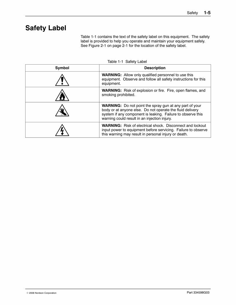
Safety Label Table 1-1 contains the text of the safety label on this equipment. The safetylabel is provided to help you operate and maintain your equipment safely.See Figure 2-1 on page 2-1 for the location of the safety label.
Table 1-1 Safety Label
Symbol Description
WARNING: Allow only qualified personnel to use thisequipment. Observe and follow all safety instructions for thisequipment.
WARNING: Risk of explosion or fire. Fire, open flames, andsmoking prohibited.
WARNING: Do not point the spray gun at any part of yourbody or at anyone else. Do not operate the fluid deliverysystem if any component is leaking. Failure to observe thiswarning could result in an injection injury.
WARNING: Risk of electrical shock. Disconnect and lockoutinput power to equipment before servicing. Failure to observethis warning may result in personal injury or death.
Safety1-6
Part 334598G03 � 2008 Nordson Corporation

Description 2-1
Part 334598G03� 2008 Nordson Corporation
Section 2Description
Introduction See Figure 2-1.
The Kinetix airless manual electrostatic high-pressure spray gunelectrostatically charges and sprays liquid coatings. The spray gun ispowered by a gun control unit and has a user-replaceable internal voltagemultiplier.
The spray gun is non-circulating and can be used with heated and unheatednon-circulating spray systems.
WARNING
Maximum Fluid Pressure103 Bar (1500 PSI)
Figure 2-1 Kinetix Airless Manual Electrostatic Spray Gun
Note: Refer to Safety Label on page 1-5 for a description of the warning labels onthe spray gun extension.

Description2-2
Part 334598G03 � 2008 Nordson Corporation
Airless DescriptionThe spray gun sprays coating materials at high pressures of up to103 bar (1500 psi). Atomization is achieved by forcing the coating materialthrough a very small nozzle orifice. This process yields better transferefficiencies and allows the spray gun to apply large quantities of coatingmaterials very quickly.
Features� adjustable air-assist air pressure and fluid flow rate
� easy disassembly for cleaning and repair
� low trigger force to reduce operator fatigue
OptionsOptions include a variety of Nordson Cross-Cut� and dome nozzles;restrictors; fluid hoses; and fittings.
Coating MaterialsThe spray guns are compatible with a wide variety of coating materialsincluding
� general solvent-based
� metallics
� high-solids
� multi-component
NOTE: The seals in the spray gun are compatible with most coatings. Ifthe coating material you use damages the seals, contact your NordsonCorporation representative for compatible replacements.
Description 2-3
Part 334598G03� 2008 Nordson Corporation
Theory of Operation See Figure 2-2.
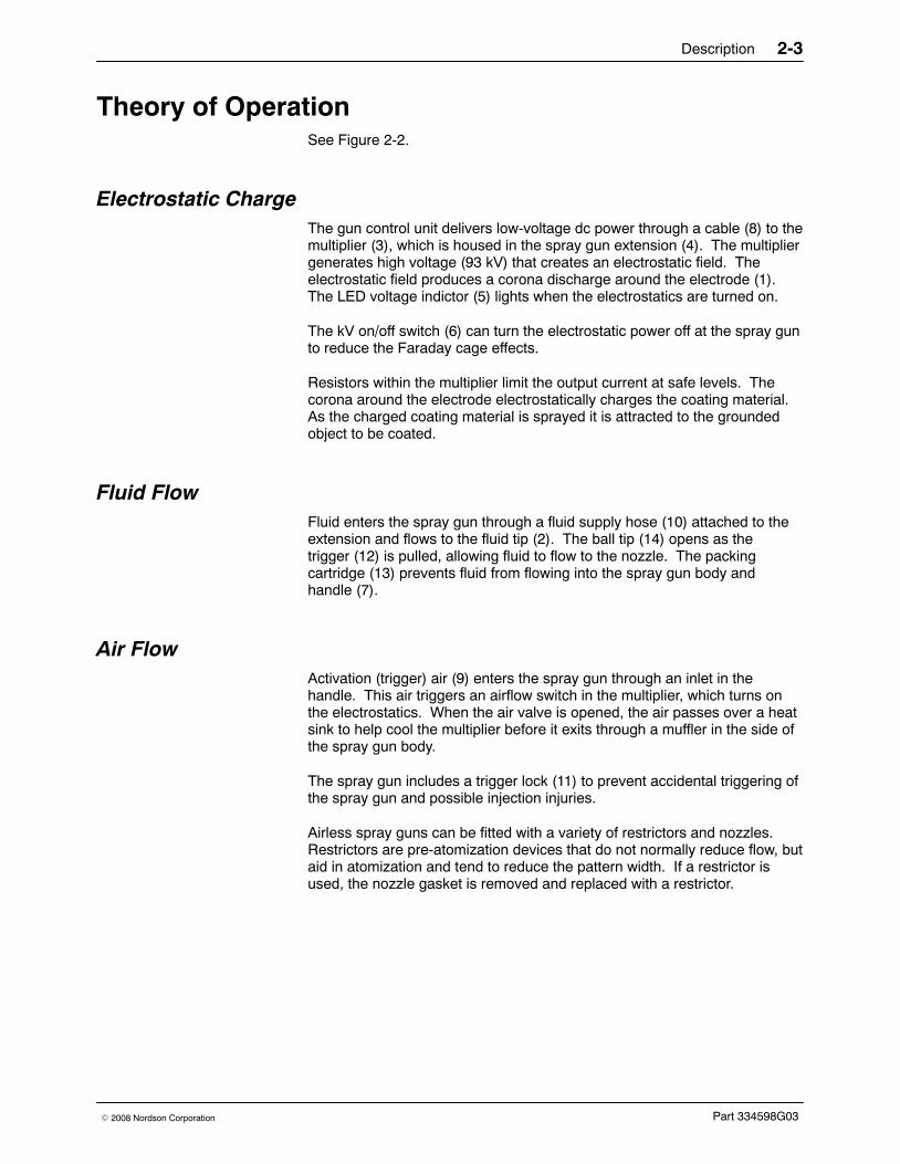
Electrostatic ChargeThe gun control unit delivers low-voltage dc power through a cable (8) to themultiplier (3), which is housed in the spray gun extension (4). The multipliergenerates high voltage (93 kV) that creates an electrostatic field. Theelectrostatic field produces a corona discharge around the electrode (1).The LED voltage indictor (5) lights when the electrostatics are turned on.
The kV on/off switch (6) can turn the electrostatic power off at the spray gunto reduce the Faraday cage effects.
Resistors within the multiplier limit the output current at safe levels. Thecorona around the electrode electrostatically charges the coating material.As the charged coating material is sprayed it is attracted to the groundedobject to be coated.
Fluid FlowFluid enters the spray gun through a fluid supply hose (10) attached to theextension and flows to the fluid tip (2). The ball tip (14) opens as thetrigger (12) is pulled, allowing fluid to flow to the nozzle. The packingcartridge (13) prevents fluid from flowing into the spray gun body andhandle (7).
Air FlowActivation (trigger) air (9) enters the spray gun through an inlet in thehandle. This air triggers an airflow switch in the multiplier, which turns onthe electrostatics. When the air valve is opened, the air passes over a heatsink to help cool the multiplier before it exits through a muffler in the side ofthe spray gun body.
The spray gun includes a trigger lock (11) to prevent accidental triggering ofthe spray gun and possible injection injuries.
Airless spray guns can be fitted with a variety of restrictors and nozzles.Restrictors are pre-atomization devices that do not normally reduce flow, butaid in atomization and tend to reduce the pattern width. If a restrictor isused, the nozzle gasket is removed and replaced with a restrictor.

Description2-4
Part 334598G03 � 2008 Nordson Corporation
Theory of Operation (contd)
713
4
12
10
9
14
Electrostatic flow
Air flow
Fluid flow
811
2
3
1
5
6
Figure 2-2 Spray Gun Components and Operation
1. Electrode2. Fluid tip3. Multiplier4. Extension5. LED voltage indicator
6. kV actuator switch7. Handle8. Electrostatic cable9. Activation (trigger) air
10. Fluid supply hose
11. Trigger lock12. Trigger13. Packing cartridge14. Ball tip

Installation 3-1
Part 334598G03� 2008 Nordson Corporation
Section 3Installation
WARNING: Allow only qualified personnel to perform the following tasks.Follow the safety instructions in this document and all other relateddocumentation.
Preparation
CAUTION: Do not overtighten parts. Failure to observe this caution willresult in equipment damage.
NOTE: Nozzles, gaskets or gaskets with restrictors, the electrode, and thePTFE retaining washer are not shipped with the spray gun and must beordered separately based on your application.
NOTE: A gasket or gasket with restrictor and the PTFE retaining washerare required. For assistance in selecting the appropriate nozzle andrestrictor for your application, contact your Nordson Corporationrepresentative.
Before installation,
� make sure you have the appropriate nozzle, gasket or gasket withrestrictor, electrode, and PTFE retaining washer for your application.
� make sure you have high-pressure fluid hoses of the correct length, ID,and materials.
WARNING: Risk of fire and/or electrical shock if the spray gun and systemcomponents are not properly grounded.
� make sure the system is properly grounded.
NOTE: Inadequately grounded parts will lose electrostatic attractionefficiency when sprayed.
� remove the spray gun, brushes, and combination tool from the box.

Installation3-2
Part 334598G03 � 2008 Nordson Corporation
Typical Airless System
WARNING: Install an approved pressure relief device set at 103 bar(1500 psi) in the fluid line to the spray gun. The fluid supply hose musthave a minimum pressure rating of 103 bar (1500 psi). Failure to observethis warning could result in equipment damage or personal injury.
Figure 3-1 shows the components of a typical airless system. Some of thecomponents shown are optional. Make sure your system containsself-relieving shutoff valves for the fluid supply.
1 2 3 4 5 6 7 8
12
1114
13
16
15
10
9
Figure 3-1 Typical Airless System
1. Spray gun2. Fluid filter3. Heater (as required)4. Pump5. Air lubricator6. Air regulator
7. Air filter8. Self-relieving shutoff valve9. Fluid supply line
10. Drain rod11. Drain valve
12. Siphon screen13. Air supply line (to controller)14. Control unit15. Gun cable16. Air supply line (to spray gun)

Installation 3-3
Part 334598G03� 2008 Nordson Corporation
Air and Fluid Hose ConnectionsSpray gun fittings accept standard Nordson hoses.
Air HoseThe air hoses supplying air to the spray gun should be no longer than7.62 m (25 ft).
Limit the number of restrictions in the air supply lines and hose to providemaximum air flow.
1. Clean the air hose fittings with a clean, dry cloth.
2. Connect the trigger air hose between the 1/4-in. tube fitting in the spraygun handle and the air supply outlet.
Fluid Hose
WARNING: The fluid hose must be a grounding-type hose with continuitybetween fittings. Without a ground, a static charge could build up in thespray gun, resulting in shocks to the operator or sparking that could cause afire. Resistance checks, from hose fitting to hose fitting, should be a part ofyour regular maintenance procedures.
As coating materials become more conductive (lower resistivity) morecurrent will bleed back through the fluid column in the fluid hose to thegrounded fitting. With a very conductive material like water, all of thecurrent will bleed to the ground and the spray gun would essentially beshorted.
A certain level of conductivity is required for electrostatics to be practical.Coating materials with resistivities of 0.75−2.0 Musually work well. Thetransfer efficiency and wrap could be reduced as coating resistivities fallbelow 0.10 M
Figure 3-2 identifies the optimum coating resistivities for electrostatics of0.75−2.0 M
Figure 3-3 charts the rapid increase of current bleeding through the fluidcolumn to ground as coating resistivity decreases.

Installation3-4
Part 334598G03 � 2008 Nordson Corporation
Fluid Hose (contd)
Best range for airspray electrostatic 0.5−3.0 range — A to E scale.
Legend:
Best range for rotary 0.10−1.0 range — C to F scale.
Best range for airless and air−assisted airless electrostatic 0.75−2.0 range — B to D scale.
NOTE: Readings outside these ranges are often acceptable.
−
−
−
MEG-OHM METER
A B
ED
F
Non-polar(Non-conductive)
Polar(Conductive)
C
PAINT RESISTIVITY METER
LOW HIGH
Figure 3-2 Resistivity Range for Coatings
Current Draw Through a One Foot Length of 0.25−in. IDFluid Tube vs. Coating Resistivity
0
20
40
60
80
100
120
0 0.1 0.2 0.3 0.4 0.5 0.6 0.7
Coating Resistivity (Megohms)
Cur
rent
Dra
w (
mic
ro−
Am
ps)
Figure 3-3 Current Draw through a One Foot Length of 0.25-in. ID Fluid Tube

Installation 3-5
Part 334598G03� 2008 Nordson Corporation
Fluid Hose Connection1. Clean the fluid hose fittings with a clean, dry cloth.
2. Connect the fluid hose(s) between the fluid delivery system outlet andthe fluid fitting that terminates at the ground bracket.
NOTE: The standard fluid hose will work well for most coating materials.The effectiveness of the electrostatics may diminish when coatingresistivities fall below 25 megohms/cm. The optional 25-ft long fluid hosewill improve the electrostatic charge by isolating the fluid column.
Gun CableWARNING: Ground all electrically conductive equipment. Ungroundedconductive equipment can store a static charge, which could ignite a fire orcause an explosion if a hot spark is discharged. Wear shoes withconductive soles such as leather, or use grounding straps to maintain aconnection to ground when working with or around electrostatic equipment.
NOTE: Refer to the gun control unit manual for more information.
See Figure 3-4. Connect the gun cable (4) to the POWER OUTPUT orGUN OUTPUT receptacle (2) on the back of the gun control unit (1).
2
1
3 4
Figure 3-4 Gun Cable Installation
1. Control unit2. Cable receptacle
3. Cable connector 4. Gun cable

Installation3-6
Part 334598G03 � 2008 Nordson Corporation
Securing the Hoses and Cables
Gun Cable� Protect the end of the gun cable so that no contaminants, oils, particles,
or solvents are carried by it into the gun control unit receptacle.
� Do not tie the cable to the machine members in areas where the cablemust move or stretch.
� Do not bend the cable around a radius of less than 15.24 cm (6 in.) atstationary points and 20.3 cm (8 in.) at flexing points.
� Do not allow the cable to become abraded around sharp corners suchas booth edges.
� Do not walk on the cable or run over it with heavy objects.
� Do not use cable ties. Use hook and loop tape to secure the cable.
� Bundle the cable with the air and fluid hoses.
Air and Fluid Hoses� Bundle the air and fluid hose together with hook and loop tape, spiral-cut
tubing, or similar devices. If you secure the hoses to a stationary objectat any point between the fluid delivery system, make sure the hoses canflex without strain.
� If desired, cover the spray gun, hoses, and other equipment in the sprayarea with a grounded conductive wrapping to keep them clean.
Nozzle and Gasket with Restrictor Installation See Figure 3-5.
WARNING: Shut off the gun control unit and ground the spray gunelectrode to remove any residual charge. Failure to observe this warningcould result in personal injury.
WARNING: Make sure the trigger lock is engaged, shut off thefluid-delivery system, and relieve the fluid pressure in the system. Failure toobserve this warning could result in an injection injury.
NOTE: Restrictors are devices that help atomize fluids. They do notnormally reduce the fluid flow but tend to reduce pattern widths.
1. Turn off the gun control unit and ground the spray gun electrode toremove any residual charge.
2. Point the spray gun into the booth or waste container and activate thespray gun to relieve residual pressure. Lock the trigger to preventinadvertent activation of the spray gun.

Installation 3-7
Part 334598G03� 2008 Nordson Corporation
3. Unscrew the retaining ring (6). Remove the retaining ring and airlesscap (5) assembly.
4. Make sure the gasket or gasket with restrictor (3) is installed in thenozzle (4).
NOTE: If you are using a gasket with restrictor, the restrictor will already beinstalled in the gasket. Make sure the gasket with restrictor is installed inthe nozzle with the flush surface toward the nozzle.
5. Install the PTFE retaining washer (2) behind the gasket to hold it inplace. The end of the fluid tip (1) can be used to help seat the gasketand washer.
1
5
4
6
3
2
7
Figure 3-5 Nozzle and Gasket with Restrictor Installation
1. Fluid tip2. PTFE retaining washer3. Gasket or gasket with restrictor
4. Nozzle5. Airless cap
6. Retaining ring7. Electrode
6. Align the slot in the nozzle with the tab in the airless cap. Make sure toline up the holes for the electrode (7).
7. Insert the electrode though the nozzle and airless cap making sure theshort leg of the electrode is inserted into the second hole in the back ofthe nozzle.
8. Make sure the airless cap rests in the groove in the bottom of theretaining ring and that it rotates freely.
9. Screw the retaining ring and cap assembly onto the extension. Hold thecap in the desired position and tighten the retaining ring until it is snug.
NOTE: The cap screws into the retaining ring and rests in a groove in thering that lets it rotate freely. Do not overtighten the cap.

Installation3-8
Part 334598G03 � 2008 Nordson Corporation

Operation 4-1
Part 334598G03� 2008 Nordson Corporation
Section 4Operation
WARNING: Allow only qualified personnel to perform the following tasks.Follow the safety instructions in this document and all other relateddocumentation.
Introduction WARNING: This equipment can be dangerous unless it is used inaccordance with the rules laid down in this manual.
WARNING: Do not exceed the maximum fluid pressure rating of103 bar (1500 psi). Failure to follow this warning may result in death orpersonal injury.
WARNING: While operating manual spray guns, make sure you aregrounded. Wear electrically conductive gloves or a grounding strapconnected to the gun handle or other true earth ground. Do not wear orcarry metallic objects such as jewelry or tools.
WARNING: High-pressure fluids are extremely hazardous. Do not pointthe spray gun at any part of your body or at anyone else. Do not operatethe fluid-delivery system if any component is leaking. Failure to observethis warning could result in an injection injury. Refer to High Pressure Fluidson page NO TAG for more information.
WARNING: The spray gun includes a trigger lock. Engage the trigger lockto prevent accidental triggering of the gun and possible injection injuries.Failure to observe this warning may result in injury.
NOTE: Read this entire section before performing any procedures.

Operation4-2
Part 334598G03 � 2008 Nordson Corporation
Introduction (contd)
Before operating the spray gun, make sure that
� the fluid tip, nozzle, gasket or gasket with restrictor, electrode, and PTFEretaining washer are correctly installed and the cap is installed andsecurely held with the retaining ring.
� all fluid connections are secure and leak-free. The fluid hose isgrounded.
� fluid delivery components are correctly installed. All conductive systemcomponents and flammable material containers are securely connectedto a true earth ground.
� the operator station and spray area are clean and free of debris.
Daily Startup
WARNING: Never operate the spray gun with a worn or damaged triggerlock. Failure to observe this warning may result in injury.
NOTE: When starting a new spray system for the first time, flush the fluiddelivery system, hose, and spray gun with a solvent compatible with thecoating material to be used. Remove the cap from the spray gun beforeflushing solvent through the spray gun. Flushing will remove contaminantsfrom the system.
1. Turn on the air supply shutoff valve. Adjust the air pressure to1.03 bar (15 psi) minimum. This air supply pressure is required toactivate the air flow switch.
NOTE: If kV is erratic, check the kV indicator. If the kV voltage indicator isflickering or is off, increase the air pressure.
2. Lock the trigger and turn on the gun control unit.
3. Pressurize the system with fluid. Refer to your pump manual for startupand operating instructions. Do not exceed 103 bar (1500 psi).
4. Turn on the fluid heater(s), if used. Refer to your heater manual foroperating instructions. Do not exceed 82 �C (180 �F).
5. Turn on the spray booth exhaust fans.
6. Check the fluid-delivery system for leaks.

Operation 4-3
Part 334598G03� 2008 Nordson Corporation
7. Point the spray gun into the booth, unlock the trigger, and trigger thespray gun to start spraying.
NOTE: Triggering the spray gun should produce atomized spray and tun onthe voltage multiplier. The red kV indicator should illuminate on the back ofthe spray gun. Adjust the fluid pressure to obtain the desired atomizationand spray pattern. Refer to Spray Pattern and Atomization Adjustments inthis section.
8. Use a Nordson kV meter to read the kV output. Use this informationand the values from Electrostatic Troubleshooting as a baseline whentroubleshooting the electrostatic system.
NOTE: Refer to Electrostatic Troubleshooting on page 6-4 for moreinformation.
Spray Pattern and Atomization AdjustmentsObtaining the correct spray pattern, coating material atomization, andtransfer efficiency for your application requires a combination of operatorexperience and experimentation. To obtain the best results, perform thefollowing tasks.
WARNING: Shut off the power supply. Ground the spray gun’s electrode toremove any residual charge. Failure to observe this warning could result inpersonal injury.
WARNING: Shut off the fluid-delivery system and relieve system fluidpressure before removing nozzles or restrictors. Failure to observe thewarning could result in an injection injury.
Adjust the coating material atomization by increasing or decreasing the fluidpressure. If these adjustments do not improve the atomization, install agasket with restrictor. If the gasket with restrictor does not improveatomization, change the nozzle, restrictor, or coating material viscosity.

Operation4-4
Part 334598G03 � 2008 Nordson Corporation
Shutdown
WARNING: Shut off the power supply. Ground the spray gun’s electrode toremove any residual charge. Failure to observe this warning could result inpersonal injury.
WARNING: Before installing or changing nozzles or restrictors, shut off thefluid-delivery system and relieve the fluid pressure in the system. Failure toobserve this warning could result in an injection injury.
Short-TermFor short-term breaks in production, no shutdown procedures arenecessary. Lock the trigger air and wipe the cap and fluid tip with a cleancloth dampened with a compatible solvent.
Long-Term1. Shut off the power supply.
2. Shut off the fluid-delivery system.
3. Trigger the spray gun into a waste container to relieve system fluid andair pressures.
4. Remove the nozzle, gasket or gasket with restrictor, electrode, andPTFE retaining washer.
5. Flush the fluid-delivery system, fluid hose(s), and spray gun with acompatible solvent.
Refer to the Maintenance section for recommended flushing and cleaningprocedures.
Multi-Component Coatings
CAUTION: Leaving the coating material in the spray gun longer than theindicated pot-life may clog the spray gun and require disassembly andreplacement of major spray gun components.
Refer to the coating material pot-life information to determine the propershutdown procedures.

Maintenance 5-1
Part 334598G03� 2008 Nordson Corporation
Section 5Maintenance
WARNING: Allow only qualified personnel to perform the following tasks.Follow the safety instructions in this document and all other relateddocumentation.
IntroductionThe spray gun requires very little routine maintenance beyond cleaning.For best results, keep the spray gun as clean as practical.
NOTE: Three spray gun covers are provided with each spray gun. Keepingthe spray gun clean can minimize wrapback and improve transfer efficiency.
Daily WARNING: Shut off the gun control unit and ground the spray gunelectrode to remove any residual charge. Failure to observe this warningcould result in personal injury.
WARNING: Shut off the fluid-delivery system and relieve the fluid pressurein the system. Failure to observe this warning could result in an injectioninjury.
Perform the following procedure at the end of each work shift:
1. Shut down the fluid-delivery system and relieve all fluid and airpressures.
2. Trigger the spray gun into the booth or a grounded waste container torelieve any residual pressure. Lock the trigger.
3. Turn off the gun control unit and ground the spray gun electrode toremove any residual charge.
WARNING: Before changing nozzles or restrictors, shut down the systemand relieve all fluid and air pressures. Failure to observe this warning couldresult in injury.

Maintenance5-2
Part 334598G03 � 2008 Nordson Corporation
Daily (contd)
CAUTION: Use a non-conductive solvent compatible with your coatingmaterial. Cleaning with conductive solvents can result in carbon trackingand loss of kV.
CAUTION: Use only a Nordson cleaning brush to clean the fluid tip andcap. Using metal tools will damage the fluid tip and airless air cap, causingfaulty spray patterns.
CAUTION: Avoid cleaning the spray gun with pressurized solvents.Spraying with pressurized solvents can force the solvent into spray guncavities, potentially damaging spray gun components.
4. Clean the nozzle and restrictor, if used.
a. Remove the retaining ring and airless air cap.
b. Remove the nozzle, PTFE retaining washer, and gasket or gasketwith restrictor, if used. Soak the nozzle and restrictor in a compatiblesolvent to loosen any cured coating material. Use an ultrasoniccleaner if necessary.
c. Clean the nozzle and restrictor with a nozzle cleaning brush.
d. Examine the nozzle and restrictor orifices with a magnifying lens. Ifthe orifices are clogged, use a broach or probe to clean them. Insertthe broach or probe against the direction of flow. Do not use atwisting or sawing motion to clean the orifices.
e. Blow out the orifices with an OSHA-approved blowgun, against thedirection of fluid flow.
5. Clean the fluid tip and extension with a soft-bristled brush and acompatible solvent.
NOTE: Pointing the spray gun down at a slight angle will preventsolvents from entering the air passages and possibly damaging the airseals. Most air seals are not universally compatible with all solvents andcan be damaged.
6. Clean the spray gun extension frequently with a clean cloth dampenedwith solvent. Do not soak the spray gun in solvent.
NOTE: Take special care when cleaning the spray gun with solvents.Using excessive amounts of solvent can allow solvent to leak into thespray gun and damage the multiplier. If the gun requires extensivecleaning, remove the multiplier. Refer to Multiplier Replacement onpage 7-12.
7. Dry the fluid tip, cap, and spray gun with low-pressure air from anOSHA-approved blowgun.
Maintenance 5-3
Part 334598G03� 2008 Nordson Corporation
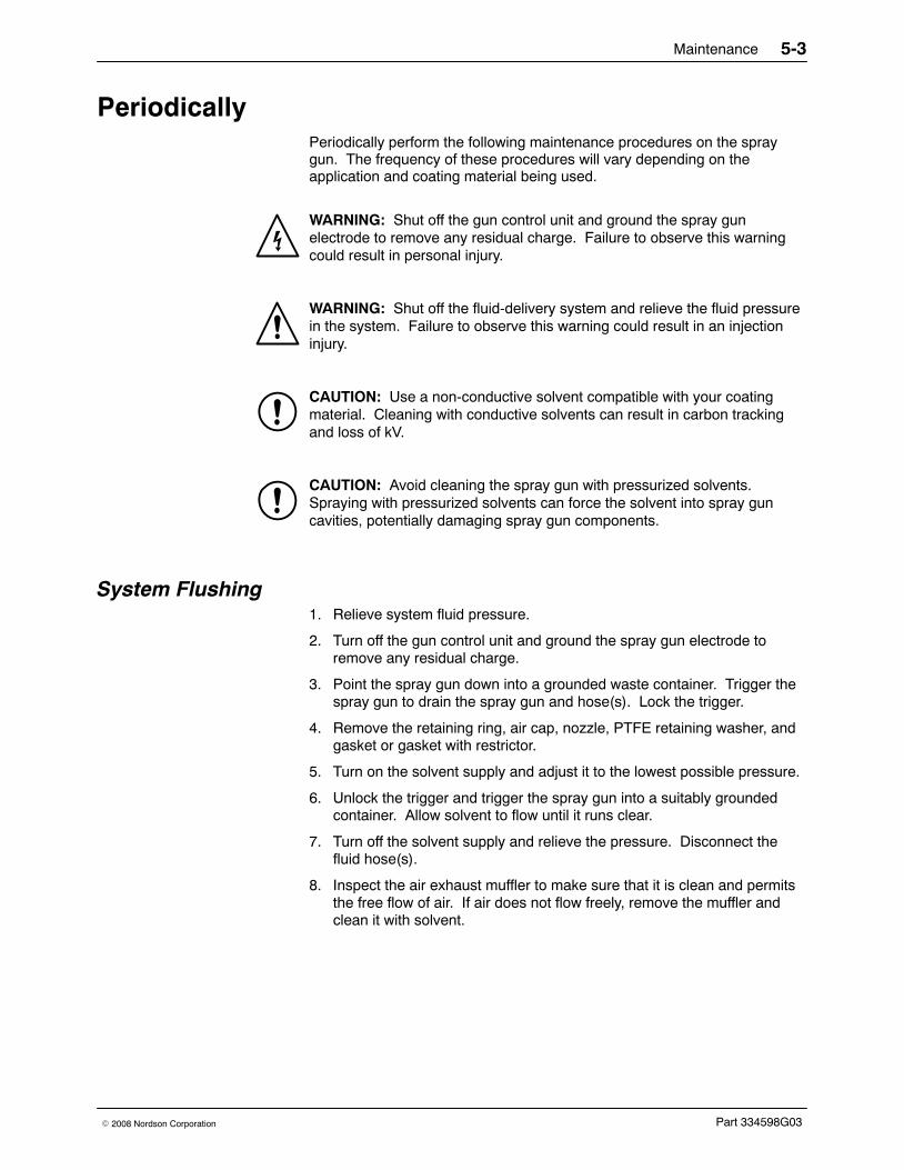
PeriodicallyPeriodically perform the following maintenance procedures on the spraygun. The frequency of these procedures will vary depending on theapplication and coating material being used.
WARNING: Shut off the gun control unit and ground the spray gunelectrode to remove any residual charge. Failure to observe this warningcould result in personal injury.
WARNING: Shut off the fluid-delivery system and relieve the fluid pressurein the system. Failure to observe this warning could result in an injectioninjury.
CAUTION: Use a non-conductive solvent compatible with your coatingmaterial. Cleaning with conductive solvents can result in carbon trackingand loss of kV.
CAUTION: Avoid cleaning the spray gun with pressurized solvents.Spraying with pressurized solvents can force the solvent into spray guncavities, potentially damaging spray gun components.
System Flushing1. Relieve system fluid pressure.
2. Turn off the gun control unit and ground the spray gun electrode toremove any residual charge.
3. Point the spray gun down into a grounded waste container. Trigger thespray gun to drain the spray gun and hose(s). Lock the trigger.
4. Remove the retaining ring, air cap, nozzle, PTFE retaining washer, andgasket or gasket with restrictor.
5. Turn on the solvent supply and adjust it to the lowest possible pressure.
6. Unlock the trigger and trigger the spray gun into a suitably groundedcontainer. Allow solvent to flow until it runs clear.
7. Turn off the solvent supply and relieve the pressure. Disconnect thefluid hose(s).
8. Inspect the air exhaust muffler to make sure that it is clean and permitsthe free flow of air. If air does not flow freely, remove the muffler andclean it with solvent.
Maintenance5-4
Part 334598G03 � 2008 Nordson Corporation
Spray Gun CleaningNOTE: Trigger the spray gun to pull the ball tip off of the seat beforeremoving the fluid tip. This will prevent damage to the ball tip and the seat.
CAUTION: Do not clean the multiplier or the gun cable with solvent.Failure to observe this caution could result in equipment damage.
Routine Cleaning1. Remove the fluid tip.
2. Disconnect the air hose and fluid hose(s).
CAUTION: Use a non-conductive solvent compatible with your coatingmaterial. Cleaning with conductive solvents can result in carbon trackingand loss of kV.
CAUTION: Use only a Nordson cleaning brush to clean the fluid tip andcap. Using metal tools will damage the fluid tip and airless air cap, causingfaulty spray patterns.
3. Point the spray gun down and clean the front of the spray gun with asoft-bristled brush dampened with a compatible cleaning solvent.
NOTE: Pointing the spray gun down at a slight angle will preventsolvents from entering the air passages and possibly damaging the airseals. Most air seals are not universally compatible with all solvents andcan be damaged.
4. Dampen a soft cloth with a compatible cleaning solvent. Point the spraygun downward and clean the exterior.
NOTE: Take special care when cleaning the spray gun with solvents.Using excessive amounts of solvent can allow solvent to leak into thespray gun and damage the multiplier. If the gun requires extensivecleaning, remove the multiplier. Refer to Multiplier Replacement onpage 7-12.
5. Clean the fluid tip, cap, and retaining ring with a soft-bristled brush and acompatible solvent. Remove the O-rings and back-up ring and soak thefluid tip in solvent if necessary.
6. Install the retaining ring, airless air cap, nozzle, PTFE retaining washer,gasket or gasket with restrictor, and fluid tip. Pull on the trigger to retractthe ball tip before installing the fluid tip.
7. Install the trigger air hose and fluid hose(s).

Maintenance 5-5
Part 334598G03� 2008 Nordson Corporation
Extensive Cleaning
CAUTION: Never soak or vigorously clean the spray gun with the multiplierinstalled.
For more extensive cleaning, disassemble the spray gun and clean eachpart. Once disassembled, the extension and handle can be soaked insolvent and scrubbed. Remove all the seals before soaking any parts insolvent.
Electrostatic System ChecksUse a Nordson non-loading kV meter to perform checks on the electrostaticsystem, and a megohmmeter to check the resistance values on the spraygun. These checks ensure that the operator, electrostatic spray gun,electrostatic power supply, and all conductive material within the spray areaare connected to a true earth ground. Proper grounding is essential forefficient operation and prevention of a buildup and subsequent discharge ofan electrostatic charge that could ignite combustible material within thespray area.
Make sure the electrostatic equipment has and maintains the properresistance values. Proper resistance values are important to maintain theequipment within designed current outputs. The resistance values may varyover a period of time due to several conditions; for example, a buildup ofresidue in the spray area and degradation of electrical components thathave been exposed to high voltages may occur.
Maintenance5-6
Part 334598G03 � 2008 Nordson Corporation

Troubleshooting 6-1
Part 334598G03� 2008 Nordson Corporation
Section 6Troubleshooting
WARNING: Allow only qualified personnel to perform the following tasks.Follow the safety instructions in this document and all other relateddocumentation.
Introduction
WARNING: Shut off the gun control unit and ground the spray gunelectrode to remove any residual charge. Failure to observe this warningcould result in personal injury.
These procedures cover only the most common problems that you mayencounter. If you cannot solve the problem with the information given here,contact your local Nordson representative for help.
This section contains troubleshooting procedures for
� common spray gun problems;
� spray pattern and film-build faults; and
� electrostatics.
When multiple causes exist for a problem, they are listed in order ofimportance.

Troubleshooting6-2
Part 334598G03 � 2008 Nordson Corporation
Common Problems
Problem Possible Cause Corrective Action
1. Spray gun spitting Dirty or worn ball tip or fluid tip Clean or replace the ball tip and fluidtip.
Air bubbles in fluid stream Bleed air from the fluid deliverysystem. Check for leaks in the fluiddelivery system or excessiveagitation in the fluid reservoir.
Fluid pressure too low Increase the fluid pressure.
2. Fluid leaking aroundthe nozzle or retainingring
Worn or damaged nozzle gasketor gasket with restrictor
Replace the nozzle gasket or gasketwith restrictor.
Worn or damaged air piston orother air seals
Replace the piston O-rings or otherseals.
3. Fluid leaking fromrear of extension
Worn or damaged packingcartridge O-ring
Replace the O-ring and back-up ring.
Worn or damaged packingcartridge
Replace the packing cartridge(packing cartridge cannot berepaired).
4. Low or erratic fluidflow
Fluid delivery system malfunction Check the fluid delivery system (airand fluid).
Blockage within spray gun, fluidhose, or fluid system
Flush the system. If necessary,repair or replace clogged or damagedcomponents.
Low fluid pressure WARNING: Do not exceed themaximum fluid pressure rating of 103bar (1500 psi). Failure to observethis warning may result in death orpersonal injury.
Slowly increase the fluid pressureuntil the desired fluid flow is obtained.
Fluid too viscous Lower the viscosity by adding solventor increasing the fluid temperature.
5. Coarse spray Fluid too viscous Lower the viscosity by adding solventor increasing fluid temperature.
Solvent evaporates too quickly Use slower evaporating solvent.Contact your material supplier.
Clogged or damaged nozzle,restrictor, or fluid tip
Clean and inspect the nozzle,restrictor, and fluid tip. Replace themif they are damaged.
Gun control unit is off Turn on the gun control unit.
6. Excessive bounceback
Fluid pressures too high Reduce the fluid pressures.
7. Dry spray Spray gun held too far away fromsubstrate
Move the spray gun closer to thesubstrate.

Troubleshooting 6-3
Part 334598G03� 2008 Nordson Corporation
Spray Pattern/Film Build TroubleshootingFigure 6-1 illustrates common spray pattern and film build faults.
Problem Possible Cause Corrective Action
1. Fluttering orspitting (1)
Air in fluid line Check for air leaks in the system.
Fluid pressure too low Increase the fluid pressure.
2. Irregular pattern (2) Partially clogged nozzle orifice Remove the nozzle and clean.
Worn or damaged nozzle Replace the nozzle.
3. Tails in pattern (3) Fluid pressure too low Increase the fluid pressure.
1 2 3
Figure 6-1 Common Spray Pattern Faults
1. Fluttering or spitting 2. Irregular pattern 3. Tails in pattern

Troubleshooting6-4
Part 334598G03 � 2008 Nordson Corporation
Electrostatic Troubleshooting
Problem Possible Cause Corrective Action
1. Loss of wrap, poortransfer efficiency
Low electrostatic voltage Increase the voltage.
Resistor or multiplier failure Check the multiplier/tip resistorassembly with a megohmmeter for277−340 megohms at 500 volts. Ifthe reading is out of range, check theresistor tip separately. The tipresistor should measure33.3−36.8 megohms. Refer toMultiplier Continuity and ResistanceCheck on page 6-5.
Poorly grounded parts Check the conveyor chain, rollers,and part hangers for paint buildup.The resistance between the partsand the ground must be 1 megohmor less. 500 ohms or less isrecommended for best results.
2. No kV output fromspray gun
KV on/off switch in off position Check the position of the kV on/offswitch. Switch to the on position ifnecessary.
Damaged gun cable Check the continuity of the cablewires, from pin to pin. Replace thecable if any opens or shorts arefound. Refer to Gun Cable ContinuityCheck on page 6-6.
Malfunctioning voltage multiplier Check the continuity and resistanceof the multiplier with a megohmmeterfor 277−340 megohms at 500 volts.No burn throughs or arc tracksshould be visible on any parts. Referto Multiplier Continuity andResistance Check on page 6-5.
Failed tip resistor Check the resistor with amegohmmeter for33.3−36.8 megohms at 500 volts.
Malfunctioning gun control unit Check for 21 Vdc between cable endconnectors. Refer to Gun CableContinuity Check on page 6-6.
Insufficient air flow to activate theelectrostatics
Increase the air pressure.
Clogged or dirty muffler Clean or replace the muffler.
Air pressure too low Increase the air pressure.
Continued...

Troubleshooting 6-5
Part 334598G03� 2008 Nordson Corporation
Problem Possible Cause Corrective Action
3. %kV reading oncontroller incorrect
Input voltage switch is not incorrect position
If the input voltage is120 V, theswitch in the controller must be set tothe 120 V position. Refer to theKinetix Manual Gun Power Supplymanual for more information.
4. Electrostatics will notshut off when triggeris released
Air leak in air hose Check the air hose and fittings forleaks. Tighten the fittings or replacethe hose.
Air valve seat worn or damaged Remove the air valve and inspect thesealing surface. Replace the airvalve if worn or damaged.
Multiplier Continuity and Resistance CheckSee Figure 6-2.
The multiplier should measure 277−340 megohms at 500 volts.
1. Connect the earth ground probe (common end) of the megohmmeter tothe contact spring (2).
2. Connect the other probe of the megohmmeter to one of the three pins(1) on the end of the multiplier.
NOTE: The polarity of the voltage multiplier requires that the megohmmeterbe connected correctly to obtain a good reading.
If the multiplier does not measure correctly, replace the multiplier. Refer toMultiplier Replacement on page 7-12.
21
Figure 6-2 Multiplier Continuity and Resistance Check
1. Pins 2. Contact spring

Troubleshooting6-6
Part 334598G03 � 2008 Nordson Corporation
Gun Cable Continuity CheckSee Figure 6-3.
Use an ohmmeter to check the cable continuity at the connector terminalslisted in Table 6-1.
NOTE: If the continuity check fails make sure the kV on/off switch is in theon position.
Table 6-1 Spray Gun Cable Continuity Check
Control UnitConnector Spray Gun Connector Position
1 Open
2 2 Closed
3 3 Closed
4 1 Closed
5 Open
6 Bracket Closed
1
2
3
1
2
3
4
5
6
Figure 6-3 Gun Cable Continuity Check

Repair 7-1
Part 334598G03� 2008 Nordson Corporation
Section 7Repair
WARNING: Allow only qualified personnel to perform the following tasks.Follow the safety instructions in this document and all other relateddocumentation.
WARNING: Shut off the power supply. Ground the spray gun’s electrode toremove any residual charge. Failure to observe this warning could result inpersonal injury.
WARNING: Shut down the system and relieve all fluid and air pressuresbefore performing these procedures. Failure to observe this warning couldresult in injection injury.
WARNING: Use only Nordson replacement parts to repair the spray gun.Deviating from the repair instructions, using unauthorized parts, or makingunathorized modifications can result in personal injury or death and/or theloss of approvals by agencies such as Factory Mutual ResearchCorporation (FM) or the Canadian Standards Association (CSA).
CAUTION: Do not overtighten threaded parts. Failure to observe thiscaution will result in equipment damage.
NOTE: Tighten all fittings until snug or to the specified torques. Becausethe spray gun uses O-ring seals, further tightening provides no benefit andcould damage plastic threads.
NOTE: The numeric callouts in this section match the item numbers in thespray gun parts list. Refer to the Parts section for complete partdescriptions and ordering information. Items in the repair section that arenot listed in the spray gun part lists are identified with alphabetic callouts.

Repair7-2
Part 334598G03 � 2008 Nordson Corporation
Tools/Supplies RequiredBefore beginning any of the repair tasks described in this section, makesure you have the following tools and supplies:
� See Figure 7-1: Combination tool provided with your spray gun
� 5/32-in. hex wrench
� Small flat-blade screwdriver
� Phillips-head screwdriver
� Service kits and replacement parts
� Removeable threadlocking adhesive
� Dielectric grease
� PTFE grease lubricant (MagnaLube� G) or equivalant PTFE-basedlubricant
NOTE: Refer to the Parts section for service kits and replacement parts.
A
BC
D
Figure 7-1 Combination Tool
A. ScrewdriverB. Packing cartridge tool
C. Fluid tip toolD. Hose tool
Nozzle, Restrictor, and Fluid Tip ReplacementSee Figure 7-2.
1. Turn off the gun control unit and ground the spray gun electrode toremove any residual charge.
2. Flush the fluid-delivery system, hoses, and spray gun.
3. Turn off the fluid-delivery system. Relieve system fluid pressures. Pointthe spray gun into the booth or grounded container and activate it torelieve any residual pressure.
4. Disconnect the fluid hose from the spray gun. Move the spray gun to aclean, dry, flat surface.

Repair 7-3
Part 334598G03� 2008 Nordson Corporation
5. Unscrew the retaining ring (1) and airless air cap (2) assembly from theextension.
6. Remove the nozzle (A), PTFE retaining washer (D), electrode (C), andgasket (B) or gasket with restrictor, if used. Do not lose the gasket.Clean the nozzle and restrictor as described on page 5-2.
7. Pull the trigger all the way back to retract the ball tip (15). Place the hexon the combination tool over the hex on the fluid tip (3) and unscrew itfrom the extension.
8. Make sure the O-ring (6) and conductive back-up ring (4) are installedon the new fluid tip, with the O-ring toward the rear of the fluid tip.Lubricate the O-ring with O-ring grease.
CAUTION: Do not overtighten threaded parts. Failure to observe thiscaution will result in equipment damage.
9. Pull the trigger all the way back to retract the ball tip. Screw the newfluid tip in the extension. Tighten the fluid tip snugly.
10. Install the nozzle, electrode, PTFE retaining washer, and gasket orgasket with restrictor and then securely hand tighten the retaining ringand airless air cap assembly onto the extension.
1
B
3
615
2
A
4
5
C
D
Figure 7-2 Nozzle, Restrictor, and Fluid Tip Replacement
1. Retaining ring2. Airless air cap3. Fluid tip4. Conductive back-up ring
5. Conductive ring6. O-ring
15. Ball tipA. Nozzle
B. Gasket or gasket with restrictorC. ElectrodeD. PTFE retaining washer

Repair7-4
Part 334598G03 � 2008 Nordson Corporation
Trigger Lock ReplacementSee Figure 7-3.
WARNING: Never operate the spray gun with a worn or damaged triggerlock. Failure to observe this warning could result in an injection injury.
1. Drive the pin (27) out of the trigger lock (26) and handle (19) with asmall dowel pin.
2. Hold the new trigger lock in place and drive the new pin through the lockand handle holes. The pin should be approximately flush with thetrigger lock surfaces.
26
27
19
Figure 7-3 Trigger Lock Replacement
19. Handle26. Trigger lock
27. Pin
Air Inlet Fitting Replacement 1. See Figure 7-4. Remove the screws (30, 41) to remove the back cover
(45) from the handle and ground bracket (A).
2. Remove the two screws (52) that attach the fluid hose fitting (D) to theground bracket. Remove the fluid hose from the ground bracket.
3. Slowly pull the back cover away from the handle so you do notdisconnect the cable connector (B) from the multiplier connector (C) orpull on the kV actuator switch wires.
NOTE: The cable will be secured in ribbed slots in the back of the spraygun’s handle.
4. Unscrew the old air inlet fitting (31) from the handle base and replace itwith the new air inlet fitting. Tighten the fitting finger tight.

Repair 7-5
Part 334598G03� 2008 Nordson Corporation
5. Install the bracket over the fitting hex. Tighten or loosen the air inletfitting slightly to align the fitting with the hex in the bracket.
NOTE: Make sure the cable is snapped into the ribbed slots in the back ofthe handle.
CAUTION: Be careful not to pinch the cables between the handle and theback cover as the back cover is tightened.
6. Secure the bracket to the handle and back cover using the twoscrews (30).
7. Secure the fluid hose within the ground bracket (A) with the twoscrews (52).
8. Install the back cover using the three screws (41).
41
30
C
B
45
41
30
31
A
52
D
Figure 7-4 Air Inlet Fitting Replacement
30. Screws31. Air inlet fitting/male connector41. Screws45. Back cover52. Screws
A. Ground bracketB. Cable connectorC. Multiplier connectorD. Fluid hose fitting

Repair7-6
Part 334598G03 � 2008 Nordson Corporation
Ball Tip and Packing Cartridge Replacement CAUTION: If the packing cartridge leaks, it is important to thoroughly cleanthe packing cartridge bore in the extension with a compatiblenon-conductive solvent to remove any residual coating material. Failure todo so may result in loss of kV.
CAUTION: Do not overtighten threaded parts. Failure to observe thiscaution may result in equipment damage.
The Kinetix spray gun is shipped with the standard gold packing cartridge.This durable packing cartridge is appropriate for most coating materials.Use the optional PTFE packing cartridge with harsh chemical solvents suchas MEK.
The only serviceable parts of the packing cartridge are the external O-ringand back-up ring. If replacing the O-ring and back-up ring does not stop thepacking cartridge from leaking, you must replace the packing cartridge.
The ball tip is not a component of the packing cartridge. You must order thethe ball tip separately.
Preparation1. Turn off the gun control unit and ground the spray gun electrode to
remove any residual charge.
2. Flush the fluid-delivery system, hoses, and spray gun.
3. Turn off the fluid-delivery system. Relieve system fluid pressures.
4. Point the spray gun into the booth or grounded container and activate itto relieve any residual pressure.
5. Disconnect the fluid hose from the spray gun. Move the spray gun to aclean, dry, flat surface.
Spray Gun DisassemblySee Figure 7-5.
1. Remove the nozzle, restrictor, PTFE retaining washer, electrode, gasketor gasket with restrictor, and fluid tip as described in Nozzle, Restrictor,and Fluid Tip Replacement on page 7-2.
2. Remove the two screws (52) that attach the fluid hose fitting (B) to theground bracket (A). Remove the fluid hose from the ground bracket.
3. Remove the two pivot screws (28) and the trigger (29).
4. Using a 5/32-in. hex wrench, remove the four socket head screws (8) toremove the extension (7) from the handle (19). Do not lose the twoface-seal O-rings (38) or the large face-seal O-ring (9) installed in thehandle.
Repair 7-7
Part 334598G03� 2008 Nordson Corporation
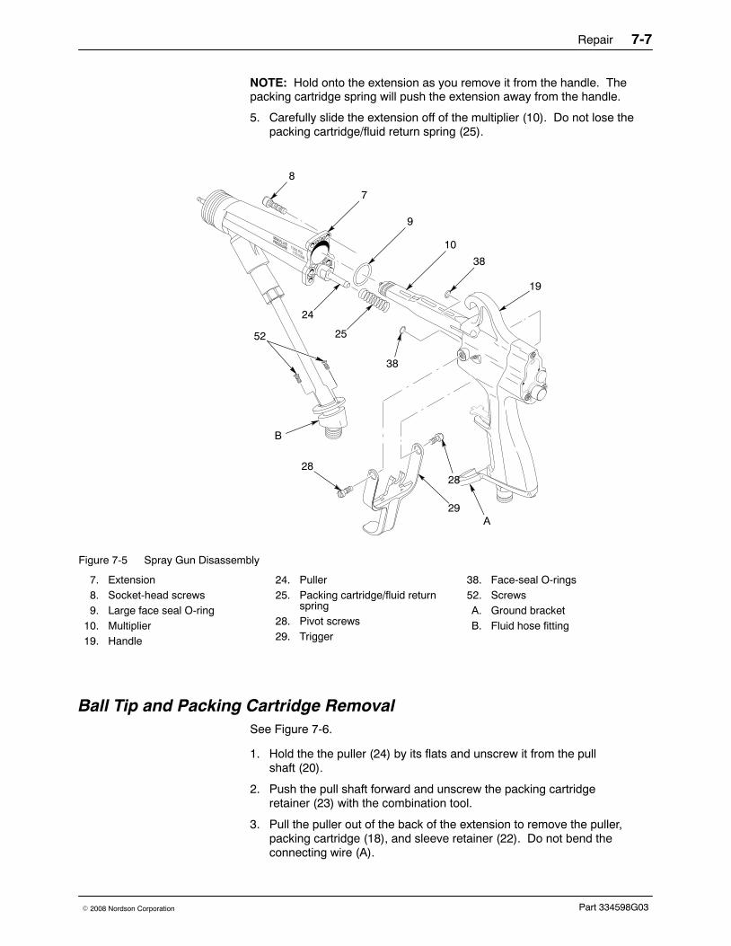
NOTE: Hold onto the extension as you remove it from the handle. Thepacking cartridge spring will push the extension away from the handle.
5. Carefully slide the extension off of the multiplier (10). Do not lose thepacking cartridge/fluid return spring (25).
8
7
24
19
2828
29
9
10
38
A
25
38
B
52
Figure 7-5 Spray Gun Disassembly
7. Extension8. Socket-head screws9. Large face seal O-ring
10. Multiplier19. Handle
24. Puller25. Packing cartridge/fluid return
spring28. Pivot screws29. Trigger
38. Face-seal O-rings52. ScrewsA. Ground bracketB. Fluid hose fitting
Ball Tip and Packing Cartridge Removal See Figure 7-6.
1. Hold the the puller (24) by its flats and unscrew it from the pullshaft (20).
2. Push the pull shaft forward and unscrew the packing cartridgeretainer (23) with the combination tool.
3. Pull the puller out of the back of the extension to remove the puller,packing cartridge (18), and sleeve retainer (22). Do not bend theconnecting wire (A).
Repair7-8
Part 334598G03 � 2008 Nordson Corporation
Ball Tip and Packing Cartridge Removal (contd)
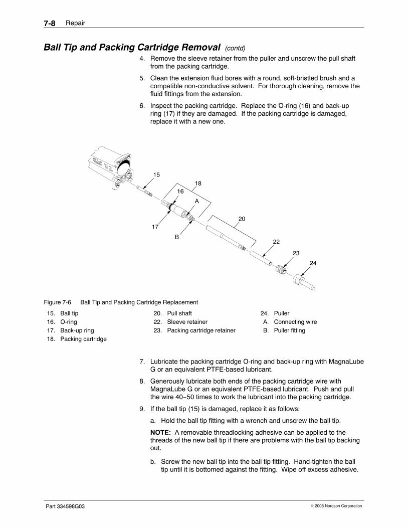
4. Remove the sleeve retainer from the puller and unscrew the pull shaftfrom the packing cartridge.
5. Clean the extension fluid bores with a round, soft-bristled brush and acompatible non-conductive solvent. For thorough cleaning, remove thefluid fittings from the extension.
6. Inspect the packing cartridge. Replace the O-ring (16) and back-upring (17) if they are damaged. If the packing cartridge is damaged,replace it with a new one.
16
A
15
20
22
23
24
18
17
B
Figure 7-6 Ball Tip and Packing Cartridge Replacement
15. Ball tip16. O-ring17. Back-up ring18. Packing cartridge
20. Pull shaft22. Sleeve retainer23. Packing cartridge retainer
24. PullerA. Connecting wireB. Puller fitting
7. Lubricate the packing cartridge O-ring and back-up ring with MagnaLubeG or an equivalent PTFE-based lubricant.
8. Generously lubricate both ends of the packing cartridge wire withMagnaLube G or an equivalent PTFE-based lubricant. Push and pullthe wire 40−50 times to work the lubricant into the packing cartridge.
9. If the ball tip (15) is damaged, replace it as follows:
a. Hold the ball tip fitting with a wrench and unscrew the ball tip.
NOTE: A removable threadlocking adhesive can be applied to thethreads of the new ball tip if there are problems with the ball tip backingout.
b. Screw the new ball tip into the ball tip fitting. Hand-tighten the balltip until it is bottomed against the fitting. Wipe off excess adhesive.

Repair 7-9
Part 334598G03� 2008 Nordson Corporation
Ball Tip and Packing Cartridge InstallationSee Figure 7-6.
NOTE: Make sure all residual coating material has been removed from allparts before installing.
1. Apply a removable threadlocking adhesive to the threads of the packingcartridge puller fitting (B).
2. Screw the pull shaft (20) onto the packing cartridge (18).
3. Apply a liberal amount of dielectric grease to the puller fitting and thepull shaft then insert the packing cartridge assembly and pull shaft intothe extension from the back.
4. Apply a liberal amount of dielectric grease to the outside of the sleeveretainer (22) then slide the sleeve retainer over the pull shaft and push itdown into the fluid bore.
5. Generously lubricate the end of the pull shaft and the inside of thepacking cartridge retainer (23) with MagnaLube G or an equivalentPTFE-based lubricant.
6. Apply a thin coating of dielectric grease to the threads of the packingcartridge retainer then screw the packing cartridge retainer into theextension.
7. Push the pull shaft forward and tighten the packing cartridge retainerwith the combination tool hand-tight.
8. Wipe off excess dielectric grease.
9. Apply a removable threadlocking adhesive to the threads of the pullshaft and screw the puller onto the pull shaft.
Spray Gun Assembly See Figure 7-5.
1. Make sure that the multiplier (10) is clean and well lubricated withdielectric grease. Grease the front 1/3 of the multiplier and its contactspring if necessary.
2. Generously lubricate the outside diameter of the puller (24) and thepacking cartridge /fluid return spring (25) with MagnaLube G or anequivalent PTFE-based lubricant.
3. Generously lubricate the inside of the fluid return spring bore in thehandle with MagnaLube G or an equivalent PTFE-based lubricant.
4. Insert the packing cartridge/fluid return spring and the end of the pullerinto the handle trigger bore and mate together the handle (19) and theextension (7).
5. Secure the extension to the handle with the four socket-head screws (8).Tighten the screws to 1.36−1.58 Nm (12−14 in.-lb).

Repair7-10
Part 334598G03 � 2008 Nordson Corporation
Spray Gun Assembly (contd)
6. Insert the pivot screws (28) through the holes in the trigger (29) and intothe greased insert in the handle. Make sure the trigger forks engage thepull shaft. Tighten the screws to 0.9−1.13 Nm (8−10 in.-lb).
NOTE: Pull the trigger and make sure it presses the air valve stem into thehandle and pulls the ball tip into the spray gun.
7. Install the retaining ring, air cap, nozzle, PTFE retaining washer,electrode, gasket or gasket with restrictor, and fluid tip as described inNozzle, Restrictor, and Fluid Tip Replacement on page 7-2.
8. Secure the fluid hose within the ground bracket (A) with the twoscrews (52).
Air Valve Replacement
CAUTION: A worn or damaged air valve could result in an air leak thattriggers on the electrostatics. Replace a worn or damaged air valveimmediately.
Back Cover Removal1. See Figure 7-7. Remove the two screws (52) that attach the fluid hose
fitting (D) to the ground bracket (A). Remove the fluid hose from theground bracket.
2. Remove the screws (30, 41) to remove the back cover (45) from thehandle and ground bracket.
3. Slowly pull the back cover away from the handle so you do notdisconnect the cable connector (B) from the multiplier connector (C) orpull on the kV actuator switch wires.
NOTE: The cable is secured in ribbed slots in the back of the handle.
Air Valve Removal1. See Figure 7-7. Remove the air valve plug (48) with the combination
tool. Inspect the O-ring (49). Replace it if it is damaged.
2. Remove the spring (50) from the handle. Do not lose the spring.
NOTE: The air valve stem may come out with the spring. If it does not,push it out from the trigger side of the handle. Do not use any tools to forcethe stem; you may damage the U-cup seal or stem bore.
3. Inspect the air valve stem (51). Replace the air valve stem if theelastomeric seat is damaged or the stem is worn or damaged.

Repair 7-11
Part 334598G03� 2008 Nordson Corporation
NOTE: If there is no damage to the air valve stem, and air does not leakfrom the stem bore when the trigger is pulled, you should not have toreplace the U-cup seal.
4. If necessary, remove and replace the U-cup seal (36):
a. Use a small pick to pull the U-cup seal out of the handle.
b. Install a new U-cup seal on the air valve stem with the U facingoutward. Carefully insert the stem into the stem bore and seat theU-cup into the recess surrounding the stem bore.
c. Remove the air valve stem. Use the blunt end of a dowel with alarger diameter than the inside diameter of the U-cup seal to pressthe seal into the bore. Make sure the end of the dowel does nothave sharp edges.
36
51
41
4849
50
30
30
41
41
B
C
45
A
52
D
Figure 7-7 Air Valve Replacement
30. Screws36. U-cup seal41. Screws45. Back cover48. Air valve plug
49. O-ring50. Spring51. Air valve stem52. Screws
A. Ground bracketB. Cable connectorC. Multiplier connectorD. Fluid hose fitting

Repair7-12
Part 334598G03 � 2008 Nordson Corporation
Air Valve InstallationSee Figure 7-7.
1. If the spring comes off the air valve stem, snap it back on. The springmust be attached to the air valve stem or the spray gun will not workproperly.
2. Insert the air valve stem through the U-cup seal and through the stembore.
3. Push the air valve stem back and forth through the U-cup several timeswith your fingers. Pull the spring and air valve stem back out of thebore. If the U-cup seal comes out with the valve stem, install and seat it.
4. Lubricate the air valve plug O-ring and insert it into the handle until it issnug.
NOTE: Make sure the cable is snapped into the ribbed slots in the back ofthe handle.
CAUTION: Be careful not to pinch the cable between the handle and theback cover as the back cover is tightened.
5. Secure the ground bracket (A) to the handle and back cover using thetwo screws (30).
6. Secure the fluid hose fitting (D) within the ground bracket with the twoscrews (52).
7. Install the back cover (45) using the three screws (41).
Multiplier Replacement
Multiplier RemovalSee Figure 7-8.
1. Turn off the gun control unit and ground the spray gun electrode toremove any residual charge.
2. Turn off the fluid-delivery system and relieve the fluid pressure.
3. Remove the two screws that attach the fluid hose fitting to the groundbracket (A). Remove the fluid hose from the ground bracket.
4. Remove the screws (30, 41) to remove the back cover (45) from thehandle and the ground bracket.
5. Slowly pull the back cover away from the handle (19) and disconnect thecable connector (B) from the multiplier connector (C).
NOTE: The cable will be secured in ribbed slots in the back of the handle.
6. Remove the screws (13) securing the heat sink bracket (12) to thehandle.

Repair 7-13
Part 334598G03� 2008 Nordson Corporation
CAUTION: Do not pull the multiplier out of the spray gun handle by itswires.
7. Pull the multiplier (10) out of the spray gun handle.
10
1213
C
41
30
B
A
45
41
19
30
14
D
11
Figure 7-8 Multiplier Replacement
10. Multiplier11. Contact spring12. Heat sink bracket13. Screws14. Screw
19. Handle30. Screws41. Screws45. Back cover
A. Ground bracketB. Cable connectorC. Multiplier connectorD. Dielectric grease
Repair7-14
Part 334598G03 � 2008 Nordson Corporation
Multiplier InstallationSee Figure 7-8.
1. Remove the following items from the old multiplier and install them onthe new multiplier:
� screws (13),
� heat sink bracket (12)
2. Check the continuity of the new multiplier. Refer to Multiplier Continuityand Resistance Check on page 6-5.
3. Make sure that the contact spring (11) is in place and apply a liberalamount of dielectric grease (D) to the front 1/3 of the new multiplier (10)and the contact spring.
4. Push the new multiplier through the handle (19) and into the extension.
5. Attach the heat sink bracket (12) to the handle using the screws (13).
6. Connect the cable connector (B) to the multiplier connector (C).
7. Snap the cable into the ribbed slots in the back of the handle.
CAUTION: Be careful not to pinch the cable between the handle and theback cover as the back cover is tightened.
8. Secure the bracket to the handle and back cover using the twoscrews (30).
9. Secure the back cover (45) with the screws (41). Tighten the screws to0.9−1.13 Nm (8−10 in.-lb).
10. Secure the fluid hose within the ground bracket (A) with the two screws.
Gun Cable Replacement See Figure 7-9.
Cable Removal1. Turn off the gun control unit and ground the spray gun electrode to
remove any residual charge.
2. Remove the two screws (52) that attach the fluid hose fitting (D) to theground bracket (A). Remove the fluid hose from the ground bracket.
3. Remove the screws (30, 41) to remove the back cover (45) from thehandle and the ground bracket.
4. Slowly pull the back cover away from the handle and disconnect thecable connector (B) from the multiplierl connector (C).
NOTE: The cable is secured in ribbed slots in the back of the handle.

Repair 7-15
Part 334598G03� 2008 Nordson Corporation
5. Remove the screws (35) and washers (34) securing the actuatorswitch (33).
NOTE: Be careful not to lose the washers or bend the actuator switch.
41
30
3534
33
C
B
45
41
30
32
33
Inside Viewof Back Cover
35
A
D
52
Figure 7-9 Gun Cable Replacement
30. Screws32. Electrostatic cable33. Actuator switch34. Washers
35. Screws41. Screws45. Back cover52. Screws
A. Ground BracketB. Cable connectorC. Multiplier connectorD. Fluid hose fitting

Repair7-16
Part 334598G03 � 2008 Nordson Corporation
Cable InstallationSee Figure 7-9.
1. Secure the actuator switch (33) to the back cover (45) with itsscrews (35) and washers (34).
NOTE: The actuator switch should be placed as shown in Figure 7-9. Thewires should be to the left of the switch and the actuator clip should beplaced behind the switch so that its arm extends along the bottom of theswitch from the right.
2. Connect the cable connector (B) to the multiplier connector (C).
NOTE: Make sure the cable is snapped into the ribbed slots in the back ofthe handle.
CAUTION: Be careful not to pinch the cable between the handle and theback cover as the back cover is tightened.
3. Secure the ground bracket (A) to the handle and back cover using thetwo screws (30).
4. Secure the back cover using the screws (41). Tighten the screws to0.9−1.13 Nm (8−10 in.-lb).
5. Secure the fluid hose fitting within the ground bracket (A) with the twoscrews (52).
Fluid Supply Hose ReplacementSee Figure 7-10.
Fluid Hose Removal1. Turn off the gun control unit and ground the spray gun electrode to
remove any residual charge.
2. Turn off the fluid-delivery system and relieve the fluid pressure.
3. Remove the two screws (52) that attach the fluid hose fitting (B) to theground bracket (A). Remove the fluid hose from the ground bracket.
4. Loosen the hose retaining nut (C) at the extension fluid inlet boss (D),and unscrew it completely.
5. Pull the hose assembly out of the extension.

Repair 7-17
Part 334598G03� 2008 Nordson Corporation
D
16
C
A
B
52
Figure 7-10 Fluid Supply Hose Replacement
16. O-ring52. ScrewsA. Ground bracket
B. Fluid hose fittingC. Retaining nutD. Extension fluid inlet boss
Fluid Hose Installation1. Clean the hose fittings.
2. Inspect the O-ring (16) on the end fitting. Replace if necessary.
3. Lubricate the O-ring with O-ring grease.
4. Push the end fitting into the extension fluid inlet boss (D).
5. Screw the retaining nut (C) into the extension. Do not overtighten.
6. Install the fluid hose into the ground bracket (A).
7. Secure the fluid hose within the ground bracket with the twoscrews (52).

Repair7-18
Part 334598G03 � 2008 Nordson Corporation
Service Illustration and Notes Use Figure 7-11 and Table 7-1 as a quick reference when repairing thespray gun.
8
10
1615
20
22
23
3816
21
28
30
38
49
36
41
43
38
9
6
11
44
13
1
13
10
10
14
8
2
8
9
8
3
2
14
4
11
1213
8
8
8
5
10
10
7
15
6
99
1810
2425
8
8
8
8
198
88
Figure 7-11 Spray Gun Service Notes

Repair 7-19
Part 334598G03� 2008 Nordson Corporation
Table 7-1 Spray Gun Service Notes
Note Item Description
18 Tighten to 2.27−2.83 Nm (20−25 in.-lb).
228, 41 Tighten to 0.9−1.13 Nm (8−10 in.-lb).
330 Tighten to 1.36−1.70 Nm (12−15 in.-lb).
4
23 Tighten hand tight.
5
21 Tighten the retaining nut into the extensioninlet 1/4 turn past hand tight.
615 Trigger the spray gun to pull the ball tip
back before removing or installing a fluidtip.
715 Tighten finger tight.
8
16, 36, 38, 43, 49, 53, 56, 18 (wire at both ends)19 (inside the fluid return bore)20 (end of pull shaft), 23 (inside of packing cartridge retainer)24 (the small outside diameter)
Generously apply MagnaLube G(PTFE-filled lubricant) to these parts.
9
18, 20, 44 Apply threadlocking adhesive to thethreads of these items.
10
10, 11, 18, 20, 21 Apply a liberal coat of dielectric grease tothese areas.
1123 Apply a thin coat of dielectric grease to the
threads of this item.
12
22 Apply a thin coat of dielectric grease to theoutside of this item.
13
6, 9, 16 Apply dielectric grease to these O-rings.
14
10, 19 Make sure the cable is snapped into theribbed slots in the back of the handle.
15
15 A removable threadlocking adhesive canbe applied to the threads of the ball tip ifthere are problems with the ball tip backingout.

Repair7-20
Part 334598G03 � 2008 Nordson Corporation

Parts 8-1
Part 334598G03� 2008 Nordson Corporation
Section 8Parts
Introduction To order parts, call the Nordson Finishing Customer Support Center at (800)433-9319 or contact your local Nordson representative.
Using the Illustrated Parts List Numbers in the Item column correspond to numbers that identify parts inillustrations following each parts list. The code NS (not shown) indicatesthat a listed part is not illustrated. A dash (—) is used when the part numberapplies to all parts in the illustration.
The number in the Part column is the Nordson Corporation part number. Aseries of dashes in this column (- - - - - -) means the part cannot be orderedseparately.
The Description column gives the part name, as well as its dimensions andother characteristics when appropriate. Indentions show the relationshipsbetween assemblies, subassemblies, and parts.
� If you order the assembly, items 1 and 2 will be included.
� If you order item 1, item 2 will be included.
� If you order item 2, you will receive item 2 only.
The number in the Quantity column is the quantity required per unit,assembly, or subassembly. The code AR (As Required) is used if the partnumber is a bulk item ordered in quantities or if the quantity per assemblydepends on the product version or model.
Letters in the Note column refer to notes at the end of each parts list. Notescontain important information about usage and ordering. Special attentionshould be given to notes.
Item Part Description Quantity Note— 0000000 Assembly 11 000000 � Subassembly 2 A2 000000 � � Part 1
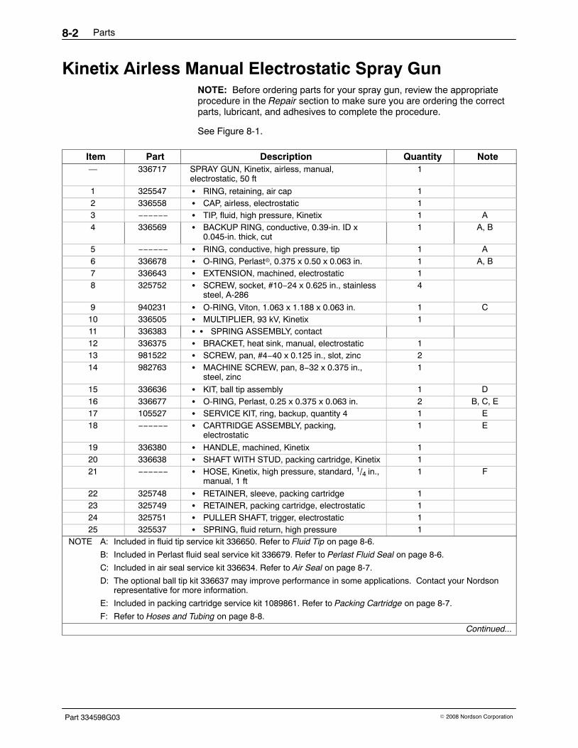
Parts8-2
Part 334598G03 � 2008 Nordson Corporation
Kinetix Airless Manual Electrostatic Spray Gun NOTE: Before ordering parts for your spray gun, review the appropriateprocedure in the Repair section to make sure you are ordering the correctparts, lubricant, and adhesives to complete the procedure.
See Figure 8-1.
Item Part Description Quantity Note— 336717 SPRAY GUN, Kinetix, airless, manual,
electrostatic, 50 ft1
1 325547 � RING, retaining, air cap 12 336558 � CAP, airless, electrostatic 13 −−−−−− � TIP, fluid, high pressure, Kinetix 1 A4 336569 � BACKUP RING, conductive, 0.39-in. ID x
0.045-in. thick, cut1 A, B
5 −−−−−− � RING, conductive, high pressure, tip 1 A6 336678 � O-RING, Perlast�, 0.375 x 0.50 x 0.063 in. 1 A, B7 336643 � EXTENSION, machined, electrostatic 18 325752 � SCREW, socket, #10−24 x 0.625 in., stainless
steel, A-2864
9 940231 � O-RING, Viton, 1.063 x 1.188 x 0.063 in. 1 C10 336505 � MULTIPLIER, 93 kV, Kinetix 111 336383 � � SPRING ASSEMBLY, contact12 336375 � BRACKET, heat sink, manual, electrostatic 113 981522 � SCREW, pan, #4−40 x 0.125 in., slot, zinc 214 982763 � MACHINE SCREW, pan, 8−32 x 0.375 in.,
steel, zinc1
15 336636 � KIT, ball tip assembly 1 D16 336677 � O-RING, Perlast, 0.25 x 0.375 x 0.063 in. 2 B, C, E17 105527 � SERVICE KIT, ring, backup, quantity 4 1 E18 −−−−−− � CARTRIDGE ASSEMBLY, packing,
electrostatic1 E
19 336380 � HANDLE, machined, Kinetix 120 336638 � SHAFT WITH STUD, packing cartridge, Kinetix 121 −−−−−− � HOSE, Kinetix, high pressure, standard, 1/4 in.,
manual, 1 ft1 F
22 325748 � RETAINER, sleeve, packing cartridge 123 325749 � RETAINER, packing cartridge, electrostatic 124 325751 � PULLER SHAFT, trigger, electrostatic 125 325537 � SPRING, fluid return, high pressure 1
NOTE A: Included in fluid tip service kit 336650. Refer to Fluid Tip on page 8-6.
B: Included in Perlast fluid seal service kit 336679. Refer to Perlast Fluid Seal on page 8-6.
C: Included in air seal service kit 336634. Refer to Air Seal on page 8-7.
D: The optional ball tip kit 336637 may improve performance in some applications. Contact your Nordsonrepresentative for more information.
E: Included in packing cartridge service kit 1089861. Refer to Packing Cartridge on page 8-7.
F: Refer to Hoses and Tubing on page 8-8.
Continued...

Parts 8-3
Part 334598G03� 2008 Nordson Corporation
35
1
78
10
1716
15
20
2223
24
25
38
16
21
28
29
27
26
19
30
31
32
34
38
40
4849
5051
36
41
4243
45
1812
13
14
3938
37
2
33 4746
9
53
3
46
5
11
44
52
Figure 8-1 Kinetix Airless Manual Electrostatic Spray Gun
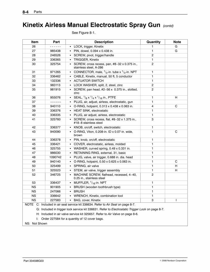
Parts8-4
Part 334598G03 � 2008 Nordson Corporation
Kinetix Airless Manual Electrostatic Spray Gun (contd)
See Figure 8-1.
Item Part Description Quantity Note26 - - - - - - � LOCK, trigger, Kinetix 1 G27 985438 � PIN, dowel, 0.094 x 0.438 in. 1 G28 246526 � SCREW, pivot, trigger/handle 229 336365 � TRIGGER, Kinetix 130 325754 � SCREW, cross recess, pan, #8−32 x 0.375 in.,
stainless steel, A-2862
31 971265 � CONNECTOR, male, 1/4-in. tube x 1/4-in. NPT 132 336462 � CABLE, Kinetix, manual, 50 ft, 5 conductor 133 132336 � ACTUATOR SWITCH 134 983113 � LOCK WASHER, split, 2, steel, zinc 235 981915 � SCREW, pan head, #2−56 x 0.375 in., slotted,
zinc2
36 955076 � SEAL, 1/8 x 1/4 x 1/16 in., PTFE 1 H37 −−−−−− � PLUG, air, adjust, airless, electrostatic, gun 138 940110 � O-RING, hotpaint, 0.313 x 0.438 x 0.063 in. 4 C39 336376 � HEAT SINK, electrostatic 140 336335 � PLUG, air adjust, airless, electrostatic 141 325760 � SCREW, cross recess, flat, #8−32 x 1.375 in.,
#18−8 stainless steel3
42 336377 � KNOB, on/off, switch, electrostatic 143 940090 � O-RING, Viton, 0.208-in. ID x 0.07-in. wide,
brown1 C
44 336378 � PIN, knob, on/off, electrostatic 145 336421 � COVER, electrostatic, airless, molded 146 325755 � WASHER, curved spring, 0.49 x 0.331 in. 147 986030 � RETAINING RING, external, 31, basic 148 1090742 � PLUG, valve, air trigger, 0.688 in. dia. head 149 940140 � O-RING, hotpaint, 0.50 x 0.625 x 0.063 in. 1 C50 325499 � SPRING, air valve 1 H51 325523 � STEM, air valve, trigger assembly 1 H52 346725 � MACHINE SCREW, flathead, recessed, 4−40,
0.25 in., stainless steel2
53 336437 � MUFFLER, 1/16-in. NPT 1NS 901905 � BRUSH (wooden toothbrush type) 1NS 247066 � BRUSH 1NS 336642 � WRENCH, Kinetix, combination tool 1NS 227583 � BAG, cover, Kinetix 3 I
NOTE C: Included in air seal service kit 336634. Refer to Air Seal on page 8-7.
G: Included in trigger lock service kit 336631. Refer to Electrostatic Trigger Lock on page 8-7.
H: Included in air valve service kit 325657. Refer to Air Valve on page 8-6.
I: Order 227584 for a quantity of 12 cover bags.
NS: Not Shown

Parts 8-5
Part 334598G03� 2008 Nordson Corporation
35
1
78
10
1716
15
20
2223
24
25
38
16
21
28
29
27
26
19
30
31
32
34
38
40
4849
5051
36
41
4243
45
1812
13
14
3938
37
2
33 4746
9
53
3
46
5
11
44
52
Figure 8-1 Kinetix Airless Manual Electrostatic Spray Gun

Parts8-6
Part 334598G03 � 2008 Nordson Corporation
Adhesives, Sealants, and LubricantsUse these adhesives, sealants, and lubricants when repairing your unit.Refer to the Repair section in this manual for application instructions.
Part Description Quantity900464 ADHESIVE, threadlocking (Loctite Removable 242) 1900349 PTFE-FILLED LUBRICANT, O-ring, (MagnaLube) , 0.75-oz tube 1900481 ADHESIVE, pipe/thread/hydraulic sealant 1247658 DIELECTRIC GREASE APPLICATOR, 10 cc, 12 count 1
Recommended KitsSee Figure 8-1.
Perlast Fluid Seal
Item Part Description Quantity Note— 336679 FLUID SEAL KIT, Perlast, gun, Kinetix 14 336569 � BACKUP RING, conductive, 0.39-in. ID x
0.045-in. thick, cut1 A
6 336678 � O-RING, Perlast, 0.375 x 0.50 x 0.063 in. 1 A16 336677 � O-RING, Perlast, 0.25 x 0.375 x 0.063 in. 2 B
NOTE A: Used on the fluid tips.
B: Used on the packing cartridge and fluid hose.
Fluid Tip
Item Part Description Quantity Note— 336560 FLUID TIP, high pressure, Kinetix 13 −−−−−− � TIP, fluid, high pressure, electrostatic 14 336569 � BACKUP RING, conductive, 0.39-in. ID x
0.045-in. thick, cut1
5 −−−−−− � RING, conductive, 0.39-in. ID x 0.045 in. thick,cut
1
6 336678 � O-RING, Perlast, 0.375 x 0.50 x 0.063 in. 1
Air Valve
Item Part Description Quantity Note— 325657 AIR VALVE KIT 136 955076 � SEAL, 1/8 x 1/4 x 1/16 in., PTFE 150 325499 � SPRING, air valve 151 325523 � STEM, air valve, trigger assembly 1

Parts 8-7
Part 334598G03� 2008 Nordson Corporation
Air Seal
Item Part Description Quantity Note— 336634 Kit, air seal, hotpaint, electrostatic 19 940231 � O-RING, Viton, 1.063 x 1.188 x 0.063 in. 138 940110 � O-RING, hotpaint, 0.313 x 0.438 x 0.063 in. 443 940090 � O-RING, Viton, 0.208-in. ID x 0.07-in. wide,
brown1
49 940140 � O-RING, hotpaint, 0.50 x 0.625 x 0.063 in. 1NS 940130 � O-RING, hotpaint, 0.438 x 0.563 x 0.063 in. 1 ANS 336512 � O-RING, PTFE, 0.313 x 0.438 x 0.063 in.,
special1 A
NOTE A: This O-ring is not used with this spray gun.NS: Not Shown
Packing CartridgeNOTE: The Kinetix spray gun is shipped with the gold packing cartridge,which is appropriate for most coating materials. Use the optional PTFEpacking cartridge 1089862 with harsh chemical solvents such as MEK.
Item Part Description Quantity Note— 1089861 PACKING CARTRIDGE KIT, gold, Kinetix 116 336677 � O-RING, Perlast, 0.25 x 0.375 x 0.063 in. 117 −−−−−− � BACKUP RING, single, 1/4 x 3/8 in. 118 −−−−−− � CARTRIDGE ASSEMBLY, packing 1
Trigger Lock
Item Part Description Quantity Note— 336631 TRIGGER LOCK KIT, electrostatic 126 −−−−−− � LOCK, trigger, Kinetix 127 985438 � PIN, dowel, 0.094 x 0.438 in., alloy steel,
hardened and ground1

Parts8-8
Part 334598G03 � 2008 Nordson Corporation
Optional Hotpaint Fluid Seal The standard fluid seal O-rings for all Kinetix products provide solventresistance. If a particular application does not require solvent resistancethen the hotpaint seal kit can be used instead. These O-rings should not beused with highly polar solvents like Acetone and MEK, ChlorinatedHydrocarbons and Nitro Hydrocarbons unless they will be replacedregularly.
Part Description Quantity Note336633 HOTPAINT FLUID SEAL KIT, electrostatic 1336569 � BACKUP RING, conductive, 0.39-in. ID x 0.045-in. thick, cut 1 A940120 � O-RING, hotpaint, 0.375 x 0.50 x 0.063 in. 1 A940100 � O-RING, hotpaint, 0.25 x 0.375 x 0.063 in. 2 B
NOTE A: Used on the fluid tips.
B: Used on the packing cartridge and fluid hose.
Optional PTFE Packing Cartridge NOTE: The PTFE packing cartridge is available for use with harsh chemicalsolvents such as MEK.
Part Description Note1089862 KIT, cartridge, packing, Kinetix, electrostatic, PTFE−−−−−− � CARTRIDGE ASSEMBLY, packing, electrostatic−−−−−− � BACKUP RING, single, 1/4 x 3/8 in.336677 � O-RING, Perlast, 0.25 x 0.375 x 0.063 in.
Hoses and TubingHoses and tubing are optional and must be ordered separately.
Part Description Quantity Note336337 HOSE KIT, Kinetix, high pressure, standard, manual, electrostatic,
1-ft length, 0.25-in. ID1 A
900509 TUBING, air, polyethylene, 0.25-in. OD x 0.04-in. wall AR B900556 TUBING, air, nylon, 0.25-in. OD x 0.035-in. wall AR B
NOTE A: Any high-pressure hose can be added to this hose to increase the length. Refer to the High-PressureFluid Hoses instruction sheet for ordering information.
B: Order tubing in one-foot increments.
AR: As Required
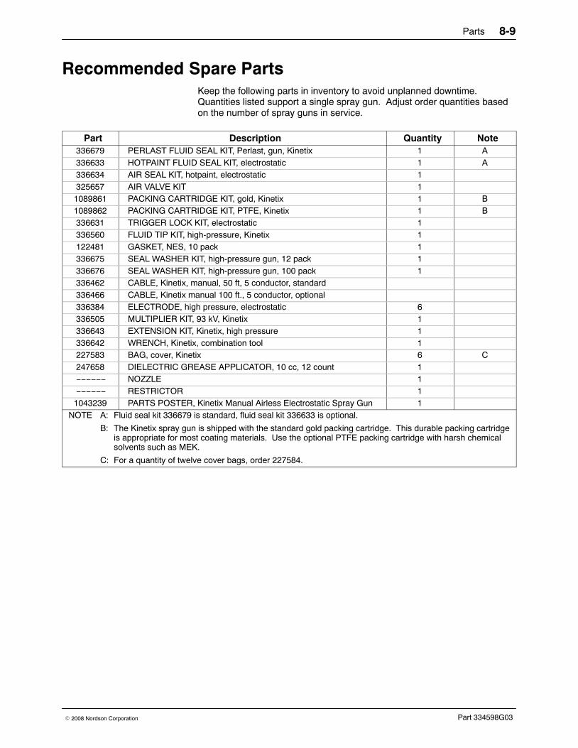
Parts 8-9
Part 334598G03� 2008 Nordson Corporation
Recommended Spare PartsKeep the following parts in inventory to avoid unplanned downtime.Quantities listed support a single spray gun. Adjust order quantities basedon the number of spray guns in service.
Part Description Quantity Note336679 PERLAST FLUID SEAL KIT, Perlast, gun, Kinetix 1 A336633 HOTPAINT FLUID SEAL KIT, electrostatic 1 A336634 AIR SEAL KIT, hotpaint, electrostatic 1325657 AIR VALVE KIT 11089861 PACKING CARTRIDGE KIT, gold, Kinetix 1 B1089862 PACKING CARTRIDGE KIT, PTFE, Kinetix 1 B336631 TRIGGER LOCK KIT, electrostatic 1336560 FLUID TIP KIT, high-pressure, Kinetix 1122481 GASKET, NES, 10 pack 1336675 SEAL WASHER KIT, high-pressure gun, 12 pack 1336676 SEAL WASHER KIT, high-pressure gun, 100 pack 1336462 CABLE, Kinetix, manual, 50 ft, 5 conductor, standard336466 CABLE, Kinetix manual 100 ft., 5 conductor, optional336384 ELECTRODE, high pressure, electrostatic 6336505 MULTIPLIER KIT, 93 kV, Kinetix 1336643 EXTENSION KIT, Kinetix, high pressure 1336642 WRENCH, Kinetix, combination tool 1227583 BAG, cover, Kinetix 6 C247658 DIELECTRIC GREASE APPLICATOR, 10 cc, 12 count 1−−−−−− NOZZLE 1−−−−−− RESTRICTOR 11043239 PARTS POSTER, Kinetix Manual Airless Electrostatic Spray Gun 1
NOTE A: Fluid seal kit 336679 is standard, fluid seal kit 336633 is optional.
B: The Kinetix spray gun is shipped with the standard gold packing cartridge. This durable packing cartridgeis appropriate for most coating materials. Use the optional PTFE packing cartridge with harsh chemicalsolvents such as MEK.
C: For a quantity of twelve cover bags, order 227584.

Parts8-10
Part 334598G03 � 2008 Nordson Corporation
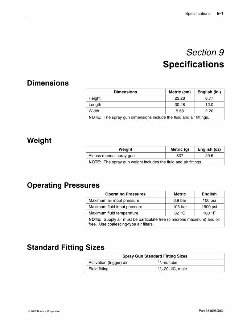
Specifications 9-1
Part 334598G03� 2008 Nordson Corporation
Section 9Specifications
DimensionsDimensions Metric (cm) English (in.)
Height 22.28 8.77
Length 30.48 12.0
Width 5.58 2.20
NOTE: The spray gun dimensions include the fluid and air fittings.
WeightWeight Metric (g) English (oz)
Airless manual spray gun 837 29.5
NOTE: The spray gun weight includes the fluid and air fittings.
Operating PressuresOperating Pressures Metric English
Maximum air input pressure 6.9 bar 100 psi
Maximum fluid input pressure 103 bar 1500 psi
Maximum fluid temperature 82 �C 180 �F
NOTE: Supply air must be particulate free (5 microns maximum) and oilfree. Use coalescing-type air filters.
Standard Fitting SizesSpray Gun Standard Fitting Sizes
Activation (trigger) air 1/4-in. tube
Fluid fitting 1/2-20 JIC, male

Specifications9-2
Part 334598G03 � 2008 Nordson Corporation
Gun ElectrostaticsMaximum voltage: 93 kV
Maximum output rating current: 122 microamps
NOTE: Current draw greater than 50 A may affect spray pattern, transferefficiency and finish. If the conductivity of your material causes excessivecurrent draw, changing to the longer hose may be necessary.
Conductivity RangeFor optimum electrostatics coating resistivity the conductivity range shouldbe greater than 25 megohms/cm.
ApprovalsThis spray gun has met the requirements for CE and FM approval.
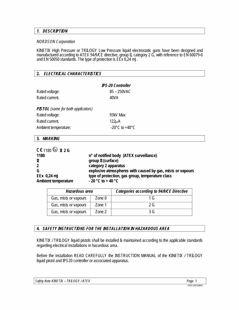
Safety Note KINETIX – TRILOGY / ATEX Page 1 DOC13015B05
1. DESCRIPTION NORDSON Corporation KINETIX High Pressure or TRILOGY Low Pressure liquid electrostatic guns have been designed and manufactured according to ATEX 94/9/CE directive, group II, category 2 G, with reference to EN 60079-0 and EN 50050 standards. The type of protection is EEx 0,24 mJ.
2. ELECTRICAL CHARACTERISTICS
IPS-20 Controller Rated voltage: 85 – 250VAC Rated current. 40VA
PISTOL (same for both applicators) Rated voltage: 93kV Max
Rated current. 122A Ambient temperature: -20°C to +40°C
3. MARKING
1180 II 2 G 1180 n° of notified body (ATEX surveillance) II group II (surface) 2 category 2 apparatus G explosive atmospheres with caused by gas, mists or vapours EEx 0,24 mJ type of protection, gas group, temperature class Ambient temperature - 20 °C to + 40 °C
Hazardous area Categories according to 94/9/CE Directive
Gas, mists or vapours Zone 0 1 G
Gas, mists or vapours Zone 1 2 G
Gas, mists or vapours Zone 2 3 G
4. SAFETY INSTRUCTIONS FOR THE INSTALLATION IN HAZARDOUS AREA
KINETIX / TRILOGY liquid pistols shall be installed & maintained according to the applicable standards regarding electrical installations in hazardous area. Before the installation READ CAREFULLY the INSTRUCTION MANUAL of the KINETIX / TRILOGY liquid pistol and IPS20 controller or associated apparatus.

Safety Note KINETIX – TRILOGY / ATEX Page. 2 DOC13015B05
5. EXAMPLE OF APPLICATION This shows the applicators and how a typical system is configured.

Safety Note KINETIX – TRILOGY / ATEX Page. 3 DOC13015B05
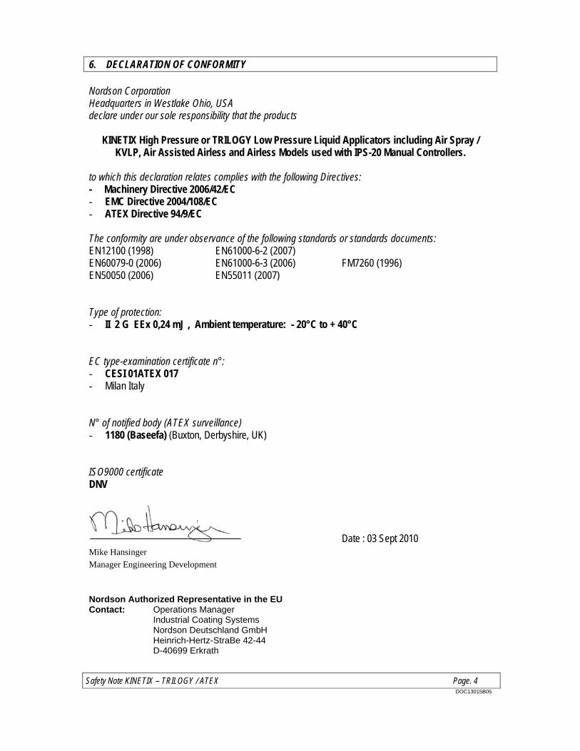
Safety Note KINETIX – TRILOGY / ATEX Page. 4 DOC13015B05
6. DECLARATION OF CONFORMITY Nordson Corporation Headquarters in Westlake Ohio, USA declare under our sole responsibility that the products
KINETIX High Pressure or TRILOGY Low Pressure Liquid Applicators including Air Spray / KVLP, Air Assisted Airless and Airless Models used with IPS-20 Manual Controllers.
to which this declaration relates complies with the following Directives: - Machinery Directive 2006/42/EC - EMC Directive 2004/108/EC - ATEX Directive 94/9/EC The conformity are under observance of the following standards or standards documents: EN12100 (1998) EN61000-6-2 (2007) EN60079-0 (2006) EN61000-6-3 (2006) FM7260 (1996) EN50050 (2006) EN55011 (2007) Type of protection: - II 2 G EEx 0,24 mJ , Ambient temperature: - 20°C to + 40°C EC type-examination certificate n°: - CESI 01ATEX 017 - Milan Italy N° of notified body (ATEX surveillance) - 1180 (Baseefa) (Buxton, Derbyshire, UK) ISO9000 certificate DNV
Date : 03 Sept 2010 Mike Hansinger Manager Engineering Development
Nordson Authorized Representative in the EU Contact: Operations Manager Industrial Coating Systems Nordson Deutschland GmbH Heinrich-Hertz-StraBe 42-44 D-40699 Erkrath