Embed Size (px)
Citation preview

8/14/2019 Kinetic Energy Supported Electrically Powered Transportation Structures
http://slidepdf.com/reader/full/kinetic-energy-supported-electrically-powered-transportation-structures 1/12
KINETIC ENERGY SUPPORTED ELECTRICALLY POWERED
TRANSPORTATION STRUCTURESJames E. D. Cline
Independent Researcher 9800-D Topanga Cyn Blvd #118, Chatsworth, CA 91311
E-mail: [email protected] http://home.earthlink.net/~jedcline/
Abstract
Similar to the dynamic braking of an electricmotor/generator, which connects the kinetic energy of the rotating armature into a torque force drag againstthe stationary stator part of the motor/generator, theelectromagnetic drag of a rapidly rising series of armature sections drags upward on the stationary partof a very tall structure to exactly balance the weight of the stationary structure, the lift force distributed alongthe structure. With appropriately fast rising mass andelectromagnetic coupling balancing the distributedweight, earth surface to space transportation structuresbecome conceivable. The fast rising armature massstream also distributes electromagnetic lift drag energycoupling to vehicles rising up that structure to space.
Stabilized by laterally-coupling mass stream pairs andby active position feedback servo systems, these would
___________________________ Copyright © 1997 by James Edward David Cline. Presented to, butnot published by the Space Studies Institute, Inc.
be dynamic transportation bridging structures. SeedKESTS would be launched and flown up and around
the planet back to the starting point, then bootstrappedup to full working size. Such electrically powered railbridging transportation structures from Earth surface toGEO could conceivably provide the massivetransportation capacity to build a new civilizationencircling the Earth in the Clark Belt geosynchronousorbit, a long term project hopefully to unite humanitytoward common cooperative venture goals.
A Brief Description of the KESTS Concept
Kinetic energy can stiffen and strengthenstructures. Analogous examples include balloons and
pressurized fuel tanks that are strengthened by thekinetic energy of the internal pressurized gas’s
8/14/2019 Kinetic Energy Supported Electrically Powered Transportation Structures
http://slidepdf.com/reader/full/kinetic-energy-supported-electrically-powered-transportation-structures 2/12
omnidirectional kinetic energy; and a jet of highpressure liquid creates an arch shaped structure inagravitational field. The arch formed by that highpressure mass stream jet of liquid could support theweight of a lightweight sheath around it, a sheathunmoving relative to the ground, forming a kind of bridge supported by kinetic energy.
Now consider an electromechanical analog of that high pressure jet of liquid. Recall that electricalenergy is converted to kinetic energy by electricalmotors, rotary and linear. Motors can be designed todo the reverse, too, becoming an electrical generatordriven by kinetic energy. And torque or thrust is alsocoupled between the relatively moving parts of amotor/generator.
Imagine an electric rotary motor/generatorwhose armature (rotor), instead of spinning around acentral shaft, slides around inside the stator on amaglev (magnetic levitation) track. And imagine thatarmature being in sections, not physically directly
connected to each other, like many trains riding thesame maglev tracks, in a circle.
Stretch out the motor/generator so big that itcircles the Earth, using the gravitational field to pull itaround in a closed loop which contacts the earthsurfaceon one part and then reaches out to GEO far above theopposite side of the planet as it goes around. Have thearmature sections travel on the maglev tracks insideevacuated tubing at above orbital velocity. Let thedynamic drag of the upward-bound armature sectionsprovide a lift force on the track-stator-tubing exactlythat amount required to support the distributed weightof the tubing, making the tubing earthsurface-
stationary. This acts to compress the trajectory of themass stream toward the Earth. Thus the tensile strengthof the tubing need only be enough to cope with thestatic and live loads between drag lift mechanismpoints along the tubing. As the creation of this lift forceextracts some of the kinetic energy from the armaturemass stream, each armature section’s position andvelocity is re-initialized at the earthsurface contactsite, initially drawing the energy needed to do this fromthe earthsurface electrical power grid.
Continuing with this envisioning, put maglevtracks also on the outside of the tubing, for payload-carrying vehicles to use. Enable those vehicles also to
drag electromagnetically on the high velocity risingmass stream of armature sections, lifting the vehiclesup the structure from earthsurface to space, up to theGEO Clarke Belt orbital altitude. Call thistransportation structure a “KESTS”, short for KineticEnergy Supported Electrically Powered TransportationStructures. Use the KESTS to lift constructionmaterials up to GEO for building the first few large-scale space habitats, such as mile-diameter wheel-likehabitats with 1-g STP interiors for 10,000 people each,including agriculture and light industry. Build more of these large space habitats, mostly made of lunar and
asteroidal-sourced materials, loosely coupling themtogether to infill the Clarke Belt with them. Eachcomplete ring of them is home for 15 billion people.Build enough KESTS to lift 1,000,000 people a day tothe Clarke Belt Orbital Habitat Ring, along with theirhousehold belongings. Make the Orbital Habitat Ring(OHR) sufficiently safe and luxurious to entice themajority of the earthsurface population to move up the
KESTS to live in it, creating a new primary site forhuman civilization. Restore the earthsurface ecosystemto natural balance. Expand human civilization outwardfrom the Earth’s OHR. This is an outline of a KESTSto OHR (Kinetic Energy Supported ElectricallyPowered Transportation Structure to an OrbitingHabitat Ring) project.1
Purpose
Building transportation structures, a form of elevator-bridges, to connect the ground all the way upto orbital altitudes may seem absurd; however, such
structures are being considered here. The intent is tocreate a transportation system adequate to the task of lifting the majority of the Earth’s population up intospace, lifting perhaps 7 billion people and theirhousehold goods over a 20 year time span, to live in aring of loosely coupled large scale 1-g STP interiorhabitats encircling the Earth in the geosynchronousClarke Belt orbit. This is hoped will enable a near-future vigorous expansion of earthlife into space,expanding human civilization far beyond that possiblein a closed ecosystem, and restoration of the Earth’ssurface ecosystem to a healthy long term balance as aprecious biological resource for the future. Anelectrically powered bridging rail transportation
structure spanning between the earth surface andGeosynchronous Earth Orbit seems most likely to havethe capacity to be able to do that task.
Background
Historically, the urge to climb high to a safehaven may reach as far back as the trees; in the dawnof civilization, the Tower of Babel at E-Temen-An-Kihad the goal of building a tower from ground to theheavens; in 1960 Artsutanov proposed ageosynchronous centrifugally supported tether type of tower structure for supporting an electric elevator intospace; in 1982 Keith Lofstrom proposed a kineticallyaugmented structure called a Launch Loop which was acontinuous belt loosely driven between two pulleys,the centrifugal force of the loose belt flinging it to thefringes of the atmosphere in its journey around thepulleys; in 1985 Rod Hyde proposed a vertical towerenclosing a fountain of electromagnetically coupledberyllium disks, which he calculated could lift thecombined weight of every human being on the planetup to the fringes of the atmosphere while using onlythe electrical energy used by the City of Los Angeles ina mere two weeks; and also in 1985 Earle Smith

8/14/2019 Kinetic Energy Supported Electrically Powered Transportation Structures
http://slidepdf.com/reader/full/kinetic-energy-supported-electrically-powered-transportation-structures 3/12
proposed a continuous belt eccentrically reachingaround the planet, contacting the planetary surface onthe equator and reaching geosynchronous earth orbit atits high point above the far side of the planet.2,3,4,5,6
Quickly moving the primary site of humancivilization off-planet has been considered essentiallyan impossible option up until now. But at the present
time, human civilization piles up unrecyclable toxicrefuse, entropically dispersing metallic ore depositsbeyond reconcentration, burns the oxygen producingrainforests along with their genetic treasures, and burnsfossil fuels a million times faster than a forestedecosystem could replace it. In terms of population size,we long ago passed the limits for long term sustainablelevels for living in harmony with the naturalecosystem, even given a fully aware and responsiblehumanity of only 10% of the present population.
KESTS as a Key to an Overall Solution
People prefer to live in man-made structures,and space habitats are about as man-made as you canget. So let us consider creating a transportation systemadequate to move some 7 billion people over a periodof 20 years out to the Clarke Belt, along with theirhousehold belongings, plants and pets, along with allthe agricultural, industrial, and markets civilizationneeds for a solid resettlement there. For now, let us justcreate the option; later humanity can choose to utilize itor not. KESTS may be able to shoulder that task, alongwith lifting the construction materials for the first fewsuch 10,000-person space habitats, solar electric powerstations, and construction materials for a head start inbuilding an asteroidal and lunar mining and materials
processing base to provide structural materials for mostof the vast ring of space habitats to orbit the Earth, asite for a great civilization and way station to the solarsystem’s resources there awaiting to be brought to life.
Basic KESTS Technology
The compressive strength of known materialsis very inadequate to the task of bearing the weight of such immense structures, so the compressive loadwould largely be carried by compression of thetrajectory of mass streams circulating within thestructure at above orbital velocities, the distributedweight of the fixed structure supported byelectromagnetic drag against the rapidly risingarmature mass streams. The mass stream armaturesections’ velocity are referenced to the Earth surface,so the load of the weight of the structure, and payloadmoving in vehicles upon it, is transferred by the massstreams to the ground load bearing. The pulsingelectromagnetic energy of magnets contained withinthe armature mass stream is inductively coupled to thedistributed load of the structure, and to the vehiclestraveling upon the structure. Similarly, energy is put
into the structure by electromagnetic coupling to themass stream at the earthsurface contact sites.7
To support the enormous weight of such earthsurface to space bridging structures, electrodynamiccoupling of equally enormous upward bound armaturemass streams traveling within them circulating at fasterthan orbital velocity, drag electromagnetically upward
on the earthsurface-stationary part of the structures,slowing the upward bound mass stream slightly inreturn for support of that weight, compressing thetrajectories slightly toward the Earth. This distributesthe energy required to provide the upward force thatopposes the force of gravity on the earth-stationary partof the transportation structure, electromagneticallydragging against the structure as it rises, just enough tobalance the weight of the structure everywhere alongits length, and supplying a small position bias tension.
KESTS Analogy to an Electric Motor/Generator
The structure thus resembles an electric motor/ generator in an electrodynamic braking mode, the massof the “motionless” stator being torqued by theelectromagnetically coupled drag force from thearmature rotor whizzing past the stator, positioned suchthat the torque provides an upward-oriented forceopposing the force of gravity. In this view the“armature” is the mass stream. and the “stator” is theearthsurface-stationary part of the structure.
The Mass Stream Armature Sections
The mass stream is composed of armaturesections performing several functions. Their primaryfunction is to provide the storage and exchange of thekinetic energy which supports the compression load of the structure’s weight, and distributes energy to movepayload along the structures. Some modified armaturesections may also function directly as vehiclestransporting payload within the mass stream itself, andother forms of armature sections may be the payloaditself on a one-way trip up or down as raw material.Armature sections need to be designed to resist contactwith each other somehow avoiding such contact wear;

8/14/2019 Kinetic Energy Supported Electrically Powered Transportation Structures
http://slidepdf.com/reader/full/kinetic-energy-supported-electrically-powered-transportation-structures 4/12
so perhaps they will need periodic automatic inspectionand repair/replacement. Armature sections exchangeenergy within the KESTS by rising/falling in agravitational field, and electrically through permanentand induced magnetism, and electrostatically. Theelectric field energy exchanges support the structure,center the mass stream within the tubing, input andextract energy to the mass stream, sense armaturesection position and velocity, for re-initializationprocesses, and prevent physical abrasive contact.
KESTS Analogy to a Lasso
To picture how this structure fits into thegravitational space around the Earth, let’s mentallypicture a cowboy's lasso, a circle of rope spinningabove his head, as in the following drawing. Itssemicircular shape is held by energy stored in the lasso,by the centrifugal force distributed outward from therope loop's center of rotation.
Now mentally extend that fast-spinning rope soas to encircle the earth, grazing the surface of theplanet and also reaching far out into space on the otherside of the planet. Then sheath the lasso in tubing to
exclude air from the path in which it directly moves,supporting the weight of the tubing by compressing itsmoothly along the radius of rotation of the spinninglasso, whose centrifugal force would press back outward against the sheath. Attach this tubing to theearth surface where the lasso grazes the planetarysurface: the tubing now is effectively a structureextending from the ground out into space. Tappingsome of the nearby speedy lasso's kinetic energy,vehicles can lift up along the structure from the groundinto space, carrying no propulsion fuel aboard them,like tram cars lifted into space.
The lasso rope is equivalent to the rotor in themotor analogy (which is turn is analogous to the highvelocity armature mass stream), and the rim isequivalent to its stator (which in turn is analogous tothe earthsurface-stationary part of the structure). Wherethe lasso/rotor is upward bound in the gravitationalfield, it provides a lift force on the rim/stator. Laterally-coupled counterrotating pairs of these structures
provide upward-bound lasso/rotor (mass stream)kinetic energy to provide lift force to the rim/stator(earthsurface-stationary part of structure) all along itslength.
Each of the armature mass streams effectivelytravel on maglev tracks inside tubing which forms theearthsurface-stationary part of the KESTS structure,the rim/stator part of the structure in the above analogy.On the outside of this earthsurface-stationary tubing,payload-carrying vehicles travel along other maglevtracks. They, too, electrodynamically brake against therising mass stream as they lift up from the surface of the Earth to the earth geosynchronous orbital altitude,
extracting energy from the rising mass stream toprovide lift force for the vehicles; this energy isintrinsically distributed all along the transportationstructure. Eliminating need for electricalsuperconductors all along the structure for transferringelectrical power to raise vehicles along the structure,the high velocity mass streams provide the energy tothe point of need everywhere along the structure, bothto support the structure against the force of gravity andto provide lift energy to vehicles riding up to spacealong the structure.8
8/14/2019 Kinetic Energy Supported Electrically Powered Transportation Structures
http://slidepdf.com/reader/full/kinetic-energy-supported-electrically-powered-transportation-structures 5/12
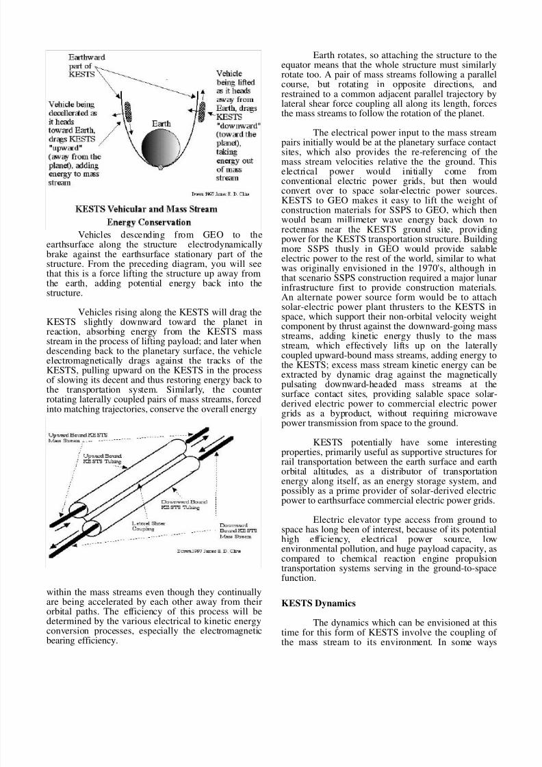
Vehicles descending from GEO to theearthsurface along the structure electrodynamicallybrake against the earthsurface stationary part of the
structure. From the preceding diagram, you will seethat this is a force lifting the structure up away fromthe earth, adding potential energy back into thestructure.
Vehicles rising along the KESTS will drag theKESTS slightly downward toward the planet inreaction, absorbing energy from the KESTS massstream in the process of lifting payload; and later whendescending back to the planetary surface, the vehicleelectromagnetically drags against the tracks of theKESTS, pulling upward on the KESTS in the processof slowing its decent and thus restoring energy back tothe transportation system. Similarly, the counter
rotating laterally coupled pairs of mass streams, forcedinto matching trajectories, conserve the overall energy
within the mass streams even though they continuallyare being accelerated by each other away from theirorbital paths. The efficiency of this process will bedetermined by the various electrical to kinetic energyconversion processes, especially the electromagneticbearing efficiency.
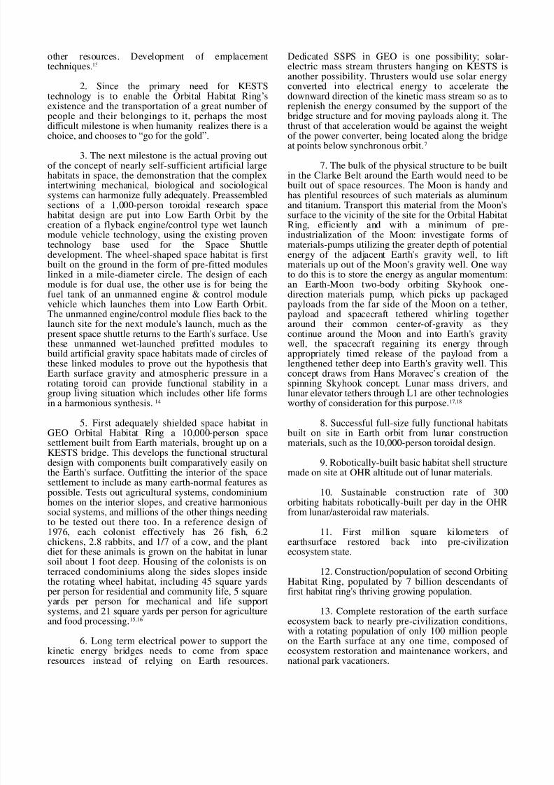
Earth rotates, so attaching the structure to theequator means that the whole structure must similarlyrotate too. A pair of mass streams following a parallelcourse, but rotating in opposite directions, andrestrained to a common adjacent parallel trajectory bylateral shear force coupling all along its length, forcesthe mass streams to follow the rotation of the planet.
The electrical power input to the mass streampairs initially would be at the planetary surface contactsites, which also provides the re-referencing of themass stream velocities relative the the ground. Thiselectrical power would initially come fromconventional electric power grids, but then wouldconvert over to space solar-electric power sources.KESTS to GEO makes it easy to lift the weight of construction materials for SSPS to GEO, which thenwould beam millimeter wave energy back down torectennas near the KESTS ground site, providingpower for the KESTS transportation structure. Buildingmore SSPS thusly in GEO would provide salableelectric power to the rest of the world, similar to what
was originally envisioned in the 1970's, although inthat scenario SSPS construction required a major lunarinfrastructure first to provide construction materials.An alternate power source form would be to attachsolar-electric power plant thrusters to the KESTS inspace, which support their non-orbital velocity weightcomponent by thrust against the downward-going massstreams, adding kinetic energy thusly to the massstream, which effectively lifts up on the laterallycoupled upward-bound mass streams, adding energy tothe KESTS; excess mass stream kinetic energy can beextracted by dynamic drag against the magneticallypulsating downward-headed mass streams at thesurface contact sites, providing salable space solar-
derived electric power to commercial electric powergrids as a byproduct, without requiring microwavepower transmission from space to the ground.
KESTS potentially have some interestingproperties, primarily useful as supportive structures forrail transportation between the earth surface and earthorbital altitudes, as a distributor of transportationenergy along itself, as an energy storage system, andpossibly as a prime provider of solar-derived electricpower to earthsurface commercial electric power grids.
Electric elevator type access from ground tospace has long been of interest, because of its potential
high efficiency, electrical power source, lowenvironmental pollution, and huge payload capacity, ascompared to chemical reaction engine propulsiontransportation systems serving in the ground-to-spacefunction.
KESTS Dynamics
The dynamics which can be envisioned at thistime for this form of KESTS involve the coupling of the mass stream to its environment. In some ways

8/14/2019 Kinetic Energy Supported Electrically Powered Transportation Structures
http://slidepdf.com/reader/full/kinetic-energy-supported-electrically-powered-transportation-structures 6/12
resembling the spinning rotor of an electric motor, themass of this armature is going around faster than theorbital velocity at any altitude, held lower by theweight of the sustained loads of passive structure andits live loads. The armature mass stream couples to itsenvironment through electrical fields. Pushing from theearthsurface contact anchor re-initialization site, themass stream is re-accelerated and repositioned to
restore energy consumed along the KESTS pathway,compensating for live loads and lateral forces on theKESTS. From this re-initialization site, the massstream heads back upward, electromagneticallydragging weakly against the passive structure aroundits path, as well as dragging against coupling tovehicles tapping that energy to lift them up the KESTS.The passive structure involves the evacuated tubing inwhich it flows, the shear coupling between counterrotating stream tubes, and the guidance tracks for liveloads such as passenger vehicles. Note that live loadsbeing lifted along the KESTS exert a downward forceon the structure's mass stream, but live loads which aredecelerating back toward the earth surface exert an
upward force on the tracks thus adding energy back into the transportation system.
Non-uniform electromagnetic fields couplekinetic energy between a circulating loop of highvelocity mass, which appear as pulsating magneticfields to stationary parts of the mass stream'senvironment, inducing alternating currents and definingthe phasing for inputting electrical power into the massstream. The mass stream whirling around a planetarybody in an eccentric path, which contacts the surface atits low point, is squeezed toward the planet by theweight of portions of the structure which are stationaryrelative to the planet.
Each mass stream is contained within thetubing in which it flows, tubing which excludes theatmosphere where near the earth, supports vehiculartracks, defines the path of the mass streams, andprovides structure for the lateral shear couplingbetween counter rotating mass streams. Payload iscarried primarily in vehicles on low-friction maglevtracks, and the vehicles electromagnetically drag on the
upward-bound mass stream when rising up the KESTS.
KESTS to GEO, otherwise known as theClarke Belt, would have the advantage of requiringminimum difficulty embarking and disembarking ateither terminal due to velocities being intrinsicallymatched at both ends, potentially a walk-on atearthsurface ground level,and walk-off into the Clarke
Belt easy process.4,7
KESTS to an Orbital Habitat Ring in LowEarth Orbit would reduce the need for shielding of thehabitats, and the KESTS would be a significantlysmaller structure. However, there would be a majordifference in velocity between the KESTS, which onlyrotates at the angular velocity of the earth, and the LowEarth Orbit habitats, so this form of KESTS wouldneed to support a section of electromagnetic railaccelerator structure, for providing the 18,000 mphdelta v between the KESTS and the Orbital HabitatRing in Low Earth Orbit.
KESTS Quasi-Elliptical Shape
The shape of the KESTS is only approximatelyelliptical. The armature mass streams experienceexternal forces all along their length, not only from theorbital mechanics component of movement in theplanetary gravitational field, but also from thetrajectory compression distributed electromagneticdrag against the tubing weight support sites, geometricelectromagnetic mass stream benders, solar-electricpowerplant mass thruster sites, and vehicular live
loads, all of which act to distort the KESTS shape froma true ellipse.
Electromagnetic Mass Stream Benders
To give the mass stream re-initialization site asomewhat steeper angle above the horizon to work with, electromagnetic mass stream benders may beuseful. Gravity gradient oriented, and position held bymodulating drag against both upware bound anddownward bound armature mass streams, benders

8/14/2019 Kinetic Energy Supported Electrically Powered Transportation Structures
http://slidepdf.com/reader/full/kinetic-energy-supported-electrically-powered-transportation-structures 7/12
would put a kink into the shape of the mass streampassing through it, raising the launch angle slightly.
KESTS Stabilizing Mechanisms
Stability of KESTS structures basically wouldcome from a balance between the slight upward stretchenergy bias between the mass stream and the weight of
the stationary portions of the structure, the overallstructure being slightly stretched mechanically, takenup by conventional tensile strength of materials of thetubing and lateral coupling. Yet a KESTS would alsobe an active structure, which can have its shape andlateral position adjusted by altering the exit velocityvector of the mass streams at the ground contact re-initialization site. Position stability would thus also becontrolled by anticipation of changing loads along thestructure, so as to resist wind loads and unbalancedvehicular loads around the structure's length. All thedifferential expected loads need to be integrated intothe re-initialization launch vectors of the mass streamas it exits the ground site, and the tubing and lateral
shear coupling portions of the structure need to bestrong enough to withstand these forces. If it is foundthat dynamic anticipatory position feedback servoing isinadequate to adequately stabilize the KESTS position,then passive dampers would need to be installed alongthe KESTS.
Stresses in KESTS Tubing
The stresses on the solid part of the structure,which involves the KESTS tubing structures, includethe tensile load consisting of the weight of the smallsection of tubing, lateral shear coupling structure,
maglev tracks on the inside and outside of the tubing,and live loads riding outside the tubing, as summedover the distance between electromagnetic dragmechanism sites on the tubing. These sites are of necessity very close to each other, perhaps built as anintrinsically distributed mechanism everywhere in thetubing. Since electromagnetic drag against the risinghigh velocity mass stream is adjusted to almost exactlymatch the weight of the solid structure and live loadssummed between drag mechanism sites on the solidstructure, the tubing does not carry significant amountsof the weight of the rest of the structure, withlongitudinal forces thus very small in the tubing.
The wall thickness of the tubing will bedefined mostly by the above mentioned associatedparameters of KESTS equations for a particularmanifestation of a KESTS structure. It would be aprimary parameter, of course, if the earthsurface-stationary tubing were supported only by its hangingon the mass stream, thus requiring a constant stresstubing crossection and requiring the strength of perhaps diamond fiber. Such a more efficient KESTSperhaps will evolve and be built when massive spacemanufacturing facilities are available in the relativelydistant future; but the present concept is for KESTS
structures which can be built from existing materialswithout requiring significant advances in strength of available materials, constructible and sustainable in therelatively near future with only technologydevelopment required. Once the OHR is established,undoubtedly technology advances will enable theemplacement of new forms of large scale KESTS builtin zero-g high vacuum manufacture.
Emplacement of KESTS Around the Planet
Emplacing these extraordinarily large bridgingstructures represents further engineering challenge.Bootstrapping processes seem appropriate, buildingupon seed KESTS. Some KESTS seed emplacementtechniques include those which either launch & fly asingle orbit back to the launch site trailing seed KESTStubing, propelled by reaction thrust of expendable massstream components being reversed in direction in thenose piece, and providing temporary distributedelectromagnetic drag bending resistance to the trailing
tubing; or a rather brute force technique of launch of the mass stream itself punching through theatmosphere driven by one of several propulsiontechniques (chemical reaction engines; mass drivers of various types; or millimeter wave energy beams) uponwhich then the initial tubing is laid. Such seed KESTSlaunch emplacements surely will be a marvel of engineering and coordination and courage.
The initial seed KESTS could be emplacedfrom the re-initiallization site simultaneously launchedin opposite directions from the equator, propelled by anexpendable mass stream bouncing off the nosepiece of the rising KESTS, perhaps initially assisted by high
velocity gas against its portions where leaving theground, and/or by millimeter wave directed beamenergy inputting power distributed to the alreadyairborne portions of the KESTS to be used to then heatair as reaction mass to provide upward thrustdistributed along its length. The nosepiece of the seedKESTS would be flown like an airplane which isairborne high yet with portions still on the ground, andflown around the planet, trailing the seed KESTStubing, to again return to the launch site from theopposite direction; the lateral shear coupling then beingadded up both directions starting immediately whenboth seed KESTS arrive at the re-initialization site.Once the seed KESTS is thusly emplaced, it would be
used to support the lifting of ever larger KESTS tubingstructures upon it, bootstrapping until exponentiallybuilt to full capacity size.
Early Emplacement Concepts
The techniques by Loftstrom and Smithinvolve laying the loop mechanism on Earth surfaceacross at least one ocean, then accelerating the loopmechanism until it rises, or by carrying the upperportion of the loop aloft with balloons prior to

8/14/2019 Kinetic Energy Supported Electrically Powered Transportation Structures
http://slidepdf.com/reader/full/kinetic-energy-supported-electrically-powered-transportation-structures 8/12
acceleration. Hyde's vertical form of KESTS would bebuilt by inserting new evacuated sections at the Earthsurface launch point, incrementally raising the upperreflector end as sections are added at its surface base.2,3,4
KESTS Emplacement by Flying Nose-ReactionPropulsion
The thrust of a mass stream against a structurewhich produces a sudden 180 degree turn around of the mass steam, much as Rod Hyde’s “Starbridge”fountain structure would have done, suggests anotheremplacement means. Making the tube diameter a smallfraction of an inch and of flexible tubing would enablea small ground construction site and expendable R&Dlaunches. A large circular mass driver would acceleratethe mass stream up to, say, 20,000 mph while flowingwithin evacuated tubing which is configured as a largecoil. At the start of the launch the weight of the nose
thruster, which provides the 180 degree turnaround of the mass stream within itself, needs to be much lessthan the force of the mass stream slamming against itto be electromagnetically thrown backward by the nosethruster. Headed upward, the nose thruster wouldresemble a conventional reaction engine launch, if theversion merely releases the mass stream into theenvironment once it has expended its push against thenose thruster; more advanced versions would providelaterally-coupled return tubing for the reversedreturning mass stream packets. The weight of the risingmass of the uncoiling tubing would be supported bydistributed electromagnetic drag against the massstream hurtling through it, as in the conventional
KESTS form. The nose thruster’s trajectory would archover and down to the site of the other end of theKESTS arch. Experience with building ever-longerarches would increase until the arch has completelycircled the planet to have its landing site be at itslaunch site, thus emplacing a seed KESTS into space,for bootstrapping construction of full capacitystructures. Nose thruster KESTS emplacementtechnology offers seed-bootstrapping KESTS,temporary KESTS, and special one-way materialsdelivery systems. A half-arch from ground to GEOconceivably could provide one-way delivery of
construction materials; for example, if the mass streamis glass fiber with magnetic inclusions in it, deliveredat, say, 4 miles worth per second, accumulatesrespectably.9
Chemical Reaction Engine TechnologyEmplacement
Another, rather brute force, emplacement
method would use chemical reaction engine technologyto initially accelerate an upward bucket chain of objects that form the energy storage mechanism thatwill eventually support the KESTS. This techniqueestablishes a parallel contrarotating pair of tubelessKESTS mass streams first, then installs evacuatedtubing around it, forming the basic structure of theKESTS. 10
Emplacement as a Millimeter Microwave-BoostedLaunched Mass Stream
Similar to launch by the blast of chemically
powered reaction engine exhaust against it, multiplebeamed millimeter wave energy sources perhaps couldutilize hot air plasma acceleration technology toemplace seed KESTS. 11
KESTS to GEO But Not Anchored on the Equator
There may be possible KESTS configurationswhich attach to the ground at sites mirrored about theequatorial plane, for example attached at both NewEngland and Argentina, or eastern China and westernAustralia, instead of connecting at the equator itself.
Such KESTS structures would have more convenienttransportation terminal sites for existing centers of

8/14/2019 Kinetic Energy Supported Electrically Powered Transportation Structures
http://slidepdf.com/reader/full/kinetic-energy-supported-electrically-powered-transportation-structures 9/12
civilization, and even be a means for transportingbetween those distant ground sites by way of space;although they would have different stabilizationparameters and require perhaps double the constructionmaterials to build than would equatorial KESTS.Comparison with Tether Types of Transportation
KESTS perhaps will eventually be supplanted
by centrifugally-supported equatorial tethers, for long-term sustenance transportation between Earth surfaceand near-space. Indeed, KESTS might well provide theimmense payload lift capacity to GEO useful for theconstruction materials for such tethers. However, thereare several significant advantages KESTS have in therelatively near future time frame: first, KESTS do notneed development of carbon monofilliament (diamondmonofilliament) tether material before construction;second, KESTS do not need to be built starting atGEO; third, tethers are unlikely to have the enormoustransportation capacity to relocate the 1,000,000 peopleper day necessary to shift civilization to the OHR; andfourth, perhaps most importantly, KESTS inherently
distributes the transportation energy needed to movepayload along their length, without wires.
Basic Psychological Challenges to the Project
Would mankind choose to endure the massivechange of commitments in nearly every field of humanendeavor, rising above entrenched technologies andcultures, which would be required during the move of most of civilization to the Orbital Habitat Ring site astransported by KESTS, even to save their civilizationand the Earth's ecosystem? It is so very difficult to getout of the entrenched ways of life; the familiar is more
predictable and thus seems more comfortable; andchange produces a sometimes unwelcome stress of striving to cope with the unexpected. Yet we do chooseto buy new clothes, new computers, new cars, newhomes. So perhaps we will also choose KESTS toOrbital Habitat Rings around our precious Earth.
Unprecedented universal levels of goodwilland cooperation will be necessary to fully complete theKESTS to OHR project, from the direct personal levelto the international level. Mankind will need to reachnew heights of wholesome cooperative work towardmutual goals, and stay there. Like Eskimos in theirumiak, we survive through Methexis participation.12
Performance Characteristics
1. On KESTS, vehicles traveling betweenEarth surface and Earth orbital altitudes do not carrypropulsion fuel. This contrasts with conventionalchemical fueled reaction engine powered launchvehicles which must utilize the great majority of theirlift capacity to lift the fuel necessary for orbitalinsertion. Also, conventional vehicle return toearthsurface requires energy-wastful heat-shielded
dissipation of vehicular energy during the atmosphericreentry; but during deceleration of vehicular massduring return to earthsurface along KESTS occurs, theelectromagnetic braking force supplies lift energy tothe KESTS and thus returns energy back into thetransportation system.
2. KESTS distribute vehicular propulsionelectrical power all along their structures, without
resistive losses of electrical wiring, and without slidingelectrical contacts to extract power for propulsion,since propulsion energy is coupled inductively fromthe mass stream's pulsing magnetic fields.
3. KESTS would somewhat resemble anelectric railway-carrying bridge structure.
4. Powered by electrical energy. Sources of thiselectrical power could include existing electricalcommercial power grids, "conventional" SSPS in GEO,and Mass Stream Solar-Electric Thrusters on theKESTS. The latter two sources may additionally beable to supply electrical power back into the earth
surface electrical commercial power grid.
5. KESTS would be "active" structures,analogous to a kind of airplane that is piloted high inthe sky while propelling itself by pushing on theground below it. Stability is highly dependent on servoposition feedback mechanisms which strive to predictload transients and compensate for them in advance byappropriate changes in the exit velocity vectors of thecounter rotating mass streams at the Earth surface re-initialization site; these advance compensations wouldripple through the KESTS at mass stream velocity.
Milestones
1. Milestone one is the successful fabricationand operation of working models of KESTS whichincorporate all of the functions needed by full scaleKESTS. At the present time, work needs to be done inenvisioning potential capabilities and associated side-effects, such as contemplated by this paper. Muchwork could soon be done in the mathematical analysisof suborbital mechanics and engineering design,relevant electromagnetics and materials technology,with electronic servo concepts readied for use inautomatic adjustment due to varying loads along thelength of the KESTS. Modular armature segments
need to be somewhat standardized providing as small astream size as is practical, and providing for bundlingmany of these small ones to provide the highercarrying capacity of a particular application. Enoughtechnology needs to be developed to builddemonstration functional models for people to look atand touch, perhaps to ride upon.
4. Creation of KESTS surface-to-surfacebridges to develop the technology into a high reliabilitysystem, while also providing new modes of long rangetransportation of large amounts of fuels, water and
8/14/2019 Kinetic Energy Supported Electrically Powered Transportation Structures
http://slidepdf.com/reader/full/kinetic-energy-supported-electrically-powered-transportation-structures 10/12
other resources. Development of emplacementtechniques.13
2. Since the primary need for KESTStechnology is to enable the Orbital Habitat Ring’sexistence and the transportation of a great number of people and their belongings to it, perhaps the mostdifficult milestone is when humanity realizes there is a
choice, and chooses to “go for the gold”.
3. The next milestone is the actual proving outof the concept of nearly self-sufficient artificial largehabitats in space, the demonstration that the complexintertwining mechanical, biological and sociologicalsystems can harmonize fully adequately. Preassembledsections of a 1,000-person toroidal research spacehabitat design are put into Low Earth Orbit by thecreation of a flyback engine/control type wet launchmodule vehicle technology, using the existing proventechnology base used for the Space Shuttledevelopment. The wheel-shaped space habitat is firstbuilt on the ground in the form of pre-fitted modules
linked in a mile-diameter circle. The design of eachmodule is for dual use, the other use is for being thefuel tank of an unmanned engine & control modulevehicle which launches them into Low Earth Orbit.The unmanned engine/control module flies back to thelaunch site for the next module's launch, much as thepresent space shuttle returns to the Earth's surface. Usethese unmanned wet-launched prefitted modules tobuild artificial gravity space habitats made of circles of these linked modules to prove out the hypothesis thatEarth surface gravity and atmospheric pressure in arotating toroid can provide functional stability in agroup living situation which includes other life formsin a harmonious synthesis. 14
5. First adequately shielded space habitat inGEO Orbital Habitat Ring a 10,000-person spacesettlement built from Earth materials, brought up on aKESTS bridge. This develops the functional structuraldesign with components built comparatively easily onthe Earth's surface. Outfitting the interior of the spacesettlement to include as many earth-normal features aspossible. Tests out agricultural systems, condominiumhomes on the interior slopes, and creative harmonioussocial systems, and millions of the other things needingto be tested out there too. In a reference design of 1976, each colonist effectively has 26 fish, 6.2chickens, 2.8 rabbits, and 1/7 of a cow, and the plant
diet for these animals is grown on the habitat in lunarsoil about 1 foot deep. Housing of the colonists is onterraced condominiums along the sides slopes insidethe rotating wheel habitat, including 45 square yardsper person for residential and community life, 5 squareyards per person for mechanical and life supportsystems, and 21 square yards per person for agricultureand food processing.15,16
6. Long term electrical power to support thekinetic energy bridges needs to come from spaceresources instead of relying on Earth resources.
Dedicated SSPS in GEO is one possibility; solar-electric mass stream thrusters hanging on KESTS isanother possibility. Thrusters would use solar energyconverted into electrical energy to accelerate thedownward direction of the kinetic mass stream so as toreplenish the energy consumed by the support of thebridge structure and for moving payloads along it. Thethrust of that acceleration would be against the weight
of the power converter, being located along the bridgeat points below synchronous orbit.7
7. The bulk of the physical structure to be builtin the Clarke Belt around the Earth would need to bebuilt out of space resources. The Moon is handy andhas plentiful resources of such materials as aluminumand titanium. Transport this material from the Moon'ssurface to the vicinity of the site for the Orbital HabitatRing, efficiently and with a minimum of pre-industrialization of the Moon: investigate forms of materials-pumps utilizing the greater depth of potentialenergy of the adjacent Earth's gravity well, to liftmaterials up out of the Moon's gravity well. One way
to do this is to store the energy as angular momentum:an Earth-Moon two-body orbiting Skyhook one-direction materials pump, which picks up packagedpayloads from the far side of the Moon on a tether,payload and spacecraft tethered whirling togetheraround their common center-of-gravity as theycontinue around the Moon and into Earth's gravitywell, the spacecraft regaining its energy throughappropriately timed release of the payload from alengthened tether deep into Earth's gravity well. Thisconcept draws from Hans Moravec’s creation of thespinning Skyhook concept. Lunar mass drivers, andlunar elevator tethers through L1 are other technologiesworthy of consideration for this purpose.17,18
8. Successful full-size fully functional habitatsbuilt on site in Earth orbit from lunar constructionmaterials, such as the 10,000-person toroidal design.
9. Robotically-built basic habitat shell structuremade on site at OHR altitude out of lunar materials.
10. Sustainable construction rate of 300orbiting habitats robotically-built per day in the OHRfrom lunar/asteroidal raw materials.
11. First million square kilometers of earthsurface restored back into pre-civilization
ecosystem state.
12. Construction/population of second OrbitingHabitat Ring, populated by 7 billion descendants of first habitat ring's thriving growing population.
13. Complete restoration of the earth surfaceecosystem back to nearly pre-civilization conditions,with a rotating population of only 100 million peopleon the Earth surface at any one time, composed of ecosystem restoration and maintenance workers, andnational park vacationers.

8/14/2019 Kinetic Energy Supported Electrically Powered Transportation Structures
http://slidepdf.com/reader/full/kinetic-energy-supported-electrically-powered-transportation-structures 11/12
Safety and Reliability Issues
Safety and reliability of KESTS structures is aprimary consideration of the concept’s application. Notonly to that which might be injured by falling pieces of damaged KESTS, but also to other KESTS, to thepeople and payload on the KESTS at the time, and tothose dependent on KESTS-delivered products both inthe Orbiting Habitat Ring and on the Earth surface.Aircraft crash liability and shipping liability modelsmay be starting points for these issues. It is hoped thatempirical experience in developing this technology willminimize these substantial risks; and the use of KESTSseed emplacement and bootstrapping constructionprocesses will start with small risk, and thereafter gainconfidence with experience and growing size of thefirst KESTS being built to GEO. The seed KESTS areenvisioned preferably as being of tubing size a smallfraction of an inch in diameter, minimizing possibledamage worldwide upon its fall in a developmental
testing crash of a seed KESTS.
Some Research Questions
1. Stability of the KESTS structure: how highcan it go while remaining able to cope with unbalancedtransient forces upon it? What are those expectedforces? How much wobble will be present at any pointalong it, particularly at the site of embarkation to thehabitat ring? Can its active position servo system beadequately damped to prevent uncontrolled oscillationsin the feedback loop? What is the ratio of activefeedback damping vs. energy-consuming passivedamping structures distributed along KESTS?
2. What is the traffic volume necessary for agiven size KESTS, at the break-even point, consideringthe energy input required just to maintain support of the structure?
3. Pulsing magnetic fields present a hazard toliving beings: The coupling of the mass stream to theenclosing tube structure and to vehicles moving alongthe structure is primarily of a pulsing electromagneticnature. What hazard does this present to passengers,since some studies have linked such ELF fields todiseases such as alzeheimers and leukemia; can designminimize such ELF fields in cargo and passenger partsof the vehicles?
4. What kind of industrial business system canpossibly remain responsible to the long term goals of an expanding civilization and restoration of the earthsurface ecosystem?
5. Willingness of the majority of present-dayEarth surface population to leave their lifelong homesto migrate to the orbiting habitat ring: people areattached to the familiar, and often have worked much
of their lifetime to provide the home they now live inwith their family, and are not likely to easily choose toleave it all. The value of their real estate will need to beadequately returned to them somehow in the overallprocess. And those whose fortunes are dependent onthe real estate wealth they have currently amassed, willneed assurance of equivalent wealth in the newcivilization site somehow. Who will provide the money
for all this? Can there be a one-for-one correspondenceof real estate on the ground with real estate in thehabitat ring? And can life in the habitat ring beguaranteed sufficiently better than that on earthsurfaceto provide the incentive to migrate? 1
6. Can there be multiple KESTS, or would thecrossover sites provide risk of crashing together inspace? Can these crossover points be made deliberatelycoupled, even providing additional stability to theoverall KESTS system?
7. What effects of the mass stream’selectromagnetic flow within the earth’s magnetic field?
8. The entire KESTS structure must rotate onceevery 24 hours, as it is attached solidly to the earthsurface. Lateral coupling between upward anddownward mass stream provides the mechanism toswing the enclosed mass streams around with therotation of the earth, but what are the magnitudes of thedistributed lateral force between the mass streams andtubing, and how much weight does this structure add tothe KESTS? These are important parameters forKESTS equations.
9. Given the transfer of most of most of civilization to the Orbital Habitat Rings around the
Earth, 15 billion people in the hypothetical examplegiven here illustratively, there would be plenty of sparemile-diameter 600 feet wide toroidal habitats, whichcould be used to re-create small copies of earthsurfacenatural ecosystems. Those local zoological parksconceivably could be ark-like backups for all of theoriginal earthsurface species, including the largest landand marine mammals. Those space-based zoologicalgardens would be excellent research sites for therestoration and maintenance of the giant national park that the earthsurface could become, preservingprecious biological genetic resource pools of biodiversity for the future. What will be the managerialprocesses that ensure this will happen?
In Conclusion
Kinetic Energy Supported TransportationStructures potentially have some interesting properties,primarily as a supportive structure for efficientelectrically powered rail transportation, and also as adistributor of transportation energy along itself, as anenergy storage system, and possibly as a provider of space solar-derived electric power to earthsurfacecommercial electric power grids. The compressive
8/14/2019 Kinetic Energy Supported Electrically Powered Transportation Structures
http://slidepdf.com/reader/full/kinetic-energy-supported-electrically-powered-transportation-structures 12/12
strength of these enormous structures bridging betweenearthsurface and space is greatly augmented by radiallycompressing supra-orbital velocity mass streamswhirling within a bridging structure around the planet,their outward centrifugal force providing primarysupport for the weight of the enclosing tubing structureand its associated track and vehicle system;electromagnetic drag against the high velocity rising
armature mass stream providing distributed support of the weight of the earthsurface-stationary parts of thestructure. Similarly, vehicular propulsion energy iselectromagnetically coupled from the armature massstream to vehicles carrying payload along tracks on itstubing, thus lift energy is distributed intrinsically to thepoint of need. Only a small fraction of kinetic energywithin the mass stream is consumed per transit loop, sothere is much energy stored in the system, providingsome resiliency. KESTS to GEO would provide the liftcapacity for building large scale Solar Satellite PowerStations in GEO, thus providing electric power foritself and for sale to others; additionally, solar-electricpowered mass thrusters mounted on the KESTS itself
may be able to input power enough to maintain supportof the KESTS and provide surplus electric power foruse on Earth surface electric power grids, delivered bythe mass stream instead of by microwave energy.Bootstrapping construction from seed KESTS which isemplaced by mass stream nose thrust-reversing flyableversions is described as one emplacement technique forthese massive structures. A KESTS configuration fordirect access from higher earth latitudes is described,utilizing surface contact points which are mirroredabout the equatorial plane. KESTS concepts suggest tous a way to move ourselves and our civilization'sbelongings far and high into Earth orbit, enabling earthlife to massively occupy the relatively motionless orbit
of the Clarke Belt. The decision to research anddevelop the technology of kinetic energy supportedelectrically powered transportation structures would bea major step toward true large scale colonization of space, preserving a vigorous expanding civilization andrestoring the Earth’s surface ecosystem at the sameprocess, hopefully beginning in our time.
References
1. Cline, J.E.D. (J.E.D.CLINE1), Hwy To Earth GEORing, GEnie Space and Science Library file # 747,1989.
2. Hyde, R.A., Starbridge, L5 Society lecture,Sunnyvale, CA, 19843. Lofstrom, K.H., The Launch Loop, L-5 NEWS, 8-9,Aug 1982
4. Smith, E., The Texas and Universe Railroad, L-5NEWS, 9-11,1985
5. Cline, J.E.D., Testimony given to the NationalCommission on Space, Nov. 14 1985
6. Cline, J.E.D. (J.E.D.CLINE1), Space Inspiration,
GEnie Space and Science Library file # 475, 1988.
7. Cline, J.E.D. (J.E.D.CLINE1), Energy/TransportSystem, GEnie Space and Science Library file # 563,1988.
8. Cline, J.E.D. (J.E.D.CLINE1), Kinetic Structures III,GEnie Space and Science Library file # 2466, 1992.
9. Cline, J.E.D. (J.E.D.CLINE1), Microelevator Vers.1, GEnie Space and Science Library file # 578, 1988.
10. Cline, J.E.D. (J.E.D.CLINE1), KESTSEmplacement 2, GEnie Space and Science Library file
# 1974, 1992.
11. Myrabo, L.N., Technological Evolution of MannedMicrowave-Boosted Spacecraft with Hyper-EnergeticTransatmospheric Performance, Space Manufacturing10, Proceedings of the 12th SSI-Princeton Conference,71-87, 1995.
12. Patterson, E.T., Methexis & ExtraterrestrialMedicine, Space Manufacturing 10, Proceedings of the12th SSI-Princeton Conference, 167-181, 1995.
13. Cline, J.E.D. (J.E.D.CLINE1), Earthbound KESTS,GEnie Space and Science Library file # 953, 1989.
14. Cline, J.E.D., Wet-Launch of Prefab HabitatModules, Space Manufacturing 10, Proceedings of the12th SSI-Princeton Conference, 88-91, 1995.
15. O’Neill, G.K., The High Frontier, William Morrowand Company, 1977
16. NASA SP-413, Space Settlements: A Design Study,1976
17. Moravec, H., A Non-Synchronous OrbitalSkyhook, The Journal of the Astronautical Sciences,Vol. XXV, No.4, 307-322, Oct-Dec. 1977.
18. Cline, J.E.D. (J.E.D.CLINE1), Longtrans 2, GEnieSpace and Science Library file # 927, 1989
Converted into ODF format 20090620 J E D Cline