Embed Size (px)
Citation preview
ELECTRICALLY POWERED PROPULSION:COMPARISON AND CONTRAST TO GAS TURBINES
Arne Seitz, Oliver Schmitz, Askin T. Isikveren and Mirko Hornung, Bauhaus Luftfahrt e.V., Deutschland
Abstract
In view of the strategic goals for aeronautical research recently established by the International Air Transport Association (IATA) and the European Commission, radically new technology concepts for the provision of motive power to future transport category aircraft need to be considered. As a possible means of ultra-low or zero in-flight emission and a potential long-term alternative to gas turbines, the prospect of utilizing electrically driven motors for motive power are starting to be seriously considered for aerospace vehicle design and integration. In this paper, a forward-looking pre-concept review is given in order to identify the potential applicability of electrically based propulsion in the future. Electric power plant technology is compared and contrasted to advanced gas turbine technology including a variety of technical aspects, such as power plant sizing and performance characteristics as well as aircraft integration and operation. Therefore, a unified theoretical treatment including system boundary definition, efficiency book-keeping and appropriate figures of merit at propulsion system as well as vehicular performance level is introduced and applied.
1. INTRODUCTION
In recent publications both the International Air Transport Association (IATA) [1] and the European Commission [2] announced ambitious emission reduction targets for the year 2050, going far beyond near-term objectives such as declared by the Advisory Council for Aeronautics Research in Europe (ACARE). In view of these goals, at this moment in time the prospect of utilizing electrically driven motors for motive power are starting to be seriously considered for aerospace vehicle design and integration.
Advancements in material technologies pave the way for higher orders of magnitude in the energy and power density of electric storage media. The introduction of super-conductive technologies in electric motors promises tremendous reductions in power-specific weights. The scalability of key electric technologies to meeting the enormous energy and power requirements involved in transport-size aircraft is investigated intensively. An example of a hybrid electric propulsion concept is cited as the Boeing Airplane Company SUGAR Volt project [3] being part of the NASA N+3 advanced concepts study. An Integrated Aircraft Study Platform (IASP) of a short-range, medium capacity transport aircraft featuring Universally-Electric Systems Architecture (UESA) and propulsion was developed at Bauhaus Luftfahrt [4].
To this end, the authors have recognized that a forward-looking pre-concept review is warranted in establishing, firstly, what potentially can be realised with electrically-powered aircraft propulsion in the future, thereafter, compare and contrast to the development of gas turbine technology from the perspective of a variety of technical aspects. In conjunction with this, analytical treatments related to a unified assessment of electrical and conventional propulsion systems including isolated and aircraft integrated performance will be introduced. Thereafter, initial trade studies will be presented and discussed, investigating essential performance characteristics of electrically powered and gas turbine driven propulsion systems at aircraft level.
2. ADVANCEMENTS IN PROPULSION TECHNOLOGY
The European aviation environmental goals for 2050 [2] stipulate 50% overall CO2 emission reductions relative to today for global aviation independently from the expected air traffic growth, yielding 75% CO2 reduction for the individual air transport vehicle compared to year 2000. Beyond this, emission-free taxiing, 90% reduced NOx emissions and a 65% reduction in perceived noise is proclaimed [2]. The propulsion system is considered to be a key enabler in achieving these challenging targets. Assuming cumulative contributions to the CO2 reduction goals of 25% from enhanced airframe technology, and, 10% from improvements through Air Traffic System (ATS) and air traffic management (ATM), 40% reduction would be expected from advanced Energy and Propulsion Systems (EPS) [5]. As a possible means of ultra-low or zero in-flight emission and a potential long-term alternative to gas turbine engines for transport category aircraft application, the perspectives of electrically powered propulsion require serious consideration.
2.1. Development Potentials for Gas Turbine Engines
Based on the thermodynamics of the Joule/Brayton cycle, the efficiency of contemporary gas turbine engines is an aerodynamically and mechanically constrained function of the technically feasible temperatures and corresponding optimal pressure levels, associated (duct) pressure losses, and the efficiencies of the involved turbo components, i.e. compressors and turbines, as well as the layout and matching of the propulsive device. When integrated for transport category aircraft, gas turbine engines serve as the primary in-flight source of all power demands of the aircraft. Therefore, the interfacing of engine and airframe includes pneumatic interlinks, hydraulic system servicing,
Deutscher Luft- und Raumfahrtkongress 2012
1
DocumentID: 281358
fuel system servicing, including cooling oil and electrical generators. All of these systems combine to support or extract energy from the engine in addition to the primary requirement of providing thrust for manoeuvring. In the foreseeable future, the conventional gas turbine will be the basis of significant aircraft efficiency gains, with airframe related aerodynamic and configuration (in absence of innovative morphologies being considered) refinements producing small to modest improvements. Main areas of research and technological development address advanced core engine technologies as investigated within the New Aero Engine Core Concepts (NEWAC) [6] and Low EMission COre TEChnologies (LEMCOTEC) projects [7]. At the same time, novel architectures for the propulsive device are investigated, including advanced ducted concepts as studied within the EnVIronmenTALly Friendly Aero Engine (VITAL) project [8] and more radical open rotor concepts as part of the valiDation of Radical Engine Architecture systeMs (DREAM) [9] and Clean Sky activities [10]. A summary of the efficiency potential of gas turbine engines taking into account mid-term technological trends is given in Reference [11]. However, the challenges connected to environmental goals declared for the year 2050 appear to be very ambitious.
2.2. Progress in Key Electrical Technologies
Step changes in electrical storage and conversion technologies have occurred during the last decade. In particular, the progress in electric motor / generator technology and power electronics has attracted considerable interest within the aerospace community. A number of initial studies on the applicability of such components as part of the EPS of transport category aircraft have been published over the last years [3, 12, 13]. Investigated EPS concepts range from serial turbo-electric arrangements of the motive power train [12, 13] to an initial technical feasibility study of a universally-electric, i.e. battery-powered, medium-range short-range transport aircraft presented in Reference [14]. A variety of hybrid system options involving battery elements, fuel cells and gas turbines are discussed in References [15, 16, 17].
In particular, the efficiencies and power densities of electrical machines utilizing High Temperature Superconducting (HTS) technologies motivate air transport application. A number of cryogenic and HTS machines, prototypically designed for large-scale airborne applications have been developed and experimentally verified over the last decade [12, 18, 19].
Classical HTS motor / generator designs feature cyrogenic rotors equipped with super-conducting coils, and, conventional (non-cryogenic) stator armature operated at (close to) ambient temperature conditions. A schematic of such a hybrid generator layout is given in Reference [20]. However, all-cryogenic designs of HTS machines, i.e. both rotor and stator winding consist of super-conducting material, may offer double the power density of rotor-only HTS machines [20].
For large-scale high power density applications, Alternating Current (AC) machines appear most relevant, but require switching inverters for motor operation and
control. State-of-the-art inverters based on Solid State Power Converters (SSPCs) feature power densities of the order of 10kW/kg, operating at 95% efficiency [12, 13, 17]. Both, SSPC power densities and efficiencies are limited due to the heat generated in the P-N junction of the semiconductor. Operating SPCC devices at cryogenic temperatures may reduce forward resistance by an order of magnitude at simultaneously increased switching speed [13]. Power densities may be expected to improve by a factor of three [12]. Under a NASA contract project, power densities of 25kW/kg and efficiencies of 99.5% were predicted for combined inverter and cryocooler systems [13]. A summary of power densities and efficiencies expected for a potential entry-into-service 2035+ is given in Reference [17].
State-of-the-art as well as development perspectives in fuel cell and battery technology are reviewed in References [16, 17]. The electrode materials used for commercial Li-Ion batteries, today, limit the specific energies below 300Wh/kg [17] which is approximately 2.5% of kerosene fuel. Statistically, in the past, an annual increase of 7% in battery energy density was achieved [17]. Enabled by new electrode nano-structures significant improvements in both the energy and power densities may be expected from future battery systems. Projections based on known physical principles predict battery energy densities of 1500Wh/kg for the year 2035 [17]. Today, anode capacities of up to 3500Ah/kg at 0.2C discharge rates have already been experimentally demonstrated [21].
3. UNIFIED THEORICAL TREATMENT
A novel method to compare different means of energy storage and to assess the fundamental feasibility of electric flight was given in References [22, 16]. The assessment of electrical power for aircraft operation, accordingly, can be established based upon two metrics: the exergy density [J/kg], and, the power density [W/kg], i.e. the peak power delivered related to the mass of a given system. Exergy is defined as the extent of useable energy available for useful power and is quantified through appreciation of the collective output from conversion efficiencies of individual system components that comprise the EPS. The determination of EPS or aircraft power and exergy densities for the purpose of comparative studies of alternative system concepts requires a rigorous, unified definition of system control volumes, efficiency chains and figures of merit for system-level sizing and optimisation.
3.1. System Definition
For the consistent treatment of conventional und electrically-driven power plant architectures, unified definitions for the propulsion system control volume as well as the involved efficiency chains are essential. Hence, the control volume definition for the thrust / drag book keeping of the installed propulsion system is geared to the streamtube of the propulsion system, i.e. aerodynamic effects in the streamtube ahead of the inlet frontal face are incorporated in power plant sizing and performance analysis [23]. Nacelle external aerodynamics are
Deutscher Luft- und Raumfahrtkongress 2012
2

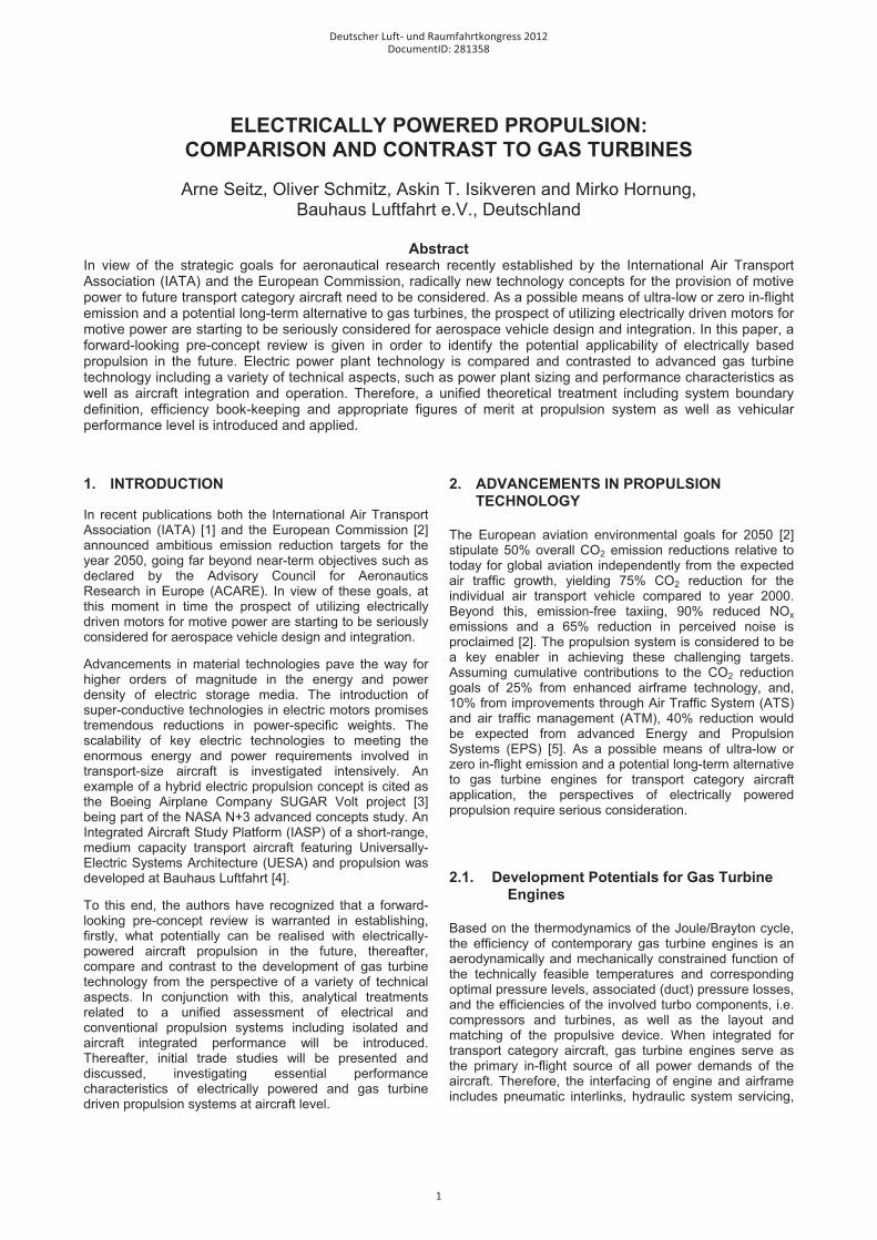
considered to contribute to the aircraft characteristics, thereby, feeding back to the thrust required to operate the aircraft system. In BILD 1, schematics of turbo fan and electric fan power plants are shown as half sections including markups of the relevant control volume definitions.
Fan & Drive System
Electric Motor
Gas Turbine
Power SupplySystemPower Transmission System
Control VolumesElectric Fan
Turbo Fan
BILD 1: Schematics of turbo fan and electric fan power plants including markups of control volume definitions
The overall efficiency of the EPS, �ov, is defined as the ratio of effective propulsive power, Pthrust, and power supplied by the energy source, Psupply:
prtrec
supplysupply
thrustov P
VFPP
���� ����
�� 00 (1)
where F0 denotes the net thrust of the installed power plant system and V0 represents the free stream velocity. As can be seen from Eq. (1), �ov is the product of energy conversion efficiency, transmission efficiency, and propulsive efficiency which are defined as follows:
jet
thrustpr
usable
jettr
supply
usableec P
PPP
PP
��� ��� ;; (2)
The energy conversion efficiency, �ec, incorporates the complete chain of energetic conversion between the energy source on-board the vehicle and the power usable to drive the propulsor, Pusable. The transmission efficiency, �tr, relates the power in the propulsive jet, Pjet, to Pusable. Finally, the ratio of effective propulsive power, Pthrust, and Pjet is captured by the propulsive efficiency.
In case of classical bypass turbofan engines, the efficiency of the power supply system, �ec, equals the core efficiency which is widely used in gas turbine performance programs, assuming negligible losses in the fuel system. As can be seen from BILD 1, core efficiency accounts for the High Pressure (HP) system including upstream effects of the core mass flow, such as the inner streamtube, intake and ducting losses, as well as, polytropic compression in the fan and low pressure compressor. Therefore, Pusable represents the ideal core excess power, available for the Low Pressure Turbine (LPT) to drive the outer fan, i.e. the part of the fan working on the bypass mass flow. The efficiency of the power transmission system, �tr, here, comprises the LPT, the Low Pressure (LP) shaft, an optional reduction gearbox system, the fan as well as all internal losses associated with the propulsive device, i.e.
outer streamtube, intake, bypass losses. It should be noted that for turbo fan engines, the power in the core nozzle jet may add considerably to Pjet, depending on the respective ByPass Ratio (BPR).
For an electrically driven fan, �ec may represent a variety of alternative efficiency chains, depending on the EPS concept: Considering UESAs, �ec incorporates the efficiency of the battery system, �Batt, the efficiency of the PMAD system, �PMAD, and, the efficiency of the controlled electric motor, �Mot:
MotPMADBattUESAec ���� ���, (3)
For a given battery system, �Batt is a function of state-of-charge and discharge rate. PMAD efficiency, �PMAD, is determined by individual efficiencies of the SSPC components. The electric motor efficiency, �Mot, includes the losses generated by the motor controller, i.e. the inverter device required for alternating current motors, as well as the necessary cryo-cooler for cryogenic or superconducting machines. In case of more complex EPS configurations such as serial turbo-electric architectures or hybrid energy supply layouts �ec should reflect the power-weighted efficiencies of all system components involved in the energy conversion between supplied and usable power.
The thermal efficiency of a shaft power engine, �th, relates the shaft power delivered to the fuel enthalpy flow introduced to the combustion chamber. Now, inspection of BILD 1 shows that �ec equals �th of a shaft power engine if the engine is independent from upstream effects, and, the residual net thrust of the engine exit mass flow, Fres, is zero. This is close to the real case of a turboshaft-powered propeller system. Unducted propulsive devices with zero or negligible Fres, however, intake, ducting and nozzle losses fall short and transmission efficiency, �tr, only reverts to the component efficiencies of the propulsor drive system, i.e. required shaft bearings and the optional gearbox system.
3.2. Definition of Figures of Merit
Conventional flight propulsion systems, i.e. turbofan or turboprop type power plants are comparable through the metric of Thrust Specific Fuel Consumption, TSFC, which is defined as the ratio of fuel flow and net thrust. When performing an assessment for electrically based propulsion systems the TSFC metric is not appropriate. Therefore, an enhancement of the TSFC metric is proposed, namely, the Thrust Specific Power Consumption, TSPC, which is introduced as [24]
prtrecov
supply VVFP
TSPC���� ��
��� 00
0
(4)
The TSPC metric relates the power supplied by the energy source, Psupply, to the net thrust produced, F0, independent from the type of power, i.e. fuel enthalpy flow or electrical power. TSPC incorporates the complete EPS efficiency chain as defined in the previous section. In case of
Deutscher Luft- und Raumfahrtkongress 2012
3
conventional heat engine cycles, TSPC is directly correlated to TSFC through the fuel heating value, FHV.
For propulsion system assessments at a vehicular level, metrics purely based on propulsion system efficiency, such as TSFC and TSPC, are insufficient. Hence, an aircraft-level figure of merit is required that is independent from the source of energy, similar to the TSPC metric at the propulsion system level. Therefore, the well-known Specific Air Range metric, SAR = dR/dm is extended to an Energy Specific Air Range, ESAR, given by [24]
gmDL
gmTSPCDLV
dEdRESAR
CA
ov
CA �
��
��
���
//
0 � (5)
where dR/dE represents the change of aircraft range per change of energy in the system and g is the gravity constant. The aircraft instantaneous properties are denoted by the lift-to-drag ratio, L/D, aircraft mass, mA/C, and the EPS overall efficiency, �ov. It should be noted that ESAR represents an instantaneous consideration of aircraft performance, and, L/D and �ov are functions of the operational conditions, namely, flight velocity V0 and altitude h, as well as transient and manoeuvre loads. In case mA/C varies with time, e.g. due to the consumption of fuel, L/D and �ov implicitly become functions of time. Hence, during detailed integrated mission evaluation, ESAR needs to be treated as a function of time due to the time dependencies of �ov, L/D and mA/C. For cruise optimality determination, however, ESAR represents a convenient figure of merit and was used for the aircraft-level studies presented in this paper.
3.3. Architectural Options for Full-Electric Power Plants
For the introduction of electrical energy as a source for propulsive power, a number of scenarios are conceivable including hybrid power solutions involving fuel cell-based, turboelectric or parallelised electric / kerosene-based system architectures, as well as sole battery-based energy storage. A schematic of the inferred morphological options is presented in Reference [17]. Now, introducing electrical energy into the scheme of aircraft propulsion power supply has significant implications to the overall aircraft design and characteristics, a brief discussion of which is given in Section 5.1 in this paper. The current section focuses on conceptual design options of the power plant, excluding PMAD architecture and energy storage, in the first instance.
Similar to kerosene-based propulsion systems, the production of thrust in case of electrical energy supply may be based on both ducted or unducted propulsive devices. Apart from classical shaft drive arrangements, electrically powered ducted propulsors could also be operated through quasi-linear or tip drive motors, such as discussed in References [25, 26, 27]. Moreover, the application of electrical drive trains may be a convenient means of facilitating efficient contra-rotating propulsor arrangements, allowing for the individual speed and torque control of the coaxial rotors which may lead to reduced noise emission.
The power density of rotating electrical machines is reduced by increasing torque density as a result of the required augmentation of electromagnetic forces. Therefore, high-speed electric motor designs will be favourable for airborne application [12]. In view of this, for conventional numbers of propulsors installed on the aircraft, gearbox systems are expected to be necessary to moderate the rotational speed of electric motors, as can be seen from the Silent Advanced Fan utilizing Electrical energy (SAFE) concept presented in Reference [4]. Different from classical gas turbine engines, the thrust reverser functionality may be realised through negative rotation of the electric motor, allowing for the omission of thrust reverser devices without necessitating complex blade pitch mechanisms on the propulsor.
The magnetic field strengh produced by superconducting coils may allow for the omission of the classic ironcores, and thereby, eliminate a conventional limit of rotor-produced field strengh rooted in the saturation characteristics of iron [20]. Such coreless rotor machines enable the highest torque densities of all types of electric machines [28], for high-speed motor application, however, rotor designs based on ferromagnetic alloys are often preferred due to the significantly lower excitation magnetomotive forces required [28]. HTS technology has been applied to both synchronous and induction / asynchronous electrical machines, however, practical application focuses on synchronous machines [28].
4. PROPULSION SYSTEM SIZING AND PERFORMANCE ASPECTS
Aiming at the Initial Technical Assessment (ITA) of full-electric EPS important design and operational aspects of electrically powered ducted fans were analysed as part of the presented work. In this section, firstly, the operational requirements for contemporary propulsion systems, and, intrinsic characteristics of air-breathing propulsion systems are reviewed. Subsequently, the challenges in designing full-electric power plant systems to performance are discussed, and, an Electric Fan (EF) propulsion concept is compared and contrasted to gas turbine engines in initial sizing and operational performance studies. Finally, a comparative assessment of power plant weights is given and noise trend indicators are discussed.
4.1. Review of Gas Turbine Engine Characteristics
State-of-the-art turbofan engines for transport category aircraft nearly reach overall efficiencies of �ov=0.4 at cruise conditions, i.e. propulsive efficiencies of approximately �pr=0.8 and thermal efficiencies around �ec·�tr=0.5. Here, the energy conversion efficiency, �ec, is a result of the technically feasible cycle temperature level, the correspondingly optimal compressor pressure ratios, ducting and mechanical losses, and, the core engine turbo component efficiencies. Transmission efficiency, �tr, is dominated by fan and LPT component efficiencies. An important design degree of freedom in order to reduce the overall specific thrust of the propulsion system, and
Deutscher Luft- und Raumfahrtkongress 2012
4
thereby, increasing the propulsive efficiency, �pr , of ducted air breathing engines is the BPR, i.e. the amount of inlet air mass flows passing through the bypass duct relative to the core engine mass flow. In practice, however, design BPR is subject to multiple constraints emanating from aircraft integration aspects or propulsion system internal implications depending on the system architecture [23].
The sizing of aero propulsion systems is driven by aircraft operational conditions, i.e. flight velocity and altitude, as well as atmospheric conditions, and the corresponding net thrust requirements. For conceptual design purposes, the operational requirements during Take-Off (T/O), at Top of Climb (TOC) conditions and during typical cruise are considered significant. At TOC conditions including aircraft required climb capability (e.g. 300ft/min), component corrected air mass flows or axial Mach numbers, respectively, are at maximum, therefore, constituting the relevant operational condition for flow path sizing. During T/O, typically, maximum cycle temperatures occur for turbofan engines, forming essential constraints for engine mechanical design involving choice of materials and turbine cooling system dimensioning. At a representative cruise condition, maximum efficiency is desired for minimum fuel consumption. Turbofan engine part power characteristics intrinsically facilitate improved efficiency at typical cruise thrust levels over flow path sizing thrust.
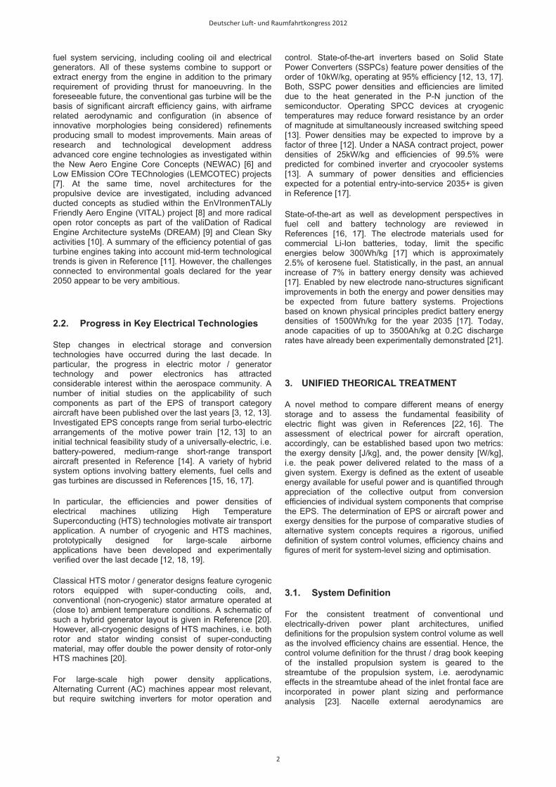
For typical operational requirements of subsonic transport aircraft, i.e. cruise Mach number and altitude, take-off and landing field lengths, and, required climb gradients in One Engine Inoperative (OEI) cases, power plant thrust requirements need to be harmonized with the intrinsic power lapse characteristics of gas turbine engines. In BILD 2, maximum power delivery characteristics of a 2-spool turboshaft engine are visualised for a representative subsonic flight envelope.
2 0 2 4 6 8 1
0
40 80
120 16
0 200
240
280
320
Rel
ativ
e M
axim
um S
haft
Pow
er [%
]
120
100
80
60
40
200 0.2 0.4 0.6 0.8 1.0
Operating Mach Number [-]
0.0
13
Operating Altitude [km]1.0
2.03.0
4.05.0
6.07.0
8.0
9.0
10
11
12Contours: Equivalent Air Speed [kts]Typical Cruise ConditionsStatic Sea Level (Reference Point)
Active Limiters:HPT inlet Temp (T41)HP mech. spool speedHP corr. spool speed
BILD 2: Typical power lapse characteristics of a turboshaft engine in relevant flight conditions, simulated using the software GasTurb11®.
The results shown in BILD 2 were simulated using the software GasTurb11® [29]. Typical rating settings including limiters for turbine entry temperature, T41, as well as High Pressure (HP) mechanical and aerodynamic spool speeds were assumed. Normalised for Static Sea Level (SLS) power, the figure displays the partial dependencies of shaft power delivered against varying operational Mach numbers and altitudes. The gain in power output with increasing operating Mach number emanates from ram
pressure recovery and the correspondingly increased air mass flow rates, accompanied by cycle efficiency effects due to the higher overall pressure levels. Peak power at sea level is approximately 12% above static power capacity. The reduction in air density with increasing altitude, in turn, significantly lowers power output capacity. As a result, a maximum relative power capacity of approximately 45% at typical cruise conditions is obtained, which directly translates to the maximum thrust levels required at TOC/cruise conditions relative to T/O.
For given technology level and thrust requirements, the thrust specific weight of turbofan power plants is a function of specific thrust, driven by the corresponding variation in fan diameter. The power specific weight of turbofan core engines as part of the overall power plant is essentially driven by the throughput of air mass flow, as well as the temperature and pressure levels projected. Numbers for the thrust or power specific power plant weight, therefore, may vary significantly depending on the design specification. System weight prediction, in the present paper, is issued in Section 4.6.
4.2. New Challenges Connected to Electric Power Plant Sizing and Performance
The sizing and performance matching of universally-electric EPSs for transport category aircraft involves an extended set of considerations necessary and challenges to be overcome, even if the paramount issues of system energy and power density are assumed to be solved. In this section, the critical sizing cases of universally-electric EPS components, and, the matching of the propulsor and the electric motor for an EF application are discussed in brief.
The maximum power output of electrical motor, as opposed to the previously reviewed turbo engines, may be considered as independent from operating altitude and Mach number, provided motor thermal environment is controlled appropriately. In an EF arrangement, convective heat transfer through the fan mass flow may be conveniently utilized for conventional motor thermal management. The abstraction of heat loads due to HTS technology application requires cryo-cooling which will be issued in the next section.
The critical sizing case for an electric motor is defined by the operating condition that requires the highest power input to the propulsor driven. Particularly, in a twin-engine aircraft arrangement the thrust requirements at minimum V2 safety speed and associated gradient with OEI typically dictate the required electric motor power. The critical case for PMAD system sizing, usually, refers to the overall maximum power required in case of All Engines Operative (AEO) [4]. The individual criticality of the different sizing cases may be influenced significantly by changing levels of system redundancy, e.g. the number of power plants installed on the aircraft, or, the potential allowance of mechanical cross-couplings of installed propulsors. During PMAD sizing, however, the potential capability of motor short duration over-powering for emergency operation, e.g. in case of OEI, requires adequate consideration.
Due to the diminished power lapse with increasing altitude, in contrast to classical air-breathing engines, typical TOC
Deutscher Luft- und Raumfahrtkongress 2012
5

and cruise conditions imply strong part load operation of electric motors (also cf. BILD 2 as an analogue). However, if combined with a variable nozzle device or variable pitch fan blades, electric motors may offer improved operational flexibility over conventional turbo engines. The part power efficiency characteristics of electrical motors, i.e. the location of peak efficiency and the shape of efficiency contours within the speed / torque map, strongly depend on its electromagnetic design as can be seen in Reference [30]. HTS motors, in general, exhibit very high efficiencies across a broad range of partial power loading [28]. Hence, adequate flexibility during part load operation may be expected.
Flow path sizing of the propulsive device, still follows the classical limitations of maximum corrected specific mass flows, i.e. component axial Mach numbers and rotational speeds. Due to the shortfall of in-flight weight loss for universally-electric aircraft, aerodynamic design tailoring of ducted propulsors, i.e. single or contra-rotating fans, may follow new rules. In BILD 3, the differences in fan aerodynamic sizing and performance between conventional and universally-electric aircraft application is sketched.
Fan
Pres
sure
Rat
io (F
PR) [
-]
Corrected Massflow (W2RStd) [kg/s]
Flow Path Sizing Point (TOC)
Typical Cruise Conventional Aircraft
Typical Cruise Electric Aircraft
Ncorr=1.00.950.90.85
0.80.7
0.5
BILD 3: Fan sizing and performance matching for universally-electric aircraft
As can be seen in BILD 3, on the fan component map, a typical cruise operating point of conventional medium range (M/R) aircraft is clearly separated from the fan sizing point. This results from the reduced cruise thrust requirements relative to the flow path sizing thrust. Although not matching fan peak efficiency, the representative cruise condition is reflected by optimal TSPC, due to the superposition of all turbo component off-design characteristics of the entire power plant. In contrast, the fan operating point of universally-electric aircraft during cruise would be located much closer to the component sizing point, thereby, deviating stronger from maximum fan efficiency.
Here, fan oversizing could improve component operational efficiency. At the same time this could improve product family design range. However, the trade-off between improved fan efficiency, and, increments in propulsive device mass and nacelle drag has to be evaluated carefully. Hence, fan aerodynamic design should be tailored to exhibit maximum efficiencies at high map speeds.
4.3. HTS Motor Efficiency Description
The energy conversion efficiency, �ec, of a universally electric EPS is generally higher than for a heat engine, due to the high exergy content of the energy source. However, detailed book-keeping of the losses occurring in the electrical components is vital for an initial technological assessment. In particular, if EPS components are operated cryogenically, the refrigeration of the dissipative heat produced at the cryogenic temperature levels represents a critical challenge for system design [31, 32].
The losses in electrical machines may be categorised as
� ohmic losses in the rotor and stator, � core losses, i.e. eddy current losses and
hysteretic losses � friction and windage losses, and, � stray and miscellaneous losses.
HTS technology facilitates loss reductions in all of these categories, but primarily diminishes ohmic losses. However, residual Joule and AC heating effects of the HTS components, in conjunction with conductive, convective and radiative heat transfers within the system [31], have to be abstracted from the system. The energy balance of a superconductor carrying transport current in a magnetic field is discussed in Reference [33]. The heat loads dissipated at cryogenic temperatures in HTS electrical machines, typically, range between 10-4 and 10-5 relative to the rated motor power [31, 32, 19].
Unless cryogenic fuel can be utilised as a sink for the dissipative heat power, Pload, requires cryogenic cooling devices. The required input power for the refrigeration system, Pinput, is related to Pload through a cooling performance coefficient, i.e. Ccool = Pinput/Pload = CCarnot/�mech, where the Carnot efficiency factor is defined as CCarnot = (Tsink-Tload)/Tload. The efficiency number �mech is a catch-all term incorporating all mechanical non-idealities of the cooling system. Tsink denotes the temperature of external heat abstraction. Assuming state-of-the-art external thermal insulation and stationary system operation at Tload, cryocooler sizing power, Pload, focuses on the heat losses of the HTS component to be cooled, i.e Pload = (1- �HTS.)·PHTS, where �HTS and PHTS represent the bare efficiencies and power input of the considered HTS component, respectively.
Taking appropriate temperature levels for Tsink and Tload with respect to transport aircraft systems design, and considering realistic values for �mech (30% acc. to Reference [13]), it can be seen that the required cryocooler power input amplifies the efficiency impact of cryogenic losses significantly. Incorporating the required input power of the cryocooler, Pinput, the efficiency of cooled HTS electric motors can be expressed as a function of motor bare efficiency, i.e. without cooling, �Mot,bare, and Ccool:
� �11 ,,
,
, �
���� bareMotMot
MotcoolbareMot
iMot
oMotMot C
PP
�
�� (6)
where �Mot represents the ratio of cryogenic heat losses, Ploss,cyro, to all other losses, Ploss,res, in the motor. Efficiency characteristics of HTS machines versus power and torque delivered are presented in Reference [28]. Accordingly,
Deutscher Luft- und Raumfahrtkongress 2012
6

efficiency remains almost unaffected between 5% and 100% rated power for the shown synchronous motor. Similarly, efficiency characteristics appear widely independent against varying torque between approximately 20% and 100% rated output. Therefore, the detailed description of HTS motor losses as functions of the motor operational condition, and, the analytical mapping of part power efficiency characteristics is not further elaborated, here. However, Eq. (6) may be adopted for the initial efficiency estimation of cryogenically cooled components of the PMAD system by using the corresponding bare efficiencies, operating temperatures and cryogenic loss ratios.
4.4. Initial Design Investigation
In order to compare and contrast the characteristics of aircraft power plants featuring electrically driven fans to turbofan propulsion systems, an initial study at flow path sizing conditions, i.e. maximum climb rating at TOC conditions, was performed.
The EF power plant concept was analysed against 2 gas turbine architectures, Direct Drive (DD-TF) and Geared Turbofan (G-TF), with respect to the TSPC efficiency metric introduced before. For both gas turbine based power plant concepts, typical design laws were applied for cycle and flowpath sizing, including iterations for design streamtube thrust, the Overall Pressure Ratio (OPR), outer and inner Fan Pressure Ratios (FPRs), fan tip speed, as well as the nozzle thrust and discharge coefficients [23, 34]. The efficiencies of the core engine turbo components were computed using the methods presented in Reference [23], i.e. incorporating the individual aerodynamic loading conditions resulting from the flow path design. It was assumed that fan design may be tailored to yield constant design polytropic efficiencies for the parametric studies performed. The assumption was consistently adopted for all power plant architectures investigated in the paper.
The cycle temperature levels of the gas turbines, turbo component aerodynamic losses, as well as ducting pressure losses were adjusted to reflect technology status 2030. Consistent High Pressure Turbine (HPT) cooling settings were adopted for all gas turbine designs investigated, based on the approach presented in Reference [23]. LPTs were considered to be uncooled. The losses of Fan Drive Gearbox Systems (FDGS), intrinsic to power plant architectures with a geared propulsive device, were incorporated in the definition of mechanical component efficiencies. The corresponding FDGS gear ratios result from the asynchronism of fan rotational speed and the rotational speed of the driving component, i.e. the LPT for G-TF architectures or the electric motor in case of an EF. For the studies presented in the following, the LPT mean circumferential velocities of the investigated G-TF designs were retained constant. A summary of important invariant design settings for the power plant concepts investigated in the paper is given in TAB 1. Accordingly, the stage counts, nst, of the Intermediate Pressure Compressors (IPC), the HPTs and the LPTs, was well as IPC pressure ratios, �IPC, of the DD-TF and G-TF power plants were prescribed. For the EF concept, Ploss,cyro in the electric motor were considered to be 5% relative to Ploss,res, while motor bare efficiency is
assumed to be 99.5%.
TAB 1: Constant settings for power plant design studies
Unit DD-TF G-TF E-Fan
�Fan,poly [%] 94.0 94.0 94.0 T4 [K] 1800 1800 n/a OPR [-] 52 52 n/a �IPC [-] 2.0 2.4 n/a nSt,IPC [-] 5 3 n/a nSt,HPT [-] 2 2 n/a nSt,LPT [-] 7 3 n/a FHV [MJ/kg] 43 43 n/a TMot,HTS* [K] n/a n/a 77 Tsink** [K] n/a n/a 308 �Mot,bare [%] n/a n/a 99.5 �Mot [-] n/a n/a 0.05 �PMAD [%] n/a n/a 99.0 �Batt [%] n/a n/a 90.0
* corresponds to Tload required for Eq. (6) ** assumed to be ISA+20K at sea level
Design and off-design performance simulations for the DD-TF and G-TF engines were conducted using the software GasTurb11®. Since GasTurb11® does not allow for a convenient simulation of electric EPS concepts, the EF simulation was performed based on an in-house developed Aircraft Propulsion System Simulation (APSS) framework [35] implemented in Matlab® [36]. APSS allows for the generic configuration of novel propulsion concepts, such as hybrid and full-electric systems. All integrated methods for conventional propulsion components, such as compressors, turbines, ducts, nozzles and mechanical components, have been verified against GasTurb11®.
In BILD 4, TSPC characteristics of EF, DD-TF and G-TF designs at flow path sizing conditions are presented. The shown design study covers a broad range of design specific thrust, FN/Wdes. For both turbofan architectures, the corresponding design BPRs are annotated. All power plants were sized for a streamtube thrust of 30kN at typical TOC conditions (M0.78/FL350) for a Short Range (S/R) air transport application, using the technology settings listed in TAB 1.
20 40 60 80 100 120 140 160 180 200 220
350
400
450
500
550
600
650
Electric FanDFan=5.53m
3.59m 2.86m 2.45m2.17m
1.97m1.82m
DD-TF
67
89101112131416BPR=18
G-TF10
12141618202530BPR=40
Study Settings:Streamtube Sizing Thrust 30kNConditions: ISA, M0.78, FL350Fan Polytropic Efficiency: 0.94
Design Specific Thrust FN/Wdes [m/s]
TSP
C [W
/N]
BILD 4: Design TSPC comparison of DD -TF, G-TF and EF propulsion concepts
It can be seen from BILD 4, that when comparing stationary comparing stationary the EF concept shows a reduction in the TSPC metric of approximately 43%
Deutscher Luft- und Raumfahrtkongress 2012
7
compared to the DD-TF, and a corresponding reduction of 39% relative to the G-TF architecture at optimum FN/Wdes. These deltas are rooted in the significantly different efficiency chain of the EF propulsion concept. The relative improvement of the G-TF over the DD-TF architecture with respect to optimum design TSPC yields approximately 6.5%. The corresponding optimum �ov levels yield 38.5% for the DD-TF, 41.2% for the G-TF, and, 67.9% for the EF concept.
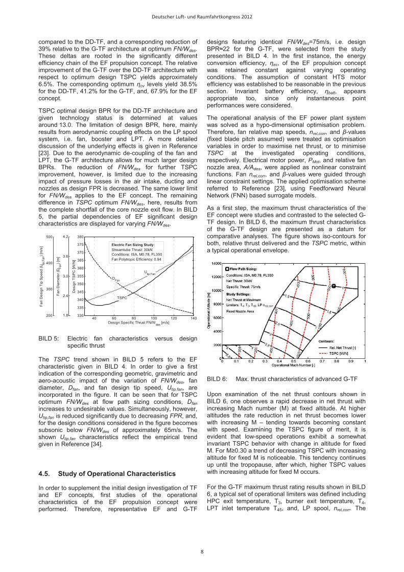
TSPC optimal design BPR for the DD-TF architecture and given technology status is determined at values around 13.0. The limitation of design BPR, here, mainly results from aerodynamic coupling effects on the LP spool system, i.e. fan, booster and LPT. A more detailed discussion of the underlying effects is given in Reference [23]. Due to the aerodynamic de-coupling of the fan and LPT, the G-TF architecture allows for much larger design BPRs. The reduction of FN/Wdes for further TSPC improvement, however, is limited due to the increasing impact of pressure losses in the air intake, ducting and nozzles as design FPR is decreased. The same lower limit for FN/Wdes applies to the EF concept. The remaining difference in TSPC optimum FN/Wdes, here, results from the complete shortfall of the core nozzle exit flow. In BILD 5, the partial dependencies of EF significant design characteristics are displayed for varying FN/Wdes.
40 60 80 100 120 140330
335
340
345
350
355
360
365
370
375
380
Design Specific Thrust FN/Wdes [m/s]
Des
ign
TSP
C [W
/N]
TSPC
Electric Fan Sizing Study:Streamtube Thrust: 30kNConditions: ISA, M0.78, FL350Fan Polytropic Efficiency: 0.94
DFan
1.8
2.4
3.0
3.6
4.2
Fan
Dia
met
er (D
Fan) [
m]
Utip,Fan
200
300
400
500
Fan
Des
ign
Tip
Spe
ed (U
tip,F
an) [
m/s
]
BILD 5: Electric fan characteristics versus design specific thrust
The TSPC trend shown in BILD 5 refers to the EF characteristic given in BILD 4. In order to give a first indication of the corresponding geometric, gravimetric and aero-acoustic impact of the variation of FN/Wdes, fan diameter, Dfan, and fan design tip speed, Utip,fan, are incorporated in the figure. It can be seen that for TSPC optimum FN/Wdes at flow path sizing conditions, Dfan
increases to undesirable values. Simultaneously, however, Utip,fan is reduced significantly due to decreasing FPR, and, for the design conditions considered in the figure becomes subsonic below FN/Wdes of approximately 65m/s. The shown Utip,fan characteristics reflect the empirical trend given in Reference [34].
4.5. Study of Operational Characteristics
In order to supplement the initial design investigation of TF and EF concepts, first studies of the operational characteristics of the EF propulsion concept were performed. Therefore, representative EF and G-TF
designs featuring identical FN/Wdes=75m/s, i.e. design BPR�22 for the G-TF, were selected from the study presented in BILD 4. In the first instance, the energy conversion efficiency, �ec, of the EF propulsion concept was retained constant against varying operating conditions. The assumption of constant HTS motor efficiency was established to be reasonable in the previous section. Invariant battery efficiency, �batt, appears appropriate too, since only instantaneous point performances were considered.
The operational analysis of the EF power plant system was solved as a hypo-dimensional optimisation problem. Therefore, fan relative map speeds, nrel,corr, and �-values (fixed blade pitch assumed) were treated as optimisation variables in order to maximise net thrust, or to minimise TSPC at the investigated operating conditions, respectively. Electrical motor power, PMot, and relative fan nozzle area, A/Ades, were applied as nonlinear constraint functions. Fan nrel,corr, and �-values were guided through linear constraint settings. The applied optimisation scheme referred to Reference [23], using Feedforward Neural Network (FNN) based surrogate models.
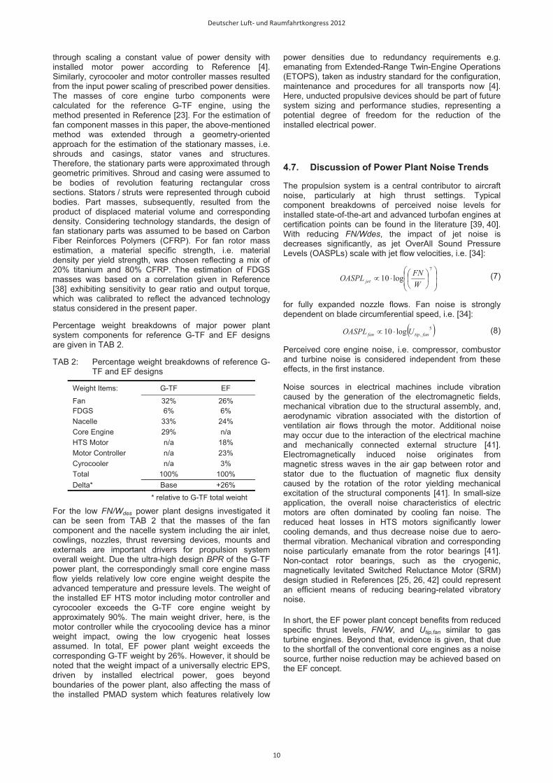
As a first step, the maximum thrust characteristics of the EF concept were studies and contrasted to the selected G-TF design. In BILD 6, the maximum thrust characteristics of the G-TF design are presented as a datum for comparative analyses. The figure shows iso-contours for both, relative thrust delivered and the TSPC metric, within a typical operational envelope.
BILD 6: Max. thrust characteristics of advanced G-TF
Upon examination of the net thrust contours shown in BILD 6, one observes a rapid decrease in net thrust with increasing Mach number (M) at fixed altitude. At higher altitudes the rate reduction in net thrust becomes lower with increasing M – tending towards becoming constant with speed. Examining the TSPC figure of merit, it is evident that low-speed operations exhibit a somewhat invariant TSPC behavior with change in altitude for fixed M. For M�0.30 a trend of decreasing TSPC with increasing altitude for fixed M is noticeable. This tendency continues up until the tropopause, after which, higher TSPC values with increasing altitude for fixed M occurs.
For the G-TF maximum thrust rating results shown in BILD 6, a typical set of operational limiters was defined including HPC exit temperature, T3, burner exit temperature, T4, LPT inlet temperature T45, and, LP spool, nrel,corr. The
Deutscher Luft- und Raumfahrtkongress 2012
8

temperature levels and corresponding turbine cooling air requirements were adjusted to match typical thrust lapse characteristics between T/O and flow path sizing conditions. For T/O, M0.2 at sea level and ISA temperature was considered representative. A fixed fan nozzle area was considered. The operational characteristics of the G-TF architecture refer to GasTurb11® simulation results. Component off-design characteristics were represented by the standard component maps supplied with the software. For the comparative study of the EF concept presented in BILD 7, identical fan map characteristics were adopted, in the first instance.
BILD 7: Max. thrust characteristics of EF concept
BILD 7 features an identical setup as BILD 6, supplemented by iso-contours for the relative electric motor power, PMot,rel, which is defined as the maximum rated motor power related to the motor power at flow path sizing conditions. The maximum limit for the EF design, nrel,corr, was defined identical to the referenced G-TF engine. Maximum (installed) motor power, PMot,rel,max, was chosen to match the reference G-TF thrust at the representative T/O conditions defined before.
An interesting comparison and contrast can be made between the contour plots given in BILD 6 and BILD 7, namely, between the advanced G-TF and EF design, respectively. Common trending features between both approaches to propulsion include restricted altitude operations for low-speed cases, and, for M�0.30 decreasing TSPC with increasing altitude for fixed M. Focusing on lower altitudes and lower speeds, the impact of having an electrical motor as a means of propulsion becomes distinct. On the positive side, in view of motor power invoking an active limit less pronounced thrust lapse occurs for the EF design. The amelioration of thrust lapse is considered as being minor-to-modest for en route operations; however, for altitudes below 1000 m (~3000ft) the degree of thrust lapse mitigation is considered significant. When observing general behavior of rate reduction in net thrust with M for fixed altitude above 3000ft, it can be stated that EF characteristics are similar to the G-TF. For the low-speed regime, a more noticeable invariance of TSPC behaviour with change in altitude for fixed M is associated with the EF concept. The trend of decreasing TSPC with increasing altitude for M�0.30 and the corresponding trend inflection beyond the tropopause is less pronounced for the EF design.
As part of presented work, an initial set of degrees of freedom for the reduction of PMot,rel,max were investigated: The effect of variability of the fan nozzle area, expressed as the maximum allowable nozzle area relative to the nozzle area at flow path sizing conditions, A/Ades, is visualised in BILD 8. Also shown in the figure is the corresponding impact of different design specific thrust settings, FN/Wdes. The arrangement of the figure facilitates an evaluation of the trade-off between fan size, i.e. fan diameter, Dfan, and installed electric motor power, required to deliver the predefined thrust at T/O conditions (ISA, M0.2, Sea Level). Inspection of the figure shows that an extension of fan nozzle area, i.e. A/Ades>1, represents an effective means of reduction installed motor power. Accordingly, an increment of A/Ades by 15% yields 7.8% reduced PMot,rel,max. Simultanenously decreasing FN/Wdes to 60m/s yields a cumulative reduction of PMot,rel,max by 12.8%.
2.2 2.4 2.6 2.8 32
2.1
2.2
2.3
2.4
2.5
2.6
2.7
60m/s
70m/s
80m/s
FN/Wdes= 90m/s
A/Ades= 98%
100%
105%
110%
115%
Fan Diameter (DFan) [m]
Rel
. Mot
or P
ower
Lim
it (P
Mot
,rel) [
-]
Study Settings:
Free Parameters: FN/Wdes, A/Ades:
Net Thrust Fixed at ISA, M0.2, Sea LevelBetaFan, nrel,corr,Fan at Optimum for Min. Motor Power
Reference Design:
Flow Path Sizing at ISA, M0.78, FL350Fixed Nozzle, FN/Wdes=75m/s
BILD 8: Effect of design specific thrust and relative fan nozzle area on the required relative motor power for given take-off thrust requirement
The characteristics displayed in BILD 8 are bounded by the linear constraint settings of fan �-values and nrel,corr, however, in order to establish more detailed technical feasibility for the operation of low specific thrust fan designs at variable nozzle throttle conditions requires a considered investigation of fan surge and choking behaviour.
Further reductions of PMot,rel,max without compromising fixed TOFL constraints, however, may be realised through distributed electric propulsion [37]. Future studies should emphasis on integrated low-speed performance studies, in order to comprehensively evaluate the minimum PMot,rel,max for varies Take-Off Field Length (TOFL) requirements. Furthermore, analyses should investigate the impact of varying flow path design Mach numbers and altitudes on the relative required electric motor power in order to fulfill T/O performance goals.
4.6. Comparative Assessment of Weights
In order to facilitate later concept evaluation at a vehicular level, an initial comparative assessment of propulsion system weights was performed for G-TF and EF power plant designs analysed in the previous section. In the first instance, HTS electric motor masses were estimated
Deutscher Luft- und Raumfahrtkongress 2012
9
through scaling a constant value of power density with installed motor power according to Reference [4]. Similarly, cyrocooler and motor controller masses resulted from the input power scaling of prescribed power densities. The masses of core engine turbo components were calculated for the reference G-TF engine, using the method presented in Reference [23]. For the estimation of fan component masses in this paper, the above-mentioned method was extended through a geometry-oriented approach for the estimation of the stationary masses, i.e. shrouds and casings, stator vanes and structures. Therefore, the stationary parts were approximated through geometric primitives. Shroud and casing were assumed to be bodies of revolution featuring rectangular cross sections. Stators / struts were represented through cuboid bodies. Part masses, subsequently, resulted from the product of displaced material volume and corresponding density. Considering technology standards, the design of fan stationary parts was assumed to be based on Carbon Fiber Reinforces Polymers (CFRP). For fan rotor mass estimation, a material specific strength, i.e. material density per yield strength, was chosen reflecting a mix of 20% titanium and 80% CFRP. The estimation of FDGS masses was based on a correlation given in Reference [38] exhibiting sensitivity to gear ratio and output torque, which was calibrated to reflect the advanced technology status considered in the present paper.
Percentage weight breakdowns of major power plant system components for reference G-TF and EF designs are given in TAB 2.
TAB 2: Percentage weight breakdowns of reference G-TF and EF designs
Weight Items: G-TF EF
Fan 32% 26% FDGS 6% 6% Nacelle 33% 24% Core Engine 29% n/a HTS Motor n/a 18% Motor Controller n/a 23% Cyrocooler n/a 3% Total 100% 100% Delta* Base +26%
* relative to G-TF total weight
For the low FN/Wdes power plant designs investigated it can be seen from TAB 2 that the masses of the fan component and the nacelle system including the air inlet, cowlings, nozzles, thrust reversing devices, mounts and externals are important drivers for propulsion system overall weight. Due the ultra-high design BPR of the G-TF power plant, the correspondingly small core engine mass flow yields relatively low core engine weight despite the advanced temperature and pressure levels. The weight of the installed EF HTS motor including motor controller and cyrocooler exceeds the G-TF core engine weight by approximately 90%. The main weight driver, here, is the motor controller while the cryocooling device has a minor weight impact, owing the low cryogenic heat losses assumed. In total, EF power plant weight exceeds the corresponding G-TF weight by 26%. However, it should be noted that the weight impact of a universally electric EPS, driven by installed electrical power, goes beyond boundaries of the power plant, also affecting the mass of the installed PMAD system which features relatively low
power densities due to redundancy requirements e.g. emanating from Extended-Range Twin-Engine Operations (ETOPS), taken as industry standard for the configuration, maintenance and procedures for all transports now [4]. Here, unducted propulsive devices should be part of future system sizing and performance studies, representing a potential degree of freedom for the reduction of the installed electrical power.
4.7. Discussion of Power Plant Noise Trends
The propulsion system is a central contributor to aircraft noise, particularly at high thrust settings. Typical component breakdowns of perceived noise levels for installed state-of-the-art and advanced turbofan engines at certification points can be found in the literature [39, 40]. With reducing FN/Wdes, the impact of jet noise is decreases significantly, as jet OverAll Sound Pressure Levels (OASPLs) scale with jet flow velocities, i.e. [34]:
���
���
���
�����
7
log10WFNOASPL jet (7)
for fully expanded nozzle flows. Fan noise is strongly dependent on blade circumferential speed, i.e. [34]:
� �5,log10 fantipfan UOASPL �� (8)
Perceived core engine noise, i.e. compressor, combustor and turbine noise is considered independent from these effects, in the first instance.
Noise sources in electrical machines include vibration caused by the generation of the electromagnetic fields, mechanical vibration due to the structural assembly, and, aerodynamic vibration associated with the distortion of ventilation air flows through the motor. Additional noise may occur due to the interaction of the electrical machine and mechanically connected external structure [41]. Electromagnetically induced noise originates from magnetic stress waves in the air gap between rotor and stator due to the fluctuation of magnetic flux density caused by the rotation of the rotor yielding mechanical excitation of the structural components [41]. In small-size application, the overall noise characteristics of electric motors are often dominated by cooling fan noise. The reduced heat losses in HTS motors significantly lower cooling demands, and thus decrease noise due to aero-thermal vibration. Mechanical vibration and corresponding noise particularly emanate from the rotor bearings [41]. Non-contact rotor bearings, such as the cryogenic, magnetically levitated Switched Reluctance Motor (SRM) design studied in References [25, 26, 42] could represent an efficient means of reducing bearing-related vibratory noise.
In short, the EF power plant concept benefits from reduced specific thrust levels, FN/W, and Utip,fan similar to gas turbine engines. Beyond that, evidence is given, that due to the shortfall of the conventional core engines as a noise source, further noise reduction may be achieved based on the EF concept.
Deutscher Luft- und Raumfahrtkongress 2012
10
5. AIRCRAFT INTEGRATED PERFORMANCE AND SIZING
The power plant level assessment of electrically powered aircraft propulsion previously presented will be extended to the aircraft level in present section. Therefore, important aircraft integration aspects intrinsic to universally-electric propulsion are reviewed, before the results of a comparative performance study of EF and G-TF powered aircraft are presented and discussed.
5.1. Review of Electric Propulsion Integration Aspects
Classic propulsion system design implications on the overall aircraft layout and sizing include a variety of geometric, structural, aerodynamic and performance-related effects [23]. The adoption of electrically powered propulsion systems would produce marked differences in both the design and operation of aircraft compared to traditional gas turbine based propulsion. In the following, important aspects are discussed in brief.
In the foreseeable future, the energy density of batteries will remain clearly lower than for kerosene fuel. Therefore, the paramount implication of universally electric EPSs will be the significantly reduced range capacities relative to conventionally powered aircraft. As was determined in the previous section, the power densities and thrust specific weights of EF power plants exhibit significant but not prohibitively high penalties over advanced turbofan engines. However, the replacement of the conventional fuel system by an electric PMAD system involves significant further weight added to the aircraft, especially if ETOPS requirements have to be met [4]. Moreover, as opposed to conventional energy storage, namely by fuel, the gravimetric power density of electrical energy storage through batteries is limited. Hence, a minimum is battery mass share of the aircraft gross weight is required in order to allow the aircraft to take off within reasonable TOFL.
Vehicular operation of universally-electric aircraft differs significantly from conventional systems due to the shortfall of in-flight weight reduction. Constant weight during the entire mission would preclude the notion of common en route procedures such as step-cruising.
Electric energy supply and conversion particularly facilitates distributed propulsion integration which enables new degrees of freedom for airframe structural optimisation, and thus, may lead to new efficient aircraft layouts [27, 37]. Through UESA application, the classical customer off-takes from the power plant system fall short. However, electro-magnetic shielding effort is considerably elevated.
Due to a universally-electric EPS, major changes to aircraft balance, loadability, maintenance procedures, bill-of-material/maintenance costs, aircraft ground servicing and impact to turn-around time performance are posited to
occur [4]. HTS technology relies on cryocooling in order to prevent electrical quenching, and thus, loss of operability. Adequate redundancy, therefore, has to be incorporated in the system design.
The replacement of a gas turbine core engine by HTS electric motors, finally, influences the external noise characteristics of the aircraft, potentially offering the capability of significant noise reduction when combined with a ducted propulsive device.
5.2. Vehicular Performance Implications
In order to assess the aircraft-level impact of the EF power plant concept, first vehicular performance analyses were conducted using the ESAR figure of merit. Therefore, the design of the EF concept studied in the previous section was matched with the universally-electric, short-range, mid-sized aircraft concept design presented in Reference [4]. The properties of the aircraft-installed EF concept were then compared and contrasted to the vehicular performance properties of a G-TF powered aircraft also featuring advanced technology corresponding to an EIS year 2035. The Maximum Take-Off Weight (MTOW) of the universally electric aircraft exceeded the conventional reference aircraft by approximately 49%, due to the high weight shares of the electric energy storage and PMAD systems [4]. However, in this instance, both investigated aircraft featured identical aerodynamic polars and maximum wing loadings, MTOW/Sref. The Instantaneous Gross Weight (IGW) of the conventional S/R aircraft was assumed to be 95% of MTOW, while IGW equaled MTOW for the universally-electric aircraft.
For both aircraft concepts, vehicular performance quality, namely ESAR, was investigated within a typical cruise envelope, constrained by buffet limits, power plant thrust limits and maximum operating Mach number, MMO. Analogous to the studies of propulsion system isolated performance (Section 4.5), aircraft operational analysis was treated as a hypo-dimensional optimisation problem. While maximum ESAR was taken as the objective function, the matching of power plant thrust and aircraft drag for stationary level flight was handled as a nonlinear equality constraint. For the EF concept, again, nrel,corr, and �-values used as optimisation variables, while fan nozzle area was retained constant. Correspondingly, nrel,corr, was varied in order to optimise ESAR for the G-TF powered aircraft.
Operating altitude and Mach number represented free study parameters. Operational envelope limitations were superimposed as post-optimisation constraints. For both power plant concepts, maximum thrust at cruise was assumed to be limited by fan map speed, nrel,corr=1. Identical lift coefficient limits for 1.3g buffet onset as a function on operating Mach number were used. In both cases, MMO was 0.82. The integrated results of the aircraft level performance comparison of the EF and G-TF power plants are presented in BILD 9.
Deutscher Luft- und Raumfahrtkongress 2012
11

Colour Code
Rel. ESAR [-]Fan nrel,corr [-]1.3g Buffet LimitThrust LimitMMO [-]
Air Transport Task
Max. Payload: 189PaxDesign Range: 900nm
Initial Cruise Alt.: FL330Design Cruise M: 0.75
Power Plant FN/Wdes: 75m/s
Electric Aircraft (Dashed Lines)
MTOW: 109.3tCruise Gross Weight / MTOW: 100%
Peak ESAR: 13.6m/MJ
Conventional Aircraft (Solid Lines)
MTOW: 73.3tCruise Gross Weight / MTOW: 95%
Peak ESAR: 12.3m/MJ
BILD 9: Comparison of vehicular efficiencies for EF and advanced G-TF powered aircraft
The contour plots presented in BILD 9 are quite insightful in the sense the observer can compare and contrast the relative impact G-TF and EF installations have at aircraft level whilst at the same time formulate conclusions relevant to flight planning. Upon inspection of peak ESAR values, the EF produces an improvement over the G-TF of 10.6%. The peak ESAR operating points correspond to practical cruise flight techniques of M0.74/FL350 for the G-TF and M0.68/FL290 for the EF. For a typical 500 nm stage length the reduction of 5.6% in cruise True Airspeed (TAS) equates to approximately 3-4 min. longer flight for the aircraft utilizing EF. Although it is plausible to accept the trade-off between significant improvement in ESAR and the slight increase in block time, cruise at FL 290 is considered to be a disadvantage because it does not permit over-the-weather operation (generally accepted as being above FL310). If instead one examines the standard practice of flying a Long-Range Cruise (LRC) flight technique, usually taken as 99% of max ESAR, a practical LRC flight technique of the EF would be M0.72/FL330 and M0.76/FL350 for the G-TF. For the same improvement in ESAR quoted above the reduction in TAS now becomes 4.6% and is equivalent to an increase of only 2 min. in block time for the EF. A final comparison of interest is to now choose a common Mach-altitude flight technique and compare both types of propulsion. Assuming a common flight technique of M0.75/FL330, the EF equipped aircraft would operate at 98% max ESAR, whereas, the G-TF aircraft would corresponding to a condition of 99% max ESAR. Even though there exists a noticeable difference in relative ESAR for each respective propulsion type the relative difference in terms of absolute ESAR still displays a significant difference of 8.6% improvement in favour of the EF equipped aircraft.
6. CONCLUSION AND FUTURE WORK
In the present paper, the pre-concept assessment of electrically powered aircraft propulsion was elaborated and the potential applicability to future air transport task was investigated. Motivated by the possible prospect of zero in-flight emissions, and, through the observed progress and perspectives in key electrical technologies, an Electric Fan (EF) power plant concept was compared and contrasted to advanced turbofan engines, at the isolated power plant level as well as at the integrated vehicular level. In order to establish a unified basis for the comparison of the investigated conventional and universally-electric Energy and Propulsion Systems (EPSs), appropriate figures of merit were introduced and applied. For evaluation of EPS isolated efficiency, the Thrust Specific Power Consumption, TSPC, was used, while the Energy Specific Air Range, ESAR, formed the basis for the aircraft-level investigations performed, and, the identification of optimum flight technique.
Firstly, the EF concept was evaluated relative to advanced Direct Drive (DD-TF) and Geared TurboFan (G-TF) engine architectures in an isolated power plant system study at the flow path sizing point, i.e. Maximum Climb (MCL) rating at Top Of Climb (TOC) conditions. Based thereon, the operational characteristics of representative EF and G-TF designs were comparatively assessed within the entire flight envelope with respect to the maximum thrust delivered and corresponding TSPC. During a subsequent comparative assessment of the ESARs of EF and advanced G-TF powered aircraft, en-route vehicular performance and propulsion concept specific conditions of cruise optimality were analysed using technologically identical aircraft.
Deutscher Luft- und Raumfahrtkongress 2012
12

At flow path sizing conditions, the EF concept exhibited a TSPC improvement 43% over the DD-TF and 39% improvement of the G-TF architecture, respectively. Evidence was found that the EF concept may reduce propulsion system noise even further than advanced turbofan engines. For identical design specific thrust settings of 75m/s, corresponding to a G-TF bypass ratio of approximately 22, the propulsion system weight penalty of the EF relative to the G-TF was 26%. The mass of universally-electric EPS, and thus vehicular performance, is highly sensitive to the installed electrical power. Therefore, eligible degrees of freedom for the reduction of installed electric motor power were analysed. For fixed take-off thrust, an increment of A/Ades by 15% yielded 7.8% reduced PMot,rel,max. Simultanenously decreasing FN/Wdes to 60m/s resulted in a cumulative reduction of PMot,rel,max by 12.8%.
Optimum vehicular performance, namely maximum ESAR, of the EF powered aircraft was found to exceed the corresponding value of the G-TF powered aircraft by 10.6%. The peak ESAR operating points correspond to M0.74/FL350 for the G-TF and M0.68/FL290 for the EF concept. Assuming a common flight technique of M0.75/FL330, the EF equipped aircraft still exhibited an ESAR improvement over the G-TF powered aircraft by 8.6%.
Based on the findings gained from the present studies, future work towards the assessment of electrically powered propulsion systems should include (1) the more detailed investigation of the best and balanced matching of propulsor aerodynamic design and size for universally-electric aircraft (2) the identification of optimal propulsor concepts for universally-electric propulsion application, (3) the analysis of propulsor and electric motor matching with respect to optimized part load characteristics (4) the investigation of electric motor design with respect to ideal part power characteristics for air transport application, (5) the impact of ambient conditions to hardware life-cycle costs and design service goals of components, and in particular, (6) the rigorous analysis of additional degrees of freedom for the reduction of aircraft installed electric power, including operational procedures for minimum power demand. This is will form the basis for future research at Bauhaus Luftfahrt.
7. ACKNOWLEDGEMENTS
The authors would like to thank Dr C. Gologan, H.-J. Steiner and P. C. Vratny for fruitful discussions and valuable advice.
8. REFERENCES
[1] International Air Transport Association, “IATA Calls for a Zero Emissions Future”, Press Release No.21, 4 June 2007, published in http://www.iata.org, cited: 30 May 2011.
[2] European Commission, “Flightpath 2050: Europe’s Vision for Aviation”, Report of the High Level Group on Aviation Research, Publications Office of the European Union, Luxembourg, 2011
[3] Bradley, M., Droney, C., Gowda, S., Kirby, M., Paisley, D., Roth, B., “NASA N+3 Subsonic Ultra Green Aircraft Research SUGAR Final Review”, Boeing Research and Technology Presentation, Boeing Airplane Company, 20 April 2010.
[4] Isikveren, A. T., Seitz, A., Vratny, P. C., Pornet, C., Plötner, K. O. and Hornung, M., "Conceptual Studies of Universally-Electric System Architectures Suitable for Transport Aircraft", Deutscher Luft- und Raumfahrt Kongress (DLRK), Berlin, 10-12 September, 2012
[5] Bauhaus Luftfahrt e.V. (coordinator), "Distributed Propulsion and Ultra-high By-pass Rotor Study at Aircraft Level" Level 0 Collaborative Project, FP7-AAT-2012-RTD-L0, Proposal No. 323013 to the European Commission Directorate General for Research and Innovation, March 14th, 2012.
[6] Sieber, J., Bock, S., Horn, W., Wilfert, G., “Active Core Technology Within The NEWAC Research Program For Cleaner And More Efficient Aero Engines”, 1st CEAS European Air And Space Conference, Berlin, September 10-13, 2007.
[7] Low EMission COre TEChnologies (LEMCOTEC), FP7 4th Call Project, approved by the European Union 2011.
[8] Korsia, J.-J., De Spiegeleer, G., “VITAL - European R&D Programme For Greener Aero-Engines”, ISABE Conference, 2007.
[9] DREAM project website, http://www.dream-project.eu, cited July 09, 2012.
[10] Clean Sky "Sustainable and Green Engine (SAGE) - Integrated Technology Demonstrator at a glance" Fact Sheet March 2011, url: http://www.cleansky.eu, cited: 17 August 2012
[11] Air Travel – Greener by Design, “Mitigating the Environmental Impact of Aviation: Opportunities and Priorities”, Report of the Science and Technology Sub-Group, Published by the Royal Aeronautical Society, July 2005.
[12] Masson, P. J., Brown, G. V., Soban, D. S. and Luongo, C. A. "HTS Machines as Enabling Technology for All-Electric Airborne Vehicles", Superconducting Science and Technololy Vol.20 pp.748–756, 2007
[13] Brown, G.V. "Weights and Efficiencies of Electric Components of a Turboelectric Aircraft Propulsion System", AIAA 2011-225, 49th AIAA Aerospace Sciences Meeting including the New Horizons Forum and Aerospace Exposition, 4-7 January, Orlando, Florida, 2011
[14] Visionary Aircraft Concepts Group. Concept 002: Initial technical assessment of an electrically-powered, medium-capacity, short-haul transport aircraft, Internal Report IB-12021, Bauhaus Luftfahrt e.V., 2012
[15] Snyder, C. A., Berton, J. J., Brown, G. V., Dolce, J. L., Dravid, N. V., Eichenberg, D. J., Freeh, J. E., Gallo, C. A., Jones, S. M., Kundu, K. P., Marek, C. J., Millis, M. G., Murthy, P. L., Roach, T. M., Smith, T. D., Stefko, G. L., Sullivan, R. M., Tornabene, R. T., Geiselhart, K. A., Kascak, A. F., "Propulsion Investigation for Zero and Near-
Deutscher Luft- und Raumfahrtkongress 2012
13
Zero Emissions Aircraft", NASA/TM—2009-215487, NASA Glenn Research Center, Cleveland, Ohio, 2009
[16] Kuhn, H., Falter, C. and Sizmann, A., “Renewable Energy Perspectives for Aviation”, Proceedings of the 3rd CEAS Air&Space Conference and 21st AIDAA Congress, Venice, Italy, pp. 1249-1259, 2011
[17] Kuhn, H., Seitz, A., Lorenz, L., Isikveren, A. T., Sizmann, A., "Progress and Perspectives of Electric Air Transport", paper submitted to the 28th International Congress of the Aeronautical Sciences (ICAS), 23-28 September, Brisbane, Australia, 2012
[18] Brown, G. V., Jansen, R. H., Trudell, J. J., "High Specific Power Motors in LN2 and LH2", NASA/TM—2007-215002, Glenn Research Center, Cleveland, Ohio, 2007
[19] Sivasubramaniam, K., Zhang, T., Lokhandwalla, M., Laskaris, E. T., Bray, J. W., Gerstler, B., Shah, M. R., and Alexander, J. P., "Development of a High Speed HTS Generator for Airborne Applications", IEEE Transactions of Applied Superconductivity, VOL. 19, NO. 3, June 2009.
[20] Barnes, P.N., Sumption, M. D., Rhoads, G. L., "Review of high power density superconducting generators: Present state and prospects for incorporating YBCO windings", Cryogenics Journal Vol. 45, pp.670–686, 2005
[21] Chan, C.K., Peng, H., Liu, G., McIlwrath, K., Zhang, X.F., Huggins, R.A., and Cui, Y., “High-Performance Lithium Battery Anodes Using Silicon Nanowires”, Nature Nanotechnology, vol. 3, January. 2008, pp. 31-35.
[22] Sizmann, A., “Neue Energieperspektiven der Luftfahrt (Novel Energy Perspectives for Aviation)”, ICCIP Conference, Fuelling the Climate 2010, Hamburg, Germany, 18 June 2010.
[23] Seitz, A., "Advanced Methods for Propulsion System Integration in Aircraft Conceptual Design", PhD Dissertation, Institut für Luft- und Raumfahrt, Technische Universität München, 2012
[24] Schmitz, O., “Definition of Unified Performance Metrics for Combustion, Hybrid and Electric Propulsion Systems”, Internal Report IB-11021, Bauhaus Luftfahrt e.V., 2011
[25] Choi, B., Siebert, M.. „A Bearingless Switched-Reluctance Motor for High Specific Power Applications”, AIAA–2006–4804, 42nd Joint Propulsion Conference and Exhibit cosponsored by the AIAA, ASME, SAE, and ASEE Sacramento, California, July 9–12, 2006
[26] Eichenberg, D. J., Gallo, C. A., Solano, P. A., Thompson, W. K., and Vrnak, D. R., “Development of a 32 Inch Diameter Levitated Ducted Fan Conceptual Design”, Glenn Research Center, Cleveland, Ohio, NASA/TM-214481, 2006
[27] Steiner, H.-J., Seitz, A., Wieczorek, K., Plötner, K. O., Isikveren, A. T., Hornung, M., "Multi-Disciplinary Design and Feasibility Study of Distributed Propulsion Systems", paper submitted to the 28th International Congress of the Aeronautical Sciences (ICAS), 23-28 September, Brisbane, Australia, 2012
[28] Gieras, J. F., “Superconducting electrical machines - state of the art.” Przeglad Elektrotechniczny (Electrotechnical Review), No 12, pp. 1-21, 2009
[29] Kurzke, J., Gasturb11, Compiled with Delphi 2007 on 27 January, 2010.
[30] Odvarka, E., Mebarki, A., Gerada, D., Brown, N., Ondrusek, C., “Electric Motor-Generator for a Hybrid Electric Vehicle” Engineering MECHANICS, Vol. 16, No. 2, p. 131–139, 2009
[31] General Electric Company, "Design and Development of a 100 MVA HTS Generator for Commercial Entry", Final Technical Report, submitted to the US Department of Energy National Renewable Energy Laboratory (NREL), prepared under DOE Cooperative Agreement No. DE-FC36-02GO11100, 2006
[32] Reliance Electric Company, "Development of Ultra-Efficient Electric Motors" Final Technical Report, prepared for the United States Department of Energy, under Cooperative Agreement No. DE-FC36-93CH10580, 2008
[33] Oomen, M. P., "AC Loss in Superconducting Tapes and Cables", University of Twente, Den Haag, ISBN 90-365-1444-4, 2000
[34] Grieb, H. Schubert, H. (Ed.) Projektierung von Turboflugtriebwerken Birkhäuser Verlag, Basel-Boston-Berlin, 2004
[35] Schmitz, O., “Framework for Aircraft Propulsion System Simulation (APSS)”, Internal Report IB-12009, Bauhaus Luftfahrt e.V., 2011
[36] Matlab Version 7.13.0.561 (R2011b), Copyright 1984-2011, The Mathworks, Inc., 2011
[37] Steiner, H.-J., Vratny, P. C., Gologan, C., Wieczorek, K., Isikveren, A. T., and Hornung, M., “Performance and Sizing of Transport Aircraft Employing Electrically-Powered Distributed Propulsion,” Deutscher Luft- und Raumfahrtkongress (DLRK), Berlin, 10-12 September, 2012
[38] Reynolds, C., "Advanced Propfan Engine Technology (APET) Single- and Counterrotation Gearbox / Pitch Change Mechanism, Final Report", Pratt & Whitney United Technologies Corporation, NASA-CR-168114, Vol. 1 & 2, 1985
[39] Arps, H., Hermann, A., Zimmer, W., Krebs, W., Donnerhack, S., Kennepohl, F., Kuhfeld, H., “Verschärfung der Lärmgrenzwerte von zivilen Strahlflugzeugen unter besonderer Berücksichtigung des Zusammenhangs zwischen den Lärm- und Schadstoffemissionen von Strahltriebwerken“, Forschungsprojekt im Auftrag des Umweltbundesamtes, FuE-Vorhaben Förderkennzeichen 202 54 131, 2006
[40] Guynn, M. D., Freeh, J. E., Olson, E. D., "Evaluation of a Hydrogen Fuel Cell Powered Blended-Wing-Body Aircraft Concept for Reduced Noise and Emissions", NASA-TM-212989, Langley Research Center, Hampton, Virginia, 2004
[41] Gieras, J. F., Wang, C., and Lai, J.C.S., “Noise of Polyphase Electric Motors”, CRC Taylor & Francis, Boca Raton – London – New York , 2005
[42] Morrison, C. R., Siebert, M. W., Ho, E. J., “Electromagnetic Forces in a Hybrid Magnetic-Bearing Switched-Reluctance Motor”, Glenn Research Center Cleveland, Ohio 44135, NASA/TP-214818, 2008
Deutscher Luft- und Raumfahrtkongress 2012
14


![Principles of Jet Propulsion and Gas Turbines by M. J. Zucrow[1]](https://img.pdfslide.us/doc/110x75/5571f83449795991698ce02a/principles-of-jet-propulsion-and-gas-turbines-by-m-j-zucrow1.jpg)