Embed Size (px)
Citation preview

Research ArticleKinematics of the Normal Knee during Dynamic Activities: ASynthesis of Data from Intracortical Pins and Biplane Imaging
Xavier Gasparutto,1 Florent Moissenet,2 Yoann Lafon,1 Laurence Chèze,1 andRaphaël Dumas1
1University Lyon, Université Claude Bernard Lyon 1, IFSTTAR, LBMC UMR_T9406, 69622 Lyon, France2Centre National de Rééducation Fonctionnelle et de Réadaptation-Rehazenter, Laboratoire d’Analyse du Mouvement et de laPosture (LAMP), Luxembourg, Luxembourg
Correspondence should be addressed to Raphaël Dumas; [email protected]
Received 16 November 2016; Revised 9 January 2017; Accepted 29 January 2017; Published 11 April 2017
Academic Editor: Luis Gracia
Copyright © 2017 Xavier Gasparutto et al. This is an open access article distributed under the Creative Commons AttributionLicense, which permits unrestricted use, distribution, and reproduction in anymedium, provided the original work is properly cited.
Few studies have provided in vivo tibiofemoral kinematics of the normal knee during dynamic weight-bearing activities. Indeed,gold standard measurement methods (i.e., intracortical pins and biplane imaging) raise ethical and experimental issues.Moreover, the conventions used for the processing of the kinematics show large inconsistencies. This study aims at synthesisingthe tibiofemoral kinematics measured with gold standard measurement methods. Published kinematic data were transformed inthe standard recommended by the International Society of Biomechanics (ISB), and a clustering method was applied toinvestigate whether the couplings between the degrees of freedom (DoFs) are consistent among the different activities andmeasurement methods. The synthesised couplings between the DoFs during knee flexion (from 4° of extension to −61° offlexion) included abduction (up to −10°); internal rotation (up to 15°); and medial (up to 10mm), anterior (up to 25mm), andproximal (up to 28mm) displacements. These synthesised couplings appeared mainly partitioned into two clusters that featuredall the dynamic weight-bearing activities and all the measurement methods. Thus, the effect of the dynamic activities on thecouplings between the tibiofemoral DoFs appeared to be limited. The synthesised data might be used as a reference of normalin vivo knee kinematics for prosthetic and orthotic design and for knee biomechanical model development and validation.
1. Introduction
Due to ethical and experimental issues, very few studieshave provided the in vivo tibiofemoral kinematics of thenormal knee. Indeed, the only methods that can accuratelyprovide such information are intracortical pins coupled withthe Roentgen stereophotogrammetric analysis of the bones(e.g., [1]), biplane fluoroscopy coupled with computedtomography and three-dimensional (3D) reconstruction ofthe bones (e.g., [2]), and high-speed stereoradiography withbone-implanted radio-opaque markers (e.g., [3]). Thesemethods are considered the gold standard but are invasiveand/or ionising.
The present study aimed at getting a better understandingof the healthy knee in vivo tibiofemoral kinematics duringdynamic activities. Indeed, knowledge of the normal in vivotibiofemoral kinematics is essential to evaluate pathological
conditions and surgical treatments or to design knee pros-thesis and orthosis that are consistent with a healthy knee.A synthesis of data from intracortical pins and biplaneimaging was proposed. Rather than a systematic review,which would have only revealed the inconsistency of thereported data, a reprocessing of the 6 degrees of freedom(DoFs) of the tibiofemoral joint using a standardised methodwas performed based on mean curves displayed in thepublished papers. Indeed, various conventions have beenused in literature to report the kinematic data of the knee,resulting in contradictory observations and inability tocompare data, even if conformation to the general methodof Grood and Suntay [4] was most commonly claimed.
Thus, to allow the comparison between datasets withdifferent conventions, the kinematics displayed in studiesthat used intracortical pins and biplane imaging weretransformed into the standardised convention proposed
HindawiApplied Bionics and BiomechanicsVolume 2017, Article ID 1908618, 9 pageshttps://doi.org/10.1155/2017/1908618

by the International Society of Biomechanics (ISB) [5]. Aftertransformation, as flexion-extension is the main DoF at theknee, the DoFs of the tibiofemoral joint were plotted againstthe flexion angle such that the patterns of the DoFs duringknee flexion could be compared during various dynamicactivities, namely, walking, drop landing, hopping, stairascending, running, and cutting. Then, a clustering methodwas applied to investigate if the couplings between the DoFswere consistent among the different activities and themeasurement methods. The influence of the transformationof the kinematic data into the ISB standards on the couplingsbetween the DoFs was evaluated by computing the determi-nation coefficient (R2) and the root mean square deviation(RMSD) between the original and transformed data.
2. Material and Methods
The workflow of the data processing described in thefollowing sections is pictured in Figure 1.
2.1. Original Kinematic Data. This study was not a systematicreview or a meta-analysis and did not conform to thePrisma guidelines [6]. Nevertheless, the relevant papers werecollected using database queries and a citation snowballingprocedure (keywords are provided in Appendix). Thesestudies displayed the normal tibiofemoral joint kinematicsmeasured using gold standard methods during weight-bearing dynamic activities: walking [1, 2, 7–10], drop landing[11], hopping [12, 13], stair ascending [14, 15], running[3, 15–17], and cutting [7, 18].
The mean curves of the 6 DoFs of the tibiofemoral jointdisplayed by the authors were extracted from each paperusing an open source digitising software (Engauge Digitiser4.1, Free Software Foundation). These mean curves presenteddiscrepancy in terms of number of subjects (1 to 30) andgender (male and female). The proximal-distal displace-ment was found negligible in some studies and thus notreported [9–11, 13, 17]. The characteristics of the author’sdata are reported in Table 1. All data were expressed inpercentage of the relevant movement.
From the digitised joint angles and displacements, thetransformation matrices TFA→TA
, representing the move-ment of the tibia relative to the femur within the authorsconventions, were computed. Twomain authors’ conventionswere used among the selected studies: the convention
described by Lafortune et al. [1], used by the authors mea-suring with intracortical pins methods, and the conventiondescribed by Tashman and Anderst [19], used by theauthors measuring with biplane imaging methods, apartfrom one study [18] that used inertial axes of the bonecomputed from 3D reconstruction. These two conventionswere also adapted in some studies, particularly for thedefinition of the origins of the femur and tibia segmentcoordinate systems (SCS) [2, 10, 11, 13, 14, 18]. Theseadaptations were taken into account in the transformationinto the ISB standards.
2.2. Transformation into the ISB Standards. To transform theoriginal tibiofemoral kinematics into the ISB standards [5],the positions and orientations of the authors’ femur and tibiaSCS with respect to the standardised SCS had to be defined(Figure 2). As the knee geometries of the subjects were notavailable, a reference geometry was used. The right lowerlimb of the Visible Human Project (VHP) [20] was selectedas the extended data are free of charge and were used asreference geometry in numerous studies [21, 22]. The ana-tomical points used to obtain the SCS of both authors’ andstandardised conventions were identified on the VHP subjectgeometry. Based on these points, the transformation matricesbetween the authors’ convention and the ISB standards forthe femur (TFISB→FA
) and tibia (TTISB→TA) were defined.
Finally, as each subject had different knee anatomy and thusdifferent pose at 0° of flexion, every other DoF was set to zeroat 0° of flexion. This was done by superimposing the standar-dised SCS of the tibia on the standardised SCS of the femur at0° of flexion [23, 24], with the origin of superimposed femurand tibia SCS in ISB standards defined as the midpointbetween femoral epicondyles. The superimposition allowedus to focus on the couplings between the DoFs and not on theabsolute values that would have mainly shown the differencein bone orientation at zero degree of flexion. These three stepsled to the following transformation matrix:
TFISB→TISB= TFISB→FA
VHP geometry
TFA→TA
Original data
TTA→TISB
VHP geometry
T0TISB→FISB
Superimpositionat 0° of f lexion
1
ZXYdecomposition
Visiblehumanproject
Literaturedata
Standardisation
Synthetisedjoint angles Clustersk‑medoidDigitisation
Anatomicalpoints
identi�cation
Correction ofsign convention
Authors’decomposition
Authors’ DoF withsign correction RMSD
R2
TFA TA
TFISB
TFISB
TFISB
TFA TA
TISB
FATA
c
Figure 1: Workflow of the kinematic data processing.
2 Applied Bionics and Biomechanics
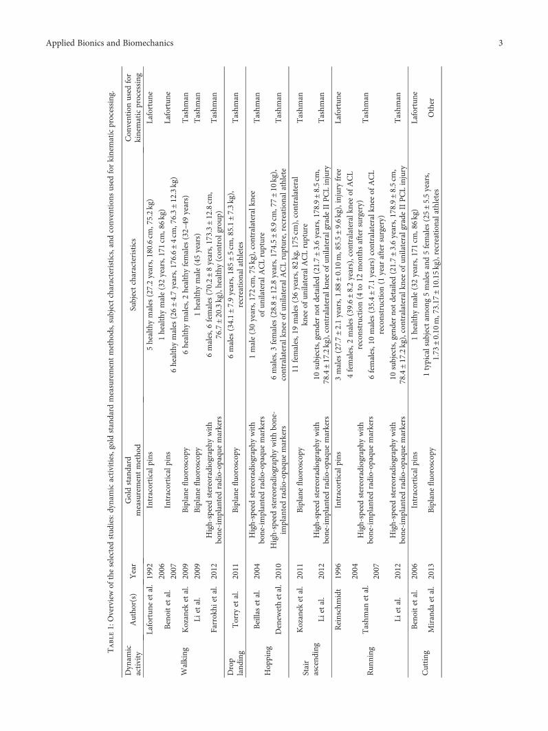
Table1:Overviewof
theselected
stud
ies:dynamicactivities,goldstandard
measurementmetho
ds,sub
jectcharacteristics,andconvention
sused
forkinematicprocessing.
Dynam
icactivity
Autho
r(s)
Year
Goldstandard
measurementmetho
dSubjectcharacteristics
Con
ventionused
for
kinematicprocessing
Walking
Lafortun
eetal.1992
Intracorticalp
ins
5healthymales
(27.2years,180.6cm
,75.2kg)
Lafortun
e
Benoitetal.
2006
Intracorticalp
ins
1healthymale(32years,171cm
,86kg)
Lafortun
e2007
6healthymales
(26±4.7years,176.6±4cm
,76.3±12.3kg)
Kozanek
etal.
2009
Biplane
fluo
roscop
y6healthymales,2
healthyfemales
(32–49
years)
Tashm
an
Lietal.
2009
Biplane
fluo
roscop
y1healthymale(45years)
Tashm
an
Farrokhi
etal.
2012
High-speedstereoradiograph
ywith
bone-implantedradio-op
aque
markers
6males,6
females
(70.2±8years,173.3±12.8cm
,76.7±20.3kg),healthy(con
trol
grou
p)Tashm
an
Drop
land
ing
Torry
etal.
2011
Biplane
fluo
roscop
y6males
(34.1±7.9years,185±5cm
,85.1±7.3kg),
recreation
alathletes
Tashm
an
Hop
ping
Beillasetal.
2004
High-speedstereoradiograph
ywith
bone-implantedradio-op
aque
markers
1male(30years,172cm
,75kg),contralateralk
nee
ofun
ilateralA
CLrupture
Tashm
an
Denew
ethetal.2010
High-speedstereoradiograph
ywithbone-
implantedradio-op
aque
markers
6males,3
females
(28.8±12.8years,174.5±8.9cm
,77±10
kg),
contralateralk
neeof
unilateralA
CLrupture,recreation
alathlete
Tashm
an
Stair
ascend
ing
Kozanek
etal.
2011
Biplane
fluo
roscop
y11
females,19males
(36years,82
kg,175
cm),contralateral
knee
ofun
ilateralA
CLrupture
Tashm
an
Lietal.
2012
High-speedstereoradiograph
ywith
bone-implantedradio-op
aque
markers
10subjects,genderno
tdetailed(21.7±3.6years,178.9±8.5cm
,78.4±17.2kg),contralateralk
neeof
unilateralgrade
IIPCLinjury
Tashm
an
Run
ning
Reinschmidt
1996
Intracorticalp
ins
3males
(27.7±2
.1years,1.88
±0.10
m,85.5±9.6kg),injury
free
Lafortun
e
Tashm
anetal.2004
High-speedstereoradiograph
ywith
bone-implantedradio-op
aque
markers
4females,2
males
(39.6±8.2years),con
tralateralkn
eeof
ACL
reconstruction
(4to
12mon
thsaftersurgery)
Tashm
an2007
6females,10males
(35.4±7.1years)contralateralk
neeof
ACL
reconstruction
(1year
aftersurgery)
Lietal.
2012
High-speedstereoradiograph
ywith
bone-implantedradio-op
aque
markers
10subjects,genderno
tdetailed(21.7±3.6years,178.9±8.5cm
,78.4±17.2kg),contralateralk
neeof
unilateralgrade
IIPCLinjury
Tashm
an
Cutting
Benoitetal.
2006
Intracorticalp
ins
1healthymale(32years,171cm
,86kg)
Lafortun
e
Miranda
etal.
2013
Biplane
fluo
roscop
y1typicalsub
jectam
ong5males
and5females
(25±5.5years,
1.73
±0.10
m,73.17
±10.15kg),recreation
alathletes
Other
3Applied Bionics and Biomechanics

Femur anatomical points:
LAF: long axis of femurL/MDC: lateral/medialmost distal point of condyle
FeH: femoral headL/MCC: lateral/medialcentre of condyle
L/ME: lateral/medialepicondyleMidpoint
Femur segment coordinate systems
LAF
LDC MDC
(a) (b) (c)
(d) (e) (f)
FeH FeH
MCCLCCMELE
ISBfy
ISBfx
ISBfz
Tfx
Tfy
Tfz
Lfy
Lfx
Lfz
Tibia segment coordinate systems
MTPLTP
CDT
FiH
MMLM
MCPLCP
LAT
ISBty
ISBtx
ISBtz
Ttx
Tty
Ttz
Lty
Ltx
Ltz
Tibia anatomical points:
LAT: long axis of tibiaL/MCP: lateral/medialcentre of tibia plateau
L/MTP: lateral/medial borders of tibial plateauCDT: centre of distal tibia
FiH: Fibula headL/MM: lateral/medialmalleolusMidpoint
Figure 2: Positions and orientations of the authors’ femur and tibia segment coordinate systems (SCS) with respect to the standardised SCSbased on the geometry of the Visible Human Project’s (VHP) knee: ((a), (d)) Lafortune’s convention, ((b), (e)) Tashman’s convention, and((c), (f)) International Society of Biomechanics standards.
4 Applied Bionics and Biomechanics

The 6 DoFs of the tibiofemoral joint were computed fromthe final transformation matrices TFISB→T ISB
, which take intoaccount the joint movement in the author’s convention, thechange in origin position and axis orientation from theauthors’ convention to the ISB standards, and the superimpo-sition of the tibia and femur at 0° of flexion. The transformedkinematics represents the movement of the tibia with respectto the femur. The knee joint angles were computed using thejoint coordinate system (JCS) equivalent to a ZXY Cardanicangle sequence [5]. The displacements of the tibia with respectto the femur were computed as the nonorthonormal projec-tion [25] of the vector from the femur origin to the tibia originon the axes of the JCS. The positive angles include extension,adduction, and internal rotation, and the positive displace-ments include lateral, anterior, and proximal. As extension-flexion is themainDoFof theknee, the 5otherDoFswere plot-ted against the flexion angle to present a synthesis of the kine-matic data.
2.3. Clustering Method. The synthesised kinematic data (i.e.,transformed within the ISB standard) were partitioned intosix clusters around medoids [26] with similarity amongclusters defined using a “cosine” distance (kmedoids.m inMatlab R2015a, The Mathworks). A medoid is defined asthe observation of the subset that is the closest to the meanobservation within the subset. The idea is to minimise thesum of the distances between each observation of the data’ssubset and the medoid of the subset. The iterative algorithm
returns a cluster index for each observation (as well ascluster’s medoid localisation and within-cluster point-to-medoid distances which were not analysed specifically). Inthe present case, the input data is formed of 17 (i.e., studies)times 100 (i.e., percentage of movement) rows and 6 (i.e.,DoFs) columns: X1700×6. The “cosine” distance between twoobservations (i.e., rows i and j) is given by
dij = 1−XiXT
j
XiXTj XiXT
j
2
The number of clusters, that is, 6, was specifically chosento test the effect of the activity on the 6-Dof kinematics.Indeed, one cluster by activity would eventually be foundif this effect was prevailing. Thus, the proportion of walk-ing, drop landing, hopping, stair ascending, running, andcutting in each cluster was computed. The proportion ofintracortical pins, biplane fluoroscopy, and high-speedstereoradiography was also computed to test the effect ofthe measurement method.
2.4. Evaluation of the Transformation. The influence of thetransformation of the kinematic data into the ISB standardson the DoF patterns was evaluated with the R2 and RMSDbetween the kinematic curves obtained with the transformed(i.e., TFISB→TISB
) dataset and the original dataset corrected forsign convention (i.e., Tc
FA→TA, see Figure 1) to avoid large
−80 −60 −40 −20 0
−10
0
10
20
30
Disp
lace
men
t (m
m)
Extension (+)/flexion (−) (degree)
Lateral (+)/medial (−)
−80 −60 −40 −20 0
−10
0
10
20
30
Extension (+)/flexion (−) (degree)
Anterior (+)/posterior (−)
−80 −60 −40 −20 0
−10
0
10
20
30Proximal (+)/distal (−)
Extension (+)/flexion (−) (degree)
WalkingDrop landingHopping
Stair ascendingRunningCutting
WalkingDrop landingHopping
Stair ascendingRunningCutting
WalkingDrop landingHopping
Stair ascendingRunningCutting
−80 −60 −40 −20 0
−10
0
10
20Adduction (+)/abduction (−)
Ang
le (d
egre
e)
−80 −60 −40 −20 0−10
0
10
20Internal (+)/external (−) rotation
Figure 3: Synthesised tibiofemoral joint angles and displacements during walking, drop landing, hopping, stair ascending, running,and cutting.
5Applied Bionics and Biomechanics

deviations due to differences in axis orientation. As anexample, the lateral direction is positive in ISB standardsand negative in Tashman’s convention.
3. Results
The synthesised data are all available in SupplementaryMate-rial (synthetised knee kinematic data during weight bearingactivities) available online at https://doi.org/10.1155/2017/1908618. Figure 3 displays the curves of all 17 studies withdifferent colours for each dynamic activity. The range oftibiofemoral extension-flexion was from +4° to −61°. Duringtibiofemoral flexion, the motion of the tibia relative to thefemur was mainly in abduction, internal rotation, andmedial, anterior, and proximal displacement. The range ofadduction-abduction (AA) was from +1° to −11°. Most ofthe abduction versus flexion patterns were almost straightlines. The range of the internal-external rotation (IER) wasfrom −1° to +15°. Some internal rotation versus flexionpatterns were S-shaped and revealed some differencesaccording to the movement toward flexion or extension.The range of lateral-medial displacement (LM) was from+5mm to −9mm. The medial displacement versus flexionpatterns were mainly concave curves, with a medial displace-ment increasing for flexion from approximately 0° to −20°and decreasing for flexion from −20° to −60°. The range ofanterior-posterior displacement (AP) was from −2mm to+26mm. The anterior displacement versus flexion patternswere mainly convex curves, with an anterior displacementhighly increasing for flexion from approximately 0° to −30°and a reduced increase from −30° to −60°. The range ofproximal-distal displacement (PD) was from −3mm to+28mm. The proximal displacement versus flexion patternswere mainly concave curves, with a proximal displacementslightly increasing for flexion from approximately 0° to−20° and highly increasing from −20° to −60°.
The k-medoid procedure resulted in partitioning thedata into six clusters (Figure 4) that were not associated toa particular dynamic activity or measurement methodexcept for cluster number 3 (high-speed stereoradiography),number 4 (walking and biplane fluoroscopy), and number6 (biplane fluoroscopy). The repartition of the wholedataset into the cluster numbers 1 to 6 was 39%, 34%,18%, 4%, 3%, and 2%, respectively. The curves of all 17studies with different colours for each cluster are providedas Supplementary Material (Figure S1: repartition of thesynthetised knee kinematic data among each cluster).
Concerning the evaluation of the effect of the transforma-tion of the kinematic data into the ISB standards, the medianR2 (Figure 5) was above 0.9 for the AA, IER, and PDtransformed from the studies using Lafortune’s conventionand for the IER, LM, and AP transformed from the studiesusing Tashman’s convention. It was above 0.6 for the LMtransformed from the studies using Lafortune’s conventionand for the AA and PD transformed from the studies usingTashman’s convention. The median R2 was 0.07 for the APtransformed from the studies using Lafortune’s convention.
The median RMSD (Figure 6) was below 5° for the FEand AA and below 5mm for the LM transformed from the
studies using Lafortune’s convention. For the IER, AP,and PD, the median RMSD was below 10° and 10mm.For the kinematic data transformed from the studies usingTashman’s convention, the median RMSD was below 5°
and 5mm except for the PD which reached 23mm.
4. Discussion
In this paper, data from various studies were transformedinto the ISB standards [5] to build a homogeneous database
0
20
40
Perc
enta
ge
Repartition of data points in clusters
Cluster #1Cluster #2Cluster #3
Cluster #4Cluster #5Cluster #6
#1 #2 #3 #4 #5 #6
#1 #2 #3 #4 #5 #6
0
50
100
Perc
enta
ge
Proportion of each dynamicactivity in each cluster
WalkingDrop landingHopping
Stair ascendingRunningCutting
#1 #2 #3 #4 #5 #60
50
100
Cluster
Cluster
Cluster
Perc
enta
ge
Proportion of each measurementmethod in each cluster
Intracortical pinsBiplane fluoroscopyStereoradiography
Figure 4: Partition of the synthesised kinematic data intosix clusters.
6 Applied Bionics and Biomechanics

of comparable motion and to identify patterns of in vivotibiofemoral kinematics. The synthesised kinematic datarevealed a behaviour that was consistent with the classicalfunctional description of the knee [27–30] which wasmainly based on the articular surface and ligament evi-dences and on in vitro measurements. For instance, theabduction angle (up to −11°) did not demonstrate anydecoaptation of the joint, but the difference between themedial and lateral radii of curvature of the femoral con-dyles and tibial plateaus [29, 31]. Similarly, the proximaldisplacement (up to 28mm) did not demonstrate anycompression of the femur on the tibia but a variation ofthe radius of curvature of the femoral condyles and tibial
plateaus in the sagittal plane [29, 31]. The literature sug-gested that normal in vivo kinematics was different fromin vitro ones, and varied with dynamic activities, especiallyfor internal-external rotation and anterior-posterior dis-placement [32–34]. In the present study, three quartersof the synthesised kinematic data were included in twomain clusters featuring all dynamic activities. Thus, theeffect of the dynamic activities on the couplings betweenthe tibiofemoral DoFs appeared limited. S-shaped patternsin the internal rotation curves were observed in studiesusing intracortical pins [1, 7, 8] and biplane fluoroscopy[10, 18], but not for studies with high-speed stereoradio-graphy [3, 9, 12, 13, 17]. Moreover, the last quarter of
0
0.2
0.4
0.6
0.8
1
FE AA IER LM AP PD
Tashman’s convention
R2
0
0.2
0.4
0.6
0.8
1
FE AA IER LM AP PD
Lafortune’s convention
R2
Figure 5: Determination coefficient between the data in the convention of Lafortune and Tashman and the data transformed into theInternational Society of Biomechanics standards.
0
5
10
15
20
25
30
35Tashman’s convention
RMSD
(deg) (deg) (deg) (mm) (mm) (mm)
0
5
10
15
20
25
30
35
FE AA IER LM AP PDFE AA IER LM AP PD
Lafortune’s convention
RMSD
(deg) (deg) (deg) (mm) (mm) (mm)
Figure 6: Root mean square difference between the data in the convention of Lafortune and Tashman and the data transformed into theInternational Society of Biomechanics standards.
7Applied Bionics and Biomechanics

the data was partitioned according to the measurementmethods (cluster numbers 3, 4, and 6). Thus, it appearedthat the measurement method might yield, in some cases,specific kinematic patterns.
The present study has several limitations. First, the orig-inal data correspond to mean curves that do not represent thekinematics of a specific subject [35]. In addition, all thecurves were digitised from published graphs. However, thisrepresents currently the only data available in the literature.Second, since they did not exhibit any pathology, the kneejoints were assumed normal although some of them werebelonging to athletes, seniors, and subjects with contralateraldisorders (Table 1). Third, the reprocessing of kinematics(i.e., positions and orientations of the authors’ femur andtibia SCS with respect to the standardised SCS) was basedon a single cadaveric knee geometry. The bias introducedby this approximation in the geometry cannot be assessedbecause the geometry of the subjects from the various studiesis unknown. However, the variability due to this geometricalapproximation should be reduced by the superimposition ofthe femur and tibia SCS at 0° of flexion [23]. This superimpo-sition is classic when looking at couplings between the DoFsand was previously performed by some authors of theselected studies with superimposition of the origin [9, 11, 13]or without [1, 7, 8]. As an attempt to estimate the variabilitydue to the unknown differences in geometry, the RMSDbetween the transformed and original data were computedand analysed. The median RMSD was generally below 5°
and 10mm. It is expected that the effect of different geome-tries is largely inferior to the effect of different segment axesand origin conventions.
As a conclusion, the synthesised kinematic data provide alarge sample of couplings between the tibiofemoral DoFsbased on 17 studies averaging 126 subjects. The main partof the data was consistent among the different activities (i.e.,walking, drop landing, hopping, stair ascending, running,and cutting) and measurement methods (i.e., intracorticalpins, biplane fluoroscopy, and high-speed stereoradiogra-phy). Moderate to good correlations between the transformedand original data indicated that the patterns of the couplingsbetween the DoFs observed in this study remained generallyconsistent with the original data. It can be expected thatkinematics of normal knee measured with gold standardmeasurement methods become available as open data inthe next future. Meanwhile, the kinematic data synthesisedin the present study might be used as a reference of normalin vivo knee kinematics for prosthetic and orthotic designand for the development and validation of biomechanicalknee models.
Appendix
The keywords used for database queries (Pubmed, Scopus,and Web of Knowledge) were biplan∗ fluoroscop∗ OR dualfluoroscop∗ stereo X-ray OR stereo∗radiograph∗ OR biplan∗
radiograph∗ OR pins AND knee OR tibio∗femoral ANDkinematic∗ AND gait OR walking OR running OR stair ORstep OR cut∗ OR jump OR hop∗ OR drop. From the obtained
references, the selected papers were those displaying all of the6 DoFs of normal tibiofemoral joint.
Conflicts of Interest
The authors declare that there is no conflict of interestregarding the publication of this paper.
Acknowledgments
This work was performed within the framework of theLABEX PRIMES (ANR-11-LABX-0063) of Université deLyon, within the program “Investissements d’Avenir”(ANR-11-IDEX-0007) operated by the French NationalResearch Agency (ANR).
References
[1] M. A. Lafortune, P. R. Cavanagh,H. J. Sommer, andA.Kalenak,“Three-dimensional kinematics of the human knee duringwalking,” Journal of Biomechanics, vol. 25, no. 4, pp. 347–357, 1992.
[2] M.Kozanek, A.Hosseini, F. Liu et al., “Tibiofemoral kinematicsand condylar motion during the stance phase of gait,” Journalof Biomechanics, vol. 42, no. 12, pp. 1877–1884, 2009.
[3] S. Tashman, D. Collon, K. Anderson, P. Kolowich, andW. Anderst, “Abnormal rotational knee motion during run-ning after anterior cruciate ligament reconstruction,”AmericanJournal of Sports Medicine, vol. 32, no. 4, pp. 975–983, 2004.
[4] E. S. Grood and W. J. Suntay, “A joint coordinate system forthe clinical description of three-dimensional motions: applica-tion to the knee,” Journal of Biomechanical Engineering,vol. 105, no. 2, pp. 136–144, 1983.
[5] G. Wu and P. R. Cavanagh, “ISB recommendations in thereporting for standardization of kinematic data,” Journal ofBiomechanics, vol. 28, no. 10, pp. 1257–1261, 1995.
[6] D. Moher, A. Liberati, J. Tetzlaff, D. G. Altman, and PRISMAGroup, “Preferred reporting items for systematic reviews andmeta-analyses: the PRISMA statement,” PLoS Medicine,vol. 6, no. 7, article e1000097, 2009.
[7] D. L. Benoit, D. K. Ramsey, M. Lamontagne, L. Xu,P. Wretenberg, and P. Renström, “Effect of skin movementartifact on knee kinematics during gait and cutting motionsmeasured in vivo,” Gait & Posture, vol. 24, no. 2, pp. 152–164, 2006.
[8] D. L. Benoit, D. K. Ramsey, M. A. Lamontagne, L. Xu,P. Wretenberg, and P. Renström, “In vivo knee kinematicsduring gait reveals new rotation profiles and smaller transla-tions,” Clinical Orthopaedics and Related Research, vol. 454,pp. 81–88, 2007.
[9] S. Farrokhi, S. Tashman, A. B. Gil, B. A. Klatt, and G. K.Fitzgerald, “Are the kinematics of the knee joint alteredduring the loading response phase of gait in individuals withconcurrent knee osteoarthritis and complaints of joint insta-bility? A dynamic stereo X-ray study,” Clinical biomechanics,vol. 27, no. 4, pp. 384–389, 2012.
[10] G. Li, M. Kozanek, A. Hosseini, F. Liu, S. K. Van de Velde,and H. E. Rubash, “New fluoroscopic imaging technique forinvestigation of 6DOF knee kinematics during treadmillgait,” Journal of Orthopaedic Surgery and Research, vol. 4,no. 1, pp. 1–5, 2009.
8 Applied Bionics and Biomechanics

[11] M. R. Torry, K. B. Shelburne, D. S. Peterson et al., “Kneekinematic profiles during drop landings: a biplane fluoroscopystudy,” Medicine and Science in Sports and Exercise, vol. 43,no. 3, pp. 533–541, 2011.
[12] P. Beillas, G. Papaioannou, S. Tashman, and K. H. Yang, “Anew method to investigate in vivo knee behavior using a finiteelement model of the lower limb,” Journal of Biomechanics,vol. 37, no. 7, pp. 1019–1030, 2004.
[13] J. M. Deneweth, M. J. Bey, S. G. McLean, T. R. Lock, P. A.Kolowich, and S. Tashman, “Tibiofemoral joint kinematics ofthe anterior cruciate ligament-reconstructed knee during asingle-legged hop landing,” The American Journal of SportsMedicine, vol. 38, no. 9, pp. 1820–1828, 2010.
[14] M. Kozanek, A. Hosseini, S. K. V. de Velde et al., “Kinematicevaluation of the step-up exercise in anterior cruciateligament deficiency,” Clinical biomechanics, vol. 26, no. 9,pp. 950–954, 2011.
[15] K. Li, L. Zheng, S. Tashman, and X. Zhang, “The inaccuracyof surface-measured model-derived tibiofemoral kinematics,”Journal of Biomechanics, vol. 45, no. 15, pp. 2719–2723,2012.
[16] C. Reinschmidt, Three-dimensional tibiocalcaneal and tibio-femoral kinematics during human locomotion - measuredwith external and bone markers, Ph.D. thesis, University ofCalgary, 1996.
[17] S. Tashman, P. Kolowich, D. Collon, K. Anderson, andW. Anderst, “Dynamic function of the ACL-reconstructedknee during running,” Clinical Orthopaedics and RelatedResearch, vol. 454, pp. 66–73, 2007.
[18] D. L. Miranda, M. J. Rainbow, J. J. Crisco, and B. C. Fleming,“Kinematic differences between optical motion capture andbiplanar videoradiography during a jump–cut maneuver,”Journal of Biomechanics, vol. 46, no. 3, pp. 1–8, 2013.
[19] S. Tashman and W. Anderst, “In-vivo measurement ofdynamic joint motion using high speed biplane radiographyand CT: application to canine ACL deficiency,” Journal ofBiomechanical Engineering, vol. 125, no. 2, pp. 238–245, 2003.
[20] M. J. Ackerman, “The visible human project,” Journal ofBiocommunication, vol. 18, no. 2, 14 pages, 1991.
[21] R. M. A. Al-Dirini, D. Thewlis, and G. Paul, “A comprehensiveliterature review of the pelvis and the lower extremity FEhuman models under quasi-static conditions,” Work, vol. 41,Supplement 1, pp. 4218–4229, 2012.
[22] M. Viceconti, D. Testi, F. Taddei, S. Martelli, G. J. Clapworthy,and S. V. S. Jan, “Biomechanics modeling of the musculoskel-etal apparatus: status and key issues,” Proceedings of the IEEE,vol. 94, no. 4, pp. 725–739, 2006.
[23] J. L. Lewis and W. D. Lew, “A note on the description ofarticulating joint motion,” Journal of Biomechanics, vol. 10,no. 10, pp. 675–678, 1977.
[24] B. Michaud, M. I. Jackson, F. Prince, and M. S. Begon, “Canone angle be simply subtracted from another to determinerange of motion in three-dimensional motion analysis?” Com-puter Methods in Biomechanics and Biomedical Engineering,vol. 17, no. 5, pp. 507–515, 2014.
[25] G. Desroches, L. Cheze, and R. Dumas, “Expression of jointmoment in the joint coordinate system,” Journal of Biome-chanical Engineering, vol. 132, no. 11, article 114503, 2010.
[26] L. Kaufman andP. J. Rousseeuw, “Partitioning aroundmedoids(programPAM),” inFindingGroups inData: an Introduction to
Cluster Analysis, L. Kaufman and P. J. Rousseeuw, Eds., pp. 68–125, JohnWiley & Sons, Inc., 1990.
[27] R. Cailliet, “Knee pain and disability,” Medicine & Science inSports & Exercise, vol. 24, no. 10, 1182 pages, 1992.
[28] M. R. Freeman and V. Pinskerova, “The movement of thenormal tibio-femoral joint,” Journal of Biomechanics, vol. 38,no. 2, pp. 197–208, 2005.
[29] I. A. Kapandji, The physiology of the joints, Churchill Living-stone, London, 2010.
[30] P. N. Smith, K. M. Refshauge, and J. M. Scarvell, “Develop-ment of the concepts of knee kinematics,” Archives of PhysicalMedicine and Rehabilitation, vol. 84, no. 12, pp. 1895–1902,2003.
[31] S. Martelli and V. Pinskerova, “The shapes of the tibial andfemoral articular surfaces in relation to tibiofemoral move-ment,” Journal of Bone & Joint Surgery (Br), vol. 84, no. 4,pp. 607–613, 2002.
[32] T. A. Moro-oka, S. Hamai, H. Miura et al., “Dynamic activitydependence of in vivo normal knee kinematics,” Journal ofOrthopaedic Research, vol. 26, no. 4, pp. 428–434, 2008.
[33] C. A. Myers, M. R. Torry, K. B. Shelburne et al., “In vivo tibio-femoral kinematics during 4 functional tasks of increasingdemand using biplane fluoroscopy,” The American Journal ofSports Medicine, vol. 40, no. 1, pp. 170–178, 2012.
[34] C. J. Westphal, A. Schmitz, S. B. Reeder, and D. G. Thelen,“Load-dependent variations in knee kinematics measured withdynamic MRI,” Journal of Biomechanics, vol. 46, no. 12,pp. 2045–2052, 2013.
[35] D. D. Cook and D. J. Robertson, “The generic modeling fallacy:average biomechanical models often produce non-averageresults!,” Journal of Biomechanics, vol. 49, no. 15, pp. 3609–3615, 2016.
9Applied Bionics and Biomechanics

RoboticsJournal of
Hindawi Publishing Corporationhttp://www.hindawi.com Volume 2014
Hindawi Publishing Corporationhttp://www.hindawi.com Volume 2014
Active and Passive Electronic Components
Control Scienceand Engineering
Journal of
Hindawi Publishing Corporationhttp://www.hindawi.com Volume 2014
International Journal of
RotatingMachinery
Hindawi Publishing Corporationhttp://www.hindawi.com Volume 2014
Hindawi Publishing Corporation http://www.hindawi.com
Journal of
Volume 201
Submit your manuscripts athttps://www.hindawi.com
VLSI Design
Hindawi Publishing Corporationhttp://www.hindawi.com Volume 201
Hindawi Publishing Corporationhttp://www.hindawi.com Volume 2014
Shock and Vibration
Hindawi Publishing Corporationhttp://www.hindawi.com Volume 2014
Civil EngineeringAdvances in
Acoustics and VibrationAdvances in
Hindawi Publishing Corporationhttp://www.hindawi.com Volume 2014
Hindawi Publishing Corporationhttp://www.hindawi.com Volume 2014
Electrical and Computer Engineering
Journal of
Advances inOptoElectronics
Hindawi Publishing Corporation http://www.hindawi.com
Volume 2014
The Scientific World JournalHindawi Publishing Corporation http://www.hindawi.com Volume 2014
SensorsJournal of
Hindawi Publishing Corporationhttp://www.hindawi.com Volume 2014
Modelling & Simulation in EngineeringHindawi Publishing Corporation http://www.hindawi.com Volume 2014
Hindawi Publishing Corporationhttp://www.hindawi.com Volume 2014
Chemical EngineeringInternational Journal of Antennas and
Propagation
International Journal of
Hindawi Publishing Corporationhttp://www.hindawi.com Volume 2014
Hindawi Publishing Corporationhttp://www.hindawi.com Volume 2014
Navigation and Observation
International Journal of
Hindawi Publishing Corporationhttp://www.hindawi.com Volume 2014
DistributedSensor Networks
International Journal of