Embed Size (px)
Citation preview
F-22-100July 2016
Spark Electrodes/Flame Sensors
For Gas Ignition Systems
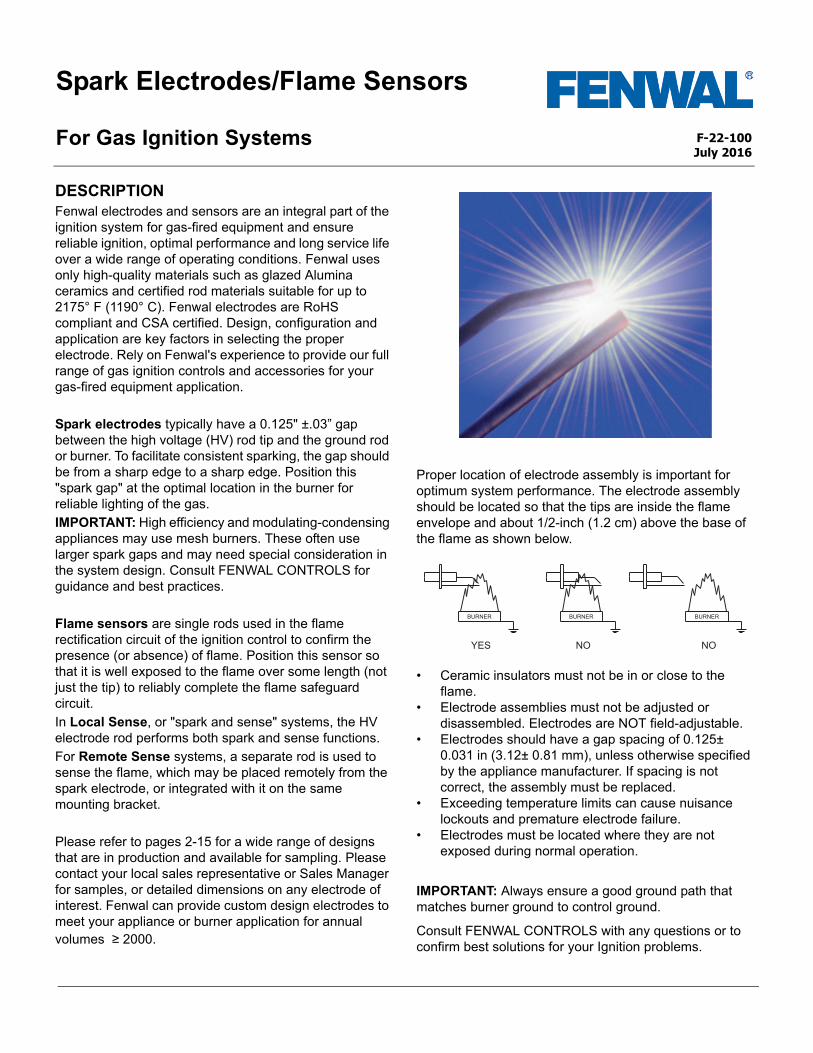
DESCRIPTIONFenwal electrodes and sensors are an integral part of the ignition system for gas-fired equipment and ensure reliable ignition, optimal performance and long service life over a wide range of operating conditions. Fenwal uses only high-quality materials such as glazed Alumina ceramics and certified rod materials suitable for up to 2175° F (1190° C). Fenwal electrodes are RoHS compliant and CSA certified. Design, configuration and application are key factors in selecting the proper electrode. Rely on Fenwal's experience to provide our full range of gas ignition controls and accessories for your gas-fired equipment application.
Spark electrodes typically have a 0.125" ±.03” gap between the high voltage (HV) rod tip and the ground rod or burner. To facilitate consistent sparking, the gap should be from a sharp edge to a sharp edge. Position this "spark gap" at the optimal location in the burner for reliable lighting of the gas.
IMPORTANT: High efficiency and modulating-condensing appliances may use mesh burners. These often use larger spark gaps and may need special consideration in the system design. Consult FENWAL CONTROLS for guidance and best practices.
Flame sensors are single rods used in the flame rectification circuit of the ignition control to confirm the presence (or absence) of flame. Position this sensor so that it is well exposed to the flame over some length (not just the tip) to reliably complete the flame safeguard circuit.
In Local Sense, or "spark and sense" systems, the HV electrode rod performs both spark and sense functions.
For Remote Sense systems, a separate rod is used to sense the flame, which may be placed remotely from the spark electrode, or integrated with it on the same mounting bracket.
Please refer to pages 2-15 for a wide range of designs that are in production and available for sampling. Please contact your local sales representative or Sales Manager for samples, or detailed dimensions on any electrode of interest. Fenwal can provide custom design electrodes to meet your appliance or burner application for annual volumes ≥ 2000.
Proper location of electrode assembly is important for optimum system performance. The electrode assembly should be located so that the tips are inside the flame envelope and about 1/2-inch (1.2 cm) above the base of the flame as shown below.
• Ceramic insulators must not be in or close to the flame.
• Electrode assemblies must not be adjusted or disassembled. Electrodes are NOT field-adjustable.
• Electrodes should have a gap spacing of 0.125± 0.031 in (3.12± 0.81 mm), unless otherwise specified by the appliance manufacturer. If spacing is not correct, the assembly must be replaced.
• Exceeding temperature limits can cause nuisance lockouts and premature electrode failure.
• Electrodes must be located where they are not exposed during normal operation.
IMPORTANT: Always ensure a good ground path thatmatches burner ground to control ground.
Consult FENWAL CONTROLS with any questions or to confirm best solutions for your Ignition problems.
Note: Illustrations are not to scale.
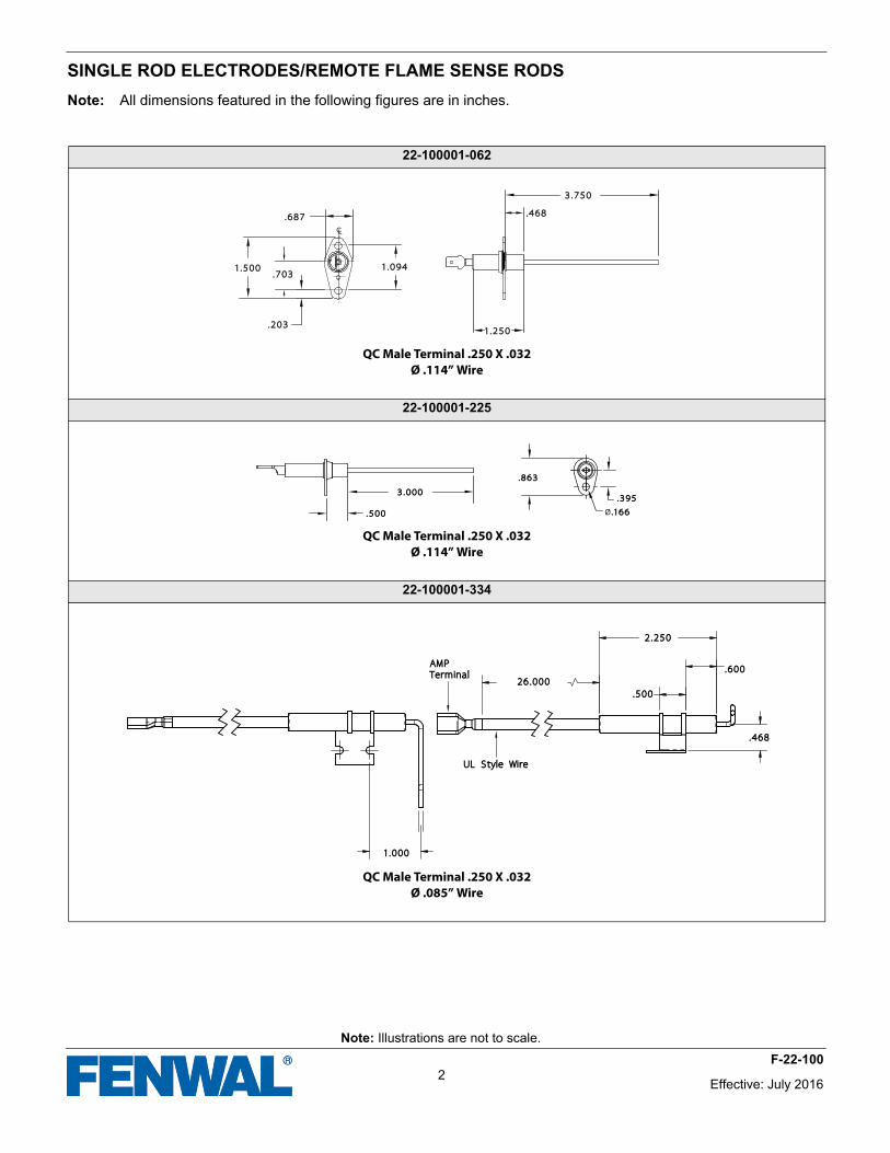
SINGLE ROD ELECTRODES/REMOTE FLAME SENSE RODS
Note: All dimensions featured in the following figures are in inches.
22-100001-062
QC Male Terminal .250 X .032Ø .114” Wire
22-100001-225
QC Male Terminal .250 X .032Ø .114” Wire
22-100001-334
QC Male Terminal .250 X .032Ø .085” Wire
CL
3.7503.750
.468.468.687.687
.703.703
.203.203
1.0941.0941.5001.500
1.2501.250
.395.395
.500.500
3.0003.000
.863.863
Ø.166.166
2.2502.250
.600.600
.500.500
.468.468
26.00026.000
1.0001.000
UL Style WireUL Style Wire
AMP AMP TerminalTerminal
Effective: July 20162
F-22-100
Note: Illustrations are not to scale.
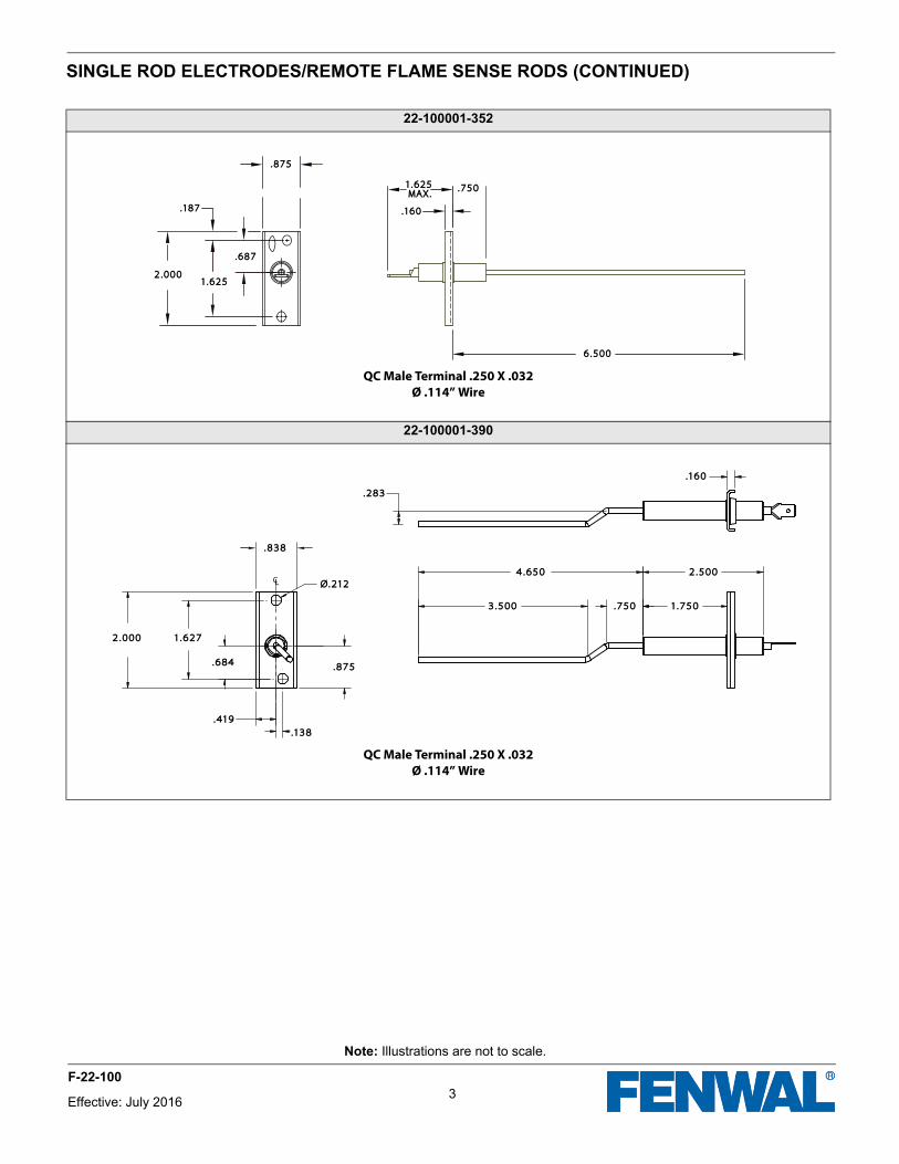
SINGLE ROD ELECTRODES/REMOTE FLAME SENSE RODS (CONTINUED)
22-100001-352
QC Male Terminal .250 X .032Ø .114” Wire
22-100001-390
QC Male Terminal .250 X .032Ø .114” Wire
MAX.MAX.
.875.875
.187.187
1.6251.625
.687.687
.750.750
.160.160
1.6251.625
6.5006.500
2.0002.000
CL
.838.838
Ø.212Ø.212
2.0002.000 1.6271.627
.684.684 .875.875
.419.419
.138.138
3.5003.500
4.6504.650
.750.750 1.7501.750
2.5002.500
.160.160
.283.283
3Effective: July 2016
F-22-100
Note: Illustrations are not to scale.
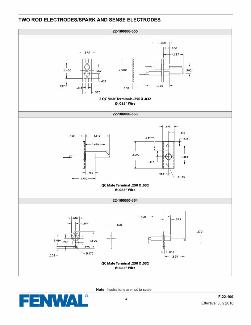
TWO ROD ELECTRODES/SPARK AND SENSE ELECTRODES
22-100000-555
2 QC Male Terminals .250 X .032Ø .085” Wire
22-100000-663
QC Male Terminal .250 X .032Ø .085” Wire
22-100000-664
QC Male Terminal .250 X .032Ø .085” Wire
.375.375
.218.218.297.297
1.4061.406
.421.421
.562.562
.875.875
.160.160
2.0002.000
1.7501.750
.562.562
1.2501.250
.500.500
1.6871.687
.364.364
.875.875
2.0002.000
.437.437
.062.062
.173.173
1.3501.350
.325.325
.438.438
.750.750
1.7501.750
.160.160
1.4891.489
1.8121.812
.687.687
.344.344.160.160
1.5001.500
.375.375
Ø.172Ø.172
.703.7031.0941.094
.203.203
1.7501.750
.031.031
1.8291.829
.270.270
.577.577
Effective: July 20164
F-22-100
Note: Illustrations are not to scale.
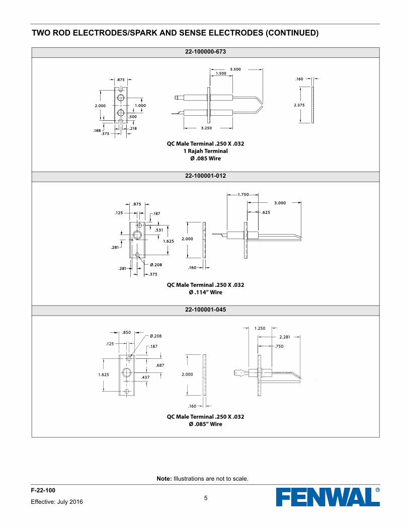
TWO ROD ELECTRODES/SPARK AND SENSE ELECTRODES (CONTINUED)
22-100000-673
QC Male Terminal .250 X .0321 Rajah Terminal
Ø .085 Wire
22-100001-012
QC Male Terminal .250 X .032Ø .114” Wire
22-100001-045
QC Male Terminal .250 X .032Ø .085” Wire
.160.160
2.3752.375
3.2503.250
3.5003.5001.5001.500
1.0001.000
.500.500
.218.218
.375.375.188.188
2.0002.000
.875.875
.875.875
.187.187.125.125
.531.531
2.0002.000
.160.160
.375.375
.281.281
.281.281
1.6251.625
Ø.208Ø.208
1.7501.750
3.0003.000
.625.625
.850.850
.125.125
1.6251.625
.160.160
2.0002.000
.187.187
.687.687
.437.437
Ø.208Ø.208
1.2501.250
2.2812.281
.750.750
5Effective: July 2016
F-22-100
Note: Illustrations are not to scale.
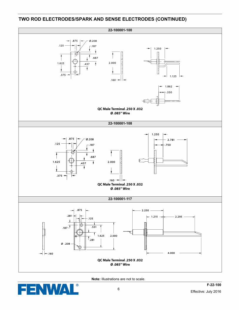
TWO ROD ELECTRODES/SPARK AND SENSE ELECTRODES (CONTINUED)
22-100001-100
QC Male Terminal .250 X .032Ø .085” Wire
22-100001-108
QC Male Terminal .250 X .032Ø .085” Wire
22-100001-117
QC Male Terminal .250 X .032Ø .085” Wire
.875.875
.125.125
1.6251.625
.375.375
.437.437
.687.687
.187.187
Ø.208Ø.208
2.0002.000
.160.160
1.1251.125
1.2501.250
1.8621.862
.550.550
.875.875
.125.125 .187.187
.687.687
.437.437
.375.375
1.6251.625 2.0002.000
.160.160
Ø.208Ø.208
.750.750
2.7812.781
1.2501.250
2.2502.250
1.2151.215 2.2952.295
4.0004.000
2.0002.0001.6251.625
.531.531
.125.125
.875.875
.281.281
.187.187
.160.160
Ø .208Ø .208
.281.281
Effective: July 20166
F-22-100
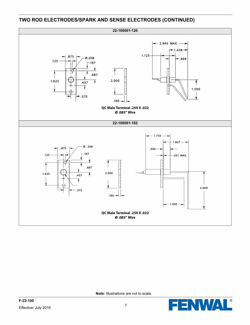
TWO ROD ELECTRODES/SPARK AND SENSE ELECTRODES (CONTINUED)
22-100001-120
QC Male Terminal .250 X .032Ø .085” Wire
22-100001-182
QC Male Terminal .250 X .032Ø .085” Wire
1.1251.125
1.5001.500
.468.468
1.4381.438
2.845 MAX.2.845 MAX.
2.0002.000
.160.160
.687.687
.437.437
.375.375
1.6251.625
.125.125
.875.875 Ø.208Ø.208
.187.187
.031 MAX..031 MAX.
1.8271.827
1.7501.750
.500.500
1.5001.500
2.6692.669
2.0002.000
.160.160
.375.375
.125.125
1.6251.625
.187.187
.687.687
.875.875
.437.437
Ø .208Ø .208
7
Note: Illustrations are not to scale.
Effective: July 2016
F-22-100
Note: Illustrations are not to scale.
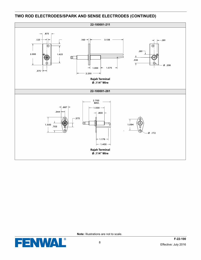
TWO ROD ELECTRODES/SPARK AND SENSE ELECTRODES (CONTINUED)
22-100001-211
Rajah TerminalØ .114” Wire
22-100001-261
Rajah TerminalØ .114” Wire
.875.875
2.0002.000
.375.375
2.2502.250
1.0001.000 1.5751.575
.160.160 3.1383.138
1.6251.625
.125.125
.530.530
.281.281
.281.281
Ø .208Ø .208
.687.687
1.5001.500
.375.375
.344.344
.703.703
.800.800
1.5001.500
2.700 2.700 MAX.MAX.
1.1761.176
1.4001.400
1.0941.094
Ø .172Ø .172
Effective: July 20168
F-22-100
Note: Illustrations are not to scale.
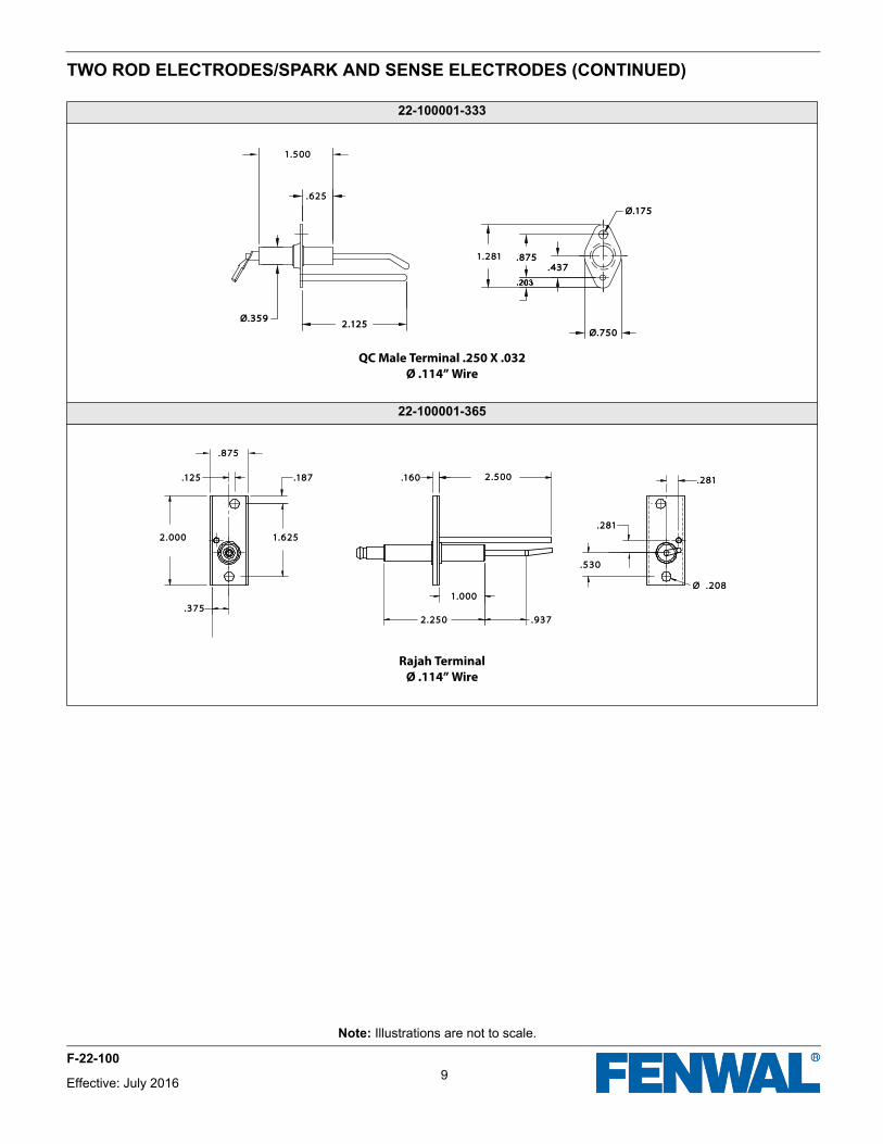
TWO ROD ELECTRODES/SPARK AND SENSE ELECTRODES (CONTINUED)
22-100001-333
QC Male Terminal .250 X .032Ø .114” Wire
22-100001-365
Rajah TerminalØ .114” Wire
2.1252.125
.875.875
1.5001.500
.625.625
1.2811.281.437.437
Ø.750Ø.750
Ø.175Ø.175
Ø.359Ø.359
.937.937
1.0001.000
2.2502.250
.375.375
1.6251.625
2.5002.500.160.160.187.187.125.125
.875.875
2.0002.000
Ø .208Ø .208
.530.530
.281.281
.281.281
9Effective: July 2016
F-22-100
Note: Illustrations are not to scale.
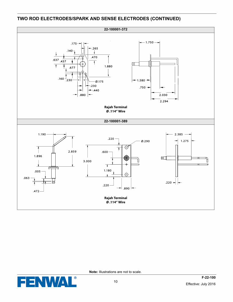
TWO ROD ELECTRODES/SPARK AND SENSE ELECTRODES (CONTINUED)
22-100001-372
Rajah TerminalØ .114” Wire
22-100001-389
Rajah TerminalØ .114” Wire
.175.175
.140.140
.637.637.437.437
.677.677
.160.160.230.230
.440.440
.
.880.880
1.8801.880
Ø.175Ø.175
.470.470
.265.265
1.7501.750
1.5801.580
.750.750
2.2942.294
2.0302.030
.230.230
1.1901.190
1.8961.896
.005.005
.063.063
.472.472
2.8592.859
3.0003.000
.220.220
1.1801.180
.600.600
.220.220
.890.890
Ø.290Ø.290
.220.220
1.2751.275
2.3852.385
Effective: July 201610
F-22-100
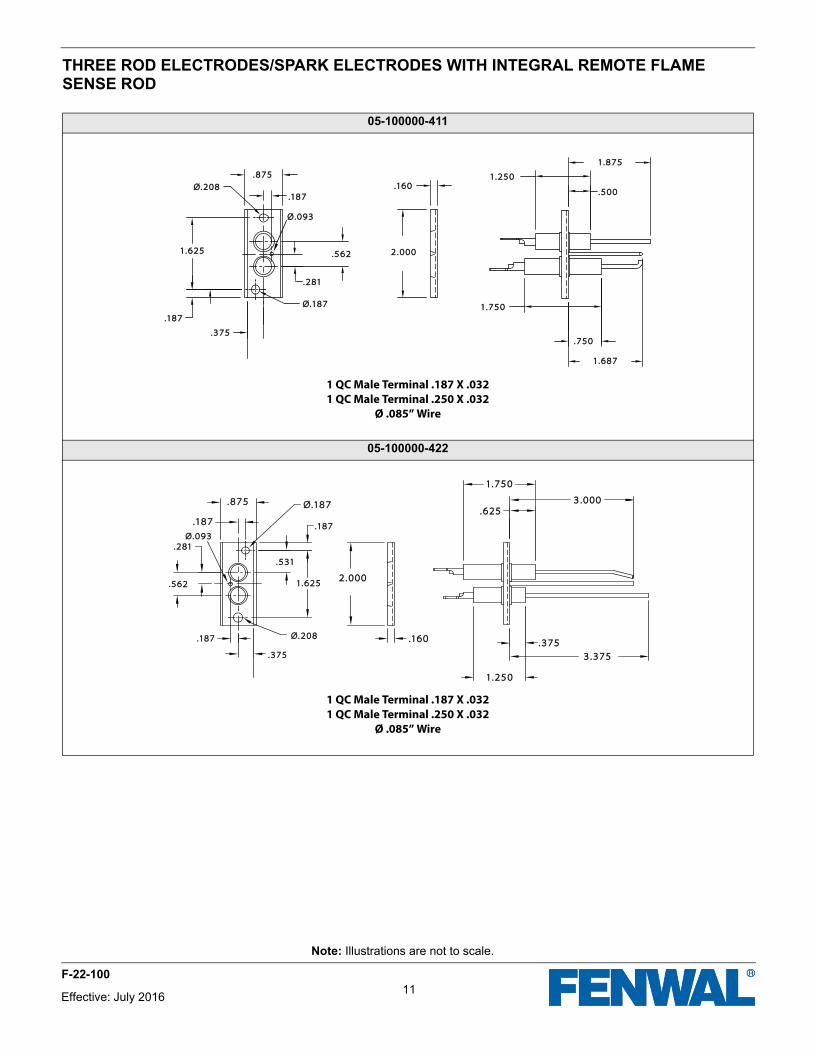
THREE ROD ELECTRODES/SPARK ELECTRODES WITH INTEGRAL REMOTE FLAME SENSE ROD
05-100000-411
1 QC Male Terminal .187 X .0321 QC Male Terminal .250 X .032
Ø .085” Wire
05-100000-422
1 QC Male Terminal .187 X .0321 QC Male Terminal .250 X .032
Ø .085” Wire
1.6871.687
.750.750
1.7501.750
.160.160.500.500
1.2501.250
1.8751.875
2.0002.000.562.562
Ø.187Ø.187
.375.375
.187.187
1.6251.625
.187.187Ø.208Ø.208
Ø.093Ø.093
.281.281
.875.875
.187.187.187.187
.531.531
1.6251.625
.281.281
.562.5622.0002.000
.187.187
.375.375
.160.160
.625.6253.0003.000
.375.375
3.3753.375
1.2501.250
1.7501.750
Ø.093Ø.093
Ø.187Ø.187
Ø.208Ø.208
.875.875
11
Note: Illustrations are not to scale.
Effective: July 2016
F-22-100
Note: Illustrations are not to scale.
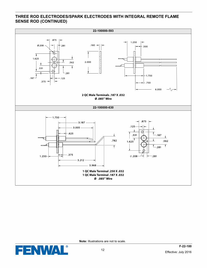
THREE ROD ELECTRODES/SPARK ELECTRODES WITH INTEGRAL REMOTE FLAME SENSE ROD (CONTINUED)
22-100000-593
2 QC Male Terminals .187 X .032Ø .085” Wire
22-100000-630
1 QC Male Terminal .250 X .0321 QC Male Terminal .187 X .032
Ø .085” Wire
6.0006.000
.750.750
1.7501.750
.500.500
1.2501.250
2.0002.000
.160.160.281.281
.562.562
.281.281
.125.125
.375.375
.187.187
.531.531
1.6251.625
.875.875
Ø.208Ø.208
1.7501.750
3.1873.187
3.0053.005
.625.625
.782.782
1.2501.250.375.375
3.2123.212
1.6251.625
.531.531
.125.125
.875.875
.208.208 .281.281
.281.281
.562.562
.187.187
3.9683.968
Effective: July 201612
F-22-100
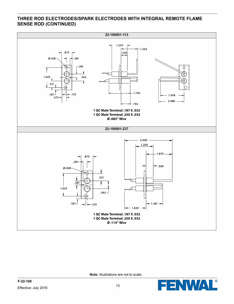
THREE ROD ELECTRODES/SPARK ELECTRODES WITH INTEGRAL REMOTE FLAME SENSE ROD (CONTINUED)
22-100001-113
1 QC Male Terminal .187 X .0321 QC Male Terminal .250 X .032
Ø .085” Wire
22-100001-237
1 QC Male Terminal .187 X .0321 QC Male Terminal .250 X .032
Ø .114” Wire
.750.750
1.7501.750
.500.500
1.3551.355
1.2501.250
1.9381.938
2.0862.086
1.6251.625
.875.875
.281.281
.281.281
.562.562
.125.125.187.187
.531.531
.375.375
Ø.208Ø.208
.281.281
1.6251.625
.187.187 .125.125
.562.562
.875.875
.531.531
.281.281
1.6251.625
1.1871.187
.500.500
1.8751.875
3.5003.500
1.2501.250
Ø.208Ø.208
13
Note: Illustrations are not to scale.
Effective: July 2016
F-22-100
Note: Illustrations are not to scale.
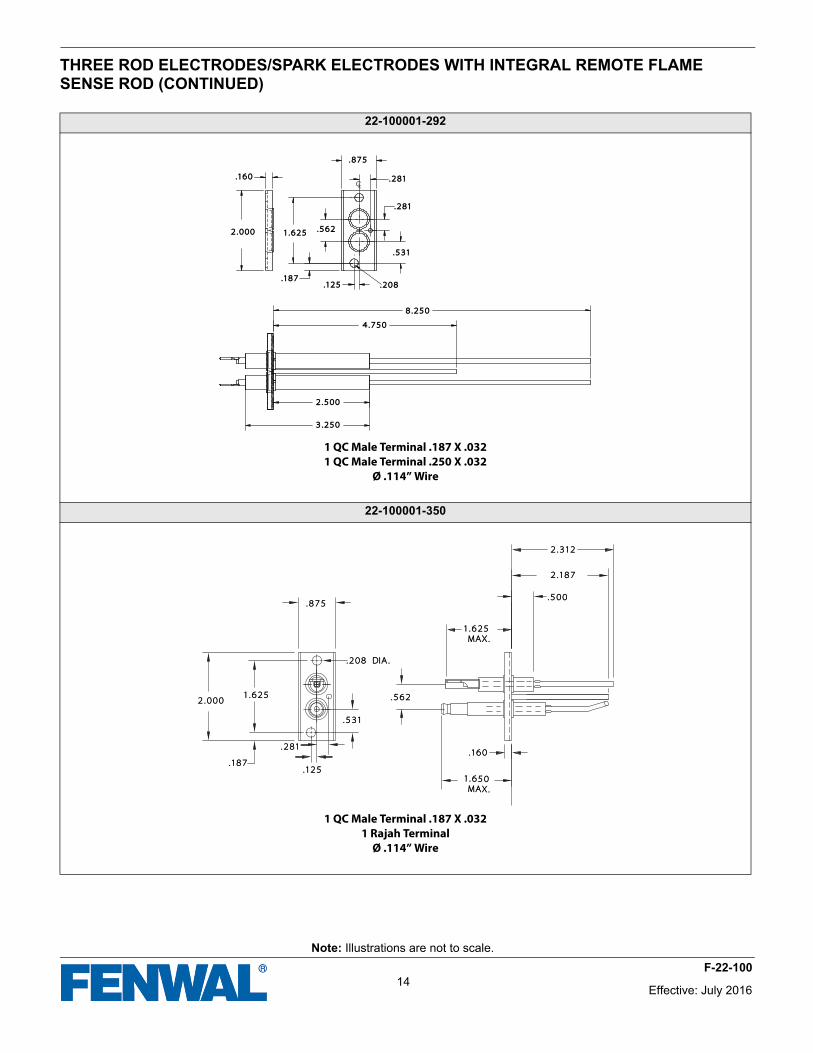
THREE ROD ELECTRODES/SPARK ELECTRODES WITH INTEGRAL REMOTE FLAME SENSE ROD (CONTINUED)
22-100001-292
1 QC Male Terminal .187 X .0321 QC Male Terminal .250 X .032
Ø .114” Wire
22-100001-350
1 QC Male Terminal .187 X .0321 Rajah Terminal
Ø .114” Wire
.160.160
2.0002.000 1.6251.625
.125.125.187.187
.531.531
.562.562
.281.281
.281.281
.875.875
.208.208
2.5002.500
3.2503.250
4.7504.750
8.2508.250
.875.875
.531.531
.125.125.187.187
2.0002.0001.6251.625 .562.562
.160.160
1.650 1.650 MAX.MAX.
1.625 1.625 MAX.MAX.
.500.500
2.1872.187
2.3122.312
.208 DIA..208 DIA.
.281.281
Effective: July 201614
F-22-100
Note: Illustrations are not to scale.
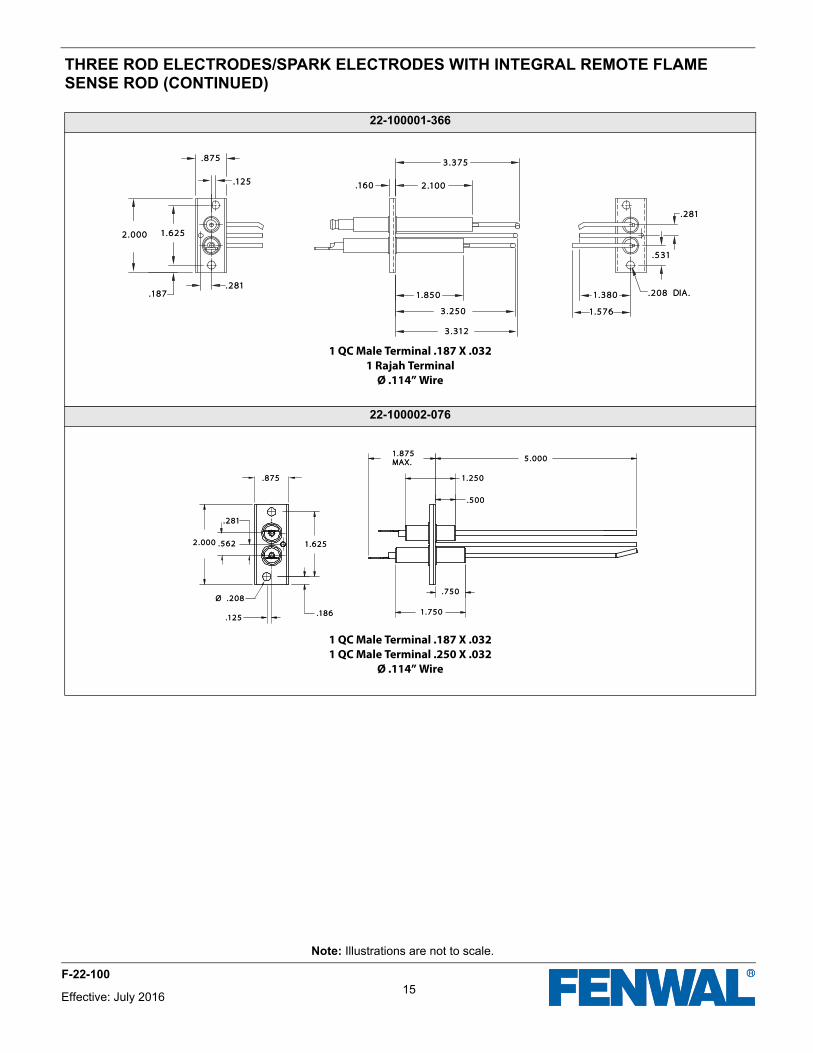
THREE ROD ELECTRODES/SPARK ELECTRODES WITH INTEGRAL REMOTE FLAME SENSE ROD (CONTINUED)
22-100001-366
1 QC Male Terminal .187 X .0321 Rajah Terminal
Ø .114” Wire
22-100002-076
1 QC Male Terminal .187 X .0321 QC Male Terminal .250 X .032
Ø .114” Wire
.125.125
.281.281.187.187
2.0002.000 1.6251.625
.875.875
1.8501.850
3.2503.250
3.3123.312
.160.160 2.1002.100
3.3753.375
1.5761.576
1.3801.380 .208 DIA..208 DIA.
.531.531
.281.281
.875.875
2.0002.000
1.7501.750
.750.750
1.6251.625
.186.186
.500.500
1.2501.250
5.0005.0001.875 1.875 MAX.MAX.
.125.125
Ø .208Ø .208
.562.562
.281.281
15Effective: July 2016
F-22-100

® ®
This literature is provided for informational purposes only. KIDDE-FENWAL, INC. assumes no responsibility for the prod-uct’s suitability for a particular application. The product must be properly applied to work correctly. If you need more information on this product, or if you have a particular problem or question, contact KIDDE-FENWAL, INC., Ashland, MA 01721.
© 2016 Kidde-Fenwal Inc. P/N F-22-100 Rev AC
Fenwal Controls, Kidde-Fenwal, Inc.400 Main StreetAshland, MA 01721Tel: 800-FENWAL-1Fax: 508-881-7619 www.fenwal.com
FENWAL and DETECT-A-FLAME are registered trademarks of Kidde-Fenwal Inc. All other trademarks are the property of their respective owners.