Embed Size (px)
Citation preview
KIBES® Body and Chassis Control
Multiplex system for commercial vehicles
www.continental-automotive.com/kibes
KIBES® − Key to integrated onboard electronic system.
Increasing requirements for efficiency, comfort and functionality affect the development of modern vehicles. The KIBES® hardware and software package from Continental can meet the challenge to fulfill them.
The KIBES® system will help to optimize the OEM ap plication – by reducing wirings, connectors, relays, and fuses the vehicle will become more reliable. The costs for wiring up the vehicle, as well as the expenses for documentation service and mainte-nance, will significantly drop.
With our KIBES® product portfolio, we provide an efficient development tool chain that offers a
scalable and flexible network system at a reasonable price, making buses, trucks and special vehicles more pow er ful, efficient and reliable.
Thanks to the KIBES®-32 / KIBES®-5 software the inte-gration and testing of application software is easy to handle and it supports flexible business models.
Advantages and base systems
The flexible network system of KIBES® allows an easy addition or removal of several components and it also simplifies the maintenance and trouble-shooting of the vehicle. Vehicles can be operated more safely and reliably due to built-in diagnostic features like short-circuit protection, open-load, and over-temperature detection.
The minimized amount of wirings, connectors, re lays and fuses allow for the vehicle weight and installation time to be significantly reduced, as well as the fuel consumption, documentation service and mainte-nance costs. At the same time, the vehicle reliability can be improved though high quality components that are carefully tested and validated not only on a component basis, but also on system level.
The system with central computer ZR5-A provides a solution to almost every possible requirement. Up to 18 nodes can be connected to ZR5-A for all types of in- and output signals. It offers a complex CAN network connectivity with powertrain CAN, customer generic CANs, instrument CAN, body CAN and three multiplex CANs. It is also possible to connect different instrument clusters and driver’s workplace solutions with a ZR5-A.
Systems with a control unit of the CBCU3 family provide powerful solutions that are optimized to meet any costumer requirement. Up to four nodes can be connected to CBCU3-E via multiplex CAN. Beyond that, control units of the CBCU3 family offer a network of powertrain CAN and instrument CAN, with the latter providing a direct connection to sever-al possible instrument cluster solutions.
The family of MUX5 provides a water protected system with the multiplex node MUX4-Pn for general purposes controlled by the master unit MUX5-Pcu. Up to four MUX4-Pn nodes per multiplex CAN can be connected to MUX5-Pcu. The system also provides four generic CANs, as well as the installation outside of the cabin. LIN as interfaces for intelligent switches, as well as separate intelligent sensor interfaces, round up the connectivity features for inside the vehicle.
Safety relevant functions compliant to ISO 26262 can be supported up to ASIL B. The customer enjoys high flexibility and will be able to program these functions on his own by using the KIBES tool chain and the KIBES®-5 safety manual.
KIBES®: Advantages and base systems 2
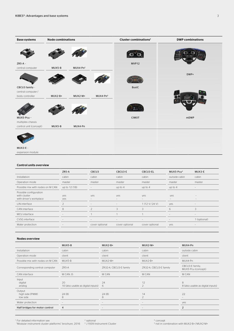
Base systems Node combinations Cluster combinations1 DWP combinations
ZR5-A –
central computer
MUX5-B
MUX4-Pn2
MVP12
DWP+
CBCU3 family –
central computer /
body controller MUX2-B+ MUX2-M+ MUX4-Pn5
BusIC
MUX5-Pcu −
multiplex chassis
control unit (concept) MUX5-B MUX4-Pn
CIMOT mDWP
MUX3-E –
expansion module
KIBES®: Advantages and base systems
Control units overview
ZR5-A CBCU3 CBCU3-E CBCU3-EL MUX5-Pcu4 MUX3-E
Installation cabin cabin cabin cabin outside cabin cabin
Operation mode master master master master master master
Possible mix with nodes on M CAN up to 12 (18) – up to 4 up to 4 up to 4 –
Possible configuration with cluster with driver’s workplace
yes yes
yes –
yes –
yes –
yes –
– –
LIN interface 2 – – 1 (12 V / 24 V) yes –
CAN interface 8 2 3 3 6 3
MCU interface – 1 1 1 – –
CVSG interface – – – – – 1 (optional)
Water protection – cover optional cover optional cover optional yes –
Nodes overview
MUX5-B MUX2-B+ MUX2-M+ MUX4-Pn
Installation cabin cabin cabin outside cabin
Operation mode client client client client
Possible mix with nodes on M CAN MUX5-B MUX2-M+ MUX2-B+ MUX4-Pn
Corresponding central computer ZR5-A ZR32-A, CBCU3-E family ZR32-A, CBCU3-E familyCBCU3-E family, MUX5-Pcu (concept)
CAN interface M CAN JS M CAN M CAN M CAN
Input digital analog
20 10 (also usable as digital inputs)
24 6
12 2
8 8 (also usable as digital inputs)
Output high side (PWM) low side
24 (8) 8
24 (8) 8
14 2
22 –
Water protection – – – yes
Half bridges for motor control 4 – – 2
1 For detailed information see “Modular instrument cluster platforms” brochure, 2016
2 optional3 J 1939 Instrument Cluster
4 concept5 not in combination with MUX2-B+ / MUX2-M+
3
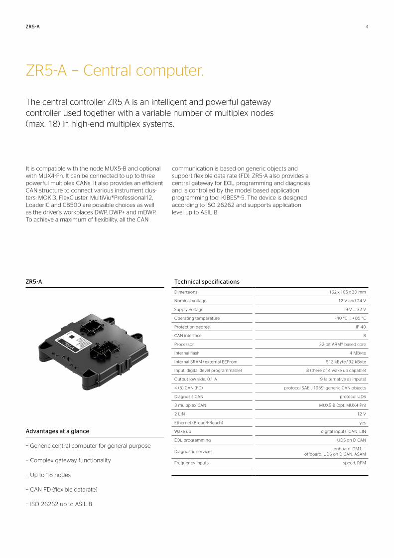
ZR5-A − Central computer.
The central controller ZR5-A is an intelligent and powerful gateway controller used together with a variable number of multiplex nodes (max. 18) in high-end multiplex systems.
It is compatible with the node MUX5-B and optional with MUX4-Pn. It can be connected to up to three powerful multiplex CANs. It also provides an efficient CAN structure to connect various instrument clus-ters: MOKI3, FlexCluster, MultiViu®Professional12, LoaderIC and CB500 are possible choices as well as the driver’s workplaces DWP, DWP+ and mDWP. To achieve a maximum of flexibility, all the CAN
communication is based on generic objects and sup port flexible data rate (FD). ZR5-A also provides a cen tral gateway for EOL programming and diagnosis and is controlled by the model based application programming tool KIBES®-5. The device is designed according to ISO 26262 and supports application level up to ASIL B.
ZR5-A
ZR5-A Technical specifications
Dimensions 162 x 165 x 30 mm
Nominal voltage 12 V and 24 V
Supply voltage 9 V .. . 32 V
Operating temperature - 40 °C . . . + 85 °C
Protection degree IP 40
CAN interface 8
Processor 32-bit ARM® based core
Internal flash 4 MByte
Internal SRAM / external EEProm 512 kByte / 32 kByte
Input, digital (level programmable) 8 (there of 4 wake up capable)
Output low side, 0.1 A 9 (alternative as inputs)
4 (5) CAN (FD) protocol SAE J 1939; generic CAN objects
Diagnosis CAN protocol UDS
3 multiplex CAN MUX5-B (opt. MUX4-Pn)
2 LIN 12 V
Ethernet (BroadR-Reach) yes
Wake up digital inputs, CAN, LIN
EOL programming UDS on D CAN
Diagnostic servicesonboard: DM1, . . .
offboard: UDS on D CAN, ASAM
Frequency inputs speed, RPM
Advantages at a glance
− Generic central computer for general purpose
− Complex gateway functionality
− Up to 18 nodes
− CAN FD (flexible datarate)
− ISO 26262 up to ASIL B
4
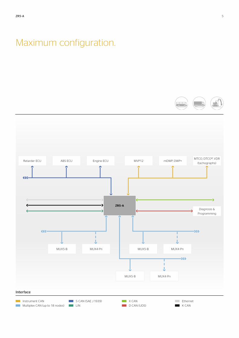
Maximum configuration.
ZR5-A
ZR5-A
MVP12
MUX5-BMUX5-B MUX4-Pn
mDWP, DWP+
MUX4-Pn
MTCO, DTCO®, VDR
(tachographs)
Diagnosis &
Programming
Retarder ECU ABS ECU Engine ECU
Interface
Instrument CAN
Multiplex CAN (up to 18 nodes)
5 CAN (SAE J 1939)
LIN
X CAN
D CAN (UDS)
Ethernet
K CAN
MUX5-B MUX4-Pn
5
Technical specifications
Dimensions 276 x 185 x 43 mm
Nominal voltage 24 V (12 V optional for CBCU3-EL)
Supply voltage 18 V .. . 32 V
Operating temperature - 40 °C . . . + 85 °C
Protection degree IP 30 (IP 54 with add. cover)
LIN interface only CBCU3-EL (1 x 12 / 24 V)
Processor 32-bit RISC
Internal flash 1024 kByte
External SRAM / external EEProm 256 kByte / 32 kByte
Input digital 8 mA 1 mA
34 16
Input analog (parametric) 6
Input frequency speed RPM
1 1
Input MSC interface 1
Output high side 7.5 A 5.6 A 3.6 A 2.7 A 1.8 A 1.0 A 0.2 A
1 3 3 6
10 5
4 (1 PWM)
Output low side, 1.0 A 2 (configuration a PWM)
Output power supply 8 V / 10 mA 5 V / 20 mA
2 1
Powertrain CANISO 11898, 250 kBaud, protocol SAE J 1939,
generic CAN objects
Instrument CANISO 11898, 250 kBaud, generic CAN objects,
compatible with CMIC, VDR
Multiplex CAN ISO 11898, 125 kBaud; for MUX2-B+ (max. 4 nodes)
Human machine interface MCU
Wake up5 digital inputs, (e. g. term 15, hazard switch),
5 free configurable inputs
EOL programming KWP2000 on K-line, powertrain CAN
Sensor supply 1 x 5 V / 20 mA; 2 x 8 V / 10 mA
Diagnostic servicesonboard: DM1
offboard: KWP2000 on K-line, ASAM, powertrain CAN
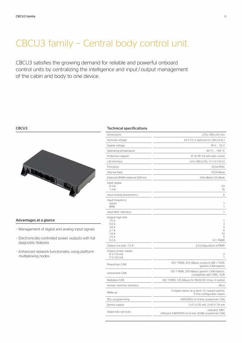
CBCU3 family − Central body control unit.
CBCU3 satisfies the growing demand for reliable and powerful onboard control units by centralizing the intelligence and input / output management of the cabin and body to one device.
CBCU3
CBCU3 family
Advantages at a glance
− Management of digital and analog input signals
− Electronically-controlled power outputs with full diagnostic features
− Enhanced network functionality using platform multiplexing nodes
6
CBCU3 family
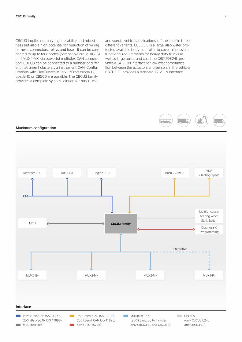
CBCU3 implies not only high reliability and robust-ness but also a high potential for reduction of wiring harness, connectors, relays and fuses. It can be con-nected to up to four nodes (compatible are MUX2-B+ and MUX2-M+) via powerful multiplex CAN connec-tion. CBCU3 can be connected to a number of differ-ent instrument clusters via instrument CAN. Config-urations with FlexCluster, MultiViu®Professional12, LoaderIC or CB500 are possible. The CBCU3 family provides a complete system solu tion for bus, truck
and special vehicle applications, off-the-shelf in three different variants: CBCU3-E is a large, also water pro-tected available body controller to cover all possible functional requirements for heavy duty trucks as well as large buses and coaches; CBCU3-E24L pro-vides a 24 V LIN interface for low-cost communica-tion between the actuators and sensors in the vehicle; CBCU3-EL provides a standard 12 V LIN interface.
CBCU3 family
BusIC / CIMOT
MUX2-B+
Retarder ECU ABS ECU Engine ECU
MUX2-M+MUX2-M+
VDR
(Tachographs)
MCU
MUX4-Pn
Diagnosis &
Programming
Multifunctional
Steering Wheel,
Stalk Switch
Interface
Powertrain CAN (SAE J 1939;
250 kBaud; CAN ISO 11898)
MCU interface
Instrument CAN (SAE J 1939;
250 kBaud; CAN ISO 11898)
K-line (ISO 15765)
Multiplex CAN
(250 kBaud; up to 4 nodes;
only CBCU3-EL and CBCU3-E)
LIN bus
(only CBCU3-E24L
and CBCU3-EL)
Maximum configuration
alternative
7
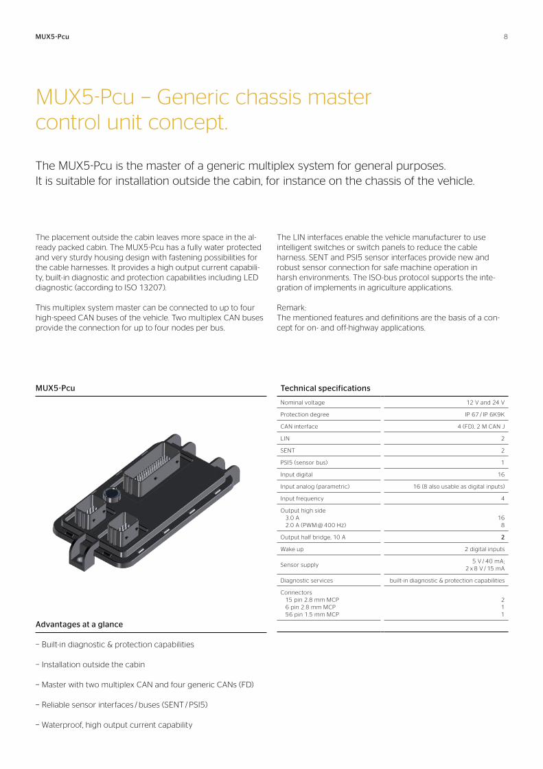
MUX5-Pcu − Generic chassis master control unit concept.
The MUX5-Pcu is the master of a generic multiplex system for general purposes. It is suitable for installation outside the cabin, for instance on the chassis of the vehicle.
The placement outside the cabin leaves more space in the al-ready packed cabin. The MUX5-Pcu has a fully water protected and very sturdy housing design with fastening possibilities for the cable harnesses. It provides a high output current capabili-ty, built-in diagnostic and protection capabilities including LED diagnostic (according to ISO 13207).
This multiplex system master can be connected to up to four high-speed CAN buses of the vehicle. Two multiplex CAN buses provide the connection for up to four nodes per bus.
The LIN interfaces enable the vehicle manufacturer to use intelligent switches or switch panels to reduce the cable harness. SENT and PSI5 sensor interfaces provide new and robust sensor connection for safe machine operation in harsh environments. The ISO-bus protocol supports the inte-gration of implements in agriculture applications.
Remark: The mentioned features and definitions are the basis of a con-cept for on- and off-highway applications.
Technical specifications
Nominal voltage 12 V and 24 V
Protection degree IP 67 / IP 6K9K
CAN interface 4 (FD), 2 M CAN J
LIN 2
SENT 2
PSI5 (sensor bus) 1
Input digital 16
Input analog (parametric) 16 (8 also usable as digital inputs)
Input frequency 4
Output high side 3.0 A 2.0 A (PWM @ 400 Hz)
16
8
Output half bridge, 10 A 2
Wake up 2 digital inputs
Sensor supply5 V / 40 mA;
2 x 8 V / 15 mA
Diagnostic services built-in diagnostic & protection capabilities
Connectors 15 pin 2.8 mm MCP 6 pin 2.8 mm MCP 56 pin 1.5 mm MCP
2 1 1
MUX5-Pcu
Advantages at a glance
− Built-in diagnostic & protection capabilities
− Installation outside the cabin
− Master with two multiplex CAN and four generic CANs (FD)
− Reliable sensor interfaces / buses (SENT / PSI5)
− Waterproof, high output current capability
MUX5-Pcu 8
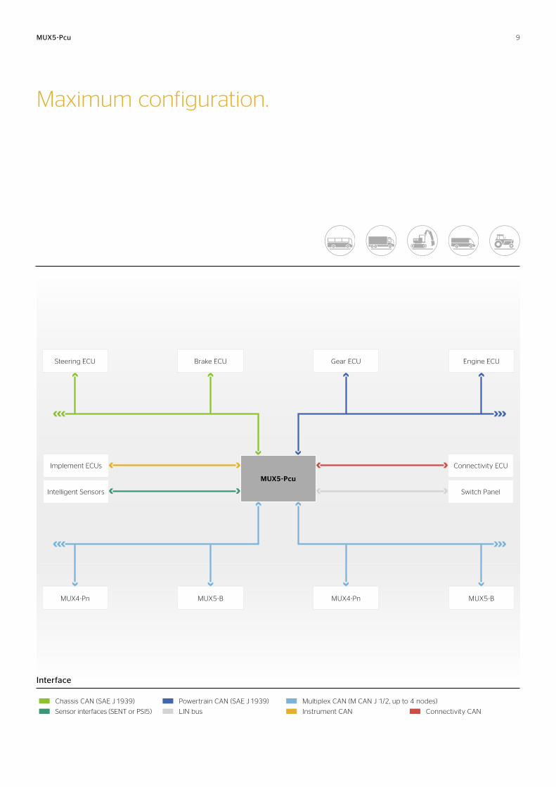
MUX5-Pcu
Maximum configuration.
Interface
MUX5-Pcu
Brake ECU Gear ECU Engine ECU
MUX4-Pn MUX4-PnMUX5-B MUX5-B
Steering ECU
Switch Panel
Connectivity ECU
Intelligent Sensors
Implement ECUs
Sensor interfaces (SENT or PSI5) LIN bus Instrument CAN Connectivity CAN
Chassis CAN (SAE J 1939) Powertrain CAN (SAE J 1939) Multiplex CAN (M CAN J 1/2, up to 4 nodes)
9
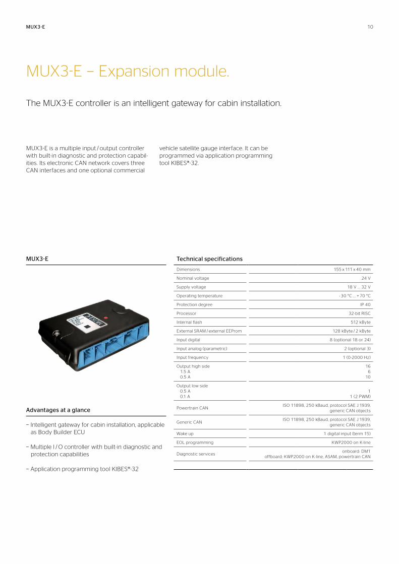
MUX3-E − Expansion module.
The MUX3-E controller is an intelligent gateway for cabin installation.
MUX3-E is a multiple input / output controller with built-in diagnostic and protection capabil-ities. Its electronic CAN network covers three CAN interfaces and one optional commercial
vehicle satel lite gauge interface. It can be programmed via application programming tool KIBES®-32.
MUX3-E Technical specifications
Dimensions 155 x 111 x 40 mm
Nominal voltage 24 V
Supply voltage 18 V .. . 32 V
Operating temperature - 30 °C . . . + 70 °C
Protection degree IP 40
Processor 32-bit RISC
Internal flash 512 kByte
External SRAM / external EEProm 128 kByte / 2 kByte
Input digital 8 (optional 18 or 24)
Input analog (parametric) 2 (optional 3)
Input frequency 1 (0-2000 Hz)
Output high side 1.5 A 0.5 A
16 6
10
Output low side 0.5 A 0.1 A
1
1 (2 PWM)
Powertrain CANISO 11898, 250 kBaud, protocol SAE J 1939,
generic CAN objects
Generic CANISO 11898, 250 kBaud, protocol SAE J 1939,
generic CAN objects
Wake up 1 digital input (term 15)
EOL programming KWP2000 on K-line
Diagnostic servicesonboard: DM1
offboard: KWP2000 on K-line, ASAM, powertrain CAN
Advantages at a glance
− Intelligent gateway for cabin installation, applicable as Body Builder ECU
− Multiple I / O controller with built-in diagnostic and protection capabilities
− Application programming tool KIBES®-32
MUX3-E 10
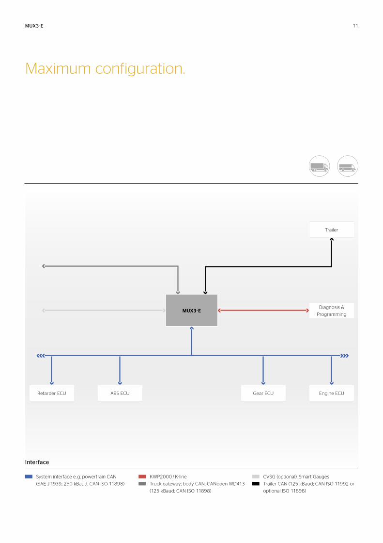
MUX3-E
Interface
System interface e. g. powertrain CAN
(SAE J 1939, 250 kBaud, CAN ISO 11898)
KWP2000 / K-line
Truck gateway; body CAN; CANopen WD413
(125 kBaud; CAN ISO 11898)
CVSG (optional), Smart Gauges
Trailer CAN (125 kBaud; CAN ISO 11992 or
optional ISO 11898)
Trailer
MUX3-E
ABS ECU Gear ECU Engine ECURetarder ECU
Diagnosis &
Programming
Maximum configuration.
11
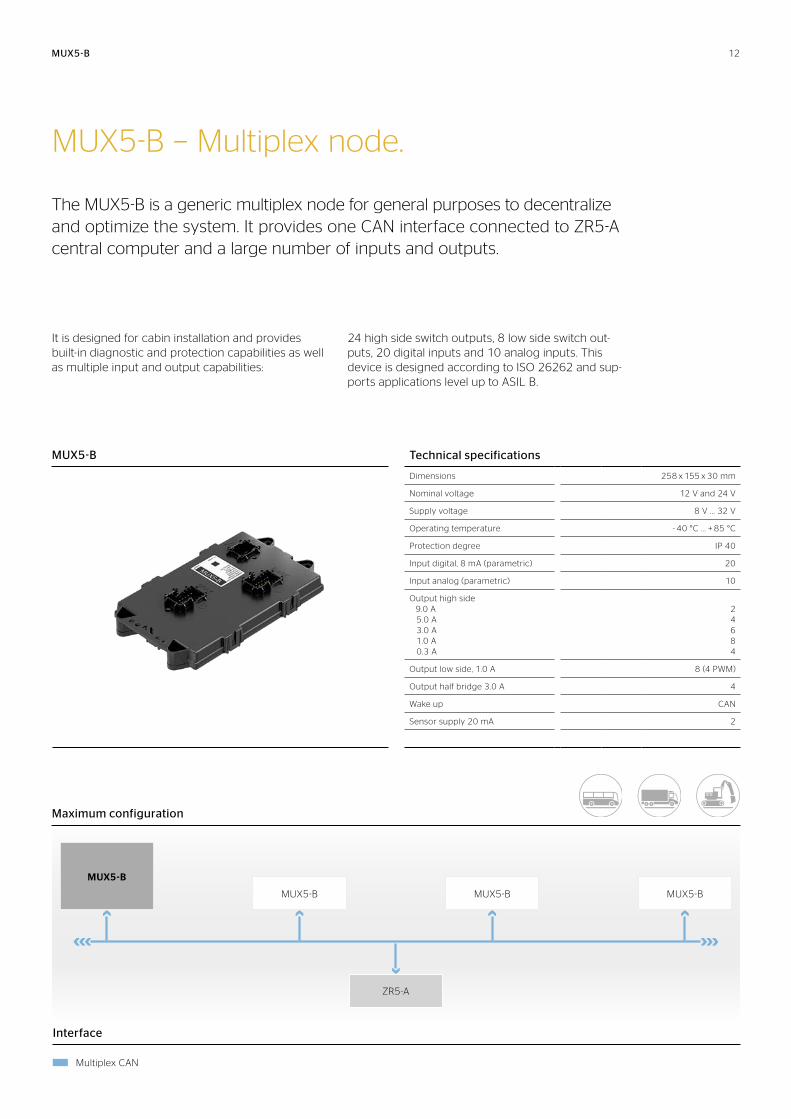
MUX5-B − Multiplex node.
The MUX5-B is a generic multiplex node for general purposes to decentralize and optimize the system. It provides one CAN interface connected to ZR5-A central computer and a large number of inputs and outputs.
It is designed for cabin installation and provides built-in diagnostic and protection capabilities as well as multiple input and output capabilities:
24 high side switch outputs, 8 low side switch out-puts, 20 digital inputs and 10 analog inputs. This device is designed according to ISO 26262 and sup-ports applications level up to ASIL B.
Technical specifications
Dimensions 258 x 155 x 30 mm
Nominal voltage 12 V and 24 V
Supply voltage 8 V .. . 32 V
Operating temperature - 40 °C . . . + 85 °C
Protection degree IP 40
Input digital, 8 mA (parametric) 20
Input analog (parametric) 10
Output high side 9.0 A 5.0 A 3.0 A 1.0 A 0.3 A
2 4 6 8 4
Output low side, 1.0 A 8 (4 PWM)
Output half bridge 3.0 A 4
Wake up CAN
Sensor supply 20 mA 2
MUX5-B
MUX5-B
Interface
Multiplex CAN
Maximum configuration
MUX5-B
MUX5-B MUX5-B MUX5-B
ZR5-A
12
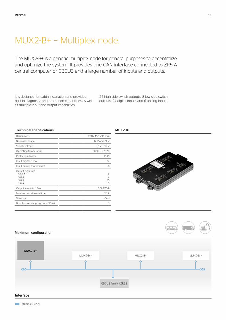
MUX2-B+ − Multiplex node.
The MUX2-B+ is a generic multiplex node for general purposes to decentralize and optimize the system. It provides one CAN interface connected to ZR5-A central computer or CBCU3 and a large number of inputs and outputs.
It is designed for cabin installation and provides built-in diagnostic and protection capabilities as well as multiple input and output capabilities:
24 high side switch outputs, 8 low side switch outputs, 24 digital inputs and 6 analog inputs.
Technical specifications
Dimensions 258 x 155 x 30 mm
Nominal voltage 12 V and 24 V
Supply voltage 8 V .. . 32 V
Operating temperature - 30 °C . . . + 70 °C
Protection degree IP 40
Input digital, 8 mA 24
Input analog (parametric) 6
Output high side 10.0 A 5.0 A 3.0 A 1.0 A
2 4
10 8
Output low side, 1.0 A 8 (4 PWM)
Max. current at same time 30 A
Wake up CAN
No. of power supply groups (15 A) 5
MUX2-B
MUX2-B+
Interface
Multiplex CAN
Maximum configuration
MUX2-B+
MUX2-M+ MUX2-B+ MUX2-M+
CBCU3 family / ZR32
13
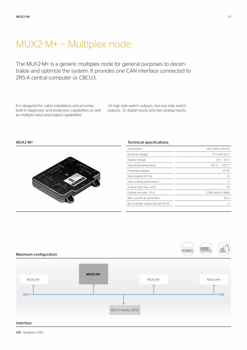
MUX2-M+ − Multiplex node.
The MUX2-M+ is a generic multiplex node for general purposes to decen-tralize and optimize the system. It provides one CAN interface connected to ZR5-A central computer or CBCU3.
It is designed for cabin installation and provides built-in diagnostic and protection capabilities as well as multiple input and output capabilities:
14 high side switch outputs, two low side switch outputs, 12 digital inputs and two analog inputs.
MUX2-M+
MUX2-M+
Technical specifications
Dimensions 162 x 165 x 30 mm
Nominal voltage 12 V and 24 V
Supply voltage 8 V .. . 32 V
Operating temperature - 30 °C . . . + 70 °C
Protection degree IP 40
Input digital, 8.0 mA 12
Input analog (parametric) 2
Output high side, 3.0 A 14
Output low side, 1.0 A 2 (HB switch, PWM)
Max. current at same time 25 A
No. of power supply groups (15 A) 2
Interface
Multiplex CAN
Maximum configuration
MUX2-B+
MUX2-M+
MUX2-B+ MUX2-M+
CBCU3 family / ZR32
14
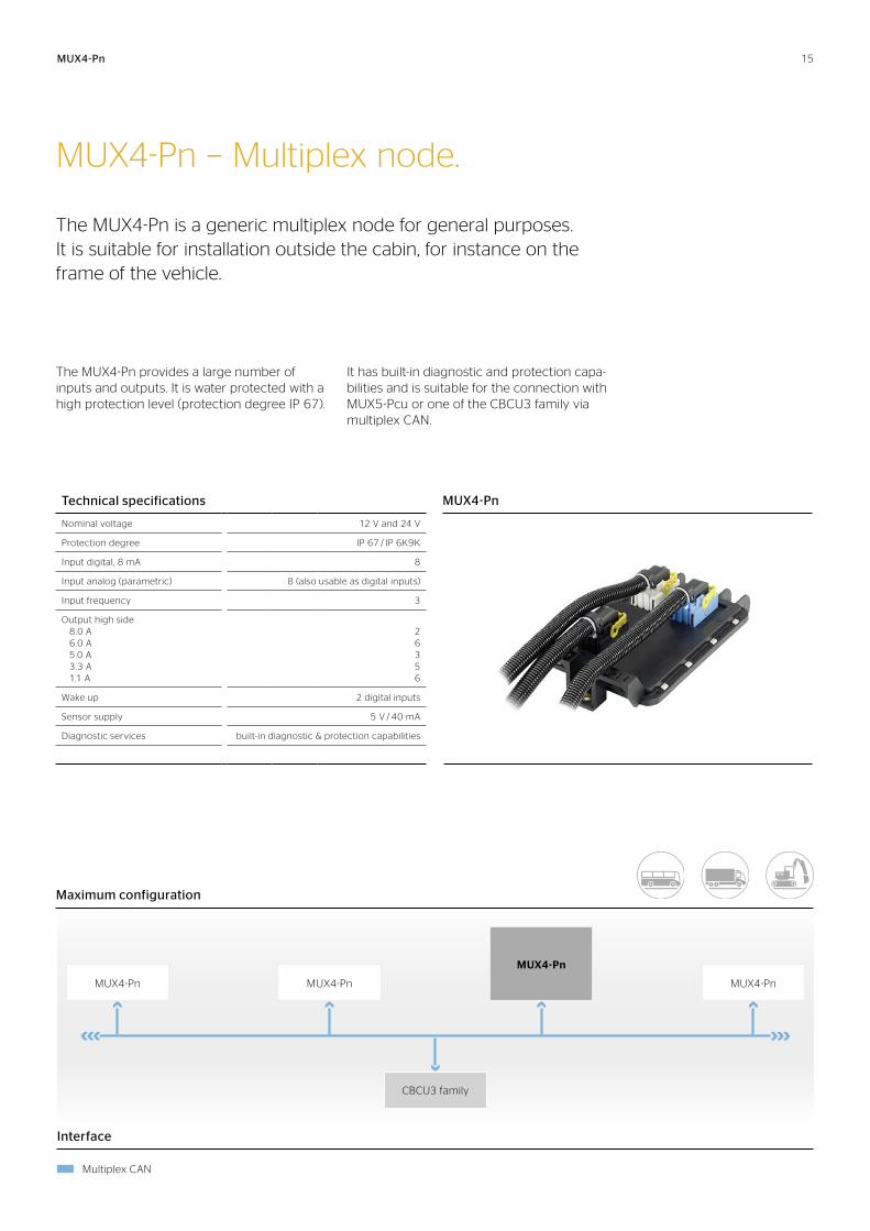
MUX4-Pn − Multiplex node.
The MUX4-Pn is a generic multiplex node for general purposes. It is suitable for installation outside the cabin, for instance on the frame of the vehicle.
The MUX4-Pn provides a large number of inputs and outputs. It is water protected with a high protection level (protection degree IP 67).
It has built-in diagnostic and protection capa-bilities and is suitable for the connection with MUX5-Pcu or one of the CBCU3 family via multiplex CAN.
Technical specifications
Nominal voltage 12 V and 24 V
Protection degree IP 67 / IP 6K9K
Input digital, 8 mA 8
Input analog (parametric) 8 (also usable as digital inputs)
Input frequency 3
Output high side 8.0 A 6.0 A 5.0 A 3.3 A 1.1 A
2 6 3 5 6
Wake up 2 digital inputs
Sensor supply 5 V / 40 mA
Diagnostic services built-in diagnostic & protection capabilities
MUX4-Pn
MUX4-Pn
MUX4-Pn MUX4-Pn
MUX4-Pn
MUX4-Pn
CBCU3 family
Interface
Multiplex CAN
Maximum configuration
15
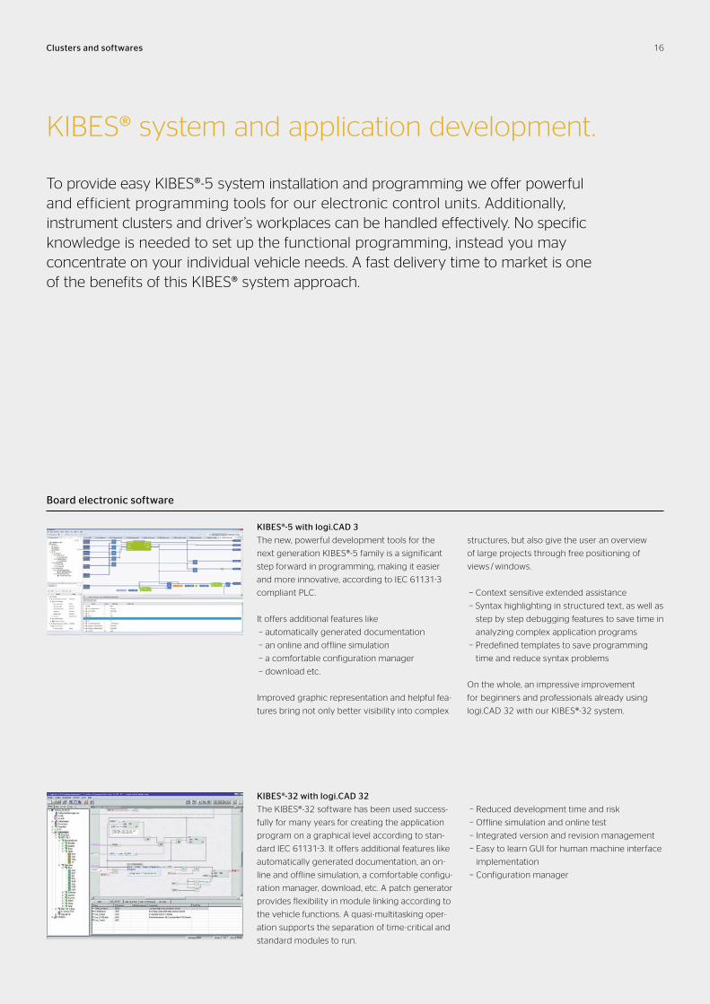
KIBES® system and application development.
To provide easy KIBES®-5 system installation and programming we offer powerful and efficient programming tools for our electronic control units. Additionally, instrument clusters and driver’s workplaces can be handled effectively. No specific knowledge is needed to set up the functional programming, instead you may concentrate on your individual vehicle needs. A fast delivery time to market is one of the benefits of this KIBES® system approach.
Board electronic software
KIBES®-5 with logi.CAD 3
The new, powerful development tools for the
next generation KIBES®-5 family is a significant
step forward in programming, making it easier
and more innovative, according to IEC 61131-3
compliant PLC.
It offers additional features like
− automatically generated documentation
− an online and offline simulation
− a comfortable configuration manager
− download etc.
Improved graphic representation and helpful fea-
tures bring not only better visibility into complex
structures, but also give the user an overview
of large projects through free positioning of
views / windows.
− Context sensitive extended assistance
− Syntax highlighting in structured text, as well as
step by step debugging features to save time in
analyzing complex application programs
− Predefined templates to save programming
time and reduce syntax problems
On the whole, an impressive improvement
for beginners and professionals already using
logi.CAD 32 with our KIBES®-32 system.
Clusters and softwares
KIBES®-32 with logi.CAD 32
The KIBES®-32 software has been used success-
fully for many years for creating the application
program on a graphical level according to stan-
dard IEC 61131-3. It offers additional features like
automatically generated documentation, an on-
line and offline simulation, a comfortable configu-
ration manager, download, etc. A patch generator
provides flexibility in module linking according to
the vehicle functions. A quasi-multitasking oper-
ation supports the separation of time-critical and
standard modules to run.
− Reduced development time and risk
− Offline simulation and online test
− Integrated version and revision management
− Easy to learn GUI for human machine interface
implementation
− Configuration manager
16
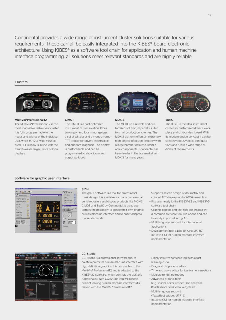
Clusters
BusIC
The BusIC is the ideal instrument
cluster for customized driver’s work-
place and citybus dashboard. With
its module design concept it can be
used in various vehicle configura-
tions and fulfills a wide range of
different requirements.
CIMOT
The CIMOT is a cost-optimized
in strument cluster solution. It has
two major and four minor gauges,
a set of telltales and a monochrome
TFT display for drivers’ information
and onboard diagnosis. The display
is customizable and can be
programmed to show icons and
corporate logos.
MOKI3
The MOKI3 is a reliable and cus-
tomized solution, especially suited
to small production volumes. The
MOKI3 platform offers an extremely
high degree of design flexibility with
a large number of fully customiz-
able components. Continental has
been leader in the bus market with
MOKI3 for many years.
MultiViu®Professional12
The MultiViu®Professional12 is the
most innovative instrument cluster.
It is fully programmable to the
needs and wishes of the individual
user, while its 12.3" wide-view col-
ored TFT-Display is in line with the
trend towards larger, more colorful
displays.
Software for graphic user interface
grADI
The grADI software is a tool for professional
mask design. It is available for many commercial
vehicle clusters and display products like MOKI3,
CIMOT and BusIC by Continental. It gives cus-
tomers the possibility to create their own graphic
human machine interface and to easily adapt to
market demands.
− Supports screen design of dot-matrix and
colored TFT displays up to WVGA resolution
− Fits seamlessly to the KIBES®-32 and KIBES®-5
software tool chain
− Graphic objects and text files are created by
a common software tool like Adobe and can
be easily imported into grADI
− Multi-language support for international
applications
− Development tool based on CINEMA 4D
− Intuitive GUI for human machine interface
implementation
CGI Studio
CGI Studio is a professional software tool to
create a premium human machine interface with
high definition graphics. It is compatible to the
MultiViu®Professional12 and is adapted to the
KIBES®-32 software, which controls the cluster’s
functionality. With CGI Studio you will receive
brilliant looking human machine inter faces dis-
played with the MultiViu®Professional12.
− Highly intuitive software tool with a fast
learning curve
− Drag and drop scene editor
− Time and curve editor for key frame animations
− Multiple rendering modes
− Advanced graphic tools
(e. g. shader editor, render time analysis)
− Benefits from Continental widgets set
− Multi-language support
(Texteffect Widget, UTF16)
− Intuitive GUI for human machine interface
implementation
Continental provides a wide range of instrument cluster solutions suitable for various requirements. These can all be easily integrated into the KIBES® board electronic ar chitecture. Using KIBES® as a software tool chain for application and human machine interface programming, all solutions meet relevant standards and are highly reliable.
17
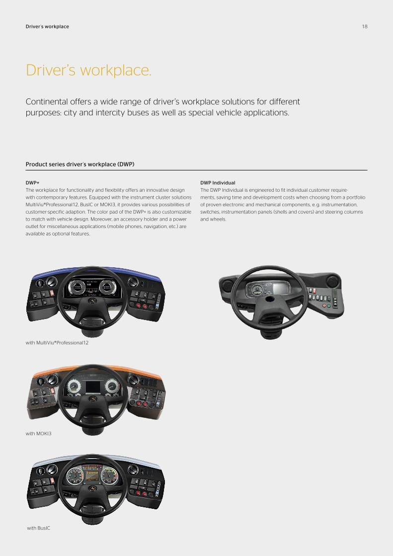
Product series driver’s workplace (DWP)
Driver ’s workplace
Driver’s workplace.
Continental offers a wide range of driver’s workplace solutions for different purposes: city and intercity buses as well as special vehicle applications.
DWP+
The workplace for functionality and flexibility offers an innovative design
with contemporary features. Equipped with the instrument cluster solutions
MultiViu®Professional12, BusIC or MOKI3, it provides various possibilities of
customer-specific adaption. The color pad of the DWP+ is also customizable
to match with vehicle design. Moreover, an accessory holder and a power
outlet for miscellaneous applications (mobile phones, navigation, etc.) are
available as optional features.
DWP Individual
The DWP Individual is engineered to fit individual customer require -
ments, saving time and development costs when choosing from a portfolio
of proven electronic and mechanical components, e. g. instrumentation,
switches, instrumentation panels (shells and covers) and steering columns
and wheels.
with MOKI3
with BusIC
with MultiViu®Professional12
18
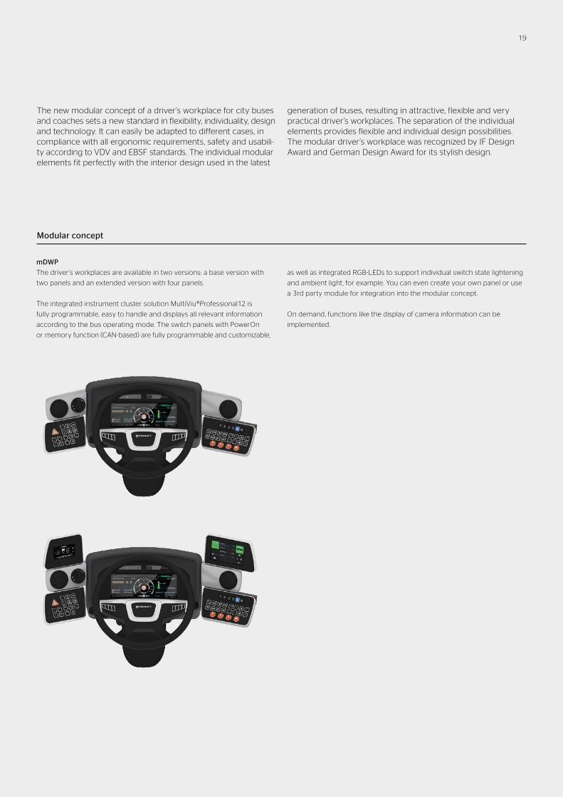
The new modular concept of a driver’s workplace for city buses and coaches sets a new standard in flexibility, individuality, design and technology. It can easily be adapted to different cases, in compliance with all ergonomic requirements, safety and usabili-ty according to VDV and EBSF standards. The individual modular elements fit perfectly with the interior design used in the latest
generation of buses, resulting in attractive, flexible and very practical driver’s workplaces. The separation of the individual elements provides flexible and individual design possibilities. The modular driver’s workplace was recognized by IF Design Award and German Design Award for its stylish design.
Modular concept
mDWP
The driver’s workplaces are available in two versions: a base version with
two panels and an extended version with four panels.
The integrated instrument cluster solution MultiViu®Professional12 is
fully programmable, easy to handle and displays all relevant information
according to the bus operating mode. The switch panels with PowerOn
or memory function (CAN-based) are fully programmable and customizable,
as well as integrated RGB-LEDs to support individual switch state lightening
and ambient light, for example. You can even create your own panel or use
a 3rd party module for integration into the modular concept.
On demand, functions like the display of camera information can be
implemented.
19
Co
nti
ne
nta
l Au
tom
oti
ve G
mb
H l
En
gli
sh ©
20
17
l P
rin
ted
in G
erm
an
y
Continental Automotive GmbH
Sodener Straße 9
65824 Schwalbach am Taunus
Germany
Tel. +49 6196 87-0
Heinrich-Hertz-Straße 45
78052 Villingen-Schwenningen
Germany
Tel. +49 7721 67-0
www.continental-corporation.com
Legal notice
The information provided in this brochure contains only
general descriptions or performance characteristics, which
do not always apply as described in case of actual use or
which may change as a result of further develop ment of the
products. This information is merely a technical description
of the product. This information is not meant or intended to
be a special guarantee for a particular quality or particular
durability. An obligation to provide the respective charac-
teristics shall only exist if expressly agreed in the terms of
contract. We reserve the right to make changes in availabili-
ty as well as technical changes without prior notice.