Embed Size (px)
Citation preview
ENGG1100 Introduction to Engineering Design
Faculty of Engineering
The Chinese University of Hong Kong
Laboratory 2: Electronics Basics I
Week 4, 2013 Fall
Welcome to the first electronic lab in this course. As you may have learnt of it last week, the aim of this course is to introduce to you the basic concepts of mechanical engineering, electronic engineering and computer engineering. In particular, electronics will play a very important role here.
The objective of this laboratory session (and the following lab) is to learn basic electronic graphical language and practical skills. We will introduce you how to construct circuit from schematic and how to use various instruments. Your TAs will guide you through the lab in a step-by-step manner.
By completing this laboratory session, you should know:
1. how to read schematic and implement the circuit described;2. how to use multimeters to perform various kinds of measurements;3. how to make circuits with breadboard;
ENGG 1100 Lab 2 1 EE/2013 Fall
Recording data properly from a laboratory experiment is part of the learning process in this course. As such, you are required to design and fill in a lab sheet attached at the end of this lab manual. We will provide Lab Sheet templates/examples of Lab 2 and Lab 3 ( provided in eLearning system). However, from Lab 5 and onwards, you will be required to prepare your own lab sheets *BEFORE* attending the lab. Without proper preparation, you are not allowed to start your lab.
Please read the lab manual thoroughly before attending the
lab!
ENGG 1100 Lab 2 2 EE/2013 Fall
1. Circuits, Schematics and Electronics
As an engineer, a fundamental skill that you need to master is how to read professional diagrams. In this section, we will learn what a circuit is, how to read schematics of electronic circuits and how to implement them as real circuits.
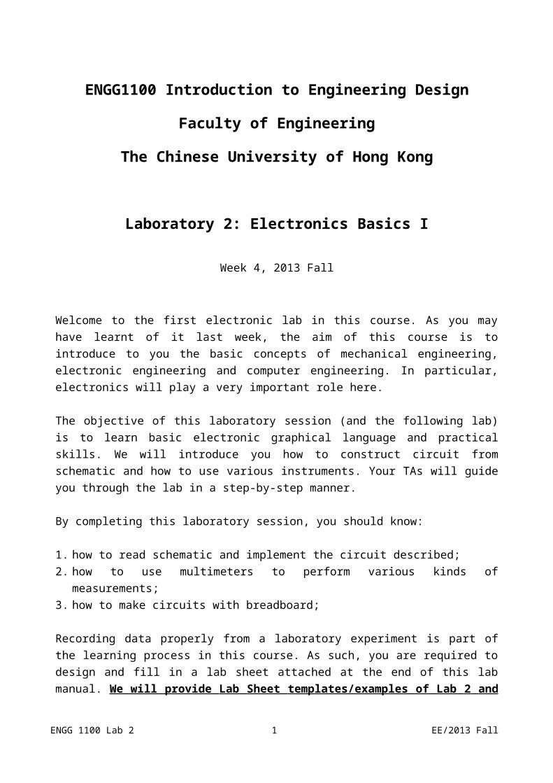
Schematics are made up of component symbols and connections. You may consult the diagram below for some common examples of the component symbols.
Figure 1: Symbols of different electronic components
We will revisit the usage of some of these components in later laboratory sessions.
Schematics are diagrams that describe how electronic components are connected to make useful circuits. Simply speaking, assembling a circuit is about making connections between the components. As such, it is very important to learn how to read schematics. There are some basic rules that you should be aware of while reading/drawing/implementing a schematic.
There are a few rules about drawing a schematic:
1. A circuit must contain a closed loop or else there will be no current flow and non-functional.2. A circuit usually contains a power source.3. Connections are treated as nodes. Each node is considered as a set of Electrical Connection.
ENGG 1100 Lab 2 3 EE/2013 Fall

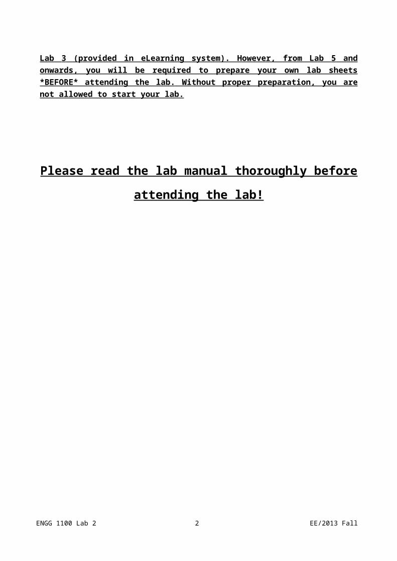
A circuit must contain a closed loop
Figure 2: Closed loop circuits
A closed loop means that electricity can flow through the circuit and return to the position that it originates from. Without a closed loop, the circuit is open and the circuit cannot function.
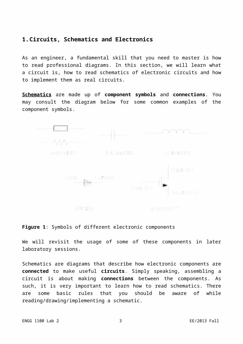
A circuit usually contains a power sourceA power source can be represented in a number of ways (here, we only show the illustrations for a direct current (DC) power source):
Figure 3: Different representations of power sources
You may notice that the last representation does not seem to give a closed loop circuit. In fact, it is still describing a closed loop circuit. Moreover, the three circuits shown are essentially the same.
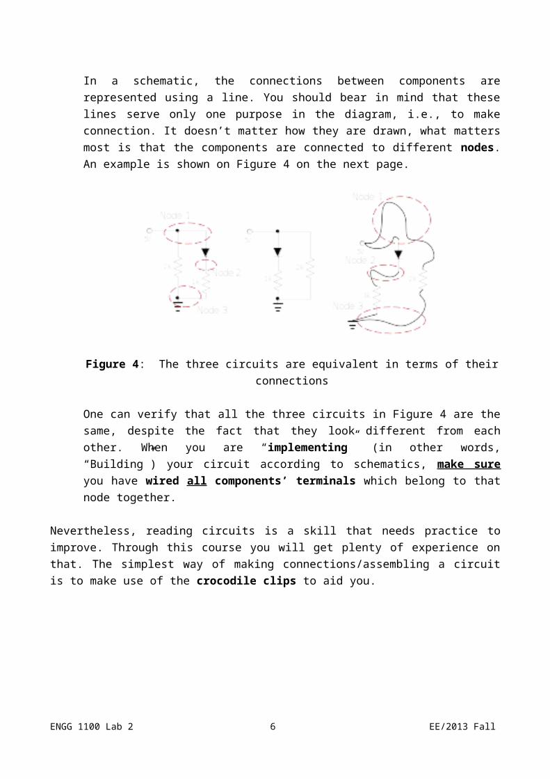
Connections are treated as nodesIn a schematic, the connections between components are represented using a line. You should bear in mind that these lines serve only one purpose in the diagram, i.e., to make connection. It doesn’t matter how they are drawn, what matters most is that the
ENGG 1100 Lab 2 4 EE/2013 Fall
components are connected to different nodes. An example is shown on Figure 4 on the next page.
Figure 4: The three circuits are equivalent in terms of their connections
One can verify that all the three circuits in Figure 4 are the same, despite the fact that they look different from each other. When you are “implementing” (in other words, “Building”) your circuit according to schematics, make sure you have wired all components’ terminals which belong to that node together.
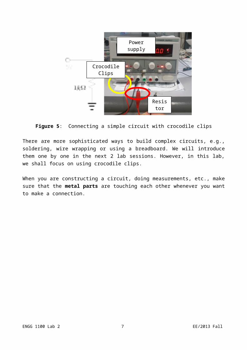
Nevertheless, reading circuits is a skill that needs practice to improve. Through this course you will get plenty of experience on that. The simplest way of making connections/assembling a circuit is to make use of the crocodile clips to aid you.
Figure 5: Connecting a simple circuit with crocodile clips
ENGG 1100 Lab 2 5 EE/2013 Fall
Crocodile Clips
Resistor
Power supply
There are more sophisticated ways to build complex circuits, e.g., soldering, wire wrapping or using a breadboard. We will introduce them one by one in the next 2 lab sessions. However, in this lab, we shall focus on using crocodile clips.
When you are constructing a circuit, doing measurements, etc., make sure that the metal parts are touching each other whenever you want to make a connection.
ENGG 1100 Lab 2 6 EE/2013 Fall
2. Multimeter
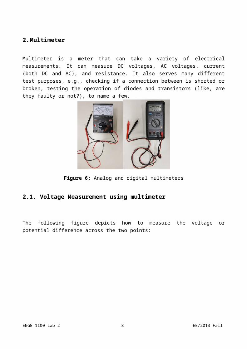
Multimeter is a meter that can take a variety of electrical measurements. It can measure DC voltages, AC voltages, current (both DC and AC), and resistance. It also serves many different test purposes, e.g., checking if a connection between is shorted or broken, testing the operation of diodes and transistors (like, are they faulty or not?), to name a few.
Figure 6: Analog and digital multimeters
2.1. Voltage Measurement using multimeter
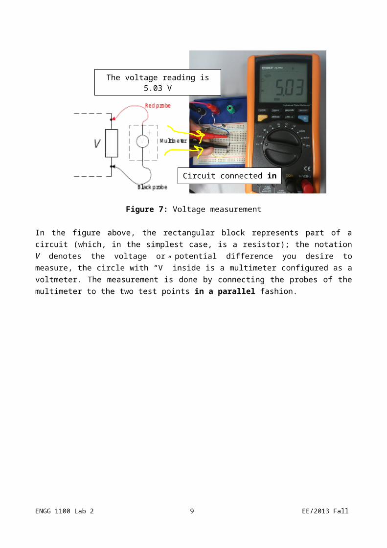
The following figure depicts how to measure the voltage or potential difference across the two points:
Figure 7: Voltage measurement
In the figure above, the rectangular block represents part of a circuit (which, in the simplest case, is
ENGG 1100 Lab 2 7 EE/2013 Fall
The voltage reading is 5.03 V
Circuit connected in parallel
a resistor); the notation V denotes the voltage or potential difference you desire to measure, the circle with “V” inside is a multimeter configured as a voltmeter. The measurement is done by connecting the probes of the multimeter to the two test points in a parallel fashion.
ENGG 1100 Lab 2 8 EE/2013 Fall
Important remarks:1. Polarity matters. The red probe corresponds to “+”, while the black probe corresponds “-”.2. Dial the function knob to the desired kind of measurement. In this section, it is voltage.
Moreover, the function knob allows you to choose the maximum range of the measured value (the range selection would be automatic in digital multimeters). Choose the range that would give you the most accurate reading possible.
2.2. Current Measurement using multimeter
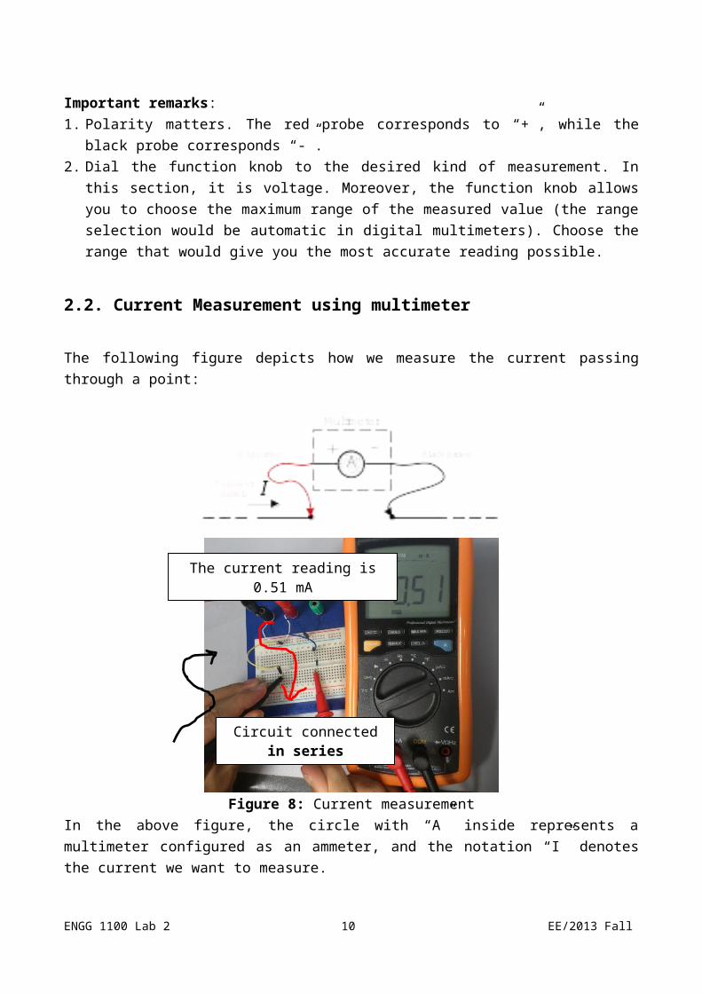
The following figure depicts how we measure the current passing through a point:
Figure 8: Current measurementIn the above figure, the circle with “A” inside represents a multimeter configured as an ammeter, and the notation “I” denotes the current we want to measure.
Important remarks:
1. Dial the function knob to current. 2. For current measurement, a multimeter should always be connected IN SERIES with the circuit
as shown in Figure 8.
ENGG 1100 Lab 2 9 EE/2013 Fall
The current reading is 0.51 mA
Circuit connected in series
3. Some digital multimeter may require plugging the +ve probe in a different socket from the one used for voltage/resistance measurement.
4. Improper current measurement can damage the multimeter. If the current to be measured is higher than the maximum range of current set in the multimeter, you run the risk of blowing the fuse. Always choose the current range wisely.
2.3. Resistance Measurement using multimeter
To measure the resistance between two points, the connection is the same as that for voltage measurement in Figure 7, i.e., in parallel. However, you have to switch off ALL the power supplied to the circuit.
3. Using breadboard for circuit assembly
As illustrated in Figure 9, breadboard is a circuit board with many pre-connected holes in it:
Figure 9: A real breadboard (left) and connection assignment of it (right)
Constructing circuits using breadboard is very easy especially if you are familiar with the “node” concept which is just introduced. For instance, each connected line (e.g. a blue one or a red one in Figure 9) is seen as a node to which the electronic components are connected.
Let us demonstrate this by showing an example circuit:
ENGG 1100 Lab 2 10 EE/2013 Fall
To 5V of power supplyTo GND of power supply
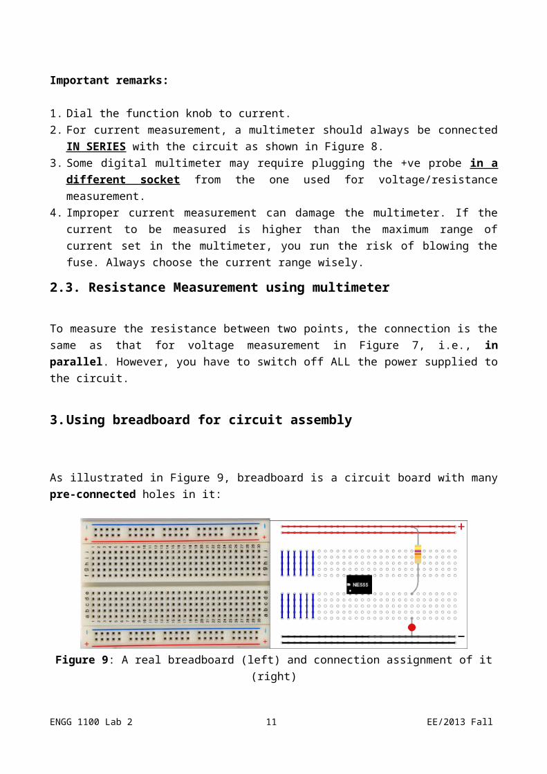
Figure 10: Practical example showing how to connect a circuit on breadboard
From the above figure, you can see how the pre-connected holes can help you in connecting the circuit. Just imagine how messy would the connection be if you are going to connect the same circuit using crocodile clips.4. Elementary component: Resistors
Resistor is a basic electronic component that appears in every electronic circuit. To begin with, let us see how a resistor looks like:
Figure 11: Resistor and its equivalent electronic symbol
In practice, we will read the Color Band Code marked on the resistor to identify the resistance value of it. At the moment, we will use multimeter to measure the value directly. There are plenty of resource on the Internet that teach us how to read those codes. For example: http://www.elexp.com/tips/clr_code.gif from Electronix Express.
4.1 Voltage divider network – the theory
ENGG 1100 Lab 2 11 EE/2013 Fall
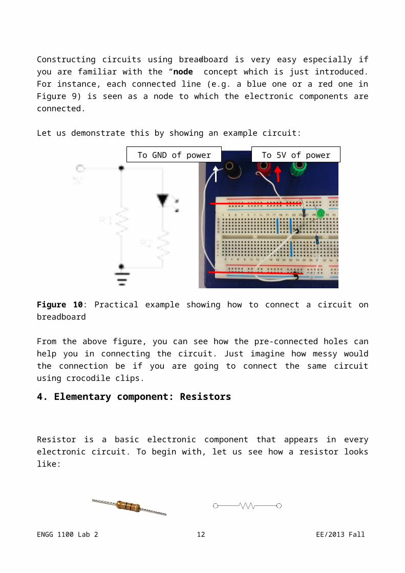
Figure 12: Voltage divider circuit
The circuit in Figure 12 demonstrated the principle of voltage divider. In particular, the voltage across R2 follows the following equation, which can be deduced from Ohm’s Law:
.
As you can see, the two resistors R1 and R2 divide the voltage provided to the circuit proportionally.
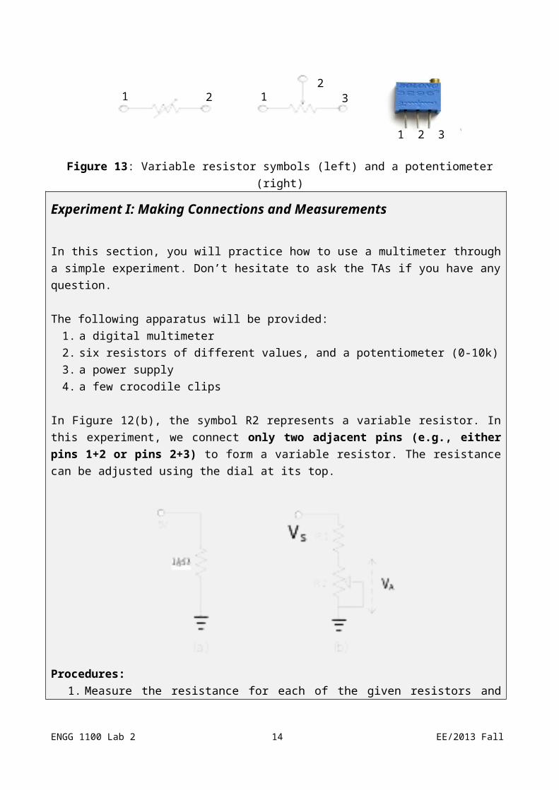
Voltage divider network is often constructed with variable resistors and potentiometer.
Figure 13: Variable resistor symbols (left) and a potentiometer (right)
ENGG 1100 Lab 2 12 EE/2013 Fall
1 2 3
212
31

Experiment I: Making Connections and Measurements
In this section, you will practice how to use a multimeter through a simple experiment. Don’t hesitate to ask the TAs if you have any question.
The following apparatus will be provided:1. a digital multimeter2. six resistors of different values, and a potentiometer (0-10k)3. a power supply4. a few crocodile clips
In Figure 12(b), the symbol R2 represents a variable resistor. In this experiment, we connect only two adjacent pins (e.g., either pins 1+2 or pins 2+3) to form a variable resistor. The resistance can be adjusted using the dial at its top.
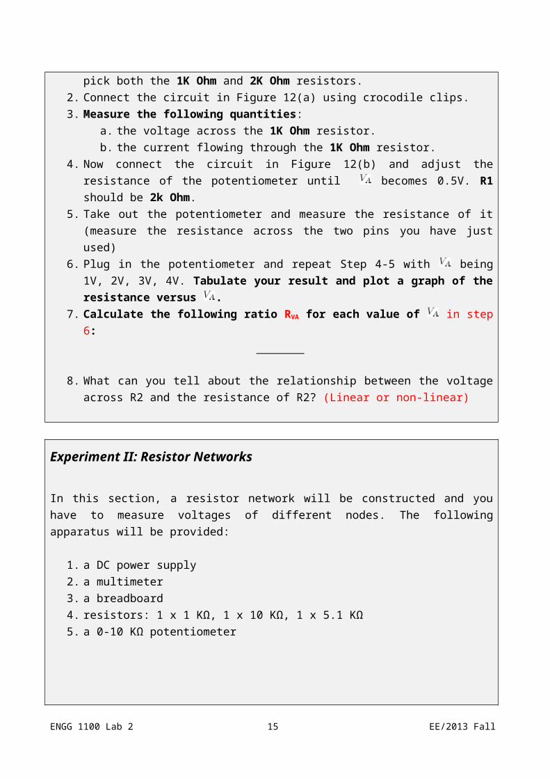
Procedures:1. Measure the resistance for each of the given resistors and pick both the 1K Ohm and 2K
Ohm resistors.2. Connect the circuit in Figure 12(a) using crocodile clips.3. Measure the following quantities:
a. the voltage across the 1K Ohm resistor.b. the current flowing through the 1K Ohm resistor.
4. Now connect the circuit in Figure 12(b) and adjust the resistance of the potentiometer until becomes 0.5V. R1 should be 2k Ohm.
5. Take out the potentiometer and measure the resistance of it (measure the resistance across the two pins you have just used)
6. Plug in the potentiometer and repeat Step 4-5 with being 1V, 2V, 3V, 4V. Tabulate your
ENGG 1100 Lab 2 13 EE/2013 Fall
result and plot a graph of the resistance versus .7. Calculate the following ratio RVA for each value of in step 6:
8. What can you tell about the relationship between the voltage across R2 and the resistance of R2? (Linear or non-linear)
Experiment II: Resistor Networks
In this section, a resistor network will be constructed and you have to measure voltages of different nodes. The following apparatus will be provided:
1. a DC power supply2. a multimeter3. a breadboard4. resistors: 1 x 1 KΩ, 1 x 10 KΩ, 1 x 5.1 KΩ5. a 0-10 KΩ potentiometer
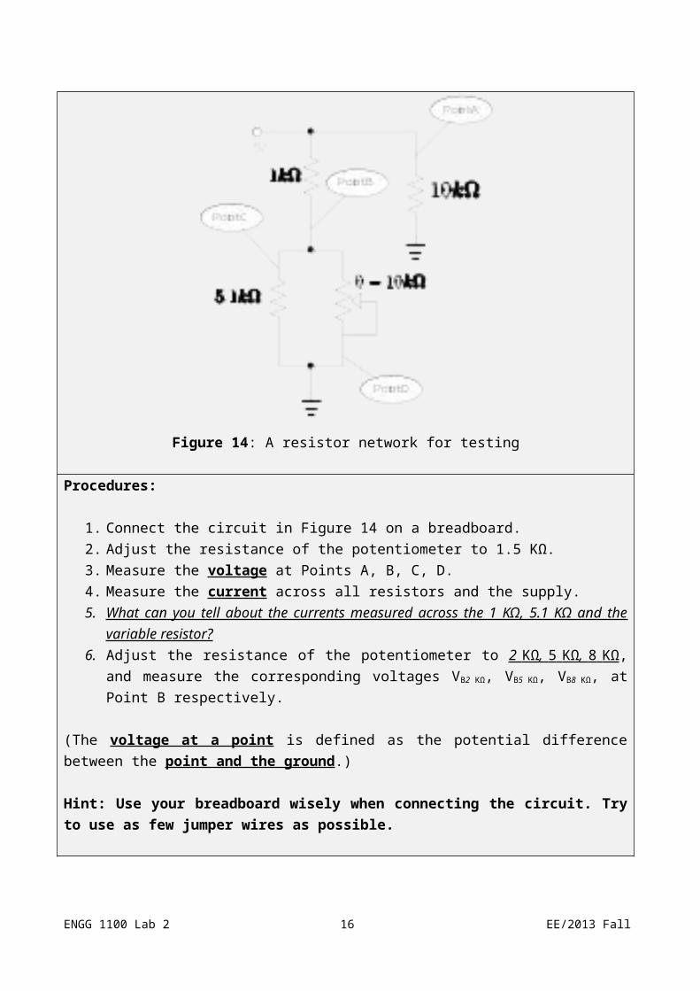
Figure 14: A resistor network for testing
Procedures:
ENGG 1100 Lab 2 14 EE/2013 Fall
1. Connect the circuit in Figure 14 on a breadboard.2. Adjust the resistance of the potentiometer to 1.5 KΩ.3. Measure the voltage at Points A, B, C, D.4. Measure the current across all resistors and the supply.5. What can you tell about the currents measured across the 1 KΩ, 5.1 KΩ and the variable
resistor?6. Adjust the resistance of the potentiometer to 2 KΩ , 5 KΩ , 8 KΩ , and measure the
corresponding voltages VB2 KΩ, VB5 KΩ, VB8 KΩ, at Point B respectively.
(The voltage at a point is defined as the potential difference between the point and the ground.)
Hint: Use your breadboard wisely when connecting the circuit. Try to use as few jumper wires as possible.
Appendix
A.1. Component Symbols
Some popularly seen electronic components and symbols are shown below:
Figure 17: Electronic symbols
ENGG 1100 Lab 2 15 EE/2013 Fall
Resistor (R): A resistor is a two-terminal electronic component which is governed by Ohm’s law, which states that the voltage across two terminals of the resistor is proportional to the electric current through it. The resistance of a resistor is measured in Ohms, or, symbolically, .
Capacitor (C): A capacitor consists of a pair of conductors separated by an insulator. When a potential difference exists between the two conductors, an electric field presents in the insulator and energy is stored. The capacitance of a capacitor is measured in Farads, or, symbolically, F.
Inductor (L): An inductor is a passive electrical component usually in the shape of a coil. It can store energy in a magnetic field created by the electric current passing through it. The inductance of an inductor is measured in Henry, or, symbolically, H.
Diode: A diode is a two-terminal semiconductor device whose conducting properties are different in the two possible directions of the current. To be specific, a diode conducts electric current in only one direction.
Transistor: A transistor is a three-terminal semiconductor device which is used to amplify or switch electronic signals. Transistors play a very important role to electronics.
ENGG 1100 Lab 2 16 EE/2013 Fall


![[PPT]VHDL 3 Finite State Machines FSM - Chinese University …khwong/www2/ceng3430/vhdl5.pptx · Web viewVHDL 5FINITE STATE MACHINES (FSM) Some pictures are obtained from FPGA Express](https://img.pdfslide.us/doc/110x75/5b2b9a7b7f8b9a594c8b6a58/pptvhdl-3-finite-state-machines-fsm-chinese-university-khwongwww2ceng3430vhdl5pptx.jpg)


![Resolution Improvement from Stereo Images with 3D Pose ...khwong/c2006_icip06_Resolution... · to ungrade a sequence of real images 2. Theory In the formulation of Irani and Peleg[8]](https://img.pdfslide.us/doc/110x75/5fd657fc13a86761485325bb/resolution-improvement-from-stereo-images-with-3d-pose-khwongc2006icip06resolution.jpg)