Embed Size (px)
Citation preview
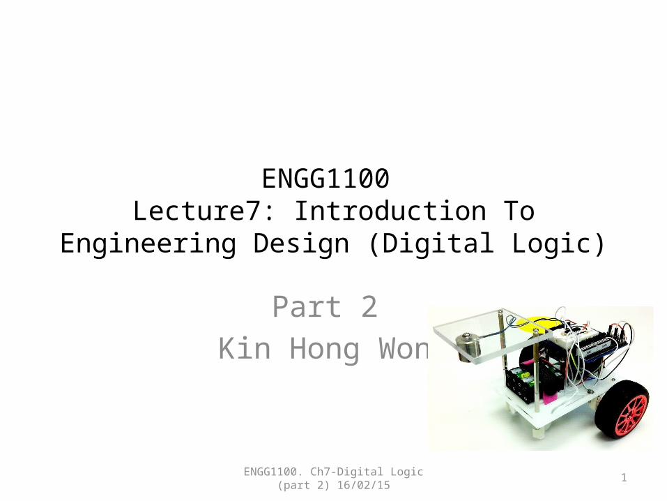
ENGG1100 Lecture7: Introduction To Engineering Design
(Digital Logic)
Part 2 Kin Hong Wong
ENGG1100. Ch7-Digital Logic (part 2) 16/02/15 1

Intro. | Robot | If-Then-Else | Switch-case | FSM | no sensor | 2 sensors | 3 sensors
Overview• Part 1 (late week): Introduction
– 1.1 What is Digital logic?– 1.2 Digital operations (AND, OR, NOT)– 1.3 Truth table– 1.4 Robot Hardware– 1.5 Software implement of digital operations
• Part 2 : Hardware/software Implementation– 2.1 Robot system– 2.1 Use of If-then-else (software method 1)– 2.2 Use of switch case (software method 2)– 2.3 Finite state machines
ENGG1100. Ch7-Digital Logic (part 2) 16/02/15 2

Intro. | Robot | If-Then-Else | Switch-case | FSM | no sensor | 2 sensors | 3 sensors
2.1 The Intelligent Robot system
•
ENGG1100. Ch7-Digital Logic (part 2) 16/02/15
3
Arduino board(programs to be run in the Arduino computer)::Loop{ If …. then…. else….}
In1In2In3In4
Out1Out2Out3Out4
Motor drivers
Magnetic sensorsS1, S2
Magnetic strips
S2 S1
RM1RM2
LM1LM2
Our debug interfaceBoard
Programmer to update the program
USB cable
L293DH-bridge

Intro. | Robot | If-Then-Else | Switch-case | FSM | no sensor | 2 sensors | 3 sensors
Our debug (interface) board• You may use the debug board provided to
connect input/output signals to the Arduino board
ENGG1100. Ch7-Digital Logic (part 2) 16/02/15 4
Intro. | Robot | If-Then-Else | Switch-case | FSM | no sensor | 2 sensors | 3 sensors
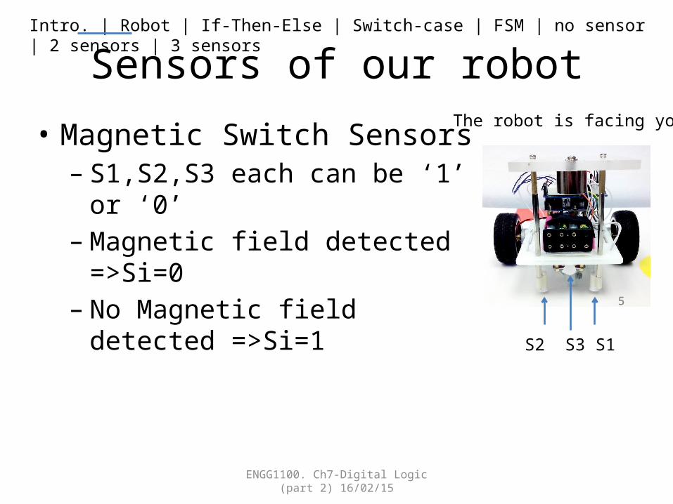
Sensors of our robot
• Magnetic Switch Sensors– S1,S2,S3 each can be ‘1’ or ‘0’– Magnetic field detected =>Si=0– No Magnetic field detected =>Si=1
ENGG1100. Ch7-Digital Logic (part 2) 16/02/15
55
S2 S3 S1
The robot is facing you

Intro. | Robot | If-Then-Else | Switch-case | FSM | no sensor | 2 sensors | 3 sensors
Motors of our robot• Motors: LM1, LM2, RM1 and RM2
– Instruction LM1(0) sets LM1 to be 0– Instruction LM1(1) sets LM1 to be 1
• Motor control method– {LM1=1 and LM2=0}=> Left-motor moves forward – {LM1=0 and LM2=1} => Left-motor moves backward – {LM1=0 and LM2=0} => Left-motor stops– Similar for the right-motor
ENGG1100. Ch7-Digital Logic (part 2) 16/02/15 66
RM1RM2
LM1LM2
The robot is facing you
Intro. | Robot | If-Then-Else | Switch-case | FSM | no sensor | 2 sensors | 3 sensors
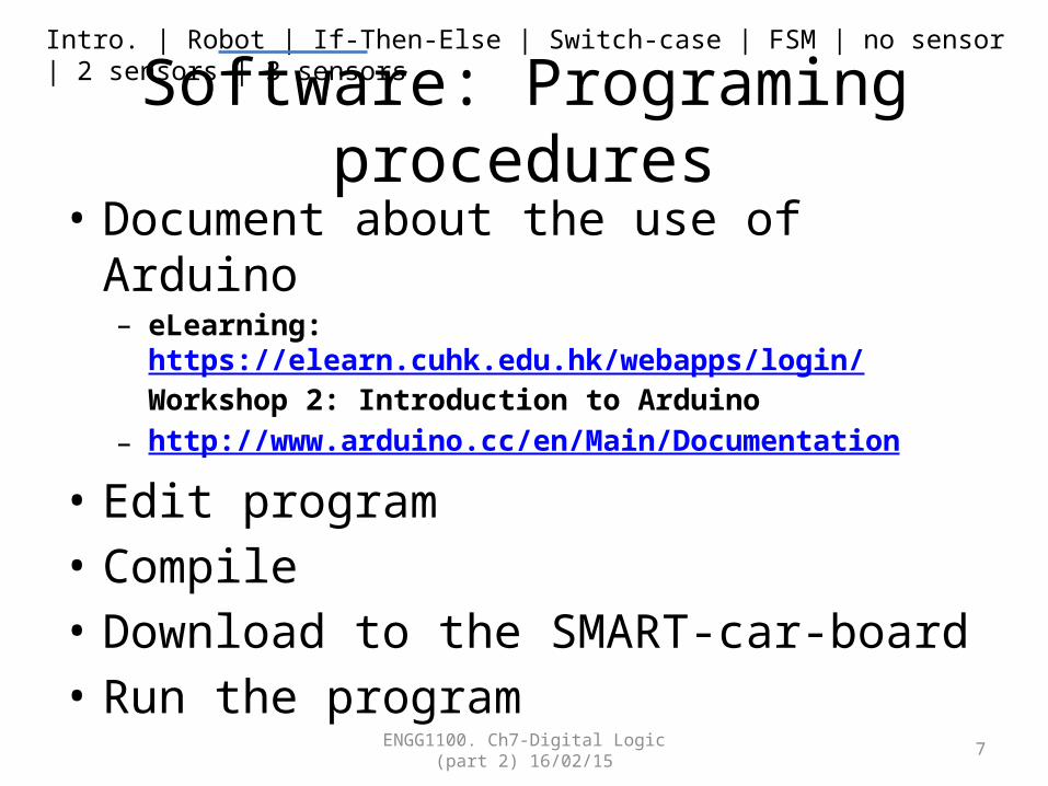
Software: Programing procedures• Document about the use of Arduino
– eLearning: https://elearn.cuhk.edu.hk/webapps/login/Workshop 2: Introduction to Arduino
– http://www.arduino.cc/en/Main/Documentation
• Edit program• Compile• Download to the SMART-car-board• Run the program
ENGG1100. Ch7-Digital Logic (part 2) 16/02/15 7
Intro. | Robot | If-Then-Else | Switch-case | FSM | no sensor | 2 sensors | 3 sensors
2.2 Method 1: to implement logic operations in a program
usingLogic Formula (use of IF-Then-Else)
ENGG1100. Ch7-Digital Logic (part 2) 16/02/15 8
Intro. | Robot | If-Then-Else | Switch-case | FSM | no sensor | 2 sensors | 3 sensors
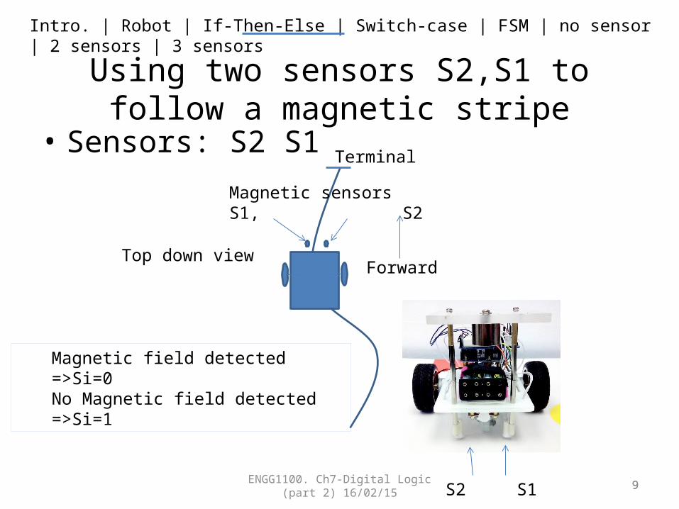
Using two sensors S2,S1 to follow a magnetic stripe
• Sensors: S2 S1
ENGG1100. Ch7-Digital Logic (part 2) 16/02/15 9
Magnetic sensorsS1, S2
Terminal
9S2 S1
Magnetic field detected =>Si=0No Magnetic field detected =>Si=1
Top down viewForward

Intro. | Robot | If-Then-Else | Switch-case | FSM | no sensor | 2 sensors | 3 sensors
Method 1 (Use of If-then-else): This program will enable the robot to follow the magnetic path
• The program segment:• Void loop()• {• LM1(0);LM2(0);RM1(0);RM2(0);
• //comment :LM1 =S1 AND S2• If (S1()==1 && S2()==1) LM1(1);• Else LM1(0);
• //comment :LM2 = S1 OR S2• If (S1()==1 || S2()==1) LM2(1);• Else LM2(0);
• }
• Notations used in the program• Void Loop ( )= repeated the execution of the
lines inside { } • LM1(0) sets the digital output LM1 to 0• LM1(1) sets the digital output LM1 to 1• == means condition• && means logic operation AND• || means logic operation OR• ! means logic operation NOT• //comment, for you to put in your own notes
ENGG1100. Ch7-Digital Logic (part 2) 16/02/15 10
S2 S1
RM1RM2
LM1LM2
You may need to write S1(),S2(),LM1(),LM2(), etc. for your own system

Intro. | Robot | If-Then-Else | Switch-case | FSM | no sensor | 2 sensors | 3 sensors
2.2 Software Method 2 : to implement logic operation in
a program using truth table (Use of Switch-Case)
ENGG1100. Ch7-Digital Logic (part 2) 16/02/15 11
Intro. | Robot | If-Then-Else | Switch-case | FSM | no sensor | 2 sensors | 3 sensors
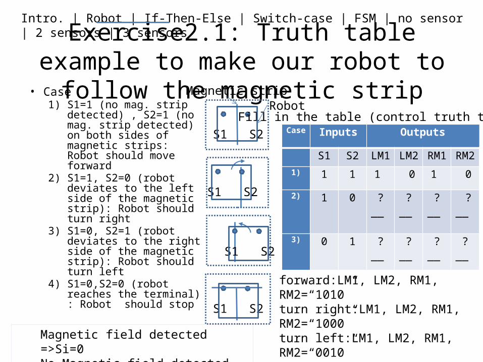
Exercise2.1: Truth table example to make our robot to follow the magnetic strip
• Case1) S1=1 (no mag. strip
detected) , S2=1 (no mag. strip detected) on both sides of magnetic strips: Robot should move forward
2) S1=1, S2=0 (robot deviates to the left side of the magnetic strip): Robot should turn right
3) S1=0, S2=1 (robot deviates to the right side of the magnetic strip): Robot should turn left
4) S1=0,S2=0 (robot reaches the terminal) : Robot should stop
ENGG1100. Ch7-Digital Logic (part 2) 16/02/15 12
Case Inputs Outputs
S1 S2 LM1 LM2 RM1 RM2
1) 1 1 1 0 1 0
2) 1 0 ?__ ?__ ?__ ?__
3) 0 1 ?__ ?__ ?__ ?__
4) 0 0 ?__
?__
?__
?__
Magnetic strip
S1 S2
S1 S2
S1 S2
forward:LM1, LM2, RM1, RM2=“1010”turn right:LM1, LM2, RM1, RM2=“1000”turn left:LM1, LM2, RM1, RM2=“0010”S1 S2
Fill in the table (control truth table)Robot
Magnetic field detected =>Si=0No Magnetic field detected =>Si=1

Intro. | Robot | If-Then-Else | Switch-case | FSM | no sensor | 2 sensors | 3 sensors
After the truth table is obtained we will use “Switch – case” in a program to implement it
• You may treat it as a table lookup method• In English it means:
– If INPUT is code1, result 1 will occur– If INPUT is code2, result 2 will occur– If INPUT is code3, result 3 will occur– Etc……
• switch (INPUT) • {• case code1 : result 1;• break;
• case code2 : result 2;• break;
• case code3 : result 3;• break;• :• }
ENGG1100. Ch7-Digital Logic (part 2) 16/02/15 13
Code_i=inputs for row i of a truth table Result_i=output for row i of a truth table
Intro. | Robot | If-Then-Else | Switch-case | FSM | no sensor | 2 sensors | 3 sensors
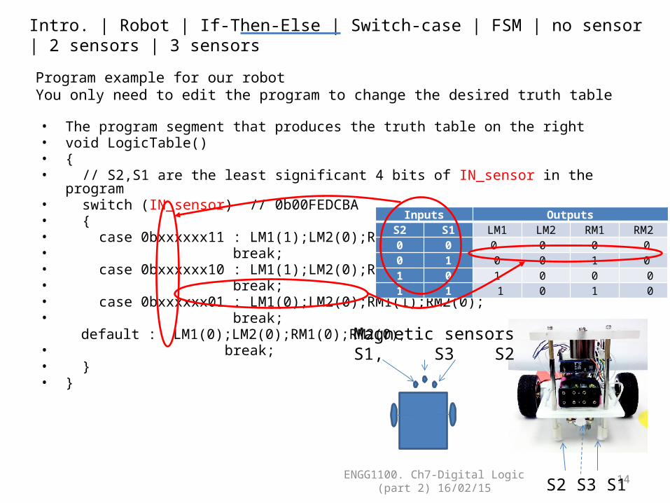
Program example for our robotYou only need to edit the program to change the desired truth table • The program segment that produces the truth table on the right• void LogicTable()• {• // S2,S1 are the least significant 4 bits of IN_sensor in the program• switch (IN_sensor) // 0b00FEDCBA• {• case 0bxxxxxx11 : LM1(1);LM2(0);RM1(1);RM2(0);• break;• case 0bxxxxxx10 : LM1(1);LM2(0);RM1(0);RM2(0);• break;• case 0bxxxxxx01 : LM1(0);LM2(0);RM1(1);RM2(0);• break;
default : LM1(0);LM2(0);RM1(0);RM2(0);• break;• } • }
ENGG1100. Ch7-Digital Logic (part 2) 16/02/15
14
Inputs OutputsS2 S1 LM1 LM2 RM1 RM20 0 0 0 0 00 1 0 0 1 01 0 1 0 0 0 1 1 1 0 1 0
Magnetic sensorsS1, S3 S2
S2 S3 S1

Intro. | Robot | If-Then-Else | Switch-case | FSM | no sensor | 2 sensors | 3 sensors
2.3 Introduction to Finite State Machines
• We will have three examples here:a) Simple finite state machine (no sensor). E.g.: The
dancing robotb) An finite state machine uses 2 sensors. E.g. The
robot that follows the magnetic stripc) An finite state machine uses 3 sensors. E.g. The
robot that follows the magnetic strip, and stops when it detects a magnet in the front.
ENGG1100. Ch7-Digital Logic (part 2) 16/02/15 15
Intro. | Robot | If-Then-Else | Switch-case | FSM | no sensor | 2 sensors | 3 sensors
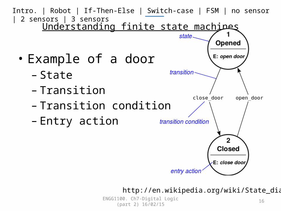
Understanding finite state machines
• Example of a door– State– Transition– Transition condition– Entry action
ENGG1100. Ch7-Digital Logic (part 2) 16/02/15 16
http://en.wikipedia.org/wiki/State_diagram
Intro. | Robot | If-Then-Else | Switch-case | FSM | no sensor | 2 sensors | 3 sensors
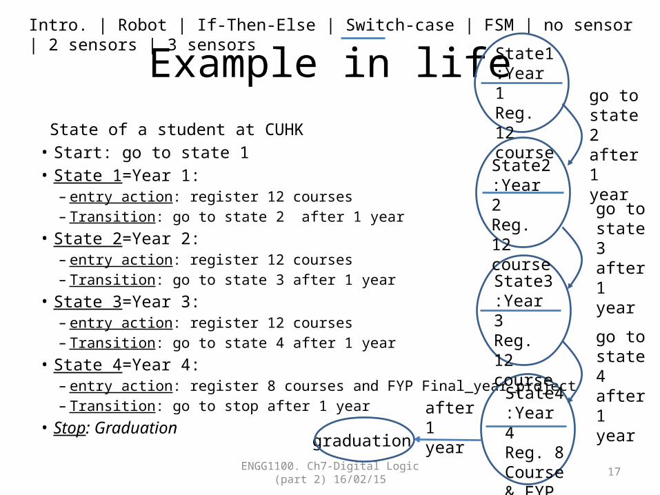
Example in life State of a student at CUHK• Start: go to state 1• State 1=Year 1:
– entry action: register 12 courses– Transition: go to state 2 after 1 year
• State 2=Year 2:– entry action: register 12 courses– Transition: go to state 3 after 1 year
• State 3=Year 3:– entry action: register 12 courses– Transition: go to state 4 after 1 year
• State 4=Year 4:– entry action: register 8 courses and FYP Final_year_project– Transition: go to stop after 1 year
• Stop: GraduationENGG1100. Ch7-Digital Logic (part 2)
16/02/15 17
State1:Year 1Reg. 12course
go to state 2 after 1 year
go to state 3 after 1 year
go to state 4 after 1 year
graduation
State2:Year 2Reg. 12course
State3:Year 3Reg. 12course
State4:Year 4Reg. 8Course & FYP
after 1 year

Intro. | Robot | If-Then-Else | Switch-case | FSM | no sensor | 2 sensors | 3 sensors
2.3a) The simple state machine (no transition condition )
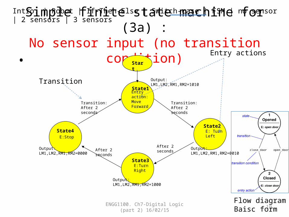
• The robot that dances with a pattern– Forward 2 seconds, turn left 2 seconds and turn
right 2 seconds, stop and repeat the pattern again• Video demo:• http://youtu.be/iyakbVyoafI
ENGG1100. Ch7-Digital Logic (part 2) 16/02/15 18
Intro. | Robot | If-Then-Else | Switch-case | FSM | no sensor | 2 sensors | 3 sensors
Simple finite state machine for (3a) :No sensor input (no transition condition)
•
ENGG1100. Ch7-Digital Logic (part 2) 16/02/15 19
Entry action:MoveForward
Output: LM1,LM2,RM1,RM2=1010
E: TurnLeft
Output: LM1,LM2,RM1,RM2=0010
E:TurnRight
Output: LM1,LM2,RM1,RM2=1000
Transition: After 2 seconds
E:Stop
Output: LM1,LM2,RM1,RM2=0000
After 2 secondsAfter 2 seconds
Transition: After 2 seconds
State1
State2
State3
State4
Start
Entry actions
Transition
Flow diagramBaisc form

Intro. | Robot | If-Then-Else | Switch-case | FSM | no sensor | 2 sensors | 3 sensors
Implementation of the finite state machine for (3a)
• Part of the sample source code is shown below:• switch(state)• {• case STATE1:• LM1=1;LM2=0;RM1=1;RM2=0;SPEED=200; //entry action• DELAY_TIME=2000; // transition :delay 2 seconds • motors(LM1,LM2,RM1,RM2,SPEED,SPEED,DELAY_TIME); • state=STATE2; // next state will be state2• break; //end of the current state• case STATE2:• LM1=0;LM2=0;RM1=1;RM2=0;SPEED=200;DELAY_TIME=2000; // delay 2 seconds• motors(LM1,LM2,RM1,RM2,SPEED,SPEED,DELAY_TIME);• state=STATE3; //next state will be state3• break; //end of the current state• // to be continued on next page
ENGG1100. Ch7-Digital Logic (part 2) 16/02/15 20
Use of DELAY:DELAY_TIME=2000motors(LM1,LM2,RM1,RM2,SPEED,SPEED,DELAY_TIME);
Set motor to run forward with speed=200
Exercise: explain the meaning of state 2
You may need to write the function motors( ) for your project

Intro. | Robot | If-Then-Else | Switch-case | FSM | no sensor | 2 sensors | 3 sensors
Continue from last pageExercise 2.2
• case STATE3:• (fill in by students)
• break; • case STATE4:• (fill in by students)
• break;• default: //none of above will be forced to run state4• state=STATE4;• break;• } ENGG1100. Ch7-Digital Logic (part 2)
16/02/15 21
Exercise2.2: Fill in the missing programs in state 3 and 4

Intro. | Robot | If-Then-Else | Switch-case | FSM | no sensor | 2 sensors | 3 sensors
2.3b) A finite state machine uses 2 sensors(with transition condition)
• E.g. The robot that follows the magnetic strip
ENGG1100. Ch7-Digital Logic (part 2) 16/02/15 22
Intro. | Robot | If-Then-Else | Switch-case | FSM | no sensor | 2 sensors | 3 sensors
Example in life(with transition condition : study hard)
State of a student at CUHK• Start:go to state1• State 1=Year 1:
– entry action: register 12 courses– Transition: if (study hard) promote to state2 (year2) else go back to state 1
• State 2=Year 2:– entry action: register 12 courses– Transition: if (study hard) promote to state3 (year3) else go back to state 2
• State 3=Year 3:– entry action: register 12 courses– Transition: if (study hard) promote to state4 (year4) else go back to state 3
• State 4=Year 4:– entry action: register 12 courses– Transition: if (study hard) promote to stop(graduation) else back go to state4
• Stop: Graduation
ENGG1100. Ch7-Digital Logic (part 2) 16/02/15 23
Intro. | Robot | If-Then-Else | Switch-case | FSM | no sensor | 2 sensors | 3 sensors
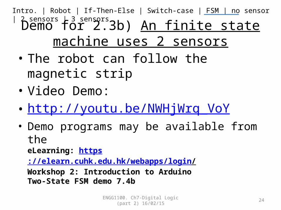
Demo for 2.3b) An finite state machine uses 2 sensors
• The robot can follow the magnetic strip• Video Demo:• http://youtu.be/NWHjWrq_VoY• Demo programs may be available from the
eLearning: https://elearn.cuhk.edu.hk/webapps/login/ Workshop 2: Introduction to ArduinoTwo-State FSM demo 7.4b
ENGG1100. Ch7-Digital Logic (part 2) 16/02/15 24

Intro. | Robot | If-Then-Else | Switch-case | FSM | no sensor | 2 sensors | 3 sensors
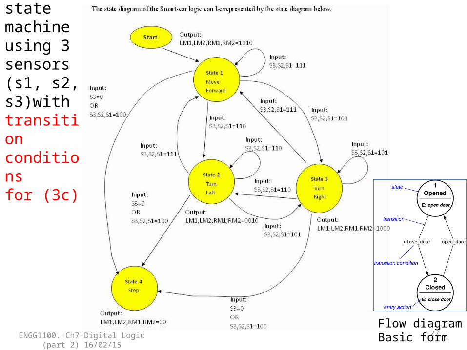
2.3c) Add another sensor at the front to detect the target object
• Sensors: S2, S1 are facing the ground to detect the magnetic stripe
• S3 is facing the front, used to detect the target object– S3=1 if no object is detected– S3=0 if an object is detected
ENGG1100. Ch7-Digital Logic (part 2) 16/02/15 25
Magnetic sensorsS1, S3 S2
25S2 S3 S1

Intro. | Robot | If-Then-Else | Switch-case | FSM | no sensor | 2 sensors | 3 sensors
A finite state machine uses 3 sensorsE.g. Follow the magnetic strip, find the CAN and stop
• Video Demo : http://youtu.be/JEQkuax7lKE– The robot finds the CAN using the magnetic strip
placed under the testing board and stops
ENGG1100. Ch7-Digital Logic (part 2) 16/02/15 26
S2
S3
S1Obstacle
End point
RM1,RM2
LM1,LM2
Start point
ENGG1100. Ch7-Digital Logic (part 2) 16/02/15
27
Finite state machine using 3 sensors (s1, s2, s3)with transition conditionsfor (3c)
Flow diagramBasic form
Intro. | Robot | If-Then-Else | Switch-case | FSM | no sensor | 2 sensors | 3 sensors
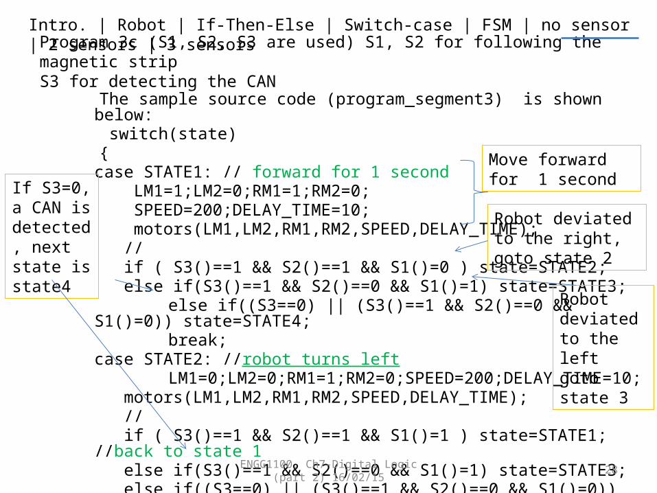
Program 3c (S1, S2, S3 are used) S1, S2 for following the magnetic stripS3 for detecting the CAN
The sample source code (program_segment3) is shown below: switch(state) {
case STATE1: // forward for 1 second LM1=1;LM2=0;RM1=1;RM2=0; SPEED=200;DELAY_TIME=10; motors(LM1,LM2,RM1,RM2,SPEED,DELAY_TIME); // if ( S3()==1 && S2()==1 && S1()=0 ) state=STATE2; else if(S3()==1 && S2()==0 && S1()=1) state=STATE3;
else if((S3==0) || (S3()==1 && S2()==0 && S1()=0)) state=STATE4; break;
case STATE2: //robot turns left LM1=0;LM2=0;RM1=1;RM2=0;SPEED=200;DELAY_TIME=10;
motors(LM1,LM2,RM1,RM2,SPEED,DELAY_TIME); // if ( S3()==1 && S2()==1 && S1()=1 ) state=STATE1; //back to state 1 else if(S3()==1 && S2()==0 && S1()=1) state=STATE3; else if((S3==0) || (S3()==1 && S2()==0 && S1()=0)) state=STATE4; break; ENGG1100. Ch7-Digital Logic (part 2)
16/02/15 28
If S3=0, a CAN is detected, next state is state4
Move forward for 1 second
Robot deviated to the right, goto state 2
Robot deviated to the leftgoto state 3

Intro. | Robot | If-Then-Else | Switch-case | FSM | no sensor | 2 sensors | 3 sensors
• case STATE3: //robot turns right• // To be filled by students as an exercise
• case STATE4: //stop• // To be filled by students as an exercise
• default: //none of above states• state=STATE4; LM1=0;LM2=0;RM1=0;RM2=0;• SPEED=200;DELAY_TIME=10;• motors(LM1,LM2,RM1,RM2,SPEED,DELAY_TIME);• break;• }
ENGG1100. Ch7-Digital Logic (part 2) 16/02/15 29
Intro. | Robot | If-Then-Else | Switch-case | FSM | no sensor | 2 sensors | 3 sensors
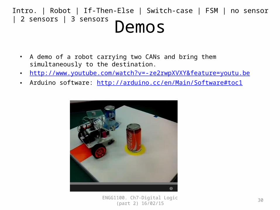
Demos• A demo of a robot carrying two CANs and bring them simultaneously to the destination.• http://www.youtube.com/watch?v=-ze2rwpXVXY&feature=youtu.be• Arduino software: http://arduino.cc/en/Main/Software#toc1
ENGG1100. Ch7-Digital Logic (part 2) 16/02/15 30
Overall summary
• In digital logic part 1 and 2, we learned– What is digital logic– Digital logic operations represented by
• Digital logic formula method• Truth table method• Their implementation methods using programs
– Finite state machines • Theory and implementations
– Use the above to control a robot for specific tasks
ENGG1100. Ch7-Digital Logic (part 2) 16/02/15 31

End
ENGG1100. Ch7-Digital Logic (part 2) 16/02/15 32
ENGG1100. Ch7-Digital Logic (part 2) 16/02/15
33
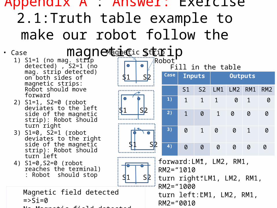
Appendix A : Answer: Exercise 2.1:Truth table example to make our robot follow
the magnetic strip• Case
1) S1=1 (no mag. strip detected) , S2=1 (no mag. strip detected) on both sides of magnetic strips: Robot should move forward
2) S1=1, S2=0 (robot deviates to the left side of the magnetic strip): Robot should turn right
3) S1=0, S2=1 (robot deviates to the right side of the magnetic strip): Robot should turn left
4) S1=0,S2=0 (robot reaches the terminal) : Robot should stop
Case Inputs Outputs
S1 S2 LM1 LM2 RM1 RM2
1) 1 1 1 0 1 0
2) 1 0 1 0 0 0
3) 0 1 0 0 1 0
4) 0 0 0
0
0
0
Magnetic strip
S1 S2
S1 S2
S1 S2
forward:LM1, LM2, RM1, RM2=“1010”turn right:LM1, LM2, RM1, RM2=“1000”turn left:LM1, LM2, RM1, RM2=“0010”S1 S2
Fill in the tableRobot
Magnetic field detected =>Si=0No Magnetic field detected =>Si=1

Appendix B: Answer for Ex2.3
• case STATE3:• LM1=1;LM2=0;RM1=0;RM2=0;DELAY_TIME=2000; • motors(LM1,LM2,RM1,RM2,SPEED,SPEED,DELAY_TIME);• state=STATE4;• break; • case STATE4:• LM1=0;LM2=0;RM1=0;RM2=0;SPEED=200;DELAY_TIME=2000; • motors(LM1,LM2,RM1,RM2,SPEED,SPEED,DELAY_TIME);• state=STATE1;• break;• default: //none of above will be forced to run state4• state=STATE4;• break;• } ENGG1100. Ch7-Digital Logic (part 2)
16/02/15 34
Exercises: explain the meaning of state 3 and 4