Embed Size (px)
Citation preview
Installation and Operation Manual
KILOMUX-2100 MODULE
KHS.U ISDN "U" Interface Data Module

KHS.U ISDN "U" Interface Data Module
Installation and Operation Manual
Notice This manual contains information that is proprietary to RAD Data Communications Ltd. ("RAD"). No part of this publication may be reproduced in any form whatsoever without prior written approval by RAD Data Communications.
Right, title and interest, all information, copyrights, patents, know-how, trade secrets and other intellectual property or other proprietary rights relating to this manual and to the KHS.U and any software components contained therein are proprietary products of RAD protected under international copyright law and shall be and remain solely with RAD.
KHS.U is a registered trademark of RAD. No right, license, or interest to such trademark is granted hereunder, and you agree that no such right, license, or interest shall be asserted by you with respect to such trademark.
You shall not copy, reverse compile or reverse assemble all or any portion of the Manual or the KHS.U. You are prohibited from, and shall not, directly or indirectly, develop, market, distribute, license, or sell any product that supports substantially similar functionality as the KHS.U, based on or derived in any way from the KHS.U. Your undertaking in this paragraph shall survive the termination of this Agreement.
This Agreement is effective upon your opening of the KHS.U package and shall continue until terminated. RAD may terminate this Agreement upon the breach by you of any term hereof. Upon such termination by RAD, you agree to return to RAD the KHS.U and all copies and portions thereof.
For further information contact RAD at the address below or contact your local distributor.
International Headquarters RAD Data Communications Ltd. 24 Raoul Wallenberg St. Tel Aviv 69719 Israel Tel: 972-3-6458181 Fax: 972-3-6498250 E-mail: [email protected]
North America Headquarters RAD Data Communications Inc. 900 Corporate Drive Mahwah, NJ 07430 USA Tel: (201) 529-1100, Toll free: 1-800-444-7234 Fax: (201) 529-5777 E-mail: [email protected]
© 1988–2006 RAD Data Communications Ltd. Publication No. 420-212-05/06

KHS.U Module Channels Configuration Procedure 1
Quick Start Guide If you are familiar with the KHS.U module, use this guide to prepare it for operation.
The KHS.U module contains components sensitive to electrostatic discharge (ESD). To prevent ESD damage, always hold the module by its sides, and do not touch the module components or connectors.
1. Connecting the Cables
To connect the KHS.U module interface:
• Insert the module into the assigned I/O slot and connect the cables as follows: Connect the DC Power cable to the DC PWR-IN socket for external
phantom feed voltage. Connect the Channel cable to the corresponding channel.
2. KHS.U Module Channels Configuration Procedure
Start the configuration of a specific channel of a KHS.U module by typing the command DEF CH i:j <Enter>, where i is the number of the module slot (1 through 12 for KM-2100 or 1 through 4 for KM-2104) and j is the desired B channel (1 or 2 for KHS.U/S).
The channel configuration parameters and their allowed range of values are listed below.
Caution
Quick Start Guide KHS.U Installation and Operation Manual
2 KHS.U Module Channels Configuration Procedure
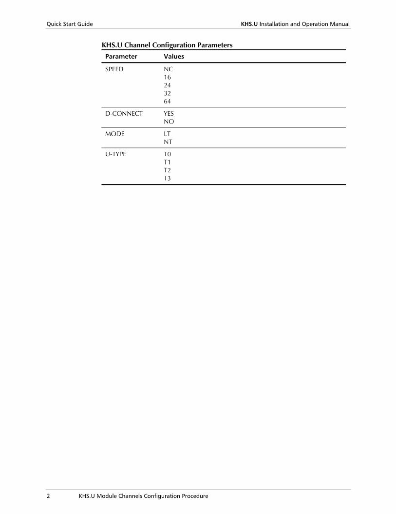
KHS.U Channel Configuration Parameters
Parameter Values
SPEED NC 16 24 32 64
D-CONNECT YES NO
MODE LT NT
U-TYPE T0 T1 T2 T3
KHS.U Installation and Operation Manual i
Contents
Chapter 1. Introduction 1.1 Overview..................................................................................................................... 1-1
Versions................................................................................................................................1-1 Applications..........................................................................................................................1-1 Features................................................................................................................................1-2
1.2 Technical Specifications............................................................................................... 1-4
Chapter 2. Module Installation and Operation 2.1 Scope .......................................................................................................................... 2-1 2.2 Module Installation ...................................................................................................... 2-1
Module Panels......................................................................................................................2-1 Setting the Internal Jumpers ..................................................................................................2-2 Installing a KHS.U Module ....................................................................................................2-3 Connecting the Cables ..........................................................................................................2-4 Connecting the Phantom Feed Voltage..................................................................................2-4
2.3 Normal Indications ...................................................................................................... 2-4 2.4 Configuring KHS.U via the Front Panel ........................................................................ 2-5
Configuring Channel Parameters ...........................................................................................2-5
Chapter 3. Configuration via Supervision Terminal 3.1 Introduction................................................................................................................. 3-1 3.2 Outline of Configuration Procedure ............................................................................. 3-1 3.3 Configuring KHS.U ...................................................................................................... 3-2
Inclusion of KHS.U in Database ............................................................................................3-2 Configuring the KHS.U Channel............................................................................................3-3
Chapter 4. Alarms and Diagnostics 4.1 Introduction................................................................................................................. 4-1 4.2 Diagnostic Functions.................................................................................................... 4-1
Local Loopback ....................................................................................................................4-1 Remote Loopback.................................................................................................................4-2 Recommended Test Sequence..............................................................................................4-2
4.3 Alarm Messages ........................................................................................................... 4-3 4.4 Technical Support........................................................................................................ 4-4
Appendix A. Connection Data

Table of Contents
ii KHS.U Installation and Operation Manual
Overview 1-1
Chapter 1 Introduction
1.1 Overview
The KHS.U module is a data interface module for the Kilomux Modular High-Speed TDM Multiplexer Systems that enable the extension of ISDN lines over non-ISDN facilities. The KHS.U module provides a "U" ISDN basic rate access interface, which can be configured to operate as LT (line termination) or NT (network termination).
The "U" interface carries two B channels (64 kbps each) and one D channel (16 kbps). The user can individually configure each B channel to support payload data rates of 16, 32, and 64 kbps. Each channel can be independently connected to the Kilomux main link. Therefore, the user needs allocate main link bandwidth only in accordance with the actual payload carried by the module channels. The KHS.U modules can operate over main link data rates, up to 768 kbps; the minimum main link data rate depends on the actual payload carried by the modules installed in the Kilomux enclosure.
Versions The KHS.U module is available with one "U" interface
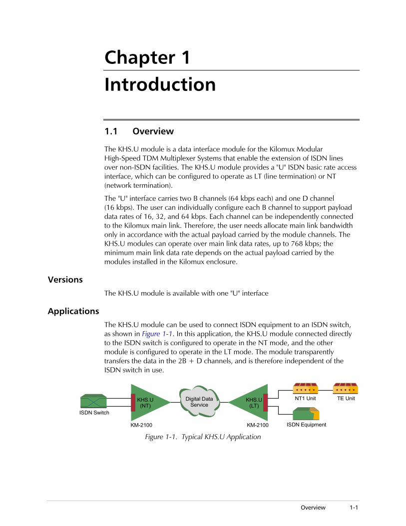
Applications The KHS.U module can be used to connect ISDN equipment to an ISDN switch, as shown in Figure 1-1. In this application, the KHS.U module connected directly to the ISDN switch is configured to operate in the NT mode, and the other module is configured to operate in the LT mode. The module transparently transfers the data in the 2B + D channels, and is therefore independent of the ISDN switch in use.
Digital DataService
KM-2100 KM-2100 ISDN Equipment
NT1 Unit TE UnitKHS.U(NT)
KHS.U(LT)
ISDN Switch
Figure 1-1. Typical KHS.U Application
Chapter 1 Introduction KHS.U Installation and Operation Manual
1-2 Overview
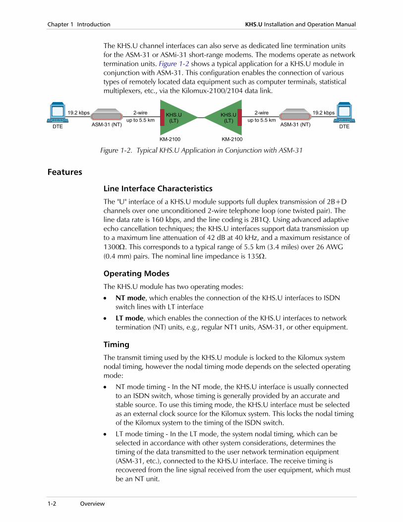
The KHS.U channel interfaces can also serve as dedicated line termination units for the ASM-31 or ASMi-31 short-range modems. The modems operate as network termination units. Figure 1-2 shows a typical application for a KHS.U module in conjunction with ASM-31. This configuration enables the connection of various types of remotely located data equipment such as computer terminals, statistical multiplexers, etc., via the Kilomux-2100/2104 data link.
ASM-31 (NT)
KM-2100
DTE
2-wire19.2 kbpsup to 5.5 km
KHS.U(LT)
ASM-31 (NT)
KM-2100
DTE
2-wire 19.2 kbpsup to 5.5 km
KHS.U(LT)
Figure 1-2. Typical KHS.U Application in Conjunction with ASM-31
Features
Line Interface Characteristics
The "U" interface of a KHS.U module supports full duplex transmission of 2B+D channels over one unconditioned 2-wire telephone loop (one twisted pair). The line data rate is 160 kbps, and the line coding is 2B1Q. Using advanced adaptive echo cancellation techniques; the KHS.U interfaces support data transmission up to a maximum line attenuation of 42 dB at 40 kHz, and a maximum resistance of 1300Ω. This corresponds to a typical range of 5.5 km (3.4 miles) over 26 AWG (0.4 mm) pairs. The nominal line impedance is 135Ω.
Operating Modes
The KHS.U module has two operating modes:
• NT mode, which enables the connection of the KHS.U interfaces to ISDN switch lines with LT interface
• LT mode, which enables the connection of the KHS.U interfaces to network termination (NT) units, e.g., regular NT1 units, ASM-31, or other equipment.
Timing
The transmit timing used by the KHS.U module is locked to the Kilomux system nodal timing, however the nodal timing mode depends on the selected operating mode:
• NT mode timing - In the NT mode, the KHS.U interface is usually connected to an ISDN switch, whose timing is generally provided by an accurate and stable source. To use this timing mode, the KHS.U interface must be selected as an external clock source for the Kilomux system. This locks the nodal timing of the Kilomux system to the timing of the ISDN switch.
• LT mode timing - In the LT mode, the system nodal timing, which can be selected in accordance with other system considerations, determines the timing of the data transmitted to the user network termination equipment (ASM-31, etc.), connected to the KHS.U interface. The receive timing is recovered from the line signal received from the user equipment, which must be an NT unit.
KHS.U Installation and Operation Manual Chapter 1 Introduction
Technical Specifications 1-3
Main Link Bandwidth Requirements
The KHS.U module enables controlling the bandwidth occupied on the main link by each individual ISDN channel. Therefore, the user can connect only the required channels of each interface; when the B channels are used at rates lower than their nominal (64 kbps) rate, e.g., 16 kbps or 32 kbps, the module requires main link bandwidth equal to the actual payload data rate.
Phantom Feed Function
The KHS.U modules can provide power to equipment at the remote end of the line connected to the port, using the phantom feeding method. To produce the phantom feeding power, KHS.U uses an external power source. The external DC source, for example Ringer-2000 unit or KM-Ringer module, is connected directly to the KHS.U module via its external DC PWR-IN connector.
KHS.U produces the phantom feed voltage by combining the standard Ringer feed voltage output (-24 VDC or -48 VDC) with the internal +12 VDC supplied by the Kilomux chassis. Since the maximum allowed input voltage for KHS.U is 48 VDC, the maximum resulting phantom feed voltage provided by the module cannot exceed 60 VDC. Refer to Connecting the Phantom Feed Voltage in Chapter 2 for details on the KHS.U phantom feed functions.
Configuration, Diagnostics and Management
All the module-operating parameters, except for the operating mode (LT or NT), are controlled via the Kilomux supervisory port.
The KHS.U module supports self-diagnostics upon power-up, as well as test loopbacks controlled by means of the system management functions, thereby reducing downtime to minimum. Test loopbacks can be individually activated on each module interface, and include local loopback and remote loopback. When downloading is enabled, the remote loopback is activated on the remote Kilomux system unit; with downloading disabled, the loopback is activated on the local Kilomux.
In addition to the loopbacks listed above, the panel of the KHS.U module includes two status indicators for each interface:
• LOS indicator - Lights when the corresponding module interface loses synchronization with the line signal. Also, there was a problem, where KHS.U at side A lost synchronization with the line signal and KHS.U at side B had no indication of it. This problem was solved by KHS.U software version 0.5, and KCL.2 software version 4.13. The solution is by allocating a bit in the Kilomux frame that transfers indication from side A to side B or vice versa.
• TST indicator - Lights when a loopback is activated on the corresponding interface.
Chapter 1 Introduction KHS.U Installation and Operation Manual
1-4 Technical Specifications
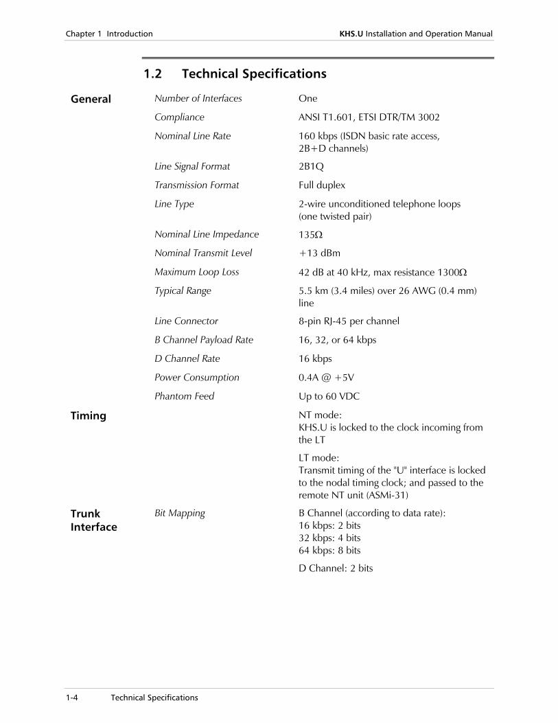
1.2 Technical Specifications
General Number of Interfaces One
Compliance ANSI T1.601, ETSI DTR/TM 3002
Nominal Line Rate 160 kbps (ISDN basic rate access, 2B+D channels)
Line Signal Format 2B1Q
Transmission Format Full duplex
Line Type 2-wire unconditioned telephone loops (one twisted pair)
Nominal Line Impedance 135Ω
Nominal Transmit Level +13 dBm
Maximum Loop Loss 42 dB at 40 kHz, max resistance 1300Ω
Typical Range 5.5 km (3.4 miles) over 26 AWG (0.4 mm) line
Line Connector 8-pin RJ-45 per channel
B Channel Payload Rate 16, 32, or 64 kbps
D Channel Rate 16 kbps
Power Consumption 0.4A @ +5V
Phantom Feed Up to 60 VDC
Timing NT mode: KHS.U is locked to the clock incoming from the LT
LT mode: Transmit timing of the "U" interface is locked to the nodal timing clock; and passed to the remote NT unit (ASMi-31)
Trunk Interface
Bit Mapping B Channel (according to data rate): 16 kbps: 2 bits 32 kbps: 4 bits 64 kbps: 8 bits
D Channel: 2 bits
KHS.U Installation and Operation Manual Chapter 1 Introduction
Technical Specifications 1-5
Diagnostics B Channel Local (analog) loopback
Remote loopback
Indicators LOSS (red) On when a loss of synchronization occurs
TST (yellow) On when a loopback test is active
Configuration Programmable via the Kilomux front panel, an ASCII terminal connected to the Kilomux supervisory port directly or via Telnet, or a RADview network management station over SNMP

Chapter 1 Introduction KHS.U Installation and Operation Manual
1-6 Technical Specifications
Module Installation 2-1
Chapter 2 Module Installation and Operation
2.1 Scope
This chapter provides installation and operation instructions for the KHS.U module. The information presented in this chapter supplements the general installation, configuration and operation instructions contained in the Kilomux System Installation and Operation Manual.
The KHS.U module contains components sensitive to electrostatic discharge (ESD). To prevent ESD damage, always hold the module by its sides, and do not touch the module components or connectors.
2.2 Module Installation
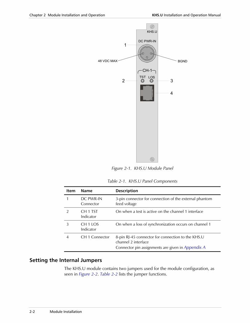
Module Panels All connectors and LED indicators are located on the KHS.U panel, as seen in Figure 2-1, and detailed in Table 2-1. The numbers under the heading "Item" correspond to the identification numbers in Figure 2-1.
Caution
Chapter 2 Module Installation and Operation KHS.U Installation and Operation Manual
2-2 Module Installation
KHS.U
DC PWR-IN
LOSTST3
4
2
1
CH-1
48 VDC MAX BGND
Figure 2-1. KHS.U Module Panel
Table 2-1. KHS.U Panel Components
Item Name Description
1 DC PWR-IN Connector
3-pin connector for connection of the external phantom feed voltage
2 CH 1 TST Indicator
On when a test is active on the channel 1 interface
3 CH 1 LOS Indicator
On when a loss of synchronization occurs on channel 1
4 CH 1 Connector 8-pin RJ-45 connector for connection to the KHS.U channel 2 interface Connector pin assignments are given in Appendix A
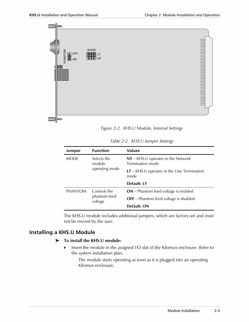
Setting the Internal Jumpers The KHS.U module contains two jumpers used for the module configuration, as seen in Figure 2-2. Table 2-2 lists the jumper functions.
KHS.U Installation and Operation Manual Chapter 2 Module Installation and Operation
Module Installation 2-3
MODELTNT
PH
ANTO
M
ON
OFF
Figure 2-2. KHS.U Module, Internal Settings
Table 2-2. KHS.U Jumper Settings
Jumper Function Values
MODE Selects the module operating mode
NT – KHS.U operates in the Network Termination mode
LT – KHS.U operates in the Line Termination mode
Default: LT
PHANTOM Controls the phantom feed voltage
ON – Phantom feed voltage is enabled
OFF – Phantom feed voltage is disabled
Default: ON
The KHS.U module includes additional jumpers, which are factory-set and must not be moved by the user.
Installing a KHS.U Module To install the KHS.U module:
• Insert the module in the assigned I/O slot of the Kilomux enclosure. Refer to the system installation plan.
The module starts operating as soon as it is plugged into an operating Kilomux enclosure.
Chapter 2 Module Installation and Operation KHS.U Installation and Operation Manual
2-4 Normal Indications
Connecting the Cables To connect the KHS.U module interface:
• Identify the cables intended for connection to each channel of this module, and plug them into the appropriate module connectors.
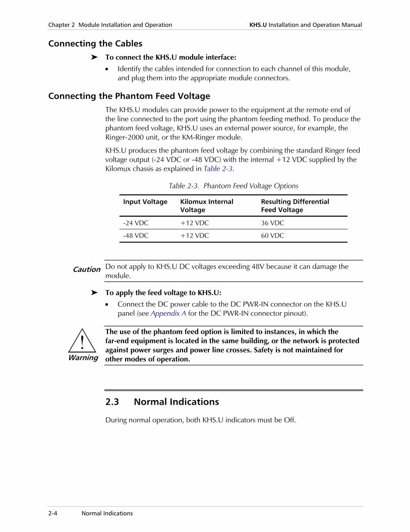
Connecting the Phantom Feed Voltage The KHS.U modules can provide power to the equipment at the remote end of the line connected to the port using the phantom feeding method. To produce the phantom feed voltage, KHS.U uses an external power source, for example, the Ringer-2000 unit, or the KM-Ringer module.
KHS.U produces the phantom feed voltage by combining the standard Ringer feed voltage output (-24 VDC or -48 VDC) with the internal +12 VDC supplied by the Kilomux chassis as explained in Table 2-3.
Table 2-3. Phantom Feed Voltage Options
Input Voltage Kilomux Internal Voltage
Resulting Differential Feed Voltage
-24 VDC +12 VDC 36 VDC
-48 VDC +12 VDC 60 VDC
Do not apply to KHS.U DC voltages exceeding 48V because it can damage the module.
To apply the feed voltage to KHS.U:
• Connect the DC power cable to the DC PWR-IN connector on the KHS.U panel (see Appendix A for the DC PWR-IN connector pinout).
The use of the phantom feed option is limited to instances, in which the far-end equipment is located in the same building, or the network is protected against power surges and power line crosses. Safety is not maintained for other modes of operation.
2.3 Normal Indications
During normal operation, both KHS.U indicators must be Off.
Caution
Warning
KHS.U Installation and Operation Manual Chapter 2 Module Installation and Operation
Configuring KHS.U via the Front Panel 2-5
2.4 Configuring KHS.U via the Front Panel
This section provides configuration instructions for the KHS.U module using the Kilomux front panel. The instructions appearing in this section assume you are familiar with the Kilomux front panel. If necessary, refer to Kilomux System Installation and Operation Manual for general front panel operating instructions, and for instructions on the execution of other configuration activities.
Before starting the configuration procedure, obtain the list of prescribed channel parameters from the system administrator.
Configuring Channel Parameters To configure a specific channel:
1. Display CH PARM on the Kilomux front panel LCD.
2. Scroll the channel identification field until you see the required module and channel numbers.
3. After the required channel is selected, assign values to the channel parameters.
The KHS.U B-channels are identified as follows:
• KHS.U/S: B channel 1 – channel 1 B channel 2 – channel 2.
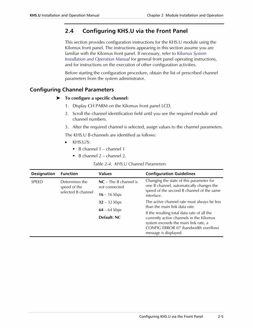
Table 2-4. KHS.U Channel Parameters
Designation Function Values Configuration Guidelines
SPEED Determines the speed of the selected B channel
NC – The B channel is not connected
16 – 16 kbps
32 – 32 kbps
64 – 64 kbps
Default: NC
Changing the state of this parameter for one B channel, automatically changes the speed of the second B channel of the same interface. The active channel rate must always be less than the main link data rate. If the resulting total data rate of all the currently active channels in the Kilomux system exceeds the main link rate, a CONFIG ERROR 07 (bandwidth overflow) message is displayed.
Chapter 2 Module Installation and Operation KHS.U Installation and Operation Manual
2-6 Configuring KHS.U via the Front Panel
Table 2-4. KHS.U Channel Parameters (Cont.)
Designation Function Values Configuration Guidelines
D-CONNECT Controls the transfer of the D channel associated with the selected interface
YES – D channel is connected to the main link
NO – D channel is not connected to the main link
Default: NO
If after selecting YES, the resulting total data rate of all currently active channels exceeds the main link rate, a CONFIG ERROR 07 (bandwidth overflow) message is displayed
MODE Displays the operating mode of the KHS.U module
LT – KHS.U module operates in the LTU mode
NT – KHS.U module operates in the NTU mode
This is a read-only parameter, which reflects the position of the KHS.U MODE jumper
U_TYPE Determines the operation mode of the "U" interface
T0 – Normal operation
T1 – For application specific customization
T2 – For future use
T3 – For future use
The operation mode depends on the ISDN interface type
Outline of Configuration Procedure 3-1
Chapter 3 Configuration via Supervision Terminal
3.1 Introduction
This chapter provides specific instructions for the configuration of the KHS.U module using a supervision terminal. The configuration activities are performed by means of the management system used to control the Kilomux system.
The instructions appearing in this chapter assume you are familiar with the operation and capabilities of the supervision terminal. If necessary, refer to the Kilomux System Installation and Operation Manual for general operating instructions, and for instructions on the execution of other configuration activities.
3.2 Outline of Configuration Procedure
The configuration procedure for a new KHS.U includes the following main steps:
• Inclusion of a KHS.U module not yet installed in the Kilomux database. This allows the pre-programming of the module parameters, so that when the module is installed in the enclosure, it immediately starts operating in the required mode. This function is performed by means of the DEF SYS command.
• Programming of the module channel parameters, using the DEF CH command.
Chapter 3 Configuration via Supervision Terminal KHS.U Installation and Operation Manual
3-2 Configuring KHS.U
3.3 Configuring KHS.U
If the supervision terminal is not yet connected to the Kilomux enclosure, connect the terminal and start a configuration session in accordance with the Kilomux System Installation and Operation Manual.
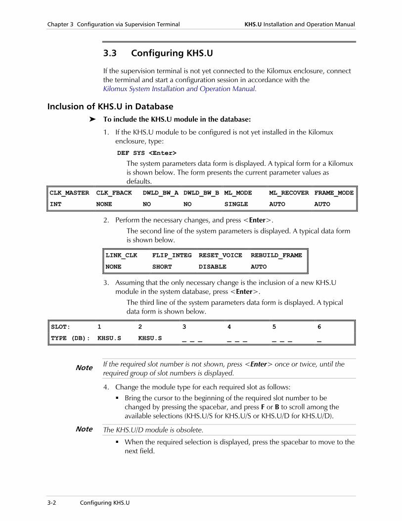
Inclusion of KHS.U in Database To include the KHS.U module in the database:
1. If the KHS.U module to be configured is not yet installed in the Kilomux enclosure, type:
DEF SYS <Enter>
The system parameters data form is displayed. A typical form for a Kilomux is shown below. The form presents the current parameter values as defaults.
CLK_MASTER CLK_FBACK DWLD_BW_A DWLD_BW_B ML_MODE ML_RECOVER FRAME_MODE
INT NONE NO NO SINGLE AUTO AUTO
2. Perform the necessary changes, and press <Enter>. The second line of the system parameters is displayed. A typical data form is shown below.
LINK_CLK FLIP_INTEG RESET_VOICE REBUILD_FRAME
NONE SHORT DISABLE AUTO
3. Assuming that the only necessary change is the inclusion of a new KHS.U module in the system database, press <Enter>.
The third line of the system parameters data form is displayed. A typical data form is shown below.
SLOT: 1 2 3 4 5 6
TYPE (DB): KHSU.S KHSU.S _ _ _ _ _ _ _ _ _ _
If the required slot number is not shown, press <Enter> once or twice, until the required group of slot numbers is displayed.
4. Change the module type for each required slot as follows: Bring the cursor to the beginning of the required slot number to be
changed by pressing the spacebar, and press F or B to scroll among the available selections (KHS.U/S for KHS.U/S or KHS.U/D for KHS.U/D).
The KHS.U/D module is obsolete.
When the required selection is displayed, press the spacebar to move to the next field.
Note
Note
KHS.U Installation and Operation Manual Chapter 3 Configuration via Supervision Terminal
Configuring KHS.U 3-3
5. After the required selections are made, press <Enter> to end. The supervision terminal displays the time and date fields, followed by the Kilomux system prompt.
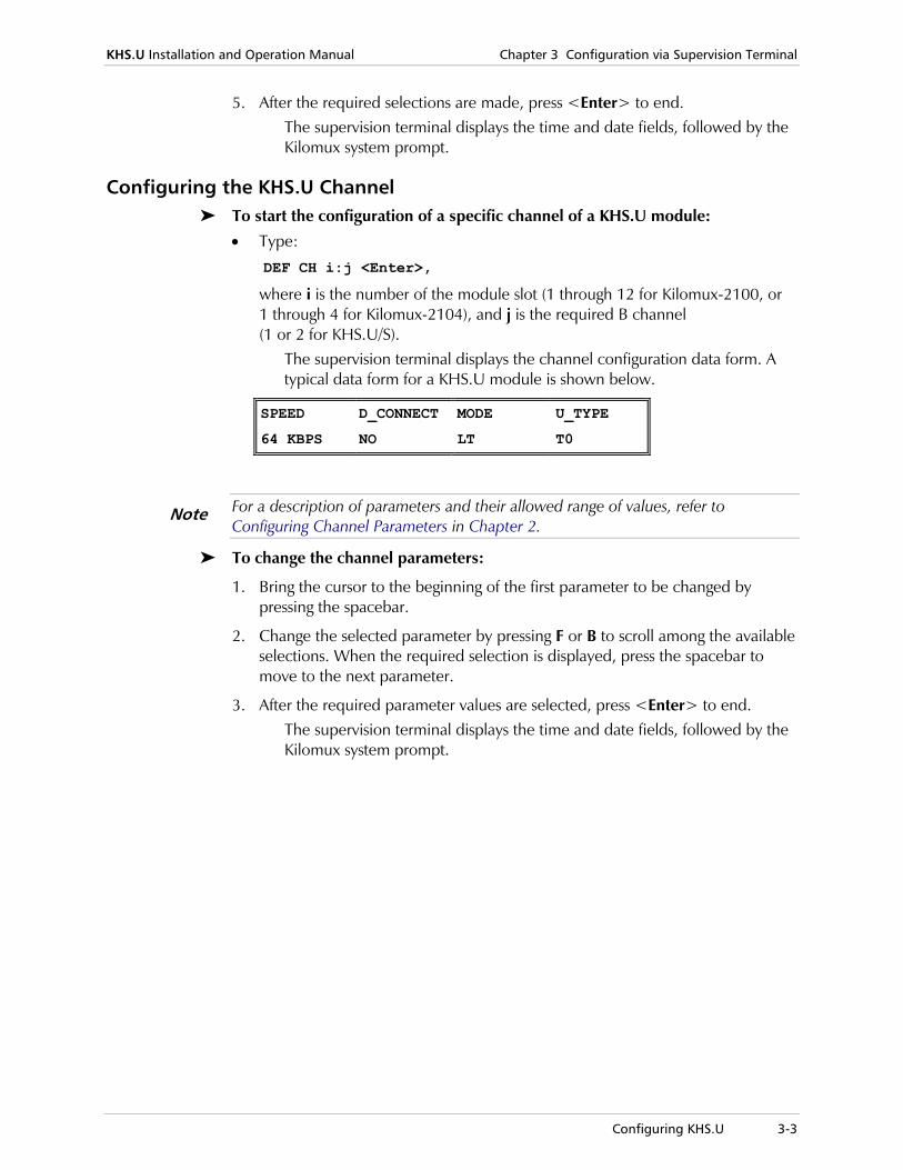
Configuring the KHS.U Channel To start the configuration of a specific channel of a KHS.U module:
• Type:
DEF CH i:j <Enter>,
where i is the number of the module slot (1 through 12 for Kilomux-2100, or 1 through 4 for Kilomux-2104), and j is the required B channel (1 or 2 for KHS.U/S).
The supervision terminal displays the channel configuration data form. A typical data form for a KHS.U module is shown below.
SPEED D_CONNECT MODE U_TYPE
64 KBPS NO LT T0
For a description of parameters and their allowed range of values, refer to Configuring Channel Parameters in Chapter 2.
To change the channel parameters:
1. Bring the cursor to the beginning of the first parameter to be changed by pressing the spacebar.
2. Change the selected parameter by pressing F or B to scroll among the available selections. When the required selection is displayed, press the spacebar to move to the next parameter.
3. After the required parameter values are selected, press <Enter> to end. The supervision terminal displays the time and date fields, followed by the Kilomux system prompt.
Note

Chapter 3 Configuration via Supervision Terminal KHS.U Installation and Operation Manual
3-4 Configuring KHS.U
Diagnostic Functions 4-1
Chapter 4 Alarms and Diagnostics
4.1 Introduction
This chapter provides information on module-specific tests, and diagnostic functions of KHS.U.
The diagnostic information presented in this chapter supplements the general Kilomux system diagnostics operation instructions (see the Kilomux System Installation and Operation Manual).
4.2 Diagnostic Functions
The available diagnostic functions of KHS.U include:
• Local channel loopback
• Remote channel loopback.
The following sections describe the available test activities.
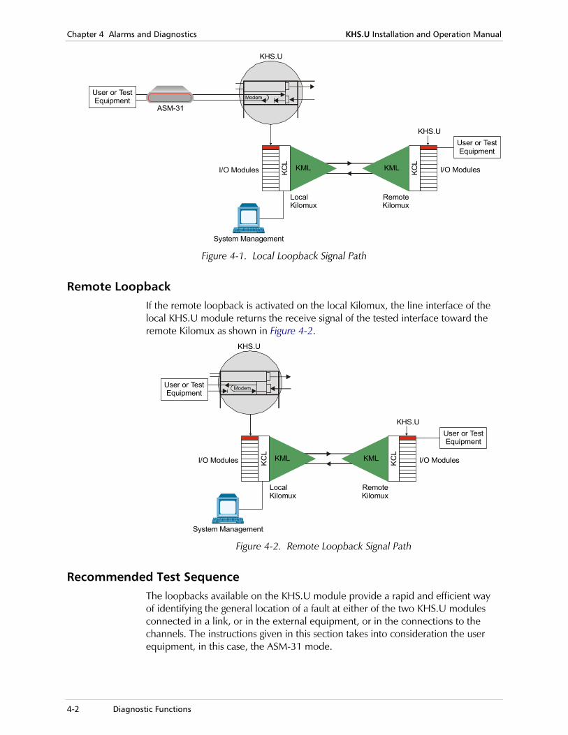
Local Loopback When the local loopback is active, the digital output signal of the modem that processes the analog line signal is connected to the input of the modem receive path, and is returned toward the user equipment, e.g., toward the locally-connected ASM-31, as shown in Figure 4-1. The transmit signal is still sent to the remote Kilomux system.
Chapter 4 Alarms and Diagnostics KHS.U Installation and Operation Manual
4-2 Diagnostic Functions
KHS.U
ASM-31
I/O Modules
User or TestEquipment
KHS.U
KC
L
KC
L
I/O Modules
User or TestEquipment
System Management
LocalKilomux
RemoteKilomux
KML KML
Modem
Figure 4-1. Local Loopback Signal Path
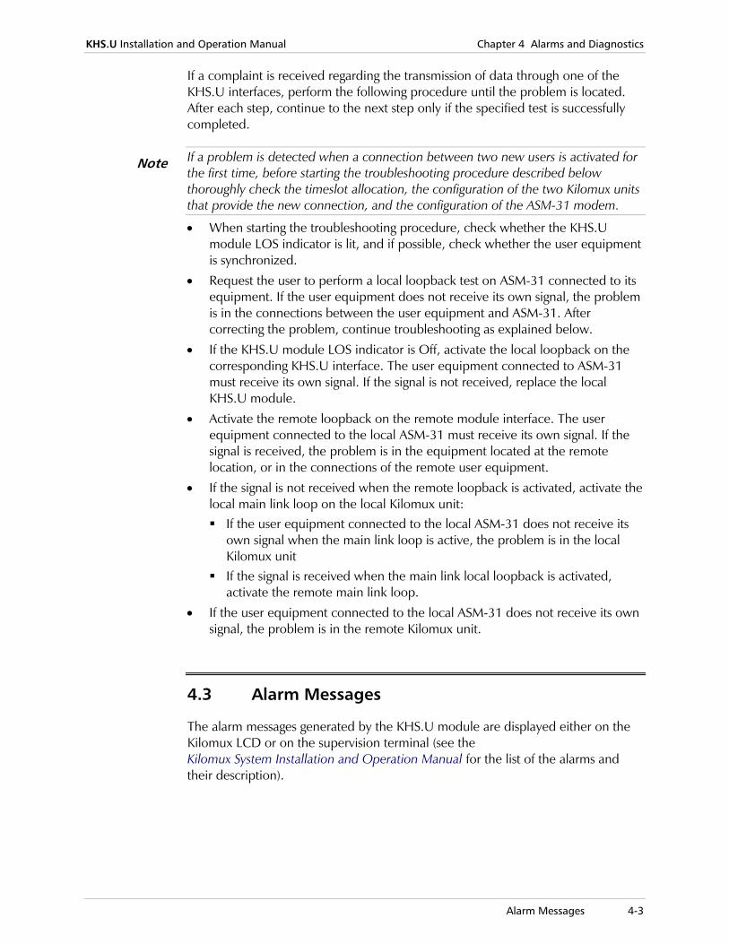
Remote Loopback If the remote loopback is activated on the local Kilomux, the line interface of the local KHS.U module returns the receive signal of the tested interface toward the remote Kilomux as shown in Figure 4-2.
KHS.U
I/O Modules
User or TestEquipment
KHS.U
KC
L
KC
L
I/O Modules
User or TestEquipment
System Management
LocalKilomux
RemoteKilomux
KML KML
Modem
Figure 4-2. Remote Loopback Signal Path
Recommended Test Sequence The loopbacks available on the KHS.U module provide a rapid and efficient way of identifying the general location of a fault at either of the two KHS.U modules connected in a link, or in the external equipment, or in the connections to the channels. The instructions given in this section takes into consideration the user equipment, in this case, the ASM-31 mode.
KHS.U Installation and Operation Manual Chapter 4 Alarms and Diagnostics
Alarm Messages 4-3
If a complaint is received regarding the transmission of data through one of the KHS.U interfaces, perform the following procedure until the problem is located. After each step, continue to the next step only if the specified test is successfully completed.
If a problem is detected when a connection between two new users is activated for the first time, before starting the troubleshooting procedure described below thoroughly check the timeslot allocation, the configuration of the two Kilomux units that provide the new connection, and the configuration of the ASM-31 modem.
• When starting the troubleshooting procedure, check whether the KHS.U module LOS indicator is lit, and if possible, check whether the user equipment is synchronized.
• Request the user to perform a local loopback test on ASM-31 connected to its equipment. If the user equipment does not receive its own signal, the problem is in the connections between the user equipment and ASM-31. After correcting the problem, continue troubleshooting as explained below.
• If the KHS.U module LOS indicator is Off, activate the local loopback on the corresponding KHS.U interface. The user equipment connected to ASM-31 must receive its own signal. If the signal is not received, replace the local KHS.U module.
• Activate the remote loopback on the remote module interface. The user equipment connected to the local ASM-31 must receive its own signal. If the signal is received, the problem is in the equipment located at the remote location, or in the connections of the remote user equipment.
• If the signal is not received when the remote loopback is activated, activate the local main link loop on the local Kilomux unit: If the user equipment connected to the local ASM-31 does not receive its
own signal when the main link loop is active, the problem is in the local Kilomux unit If the signal is received when the main link local loopback is activated,
activate the remote main link loop.
• If the user equipment connected to the local ASM-31 does not receive its own signal, the problem is in the remote Kilomux unit.
4.3 Alarm Messages
The alarm messages generated by the KHS.U module are displayed either on the Kilomux LCD or on the supervision terminal (see the Kilomux System Installation and Operation Manual for the list of the alarms and their description).
Note
Chapter 4 Alarms and Diagnostics KHS.U Installation and Operation Manual
4-4 Technical Support
4.4 Technical Support
Technical support for this product can be obtained from the local distributor from whom it was purchased.
For further information, please contact the RAD distributor nearest you or one of RAD's offices worldwide. This information can be found at www.rad.com (offices – About RAD > Worldwide Offices; distributors – Where to Buy > End Users).
DC PWR-IN Connector A-1
Appendix A Connection Data
A.1 Interface Connectors
Each interface of the KHS.U module terminates in an RJ-45 connector wired in accordance with Table A-1.
Table A-1. RJ-45 Connector Pin Assignment
Pin Function
1, 2, 3 Not connected
4 Line wire
5 Line wire
6, 7, 8 Not connected
A.2 DC PWR-IN Connector
Table A-2 lists the pinout of the KHS.U DC PWR-IN connector.
Table A-2. DC PWR-IN Connector Pin Assignment
Pin Function
1 Common Ground
2 Not connected
3 Feed Voltage (-48 VDC or -24 VDC)
Appendix A Connection Data KHS.U Installation and Operation Manual
A-2 DC PWR-IN Connector
24 Raoul Wallenberg St., Tel Aviv 69719, IsraelTel: +972-3-6458181, Fax: +972-3-6483331, +972-3-6498250E-mail: , Web site:
Customer Response Form RAD Data Communications would like your help in improving its product documentation. Please complete and return this form by mail or by fax or send us an e-mail with your comments. Thank you for your assistance!
Manual Name: ______________________________________________________________
Publication Number: __________________________________________________________ Please grade the manual according to the following factors:
Excellent Good Fair Poor Very Poor
Installation instructions Operating instructions Manual organization Illustrations The manual as a whole
What did you like about the manual? ___________________________________________________________________________ ___________________________________________________________________________ ___________________________________________________________________________ ___________________________________________________________________________ ___________________________________________________________________________
[email protected] www.rad.com
KHS.U
420-212-05/06


Error Report Type of Error(s) Incompatibility with product
or Problem(s): Difficulty in understanding text
Regulatory information (Safety, Compliance, Warnings, etc.)
Difficulty in finding needed information
Missing information
Illogical flow of information
Style (spelling, grammar, references, etc.)
Appearance
Other _________
Please list the exact page numbers with the error(s), detail the errors you found (information missing, unclear or inadequately explained, etc.) and attach the page to your fax, if necessary. _________________________________________________________________________________________
_________________________________________________________________________________________
_________________________________________________________________________________________
_________________________________________________________________________________________
Please add any comments or suggestions you may have. _________________________________________________________________________________________
_________________________________________________________________________________________
_________________________________________________________________________________________
You are: Distributor
End user
VAR
Other ________________________
Who is your distributor? _______________________________
Your name and company: ___________________________________________________________
Job title: __________________________________________________________________________
Address: __________________________________________________________________________
Direct telephone number and extension: _______________________________________________
Fax number: ______________________________________________________________________
E-mail: _____________________________________________________________________


Publication No. 420-212-05/06
www.rad.com
INTERNATIONAL HEADQUARTERS: 24 Raoul Wallenberg Street, Tel Aviv 69719, Israel, Tel: 972-3-6458181
Fax: 972-3-6498250, 972-3-6474436, Email: [email protected]
NORTH AMERICA HEADQUARTERS: 900 Corporate Drive, Mahwah, N.J. 07430, Tel: (201) 529-1100
Toll Free: 1-800-444-7234, Fax: (201) 529-5777, Email: [email protected]


![Rev. 0901 KJR Ring Sensors - Pulsotronic Anlagentechnik GmbH...Static - PNP (normally open) Analog [0 .. 10V] Operating voltage 20 - 30 VDC 10 - 30 VDC 18 - 30 VDC f-state current](https://img.pdfslide.us/doc/110x75/608fe4a8684d86037b780ed7/rev-0901-kjr-ring-sensors-pulsotronic-anlagentechnik-gmbh-static-pnp-normally.jpg)