Embed Size (px)
Citation preview

© 2018Litho U.S.A.
Page 1
KHA/KHBService Literature 7.5 / 8.5 / 10 / 12.5 TON
26.3 / 29.8 / 35.2 / 44 kWCorp. 1012-L5
Revised 05/2020
KHA/KHB SERIESThe KHA/KHB commercial heat pump is available in 7.5, 8.5,
10 and 12.5 ton capacities. The KHB commercial heat pump
is available in 7.5, 8.5 and 10 ton capacities. The
KHA092/150 and KHB 092/122 refrigerant systems utilize
two compressors, two reversing valves, two accumula
tors, and other parts common to a heat pump. Optional
auxiliary electric heat is factory or field installed in KHA/
KHB units. Electric heat operates in single or multiple
stages depending on the kW input size. 7.5kW through
60kW heat sections are available for the KHA/KHB heat
pump.
KHA/KHB units are designed to accept any of several differ
ent energy management thermostat control systems with
minimum field wiring.
Information contained in this manual is intended for use by
qualified service technicians only. All specifications are sub
ject to change. Procedures outlined in this manual are pre
sented as a recommendation only and do not supersede or
replace local or state codes.
If the unit must be lifted for service, rig unit by attaching four
cables to the holes located in the unit base rail (two holes at
each corner). Refer to the installation instructions for the prop
er rigging technique.
ELECTROSTATIC DISCHARGE (ESD)
Precautions and Procedures
CAUTIONElectrostatic discharge can affect electronic components. Take precautionsto neutralize electrostatic charge bytouching your hand and tools to metalprior to handling the control.
WARNINGImproper installation, adjustment, alteration, serviceor maintenance can cause property damage, personal injury or loss of life. Installation and service mustbe performed by a qualified installer or serviceagency.
CAUTIONAs with any mechanical equipment, contact withsharp sheet metal edges can result in personal injury. Take care while handling this equipment andwear gloves and protective clothing.
WARNINGElectric shock hazard. Can cause injuryor death. Before attempting to performany service or maintenance, turn theelectrical power to unit OFF at disconnect switch(es). Unit may have multiplepower supplies.
Table of Contents
Options / Accessories 2. . . . . . . . . . . . . . . . . . . . . . . . . .
Optional Electric Heat Accessories 3. . . . . . . . . . . . . .
Specifications 6. . . . . . . . . . . . . . . . . . . . . . . . . . . . . . . . .
Blower Data 8. . . . . . . . . . . . . . . . . . . . . . . . . . . . . . . . . .
Electrical Data 13. . . . . . . . . . . . . . . . . . . . . . . . . . . . . . . .
Parts Arrangement 21. . . . . . . . . . . . . . . . . . . . . . . . . . . .
I Unit Components 22. . . . . . . . . . . . . . . . . . . . . . . . . . . .
Control Box 22. . . . . . . . . . . . . . . . . . . . . . . . . . . . . . .
Cooling 31. . . . . . . . . . . . . . . . . . . . . . . . . . . . . . . . . . .
Blower Compartment 30. . . . . . . . . . . . . . . . . . . . . . .
Electric Heat 38. . . . . . . . . . . . . . . . . . . . . . . . . . . . . . .
II Placement and Installation 41. . . . . . . . . . . . . . . . . . . .
III Start Up 41. . . . . . . . . . . . . . . . . . . . . . . . . . . . . . . . . . .
IV System Service Checks 42. . . . . . . . . . . . . . . . . . . . .
V Maintenance 43. . . . . . . . . . . . . . . . . . . . . . . . . . . . . . . .
VI Accessories 45. . . . . . . . . . . . . . . . . . . . . . . . . . . . . . . .
VII Wiring Diagrams 52. . . . . . . . . . . . . . . . . . . . . . . . . . .

Page 2
OPTIONS / ACCESSORIES
Item Description Model Number
Catalog Number
Unit Model NoKHA KHB 092
KHA KHB 102
KHA
120
KHB 122
KHA
150COOLING SYSTEMCondensate Drain Trap PVC - C1TRAP20AD2 76W26 X X X X X
Copper - C1TRAP10AD2 76W27 X X X X XCorrosion Protection Factory O O O O ODrain Pan Overflow Switch K1SNSR71AB1- 74W42 X X X X XEfficiency Standard O O O O
High O O OLow Ambient Kit Standard Efficiency - K1SNSR33B-1 54W16 X X X X
High Efficiency - K1SNSR34*B0 14N31 X X XRefrigerant Type R-410A O O O O OBLOWER - SUPPLY AIRBlower Option CAV (Constant Air Volume) Factory O O O
MSAV® (Multi-Stage Air Volume) Factory O O O ODirectPlus™ (Direct Drive) MSAV® (Multi-Stage Air Volume) Factory O
Blower Motors Belt Drive - 2 hp Factory O O O OBelt Drive - 3 hp Factory O O O OBelt Drive - 5 hp Factory O O O O
VFD Manual Bypass Kit (for MSAV equipped units only) KVFDB12C-1 90W53 X X X XDrive KitsSee Blower Data Tables for selection
Kit #1 590-890 rpm Factory O O O OKit #2 800-1105 rpm Factory O O O OKit #3 795-1195 rpm Factory O O O O
Kit #4 730-970 rpm Factory O O O OKit #5 940-1200 rpm Factory O O O O
Kit #6 1015-1300 rpm Factory O O O OKit #10 900-1135 rpm Factory O O O O
Kit #11 1040-1315 rpm Factory O O O OKit #12 1125-1425 rpm Factory O O O O
CABINETCombination Coil/Hail Guards Standard Efficiency - K1GARD51BS1 13T24 X X X
Standard Efficiency - K1GARD51BP1 13T25 XHigh Efficiency - K1GARD53B-1 14Y77 X X
High Efficiency - E1GARD51BP1 13T06 XHinged Access Panels Factory O O O O OHorizontal Discharge Kit K1HECK00B-1 51W25 X X X X XReturn Air Adaptor Plate (for LC/LG/LH and TC/TG/TH unit replacement) C1CONV10B-1 54W96 X X X X XCONTROLSCommercial Controls L Connection® Building Automation System - - - X X X X XBACnet® K0CTRL31B-1 96W15 OX OX OX OX OXBACnet® Thermostat with Display K0SNSR01FF1 97W23 X X X X XBACnet® Thermostat without Display K0SNSR00FF1 97W24 X X X X XNovar® 2051 K0CTRL30B-1 96W12 OX OX OX OX OXPlenum Cable (75 ft.) K0MISC00FF1 97W25 X X X X XSmoke Detector - Supply or Return (Power board and one sensor) C1SNSR44B-2 11K76 X X X X XSmoke Detector - Supply and Return (Power board and two sensors) C1SNSR43B-2 11K80 X X X X X
NOTE - Catalog and model numbers shown are for ordering field installed accessories.OX - Configure To Order (Factory Installed) or Field InstalledO = Configure To Order (Factory Installed)X = Field Installed

Page 3
OPTIONS / ACCESSORIES
Item Description Model Number
Catalog Number
Unit Model NoKHA KHB 092
KHA KHB 102
KHA
120
KHB 122
KHA
150INDOOR AIR QUALITYHealthy Climate® High Efficiency Air Filters 20 x 25 x 2 (Order 4 per unit)
MERV 8 - C1FLTR15B-1 50W61 X X X X XMERV 13 - C1FLTR40B-1 52W41 X X X X X
Replacement Media Filter With Metal Mesh Frame (includes non-pleated filter media)
C1FLTR30B-1- Y3063 X X X X X
Indoor Air Quality (CO2) SensorsSensor - Wall-mount, off-white plastic cover with LCD display C0SNSR50AE1L 77N39 X X X X XSensor - Wall-mount, off-white plastic cover, no display C0SNSR52AE1L 87N53 X X X X XSensor - Black plastic case with LCD display, rated for plenum mounting C0SNSR51AE1L 87N52 X X X X X
Sensor - Wall-mount, black plastic case, no display, rated for plenum mounting C0MISC19AE1 87N54 X X X X X
CO2 Sensor Duct Mounting Kit - for downflow applications C0MISC19AE1- 85L43 X X X X XAspiration Box - for duct mounting non-plenum rated CO2 sensors (87N53 or 77N39) C0MISC16AE1- 90N43 X X X X X
UVC Germicidal Lamps1 Healthy Climate® UVC Light Kit (208/230v-1ph) C1UVCL10B-1 54W62 X X X X XELECTRICALVoltage 60 hz 208/230V - 3 phase Factory O O O O O
460V - 3 phase Factory O O O O O575V - 3 phase Factory O O O O O
Disconnect Switch - See Electrical/Electric Heat tables for selection
80 amp - C1DISC080B-1 54W56 OX OX OX OX OX150 amp - C1DISC150B-1 54W57 OX OX OX OX OX
GFI Service Outlets
15 amp non-powered, field-wired (208/230V, 460V only) LTAGFIK10/15 74M70 OX OX OX OX OX20 amp non-powered, field-wired (575V only) C1GFCI20FF1 67E01 X X X X X
Weatherproof Cover for GFI C1GFCI99FF1 10C89 X X X X XELECTRIC HEAT- BELT DRIVE UNITS7.5 kW 208/230V-3ph - C1EH0075B-1Y 56W38 OX OX
460V-3ph - C1EH0075B-1G 56W39 OX OX575V-3ph - C1EH0075B-1J 56W40 OX OX
15 kW 208/230V-3ph - C1EH0015B-1Y 56W41 OX OX OX OX460V-3ph - C1EH0150B-1G 56W42 OX OX OX OX575V-3ph - C1EH0150B-1J 56W43 OX OX OX OX
22.5 kW 208/230V-3ph - C1EH0225B-1Y 56W44 OX OX OX OX460V-3ph - C1EH0225B-1G 56W45 OX OX OX OX575V-3ph - C1EH0225B-1J 56W46 OX OX OX OX
30 kW 208/230V-3ph - C1EH0300B-1Y 56W47 OX OX OX OX460V-3ph - C1EH0300B-1G 56W48 OX OX OX OX575V-3ph - C1EH0300B-1J 56W49 OX OX OX OX
45 kW 208/230V-3ph - C1EH0450B-1Y 56W50 OX OX OX OX460V-3ph - C1EH0450B-1G 56W51 OX OX OX OX575V-3ph - C1EH0450B-1J 56W52 OX OX OX OX
60 kW 208/230V-3ph - C1EH0600B-1Y 55W02 OX OX460V-3ph - C1EH0600B-1G 55W03 OX OX575V-3ph - C1EH0600B-1J 55W04 OX OX
NOTE - Catalog and model numbers shown are for ordering field installed accessories.OX - Configure To Order (Factory Installed) or Field InstalledO = Configure To Order (Factory Installed)X = Field Installed

Page 4
OPTIONS / ACCESSORIES
Item Description Model Number
Catalog Number
Unit Model NoKHA KHB 092
KHA KHB 102
KHA
120
KHB 122
KHA
150ELECTRIC HEAT- DIRECT DRIVE UNITS15 kW 208/230V-3ph - E1EH0150BP1Y 10U99 X
460V-3ph - E1EH0150BP1G 10X01 X575V-3ph - E1EH0150BP1J 10X02 X
22.5 kW 208/230V-3ph - E1EH0225BP1Y 10X03 X460V-3ph - E1EH0225BP1G 10X04 X575V-3ph - E1EH0225BP1J 10X05 X
30 kW 208/230V-3ph - E1EH0300BP1Y 10X06 X460V-3ph - E1EH0300BP1G 10X07 X575V-3ph - E1EH0300BP1J 10X08 X
45 kW 208/230V-3ph - E1EH0450BP1Y 10X09 X460V-3ph - E1EH0450BP1G 10X11 X575V-3ph - E1EH0450BP1J 10X12 X
60 kW 208/230V-3ph - E1EH0600BP1Y 10X13 X460V-3ph - E1EH0600BP1G 10X14 X575V-3ph - E1EH0600BP1J 10X15 X
ECONOMIZERStandard Economizer (Not for Title 24)Standard Economizer with Single Temperature Control Downflow or Horizontal Applications - Includes Barometric Relief Dampers and Air Hoods
K1ECON20B-2 13U45 OX OX OX OX OX
Standard Economizer Controls (Not for Title 24)Single Enthalpy Control C1SNSR64FF1 53W64 OX OX OX OX OXDifferential Enthalpy Control (order 2) C1SNSR64FF1 53W64 X X X X XHigh Performance Economizer (Approved for California Title 24 Building Standards / AMCA Class 1A Certified)High Performance Economizer with Single Temperature Control Downflow or Horizontal Applications - Includes Barometric Relief Dampers and Air Hoods
K1ECON22B-1 10U58 OX OX OX OX OX
High Performance Economizer Controls (Not for Title 24)Single Enthalpy Control C1SNSR60FF1 10Z75 OX OX OX OX OXDifferential Enthalpy Control (order 2) C1SNSR60FF1 10Z75 X X X X XHorizontal Low Profile Barometric Relief Dampers With Exhaust HoodHorizontal Low Profile Barometric Relief Dampers With Exhaust Hood LAGEDH03/15 53K04 X X X X XOUTDOOR AIROutdoor Air Dampers with Outdoor Air HoodMotorized C1DAMP20B-1 14G28 OX OX OX OX OXManual C1DAMP10B-2 14G29 OX OX OX OX OXPOWER EXHAUSTStandard Static 208/230V-3ph - K1PWRE10B-1Y 53W44 X X X X X
460V-3ph - K1PWRE10B-1G 53W45 X X X X X575V-3ph - K1PWRE10B-1J 53W46 X X X X X
NOTE - Catalog and model numbers shown are for ordering field installed accessories.OX - Configure To Order (Factory Installed) or Field InstalledO = Configure To Order (Factory Installed)X = Field Installed

Page 5
OPTIONS / ACCESSORIES
Item Description Model Number
Catalog Number
Unit Model NoKHA KHB 092
KHA KHB 102
KHA
120
KHB 122
KHA
150ROOF CURBSHybrid Roof Curbs, Downflow8 in. height C1CURB70B-1 11F54 X X X X X14 in. height C1CURB71B-1 11F55 X X X X X18 in. height C1CURB72B-1 11F56 X X X X X24 in. height C1CURB73B-1 11F57 X X X X XAdjustable Pitch Curb, Downflow14 in. height C1CURB55B-1 54W50 X X X X X
CEILING DIFFUSERS
Step-Down - Order one RTD11-95S 13K61 XRTD11-135S 13K62 X X XRTD11-185S 13K63 X
Flush - Order one FD11-95S 13K56 XFD11-135S 13K57 X X XFD11-185S 13K58 X
Transitions (Supply and Return) - Order one C1DIFF30B-1 12X65 XC1DIFF31B-1 12X66 X X XC1DIFF32B-1 12X67 X
NOTE - Catalog and model numbers shown are for ordering field installed accessories.OX - Configure To Order (Factory Installed) or Field InstalledO = Configure To Order (Factory Installed)X = Field Installed

Page 6
SPECIFICATIONS - STANDARD EFFICIENCYGeneral Data Nominal Tonnage 7.5 Ton 8.5 Ton 10 Ton 12.5 Ton
Model Number KHA092S4M KHA102S4M KHA120S4M KHA150S4MEfficiency Type Standard Standard Standard Standard
Blower Type MSAV (Multi-Stage Air Volume)
MSAV (Multi-Stage Air Volume)
MSAV (Multi-Stage Air Volume)
MSAV (Multi-Stage Air Volume)
Cooling Performance
Gross Cooling Capacity - Btuh 91,600 103,400 121,500 144,3001 Net Cooling Capacity - Btuh 89,000 100,000 118,000 138,000
AHRI Rated Air Flow - cfm 3000 3400 3600 4500Total Unit Power - kW 8.1 9.1 10.7 13.0
1 EER (Btuh/Watt) 11 11 11.0 10.61 IEER (Btuh/Watt) 12.5 12.5 12.5 12.0
Refrigerant Type R-410A R-410A R-410A R-410ARefrigerant Charge
FurnishedCircuit 1 12 lbs. 8 oz. 13 lbs. 8 oz. 15 lbs. 0 oz. 22 lbs. 0 oz.Circuit 2 12 lbs. 0 oz. 13 lbs. 0 oz. 15 lbs. 0 oz. 23 lbs. 0 oz.
Heating Performance
1 Total High Heat Capacity - Btuh 89,000 100,000 115,000 138,000Total Unit Power - kW 7.9 8.9 10.3 12.6
1 C.O.P. 3.3 3.3 3.30 3.201 Total Low Heat Capacity - Btuh 53,000 55,000 70,000 82,000
Total Unit Power (kW) 6.9 7.2 9.4 11.71 C.O.P. 2.25 2.25 2.25 2.05
Electric Heat Available - See page 14 7.5, 15, 22.5, 30 & 45 kW 15, 22.5, 30, 45 & 60 kWCompressor Type (number) Scroll (2) Scroll (2) Scroll (2) Scroll (2)Outdoor Coils
Net face area (total) - sq. ft. 28.8 28.8 28.8 40.8Tube diameter - in. 3/8 3/8 3/8 3/8
Number of rows 2 2 3 3Fins per inch 20 20 20 20
Outdoor Coil Fans
Motor - (No.) horsepower (2) 1/3 PSC (2) 1/2 PSC (2) 1/2 PSC (3) 1/3 PSCMotor rpm 1075 1075 1075 1075
Total Motor watts 665 775 806 1150Diameter - (No.) in. (2) 24 (2) 24 (2) 24 (3) 24
Number of blades 3 3 3 3Total Air volume - cfm 8200 8600 8800 11,000
Indoor Coils
Net face area (total) - sq. ft. 12.8 12.8 12.8 12.8Tube diameter - in. 3/8 3/8 3/8 3/8
Number of rows 3 4 4 4Fins per inch 14 14 14 14
Drain connection - Number and size (1) 1 in. NPT couplingExpansion device type Balance port TXV, removable head
2 Indoor Blower and Drive Selection
Nominal motor output 2 hp, 3 hp, 5 hpMaximum usable motor output
(US Only)2.3 hp, 3.45 hp, 5.75 hp
Motor - Drive kit number 2 hp 3 Kit 1 590-890 rpm Kit 2 800-1105 rpm Kit 3 795-1195 rpm
3 hp Kit 4 730-970 rpm Kit 5 940-1200 rpm Kit 6 1015-1300 rpm
5 hp Kit 10 900-1135 rpm Kit 11 1040-1315 rpm Kit 12 1125-1425 rpm
Blower wheel nominal diameter x width - in. (1) 15 X 15 (1) 15 X 15 (1) 15 X 15 (1) 15 X 15Filters Type of filter Disposable
Number and size - in. (4) 20 x 25 x 2Electrical characteristics 208/230V, 460V or 575V - 60 hertz - 3 phaseNOTE - Net capacity includes evaporator blower motor heat deduction. Gross capacity does not include evaporator blower motor heat deduction.1 AHRI Certified to AHRI Standard 340/360: Cooling Ratings - 95°F outdoor air temperature and 80°F db/67°F wb entering indoor coil air. High Temperature Heating Ratings - 47°F db/43°F wb outdoor air temperature and 70°F entering indoor coil air. Low Temperature Heating Ratings - 17°F db/15°F wb outdoor air temperature and 70°F entering indoor coil air.
2 Using total air volume and system static pressure requirements determine from blower performance tables rpm and motor output required. Maximum usable output of motors furnished are shown. In Canada, nominal motor output is also maximum usable motor output. If motors of comparable output are used, be sure to keep within the service factor limitations outlined on the motor nameplate.
4 Standard motor and drive kit furnished with unit.NOTE – Units equipped with MSAV® (Multi-Stage Air Volume)option are limited to a motor service factor of 1.0.

Page 7
SPECIFICATIONS - HIGH EFFICIENCYGeneral Data Nominal Tonnage 7.5 Ton 7.5 Ton 8.5 Ton 8.5 Ton 10 Ton
Model Number KHB092H4B KHB092H4M KHB102H4B KHB102H4M KHB122H4EEfficiency Type High High High High High
Blower Type Constant Air Volume (CAV)
MSAV (Multi-Stage Air Volume)
Constant Air Volume (CAV)
MSAV (Multi-Stage Air Volume)
MSAV (Multi-Stage Air Volume)
DirectPlus™ (Direct Drive)
Cooling Performance
Gross Cooling Capacity - Btuh 91,600 91,600 103,400 103,400 121,0001 Net Cooling Capacity - Btuh 89,000 89,000 100,000 100,000 118,000
AHRI Rated Air Flow - cfm 3,000 3,000 3,400 3,400 3600Total Unit Power - kW 7.3 7.3 8.3 8.3 9.6
1 EER (Btuh/Watt) 12.1 12.1 12.0 12.0 12.31 IEER (Btuh/Watt) 12.9 14.2 12.5 14.3 14.8
Refrigerant Type R-410A R-410A R-410A R-410A R-410ARefrigerant Charge
FurnishedCircuit 1 13 lbs. 8 oz. 13 lbs. 8 oz. 13 lbs. 8 oz. 13 lbs. 8 oz. 19 lbs. 8 oz.Circuit 2 13 lbs. 8 oz. 13 lbs. 8 oz. 13 lbs. 0 oz. 13 lbs. 0 oz. 20 lbs. 8 oz.
Heating Performance
1 Total High Heat Capacity - Btuh 86,000 86,000 100,000 100,000 116,000Total Unit Power - kW 7.0 7.0 8.1 8.1 9.5
1 C.O.P. 3.60 3.60 3.60 3.60 3.601 Total Low Heat Capacity - Btuh 51,000 51,000 56,000 56,000 70,000
Total Unit Power (kW) 6.1 6.1 6.7 6.7 8.61 C.O.P. 2.40 2.40 2.40 2.40 2.40
Electric Heat Available - See page 14 7.5, 15, 22.5, 30 & 45 kW 15, 22.5, 30 & 45 kW
Compressor Type (number) Scroll (2) Scroll (2) Scroll (2) Scroll (2) Scroll (2)Outdoor Coils
Net face area (total) - sq. ft. 25.9 25.9 25.9 25.9 40.4Tube diameter - in. 3/8 3/8 3/8 3/8 3/8
Number of rows 3 3 3 3 3Fins per inch 20 20 20 20 20
Outdoor Coil Fans
Motor - (No.) horsepower (2) 1/3 ECM (2) 1/3 ECM (2) 1/3 ECM (2) 1/3 ECM (3) 1/3 ECMMotor rpm 530-950 530-950 650-1010 650-1010 530-950
Total Motor watts 140-620 140-620 220-700 220-700 180-800Diameter - (No.) in. (2) 24 (2) 24 (2) 24 (2) 24 (3) 24
Number of blades 3 3 3 3 3Total Air volume - cfm 3600-7000 3600-7000 4600-7500 4600-7500 5500-10,600
Indoor Coils
Net face area (total) - sq. ft. 12.8 12.8 12.8 12.8 12.8Tube diameter - in. 3/8 3/8 3/8 3/8 3/8
Number of rows 4 4 4 4 4Fins per inch 14 14 14 14 14
Drain connection - Number and size (1) 1 in. NPT couplingExpansion device type Balance port TXV, removable head
2 Indoor Blower and Drive Selection
Nominal motor output 2 hp, 3 hp, 5 hp 3.75 hp (ECM)Maximum usable motor output
(US Only)2.3 hp, 3.45 hp, 5.75 hp - - -
Motor - Drive kit number 2 hp 3 Kit 1 590-890 rpm Kit 2 800-1105 rpm Kit 3 795-1195 rpm
3 hp Kit 4 730-970 rpm Kit 5 940-1200 rpm Kit 6 1015-1300 rpm
- - -
5 hp Kit 10 900-1135 rpm Kit 11 1040-1315 rpm Kit 12 1125-1425 rpm
Blower wheel nominal diameter x width - in. (1) 15 X 15 (1) 15 X 15 (1) 15 X 15 (1) 15 X 15 (1) 22 x 19Filters Type of filter Disposable
Number and size - in. (4) 20 x 25 x 2Electrical characteristics 208/230V, 460V or 575V - 60 hertz - 3 phaseNOTE - Net capacity includes evaporator blower motor heat deduction. Gross capacity does not include evaporator blower motor heat deduction.1 AHRI Certified to AHRI Standard 340/360: Cooling Ratings - 95°F outdoor air temperature and 80°F db/67°F wb entering indoor coil air. High Temperature Heating Ratings - 47°F db/43°F wb outdoor air temperature and 70°F entering indoor coil air. Low Temperature Heating Ratings - 17°F db/15°F wb outdoor air temperature and 70°F entering indoor coil air.
2 Using total air volume and system static pressure requirements determine from blower performance tables rpm and motor output required. Maximum usable output of motors furnished are shown. In Canada, nominal motor output is also maximum usable motor output. If motors of comparable output are used, be sure to keep within the service factor limitations outlined on the motor nameplate.
4 Standard motor and drive kit furnished with unit.NOTE – Units equipped with MSAV® (Multi-Stage Air Volume)option are limited to a motor service factor of 1.0.

Page 8
BLOWER DATA - BELT DRIVE - STANDARD EFFICIENCY 7.5 TONKHA092S4M - BASE UNITBLOWER TABLE INCLUDES RESISTANCE FOR BASE UNIT ONLY (NO HEAT SECTION) WITH DRY INDOOR COIL AND AIR FILTERS IN PLACE. FOR ALL UNITS ADD:1 − Wet indoor coil air resistance of selected unit.2 − Any factory installed options air resistance (heat section, economizer, etc.)3 − Any field installed accessories air resistance (duct resistance, diffuser, etc.)Then determine from blower table blower motor output required.See page 11 for blower motors and drives.See page 11 for wet coil and option/accessory air resistance data.MINIMUM AIR VOLUME REQUIRED FOR USE WITH OPTIONAL ELECTRIC HEAT (Maximum Static Pressure - 2.0 in. w.g.)7.5 kW, 15 kW, 22.5 kW, 30 kW and 45 kW - 2800 cfm
Total Air Volume
cfm
Total Static Pressure − in. w.g.
0.2 0.4 0.6 0.8 1.0 1.2 1.4
RPM BHP RPM BHP RPM BHP RPM BHP RPM BHP RPM BHP RPM BHP
1750 583 0.09 627 0.06 673 0.09 723 0.06 777 0.45 834 0.82 892 1.13
2000 593 0.11 636 0.07 682 0.10 731 0.22 784 0.60 840 0.96 898 1.26
2250 604 0.15 645 0.11 690 0.15 739 0.39 790 0.74 846 1.08 901 1.34
2500 615 0.19 655 0.15 699 0.20 747 0.55 797 0.89 851 1.20 906 1.44
2750 626 0.23 666 0.19 709 0.37 755 0.71 805 1.03 858 1.32 912 1.55
3000 637 0.27 677 0.24 719 0.55 764 0.87 813 1.18 866 1.45 920 1.67
3250 650 0.31 688 0.43 730 0.73 775 1.04 823 1.34 875 1.60 930 1.81
3500 663 0.35 700 0.63 741 0.92 786 1.22 834 1.50 886 1.76 942 1.96
3750 676 0.57 714 0.84 754 1.12 798 1.41 846 1.68 899 1.93 956 2.14
Total Air Volume
cfm
Total Static Pressure − in. w.g.
1.6 1.8 2 2.2 2.4 2.6
RPM BHP RPM BHP RPM BHP RPM BHP RPM BHP RPM BHP
1750 943 1.28 990 1.38 1038 1.44 1084 1.60 1131 1.79 1179 2.25
2000 948 1.38 996 1.47 1045 1.57 1092 1.71 1140 1.92 1188 2.32
2250 953 1.48 1002 1.57 1052 1.70 1100 1.86 1149 2.09 1197 2.42
2500 959 1.58 1009 1.68 1059 1.83 1108 2.01 1158 2.26 1206 2.52
2750 966 1.70 1017 1.81 1067 1.97 1117 2.17 1166 2.44 1215 2.71
3000 975 1.82 1026 1.96 1076 2.13 1126 2.35 1176 2.63 1225 2.92
3250 985 1.97 1036 2.12 1086 2.31 1136 2.54 1186 2.83 1235 3.13
3500 997 2.14 1048 2.31 1097 2.51 1147 2.75 1196 3.04 1245 3.35
3750 1010 2.32 1060 2.51 1109 2.72 1158 2.98 1207 3.27 1255 3.58
Page 9
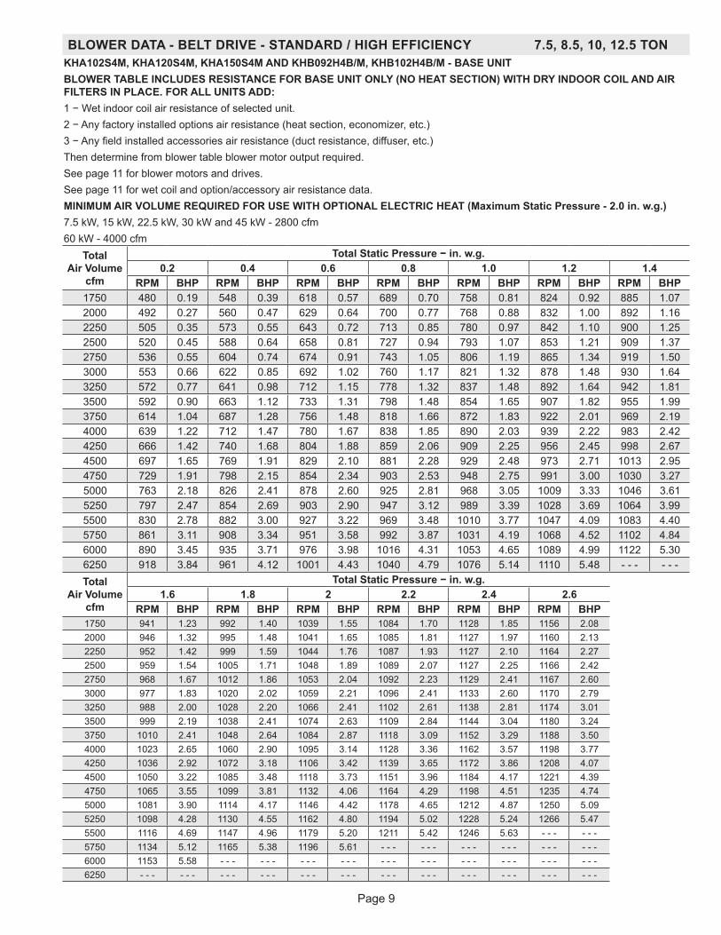
BLOWER DATA - BELT DRIVE - STANDARD / HIGH EFFICIENCY 7.5, 8.5, 10, 12.5 TONKHA102S4M, KHA120S4M, KHA150S4M AND KHB092H4B/M, KHB102H4B/M - BASE UNITBLOWER TABLE INCLUDES RESISTANCE FOR BASE UNIT ONLY (NO HEAT SECTION) WITH DRY INDOOR COIL AND AIR FILTERS IN PLACE. FOR ALL UNITS ADD:1 − Wet indoor coil air resistance of selected unit.2 − Any factory installed options air resistance (heat section, economizer, etc.)3 − Any field installed accessories air resistance (duct resistance, diffuser, etc.)Then determine from blower table blower motor output required.See page 11 for blower motors and drives.See page 11 for wet coil and option/accessory air resistance data.MINIMUM AIR VOLUME REQUIRED FOR USE WITH OPTIONAL ELECTRIC HEAT (Maximum Static Pressure - 2.0 in. w.g.)7.5 kW, 15 kW, 22.5 kW, 30 kW and 45 kW - 2800 cfm60 kW - 4000 cfm
Total Air Volume
cfm
Total Static Pressure − in. w.g.0.2 0.4 0.6 0.8 1.0 1.2 1.4
RPM BHP RPM BHP RPM BHP RPM BHP RPM BHP RPM BHP RPM BHP1750 480 0.19 548 0.39 618 0.57 689 0.70 758 0.81 824 0.92 885 1.072000 492 0.27 560 0.47 629 0.64 700 0.77 768 0.88 832 1.00 892 1.162250 505 0.35 573 0.55 643 0.72 713 0.85 780 0.97 842 1.10 900 1.252500 520 0.45 588 0.64 658 0.81 727 0.94 793 1.07 853 1.21 909 1.372750 536 0.55 604 0.74 674 0.91 743 1.05 806 1.19 865 1.34 919 1.503000 553 0.66 622 0.85 692 1.02 760 1.17 821 1.32 878 1.48 930 1.643250 572 0.77 641 0.98 712 1.15 778 1.32 837 1.48 892 1.64 942 1.813500 592 0.90 663 1.12 733 1.31 798 1.48 854 1.65 907 1.82 955 1.993750 614 1.04 687 1.28 756 1.48 818 1.66 872 1.83 922 2.01 969 2.194000 639 1.22 712 1.47 780 1.67 838 1.85 890 2.03 939 2.22 983 2.424250 666 1.42 740 1.68 804 1.88 859 2.06 909 2.25 956 2.45 998 2.674500 697 1.65 769 1.91 829 2.10 881 2.28 929 2.48 973 2.71 1013 2.954750 729 1.91 798 2.15 854 2.34 903 2.53 948 2.75 991 3.00 1030 3.275000 763 2.18 826 2.41 878 2.60 925 2.81 968 3.05 1009 3.33 1046 3.615250 797 2.47 854 2.69 903 2.90 947 3.12 989 3.39 1028 3.69 1064 3.995500 830 2.78 882 3.00 927 3.22 969 3.48 1010 3.77 1047 4.09 1083 4.405750 861 3.11 908 3.34 951 3.58 992 3.87 1031 4.19 1068 4.52 1102 4.846000 890 3.45 935 3.71 976 3.98 1016 4.31 1053 4.65 1089 4.99 1122 5.306250 918 3.84 961 4.12 1001 4.43 1040 4.79 1076 5.14 1110 5.48 - - - - - -Total
Air Volume cfm
Total Static Pressure − in. w.g.1.6 1.8 2 2.2 2.4 2.6
RPM BHP RPM BHP RPM BHP RPM BHP RPM BHP RPM BHP1750 941 1.23 992 1.40 1039 1.55 1084 1.70 1128 1.85 1156 2.082000 946 1.32 995 1.48 1041 1.65 1085 1.81 1127 1.97 1160 2.132250 952 1.42 999 1.59 1044 1.76 1087 1.93 1127 2.10 1164 2.272500 959 1.54 1005 1.71 1048 1.89 1089 2.07 1127 2.25 1166 2.422750 968 1.67 1012 1.86 1053 2.04 1092 2.23 1129 2.41 1167 2.603000 977 1.83 1020 2.02 1059 2.21 1096 2.41 1133 2.60 1170 2.793250 988 2.00 1028 2.20 1066 2.41 1102 2.61 1138 2.81 1174 3.013500 999 2.19 1038 2.41 1074 2.63 1109 2.84 1144 3.04 1180 3.243750 1010 2.41 1048 2.64 1084 2.87 1118 3.09 1152 3.29 1188 3.504000 1023 2.65 1060 2.90 1095 3.14 1128 3.36 1162 3.57 1198 3.774250 1036 2.92 1072 3.18 1106 3.42 1139 3.65 1172 3.86 1208 4.074500 1050 3.22 1085 3.48 1118 3.73 1151 3.96 1184 4.17 1221 4.394750 1065 3.55 1099 3.81 1132 4.06 1164 4.29 1198 4.51 1235 4.745000 1081 3.90 1114 4.17 1146 4.42 1178 4.65 1212 4.87 1250 5.095250 1098 4.28 1130 4.55 1162 4.80 1194 5.02 1228 5.24 1266 5.475500 1116 4.69 1147 4.96 1179 5.20 1211 5.42 1246 5.63 - - - - - -5750 1134 5.12 1165 5.38 1196 5.61 - - - - - - - - - - - - - - - - - -6000 1153 5.58 - - - - - - - - - - - - - - - - - - - - - - - - - - - - - -6250 - - - - - - - - - - - - - - - - - - - - - - - - - - - - - - - - - - - -

Page 10
BLOWER DATA - DIRECT DRIVE - HIGH EFFICIENCY 10 TONKHB122H4E - BASE UNITBLOWER TABLE INCLUDES RESISTANCE FOR BASE UNIT ONLY (NO HEAT SECTION) WITH DRY INDOOR COIL AND AIR FILTERS IN PLACE. FOR ALL UNITS ADD:1 − Wet indoor coil air resistance of selected unit.2 − Any factory installed options air resistance (heat section, economizer, etc.)3 − Any field installed accessories air resistance (duct resistance, diffuser, etc.)See page 11 for wet coil and option/accessory air resistance data.MINIMUM AIR VOLUME REQUIRED FOR USE WITH OPTIONAL ELECTRIC HEAT (Maximum Static Pressure - 2.0 in. w.g.)15 kW, 22.5 kW, 30 kW, 45 kW - 2750 cfm60 kW - 3500 cfm
Total Air Volume
cfm
Total Static Pressure - in. w.g.0.2 0.4 0.6 0.8 1.0 1.2 1.4
RPM Watts RPM Watts RPM Watts RPM Watts RPM Watts RPM Watts RPM Watts1750 711 188 771 279 836 366 905 453 975 544 1044 640 1109 7372000 752 242 812 332 876 420 944 510 1011 606 1075 709 1138 8122250 799 300 860 389 923 479 988 575 1052 678 1113 787 1171 8962500 853 362 914 453 976 548 1038 650 1097 761 1154 877 1209 9902750 914 434 974 529 1033 629 1091 739 1146 858 1199 979 1250 10983000 980 513 1037 614 1092 720 1146 837 1198 961 1247 1088 1295 12153250 1048 598 1101 705 1153 819 1203 941 1251 1071 1298 1206 1343 13433500 1116 693 1166 809 1214 931 1261 1060 1307 1198 1351 1341 1395 14893750 1185 806 1232 931 1277 1063 1322 1201 1365 1348 1407 1499 1448 16574000 1254 937 1299 1072 1341 1214 1383 1363 1424 1518 1464 1679 1503 18444250 1324 1089 1366 1234 1406 1386 1445 1545 1484 1708 1522 1876 1559 20464500 1395 1262 1433 1417 1471 1579 1508 1745 1544 1913 1581 2084 1616 22564750 1465 1455 1501 1619 1536 1787 1571 1957 1606 2128 1641 2299 1675 24705000 1534 1666 1568 1834 1602 2004 1635 2174 1668 2345 1701 2514 1735 26825250 1603 1887 1635 2055 1667 2224 1699 2392 1731 2559 1763 2724 - - - - - -5500 1671 2110 1702 2275 1733 2441 1764 2605 - - - - - - - - - - - - - - - - - -5750 1738 2325 1768 2488 - - - - - - - - - - - - - - - - - - - - - - - - - - - - - -Total
Air Volume cfm
Total Static Pressure - in. w.g.1.6 1.8 2.0 2.2 2.4 2.6
RPM Watts RPM Watts RPM Watts RPM Watts RPM Watts RPM Watts1750 1172 833 1231 932 1287 1039 1340 1156 1391 1283 1442 14262000 1197 913 1253 1019 1306 1135 1357 1261 1407 1398 1457 15472250 1227 1003 1280 1117 1330 1242 1379 1378 1428 1525 1477 16802500 1261 1103 1311 1226 1360 1361 1407 1507 1454 1663 1501 18262750 1299 1219 1347 1350 1394 1494 1440 1649 1485 1813 1530 19823000 1342 1346 1388 1487 1432 1640 1476 1803 1520 1973 1563 21463250 1388 1485 1432 1638 1475 1800 1517 1969 1558 2143 1600 23193500 1437 1643 1479 1805 1519 1975 1560 2148 1600 2325 1640 25023750 1489 1821 1528 1990 1567 2164 1605 2340 1645 2517 1685 26934000 1541 2014 1579 2187 1616 2364 1654 2540 1693 2715 1732 28874250 1596 2218 1632 2393 1668 2569 1705 2742 1743 2913 - - - - - -4500 1652 2429 1687 2603 1722 2775 1759 2944 - - - - - - - - - - - -4750 1709 2641 1743 2811 1778 2979 - - - - - - - - - - - - - - - - - -5000 1768 2850 - - - - - - - - - - - - - - - - - - - - - - - - - - - - - -5250 - - - - - - - - - - - - - - - - - - - - - - - - - - - - - - - - - - - -5500 - - - - - - - - - - - - - - - - - - - - - - - - - - - - - - - - - - - -5750 - - - - - - - - - - - - - - - - - - - - - - - - - - - - - - - - - - - -

Page 11
BLOWER DATA
FACTORY INSTALLED BELT DRIVE KIT SPECIFICATIONSNominal
hpMaximum
hpDrive Kit Number RPM Range
2 2.3 1 590 - 8902 2.3 2 800 - 11052 2.3 3 795 - 11953 3.45 4 730 - 9703 3.45 5 940 - 12003 3.45 6 1015 - 13005 5.75 10 900 - 11355 5.75 11 1040 - 13155 5.75 12 1125 - 1425
NOTE - Using total air volume and system static pressure requirements determine from blower performance tables rpm and motor output required. Maximum usable output of motors furnished are shown. In Canada, nominal motor output is also maximum usable motor output. If motors of comparable output are used, be sure to keep within the service factor limitations outlined on the motor nameplate.NOTE – Units equipped with MSAV® (Multi-Stage Air Volume)option are limited to a motor service factor of 1.0.
POWER EXHAUST FAN PERFORMANCE Return Air System Static Pressure Air Volume Exhausted
in. w.g. cfm 0 3175
0.05 29550.10 26850.15 24100.20 21650.25 19200.30 14200.35 1200
FACTORY INSTALLED OPTIONS/FIELD INSTALLED ACCESSORY AIR RESISTANCE - in. w.g.
Air Volume cfm
Wet Indoor CoilElectric
Heat EconomizerFilters
Return Air Adaptor PlateKHA092 KHA 102,120,150
KHB 092,102,122 MERV 8 MERV 13
1750 0.03 0.04 0.03 0.05 0.01 0.03 0.00
2000 0.04 0.05 0.03 0.06 0.01 0.03 0.00
2250 0.05 0.06 0.04 0.08 0.01 0.04 0.00
2500 0.05 0.07 0.04 0.11 0.01 0.05 0.00
2750 0.06 0.08 0.05 0.12 0.02 0.05 0.00
3000 0.07 0.10 0.06 0.13 0.02 0.06 0.02
3250 0.08 0.11 0.06 0.15 0.02 0.06 0.02
3500 0.09 0.12 0.09 0.15 0.03 0.07 0.04
3750 0.10 0.14 0.09 0.15 0.03 0.08 0.07
4000 0.11 0.15 0.09 0.19 0.04 0.08 0.09
4250 0.13 0.17 0.13 0.19 0.04 0.09 0.11
4500 0.14 0.19 0.14 0.22 0.04 0.09 0.12
4750 0.15 0.20 0.17 0.25 0.05 0.10 0.16
5000 0.16 0.22 0.20 0.29 0.06 0.10 0.18
5250 0.17 0.24 0.22 0.32 0.06 0.11 0.19
5500 0.19 0.25 0.25 0.34 0.07 0.12 0.22
5750 0.20 0.27 0.31 0.45 0.07 0.12 0.25
6000 0.22 0.29 0.33 0.52 0.08 0.13 0.27

Page 12
BLOWER DATA
CEILING DIFFUSERS AIR RESISTANCE - in. w.g.RTD11 Step-Down Diffuser
FD11 Flush DiffuserUnit Size Air Volume
cfm 2 Ends Open 1 Side, 2 Ends Open
All Ends & Sides Open
092 Models
2400 0.21 0.18 0.15 0.142600 0.24 0.21 0.18 0.172800 0.27 0.24 0.21 0.203000 0.32 0.29 0.25 0.253200 0.41 0.37 0.32 0.313400 0.50 0.45 0.39 0.373600 0.61 0.54 0.48 0.443800 0.73 0.63 0.57 0.51
102,120 & 122 Models
3600 0.36 0.28 0.23 0.153800 0.40 0.32 0.26 0.184000 0.44 0.36 0.29 0.214200 0.49 0.40 0.33 0.244400 0.54 0.44 0.37 0.274600 0.60 0.49 0.42 0.314800 0.65 0.53 0.46 0.355000 0.69 0.58 0.50 0.395200 0.75 0.62 0.54 0.43
150 Models
4200 0.22 0.19 0.16 0.104400 0.28 0.24 0.20 0.124600 0.34 0.29 0.24 0.154800 0.40 0.34 0.29 0.195000 0.46 0.39 0.34 0.235200 0.52 0.44 0.39 0.275400 0.58 0.49 0.43 0.315600 0.64 0.54 0.47 0.355800 0.70 0.59 0.51 0.39
CEILING DIFFUSER AIR THROW DATA
Model No.Air Volume
1 Effective Throw RangeRTD11 Step-Down FD11 Flush
cfm ft. ft.
092 Models
2600 24 - 29 19 - 242800 25 - 30 20 - 283000 27 - 33 21 - 293200 28 - 35 22 - 293400 30 - 37 22 - 30
102,120 & 122 Models
3600 25 - 33 22 - 293800 27 - 35 22 - 304000 29- 37 24 - 334200 32 - 40 26 - 354400 34 - 42 28 - 37
150 Models
5600 39 - 49 28 - 375800 42 - 51 29 - 386000 44 - 54 40 - 506200 45 - 55 42 - 516400 46 - 55 43 - 526600 47 - 56 45 - 56
1 Throw is the horizontal or vertical distance an air stream travels on leaving the outlet or diffuser before the maximum velocity is reduced to 50 ft. per minute. Four sides open.

Page 13
ELECTRICAL/ELECTRIC HEAT DATA - STANDARD EFFICIENCY 7.5 TONBELT DRIVE BLOWER - kHa092s41 Voltage - 60hz 208/230V - 3 Ph 460V - 3 Ph 575V - 3 PhCompressor 1 Rated Load Amps 13.1 6.1 4.4
Locked Rotor Amps 83.1 41 33Compressor 2 Rated Load Amps 13.1 6.1 4.4
Locked Rotor Amps 83.1 41 33Outdoor Fan Motors (2)
Full Load Amps 2.4 1.3 1(total) (4.8) (2.6) (2)
Power Exhaust (1) 0.33 HP
Full Load Amps 2.4 1.3 1
Service Outlet 115V GFI (amps) 15 15 20Indoor Blower Motor
Horsepower 2 3 5 2 3 5 2 3 5Full Load Amps 7.5 10.6 16.7 3.4 4.8 7.6 2.7 3.9 6.1
2 Maximum Overcurrent Protection
Unit Only 50 50 60 25 25 30 15 20 20With (1) 0.33 HP
Power Exhaust50 60 70 25 25 30 20 20 25
3 Minimum Circuit Ampacity
Unit Only 42 45 52 20 22 25 15 16 19With (1) 0.33 HP
Power Exhaust45 48 55 22 23 26 16 17 20
ELECTRIC HEAT DATAElectric Heat Voltage 208V 240V 208V 240V 208V 240V 480V 480V 480V 600V 600V 600V2 Maximum
Overcurrent Protection
Unit+ Electric Heat
7.5 kW 70 70 70 70 80 80 35 35 40 25 25 3015 kW 90 90 90 90 100 100 45 45 50 35 35 40
22.5 kW 110 110 110 125 125 125 60 60 60 45 45 5030 kW 125 150 125 150 150 150 70 70 70 60 60 6045 kW 175 200 175 200 175 200 90 90 100 70 70 80
3 Minimum Circuit Ampacity
Unit+ Electric Heat
7.5 kW 62 65 65 68 72 75 32 33 36 24 25 2815 kW 81 87 84 90 91 97 43 44 47 33 34 37
22.5 kW 101 110 104 113 111 120 54 55 59 42 43 4630 kW 120 132 124 136 131 143 65 67 70 51 52 5545 kW 160 178 163 181 170 188 88 89 92 69 70 73
2 Maximum Overcurrent Protection
Unit+ Electric Heat
and (1) 0.33 HP Power Exhaust
7.5 kW 70 70 70 70 80 80 35 35 40 25 30 3015 kW 90 90 90 100 100 100 45 45 50 35 35 40
22.5 kW 110 125 110 125 125 125 60 60 60 45 45 5030 kW 125 150 150 150 150 150 70 70 80 60 60 6045 kW 175 200 175 200 175 200 90 100 100 70 80 80
3 Minimum Circuit Ampacity
Unit+ Electric Heat
and (1) 0.33 HP Power Exhaust
7.5 kW 64 67 67 70 74 77 33 34 37 25 26 2915 kW 84 90 87 93 94 100 44 45 49 34 35 38
22.5 kW 103 112 106 115 113 122 55 57 60 43 44 4730 kW 123 135 126 138 133 145 67 68 71 52 53 5645 kW 162 180 165 183 172 190 89 91 94 70 71 74
ELECTRICAL ACCESSORIESDisconnect 7.5 kW 54W56 54W56 54W56
15 kW 54W57 54W56 54W5622.5 kW 54W57 54W56 54W56
30 kW 54W57 54W56 54W5645 kW Not Available 54W57 54W56
NOTE - All units have a minimum Short Circuit Current Rating (SCCR) of 5000 amps.1 Extremes of operating range are plus and minus 10% of line voltage.2 HACR type breaker or fuse.3 Refer to National or Canadian Electrical Code manual to determine wire, fuse and disconnect size requirements.

Page 14
ELECTRICAL/ELECTRIC HEAT DATA - STANDARD EFFICIENCY 8.5 TONBELT DRIVE BLOWER - kHa102s41 Voltage - 60hz 208/230V - 3 Ph 460V - 3 Ph 575V - 3 PhCompressor 1 Rated Load Amps 14.5 6.3 6
Locked Rotor Amps 98 55 41Compressor 2 Rated Load Amps 14.5 6.3 6
Locked Rotor Amps 98 55 41Outdoor Fan Motors (2)
Full Load Amps 3 1.5 1.2(total) (6) (3) (2.4)
Power Exhaust (1) 0.33 HP
Full Load Amps 2.4 1.3 1
Service Outlet 115V GFI (amps) 15 15 20Indoor Blower Motor
Horsepower 2 3 5 2 3 5 2 3 5Full Load Amps 7.5 10.6 16.7 3.4 4.8 7.6 2.7 3.9 6.1
2 Maximum Overcurrent Protection
Unit Only 60 60 70 25 25 30 20 25 25With (1) 0.33 HP
Power Exhaust60 60 70 25 25 30 25 25 25
3 Minimum Circuit Ampacity
Unit Only 47 50 56 21 22 26 19 20 23With (1) 0.33 HP
Power Exhaust49 52 59 22 24 27 20 21 24
ELECTRIC HEAT DATAElectric Heat Voltage 208V 240V 208V 240V 208V 240V 480V 480V 480V 600V 600V 600V2 Maximum
Overcurrent Protection
Unit+ Electric Heat
7.5 kW 70 70 70 80 80 90 35 35 40 30 30 3515 kW 90 100 90 100 100 110 45 45 50 40 40 45
22.5 kW 110 125 110 125 125 125 60 60 60 50 50 5030 kW 125 150 150 150 150 150 70 70 80 60 60 6045 kW 175 200 175 200 175 200 90 90 100 80 80 80
3 Minimum Circuit Ampacity
Unit+ Electric Heat
7.5 kW 66 69 69 72 76 79 32 34 37 28 29 3215 kW 86 92 89 95 95 101 44 45 48 37 38 41
22.5 kW 105 114 108 117 115 124 55 56 59 46 47 5030 kW 125 137 128 140 135 147 66 68 71 55 56 5945 kW 164 182 167 185 174 192 89 90 93 73 74 77
2 Maximum Overcurrent Protection
Unit+ Electric Heat
and (1) 0.33 HP Power Exhaust
7.5 kW 70 80 80 80 90 90 35 35 40 30 30 3515 kW 90 100 100 100 100 110 45 50 50 40 40 45
22.5 kW 110 125 125 125 125 150 60 60 70 50 50 6030 kW 150 150 150 150 150 150 70 70 80 60 60 6045 kW 175 200 175 200 200 200 90 100 100 80 80 80
3 Minimum Circuit Ampacity
Unit+ Electric Heat
and (1) 0.33 HP Power Exhaust
7.5 kW 69 72 72 75 78 81 34 35 38 29 30 3315 kW 88 94 91 97 98 104 45 46 49 38 39 42
22.5 kW 108 117 111 120 117 126 56 58 61 47 48 5130 kW 127 139 130 142 137 149 67 69 72 56 57 6045 kW 166 184 169 187 176 194 90 91 95 74 75 78
ELECTRICAL ACCESSORIESDisconnect 7.5 kW 54W56 54W56 54W56
15 kW 54W57 54W56 54W5622.5 kW 54W57 54W56 54W56
30 kW 54W57 54W56 54W5645 kW Not Available 54W57 54W56
NOTE - All units have a minimum Short Circuit Current Rating (SCCR) of 5000 amps.1 Extremes of operating range are plus and minus 10% of line voltage.2 HACR type breaker or fuse.3 Refer to National or Canadian Electrical Code manual to determine wire, fuse and disconnect size requirements.

Page 15
ELECTRICAL/ELECTRIC HEAT DATA - STANDARD EFFICIENCY 10 TONBELT DRIVE BLOWER - kHa120s41 Voltage - 60hz 208/230V - 3 Ph 460V - 3 Ph 575V - 3 PhCompressor 1 Rated Load Amps 15.6 7.8 5.8
Locked Rotor Amps 110 52 38.9Compressor 2 Rated Load Amps 15.6 7.8 5.8
Locked Rotor Amps 110 52 38.9Outdoor Fan Motors (2)
Full Load Amps 3 1.5 1.2(total) (6) (3) (2.4)
Power Exhaust (1) 0.33 HP
Full Load Amps 2.4 1.3 1
Service Outlet 115V GFI (amps) 15 15 20Indoor Blower Motor
Horsepower 2 3 5 2 3 5 2 3 5Full Load Amps 7.5 10.6 16.7 3.4 4.8 7.6 2.7 3.9 6.1
2 Maximum Overcurrent Protection
Unit Only 60 60 70 30 30 35 20 25 25With (1) 0.33 HP
Power Exhaust60 60 70 30 30 35 20 25 25
3 Minimum Circuit Ampacity
Unit Only 49 52 59 24 26 29 19 20 22With (1) 0.33 HP
Power Exhaust51 55 61 26 27 30 20 21 23
ELECTRIC HEAT DATAElectric Heat Voltage 208V 240V 208V 240V 208V 240V 480V 480V 480V 600V 600V 600V2 Maximum
Overcurrent Protection
Unit+ Electric Heat
15 kW 90 100 100 100 100 110 50 50 60 40 40 4022.5 kW 110 125 125 125 125 150 60 60 70 50 50 50
30 kW 150 150 150 150 150 150 70 80 80 60 60 6045 kW 175 200 175 200 200 200 100 100 100 80 80 8060 kW 175 200 200 200 200 225 100 100 110 80 80 80
3 Minimum Circuit Ampacity
Unit+ Electric Heat
15 kW 88 94 91 97 98 104 47 48 51 37 38 4022.5 kW 108 117 111 120 117 126 58 60 62 46 47 49
30 kW 127 139 130 142 137 149 70 71 74 55 56 5845 kW 166 184 169 188 176 194 92 94 96 73 74 7660 kW 174 193 177 197 184 203 97 98 101 76 78 80
2 Maximum Overcurrent Protection
Unit+ Electric Heat
and (1) 0.33 HP Power Exhaust
15 kW 100 100 100 100 100 110 50 50 60 40 40 4522.5 kW 110 125 125 125 125 150 60 70 70 50 50 50
30 kW 150 150 150 150 150 175 80 80 80 60 60 6045 kW 175 200 175 200 200 200 100 100 100 80 80 8060 kW 200 200 200 200 200 225 100 100 110 80 80 90
3 Minimum Circuit Ampacity
Unit+ Electric Heat
and (1) 0.33 HP Power Exhaust
15 kW 91 97 94 100 100 106 48 50 53 38 39 4122.5 kW 110 119 113 122 120 129 60 61 64 47 48 50
30 kW 130 142 133 145 139 151 71 72 75 56 57 5945 kW 169 187 172 190 178 196 93 95 98 74 75 7760 kW 177 196 180 199 186 205 98 99 102 77 79 81
ELECTRICAL ACCESSORIESDisconnect 15 kW 54W57 54W56 54W56
22.5 kW 54W57 54W56 54W5630 kW 54W57 54W56 54W5645 kW Not Available 54W57 54W5660 kW Not Available 54W57 54W56
NOTE - All units have a minimum Short Circuit Current Rating (SCCR) of 5000 amps.1 Extremes of operating range are plus and minus 10% of line voltage.2 HACR type breaker or fuse.3 Refer to National or Canadian Electrical Code manual to determine wire, fuse and disconnect size requirements.

Page 16
ELECTRICAL/ELECTRIC HEAT DATA - STANDARD EFFICIENCY 12.5 TONBELT DRIVE BLOWER - KHA150S41 Voltage - 60hz 208/230V - 3 Ph 460V - 3 Ph 575V - 3 PhCompressor 1 Rated Load Amps 19 9.7 7.4
Locked Rotor Amps 123 62 50Compressor 2 Rated Load Amps 19 9.7 7.4
Locked Rotor Amps 123 62 50Outdoor Fan Motors (3)
Full Load Amps 2.4 1.3 1(total) (7.2) (3.9) (3)
Power Exhaust (3) 0.33 HP
Full Load Amps 2.4 1.3 1
Service Outlet 115V GFI (amps) 15 15 20Indoor Blower Motor
Horsepower 2 3 5 2 3 5 2 3 5Full Load Amps 7.5 10.6 16.7 3.4 4.8 7.6 2.7 3.9 6.1
2 Maximum Overcurrent Protection
Unit Only 70 70 80 35 40 40 25 30 30With (1) 0.33 HP
Power Exhaust80 80 90 40 40 45 30 30 35
3 Minimum Circuit Ampacity
Unit Only 58 61 67 30 31 34 23 24 26With (1) 0.33 HP
Power Exhaust65 68 74 34 35 38 26 27 29
ELECTRIC HEAT DATAElectric Heat Voltage 208V 240V 208V 240V 208V 240V 480V 480V 480V 600V 600V 600V2 Maximum
Overcurrent Protection
Unit+ Electric Heat
15 kW 100 110 110 110 110 125 60 60 60 45 45 4522.5 kW 125 150 125 150 150 150 70 70 70 50 60 60
30 kW 150 150 150 175 150 175 80 80 80 60 60 7045 kW 175 200 200 200 200 225 100 100 110 80 80 8060 kW 200 225 200 225 200 225 110 110 110 90 90 90
3 Minimum Circuit Ampacity
Unit+ Electric Heat
15 kW 97 103 100 106 106 112 52 54 56 41 42 4422.5 kW 117 126 120 129 126 135 63 65 68 50 51 53
30 kW 136 148 139 151 145 157 75 76 79 59 60 6245 kW 175 193 178 196 184 202 97 99 101 77 78 8060 kW 183 202 186 205 192 211 102 103 106 81 82 84
2 Maximum Overcurrent Protection
Unit+ Electric Heat
and (1) 0.33 HP Power Exhaust
15 kW 110 110 110 125 125 125 60 60 60 45 45 5022.5 kW 125 150 150 150 150 150 70 70 80 60 60 60
30 kW 150 175 150 175 175 175 80 80 90 70 70 7045 kW 200 200 200 225 200 225 110 110 110 80 90 9060 kW 200 225 200 225 200 225 110 110 110 90 90 90
3 Minimum Circuit Ampacity
Unit+ Electric Heat
and (1) 0.33 HP Power Exhaust
15 kW 104 110 107 113 113 119 56 57 60 44 45 4722.5 kW 124 133 127 136 133 142 67 69 72 53 54 56
30 kW 143 155 146 158 153 165 79 80 83 62 63 6545 kW 182 200 186 204 192 210 101 103 105 80 81 8360 kW 190 209 193 213 199 219 106 107 110 84 85 87
ELECTRICAL ACCESSORIESDisconnect 15 kW 54W57 54W56 54W56
22.5 kW 54W57 54W56 54W5630 kW Not Available 54W56 54W5645 kW Not Available 54W57 54W5760 kW Not Available 54W57 54W57
NOTE - All units have a minimum Short Circuit Current Rating (SCCR) of 5000 amps.1 Extremes of operating range are plus and minus 10% of line voltage.2 HACR type breaker or fuse.3 Refer to National or Canadian Electrical Code manual to determine wire, fuse and disconnect size requirements.

Page 17
ELECTRICAL/ELECTRIC HEAT DATA - HIGH EFFICIENCY 7.5 TONBELT DRIVE BLOWER - kHB092H41 Voltage - 60hz 208/230V - 3 Ph 460V - 3 Ph 575V - 3 PhCompressor 1 Rated Load Amps 13.1 6.1 4.4
Locked Rotor Amps 83.1 41 33Compressor 2 Rated Load Amps 13.1 6.1 4.4
Locked Rotor Amps 83.1 41 33Outdoor Fan Motors (2)
Full Load Amps 2.8 1.4 1.1(total) (5.6) (2.8) (2.2)
Power Exhaust (1) 0.33 HP
Full Load Amps 2.4 1.3 1
Service Outlet 115V GFI (amps) 15 15 20Indoor Blower Motor
Horsepower 2 3 5 2 3 5 2 3 5Full Load Amps 7.5 10.6 16.7 3.4 4.8 7.6 2.7 3.9 6.1
2 Maximum Overcurrent Protection
Unit Only 50 50 60 25 25 30 15 20 20With (1) 0.33 HP
Power Exhaust50 60 70 25 25 30 20 20 25
3 Minimum Circuit Ampacity
Unit Only 43 46 53 20 22 25 15 16 19With (1) 0.33 HP
Power Exhaust45 49 56 22 23 26 16 17 20
ELECTRIC HEAT DATAElectric Heat Voltage 208V 240V 208V 240V 208V 240V 480V 480V 480V 600V 600V 600V2 Maximum
Overcurrent Protection
Unit+ Electric Heat
7.5 kW 70 70 70 70 80 80 35 35 40 25 30 3015 kW 90 90 90 100 100 100 45 45 50 35 35 40
22.5 kW 110 125 110 125 125 125 60 60 60 45 45 5030 kW 125 150 125 150 150 150 70 70 70 60 60 6045 kW 175 200 175 200 175 200 90 90 100 70 80 80
3 Minimum Circuit Ampacity
Unit+ Electric Heat
7.5 kW 63 66 66 69 73 76 32 33 36 24 26 2815 kW 82 88 85 91 92 98 43 44 48 33 35 37
22.5 kW 102 111 105 114 112 121 54 56 59 42 44 4630 kW 121 133 124 136 131 143 66 67 70 51 53 5545 kW 160 178 163 181 170 188 88 89 93 69 71 73
2 Maximum Overcurrent Protection
Unit+ Electric Heat
and (1) 0.33 HP Power Exhaust
7.5 kW 70 70 70 80 80 80 35 35 40 25 30 3015 kW 90 100 90 100 100 110 45 50 50 35 40 40
22.5 kW 110 125 110 125 125 125 60 60 60 45 45 5030 kW 125 150 150 150 150 150 70 70 80 60 60 6045 kW 175 200 175 200 175 200 90 100 100 70 80 80
3 Minimum Circuit Ampacity
Unit+ Electric Heat
and (1) 0.33 HP Power Exhaust
7.5 kW 65 68 68 71 75 78 33 34 38 25 27 2915 kW 85 91 88 94 95 101 44 46 49 34 36 38
22.5 kW 104 113 107 116 114 123 56 57 60 43 45 4730 kW 124 136 127 139 134 146 67 68 71 52 54 5645 kW 163 181 166 184 173 191 89 91 94 70 72 74
ELECTRICAL ACCESSORIESDisconnect 7.5 kW 54W56 54W56 54W56
15 kW 54W57 54W56 54W5622.5 kW 54W57 54W56 54W56
30 kW 54W57 54W56 54W5645 kW Not Available 54W57 54W56
NOTE - All units have a minimum Short Circuit Current Rating (SCCR) of 5000 amps.1 Extremes of operating range are plus and minus 10% of line voltage.2 HACR type breaker or fuse.3 Refer to National or Canadian Electrical Code manual to determine wire, fuse and disconnect size requirements.

Page 18
ELECTRICAL/ELECTRIC HEAT DATA - HIGH EFFICIENCY 8.5 TONBELT DRIVE BLOWER - kHB102H41 Voltage - 60hz 208/230V - 3 Ph 460V - 3 Ph 575V - 3 PhCompressor 1 Rated Load Amps 14.5 6.3 6
Locked Rotor Amps 98 55 41Compressor 2 Rated Load Amps 14.5 6.3 6
Locked Rotor Amps 98 55 41Outdoor Fan Motors (2)
Full Load Amps 2.8 1.4 1.1(total) (5.6) (2.8) (2.2)
Power Exhaust (1) 0.33 HP
Full Load Amps 2.4 1.3 1
Service Outlet 115V GFI (amps) 15 15 20Indoor Blower Motor
Horsepower 2 3 5 2 3 5 2 3 5Full Load Amps 7.5 10.6 16.7 3.4 4.8 7.6 2.7 3.9 6.1
2 Maximum Overcurrent Protection
Unit Only 60 60 70 25 25 30 20 25 25With (1) 0.33 HP
Power Exhaust60 60 70 25 25 30 25 25 25
3 Minimum Circuit Ampacity
Unit Only 46 49 56 21 22 25 19 20 22With (1) 0.33 HP
Power Exhaust49 52 58 22 24 27 20 21 23
ELECTRIC HEAT DATAElectric Heat Voltage 208V 240V 208V 240V 208V 240V 480V 480V 480V 600V 600V 600V2 Maximum
Overcurrent Protection
Unit+ Electric Heat
7.5 kW 70 70 70 80 80 90 35 35 40 30 30 3515 kW 90 100 90 100 100 110 45 45 50 40 40 40
22.5 kW 110 125 110 125 125 125 60 60 60 50 50 5030 kW 125 150 150 150 150 150 70 70 80 60 60 6045 kW 175 200 175 200 175 200 90 90 100 80 80 80
3 Minimum Circuit Ampacity
Unit+ Electric Heat
7.5 kW 66 69 69 72 76 79 32 34 37 28 29 3115 kW 85 91 88 94 95 101 43 45 48 37 38 40
22.5 kW 105 114 108 117 115 124 55 56 59 46 47 4930 kW 124 136 128 140 134 146 66 67 71 55 56 5845 kW 163 182 167 185 173 191 89 90 93 73 74 76
2 Maximum Overcurrent Protection
Unit+ Electric Heat
and (1) 0.33 HP Power Exhaust
7.5 kW 70 80 80 80 90 90 35 35 40 30 30 3515 kW 90 100 100 100 100 110 45 50 50 40 40 45
22.5 kW 110 125 110 125 125 150 60 60 70 50 50 5030 kW 150 150 150 150 150 150 70 70 80 60 60 6045 kW 175 200 175 200 200 200 90 100 100 80 80 80
3 Minimum Circuit Ampacity
Unit+ Electric Heat
and (1) 0.33 HP Power Exhaust
7.5 kW 68 71 71 74 78 81 33 35 38 29 30 3215 kW 88 94 91 97 97 103 45 46 49 38 39 41
22.5 kW 107 116 110 119 117 126 56 57 61 47 48 5030 kW 127 139 130 142 137 149 67 69 72 56 57 5945 kW 166 184 169 187 176 194 90 91 94 74 75 77
ELECTRICAL ACCESSORIESDisconnect 7.5 kW 54W56 54W56 54W56
15 kW 54W57 54W56 54W5622.5 kW 54W57 54W56 54W56
30 kW 54W57 54W56 54W5645 kW Not Available 54W57 54W56
NOTE - All units have a minimum Short Circuit Current Rating (SCCR) of 5000 amps.1 Extremes of operating range are plus and minus 10% of line voltage.2 HACR type breaker or fuse.3 Refer to National or Canadian Electrical Code manual to determine wire, fuse and disconnect size requirements.

Page 19
ELECTRICAL/ELECTRIC HEAT DATA - HIGH EFFICIENCY 10 TONDIRECT DRIVE BLOWER - kHB122H41 Voltage - 60hz 208/230V - 3 Ph 460V - 3 Ph 575V - 3 PhCompressor 1 Rated Load Amps 15.6 7.8 5.8
Locked Rotor Amps 110 52 38.9Compressor 2 Rated Load Amps 15.6 7.8 5.8
Locked Rotor Amps 110 52 38.9Outdoor Fan Motors (3)
Full Load Amps 2.8 1.4 1.1(total) (8.4) (4.2) (3.3)
Power Exhaust (1) 0.33 HP
Full Load Amps 2.4 1.3 1
Service Outlet 115V GFI (amps) 15 15 20Indoor Blower Motor
Horsepower 3.75 3.75 3.75Full Load Amps 8.8 4.3 3.4
2 Maximum Overcurrent Protection
Unit Only 60 30 25With (1) 0.33 HP
Power Exhaust70 35 25
3 Minimum Circuit Ampacity
Unit Only 53 27 20With (1) 0.33 HP
Power Exhaust60 30 23
ELECTRIC HEAT DATAElectric Heat Voltage 208V 240V 480V 600V2 Maximum
Overcurrent Protection
Unit+ Electric Heat
15 kW 100 100 50 4022.5 kW 125 125 60 50
30 kW 150 150 80 6045 kW 175 200 100 8060 kW 200 200 100 80
3 Minimum Circuit Ampacity
Unit+ Electric Heat
15 kW 92 98 49 3822.5 kW 111 120 60 47
30 kW 131 143 72 5645 kW 170 188 94 7460 kW 178 197 99 78
2 Maximum Overcurrent Protection
Unit+ Electric Heat
and (1) 0.33 HP Power Exhaust
15 kW 100 110 60 4522.5 kW 125 150 70 50
30 kW 150 150 80 6045 kW 200 200 100 8060 kW 200 225 110 90
3 Minimum Circuit Ampacity
Unit+ Electric Heat
and (1) 0.33 HP Power Exhaust
15 kW 99 105 53 4122.5 kW 119 128 64 50
30 kW 138 150 76 5945 kW 177 195 98 7760 kW 185 204 103 81
ELECTRICAL ACCESSORIESDisconnect 15 kW 54W57 54W56 54W56
22.5 kW 54W57 54W56 54W5630 kW 54W57 54W56 54W5645 kW Not Available 54W57 54W5760 kW Not Available 54W57 54W57
NOTE - All units have a minimum Short Circuit Current Rating (SCCR) of 5000 amps.1 Extremes of operating range are plus and minus 10% of line voltage.2 HACR type breaker or fuse.3 Refer to National or Canadian Electrical Code manual to determine wire, fuse and disconnect size requirements.

Page 20
ELECTRIC HEAT CAPACITIES
Volts Input
7.5 kW 15 kW 22.5 kW 30 kW 45 kW 60 kWkW
Input Btuh
Output No. of Stages
kW Input
Btuh Output
No. of Stages
kW Input
Btuh Output
No. of Stages
kW Input
Btuh Output
No. of Stages
kW Input
Btuh Output
No. of Stages
kW Input
Btuh Output
No. of Stages
208 5.6 19,100 1 11.3 38,600 1 16.9 57,700 2 22.5 76,800 2 33.8 115,300 2 45.0 153,600 2
220 6.3 21,500 1 12.6 43,000 1 18.9 64,500 2 25.2 86,000 2 37.8 129,000 2 50.4 172,000 2
230 6.9 23,600 1 13.8 47,100 1 20.7 70,700 2 27.5 93,900 2 41.3 141,000 2 55.1 188,000 2
240 7.5 25,600 1 15.0 51,200 1 22.5 76,800 2 30.0 102,400 2 45.0 153,600 2 60.0 204,800 2
440 6.9 21,500 1 12.6 43,000 1 18.9 64,500 2 25.2 86,000 2 37.8 129,000 2 50.4 172,000 2
460 6.9 23,600 1 13.8 47,100 1 20.7 70,700 2 27.5 93,900 2 41.3 141,000 2 55.1 188,000 2
480 7.5 25,600 1 15.0 51,200 1 22.5 76,800 2 30.0 102,400 2 45.0 153,600 2 60.0 204,800 2
550 6.3 21,500 1 12.6 43,000 1 18.9 64,500 2 25.2 86,000 2 37.8 129,000 2 50.4 172,000 2
575 6.9 23,600 1 13.8 47,100 1 20.7 70,700 2 27.5 93,900 2 41.3 141,000 2 55.1 188,000 2
600 7.5 25,600 1 15.0 51,200 1 22.5 76,800 2 30.0 102,400 2 45.0 153,600 2 60.0 204,800 2

Page 21
KHA/KHB PARTS ARRANGEMENT
FIGURE 1
EVAPORATORCOIL
CONDENSERFANS
(3 ON 122/150 UNITS)CONDENSER
COIL
COMPRESSORSCONDENSATE
DRAINFILTERS(FOUR - 20 X 25 X 2”)
ECONOMIZER(OPTIONAL)
BLOWERMOTOR
ELECTRICHEAT
DISCONNECT /CIRCUIT BREAKER
(FACTORY OR FIELDINSTALLED OPTION)
KHA092/102/120/150 CONTROL BOX
FIGURE 2
K1
K2 K3
S42
K65
K10
T1
K8
K132
K133
K58
T18
CMC1
TB1A6
C1C2
C18

Page 22
KHB092/102/122 CONTROL BOX
FIGURE 3
CMC1
TB1
A191
I-UNIT COMPONENTS
The KHA/KHB unit parts arrangement are shown in figure 1.
All L1, L2, and L3 wiring is color coded; L1 is red, L2 is yel
low, and L3 is blue. See wiring diagrams in the back of this
manual for complete call out of components per KHA/KHB
unit.
A-Control Box Components
KHA control box components are shown in figure 2 and
KHB control box components are shown in figure 3. The
control box is located in the upper portion of the com
pressor compartment.
1-Disconnect Switch S48 (field installed)
KHA/KHB units may be equipped with an optional disconnect
switch S48. S48 is a toggle switch, which can be used by the
service technician to disconnect power to the unit.
2-Transformer T1
All KHA/KHB series units use a single line voltage to
24VAC transformer mounted in the control box. Trans
former supplies power to CMC1 and control circuits in
the unit. The transformer is rated at 70VA and is pro
tected by a 3.5 amp circuit breaker (CB8). The 208/230
(Y) voltage transform
ers use two primary
voltage taps as shown
in figure 4, while 460
(G) and 575 (J) voltage
transformers use a
single primary voltage
tap.
3-Transformer T18T18 is a single line voltage to 24VAC transformer used in all
KHA/KHB units. T18 is identical to T1 and is protected by a
3.5 amp circuit breaker (CB18). T18 provides 24VAC to K1
and K2 coil and reversing valve L1 and L2 (via K58-1 con
tacts).
4-Outdoor Fan Capacitor C1, C2, and C18(KHA Only)
Fan capacitors C1, C2, and C18 are 370V/10MF capacitors
used to assist in the start up of condenser fan motors B4, B5,
and B21. Capacitor ratings will be on outdoor fan motor
nameplate.
FIGURE 4
RED230 VOLTS
208 VOLTS
PRIMARY
SECONDARY
208/230V TRANSFORMER

Page 23
5-Compressor Contactor K1 & K2All compressor contactors are three‐pole‐double‐break
contactors with a 24VAC coil. In all KHA/KHB units, K1and
K2 energize compressors B1 and B2 respectively in re
sponse to first or second stage cooling demands. For
KHB units, the auxiliary contacts are attached that disable
the crankcase heaters when compressor is energized. On
KHA CE M-volt units, contactor is CE approved by
manufacturer (Siemens). See figure 5.
FIGURE 5
CONTACTOR
6-Blower Contactor K3
Blower contactor K3, used in all KHA/KHB CAV units, is a
three‐pole‐double‐break contactor with a 24VAC coil used to
energize the indoor blower motor B3 in response to blower de
mand. K3 is energized by a thermostat cooling demand. On
M-volt KHA CE units, the contactor is CE approved by
manufacturer (Siemens). See figure 5.
7-Outdoor Fan Relay K10
Outdoor fan relay K10 is a DPDT relay with a 24VAC coil. K10
energizes condenser fan motors B4, B5, and B21 (KHA150
and KHB122 only) in response to a W1 heating or Y1 or Y2
cooling demand.
8-Power Exhaust Relay K65 (PED units)
Power exhaust relay K65 is a N.O. DPDT relay with a
24VAC coil. K65 is used in all KHA/KHB units equipped with
the optional power exhaust dampers. K65 is energized by
the economizer control panel (A6), after the economizer
dampers reach 50% open (adjustable on control A6).
When K65 closes, the exhaust fan B10 is energized.
9-Compressor On Relays (K132 & K133)
K132 and K133 are two-pole relays with a 24V coil used
to energize compressor contactor coils. K1 is energized
by K132 with a Y1 demand. K2 is energized by K133 with
a Y2 demand. Both K1 and K2 are energized by K132
and K133 with a W1 demand.
10-Transfer Relay (K8)
K8 is a three-pole relay with a 24V coil used to de-energize
the reversing valve during a heating demand. On a first-
stage demand K8-1 closes de-energizing the reversing
valve. K8-2 closes energizing Y1 on the CMC1 board.
Without K8 the reversing valve would remain energized at
all times.
11-Low Ambient Kit Relay (K58)
Low ambient relay K58 is a DPDT relay with a 24V coil en
ergized by a CMC1 output in the heating cycle. K58-1
closes to allow power to reversing valves L1 and L2. K58-2
closes to bypass S11 and S84. This allows the fan to oper
ate during the heating demand and cycle during the cooling
demand.
12-Blower Motor Overload Relay Switch
(S42)
The blower motor overload relay is used in all units
equipped with high efficiency motors. The relay (S42) is
connected in line with the blower motor to monitor the cur
rent flow to the motor. When the relay senses and overload
condition, a set of normally closed contacts open to de-en
ergize 24VAC power T1 transformer.
13-Terminal Block (TB1)
TB1 provides 24VAC field connections. All indoor ther
mostat connections are connected to TB1 located in the
control box.
14-Compressor Overload Relays S176, S177
(M-volt CE units)Relays are wired in series with the appropriate compres
sor contactor and monitor the current flow to the compres
sor motor. When the relay senses an overload condition,
N.C. contacts open to de-energize the compressor. Re
lays are manufactured by Siemens; see figure 6.
FIGURE 6
COMPRESSOR OVERLOAD RELAYS
SET RELAYSTO MAXIMUMOVERLOAD
SETTING
15-Enthalpy Control (A6)
Refer to description in economizer section.

Page 24
16-Defrost Control Board CMC1 29M01
The defrost thermostat, defrost pressure switch and the de
frost control work together to ensure that the heat pump
outdoor coil does not ice excessively during the heating
mode.
Compressor Accumulated Run-Time Interval
The defrost control will not energize a defrost cycle unless
the unit has been operating in heating mode for an accumu
lated 60 minutes (default). The run time interval can be
changed by moving the jumper on the CMC board timing
pins. See figure 7.
The defrost interval can be adjusted to 30, 60, or 90 min
utes. The defrost timing jumper is factory-installed to pro
vide a 60-minute defrost interval. If the timing selector
jumper is not in place, the control defaults to a 90-minute
defrost interval.
Defrost Test Option
A TEST option is provided for troubleshooting. The TEST
mode may be started any time the unit is in the heating
mode and the defrost thermostat is closed or jumpered. If
the timing jumper is in the TEST position at power‐up, the
defrost control will ignore the test pins. When the jumper is
placed across the TEST pins for two seconds, the control
will enter the defrost mode. If the jumper is removed before
an additional 5-second period has elapsed (7 seconds to
tal), the unit will remain in defrost mode until the defrost
pressure switch opens or 14 minutes have passed. If the
jumper is not removed until after the additional 5-second
period has elapsed, the defrost will terminate and the test
option will not function again until the jumper is removed
and re-applied.
Diagnostic LEDs
The defrost board uses two LEDs for diagnostics. TheLEDs flash a sequence according to the condition.
TABLE 1
Defrost Control Board Diagnostic LED
Indicates LED 1 LED 2
Normal operation / power to board
Synchronized Flashwith LED 2
SynchronizedFlash with LED 1
Board failure /no power
Off Off
Board failure On On
Pressure switch open Flash On
DEFROST CONTROL BOARD CMC1
90test
60 30
TIMINGJUMPER
TIMING PINS(SECONDS)
24V
TERMINAL
STRIP
DIAGNOSTIC
LEDs
FIGURE 7

Page 25
17-Defrost Control Board CMC1 100269-05
The defrost system includes a defrost thermostat and a defrost control.
DEFROST THERMOSTAT
The defrost thermostat is located on the liquid line betweenthe check/expansion valve and the distributor. When thedefrost thermostat senses 42°F (5.5°C) or cooler, its contacts close and send a signal to the defrost control to startthe defrost timing. It also terminates defrost when the liquidline warms up to 70°F (21°C).
DEFROST CONTROL (CMC1)
The defrost control includes the combined functions of atime/temperature defrost control, defrost relay, time delay,diagnostic LEDs, and a terminal strip for field wiring connections.
The control provides automatic switching from normalheating operation to defrost mode and back. During compressor cycle (defrost thermostat is closed, calling for defrost), the control accumulates compressor run times at 30,60, or 90 minute field adjustable intervals. If the defrostthermostat is closed when the selected compressor runtime interval ends, the defrost relay is energized and defrost begins.
Defrost Control Timing Pins (P1)
Each timing pin selection provides a different accumulated compressor run time period for one defrost cycle.This time period must occur before a defrost cycle is initiated. The defrost interval can be adjusted to 30 (T1), 60(T2), or 90 (T3) minutes (see figure 8). The maximum defrost period is 14 minutes and cannot be adjusted. Factory default is 90 minutes
If the timing selector jumper is missing, the defrost control defaults to a 90-minute defrost interval.
24V TERMINAL STRIPCONNECTIONS
DIAGNOSTIC LEDS
HIGH PRESSURE SWITCH
TEST PINS
FIELD SELECTTIMING PINS
REVERSING VALVE
DEFROST THERMOSTAT
LOW PRESSURE SWITCH
COMPRESSOR DELAY PINS
S4
S87
SERVICE LIGHT CONNECTIONS
FIGURE 8

Page 26
Test Mode
The TEST mode is activated by removing the jumper on thedefrost termination pins (30, 60 or 90) and placing thejumper on the TEST pins after 24VAC is applied to the control. The low pressure input is ignored in TEST mode.
IMPORTANTThe TEST pins are ignored and the TEST function islocked out:
� If the jumper is applied on the TEST pin before
24VAC is applied to the control.
� If there is a jumper on the 30 or 60 minute defrost ter
mination pins.
Bypass-Anti-Short Cycle Delay
The Y1 input must be active ON, the high pressure switchmust be closed or a jumper must be installed on the highpressure terminals of the control.
Initiate a Forced Defrost
The Y1 input must be active ON, the high pressure switchmust be closed or a jumper must be installed on the highpressure terminals of the control, the defrost thermostat must be closed or a jumper must be placed across the DFterminals on the control and the O terminals must not have24VAC (no power to reversing valve) before control willenter into a force defrost.
Test Mode Sequence
Using the defrost termination pin, short the TEST pins for aperiod of two seconds:
� Clear timed lockout / or pressure switch lockout func
tion.
� Enter defrost mode
After entering forced defrost, if the jumper is removed before 5 seconds has elapsed, the unit will remain in forceddefrost mode until defrost thermostat opens or terminatedon maximum defrost time (14 minutes). If the jumper is notremoved, once 5 seconds has elapsed (7 seconds total),the unit will terminate defrost and return to heat mode. TheTEST mode will then be lockedout and no further TESTmode operation will be executed until the jumper on theTEST pins is removed and reapplied to the applicable defrost termination pins.
IMPORTANTNOTE - After testing has been completed, properly reposition test jumper across desired timing pins.
Compressor Delay (P5)
The 10026905 control, with the 30 second field selectabledelay, is active when the pins are jumpered. This featurehelps reduce occasional sounds that may occur while theunit is cycling In and Out of the defrost mode.
NOTE — The 30‐second compressor feature is ignoredwhen jumper is installed on TEST pins.
Compressor Anti-Short-Cycle Delay
The timed-off delay is five minutes long. The delay helpsprotect the compressor from short-cycling in case the power to the unit is interrupted or a pressure switch opens. Thedelay is bypassed by placing the timer select jumper acrossthe TEST pins for 0.5 seconds.
NOTE - The defrost control must have a thermostat demand for the bypass function to operate
Pressure Switch Circuits
The defrost control includes two pressure switch circuits.The factory-installed high pressure switch (S4) wires areconnected to the defrost control's HI PS terminals (figure 8).The defrost control also includes LO PS terminals to accommodate an optional field-provided low (or loss‐of‐charge)pressure switch.
During a single thermostat cycle, the defrost control willlock out the unit after the fifth time that the circuit is interrupted by any pressure switch that is wired to the defrostcontrol. In addition, the diagnostic LEDs will indicate apressure switch lockout after the fifth occurrence of anopen pressure switch (see table 2). The unit will remainlocked out until 24V power from the indoor unit is brokenthen remade to the control or until the jumper is applied tothe TEST pins for 0.5 seconds.
NOTE - The defrost control ignores input from the low pressure switch terminals during the TEST mode, during thedefrost cycle, during the 90-second start-up period, and forthe first 90 seconds each time the reversing valve switchesheat/cool modes. If the TEST pins are jumpered and the5-minute delay is being bypassed, the LO PS terminalsignal is not ignored during the 90-second start-upperiod.
DIAGNOSTIC LEDS
The defrost control uses two LEDs for diagnostics. TheLEDs flash a specific sequence according to the diagnosis.See table 2.
TABLE 2
DS2 Green DS1 Red Condition
OFF OFF Power problem
Simultaneous Slow Flash Normal operation
Alternating Slow Flash 5-min. anti-short cycle delay
OFF Slow Flash Low Pressure Fault
OFF ON Low Pressure Lockout
Slow Flash OFF High Pressure Fault
ON OFF High Pressure Lockout

Page 27
18-Fan Control Board A191 (KHB)
Fan control board A191 (figure 9) provides indoor blower
and outdoor fan control for all KHB units. For indoor blower
control, the A191 can provide predefined two speed level
output for different running mode if a belt drive blower with
inverter is applicable. The A191 can provide 0 to 10 Volt
output so that airflow can be adjusted for different running
mode if an EBM blower is application. For outdoor fan con
trol, the A191 can provide four-speed level PWM output for
different running mode and low ambient condition. A191
has on-board dip switch setting to configure the unit size.
The A191 provides minimum damper position operation for
economizer. The A191 includes LVC2 functionality.
TABLE 3Fan Control Board Diagnostic LED
Mode of Operation LED
Normal Operation Blink at 1 second rate
Power to board but aproblem exists
Dim and no blink
Board Failure / No Power Off
FIGURE 9
FCB (A191) FAN CONTROL BOARD
VENTILATIONSPEED SWITCH
LOW SPEEDDAMPER MINIMUMPOSITION POTEN
TIOMETERHIGH SPEED
DAMPER MINIMUMPOSITION POTEN
TIOMETER
POWERLED
FIGURE 10
FCB BOARD TERMINAL DESIGNATIONS
24VACTHERMOSTAT INPUTS;
H1 HEADER
24VACVFD INPUTS;H2 HEADER
KHB Fan Control Board Run Test
DIP Switch Setup Check-Out Procedure
The unit configuration can be setup with the dip switch. See
figure 11. There are two ways to approve dip switch set
up— by checking OD fan PWM signal and by checking OD
fan speed (RPM) combined with ID blower speed checking.
Either way should indicate the dip switch settings. See ta
bles 4, 5 and NO TAG.
FIGURE 11
FCB (A191) DIP SWITCH SETTINGS
1 2 3 4 5 6
KHB092H4B
1 2 3 4 5 6
KHB092H4M
1 2 3 4 5 6
KHB102H4B
1 2 3 4 5 6
KHB102H4M
1 2 3 4 5 6
KHB122H4E
TABLE 4
OutputTerminals
VoltageID BlowerOperation
RL-SD 1VDCLow Speed
RH-SD 24VDC
RL-SD 24VDCHigh Speed
RH-SD 1VDC
Note - 24V is a reference number. It may vary from 18V to
24V.

Page 28
TABLE 5OD Fan PWM Signal / ID Blower Speed
Unit Configuration OD Fan PWM FullLoad
OD Fan PWM PartLoad
ID Blower Out PutFull Load*
ID Blower OutputPart Load*
KHB092 CAV 75% 40% High Speed High Speed
KHB092 MSAV w Inverter 75% 40% High Sped Low Speed
KHB102 CAV 80% 50% High Speed High Speed
KHB102 MSAV w Inverter 80% 50% High Speed Low Speed
KHB122 MSAV w EBM 75% 40% 6.33 Volt (default) 4.7 Volt (default)
*ID blower output with inverter. Measure the IDB output--6.33 Volt for full load by default, 4.7 Volt for part load by default. ID blower voltage output may
change depending on the potentiometer setting.
19- VFD Phase Protection Monitor (A42)A42 is an optional 3-phase line monitor that protects
against phase loss, phase reverse and phase unbalance.
The unit will not start if phase is incorrect. and will shut
down if proper phasing is interrupted.
20- Terminal Block TB13
TB13 provides power connection for KHA/KHB units with
belt drive blowers driven by inverter and KHB units with di
rect drive blowers.

Page 29
PLUMBING COMPONENTSKHA/KHB092, KHA/KHB102 and KHA120
FIGURE 12
COMPRESSOR DETAILfront view
B2 B1
L1
L2
S7
S4
S104
S46
OUTDOORCOILS
INDOORCOIL
COMPRESSOR 1COMPRESSOR 2
DRIERS

Page 30
PLUMBING COMPONENTSKHA150 and KHB122
FIGURE 13
COMPRESSOR DETAILfront view
B2 B1
L1
L2
S7
S4
S104
S46
OUTDOORCOILS
INDOORCOIL
COMPRESSOR 1COMPRESSOR 2
DRIERS
ACCUMULATORS

Page 31
B-Cooling Components
KHA/KHB units use independent cooling circuits consisting
of separate compressors, outdoor coils and indoor coil
(with 2 separate stages). See figure 12 for 092, 102, and
120 units and figure 13 for 122 and 150. Units are equipped
with two draw-through type condenser fans. All 092, 102,
120 and 150 units are equipped with belt‐drive blowers and
KHB122 is equipped with direct-drive blower which draw
air across the indoor coil during unit operation.
Cooling may be supplemented by a factory‐ or field‐
installed economizer. The indoor coils are slab type and are
stacked. Each indoor coil uses a thermostatic expansion
valve as the primary expansion device. Each indoor coil is
also equipped with enhanced fins and rifled tubing. In all
units each compressor is protected by a freezestat (on
each indoor coil) and a high pressure switch (S4, S7). Low
ambient switches (S11, S84) are available as an option for
additional compressor protection. Low ambient switch
(S185) is available as an option for KHB units only.
1-Compressors B1 and B2
All KHA/KHB092/150 units use two scroll compressors. All
compressors are equipped with independent cooling cir
cuits. Compressor capacity may vary from stage to stage. In
all cases, the capacity of each compressor is added to reach
the total capacity of the unit. See “SPECIFICATIONS” and
“ELECTRICAL DATA” (table of contents) or compressor
nameplate for compressor specifications.
WARNINGElectrical shock hazard. Compressor must begrounded. Do not operate without protective coverover terminals. Disconnect power before removingprotective cover. Discharge capacitors before servicing unit. Failure to follow these precautions couldcause electrical shock resulting in injury or death.
Each compressor is energized by a corresponding com
pressor contactor.
NOTE-Refer to the wiring diagram section for specific unit
operation.
IMPORTANTSome scroll compressors have an internal vacuumprotector that will unload scrolls when suctionpressure goes below 20 psig. A hissing sound willbe heard when the compressor is running unloaded. Protector will reset when low pressure insystem rises above 40 psig. DO NOT REPLACECOMPRESSOR.
2-Freezestats S49 and S50
Each unit is equipped with a low temperature switch (freezes
tat) located on the return bend of each indoor coil. S49 (first
circuit) and S50 (second circuit) are located on the cor
responding indoor coils.
Each freezestat is a SPST N.C. auto-reset switch which
opens at 29°F + 3°F (‐1.7°C + 1.7°C) on a temperature drop
and closes at 58°F + 4°F (14.4°C + 2.2°C) on a tempera
ture rise. To prevent coil icing, freezestats open during
compressor operation to temporarily disable the re
spective compressor until the coil warms sufficiently to
melt any accumulated frost.
If the freezestats are tripping frequently due to coil icing, check
the unit charge, airflow and filters before allowing unit back in
operation. Make sure to eliminate conditions which might pro
mote indoor coil ice buildup.
3-High Pressure Switches S4 and S7
The high pressure switches is a manual reset SPST N.C.
switch which opens on a pressure rise. The switch is located in
the compressor discharge line and is wired in series with the
compressor contactor coil.
S4 (first circuit) and S7 (second circuit) are wired in series with
the respective compressor contactor coils.
When discharge pressure rises to 640 ± 10 psig (4412 ±
69 kPa) (indicating a problem in the system) the switch
opens and the respective compressor is de-energized
(the economizer can continue to operate).
4-Low Ambient Switches S11, S84 & S185
(optional)
The low ambient switch is an auto‐reset SPST N.O. pres
sure switch which allows for mechanical cooling opera
tion at low outdoor temperatures. In all models a switch
is located in each liquid line prior to the indoor coil sec
tion.
In the KHA/KHB092/150, S11 and S84 wired in parallel are
wired in series with outdoor fan relay K10.
When liquid pressure rises to 450 ± 10 psig (3102 ± 69
kPa), the switch closes and the condenser fans are ener
gized. When liquid pressure on both refrigerant circuit
drops to 240 ± 10 psig (1655 ± 69 kPa), the switch opens
and the condenser fans are de-energized. This intermittent
fan operation results in higher evaporating temperature al
lowing the system to operate without icing the indoor coil
and losing capacity.
In the KHB units, an extra low ambient switch S185 is wired
in series with outdoor fan relay K10 at stage 1 liquid line.
When liquid pressure at stage 1 rises to 300 +/- 10 psig
(2068+/-69 kPa), switch closes. When liquid pressure on
stage 1 drops to 180+/-10 psig (1241 +/-69 kPa), the switch
opens. When liquid line pressure drops below 240 +/- 10
psig (1655+/-69 kPa) but above 180+/- 10 psig (1241 +/-69
kPa), a low ambient control (A191) energizes the con
denser fans run at 25% PWM. This allows the condenser
fans to run at steady state to help reduce condenser fan cy
cling and improve the fan motor as well as system operat
ing reliability. If condenser fan air temperature keeps drop
ping to certain level, and liquid line pressure drops below
180 +/- 10 psig (1241 +/-69 kPa), the condenser fans will
de-energize. When liquid line pressure rises to 300 +/- 10

Page 32
psig (2068 +/- 69 kPa) , the condenser fans will energize to
25% PWM. Once the pressure switch resets at 450 +/-10
psig (3102 +/-69 kPa) the condenser fans resume back to
normal operation.
5-Reversing Valve L1 and L2
A refrigerant reversing valve with a 24 volt solenoid coil
is used to reverse refrigerant flow during unit operation
in all KHA/KHB units. The reversing valve is connected in
the vapor line of the refrigerant circuit. The reversing valve
coil is energized during cooling demand and during de
frost.
Reversing valve L1 and L2 are controlled by the defrost
control board CMC1 in response to cooling demand or
by defrost.
6-Defrost Pressure Switch S46 and S104
The defrost pressure switch S46 and S104 are auto‐reset
SPST N.C. pressure switches which open on a pressure
rise. All KHA/KHB units are equipped with these switches.
The switches are located on the discharge line. S46 and
S104 are wired in series with the CMC1 control board.
When discharge pressure reaches 450 + 10 psig (3102 �
69 kPa) in either circuit (indicating defrost is completed) the
appropriate switch opens. The switches automatically re
set when pressure in the suction line drops to 300 + 20 psig
(2068 � 138 kPa).
7-Defrost Temperature Switch S6 and S9
Defrost thermostat switches S6 and S9 have S.P.S.T. N.O.
contacts which close on a temperature fall (initiating defrost).
The switches are located on the expansion valve distrib
utor assembly at the inlet to the outdoor coil. The switch
monitors the outdoor coil suction temperature to deter
mine when defrost is needed. When the outdoor coil
suction temperature falls to 35°F + 4°F (1.7°C + 2.2°C)
the switch closes (initiating defrost after minimum run time
of 30, 60, or 90 minutes). When the temperature rises to
60°F + 5°F (15.6°C + 2.8°C) the switch opens.
8-Filter Drier (all units)
KHA/KHB units have a filter drier located in the liquid line of
each refrigerant circuit at the exit of each condenser coil
(outdoor coil in KHA/KHB units). The drier removes contami
nants and moisture from the system.
9-Condenser Fan Motors B4 and B5
See specifications section of this manual for specifications of
condenser fans B4 and B5. All KHA motors are ball bearing
type single-phase motors. All KHB motors are electrical
commutated condenser fan motors (ECM). The ECM mo
tors are wired directly to 230VAC power but do not operate
until a pulse width modulated (PWM) control signal is sent
from A191 fan control board. There are four predefined
PWM output signal with different running mode and low
ambient condition. All condenser fans should run at the
same speed if the indicated PWM signal is issued. The fans
may be removed for servicing and cleaning by removing the
fan grilles.
C-Blower Compartment
The blower compartment in all KHA/KHB092/150 units is
located between the indoor coil and the outdoor coil section.
The blower assembly is accessed by disconnecting the blower
motor and all other plugs and removing the screws in front of
the blower housing. The blower pulls out as shown in figures
14 and 15.
1-Blower Wheels
All KHA092/150 and KHB092/102 units have one 15 in. x 15
in. (381 mm x 381 mm) blower wheel. KHB122 units have di
rect drive blower assembly with backward inclined blower
wheel.
2-Indoor Blower Motor B3
All KHA and KHB092/102 units use three‐phase single‐
speed belt-drive blower motors. The KHB122 model uses
three-phase variable speed direct drive blower motors.
.CFM adjustments are made by adjusting the motor pulley
(sheave).for single speed blower motors. Motors are
equipped with sealed ball bearings. All motor specifications
are listed in the SPECIFICATIONS (table of contents) in the
front of this manual. Units may be equipped with motors
manufactured by various manufacturers, therefore electrical
FLA and LRA specifications will vary. See unit name plate for
information specific to your unit.
OPERATION / ADJUSTMENT
Belt-Driven Supply Air Inverter Units - Units are equipped
with a phase monitor located in the control compartment. The
phase monitor will detect the phasing of incoming power. If the
incoming power is out of phase or if any of the three phases
are lost, the indicating LED on the phase monitor will turn red
and the unit will not start. In normal operation with correct in
coming power phasing, the LED will be green.
Blower Operation
Initiate blower demand at thermostat according to instruc
tions provided with thermostat. Unit will cycle on thermostat
demand. The following steps apply to applications using a
typical electro-mechanical thermostat.
1- Blower operation is manually set at the thermostat sub
base fan switch. With fan switch in ON position, blow
ers will operate continuously.
2- With fan switch in AUTO position, the blowers will cycle
with demand. Blowers and entire unit will be off when
system switch is in OFF position.
Blower Access
The blower assembly is secured to a sliding base which al
lows the entire assembly to be pulled out of the unit. See
figure 14 for belt drive assembly and figure 15 for direct
drive assembly. Follow the steps below.
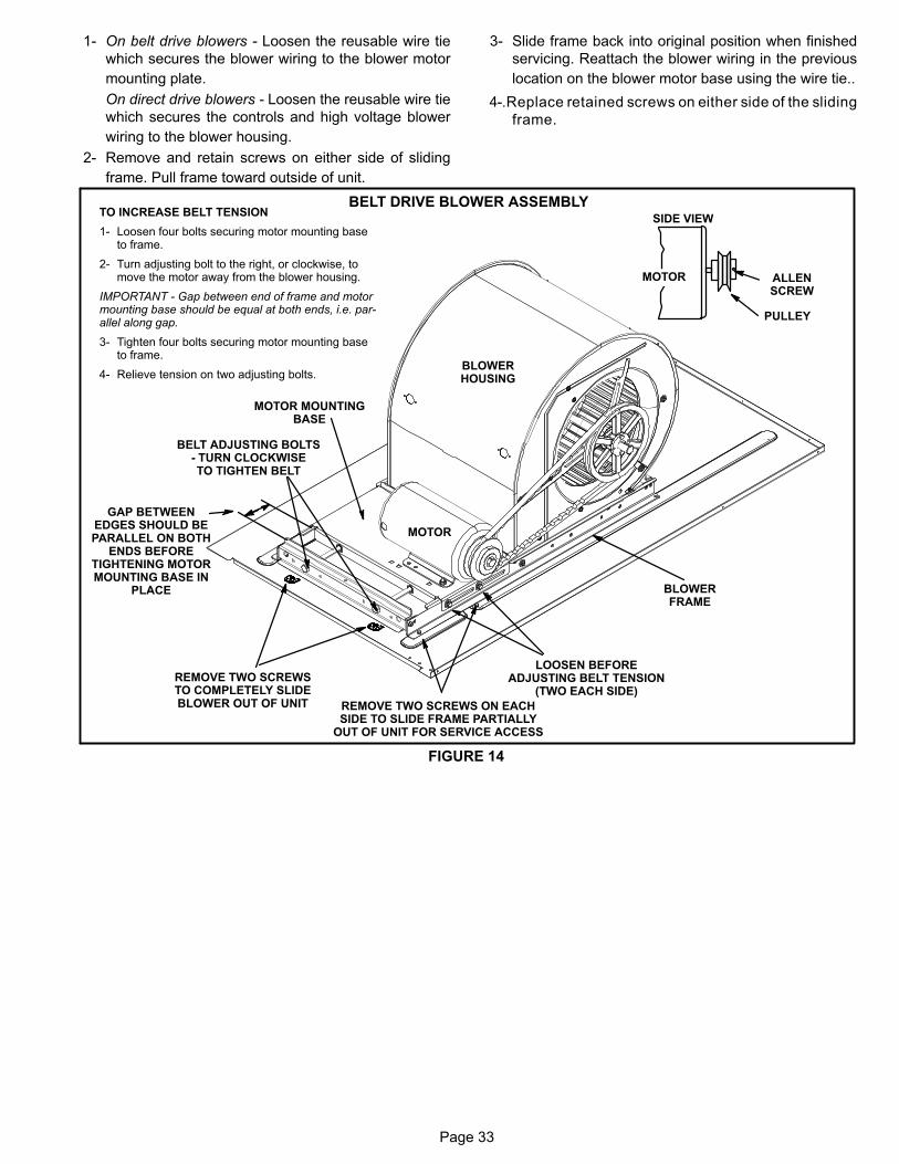
Page 33
1- On belt drive blowers - Loosen the reusable wire tie
which secures the blower wiring to the blower motor
mounting plate.
On direct drive blowers - Loosen the reusable wire tie
which secures the controls and high voltage blower
wiring to the blower housing.
2- Remove and retain screws on either side of sliding
frame. Pull frame toward outside of unit.
3- Slide frame back into original position when finished
servicing. Reattach the blower wiring in the previous
location on the blower motor base using the wire tie..
4-.Replace retained screws on either side of the sliding
frame.
BELT DRIVE BLOWER ASSEMBLY
FIGURE 14
PULLEY
MOTOR
SIDE VIEW
ALLENSCREW
BELT ADJUSTING BOLTS- TURN CLOCKWISETO TIGHTEN BELT
MOTOR MOUNTINGBASE
LOOSEN BEFOREADJUSTING BELT TENSION
(TWO EACH SIDE)
REMOVE TWO SCREWS ON EACHSIDE TO SLIDE FRAME PARTIALLY
OUT OF UNIT FOR SERVICE ACCESS
MOTOR
BLOWERHOUSING
BLOWERFRAME
GAP BETWEENEDGES SHOULD BEPARALLEL ON BOTH
ENDS BEFORETIGHTENING MOTORMOUNTING BASE IN
PLACE
REMOVE TWO SCREWSTO COMPLETELY SLIDEBLOWER OUT OF UNIT
TO INCREASE BELT TENSION
1- Loosen four bolts securing motor mounting baseto frame.
2- Turn adjusting bolt to the right, or clockwise, tomove the motor away from the blower housing.
IMPORTANT - Gap between end of frame and motormounting base should be equal at both ends, i.e. parallel along gap.
3- Tighten four bolts securing motor mounting baseto frame.
4- Relieve tension on two adjusting bolts.

Page 34
DIRECT DRIVE BLOWER ASSEMBLY
FIGURE 15
INLETGRID
REMOVE TWO SCREWSON EACH SIDE TO SLIDEBLOWER OUT OF UNIT
BLOWERHOUSING
BLOWER MOTORSECURED TO THISSIDE OF HOUSING
Determining Unit CFM
IMPORTANT - Belt-driven supply air inverter units are facto
ry-set to run the blower at full speed when there is a blower
(G) demand without a heating or cooling demand. Use the
following procedure to adjust motor pulley to deliver the full
load cooling or heating CFM. See Belt-Drive Inverter Start-
Up in this section to set blower CFM for all modes once the
motor pulley is set.
IMPORTANT - Direct drive variable blower unit CFM is de
termined by the Fan Control board. See Direct Drive Vari
able Speed Start-Up section.
1- The following measurements must be made with a dry
indoor coil. Run blower without a cooling demand.
Measure the indoor blower shaft RPM. Air filters must
be in place when measurements are taken.
2- With all access panels in place, measure static pres
sure external to unit (from supply to return).
3- Refer to blower tables in BLOWER DATA (table of con
tents) in the front of this manual. Use static pressure and
RPM readings to determine unit air volume.
4- The blower RPM can be adjusted at the motor pulley.
Loosen Allen screw and turn adjustable pulley clock
wise to increase CFM. Turn counterclockwise to de
crease CFM. See figure 14. Do not exceed minimum
and maximum number of pulley turns as shown in table
6.
TABLE 6MINIMUM AND MAXIMUM PULLEY ADJUSTMENT
BeltMinimum
Turns Open
Maximum
Turns Open
A Section No minimum 5
B Section 1* 6
*No minimum number of turns open when B belt is used onpulleys 6” O.D. or larger.
Blower Belt Adjustment
Maximum life and wear can be obtained from belts only if
proper pulley alignment and belt tension are main
tained. Tension new belts after a 24-48 hour period of
operation. This will allow belt to stretch and seat
grooves. Make sure blower and motor pulley are aligned as
shown in figure 16.
FIGURE 16
PULLEY ALIGNMENT
BELTBLOWERPULLEY
MOTORPULLEY
NOT ALIGNED
ALIGNED
1- Loosen four bolts securing motor base to mounting
frame. See figure 14.

Page 35
2- To increase belt tension -
Turn adjusting bolt to the right, or clockwise, to move
the motor outward and tighten the belt. This increases
the distance between the blower motor and the blower
housing.
To loosen belt tension -
Turn the adjusting bolt to the left, or counterclockwise
to loosen belt tension.
3- Tighten two bolts on motor pulley side.
IMPORTANT - Align top edges of blower motor base and
mounting frame base parallel before tightening two bolts
on the other side of base. Motor shaft and blower shaft
must be parallel.
4- Tighten two bolts on other side of base.
Check Belt Tension
Overtensioned belts shortens belt and bearing life. Check
belt tension as follows:
1- Measure span length X. See figure 17.
2- Apply perpendicular force to center of span (X) with
enough pressure to deflect belt 1/64” for every inch of
span length or 1.5mm per 100mm of span length.
Example: Deflection distance of a 40” span would be
40/64” or 5/8”.
Example: Deflection distance of a 400mm span would
be 6mm.
3- Measure belt deflection force. For a used belt, the
deflection force should be 5 lbs. (35kPa). A new belt
deflection force should be 7 lbs. (48kPa).
A force below these values indicates an underten
sioned belt. A force above these values indicates an
overtensioned belt.
MEASURE BELT TENSION
FIGURE 17
DEFLECTION 1/64” PER INCH OF SPANOR 1.5mm PER 100mm OF SPAN
FORCE
Belt Drive Inverter Start-Up
A-General
1. Units are available with an optional inverter which pro
vides two blower speeds. The blower will operate at
lower speeds when cooling demand is low and higher
speeds when cooling demand is high. This results in
lower energy consumption.
2. Units will operate at high speed during ventilation
(blower “G” only signal) but can be adjusted to operate
at low speed.
3. Low speed is approximately 2/3 of the full speed RPM.
B-Set Maximum Blower CFM
1. Initiate a blower (G) only signal from the room thermo
stat or control system.
2. Adjust the blower pulley to deliver the full (high speed)
CFM in the typical manner. See Determining Unit CFM
in the Blower Operation and Adjustment section.
C-Set Blower Speed During Ventilation
NOTE - Units equipped a Variable Frequency Drive (VFD)
are designed to operate on balanced, three-phase power.
Operating units on unbalanced three-phase power will re
duce the reliability of all electrical components in the unit.
Unbalanced power is a result of the power delivery system
supplied by the local utility company. Factory-installed in
verters are sized to drive blower motors with an equivalent
current rating using balanced three-phase power. If unbal
anced three-phase power is supplied; the installer must re
place the existing factory-installed inverter with an inverter
that has a higher current rating to allow for the imbalance.
Refer to the installation instructions for additional informa
tion and available replacements.
To save energy during ventilation, the blower speed can be
set to low. This is accomplished by changing the ventilation
speed switch on the VFD (figure 18) or FCB (Figure 19
)control board to “LO”.
Note - On units equipped with an economizer, set damper
minimum position as shown in the next section. After ad
justing the low speed minimum position, the ventilation
speed switch will be in the “LO” position.
D-Set Damper Minimum Position (Units W/ Economizer)
To maintain required minimum ventilation air volumes when
the unit is in the occupied mode, two minimum damper posi
tions must be set. A high and a low speed potentiometer are
provided on the VFD or FCB control board to adjust mini
mum damper position. See figure 18 and 19.
Set High Speed Minimum Position
1. Initiate a blower (G) only AND occupied demand from
the room thermostat or control system.
2. Set the ventilation speed switch on the VFD or FCB
control board to “HI”.
3. Rotate the high speed potentiometer on the VFD or
FCB control board to set the high speed minimum
damper position.
4. Measure the intake air CFM. If the CFM is lower than
the design specified CFM for ventilation air, use the po
tentiometer to increase the damper percent open. If the
CFM is higher than specified, decrease the damper
percent open.

Page 36
Note - Intake air CFM can also be determined using the out
door air temperature, return air temperature and mixed air
temperature. Refer to the economizer or outdoor air
damper installation instructions.
Set Low Speed Minimum Position
1. Initiate a blower (G) only AND occupied demand from
the room thermostat or control system.
2. Set the ventilation speed switch on the VFD or FCB
control board to “LO”.
3. Rotate the low speed potentiometer on the VFD or FCB
control board to set the low speed minimum damper
position.
4. Measure the intake air CFM. If the CFM is lower than
the design specified CFM for ventilation air, use the po
tentiometer to increase the damper percent open. If the
CFM is higher than specified, decrease the damper
percent open.
Note - Intake air CFM can also be determined using the out
door air temperature, return air temperature and mixed air
temperature. Refer to the economizer or outdoor air
damper installation instructions.
FIGURE 18
LVC2 (A183) VFD CONTROL BOARD
VENTILATIONSPEED SWITCH
LOW SPEEDMINIMUM POSITIONPOTENTIOMETER
HIGH SPEEDMINIMUM POSITIONPOTENTIOMETER
POWERLED
Direct Drive Variable Speed Inverter Start-Up
A-General
Units are available with an optional direct drive blower
which can be set at high and low speed. The blower will op
erate at lower speeds when demand is low and higher
speeds when demand is high. This results in lower energy
consumption.
1. Initiate a blower (G) only signal from the room thermo
stat or control system. The blower will operate in high
speed.
2. Measure the blower RPM and static pressure and use
appropriate blower table to calculate supply air CFM.
See Determining Unit CFM in the Blower Operation
and Adjustment section.
3. If the resulting CFM is lower than the desired CFM, ro
tate the fan control board high speed potentiometer
clockwise (or counterclockwise if CFM is too high).
4. Calculate the CFM and adjust potentiometer as need
ed to meet desired CFM
5. Initiate a blower (G) AND first-stage (Y1) cooling signal
from the room thermostat or control system. The blow
er will operate in low speed.
6. Calculate the low speed CFM in the same manner as
the high speed CFM.
7. Adjust low speed potentiometer as needed to meet de
sired CFM.
FIGURE 19
FCB (A191) FAN CONTROL BOARD
VENTILATIONSPEED SWITCH
LOW SPEEDDAMPER MINIMUMPOSITION POTEN
TIOMETERHIGH SPEED
DAMPER MINIMUMPOSITION POTEN
TIOMETER
POWERLED
BLOWER HIGH SPEEDPOTENTIOMETER
BLOWER LOW SPEEDPOTENTIOMETER
C-Set Blower Speed During Ventilation
To save energy during ventilation, the blower speed can be
set to low. This is accomplished by changing the ventilation
speed switch on the FCB control board to “LO”. See figure
19.
Note - On units equipped with an economizer, set damper
minimum position as shown in the next section. After ad
justing the low speed minimum position, the ventilation
speed switch will be in the “LO” position.

Page 37
D-Set Damper Minimum Position (Units W/ Economizer)
To maintain required minimum ventilation air volumes when
the unit is in the occupied mode, two minimum damper posi
tions must be set. A high and a low speed potentiometer are
provided on the FCB control board to adjust minimum
damper position. See figure 19.
Set High Speed Minimum Position
1. Initiate a blower (G) only AND occupied demand from
the room thermostat or control system.
2. Set the ventilation speed switch on the FCB control
board to “HI”.
3. Rotate the high speed potentiometer on the FCB con
trol board to set the high speed minimum damper posi
tion.
4. Measure the intake air CFM. If the CFM is lower than
the design specified CFM for ventilation air, use the po
tentiometer to increase the damper percent open. If the
CFM is higher than specified, decrease the damper
percent open.
Note - Intake air CFM can also be determined using the out
door air temperature, return air temperature and mixed air
temperature. Refer to the economizer or outdoor air
damper installation instructions.
Set Low Speed Minimum Position
1. Initiate a blower (G) only AND occupied demand from
the room thermostat or control system.
2. Set the ventilation speed switch on the FCB control
board to “LO”.
3. Rotate the low speed potentiometer on the FCB control
board to set the low speed minimum damper position.
4. Measure the intake air CFM. If the CFM is lower than
the design specified CFM for ventilation air, use the po
tentiometer to increase the damper percent open. If the
CFM is higher than specified, decrease the damper
percent open.
Note - Intake air CFM can also be determined using the out
door air temperature, return air temperature and mixed air
temperature. Refer to the economizer or outdoor air
damper installation instructions.
Troubleshoot FCB Board (A191)
Refer to wiring diagram sections B (unit), C (control) and D
(economizer) located on inside of unit panels.
1. Inspect the board for damaged components. Replace
the board if damaged components are found.
2. Check all wire connections to board; secure if loose.
3. Check for 24VAC signal at the thermostat blower input
(G to GND terminal). See figure 20.
FIGURE 20
FCB BOARD TERMINAL DESIGNATIONS
24VACTHERMOSTAT INPUTS;
H1 HEADER
24VACH2 HEADER
4. If there is no thermostat signal, troubleshoot back to
ward the thermostat.
5. Check the power LED on the board. See figure 19.
6. The LED should be blinking at a 1-second rate when
operating normally. If the LED is dim and not blink
ing, this indicates power is provided but a problem
exists with the board.
7. If the power LED is not on, check voltage between FCB
terminals PC (H2-1) and SD (H2-5). Voltage should
read 24VAC.
8. If voltage does not read 24VAC, disconnect the H2
header from the FCB terminal block (to make sure the
FCB is not shorting 24VAC supply from terminal strip
TB1). Measure the voltage between the end terminals
on the H2 header. If 24VAC is present, replace the FCB
board.
Troubleshoot LVC2 Board (A183)
Refer to wiring diagram sections B (unit), C (control) and D
(economizer) located on inside of unit panels.
1. Inspect the LVC2 for damaged components. Replace
the LVC2 if damaged components are found.
2. Check all wire connections to LVC2; secure if loose.
3. Check for 24VAC signal at the thermostat blower input
(G to GND terminal). See figure 21.
FIGURE 21
LVC2 BOARD TERMINAL DESIGNATIONS
24VACTHERMOSTAT INPUTS;
H1 HEADER
24VDCVFD INPUTS;H2 HEADER
4. If there is no thermostat signal, troubleshoot back to
ward the thermostat.
5. Check the power LED on the board. See figure 18.

Page 38
6. If the power LED is not on, check voltage between
LVC2 terminals PC (H2-1) and SD (H2-5). Voltage
should read 24VDC.
7. If voltage does not read 24VDC, disconnect the H2
header from the LVC2 VFD inputs terminal block (to
make sure the LVC2 is not shorting 24VDC supply from
the inverter). Measure the voltage between the end ter
minals on the H2 header. If 24VDC is present, replace
the LVC2 board. If no voltage is read, troubleshoot the
VFD.
8. When LVC2 24VAC thermostat blower (G) input and
24VDC power are present, check the LVC2 low and
high speed outputs. The LVC2 uses inverse logic to en
able the blower; 1VDC will be read at the enabled blow
er speed terminal. See table 7.
9. If all inputs are correct and the unit still does not oper
ate as intended, replace LVC2 board.
TABLE 7LVC2 BOARD BLOWER OUTPUTS
OutputTerminals
Voltage Blower Operation
RL-SD 1VDCLow Speed
RH-SD 24VDC
RL-SD 24VDCHigh Speed
RH-SD 1VDC
RL-SD 1VDCIllegal State
(replace board)RH-SD 1VDC
RL-SD 24VDC Blower Off(replace board)RH-SD 24VDC
D-Optional Electric Heat Components
Table 8 shows electric heat fuse ratings. See Options/Ac
cessories section (see table of contents) for KHA/KHB to
EHO match-ups. See Electrical/Electric Heat Data section
(see table of contents) of this manual for electrical ratings
and capacities.
All electric heat sections consist of electric heating ele
ments exposed directly to the air stream. See figure 23.
EHO parts arrangement is shown in figures 23 and 24.
Multiple‐stage elements are sequenced on and off in re
sponse to thermostat demand.
1-Contactors K15, K16
Contactors K15 and K16 are three-pole double-break
contactors located on the electric heat vestibule. All
contactors are equipped with a 24VAC coil. The coils in
the K15 and K16 contactors are energized by a W2
thermostat demand, K9, and DL2. Contactor K15
energizes the first stage heating elements, while K16
energizes the second stage heating elements. On M-volt
units, contactors are CE approved by manufacturer
(Siemens). See figure 5.
2-High Temperature Limits S15 (Primary)
S15 is a SPST N.C. auto‐reset thermostat located on
the back panel of the electric heat section below the
heating elements. S15 is the high temperature limit for
the electric heat section. When S15 opens, indicating a
problem in the system, contactor K15 is de‐energized.
When K15 is de‐energized, first stage and all subse
quent stages of heat are de‐energized. For
EHO102/150 units, the electric heat section thermo
stat is factory set to open at 170�F + 5�F (76�C +
2.8�C) on a temperature rise and automatically reset at
130�F + 6�F (54.4�C + 3.3�C) on a temperature fall.
For EHO100 units, the electric heat section thermostat
is factory set to open at 160�F + 5�F (71.0�C + 2.8�C)
on a temperature rise and automatically reset at 120�F
+ 6�F (49.0�C + 3.3�C) on a temperature fall. The ther
mostat is not adjustable.
3-High Temperature Limit S20, S157, S158, S15, S160 &
S161 (Secondary)
Limits are SPST N.C. manual‐reset thermostat . Like
the primary temperature limit, S20 is wired in series
with the first stage contactor coil (K15) and second
stage contactor coil (K16). When S20 opens, contac
tors (K15, K16) are de‐energized. When the contactors
are de‐energized, first stage and all subsequent
stages of heat are de‐energized. The thermostat is fac
tory set to open at 220�F + 6�F (104�C + 3.3�C) on a
temperature rise and can be manually reset when tem
perature falls below 160�F (71.0�C).
4-Terminal Strip TB2
Terminal strip TB2 is used for single point power installa
tions only. TB2 distributes L1, L2 and L3 power to TB3.
Units with multi-point power connections will not use TB2.
5-Terminal Strip TB3
Electric heat line voltage connections are made to termi
nal strip TB3 located in the upper left corner of the electric
heat vestibule. TB3 distributes power to the electric heat
components.
6-Heating Elements HE1 through HE6
Heating elements are composed of helix wound bare
nichrome wire exposed directly to the air stream. Three
elements are connected in a three‐phase arrange
ment. The elements in 208/230V units are connected
in a “Delta” arrangement. Elements in 460 and 575V
units are connected in “Wye” arrangement. Each stage
is energized independently by the corresponding
contactors located on the electric heat vestibule panel.
Once energized, heat transfer is instantaneous. High
temperature protection is provided by primary and re
dundant high temperature limits and overcurrent
protection is provided by fuses.
7-Fuse F3
Fuse F3 are housed in a fuse block which holds three
fuses. Each F3 fuse is connected in series with each leg of
electric heat. Figure 24 and table 8 show the fuses used
with each electric heat section. For simplicity, the ser
vice manual labels the fuses F3 - 1 through F3 - 4.
8-Unit Fuse Block & Fuse F3 and F4
Three line voltage fuses F4 provide short circuit and
ground fault protection to all cooling components in the
KHA/KHB units with electric heat. The fuses are rated in
accordance with the amperage of the cooling compo
nents.

Page 39
TABLE 8
KHA/KHB ELECTRIC HEAT SECTION FUSE RATING
EHO QUANTITY& SIZE VOLTAGES
FUSE (3 each)
F3 - 1 F3 - 2 F4 - 1 F4 - 2
EHO075-1, 7.5
208/230V 25 Amp 250V ----- -----
460V 15 Amp 600V ----- -----
575V 10 Amp 600V ----- -----
EHO150-1, 15
208/230V 50 Amp 250V ----- -----
460V 25 Amp 600V ----- -----
575V 20 Amp 600V ----- -----
EHO225-1, 22.5
208/230V 50 Amp 250V ----- 25 Amp 250V -----
460V 25 Amp 600V ----- 15 Amp 600V -----
575V 20 Amp 600V ----- 10 Amp 600V -----
EHO300-1, 30
208/230V 50 Amp 250V ----- 50 Amp 250V -----
460V 25 Amp 600V ----- 25 Amp 600V -----
575V 20 Amp 600V ----- 20 Amp 600V -----
EHO450-1, 45
208/230V 50 Amp 250V ----- 60 Amp 250V 60 Amp 250V
460V 25 Amp 600V ----- 50 Amp 600V -----
575V 20 Amp 600V ----- 40 Amp 600V -----
EHO600-1, 60
208/230V 60 Amp 250V 60 Amp 250V 60 Amp 250V 60 Amp 250V
460V 50 Amp 600V ----- 50 Amp 600V -----
575V 40 Amp 600V ----- 40 Amp 600V -----
EHO057-1, 5.7 384V ----- 15 Amp 600V ----- -----
EHO115-1, 15 384V ----- 25 Amp 600V ----- -----
EHO172-1, 17.2 384V 25 Amp 600V ----- 15 Amp 600V -----
EHO230-1, 23.0 384V 25 Amp 600V ----- 25 Amp 600V -----
EHO345-1, 34.5 384V 25 Amp 600V ----- 40 Amp 600V -----
EHO459-1, 45.9 384V 40 Amp 600V ----- 40 Amp 600V -----
ELECTRIC HEAT CONTROL ASSEMBLY
1-Electric Heat Relay K9All KHA/KHB series units with electric heat use an electric
heat relay K9. K9 is a N.O. DPDT pilot relay intended to
electrically isolate the unit's 24V circuit from the electric
heat 24V circuit. K9 is energized by CMC1. K9-1 closes,
energizing timer DL2. K9 is located in the electric heat con
trol assembly. See figure 22.
2-Time Delay DL2
DL2 is a factory-installed solid state timer used in 22.5 to 60
kW electric heat units. DL2 allows staging by providing a
timed-interval between the first and second heating ele
ments. When the timer is energized, the contacts are
delayed for 30 seconds before closing. When the timer is
de-energized, the contacts are delayed 1 second before
opening. DL2 is located in the electric heat control assem
bly. See figure 22. FIGURE 22
ELECTRIC HEAT CONTROL ASSEMBLY
ELECTRIC HEATSECTION
DL2
ELECTRIC HEATCONTROL ASSEMBLY
K9

Page 40
FIGURE 23
EHO 7.5, 15, 22.5, 30, 45, 60KW ELECTRIC HEAT SECTION PARTS ARRANGEMENT
PRIMARY ELECTRICHEAT LIMIT
S15
HEATING ELEMENTSHE1 - HE6
P2CONTROL WIRE
HARNESS
ELECTRIC HEATVESTIBULE
SECONDARYLIMIT S20
ELECTRICHEAT THERMOSTAT
S19
SECONDARYLIMIT S20
SECONDARYLIMIT S20
SECONDARYLIMIT S20
SECONDARYLIMIT S20
SECONDARYLIMIT S20
FUSE F3F3-2
FIGURE 24
ELECTRIC HEAT VESTIBULE PARTS ARRANGEMENTTERMINAL STRIP
(TB3)
FIRST STAGE ELECTRICHEAT CONTACTOR K15
SECOND STAGE ELECTRICHEAT CONTACTOR K16
FUSE F3F3 ‐ 1
FUSE F4F4 ‐ 1
FUSE F4F4 ‐ 2

Page 41
II-PLACEMENT AND INSTALLATION
Make sure the unit is installed in accordance with the
installation instructions and all applicable codes. See
accessories section for conditions requiring use of the
optional roof mounting frame (LARMF).
III-START UP - OPERATION
Refer to startup directions and refer closely to the unit wir
ing diagram when servicing. See unit nameplate for mini
mum circuit ampacity and maximum fuse size.
A-Preliminary and Seasonal Checks
1- Make sure the unit is installed in accordance with the
installation instructions and applicable codes.
2- Inspect all electrical wiring, both field and factory installed
for loose connections. Tighten as required. Refer to unit
diagram located on inside of unit control box cover.
3- Check to ensure that refrigerant lines are in good
condition and do not rub against the cabinet or other
refrigerant lines.
4- Check voltage at the disconnect switch. Voltage must
be within the range listed on the nameplate. If not,
consult the power company and have the voltage cor
rected before starting the unit.
5- Recheck voltage and amp draw with unit running. If
voltage is not within range listed on unit nameplate,
stop unit and consult power company. Refer to unit
nameplate for maximum rated load amps.
6- Inspect and adjust blower belt (see section on Blower
Compartment - Blower Belt Adjustment).
B-Heating Start Up
1- Set thermostat or temperature control device to initiate
a first-stage heating demand.
A first-stage heating demand (W1) will energize com
pressors 1 and 2. Both outdoor fans are energized with
a W1 demand.
Note - L1 and L2 reversing valves are de-energized in the
heating mode.
KHA/KHB Units With Optional Electric Heat -
An increased heating demand (W2) will energize elec
tric heat. Electric heat is also energized during the de
frost cycle (W1) to maintain discharge air temperature.
C-Cooling Start Up
IMPORTANTIf unit is equipped with a crankcase heater. Make sureheater is energized 24 hours before unit start-up toprevent compressor damage as a result of slugging.
1- Set thermostat or temperature control device fan
switch to AUTO or ON. Set thermostat or temperature
control device to initiate a first-stage cooling demand.
A first-stage Y1 cooling demand will energize L1 and
L2 reversing valve solenoids and compressor 1. An in
creased cooling demand Y2 will initiate compressor 2.
Units With Optional Economizer -
The optional economizer will start on a first stage (Y1)
cooling demand when outdoor air enthalpy is suitable.
An increased cooling demand (Y2) with the economiz
er open will energize 1 compressor only.
2- Refrigerant circuits are factory charged with refriger
ant. See unit rating plate for correct amount of charge.
3- Units contain two refrigerant circuits or systems. See
figure 25 or 26.
12
KHA092S, 102S, 120S:Y1 Demand = Outdoor Fans 1 & 2 EnergizedY2 Demand = Both fans continue to operate
KHB092H, 102H:Y1 Demand = Outdoor Fan 1 Low Speed and
Outdoor Fan 2 Low SpeedY2 Demand = Outdoor Fan 1 High Speed and
Outdoor Fan 2 High Speed
INDOOR COILSTAGE 2
INDOOR COILSTAGE 1
OUTDOOR COILSTAGE 2
OUTDOOR COILSTAGE 1
OUTDOORFAN 1
OUTDOORFAN 2B4
B5
FIGURE 25
REFRIGERANT STAGES - TWO FANS

Page 42
FIGURE 26
REFRIGERANT STAGES - THREE FANS
12
INDOOR COILSTAGE 2
INDOOR COILSTAGE 1
OUTDOOR COILSTAGE 2
OUTDOOR COILSTAGE 1
OUTDOORFAN 3
OUTDOORFAN 2
B4 B5
B21
KHA150S:Y1 Demand = Outdoor Fan 1, 2, & 3 EnergizedY2 Demand = All fans continue to operate
KHB122H:Y1 Demand = Outdoor Fan 1 Low Speed and
Outdoor Fan 2 Low Speed andOutdoor Fan 3 Low Speed
Y2 Demand = Outdoor Fan 1 High Speed andOutdoor Fan 2 High Speed andOutdoor Fan 3 High Speed
OUTDOORFAN 1
D-Safety or Emergency ShutdownTurn off power to the unit. Close manual and main gas valves.
IV- SYSTEMS SERVICE CHECKS
WARNINGRefrigerant can be harmful if it is inhaled. Refrigerant must
be used and recovered responsibly.
Failure to follow this warning may result in personal inju
ry or death.
A-Charging
WARNING-Do not exceed nameplate charge under any condition.
This unit is factory charged and should require no further
adjustment. If the system requires additional refrigerant,
reclaim the charge, evacuate the system, and add required
nameplate charge.
NOTE - System charging is not recommended below 60�F
(15�C). In temperatures below 60�F (15�C) , the charge
must be weighed into the system.
If weighing facilities are not available, or to check the
charge, use the following procedure:
1- Attach gauge manifolds and operate unit in cooling
mode with economizer disabled until system stabilizes
(approximately five minutes).
2- Check each system separately with all stages operating.
3- Use a thermometer to accurately measure the outdoor
ambient temperature.
4- Apply the outdoor temperature to tables 9 through 15
to determine normal operating pressures. Pressures
are listed for sea level applications at 60°F dry bulb and
67°F wet bulb return air.
5- Compare the normal operating pressures to the pres
sures obtained from the gauges. Minor variations in
these pressures may be expected due to differences
in installations. Significant differences could mean that
the system is not properly charged or that a problem
exists with some component in the system. Correct
any system problems before proceeding.
6- If discharge pressure is high, remove refrigerant from
the system. If discharge pressure is low, add refriger
ant to the system.
� Add or remove charge in increments.
� Allow the system to stabilize each time refriger
ant is added or removed.
7- Use the following approach method along with the nor
mal operating pressures to confirm readings.
TABLE 9KHA092S NORMAL OPERATING PRESSURES
OutdoorCoil
EnteringAir Temp
CIRCUIT 1 CIRCUIT 2
Disch.+10 psig
Suction+5 psig
Disch.+10 psig
Suction+5 psig
65� F 253 139 252 139
75� F 291 141 290 140
85� F 333 144 332 143
95� F 378 146 377 145
105� F 428 149 428 149
115� F 483 153 483 151
TABLE 10KHB092H NORMAL OPERATING PRESSURES
OutdoorCoil
EnteringAir Temp
CIRCUIT 1 CIRCUIT 2
Discharge
+10 psigSuction+5 psig
Discharge
+10 psigSuction+5 psig
65º F 250 140 257 142
75º F 287 143 295 145
85º F 329 146 336 147
95º F 371 148 382 150
105º F 423 151 435 153
115º F 472 154 486 156
TABLE 11KHA102S NORMAL OPERATING PRESSURES
OutdoorCoil
EnteringAir Temp
CIRCUIT 1 CIRCUIT 2
Disch.+10 psig
Suction+5 psig
Disch.+10 psig
Suction+5 psig
65� F 258 132 258 135
75� F 299 136 299 138
85� F 340 140 340 143
95� F 388 144 387 147
105� F 439 149 439 150
115� F 490 154 494 153

Page 43
TABLE 12KHB102H NORMAL OPERATING PRESSURES
OutdoorCoil
EnteringAir Temp
CIRCUIT 1 CIRCUIT 2
Discharge
+10 psigSuction+5 psig
Discharge
+10 psigSuction+5 psig
65º F 257 136 261 139
75º F 296 139 298 142
85º F 335 141 339 144
95º F 384 144 390 147
105º F 431 147 441 149
115º F 485 150 495 152
TABLE 13KHA120S NORMAL OPERATING PRESSURES
OutdoorCoil
EnteringAir Temp
CIRCUIT 1 CIRCUIT 2
Discharge
+10 psigSuction+5 psig
Discharge
+10 psigSuction+5 psig
65� F 261 128 264 131
75� F 299 131 303 131
85� F 342 134 346 135
95� F 387 137 393 138
105� F 436 140 444 144
115� F 489 143 497 147
TABLE 14KHB122H NORMAL OPERATING PRESSURES
OutdoorCoil
EnteringAir Temp
CIRCUIT 1 CIRCUIT 2
Discharge
+10 psigSuction+5 psig
Discharge
+10 psigSuction+5 psig
65º F 248 131 251 134
75º F 284 134 287 136
85º F 322 136 329 139
95º F 371 139 381 142
105º F 416 142 429 144
115º F 470 145 488 148
TABLE 15KHA150S NORMAL OPERATING PRESSURES
OutdoorCoil
EnteringAir Temp
CIRCUIT 1 CIRCUIT 2
Discharge
+10 psigSuction+5 psig
Discharge
+10 psigSuction+5 psig
65� F 245 130 250 131
75� F 284 134 289 135
85� F 326 137 330 137
95� F 371 140 374 140
105� F 419 144 420 143
115� F 470 147 469 145
B-Charging - Approach Method - AHRI Testing
1- Using the same thermometer, compare liquid tempera
ture to outdoor ambient temperature.
Approach Temperature = Liquid temperature (at con
denser outlet) minus ambient temperature.
2- Approach temperature should match values in table
16. An approach temperature greater than value
shown indicates an undercharge. An approach tem
perature less than value shown indicates an over
charge.
3- The approach method is not valid for grossly over or
undercharged systems. Use tables 9 through 15 as a
guide for typical operating pressures.
TABLE 16APPROACH TEMPERATURE
Unit
Liquid Temp. Minus Ambient Temp.
1st Stage 2nd Stage
092S 10°F + 1 (5.6°C + 0.5) 10°F + 1 (5.6°C + 0.5)
092H102S & H 8°F + 1 (4.4°C + 0.5) 9°F + 1 (5.0°C + 0.5)
120S 6°F + 1 (3.3°C + 0.5) 7°F + 1 (3.9°C + 0.5)
122H150S 6°F + 1 (3.3°C + 0.5) 6°F + 1 (3.3°C + 0.5)
V-MAINTENANCE
The unit should be inspected once a year by a qualified ser
vice technician.
CAUTIONElectrical shock hazard. Turn off power to unitbefore performing any maintenance, cleaning orservice operation on the unit.
CAUTIONDanger of sharp metallic edges. Can cause injury.Take care when servicing unit to avoid accidentalcontact with sharp edges.
WARNINGProduct contains fiberglass wool.Disturbing the insulation in this product duringinstallation, maintenance, or repair will expose youto fiberglass wool. Breathing this may cause lungcancer. (Fiberglass wool is known to the State of California to cause cancer.)Fiberglass wool may also cause respiratory, skin,and eye irritation.To reduce exposure to this substance or for furtherinformation, consult material safety data sheetsavailable from address shown on unit nameplate orcontact your supervisor.
A-Lubrication
All motors are lubricated at the factory. No further lubrica
tion is required.
B-Filters
Units are equipped with four 18 X 24 X 2” filters. Filters
should be checked and replaced when necessary with filters
of like kind and size. Take note of air flow direction marking
on filter frame when reinstalling filters. See figure 27.
NOTE-Filters must be U.L.C. certified or equivalent for use
in Canada.

Page 44
C-Supply Air Blower Wheel
Annually inspect supply air blower wheel for accumulated
dirt or dust. Turn off power before attempting to remove ac
cess panel or to clean blower wheel.
D-Indoor Coil
Inspect and clean coil at beginning of each cooling and heat
ing season. Clean using mild detergent or commercial coil
cleanser. Flush coil and condensate drain with water taking
care not to get insulation, filters and return air ducts wet.
E-Outdoor Coil
Clean outdoor coil annually with detergent or commercial
coil cleaner and inspect monthly during the cooling season.
Outdoor coils are made of two formed slabs. Dirt and debris
may become trapped between the slabs. To clean between
slabs, carefully separate coil slabs (no more than 4 inches)
and wash them thoroughly. See figure 28. Flush coils with
water following cleaning.
F-Filter Drier
The unit is equipped with a biflow filter drier. if replacement
is necessary, order another of like design.
FIGURE 27
REMOVE FILTERS
PULL TOREMOVEFILTERS
1- Remove screws securing coil end plate to mullion.
2- Remove clips connecting coils slabs and separate
slabs 3-4” (76-102mm).
3- Clean coils with detergent or commercial coil cleaner.
4- Rinse thoroughly with water and reassemble.
ENDPLATE ISSECURED TO MULLION
TOP VIEW
BLOWER
INDOOR COIL
CLEAN OUTDOOR COIL
FIGURE 28

Page 45
VI-ACCESSORIES
The accessories section describes the application of most of
the optional accessories which can be factory or field installed
to the KHA/KHB units. OPTIONAL ACCESSORIES section
(see table of contents) show specific size per unit.
A-C1CURB Mounting Frames
When installing the KHA/KHB units on a combustible surface
for downflow discharge applications, the C1CURB roof mount
ing frame is used. The roof mounting frames are available in
heights from 8 to 24 inches and are recommended in all other
applications but not required. If the KHA/KHB units are not
mounted on a flat (roof) surface, they MUST be supported un
der all edges and under the middle of the unit to prevent sag
ging. The units MUST be mounted level within 1/16” per linear
foot or 5mm per meter in any direction.
The assembled C1CURB mounting frame is shown in figure
29. Refer to the roof mounting frame installation instructions for
details of proper assembly and mounting. The roof mounting
frame MUST be squared to the roof and level before mounting.
Plenum system MUST be installed before the unit is set on the
mounting frame. Typical roof curbing and flashing is shown in
figure 30. Refer to the roof mounting frame installation instruc
tions for proper plenum construction and attachment.
FIGURE 29
CENTERSUPPORTS
RETURN AIRCROSS SUPPORT
SUPPLY AIRCROSS SUPPORT
ASSEMBLED ROOF MOUNTING FRAME
FIGURE 30
ROOFMOUNTING FRAME
(Extends around entireperimeter of unit)
FIBERGLASSINSULATION(Furnished)
COUNTER FLASHING(Field Supplied)
UNIT BASEBOTTOM
RIGID INSULATION(Field Supplied)
ROOFINGMATERIAL
CANT STRIP(Field Supplied)
NAILER STRIP(Furnished)
UNIT BASE RAIL
TYPICAL FLASHING DETAIL
B-Transitions
Optional supply/return transition C1DIFF30B-1 is avail
able for use with KHA/KHB 7.5-ton units. C1DIFF31B-1
is available for 8.5 and 10-ton units and C1DIFF32B-1 is
available for use with KHA/KHB 12.5 ton units. All transi
tions are used with the appropriate C1CURB roof
mounting frame. Transition must be installed in the
mounting frame before installing the unit on the frame.
Refer to the manufacturer's instructions included with the
transition for detailed installation procedures.
C-Supply and Return Diffusers
Optional flush mount diffuser/return FD11 and extended mount
diffuser/return RTD11 are available for use with the KHA/KHB
units. Refer to manufacturer's instructions included with
transition for detailed installation procedures.
D-C1DAMP Outdoor Air Dampers
Field- or Factory-Installed
Optional manual (C1DAMP10B-1) and motorized
(C1DAMP20B-1) outdoor air dampers provide up to 25 per
cent fresh air for return. Motorized damper opens to mini
mum position simultaneously with the blower during the oc
cupied period and remains closed during the unoccupied
period. Manual damper assembly is manually operated;
damper position is manually set at installation and remains
in that position.

Page 46
C1DAMP20B-1 MOTORIZED OUTDOOR AIR DAMPER
FIGURE 31
LOWER PANEL
COVER PANEL
MOTORIZEDDAMPER
HORIZONTALRETURN AIR
OPENING
HORIZONTALSUPPLY AIR
OPENING
COMPRESSORSECTION
LOWER PANEL
C1DAMP10B-1 MANUAL OUTDOOR AIR DAMPER
COVER PANEL
HORIZONTALRETURN AIR
OPENING
HORIZONTALSUPPLY AIR
OPENING
COMPRESSORSECTION
MANUAL DAMPER

Page 47
FIGURE 32
ECONOMIZER
ACCESSORYPANEL MULLION
DIVIDER PANEL(Attach with twoprovided screws)
BOTTOM OFCOMPRESSOR
SECTION
FLANGEDRETURN AIR
OPENING
ECONOMIZER
E-K1ECON20B Economizer
(Field- or Factory-Installed)
Economizers use outdoor air for free cooling when temper
ature and/or humidity is suitable. See figure 32.
The mixed air temperature sensor (R1) measures the sup
ply air sensible temperature. See figure 33. The outdoor air
sensible control is the default economizer control. An out
door air single sensible sensor, S175, is also provided. See
table 17 for outdoor and return air (OA and RA) sensor op
tions. Refer to instructions provided with sensors for instal
lation.
An IAQ sensor is used when demand control ventilation
(DCV) is specified. Damper minimum position can be set
lower than traditional minimum air requirements resulting
in cost savings. The IAQ sensor allows the A6 to open
dampers to traditional ventilation requirements as room oc
cupancy (CO2) increases.
TABLE 17
SensorsDampers will modulate to 55°F
discharge air (RT6) when:
Single OA SensibleOA temperature (S175) is lower
than free cooling setpoint.
Single OA SensibleOA temperature and humidity (A7)
is lower than free cooling setpoint.
Differential Enthalpy - 1
in OA and 1 in RA
OA temperature and humidity (A7)
is lower than RA temperature and
humidity (A62).
IAQ SensorCO2 sensed (A63 ) is higher than
CO2 setpoint.
FIGURE 33
MIXED AIR SENSOR (R1) LOCATION
R1 MIXEDAIR SENSOR

Page 48
A6 Enthalpy Control LED'S
A steady green Free Cool LED indicates that outdoor air is
suitable for free cooling.
When an optional IAQ sensor is installed, a steady green
DCV LED indicates that the IAQ reading is higher than set
point requiring more fresh air. See figure 34.
FIGURE 34
A6 ENTHALPY CONTROLLER
A
B C
D
Open
MinPos
FREE COOLING SETPOINT;
A=Completely counterclockwise
D=Completely clockwise
OUTDOOR AIRSUITABLE LED
FreeCool
DCV
EXH
EXHSet
2V 10V
DCVMax
2V 10V
DCVSet
2V 10V
IAQ SETPOINT
IAQ READING ISABOVE SETPOINT
DAMPER MINIMUM POSITION
IAQ MAXIMUMPOSITION
(set higher than
minimum position)
Free Cooling Setpoint
Outdoor air is considered suitable when temperature and
humidity are less than the free cooling setpoints shown in
table 18. Setting A is recommended. See figure 34. At set
ting A, free cooling will be energized when outdoor air is ap
proximately 73°F (23°C) and 50% relative humidity. If in
door air is too warm or humid, lower the setpoint to B. At
setting B, free cooling will be energized at 70°F (21°C) and
50% relative humidity.
When an optional A62 differential sensor is installed, turn
A6 enthalpy control free cooling setpoint potentiometer
completely clockwise to position “D”.
TABLE 18ENTHALPY CONTROL SETPOINTS
Control Setting Free Cooling Setpoint At 50% RH
A 73° F (23° C)
B 70° F (21° C)
C 67° F (19° C)
D 63° F (17° C)
Damper Minimum Position
NOTE - A jumper is factory-installed between TB1 A1
and A2 terminals to maintain occupied status (allowing
minimum fresh air). When using an electronic thermostat
or energy management system with an occupied/unoc
cupied feature, remove jumper.
1- Set thermostat to occupied mode if the feature is avail
able. Make sure jumper is in place between A45 control
board TB1 terminals A1 and A2 if using a thermostat
which does not have the feature.
2- Rotate MIN POS SET potentiometer to approximate
desired fresh air percentage.
Note - Damper minimum position can be set lower than tra
ditional minimum air requirements when an IAQ sensor is
specified. Dampers will open to DCV MAX setting (if CO2 is
above setpoint) to meet traditional ventilation require
ments.
3- Measure outdoor air temperature. Mark the point on
the bottom line of chart 1 and label the point “A” (40�F,
4�C shown).
4- Measure return air temperature. Mark that point on the
top line of chart 1 and label the point “B” (74�F, 23�C
shown).
5- Measure mixed air (outdoor and return air) tempera
ture. Mark that point on the top line of chart 1 and label
point “C” (70�F, 21�C shown).
6- Draw a straight line between points A and B.
7- Draw a vertical line through point C.
8- Draw a horizontal line where the two lines meet. Read
the percent of fresh air intake on the side.
9- If fresh air percentage is less than desired, adjust MIN
POS SET potentiometer higher. If fresh air percentage
is more than desired, adjust MIN POS SET poten
tiometer lower. Repeat steps 3 through 8 until calcula
tion reads desired fresh air percentage.

Page 49
-20-29
-10-23
0-18
10-12
20-7
30-1
404
5010
6016
7021
8027
9032
10038
0
10
30
40
50
60
70
80
90
100
20
OUTDOOR AIR TEMPERATURE
0
10
30
40
50
60
70
80
90
100
20
MIXED AND RETURN AIR TEMPERATURE
CHART 1CALCULATE MINIMUM FRESH AIR PERCENTAGE
A
BC
�F�C
�F�C
-20-29
-10-23
0-18
10-12
20-7
30-1
404
5010
6016
7021
8027
9032
10038
�F�C
�F�C
DCV Set and Max Settings
Adjust settings when an optional IAQ sensor is installed.
The DCV SET potentiometer is factory-set at approxi
mately 50% of the potentiometer range. Using a standard
1-2000ppm CO2 sensor, dampers will start to open when
the IAQ sensor reads approximately 1000ppm. Adjust
the DCV SET potentiometer to the approximate setting
specified by the controls contractor. Refer to figure 34.
The DCV MAX potentiometer is factory-set at approxi
mately 50% of the potentiometer range or 6VDC.
Dampers will open approximately half way when CO2 ris
es above setpoint. Adjust the DCV MAX potentiometer to
the approximate setting specified by the controls con
tractor. Refer to figure 34.
Note - DCV Max must be set higher than economizer mini
mum position setting for proper demand control ventilation.
Economizer Operation
The occupied time period is determined by the thermostat
or energy management system.
Outdoor Air Not Suitable:
During the unoccupied time period dampers are closed.
During the occupied time period a cooling demand will
open dampers to minimum position and mechanical cool
ing functions normally.
During the occupied time period dampers will open to DCV
MAX when IAQ reading is above setpoint (regardless of
thermostat demand or outdoor air suitability).
Outdoor Air Suitable:
See table 19 for economizer operation with a standard two-
stage thermostat.
During the occupied period, dampers will open to DCV
MAX when IAQ reading is above setpoint (regardless of
thermostat demand or outdoor air suitability). DCV MAX
will NOT override damper full-open position. When an R1
mixed air sensor for modulating dampers is installed, DCV
MAX may override damper free cooling position when oc
cupancy is high and outdoor air temperatures are low. If R1
senses discharge air temperature below 45�F (7�C),
dampers will move to minimum position until discharge air
temperature rises to 48�F (9�C).
TABLE 19
ECONOMIZER OPERATION - OUTDOOR AIR IS SUITABLE FOR FREE COOLING -- FREE COOL LED “ON”
ÁÁÁÁÁÁÁÁÁÁÁÁÁÁÁÁÁÁÁÁÁÁÁÁÁÁÁÁÁÁ
THERMOSTAT DEMANDÁÁÁÁÁÁÁÁÁÁÁÁÁÁÁÁÁÁÁÁÁÁÁÁÁÁÁÁÁÁÁÁÁÁ
DAMPER POSITION ÁÁÁÁÁÁÁÁÁÁÁÁÁÁÁÁÁÁÁÁÁÁÁÁÁÁÁÁÁÁ
MECHANICAL COOLINGÁÁÁÁÁÁÁÁÁÁÁÁÁÁÁÁÁÁ
UNOCCUPIED ÁÁÁÁÁÁÁÁÁÁÁÁÁÁÁÁÁÁ
OCCUPIED
ÁÁÁÁÁÁÁÁÁÁÁÁÁÁÁÁÁÁÁÁ
OFF ÁÁÁÁÁÁÁÁÁÁÁÁÁÁÁÁÁÁ
CLOSED ÁÁÁÁÁÁÁÁÁÁÁÁÁÁÁÁÁÁ
CLOSED ÁÁÁÁÁÁÁÁÁÁÁÁÁÁÁÁÁÁÁÁ
NO
ÁÁÁÁÁÁÁÁÁÁÁÁÁÁÁÁÁÁÁÁ
G ÁÁÁÁÁÁÁÁÁÁÁÁÁÁÁÁÁÁ
CLOSED ÁÁÁÁÁÁÁÁÁÁÁÁÁÁÁÁÁÁ
MINIMUM ÁÁÁÁÁÁÁÁÁÁÁÁÁÁÁÁÁÁÁÁ
NO
ÁÁÁÁÁÁÁÁÁÁÁÁÁÁÁÁÁÁÁÁ
Y1 ÁÁÁÁÁÁÁÁÁÁÁÁÁÁÁÁÁÁ
OPEN* ÁÁÁÁÁÁÁÁÁÁÁÁÁÁÁÁÁÁ
OPEN* ÁÁÁÁÁÁÁÁÁÁÁÁÁÁÁÁÁÁÁÁ
NO
ÁÁÁÁÁÁÁÁÁÁÁÁÁÁÁÁÁÁÁÁ
Y2 ÁÁÁÁÁÁÁÁÁÁÁÁÁÁÁÁÁÁ
OPEN* ÁÁÁÁÁÁÁÁÁÁÁÁÁÁÁÁÁÁ
OPEN* ÁÁÁÁÁÁÁÁÁÁÁÁÁÁÁÁÁÁÁÁ
STAGE 1
* Dampers will open to maintain 55°F (13°C) supply air when an R1 mixed air sensor is installed.

Page 50
Outdoor Air Dampers
Optional manual and motorized outdoor air dampers pro
vide fresh outdoor air. The motorized damper assembly
opens to minimum position during the occupied time peri
od and remains closed during the unoccupied period.
Manual damper assembly is set at installation and re
mains in that position.
Set damper minimum position in the same manner as
economizer minimum position. Adjust motorized damper
position using the thumbwheel on the damper motor. See
figure 35. Manual damper fresh air intake percentage can
be determined in the same manner.
FIGURE 35
DAMPER MOTOR
THUMBWHEEL
F-Barometric Relief Dampers
Dampers are used in downflow (see figure 36) and horizon
tal (see figure 37) air discharge applications. Horizontal
barometric relief dampers are installed in the return air
duct. The dampers must be used any time an economizer
and a power exhaust fan is applied to KHA/KHB series
units.
Barometric relief dampers allow exhaust air to be dis
charged from the system when an economizer and/or pow
er exhaust is operating. Barometric relief dampers also
prevent outdoor air infiltration during unit off cycle. See in
stallation instructions for more detail.
NOTE- Barometric relief damper is optional except re
quired with power exhaust dampers.
FIGURE 36
BAROMETRIC RELIEF DAMPERS - DOWNFLOW
DAMPERASSEMBLY
HOOD TOP
HOOD TOPSUPPORT
FIGURE 37
BAROMETRIC RELIEF DAMPERS - HORIZONTAL
13(330)
29-1/2(749)
RETURN AIR PLENUM
6-1/2(165)

Page 51
G-Power Exhaust Fan
The power exhaust fan (K1PWRE10B) requires an option
al gravity exhaust damper and economizer and is used in
downflow applications only. See figure 38. The power ex
haust fan provides exhaust air pressure relief and also runs
when return air dampers are closed and the supply air
blower is operating. See installation instructions for more
detail.
FIGURE 38
POWER EXHAUST FAN AND
BAROMETRIC EXHAUST DAMPER INSTALLATION
PEF POWEREXHAUST FAN ASSEMBLY(ORDERED SEPARATELY)
GED GRAVITYEXHAUST
P18
DAMPERS
Power Exhaust Setpoint Adjustment
Locate the A6 enthalpy control in the control area. The
EXH SET potentiometer is factory-set at approximately
50% of the dial range. See figure 39. Power exhaust fans
will be energized 30 seconds after dampers are 50%
open. Adjust the EXH SET potentiometer higher (clock
wise toward 10V) to energize fans when dampers are fur
ther open. Adjust the EXH SET potentiometer lower
(counterclockwise toward 2V) to energize fans when
dampers are further closed. (Thirty-second delay allows
dampers to partially open before exhaust fan starts.)
FIGURE 39
A6 ENTHALPY CONTROLLER
A
B C
D
Open
MinPos
FreeCool
DCV
EXH
EXHSet
2V 10V
DCVMax
2V 10V
DCVSet
2V 10V
ADJUST POWEREXHAUST FAN
SETPOINT
ENERGIZED WHENDAMPER POSITION
IS HIGHER THANEXHAUST FAN
SETPOINT
H-Control Systems
Three different types of control systems may be used with
the KHA/KHB series units. All thermostat wiring is connect
ed to terminal block TB1. Each thermostat has additional
control options available. See thermostat installation in
structions for more detail.
NOTE-KHA/KHB heat pumps use standard heat cool
type thermostats. Attempted use of heat pump-type
thermostat on KHA/KHB unit will result in improper op
eration.
1- Electro‐mechanical thermostat (13F06)
The electro‐mechanical thermostat is a two stage heat /
two stage cool thermostat with dual temperature levers.
A non‐switching or manual system switch subbase
may be used.
2- Electronic thermostat (see price book)
Any two stage heat / two stage cool electronic ther
mostat may be used.
3- Honeywell T7300 thermostat (37L54)
The Honeywell T7300 thermostat is a programmable, in
ternal or optional remote temperature sensing thermo
stat. The T7300 provides occupied and unoccupied
changeover control.
I-Smoke Detectors A171 and A172
Photoelectric smoke detectors are a field installed op
tion. The smoke detectors can be installed in the supply
air section (A64), return air section (A17), or in both the
supply and return air section.
J-Drain Pan Overflow Switch S149 (optional)
The overflow switch is used to interrupt cooling opera
tion when excessive condensate collects in the drain
pan. The N.O. overflow switch is controlled by K220 and
DL46 relays, located in the unit control panel. When the
overflow switch closes, 24VAC power is interrupted and
after a five-second delay unit compressors are de-ener
gized. Once the condensate level drops below the set
level, the switch will open. After a five-minute delay the
compressor will be energized.

Page 52
VII- WIRING DIAGRAMS / SEQUENCE OF OPERATION
Lennox Commercial
COOLING
REV. 1
LINE VOLTAGE FIELD INSTALLEDDENOTES OPTIONAL COMPONENTS
S149
K22
0−1
DL46
K22
0
2
7
A
B
2 5
1 3
B2
HR1 HR2
3 9
6
123
7
4
9
6
208V
240V
K132
S6
S9
K10−1
S46 S104
L2
240V
T18
CB
18
7
4
K58−1
K1 K2
A A
B B
S4 S7
S49 S50
7
4
K133−1
K132−17
4
A
B
A
B
A
B
7 4
1
A
B
28
5
K13
3
K8−3
3
96
A
B
A
B
K2−
1
B5
208V
1 7
95
96
120/ 60/ 1
GROUND
J11
H
N
2
J35
P35
P36
J36
J86
P86
1 2
1 2 3 4 5 6
C1 C2
3 4
5
6
8
5K10−2
C18
B21
7 8 9
3
K10−3
5
5
B21 AND C18 ARE USED ON −150 UNITS ONLY
S89
24V COMMON
COOL 1(Y1)
HEAT 1(W1)
BLOWER(G)
24V POWER
ECONOMIZER
HEAT 2(W2)
COOL 2 (Y2)
K58−239
NOTE − IF ANY WIREIN THIS APPLIANCEIS REPLACEDIT MUST BEREPLACEDWITH WIRE OF LIKE SIZE, RATING, TERMINATIONANDINSULATION THICKNESS
WARNING − ELECTRIC SHOCK HAZARD, CAN CAUSE INJURY ORDEATH UNIT MUST BE GROUNDED IN ACCORDANCE WITHNATIONAL AND LOCAL CODES
DISCONNECT ALL POWER BEFORE SERVICING.
K3−
1
B3
BLA
CK
WH
ITE
460V − 575VU N I T S
L1
L2
T18
TOL1
TON
380−420VUNITS
S42 USED ON ”M” VOLTAGEUNITS AND UNITSWITH HIGH EFFICIENCY MOTORS
CONNECT A172 SENSORTO J261 ON SUPPLY AIRSMOKE DETECTOR ONLY
IMPORTANT: TO PREVENT MOTOR BURNOUT, NEVERCONNECT MORE THAN ONE MOTOR LEAD TO ANY ONECONNECTION. TAPE UNUSED MOTOR LEADS
TB2 IS USED ON ”M” VOLTAGE UNITS ONLY
DESCRIPTION
KEY COMPONENT
A171 SENSOR ONE, SMOKE, RETURN AIR
A172 SENSOR TWO, SMOKE, SUPPLY AIR
A173 MODULE, CONTROL SMOKE DETECTION
B1 COMPRESSOR
B3 MOTOR, BLOWER
B4 MOTOR, OUTDOOR FAN 1
B5 MOTOR, OUTDOOR FAN 2
B10 MOTOR, EXHAUST FAN
B21 MOTOR, OUTDOOR FAN 3
C1 CAPACITOR, OUTDOOR FAN 1
C2 CAPACITOR, OUTDOOR FAN 2
C6 CAPACITOR, EXHAUST FAN
C18 CAPACITOR, OUTDOOR FAN 3
CB8 CIRCUIT, BREAKER
CMC1 TIMER, DEFROST, COMPRESSOR 1
DL46 DELAY, OVERFLOW SWITCH
HR1 HEATER COMPRESSOR 1
HR2 HEATER COMPRESSOR 2
J2 JACK, HEAT
J18 JACK, EXHAUST FAN COMPT
J24 JACK, EXHAUST FAN
J35 JACK, TEST HEAT
J36 JACK, TEST COOL
J47 PLUG,OUTDOOR FAN 1
J52 PLUG,OUTDOOR FAN 2
J86 JACK, OUTDOOR FANS 1
J132 JACK, BLOWER , EXHAUST FAN MOTOR
J150 JACK, SMOKE DETECTOR ONE
J151 JACK, SMOKE DETECTOR ONE
J152 JACK, SMOKE DETECTOR TWO
J153 JACK, SMOKE DETECTOR TWO
J255 JACK, MODULE, CONTROL SMOKE DETECTION
J306 JACK, S89 THERMOSTAT
K1,−1 CONTACTOR, COMPRESSOR 1
K2,−1 CONTACTOR, COMPRESSOR 2
K3, −1 CONTACTOR, BLOWER
K8, −1,2,3 RELAY, TRANSFER 1
K10,−1,2,3 REALY, OUTDOOR FAN 1
K58,−1,2 RELAY, LOW AMBIENT KIT
K65−1,2 RELAY, EXHAUST FAN
K132, −1 REALY, COMPRESSOR 1 ON
K133, −1 REALY, COMPRESSOR 2 ON
K220, −1 RELAY, OVERFLOW SWITCH
L1 VALVE, REVERSING 1
L2 VALVE, REVERSING 2
P18 JACK, EXHAUST FAN COMPT
P47 PLUG, OUTDOOR FAN 1
P52 PLUG, OUTDOOR FAN 2
P35 PLUG, TEST HEAT
P86 PLUG, OUTDOOR FANS 1
P45 PLUG, INPUT
P132 PLUG, EXHAUST FAN MOTOR
P150 JACK, SMOKE DETECTOR ONE
P151 JACK, SMOKE DETECTOR ONE
P152 JACK, SMOKE DETECTOR TWO
P153 JACK, SMOKE DETECTOR TWO
P255 PLUG, MODULE, CONTROL SMOKE DETECTION
P306 PLUG, S89 THERMOSTAT
S3 SWITCH, LIMIT LOW COMPRESSOR 1
S4 SWITCH, LIMIT HI PRESS ( MANUAL RESET)
S6 SWITCH, DEFROST COMPRESSOR 1
S7 SWITCH, LIMIT HI PRESS COMP 2
S9 SWITCH, DEFROST COMPRESSOR 2
S11 SWITCH, LOW PRESS, LOW AMBIENT KIT
S30 SWITCH, LIMIT LOW COMPRESSOR 2
S42 SWITCH, OVERLOAD RELAY BLOWER MOTOR
S46 SWITCH, DEFROST TERMINATION
S49 SWITCH, FREEZESTAT
S50 SWITCH, FREEZESTAT 2
S84 SIWTCH, LOW PRESS, LOW AMB COMP 2
S89 SWITCH, THERMOSTAT DISCHARGE TEMP
S104 SWITCH, DEFROST TERMINATION 2
S149 SWITCH, OVERFLOW
T1 TRANSFORMER, CONTROL
T18 TRANSFORMER, CONTACTOR
TB2 TERMINAL STRIP, UNIT
KHA092/150 UNIT WIRING SCHEMATIC
1
25
15
13
18
14
19
3
11
20
21
6
7
8
2
10
117 14

Page 53
SEQUENCE OF OPERATION KHA092/150
Power:
1- Line voltage from unit disconnect energizes trans
former T1 and T18. T1 provides 24VAC power to termi
nal strip TB1. TB1 provides 24VAC to the unit cooling,
heating and blower controls and thermostat. T18 pro
vides 24VAC to K1 and K2 relay coils and L1 and L2
reversing valves.
Blower Operation:
2- Indoor thermostat terminal G energizes blower contac
tor K3 with 24VAC. N.O. K3 closes, energizing B3.
Economizer Operation:
3- The EXH (power exhaust set point) found on the face of
A6, is factory set at approximate 50% of the dial range.
Economizer control module A6 receives a demand and
opens outside dampers 50%. Power exhaust fan relay
K65 is energized 30 seconds after dampers are 50%
open. K65-1 and K65-2 close, energizing power ex
haust fan B10.
First Stage Cooling Demand (compressor B1)
4- First stage cooling demand energizes Y1 and G in the
thermostat. G energizes blower (see step 2-)
5- Transformer T18 energizes reversing valves L1 and L2
via K58-1.
6- Y1 demand energizes K132 relay coil which closes
K132-1 N.O. contacts and routes 24VAC to S49 N.C.
freezestat and S4 N.C. high pressure switch. Com
pressor contactor K1 is energized.
7- K1 closes energizing compressor B1.
8- Y1 signal from CMC1 module energizes K10 relay coil.
K10-3 N.C. and K10-2 (KHA/KHB150 only) N.O. con
tacts close energizing outdoor fan B4, B5 and B21
(KHA/KHB150 only).
Second Stage Cooling Demand (compressor B2)
9- Second stage cooling demand energizes Y2.
10- Y2 demand energizes relay K133 relay coil which clos
es K1331 N.O. contacts. 24VAC is routed to S50 N.C.
freezestat and S7 N.C. high pressure switch. Com
pressor contactor K2 is energized.
11- K2 closes energizing compressor B2.
First Stage Heat (compressors B1 and B2)
12- Heating demand energizes W1 in the thermostat.
13- W1 demand energizes K8 relay coil which closes K8-2
and K8-3 N.O. contacts and K132 and K133 coils.
24VAC is routed to K1 and K2 contactors
14- K1 and K2 close energizing compressor B1 and B2.
15- 24VAC from CMC1 module energizes K10 relay coil.
K10-3 N.O. contacts and K10-2 (KHA/KHB150 only)
N.O. contacts close energizing outdoor fans B4, B5,
and B21 (KHA/KHB150 only).
Second Stage Heat (electric heat):
16- Second stage heat demand energizes W2 in the ther
mostat.
17- See sequence of operation for electric heat.
Defrost Mode:
18- During heating operation, when outdoor coil drops to
35 ± 4° the defrost thermostat S6 or S9 closes initiating
defrost (after minimum run time of 30, 60 or 90 min
utes).
19- When defrost begins, the reversing valve L1 or L2 is
energized. Supplemental electric heat (W2) is ener
gized.
20- When L1 energizes, outdoor fan relay K10 and outdoor
fans B4, B5, and B21 are de-energized.
21- Defrost terminates when the pressure switch for the
circuit S46 or S104 opens, or when 15 minutes has
elapsed. The defrost cycle is not terminated when
thermostat demand ends.

Page 54
KHB092/102-CAV UNIT WIRING SCHEMATIC
1
25 15
13 1722`
3
12
20
21
6
7
8
2
11
7
16
9
912
13
17

Page 55
KHB092/102 VFD UNIT WIRING SCHEMATIC
1
5
15
1317
22` 3
20
21
6
7
8
2
11
16
9
12
13
17
1
9
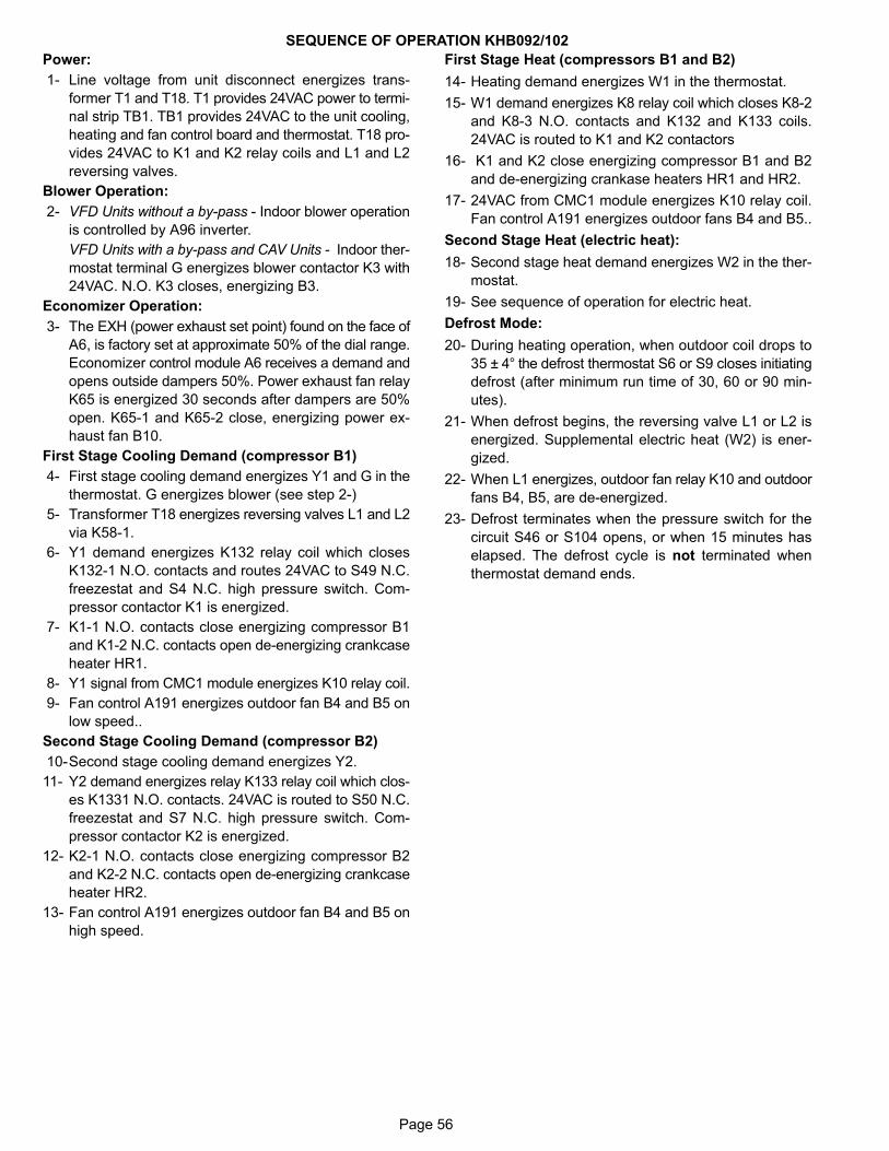
Page 56
SEQUENCE OF OPERATION KHB092/102
Power:
1- Line voltage from unit disconnect energizes trans
former T1 and T18. T1 provides 24VAC power to termi
nal strip TB1. TB1 provides 24VAC to the unit cooling,
heating and fan control board and thermostat. T18 pro
vides 24VAC to K1 and K2 relay coils and L1 and L2
reversing valves.
Blower Operation:
2- VFD Units without a by-pass - Indoor blower operation
is controlled by A96 inverter.
VFD Units with a by-pass and CAV Units - Indoor ther
mostat terminal G energizes blower contactor K3 with
24VAC. N.O. K3 closes, energizing B3.
Economizer Operation:
3- The EXH (power exhaust set point) found on the face of
A6, is factory set at approximate 50% of the dial range.
Economizer control module A6 receives a demand and
opens outside dampers 50%. Power exhaust fan relay
K65 is energized 30 seconds after dampers are 50%
open. K65-1 and K65-2 close, energizing power ex
haust fan B10.
First Stage Cooling Demand (compressor B1)
4- First stage cooling demand energizes Y1 and G in the
thermostat. G energizes blower (see step 2-)
5- Transformer T18 energizes reversing valves L1 and L2
via K58-1.
6- Y1 demand energizes K132 relay coil which closes
K132-1 N.O. contacts and routes 24VAC to S49 N.C.
freezestat and S4 N.C. high pressure switch. Com
pressor contactor K1 is energized.
7- K1-1 N.O. contacts close energizing compressor B1
and K1-2 N.C. contacts open de-energizing crankcase
heater HR1.
8- Y1 signal from CMC1 module energizes K10 relay coil.
9- Fan control A191 energizes outdoor fan B4 and B5 on
low speed..
Second Stage Cooling Demand (compressor B2)
10-Second stage cooling demand energizes Y2.
11- Y2 demand energizes relay K133 relay coil which clos
es K1331 N.O. contacts. 24VAC is routed to S50 N.C.
freezestat and S7 N.C. high pressure switch. Com
pressor contactor K2 is energized.
12- K2-1 N.O. contacts close energizing compressor B2
and K2-2 N.C. contacts open de-energizing crankcase
heater HR2.
13- Fan control A191 energizes outdoor fan B4 and B5 on
high speed.
First Stage Heat (compressors B1 and B2)
14- Heating demand energizes W1 in the thermostat.
15- W1 demand energizes K8 relay coil which closes K8-2
and K8-3 N.O. contacts and K132 and K133 coils.
24VAC is routed to K1 and K2 contactors
16- K1 and K2 close energizing compressor B1 and B2
and de-energizing crankase heaters HR1 and HR2.
17- 24VAC from CMC1 module energizes K10 relay coil.
Fan control A191 energizes outdoor fans B4 and B5..
Second Stage Heat (electric heat):
18- Second stage heat demand energizes W2 in the ther
mostat.
19- See sequence of operation for electric heat.
Defrost Mode:
20- During heating operation, when outdoor coil drops to
35 ± 4° the defrost thermostat S6 or S9 closes initiating
defrost (after minimum run time of 30, 60 or 90 min
utes).
21- When defrost begins, the reversing valve L1 or L2 is
energized. Supplemental electric heat (W2) is ener
gized.
22- When L1 energizes, outdoor fan relay K10 and outdoor
fans B4, B5, are de-energized.
23- Defrost terminates when the pressure switch for the
circuit S46 or S104 opens, or when 15 minutes has
elapsed. The defrost cycle is not terminated when
thermostat demand ends.

Page 57
KHB122 UNIT WIRING SCHEMATIC
5
15
13
17
22`
3
20
21
6
7
8
2
11
16
9
12
1
9
2
6
13
15
17

Page 58
SEQUENCE OF OPERATION KHB122
Power:
1- Line voltage from unit disconnect energizes trans
former T1 and T18. T1 provides 24VAC power to termi
nal strip TB1. TB1 provides 24VAC to the unit cooling,
heating, fan control board and thermostat. T18 pro
vides 24VAC to K1 and K2 relay coils and L1 and L2
reversing valves.
Blower Operation:
2- Indoor thermostat terminal G energizes blower fan
control A191 energizing blower B3.
Economizer Operation:
3- The EXH (power exhaust set point) found on the face of
A6, is factory set at approximate 50% of the dial range.
Economizer control module A6 receives a demand and
opens outside dampers 50%. Power exhaust fan relay
K65 is energized 30 seconds after dampers are 50%
open. K65-1 and K65-2 close, energizing power ex
haust fan B10.
First Stage Cooling Demand (compressor B1)
4- First stage cooling demand energizes Y1 and G in the
thermostat. G energizes blower (see step 2-)
5- Transformer T18 energizes reversing valves L1 and L2
via K58-1.
6- Y1 demand energizes K132 relay coil which closes
K132-1 N.O. contacts and routes 24VAC to S49 N.C.
freezestat and S4 N.C. high pressure switch. Com
pressor contactor K1 is energized.
7- K1-1 N.O. contacts close energizing compressor B1
and K1-2 N.C. contacts open de-energizing crankcase
heater HR1.
8- Y1 signal from CMC1 module energizes K10 relay coil.
9- Fan control A191 energizes outdoor fan B4, B5 and
B21 on low speed..
Second Stage Cooling Demand (compressor B2)
10-Second stage cooling demand energizes Y2.
11- Y2 demand energizes relay K133 relay coil which clos
es K1331 N.O. contacts. 24VAC is routed to S50 N.C.
freezestat and S7 N.C. high pressure switch. Com
pressor contactor K2 is energized.
12- K2-1 N.O. contacts close energizing compressor B2
and K2-2 N.C. contacts open de-energizing crankcase
heater HR2.
13- Fan control A191 energizes outdoor fan B4, B5 and
B21 on high speed.
First Stage Heat (compressors B1 and B2)
14- Heating demand energizes W1 in the thermostat.
15- W1 demand energizes K8 relay coil which closes K8-2
and K8-3 N.O. contacts and K132 and K133 coils.
24VAC is routed to K1 and K2 contactors
16- K1 and K2 close energizing compressor B1 and B2
and de-energizing crankase heaters HR1 and HR2.
17- 24VAC from CMC1 module energizes K10 relay coil.
Fan control A191 energizes outdoor fans B4, B5 and
B21..
Second Stage Heat (electric heat):
18- Second stage heat demand energizes W2 in the ther
mostat.
19- See sequence of operation for electric heat.
Defrost Mode:
20- During heating operation, when outdoor coil drops to
35 ± 4° the defrost thermostat S6 or S9 closes initiating
defrost (after minimum run time of 30, 60 or 90 min
utes).
21- When defrost begins, the reversing valve L1 or L2 is
energized. Supplemental electric heat (W2) is ener
gized.
22- When L1 energizes, outdoor fan relay K10 and outdoor
fans B4, B5 and B21are de-energized.
23- Defrost terminates when the pressure switch for the
circuit S46 or S104 opens, or when 15 minutes has
elapsed. The defrost cycle is not terminated when
thermostat demand ends.

Page 59
ELECTRONIC OR ELECTROMECHANICAL THERMOSTATKHA/KHB SERIES UNITS
POWER:
1- Terminal strip TB1 energizes thermostat components with 24VAC.
OPERATION:
2- TB1 receives data from the electronic thermostat A2 (Y1, Y2, W1, W2, G, OCP). The 24VAC signal from TB1 energizes the appropriate components for heat or cool demand.
Lennox Commercial
ACCESSORIES
REV. 2.0
REMOVEP3 WHEN ECONOMIZERIS USED,ONLY ON KCA,KGA AND KHA 180 THROUGH 300 UNITS.
HEAT 2(W2)
ECONOMIZER
24V POWER
BLOWER(G)
HEAT 1(W1)
COOL 1(Y1)
24V COMMON
COOL 2(Y2)
TOUCHSCREEN THERMOSTAT
DESCRIPTIONKEY COMPONENT
A2 SENSOR, ELECTRONIC THERMOSTAT
A63 SENSOR, CO2
CMC3 CLOCK, TIME
J3 JACK, UNIT ECONOMIZER
K65 RELAY, EXHAUST FAN
P3 PLUG, ECONOMIZER BYPASS
R1 SENSOR, MIXED AIR OR SUPPLY AIR
RT2 SENSOR, REMOTE THERMOSTAT
TB1 TERMINAL STRIP, CLASS II VOLTAGE
k65
A
B
24V POWER
COOL 1 (Y1)
24V COMMON
COOL 2 (Y2)
CONNECTION SCHEME FOR KCA, KGA AND KHA092 THROUGH 150 UNITS WITHOUTECONOMIZER ONLY
1
2
1
1

Page 60
KHA/KHB SERIES ECONOMIZER
SEQUENCE OF OPERATION
POWER:
1- Terminal strip TB1 energizes the economizer components with 24VAC.
OPERATION:
2- Enthalpy sensor A7 and A62 (if differential enthalpy is used) communicates to the economizer control
module A6 when to power the damper motor B7.
3- Economizer control module A6 supplies B7 with 0 - 10 VDC to control the positioning of economizer.
4- The damper actuator provides 2 to 10 VDC position feedback.
1
2
4
3

Page 61
EHO-7.5, 15, 22.5, 30, 45 & 60kW Y VOLTAGEKHA/KHB SERIES UNITS
1
3
4
5
9
6
107
11
5
11

Page 62
EHO-7.5, 15, 22.5, 30, 45 & 60kW G, J VOLTAGEKHA/KHB SERIES UNITS
1
3
5
9
6
11
5
4
10
7
11

Page 63
Sequence of Operation -EHO 7.5, 15, 22.5, 30, 45, 60 kW - Y and G, J, M
NOTE: This sequence of operation is for all Electric
Heat kW ratings Y through J voltages. Each step of op
eration is numbered and can be followed in sequence
on the diagrams. Operation for G, J, and M voltages will
be the same.
HEATING ELEMENTS:
1- Terminal Strip TB3 is energized when the unit discon
nect closes. TB3 supplies line voltage to electric heat
elements HE1 through HE7. Each element is protected
by fuse F3.
SECOND STAGE HEAT:
2- Heating demand initiates at W1 in thermostat.
3- 24VAC W2 signal is routed through from the thermo
stat to TB1. After S15 N.C. primary limit and S20 sec
ondary limit is proved, the electric heat contactor K15 is
energized.
4- N.O. contacts K15-1 close allowing the first bank of ele
ments to be energized.
5- Relay K9 is energized. N.O. contacts K9-1 close ener
gizing timer DL2.
6- After a 30-second delay, DL2 closes energizing con
tactor K16.
7- N.O. contacts K16-1 close allowing the second bank of
elements to be energized.
END OF SECOND STAGE HEAT:
8- Heating demand is satisfied. Terminal W1 in the ther
mostat is de-energized.
9- Electric heat contactor K16 is de-energized.
10- The second set of electric heat elements are de-ener
gized.
11- Electric heat contactor K15 is de-energized.
12- The first set of electric heat elements are de-ener
gized.