Embed Size (px)
Citation preview
8/6/2019 KF01G
http://slidepdf.com/reader/full/kf01g 1/2
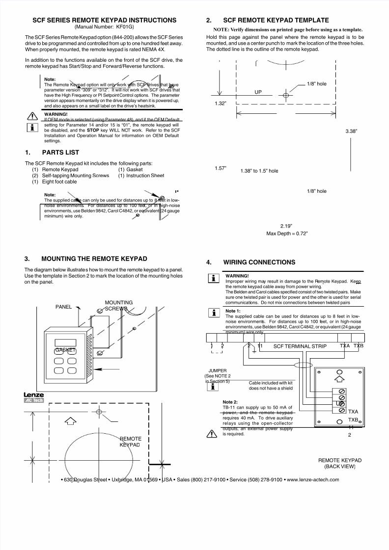
2. SCF REMOTE KEYPAD TEMPLATE
NOTE: Verify dimensions on printed page before using as a template.
Hold this page against the panel where the remote keypad is to bemounted, and use a center punch to mark the location o the three holesThe dotted line is the outline o the remote keypad.
4. WIRING CONNECTIONS
WARNING!
Improper wiring may result in damage to the Remote Keypad. Keepthe remote keypad cable away rom power wiring.The Belden and Carol cables specifed consist o two twisted pairs. Makesure one twisted pair is used or power and the other is used or serialcommunications. Do not mix connections between twisted pairs
Note 1:
The supplied cable can be used or distances up to 8 eet in low-noise environments. For distances up to 100 eet, or in high-noiseenvironments, use Belden 9842, Carol C4842, or equivalent (24 gaugeminimum) wire only.
SCF SERIES REMOTE KEYPAD INSTRUCTIONS(Manual Number: KF01G)
The SCF Series Remote Keypad option (844-200) allows the SCF Seriesdrive to be programmed and controlled rom up to one hundred eet away.When properly mounted, the remote keypad is rated NEMA 4X.
In addition to the unctions available on the ront o the SCF drive, theremote keypad has Start/Stop and Forward/Reverse unctions.
Note:
The Remote Keypad option will only work with SCF drives that haveparameter version “309” or “312”. It will not work with SCF drives that
have the High Frequency or PI Setpoint Control options. The parameterversion appears momentarily on the drive display when it is powered up,and also appears on a small label on the drive’s heatsink.
WARNING!
I OEM mode is selected (using Parameter 48), and i the OEM Deaultsetting or Parameter 14 and/or 15 is “01”, the remote keypad willbe disabled, and the STOP key WILL NOT work. Reer to the SCFInstallation and Operation Manual or inormation on OEM Deaultsettings.
1. PARTS LIST
The SCF Remote Keypad kit includes the ollowing parts:(1) Remote Keypad (1) Gasket(2) Sel-tapping Mounting Screws (1) Instruction Sheet(1) Eight oot cable
Note:
The supplied cable can only be used or distances up to 8 eet in low-noise environments. For distances up to 100 eet, or in high-noiseenvironments, use Belden 9842, Carol C4842, or equivalent (24 gaugeminimum) wire only.
REMOTE KEYPAD(BACK VIEW)
JUMPER(See NOTE 2in Section 5)
TXA
TXB
11
2
UP
TXA TXB1 1122
Cable included with kitdoes not have a shield
SCF TERMINAL STRIP
1/8” hole
1/8” hole
1.57”
1.32”
1.38” to 1.5” hole
3.38”
2.19”
UP
Max Depth = 0.72”
PANEL
REMOTEKEYPAD
GASKET
MOUNTINGSCREWS
3. MOUNTING THE REMOTE KEYPAD
The diagram below illustrates how to mount the remote keypad to a panel.Use the template in Section 2 to mark the location o the mounting holeson the panel.
Note 2:
TB-11 can supply up to 50 mA opower, and the remote keypadrequires 40 mA. To drive auxiliaryrelays using the open-collectoroutputs, an external power supplyis required.
• 630 Douglas Street • Uxbridge, MA 01569 • USA • Sales (800) 217-9100 • Service (508) 278-9100 • www.lenze-actech.com

8/6/2019 KF01G
http://slidepdf.com/reader/full/kf01g 2/2
(KF01G)
Reverse/Forward key: Selects Forward or Reverse direction.The R/F key is only active i Parameter 17 - ROTATION isset to “2” (FORWARD AND REVERSE).
When the R/F key is pressed, the symbol or the oppositedirection will blink on the display. Press the M key withinour seconds to confrm the rotation change.
Below are the display symbols used to indicate direction:
FORWARD REVERSE
6. REMOTE KEYPAD FUNCTIONS
The M key and the s and t keys on the remote keypad unction thesame as the Mode button and the s and t buttons on the drive. Theother remote keypad unctions are described below:
STOP key: Press STOP to Stop the drive. The STOP keyis active whenever the remote keypad is operational, eveni the remote keypad is only used or programming andmonitoring.
RUN key: Press RUN to Start the drive. The RUN key isonly active i the remote keypad is selected as the Start/Stopcontrol source.
5. SETTING UP THE SCF DRIVE
There are three possible control scenarios when using the remotekeypad:
1. The remote keypad is used or Start/Stop control, Forward/Reverseselection, programming, and monitoring.
2. The remote keypad is used or programming and monitoring, butthe drive’s terminal strip is used or Start/Stop control and Forward/ Reverse selection.
3. The remote keypad is used or programming and monitoring, while
Start/Stop control and Forward/Reverse selection can be toggledbetween the remote keypad and the drive’s terminal strip.
In all o the above scenarios, speed is controlled rom the remote keypadunless another speed reerence source is selected.
Note 1:
The STOP key on the remote keypad will work even i the terminal stripis used or Start/Stop control
1. REMOTE KEYPAD TO PROGRAM, MONITOR AND CONTROL
a. Set Parameter 14 (CONTROL) to “02” (REMOTE KEYPAD ONLY).
b. Install a jumper between terminal TB-1 and TB-2 on the drive’sterminal strip.
2. REMOTE KEYPAD TO PROGRAM AND MONITOR, ANDTERMINAL STRIP TO CONTROL.
a. Set Parameter 14 (CONTROL) to “03” (TERMINAL STRIP ORREMOTE KEYPAD).
b. Wire the Start/Stop and Forward/Reverse circuits to the drive’s
terminal strip according to the SCF manual.
3. TOGGLE CONTROL BETWEEN REMOTE KEYPAD AND
TERMINAL STRIP
a. Set Parameter 14 (CONTROL) to “03” (TERMINAL STRIP ORREMOTE KEYPAD).
b. Choose either Terminal 13A or 13C on the drive as the input that witoggle between remote keypad control and terminal strip control.
To use TB-13A, set Parameter 10 (TB-13A FUNCTION SELECT) to“08” (REMOTE KEYPAD).
To use TB-13C, set Parameter 12 (TB-13C FUNCTION SELECT) to“07” (REMOTE KEYPAD).
c. Wire a selector switch or relay contact between TB-13A or TB-13C(whichever was programmed or REMOTE KEYPAD in Step b aboveand TB-2 on the drive’s terminal strip.
d. Wire the Start/Stop and Forward/Reverse circuits to the drive’terminal strip according to the SCF manual.
If a 2-wire Start/Stop circuit is required, use the Alternate 2- Wire
circuit described in Section 11.3 of the SCF manual.
To select the Remote Keypad as the control source, close TB-13A or TB13C (whichever was programmed or REMOTE KEYPAD) to TB-2.
To select the terminal strip as the control source, open TB-13A or TB-13Cwith respect to TB-2.
Note 2:
When the remote keypad is selected or Start/Stop control, terminalTB-1 on the SCF drive must be closed to TB-2 to allow the drive to run.TB-1 is a Stop input and it is always active. I it is open with respect toTB-2, the drive will not run.
7. TROUBLESHOOTING
CONDITION / DISPLAY POSSIBLE CAUSES
Remote Keypad displayis blank.
Parameter 14 - CONTROL is set to “01”(TERMINAL STRIP ONLY). See Section 5.
The Remote Keypad is not wired correctlyto the drive. See Section 4.
Remote Keypad and/ or SCF drive displays“JF”.
“JF” typically indicates a communicationproblem. Check or proper wiring betweenthe remote keypad and the drive. A “JF”ault can also occur due o the ollowing:
- Attempting to start the drive rom theRemote Keypad and TB-1 is not closed toTB-2. See NOTE 2 in Section 5
- Attempting to power the Remote Keypadand an auxiliary relay rom TB-11. SeeNOTE 2 in Section 4.
The RUN key does not
work to start the drive.
To start the drive using the RUN key, the
Remote Keypad must be selected as thecontrol source, and TB-1 must be closed toTB-2 on the drive’s terminal strip.
The R/F key does notwork to change rotationdirection.
To use the R/F key to change rotationdirection, the Remote Keypad must beselected as the control source, Parameter17 - ROTATION must be set to “02”(FORWARD AND REVERSE), and the M key must be pressed with 4 seconds toconfrm the change. See Section 6.
R F
RUN
STOP
WARNING!
I the remote keypad display is totally blank or is displaying a “JF” ault,the STOP key WILL NOT stop the drive. The remote keypad must beoperational in order or the STOP key to be active


