Embed Size (px)
Citation preview
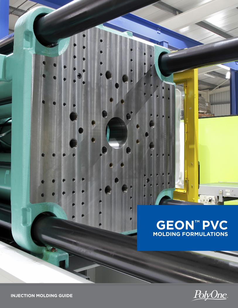
INJECTION MOLDING GUIDE
GEON™ PVC MOLDING FORMULATIONS
CONTENTS
INTRODUCTION 2
INTRODUCTION
Key Considerations for Successful Injection Molding 2
HEALTH AND SAFETY
WARNING: Acetal Not Compatible with Flame Retardant Polymers Like PVC 3
Ventilation 3
Vapors During Processing 3
EQUIPMENT
Injection Molding Machine 4
Barrel 4
Screw 4
Screw Tip 5
End Cap 6
Nozzle 7
PROCESSING
Key Considerations 8
Prior to Molding 11
Starting Equipment Settings 11
Start Up Procedure 13
Process Upsets 14
Shutdown Procedure 15
TROUBLESHOOTING
Troubleshooting Guide 17
2
INTRODUCTION
Polyvinyl chloride (PVC) is the third most produced thermoplastic in the world behind
polypropylene and polyethylene, and hundreds of millions of pounds of rigid PVC are
successfully injection molded around the globe each year. Because PVC is so versatile from
a formulation and processing perspective, it can be injection molded into products for
a variety of markets and applications.
Key Considerations for Successful Injection Molding
Melt Properties—PVC formulations are heat and shear sensitive at processing temperatures.
This means the polymer melt can degrade if it is left at processing temperatures for extended
periods of time or if it experiences high shear when flowing through restricted gates, runners,
or part walls. The melt delivery system, which includes the molding machine injection unit and
the mold runner and gating system, must be streamlined in design to keep material flowing
and avoid stagnant areas or dead spots which can lead to degradation. The melt delivery
system should also be designed to avoid highly restricted flow channels that can generate high
shear. Injection molders who understand and follow these guidelines can successfully mold
rigid PVC into complex shapes in a variety of sizes.
Molding Machine Design and Processing Conditions—Successful production of injection
molded parts starts by converting pellets into a homogeneous, easy flowing melt. This guide
provides recommendations for the appropriate design of molding machine components and
processing conditions to produce an optimal melt for molding high quality rigid PVC parts.
Mold Design—Every polymer has different melt properties. In order to provide the greatest
probability for success, molds should be designed with a specific polymer in mind. Factors
such as metallurgy, gate and runner sizing, wall thickness, and part shrinkage can all change
with polymer type. Contact PolyOne and ask for a Geon™ Performance Materials Technical
Service Representative to obtain more information about designing molds for use with Geon™
Vinyl Rigid Molding formulations.
Material Formulation—While many rigid PVC suppliers have standard flowing compounds for
simple, thick walled shapes like pipe fittings, not all suppliers have high flow formulations for
thin walled complex shaped parts. Geon Vinyl Rigid Molding formulations use state-of-the-art
technology to provide enhanced flow and processing stability to fill a greater variety of larger,
thinner walled, and more complex shapes. Contact PolyOne and ask for a Geon Performance
Materials Technical Service Representative to determine the optimal rigid vinyl formulation
for your part design.
For more information, contact PolyOne:
Phone (Toll Free U.S.): +1.866.765.9663 [+1.866.POLYONE]
Phone (Outside U.S.): +1.440.930.1000
Website: www.polyone.com
3
HEALTH AND SAFETY
As with all injection molded thermoplastics, care must be taken to follow recommendations for
proper equipment and processing conditions to keep workers safe. This section includes health
and safety information regarding injection molding rigid PVC.
WARNING: Acetal Not Compatible with Flame Retardant Polymers Like PVC
It is extremely important that PVC formulations and acetal or acetal copolymers never come
in contact with each other at processing temperatures. At processing temperatures, the small
amount of acidic vapors from PVC can catalyze the rapid depolymerization of acetal to form
formaldehyde gas. The formaldehyde gas, in turn, causes further generation of hydrochloric
acid. An accelerated chemical reaction continues and can ultimately lead to a violent release
of gases.
Acetal and PVC need to be injection molded on different machines isolated from each other.
If this is not possible, then thoroughly purge the molding machine between the two materials
with general purpose ABS, acrylic, or other recommended purging compound and follow with
a thorough mechanical cleaning of the barrel and screw.
Ventilation
It is necessary to have sufficient ventilation in any area where thermoplastics, including PVC,
are injection molded. Sufficient ventilation includes an overhead roof exhaust fan and/or a
sidewall exhaust fan. U.S. Occupational Safety & Health Administration (OSHA) requirements
regarding “adequate” ventilation for molding operations must be followed in the United States
and are recommended for other locations where no specific regulations exist.
Vapors During Processing
All thermoplastics emit vapors or offgasses when processed at melt temperatures. The
identity and concentration of these offgasses around the injection molding machine depends
on variables such as the material formulation, amount processed, processing conditions, and
the effectiveness of the ventilation. Under normal processing conditions with OSHA approved
ventilation, injection molding of PVC does not pose a health risk to workers.
Vinyl resin itself does not have an odor during normal processing. The slight odor emanating
during injection molding of PVC comes from additives incorporated in the PVC formulation
that enhance processing and physical properties.
PVC formulations are heat and shear sensitive at processing temperatures. This means the
polymer melt can degrade if it is left at processing temperatures for extended periods of time
or if it experiences high shear flowing through restricted gates, runners, or part walls. When
rigid PVC overheats, it degrades, yellowing and generating gaseous hydrogen chloride (HCl).
Chlorine gas and vinyl chloride monomer vapor are not generated when PVC degrades. HCl
has a strong unpleasant acrid odor when present at low levels and irritates the nose and throat
at higher levels. If you suspect material is degrading during molding, follow the procedures
outlined in the Processing section under Process Upsets.
4
EQUIPMENT
Injection Molding Machine
Machine Type—Reciprocating screw injection molding machines designed to run engineering
thermoplastics like ABS or PC are usually well suited for processing Geon Vinyl Rigid Molding
formulations. Avoid plunger machines or machines with an extruder combined with a plunger
because they tend to have stagnant areas that lead to material degradation.
Machine Size—An injection molding machine having a minimum clamp force of 2 to 2.5 tons
per square inch (0.0028 to 0.0035 MT/mm2) of projected area is typical. Thinner walls or long
flow lengths may require higher clamp tonnage.
Barrel
Barrel Capacity—A shot weight which uses 50% to 80% of the barrel capacity is recommended
for rigid PVC. A shot weight using 30% to 90% of the barrel capacity may be possible. However
a long cycle time using a low shot weight percentage may lead to degradation of the material
in the barrel. When a barrel’s capacity is rated, it is rated by how many ounces of polystyrene
the specific barrel will hold. Polystyrene has a specific gravity of 1.0 while rigid PVC typically
has a specific gravity of 1.3 to 1.4. This means a barrel rated at 80 ounces of polystyrene will
actually hold about 105 ounces of PVC.
Barrel Metallurgy—Ideally, the injection barrel is bimetallic, meaning there are two layers of
different metals. The inner layer facing the melt is chemical and wear-resistant while the outer
layer is a stronger steel sleeve. Single layer barrels that are only nitrided do not provide the best
chemical resistance, but are commonly used when molding PVC and can work well if properly
maintained. Barrel metals high in iron or cobalt are unacceptable for molding PVC because they
cause pinking or streaking in the end product. Segmented or vented barrels are not acceptable
for molding PVC because both types have stagnant areas impeding material flow (also called
dead spots), which can lead to degradation and ultimately black specs in the finished part. An
example of a very good recommended barrel would be a bimetallic barrel made from a nickel
base alloy with high chromium content for good corrosion resistance against hydrochloric and
other mild acid gasses. The barrel metal should also be compatible with nickel-based materials
used to harden feed screw flights such as Colmonoy® 56.1 Most screw and barrel manufacturers
can supply recommendations for appropriate screw and barrel material combinations.
Screw
Screw Design—Compression ratio is defined as the depth of the first feed flight divided by the
depth of the last metering flight. The recommended compression ratio for a rigid PVC molding
screw is 2.2:1. While screws with compression ratios between 2.0:1 and 3.0:1 have been used
successfully, it is recommended the compression ratio of the screw should be closer to 2.2:1.
As the compression ratio of the screw increases, the processing window for PVC may decrease.
This is especially true when the compression ratio exceeds 2.8:1. A compression ratio less than
2.2:1 will tend not to squeeze all the air out of the melt, causing bubbles to be included in
the shot.
1 Colmonoy® is a registered trademark of Wall Colmonoy Corporation.
5
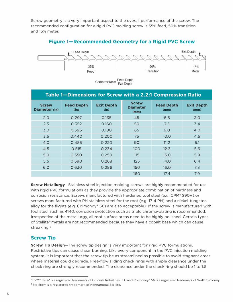
Screw geometry is a very important aspect to the overall performance of the screw. The
recommended configuration for a rigid PVC molding screw is 35% feed, 50% transition
and 15% meter.
Figure 1—Recommended Geometry for a Rigid PVC Screw
Table 1—Dimensions for Screw with a 2.2:1 Compression Ratio
Screw Diameter (in)
Feed Depth (in)
Exit Depth (in)
Screw Diameter
(mm)
Feed Depth (mm)
Exit Depth (mm)
2.0 0.297 0.135 45 6.6 3.0
2.5 0.352 0.160 50 7.5 3.4
3.0 0.396 0.180 65 9.0 4.0
3.5 0.440 0.200 75 10.0 4.5
4.0 0.485 0.220 90 11.2 5.1
4.5 0.515 0.234 100 12.3 5.6
5.0 0.550 0.250 115 13.0 5.9
5.5 0.590 0.268 125 14.0 6.4
6.0 0.630 0.286 150 16.0 7.3
160 17.4 7.9
Screw Metallurgy—Stainless steel injection molding screws are highly recommended for use
with rigid PVC formulations as they provide the appropriate combination of hardness and
corrosion resistance. Screws manufactured with hardened tool steel (e.g. CPM® S90V) or
screws manufactured with PH stainless steel for the root (e.g. 17-4 PH) and a nickel-tungsten
alloy for the flights (e.g. Colmonoy® 56) are also acceptable.2 If the screw is manufactured with
tool steel such as 4140, corrosion protection such as triple chrome-plating is recommended.
Irrespective of the metallurgy, all root surface areas need to be highly polished. Certain types
of Stellite® metals are not recommended because they have a cobalt base which can cause
streaking.3
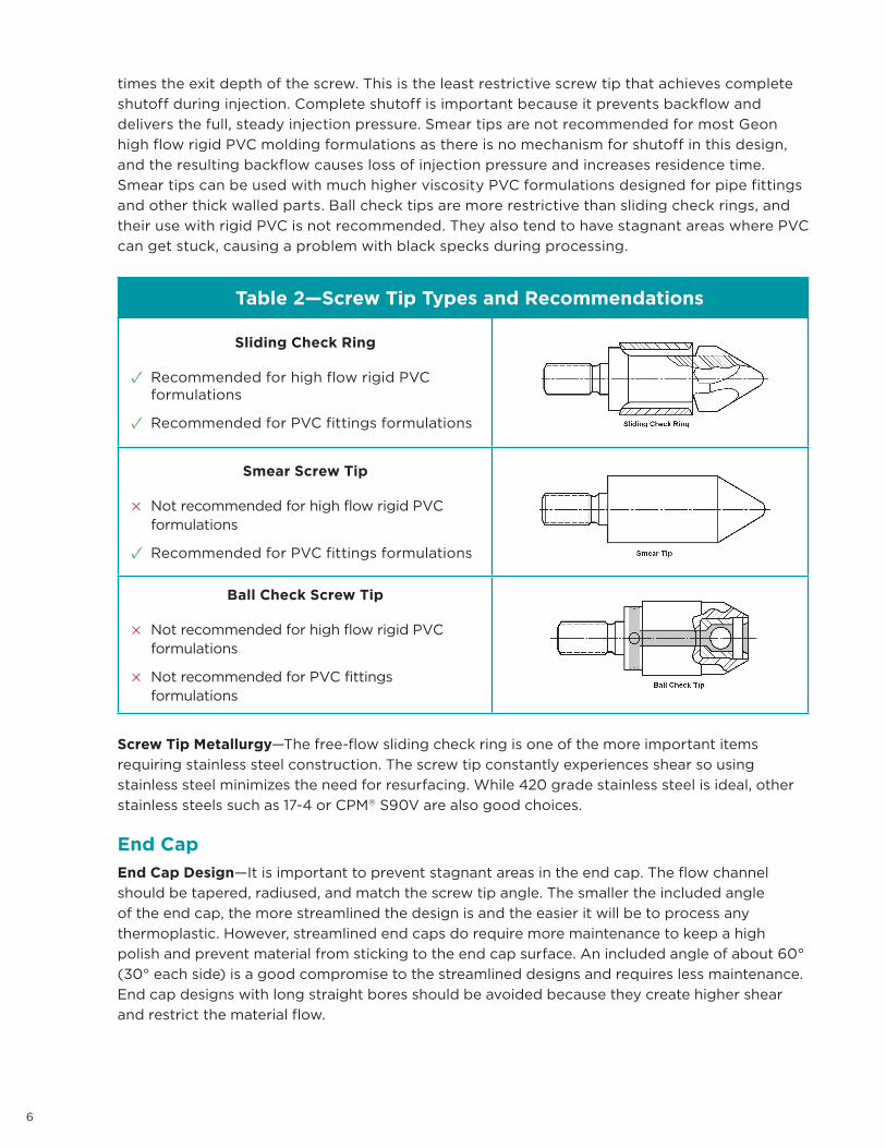
Screw Tip
Screw Tip Design—The screw tip design is very important for rigid PVC formulations.
Restrictive tips can cause shear burning. Like every component in the PVC injection molding
system, it is important that the screw tip be as streamlined as possible to avoid stagnant areas
where material could degrade. Free-flow sliding check rings with ample clearance under the
check ring are strongly recommended. The clearance under the check ring should be 1 to 1.5
2 CPM® S90V is a registered trademark of Crucible Industries LLC and Colmonoy® 56 is a registered trademark of Wall Colmonoy.3 Stellite® is a registered trademark of Kennametal Stellite.
6
times the exit depth of the screw. This is the least restrictive screw tip that achieves complete
shutoff during injection. Complete shutoff is important because it prevents backflow and
delivers the full, steady injection pressure. Smear tips are not recommended for most Geon
high flow rigid PVC molding formulations as there is no mechanism for shutoff in this design,
and the resulting backflow causes loss of injection pressure and increases residence time.
Smear tips can be used with much higher viscosity PVC formulations designed for pipe fittings
and other thick walled parts. Ball check tips are more restrictive than sliding check rings, and
their use with rigid PVC is not recommended. They also tend to have stagnant areas where PVC
can get stuck, causing a problem with black specks during processing.
Table 2—Screw Tip Types and Recommendations
Sliding Check Ring
✓ Recommended for high flow rigid PVC formulations
✓ Recommended for PVC fittings formulations
Smear Screw Tip
× Not recommended for high flow rigid PVC formulations
✓ Recommended for PVC fittings formulations
Ball Check Screw Tip
× Not recommended for high flow rigid PVC formulations
× Not recommended for PVC fittings formulations
Screw Tip Metallurgy—The free-flow sliding check ring is one of the more important items
requiring stainless steel construction. The screw tip constantly experiences shear so using
stainless steel minimizes the need for resurfacing. While 420 grade stainless steel is ideal, other
stainless steels such as 17-4 or CPM® S90V are also good choices.
End Cap
End Cap Design—It is important to prevent stagnant areas in the end cap. The flow channel
should be tapered, radiused, and match the screw tip angle. The smaller the included angle
of the end cap, the more streamlined the design is and the easier it will be to process any
thermoplastic. However, streamlined end caps do require more maintenance to keep a high
polish and prevent material from sticking to the end cap surface. An included angle of about 60°
(30° each side) is a good compromise to the streamlined designs and requires less maintenance.
End cap designs with long straight bores should be avoided because they create higher shear
and restrict the material flow.
7
End Cap Metallurgy—The end cap should be made out of stainless steel, such as 420SS or 17-4.
If it is not feasible to purchase a stainless steel end cap, triple chrome-plating should be used to
protect the base steel.
Nozzle
Nozzle Design—A nozzle length of 1 to 6 inches (2.5 to 15.2 cm) is suggested. Longer nozzle
lengths may lead to shear burning. The minimum recommended exit diameter of the nozzle is
0.25 inch (0.64 cm)—for a 6 to 8 oz shot. As the shot size is increased, the nozzle exit diameter
should also be increased. Nozzles with a full internal taper are preferred, although straight-bore
nozzles are acceptable with shorter lengths. The nozzle tip diameter should be up to 0.04 in
(1 mm) smaller than the rear opening diameter of the mold sprue bushing so that a complete
seal is formed and no flash occurs.
Nozzle Metallurgy—Longer and more restrictive nozzles are more likely to result in shear
burning. Because degradation accompanies shear burning, constructing the nozzles with
stainless steel is an important preventative measure. For molders who do not injection
mold PVC often or have short, non-restrictive nozzles, stainless steel may not be a feasible
investment. In such cases, standard tool steel such as 4140 is acceptable. Nozzles made of
4140 must have their internal bores polished and well maintained.
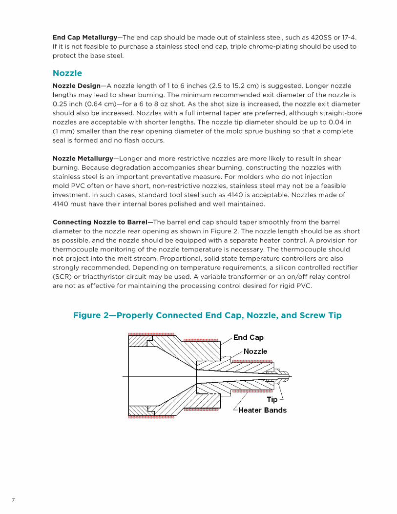
Connecting Nozzle to Barrel—The barrel end cap should taper smoothly from the barrel
diameter to the nozzle rear opening as shown in Figure 2. The nozzle length should be as short
as possible, and the nozzle should be equipped with a separate heater control. A provision for
thermocouple monitoring of the nozzle temperature is necessary. The thermocouple should
not project into the melt stream. Proportional, solid state temperature controllers are also
strongly recommended. Depending on temperature requirements, a silicon controlled rectifier
(SCR) or triacthyristor circuit may be used. A variable transformer or an on/off relay control
are not as effective for maintaining the processing control desired for rigid PVC.
Figure 2—Properly Connected End Cap, Nozzle, and Screw Tip
PROCESSING
8
PROCESSING
Key Considerations
Developing Optimal Properties—To develop optimal physical properties and appearance
of a rigid PVC formulation, the material should be processed at the maximum feasible melt
temperature without degrading. It should be injected at a moderate speed, packed at the
minimum pressure required to fill out the mold details, and allowed to relax sufficiently during
the cooling stage.
Regrind—Runners, trim, short shots and other sources of clean PVC can be reground and
mixed with virgin material. A regrind range of 10% to 25% is recommended, although higher
regrind percentages up to 100% are being used in non-UL applications. It is important to
maintain sharp grinding blades. Grinding generates significant heat so reground PVC should
be cooled to below 150°F (66°C) before storing to prevent degradation of the material.
Melt Temperature—The ideal melt temperature range for Geon Vinyl Rigid Molding
formulations is 390°F to 405°F (199°C to 207°C). The best way to determine melt temperature
is to pull the injection unit away from the mold and take an “air shot”. Measure the temperature
of the melt with a calibrated needle probe pyrometer. In addition, the melt should look smooth
and glossy. A dull melt indicates too low a melt temperature and a rough surface indicates
either a high melt temperature or moisture in the melt.
Neutralize the Mold—Using neutralizer spray on the mold cavity surfaces is inexpensive and
the best defense against tool corrosion. For best overall tool life, neutralize the mold cavity
surfaces once per 24-hour day. Any tool, regardless of metallurgy, must be neutralized at least
once a week. To properly apply neutralizer, spray all mold surfaces and runner blocks, with
particular attention to the sprue bushing and other hard to reach spots.
The neutralizer spray must have a low moisture content to effectively work with PVC. It is also
important that the neutralizer be strong enough to effectively neutralize hydrochloric acid residue
left after molding PVC. Neutralizer also acts to protect the mold from corrosion caused by
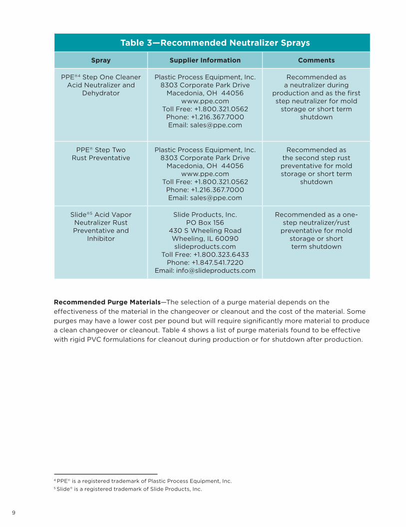
fingerprint acids and other damaging chemicals from the injection molding environment. Table 3
lists recommended neutralizer sprays and their suggested use.
9
Table 3—Recommended Neutralizer Sprays
Spray Supplier Information Comments
PPE®4 Step One CleanerAcid Neutralizer and
Dehydrator
Plastic Process Equipment, Inc.8303 Corporate Park Drive
Macedonia, OH 44056www.ppe.com
Toll Free: +1.800.321.0562Phone: +1.216.367.7000Email: [email protected]
Recommended as a neutralizer during
production and as the first step neutralizer for mold
storage or short term shutdown
PPE® Step TwoRust Preventative
Plastic Process Equipment, Inc.8303 Corporate Park Drive
Macedonia, OH 44056www.ppe.com
Toll Free: +1.800.321.0562Phone: +1.216.367.7000Email: [email protected]
Recommended as the second step rust preventative for mold storage or short term
shutdown
Slide®5 Acid Vapor Neutralizer Rust Preventative and
Inhibitor
Slide Products, Inc.PO Box 156
430 S Wheeling RoadWheeling, IL 60090slideproducts.com
Toll Free: +1.800.323.6433Phone: +1.847.541.7220
Email: [email protected]
Recommended as a one-step neutralizer/rust
preventative for mold storage or short term shutdown
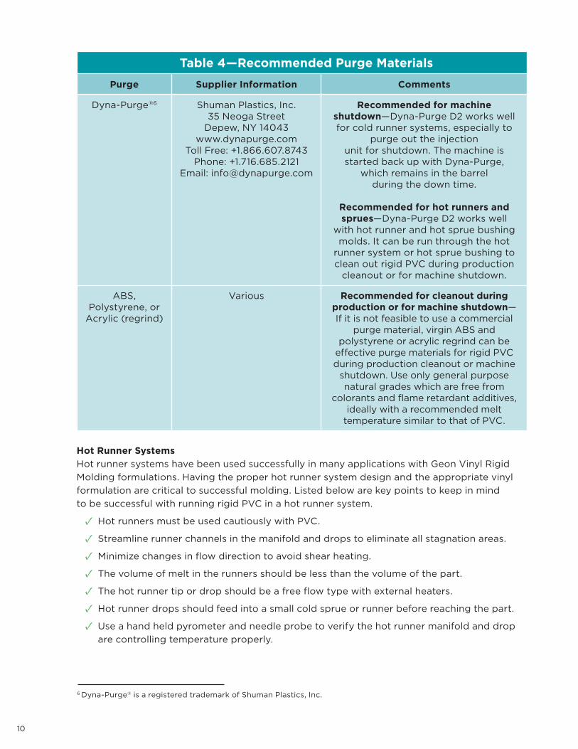
Recommended Purge Materials—The selection of a purge material depends on the
effectiveness of the material in the changeover or cleanout and the cost of the material. Some
purges may have a lower cost per pound but will require significantly more material to produce
a clean changeover or cleanout. Table 4 shows a list of purge materials found to be effective
with rigid PVC formulations for cleanout during production or for shutdown after production.
4 PPE® is a registered trademark of Plastic Process Equipment, Inc.5 Slide® is a registered trademark of Slide Products, Inc.
10
Table 4—Recommended Purge Materials
Purge Supplier Information Comments
Dyna-Purge®6 Shuman Plastics, Inc.35 Neoga Street
Depew, NY 14043www.dynapurge.com
Toll Free: +1.866.607.8743Phone: +1.716.685.2121
Email: [email protected]
Recommended for machine shutdown—Dyna-Purge D2 works well for cold runner systems, especially to
purge out the injection unit for shutdown. The machine is started back up with Dyna-Purge,
which remains in the barrelduring the down time.
Recommended for hot runners and sprues—Dyna-Purge D2 works well
with hot runner and hot sprue bushing molds. It can be run through the hot
runner system or hot sprue bushing to clean out rigid PVC during production
cleanout or for machine shutdown.
ABS, Polystyrene, or
Acrylic (regrind)
Various Recommended for cleanout during production or for machine shutdown—If it is not feasible to use a commercial
purge material, virgin ABS and polystyrene or acrylic regrind can be
effective purge materials for rigid PVC during production cleanout or machine
shutdown. Use only general purpose natural grades which are free from
colorants and flame retardant additives, ideally with a recommended melt
temperature similar to that of PVC.
Hot Runner Systems
Hot runner systems have been used successfully in many applications with Geon Vinyl Rigid
Molding formulations. Having the proper hot runner system design and the appropriate vinyl
formulation are critical to successful molding. Listed below are key points to keep in mind
to be successful with running rigid PVC in a hot runner system.
✓ Hot runners must be used cautiously with PVC.
✓ Streamline runner channels in the manifold and drops to eliminate all stagnation areas.
✓ Minimize changes in flow direction to avoid shear heating.
✓ The volume of melt in the runners should be less than the volume of the part.
✓ The hot runner tip or drop should be a free flow type with external heaters.
✓ Hot runner drops should feed into a small cold sprue or runner before reaching the part.
✓ Use a hand held pyrometer and needle probe to verify the hot runner manifold and drop
are controlling temperature properly.
6 Dyna-Purge® is a registered trademark of Shuman Plastics, Inc.
11
✓ PVC must be purged from the hot runner system in the event of intermittent delays or process
shutdowns.
✓ Purging with Dyna-Purge D2 works best for PVC hot runner systems.
✓ The injection molding press should have an ability to purge through the hot runner system
with the mold in the open position.
Prior to Molding
Prepare the Mold
✓ Clean both mold halves thoroughly using a good recommended cleaner.
✓ Make sure all vents are thoroughly cleaned and free of any pre-applied rust preventative,
dirt or other material build-up.
✓ Address all water leaks and check for adequate water flow through the tooling.
✓ Clean and polish sprue bushing. Check for rough spots.
✓ Check nozzle and sprue orifice for proper match and size.
✓ Review your process set up sheet for proper mold temperature settings. If none exists,
refer to this manual or contact PolyOne and ask for Geon Performance Materials Technical
Service.
Prepare the Molding Machine
✓ Set barrel temperature controllers to desired or recommended temperatures.
✓ Reduce injection pressures, back pressures, and screw RPM to the lower end of their
operating ranges.
Prepare the Material
Drying—Drying is not usually necessary for rigid PVC. However, surface moisture can form on
the pellet, especially in hot, humid summer months or in tropical locations. To reduce the need
for drying, store material covered in a cool dry location. When drying is necessary, it should be
done at 120°F–150°F (49°C–66°C) for approximately two hours.
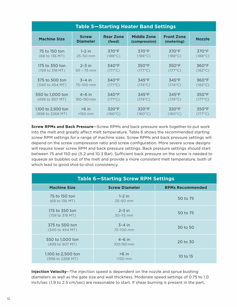
Starting Equipment Settings
Heater Band Temperatures—Table 5 represents typical starting heater ban settings for
molding rigid PVC. On most molding machines designed for engineering thermoplastics, these
starting parameters will result in a melt temperature close to the recommended range of 390°F
to 405°F (199°C to 207°C). The melt temperature should be measured by taking an air shot
and measuring the temperature of the melt with a needle probe pyrometer. In addition, the
melt should look smooth and glossy. A dull looking melt indicates a low melt temperature while
a rough surface melt indicates a melt that is too hot and/or contains moisture.
The heater band settings in Table 5 represent an ascending temperature profile which is most
commonly used. Sometimes a reverse or descending temperature profile is useful. It melts
the pellets soon after they are fed to the screw, resulting in reduced abrasion, more efficient
pumping of the melt forward, and reduced pinking or black streaks.
12
Table 5—Starting Heater Band Settings
Machine SizeScrew
DiameterRear Zone
(feed)Middle Zone (compression)
Front Zone (metering)
Nozzle
75 to 150 ton(68 to 136 MT)
1–2 in25–50 mm
370°F (188°C)
370°F (188°C)
370°F (188°C)
370°F (188°C)
175 to 350 ton(159 to 318 MT)
2–3 in50 – 75 mm
340°F (171°C)
350°F (177°C)
350°F (177°C)
360°F (182°C)
375 to 500 ton(340 to 454 MT)
3–4 in75–100 mm
340°F (171°C)
345°F (174°C)
345°F (174°C)
360°F (182°C)
550 to 1,000 ton(499 to 907 MT)
4–6 in100–150 mm
340°F (171°C)
345°F (174°C)
345°F (174°C)
350°F (177°C)
1,100 to 2,500 ton(998 to 2268 MT)
>6 in>150 mm
320°F (160°C)
320°F (160°C)
320°F (160°C)
350°F (177°C)
Screw RPMs and Back Pressure—Screw RPMs and back pressure work together to put work
into the melt and greatly affect melt temperature. Table 6 shows the recommended starting
screw RPM settings for a range of machine sizes. Screw RPMs and back pressure settings will
depend on the screw compression ratio and screw configuration. More severe screw designs
will require lower screw RPM and back pressure settings. Back pressure settings should start
between 75 and 150 psi (5.2 and 10.3 Bar). Sufficient back pressure on the screw is needed to
squeeze air bubbles out of the melt and provide a more consistent melt temperature, both of
which lead to good shot-to-shot consistency.
Table 6—Starting Screw RPM Settings
Machine Size Screw Diameter RPMs Recommended
75 to 150 ton(68 to 136 MT)
1–2 in25–50 mm
50 to 75
175 to 350 ton(159 to 318 MT)
2–3 in50–75 mm
50 to 75
375 to 500 ton(340 to 454 MT)
3–4 in75–100 mm
30 to 50
550 to 1,000 ton(499 to 907 MT)
4–6 in100–150 mm
20 to 30
1,100 to 2,500 ton(998 to 2268 MT)
>6 in>150 mm
10 to 15
Injection Velocity—The injection speed is dependent on the nozzle and sprue bushing
diameters as well as the gate size and wall thickness. Moderate speed settings of 0.75 to 1.0
inch/sec (1.9 to 2.5 cm/sec) are reasonable to start. If shear burning is present in the part,
13
reduce the injection speed. If no shear burning is present in the part and the part is not
completely filled, increase the injection speed until shear burning is observed and then reduce
injection speed in small increments until no shear burning is present. On molding machines
with variable injection speed, it is sometimes helpful to use lower injection speeds until the
material has filled the runner, gates, and initial regions of the part.
Injection and Holding Pressures—The amount of first stage injection pressure (booster
pressure) that is required to fill the mold cavity will depend on the melt temperature, injection
speed, mold temperature and mold design. Generally, pressures in the range of 50% to 70%
of the maximum available offer the best consistency and processing latitude. It is advisable
to start with lower pressures and increase to the desired pressure to avoid flashing the mold.
The timer for the first stage injection pressure should be set to switch to holding pressure just
as the part is completely filled. This should coincide with the moment the screw completes
its relatively fast forward travel leaving a 0.125 to 0.25 inch (0.32 to 0.64 cm) cushion. The
second stage injection pressure (holding pressure) should be just enough to maintain a full
part as the part cools and shrinks in the cavity. Holding pressure is typically 1/2 to 2/3 of the first
stage injection pressure. Parts having thicker cross sections usually require greater holding
pressure. Over-packing the part with excessive holding pressure or time on the second stage
injection pressure increases molded-in stress that can be detrimental to physical properties.
Generally, sink marks away from the gate indicate that more injection pressure or time is
needed while sink marks near the gate indicate that more hold pressure or time is needed.
Once it is apparent that gates are frozen off, hold pressure should be reduced to save on
energy consumption. A small cushion of material must be maintained ahead of the screw to
compensate for part shrinkage as it cools under holding pressure, thus preventing sink marks.
Mold Temperature—Accurate mold temperature control is essential for optimizing cycle time
and finished part quality. Rigid PVC formulations are usually run with mold heater-coolers
between 40-120°F (4°C-49°C). Higher mold temperatures usually give improved surface
appearance, better material flow, improved weld line integrity and lower part stress. Cooler
mold temperatures give shorter cycle times. High pumping rates of the temperature control
medium with minimal line and coupler restrictions will improve temperature control in the tool
and optimize the combination of part quality and cycle time. Running the “B” half of the mold
cooler than the “A” half usually facilitates easier part ejection and removal.
Start Up Procedure
1. IMPORTANT DETAIL: Purge the barrel with natural general purpose ABS, styrene,
acrylic (regrind), or approved purge material (see Recommended Purge Materials) prior
to introducing PVC to the injection unit. Use of polyethylene or polypropylene is not
recommended because they are immiscible with PVC and will result in delamination
of finished parts.
2. Injection and back pressures should be checked and set during purging or after start of
molding cycle.
3. After barrel temperature settings have stabilized, introduce the PVC into the machine.
4. Take air shot melt temperatures and check using a hand held pyrometer and needle probe.
If melt temperature is in the range of 380°F to 395°F (193°C to 202°C), proceed. If not,
adjust heater band settings, screw RPM or back pressure to reach proper melt temperature.
Recheck melt temperature after machine stabilizes in a production mode and maintain
390°F to 405°F (199°C to 207°C) melt.
14
5. Observe molten PVC appearance during the air shots. A smooth glossy surface is indicative
of a good homogenous melt temperature. A smoking or frothy melt suggests melt
temperature may be too high. Porous or steaming melt may indicate moisture.
6. Lightly, spray mold release into the core, cavity and sprue bushing, and commence
molding PVC into the mold.
7. Start molding parts in the semi-automatic operation mode.
8. Check and adjust injection pressures. Use medium range to start.
9. Check and adjust injection velocities. Slow to moderate to start. Adjust up or down as
needed.
10. Adjust pressures and times to make acceptable parts.
11. Adjust screw RPM and back pressure to obtain optimum melt temperature.
12. Check heater zones for override and correct settings.
13. Mold temperatures should be checked with a hand pyrometer and surface probe.
14. If a sprue should hang up in the sprue bushing, never try to shoot through the hung up
sprue to remove it. This may cause extensive shear heating leading to degradation of
the PVC.
Process Upsets
Expected Cycle Interruptions—Rigid PVC is susceptible to thermal degradation upon
prolonged exposure to processing temperatures without moving through the barrel, runners,
etc. Therefore, if an interruption in the molding cycle is expected to last longer than 15 minutes,
the injection unit should be pulled back from the mold and the rigid PVC should be processed
through the barrel by making occasional air shots. If the delay is lengthy, the PVC should be
completely purged from the barrel with natural general purpose ABS, styrene, acrylic (regrind),
or recommended purge material (see Recommended Purge Materials).
Unexpected Cycle Interruptions—In the event a power failure occurs during the molding
operation and the PVC cools and solidifies in the barrel, the following procedures should be
used.
1. Shut off heaters to barrel and nozzle.
2. Cool barrel with fans if emergency power is available.
3. Restart injection molding press when power is restored.
4. Set barrel and nozzle heater band temperatures to 250°F (121°C) for one hour.
5. Increase barrel and nozzle heater band temperatures 25°F (14°C) every 30 minutes until
reaching 350°F (177°C).
6. When the barrel heater band temperatures approach 350°F (177°C), start jogging the
screw until full rotation starts and then purge barrel with purge material.
Once the barrel is fully purged, the rigid PVC being used can be reintroduced into the barrel
and production resumed.
15
Degradation During Molding—If you experience slight degradation of PVC from the barrel
during molding (color shift and odor change), use the following procedure to eliminate the
degradation.
1. Continue PVC molding operation.
2. Recheck all nozzle and barrel temperatures controllers to make sure they are within
recommended guidelines and operating properly.
3. Recheck screw RPM and injection speed to make sure they are within recommended
guidelines and operating properly.
4. Resolve these or other issues that can lead to higher than recommended melt temperatures
or long residence times.
5. Resume normal operations.
If you experience severe degradation of PVC from the barrel during molding (significantly
discolored material and strong, pungent odor of HCl), use the following procedure to eliminate
the degradation.
1. Protect eyes, nose, and throat from hot release of vapors from degraded material. Wear
a National Institute for Occupational Safety and Health (NIOSH) approved air-purifying,
full-facepiece respirator with a chin-style, front- or back-mounted canister providing
protection against the compound of concern.
2. Retract the injection unit from the mold.
3. Evacuate the air around the injection molding machine.
4. Remove rigid PVC from hopper.
5. Put purge material such as general purpose ABS, PS, or acrylic into hopper.
6. Completely purge barrel of PVC as rapidly as possible into small portions of melt
(less than 1.5 lb/0.7 kg).
7. Place degraded melt into bucket of water and eliminate employee exposure.
8. Resolve issues with errant heater zone settings, defective controllers, or other issue that
can lead to higher than recommended melt temperatures or long residence times.
9. Purge barrel with a small amount of rigid PVC to make sure machine is operating properly.
10. Consult site Environmental Health & Safety function prior to resuming normal operations.
Shutdown Procedure
When the molding of PVC has been completed, the injection molding machine should not
be shut down with rigid PVC in the barrel because it is susceptible to thermal degradation
upon prolonged exposure to processing temperatures without moving through the barrel.
The injection unit should be pulled back from the mold and the PVC must be purged from the
barrel with natural general purpose ABS, styrene, acrylic (regrind), or recommended purge
material (see Recommended Purge Materials). Polyethylene or polypropylene are immiscible
with PVC and should not be used as a purge material. Flame retardant materials should not
be used since they also are susceptible to degradation.
16
If rigid PVC is accidentally overheated in the barrel, both the screw and barrel may have to be
cleaned. If the condition is not severe, this may be accomplished by purging the barrel with
natural general purpose ABS, polystyrene, acrylic (regrind), or recommended purge material
(see Recommended Purge Materials) at the current temperature. If this method does not work,
remove the screw from the barrel and clean mechanically.
1. Maintain production settings for barrel and nozzle heater bands, screw RPM, and injection
velocity.
2. Retract injection unit away from mold, leaving ample room for purge to exit nozzle.
3. Empty and thoroughly clean the hopper of any PVC.
4. Empty the barrel of PVC by bringing the screw completely forward and running the
extruder in the forward position until barrel is empty. Use high back pressure to maintain
forward position. Approximately 500 psi (34 Bar) of back pressure will be needed
depending on equipment type.
5. Feed purge material into the barrel and run extruder until PVC is flushed from the barrel.
6. Lower back pressure and manually make air shots at 25% of injection capacity to ensure
barrel is clean and free of PVC.
7. Empty the barrel of purge material by bringing the screw completely forward and running
the extruder in the forward position until barrel is empty.
8. The molding machine can now be safely shut down or used to mold another polymer
except acetal. (If acetal will processed in the same machine as PVC, the injection unit must
be disassembled and completely cleaned mechanically).
17
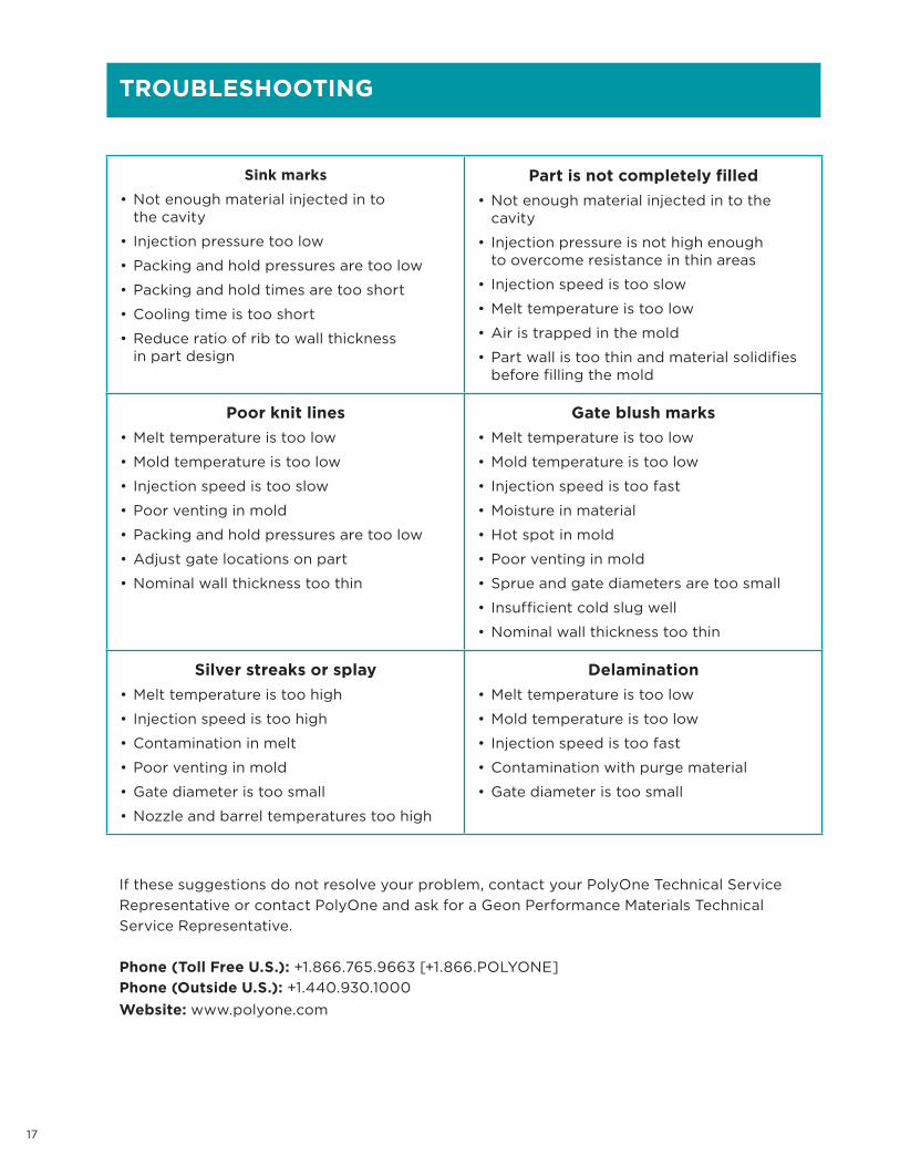
TROUBLESHOOTING
Sink marks
• Not enough material injected in to the cavity
• Injection pressure too low
• Packing and hold pressures are too low
• Packing and hold times are too short
• Cooling time is too short
• Reduce ratio of rib to wall thickness in part design
Part is not completely filled
• Not enough material injected in to the cavity
• Injection pressure is not high enough to overcome resistance in thin areas
• Injection speed is too slow
• Melt temperature is too low
• Air is trapped in the mold
• Part wall is too thin and material solidifies before filling the mold
Poor knit lines
• Melt temperature is too low
• Mold temperature is too low
• Injection speed is too slow
• Poor venting in mold
• Packing and hold pressures are too low
• Adjust gate locations on part
• Nominal wall thickness too thin
Gate blush marks
• Melt temperature is too low
• Mold temperature is too low
• Injection speed is too fast
• Moisture in material
• Hot spot in mold
• Poor venting in mold
• Sprue and gate diameters are too small
• Insufficient cold slug well
• Nominal wall thickness too thin
Silver streaks or splay
• Melt temperature is too high
• Injection speed is too high
• Contamination in melt
• Poor venting in mold
• Gate diameter is too small
• Nozzle and barrel temperatures too high
Delamination
• Melt temperature is too low
• Mold temperature is too low
• Injection speed is too fast
• Contamination with purge material
• Gate diameter is too small
If these suggestions do not resolve your problem, contact your PolyOne Technical Service
Representative or contact PolyOne and ask for a Geon Performance Materials Technical
Service Representative.
Phone (Toll Free U.S.): +1.866.765.9663 [+1.866.POLYONE]
Phone (Outside U.S.): +1.440.930.1000
Website: www.polyone.com

1.866.POLYONE
www.polyone.com
Copyright © 2018, PolyOne Corporation. PolyOne makes no representations, guarantees, or warranties of any kind with respect to the information contained in this document about its
accuracy, suitability for particular applications, or the results obtained or obtainable using the information. Some of the information arises from laboratory work with small-scale equipment
which may not provide a reliable indication of performance or properties obtained or obtainable on larger-scale equipment. Values reported as “typical” or stated without a range do not
state minimum or maximum properties; consult your sales representative for property ranges and min/max specifications. Processing conditions can cause material properties to shift
from the values stated in the information. PolyOne makes no warranties or guarantees respecting suitability of either PolyOne’s products or the information for your process or end-use
application. You have the responsibility to conduct full-scale end-product performance testing to determine suitability in your application, and you assume all risk and liability arising from
your use of the information and/or use or handling of any product. POLYONE MAKES NO WARRANTIES, EXPRESS OR IMPLIED, INCLUDING, BUT NOT LIMITED TO, IMPLIED WARRANTIES
OF MERCHANTABILITY AND FITNESS FOR A PARTICULAR PURPOSE, either with respect to the information or products reflected by the information. This literature shall NOT operate as
permission, recommendation, or inducement to practice any patented invention without permission of the patent owner.