Embed Size (px)
Citation preview
Hydrogen Fuel Cell and KERS Technologies For Powering Urban Bus
With Zero Emission Energy Cycle
National Scientific Seminar SIDT
POLITECNICO DI TORINO 14-15.09.2015
University of L’Aquila ITALY
D’Ovidio G., Masciovecchio C., Rotondale A.
1
Overview
Introduction
System project and objectives
Vehicle overview and technologies
Energy balance in solar-hydrogen cycle
Conclusions
2
Fuel consumption per bus
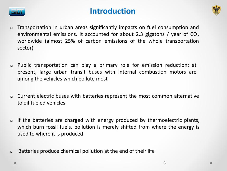
Transportation in urban areas significantly impacts on fuel consumption and environmental emissions. It accounted for about 2.3 gigatons / year of CO2 worldwide (almost 25% of carbon emissions of the whole transportation sector)
Introduction
Current electric buses with batteries represent the most common alternative to oil-fueled vehicles
If the batteries are charged with energy produced by thermoelectric plants, which burn fossil fuels, pollution is merely shifted from where the energy is used to where it is produced
Public transportation can play a primary role for emission reduction: at present, large urban transit buses with internal combustion motors are among the vehicles which pollute most
Batteries produce chemical pollution at the end of their life
3
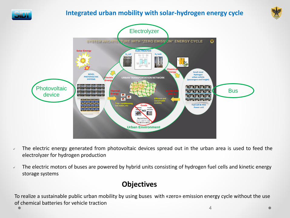
The electric energy generated from photovoltaic devices spread out in the urban area is used to feed the electrolyzer for hydrogen production
Integrated urban mobility with solar-hydrogen energy cycle
Accumulatore elettromeccanico
Cicli infiniti
Big sized buses
Batteries
disposal
Traffic
emission
Electric
Energy
Chemical
Energy
Solar Energy
Thermal
Energy
Tele- conditioning, hot water, etc
Efficient and sustainable
mobility
ELECTROLYSISH2 tankH2 cell
NOVEL PHOTOVOLTAIC
SYSTEMS
Mechanical
Energy
Small sizedHydrogen
urban vehicle(passengers and freight)
FESS
Urban Environment
NO
URBAN TRANSPORTATION NETWORK
Goals Fuel cell & FESSPower unit
To realize a sustainable public urban mobility by using buses with «zero» emission energy cycle without the use of chemical batteries for vehicle traction
The electric motors of buses are powered by hybrid units consisting of hydrogen fuel cells and kinetic energy storage systems
Photovoltaic device
Bus
Electrolyzer
4
Objectives
Vehicle overview
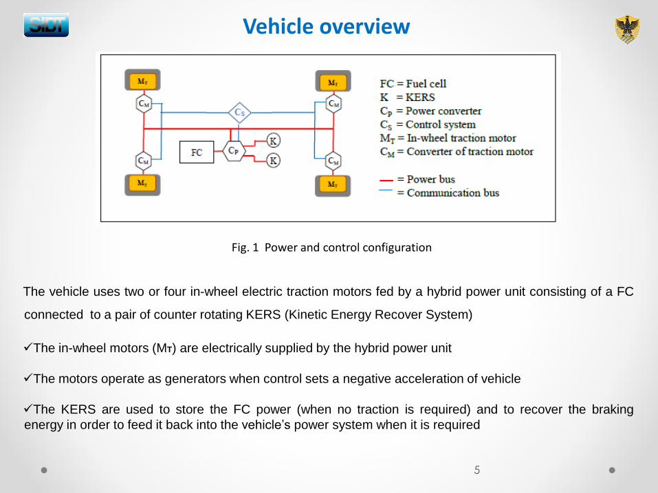
Fig. 1 Power and control configuration
The vehicle uses two or four in-wheel electric traction motors fed by a hybrid power unit consisting of a FC
connected to a pair of counter rotating KERS (Kinetic Energy Recover System)
The in-wheel motors (MT) are electrically supplied by the hybrid power unit
The motors operate as generators when control sets a negative acceleration of vehicle
The KERS are used to store the FC power (when no traction is required) and to recover the braking
energy in order to feed it back into the vehicle’s power system when it is required
5
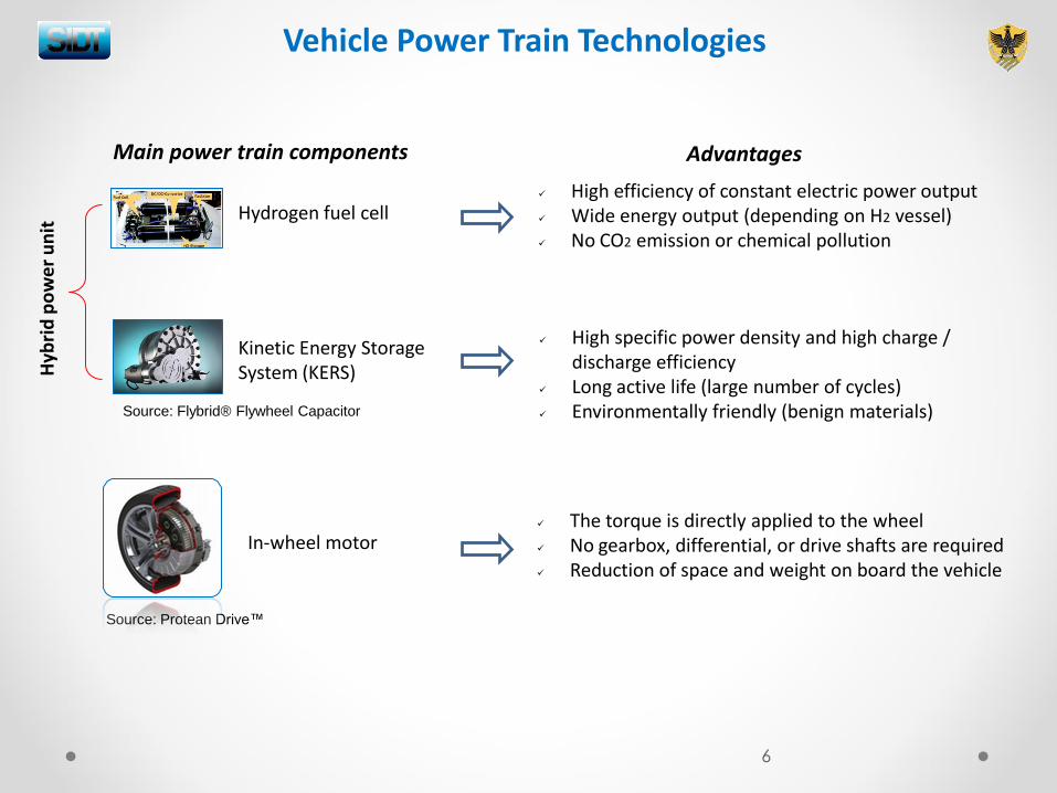
Vehicle Power Train Technologies
Kinetic Energy Storage System (KERS)
In-wheel motor
Hydrogen fuel cell
Main power train components
Hyb
rid
po
we
r u
nit
Advantages
High efficiency of constant electric power output Wide energy output (depending on H2 vessel) No CO2 emission or chemical pollution
The torque is directly applied to the wheel No gearbox, differential, or drive shafts are required Reduction of space and weight on board the vehicle
High specific power density and high charge / discharge efficiency
Long active life (large number of cycles) Environmentally friendly (benign materials)
6
Source: Flybrid® Flywheel Capacitor
Source: Protean Drive™
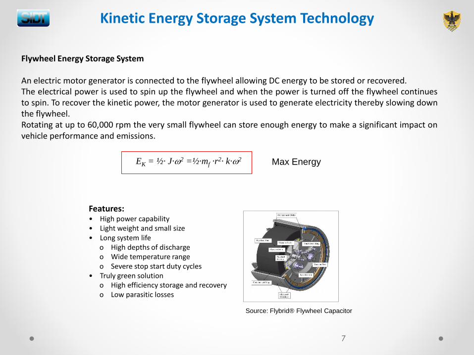
Features: • High power capability • Light weight and small size • Long system life
o High depths of discharge
o Wide temperature range o Severe stop start duty cycles • Truly green solution
o High efficiency storage and recovery o Low parasitic losses
Flywheel Energy Storage System
An electric motor generator is connected to the flywheel allowing DC energy to be stored or recovered. The electrical power is used to spin up the flywheel and when the power is turned off the flywheel continues to spin. To recover the kinetic power, the motor generator is used to generate electricity thereby slowing down the flywheel. Rotating at up to 60,000 rpm the very small flywheel can store enough energy to make a significant impact on vehicle performance and emissions.
EK = ½· J·2 =½·mf ·r2· k·2
Kinetic Energy Storage System Technology
7
Max Energy
Source: Flybrid® Flywheel Capacitor
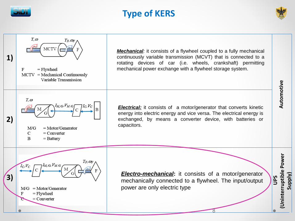
Type of KERS
Mechanical: it consists of a flywheel coupled to a fully mechanical
continuously variable transmission (MCVT) that is connected to a
rotating devices of car (i.e. wheels, crankshaft) permitting
mechanical power exchange with a flywheel storage system.
Electrical: it consists of a motor/generator that converts kinetic
energy into electric energy and vice versa. The electrical energy is
exchanged, by means a converter device, with batteries or
capacitors.
Electro-mechanical: it consists of a motor/generator
mechanically connected to a flywheel. The input/output
power are only electric type
1)
2)
3)
Au
tom
oti
ve
UP
S
(Un
inte
rru
pti
ble
Po
we
r Su
pp
ly)
8
Model of vehicle and its components
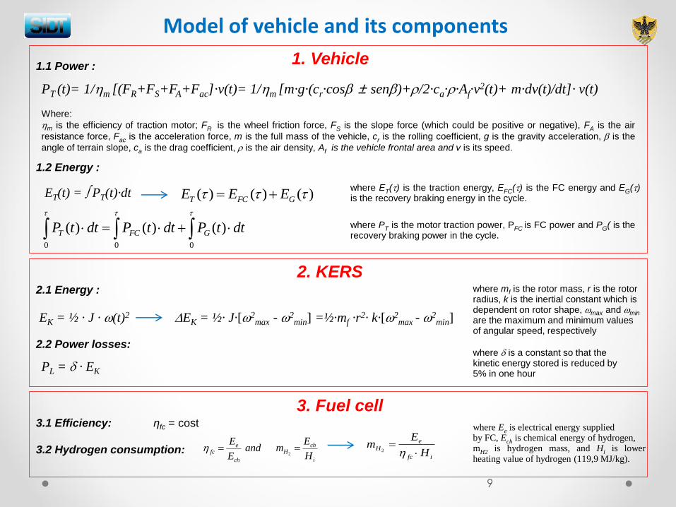
1. Vehicle
Where:
m is the efficiency of traction motor; FR is the wheel friction force, FS is the slope force (which could be positive or negative), FA is the air
resistance force, Fac is the acceleration force, m is the full mass of the vehicle, cr is the rolling coefficient, g is the gravity acceleration, is the
angle of terrain slope, ca is the drag coefficient, is the air density, Af is the vehicle frontal area and v is its speed.
PT (t)= 1/m [(FR+FS+FA+Fac]·v(t)= 1/m [m·g·(cr·cos ± sen)+/2·ca··Af·v2(t)+ m·dv(t)/dt]· v(t)
ET(t) = PT(t)·dt
1.2 Energy :
1.1 Power :
)()()( GFCT EEE where ET() is the traction energy, EFC() is the FC energy and EG() is the recovery braking energy in the cycle.
dttPdttPdttP GFCT )()()(000
where PT is the motor traction power, PFC is FC power and PG( is the recovery braking power in the cycle.
2. KERS
EK = ½ · J · (t)2
2.1 Energy :
EK = ½· J·[2max -
2min] =½·mf ·r
2· k·[2max -
2min]
where mf is the rotor mass, r is the rotor radius, k is the inertial constant which is dependent on rotor shape, max and min are the maximum and minimum values of angular speed, respectively
PL = · EK
2.2 Power losses:
3. Fuel cell
where is a constant so that the kinetic energy stored is reduced by 5% in one hour
ηfc = cost 3.1 Efficiency:
3.2 Hydrogen consumption: ifc
eH
H
Em
2and
E
E
ch
efc
i
chH
H
Em
2
where Ee is electrical energy supplied by FC, Ech is chemical energy of hydrogen, mH2 is hydrogen mass, and Hi is lower heating value of hydrogen (119,9 MJ/kg).
9
Vehicle features
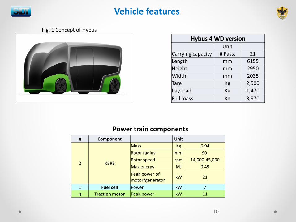
Fig. 1 Concept of Hybus
Hybus 4 WD version Unit
Carrying capacity # Pass. 21
Length mm 6155
Height mm 2950
Width mm 2035
Tare Kg 2,500
Pay load Kg 1,470
Full mass Kg 3,970
Power train components
# Component Unit
2 KERS
Mass Kg 6.94
Rotor radius mm 90
Rotor speed rpm 14,000-45,000
Max energy MJ 0.49
Peak power of motor/generator
kW 21
1 Fuel cell Power kW 7
4 Traction motor Peak power kW 11
10
Urban drive cycle model
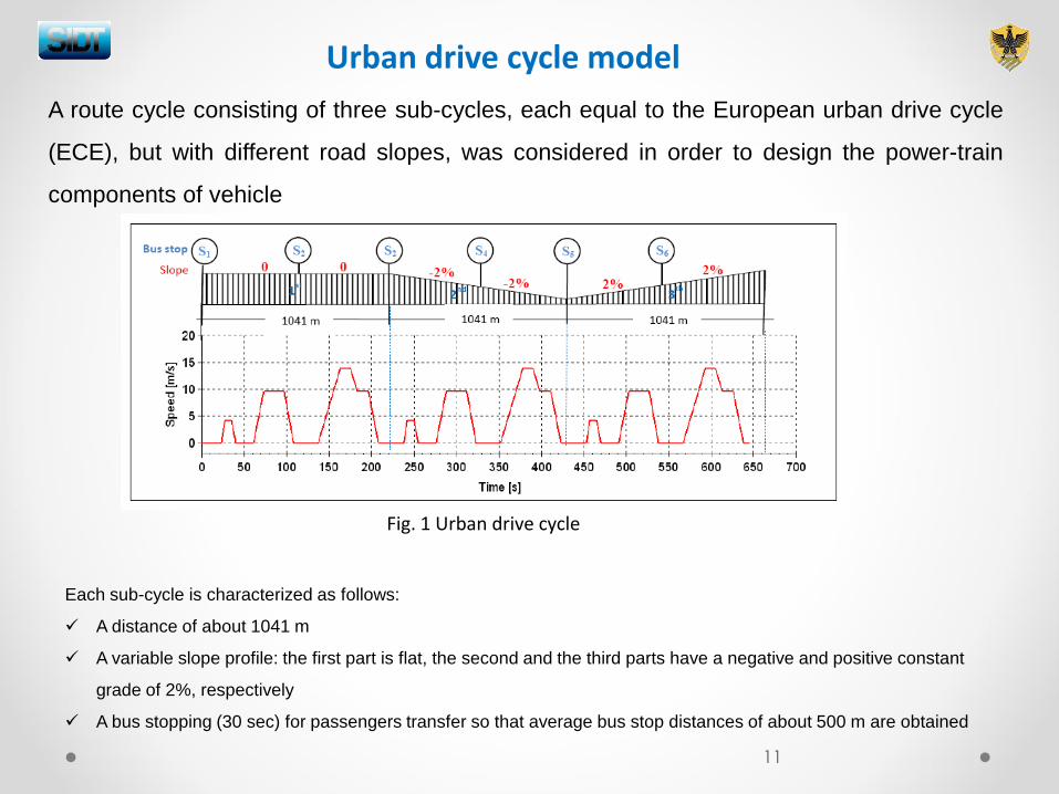
A route cycle consisting of three sub-cycles, each equal to the European urban drive cycle
(ECE), but with different road slopes, was considered in order to design the power-train
components of vehicle
Fig. 1 Urban drive cycle
Each sub-cycle is characterized as follows:
A distance of about 1041 m
A variable slope profile: the first part is flat, the second and the third parts have a negative and positive constant
grade of 2%, respectively
A bus stopping (30 sec) for passengers transfer so that average bus stop distances of about 500 m are obtained
11
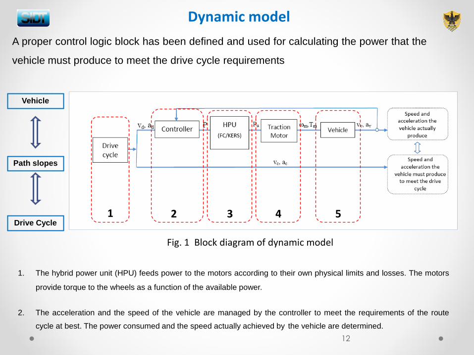
Fig. 1 Block diagram of dynamic model
Dynamic model
1 2 3 4 5
1. The hybrid power unit (HPU) feeds power to the motors according to their own physical limits and losses. The motors
provide torque to the wheels as a function of the available power.
2. The acceleration and the speed of the vehicle are managed by the controller to meet the requirements of the route
cycle at best. The power consumed and the speed actually achieved by the vehicle are determined.
A proper control logic block has been defined and used for calculating the power that the
vehicle must produce to meet the drive cycle requirements
Vehicle
Path slopes
Drive Cycle
12
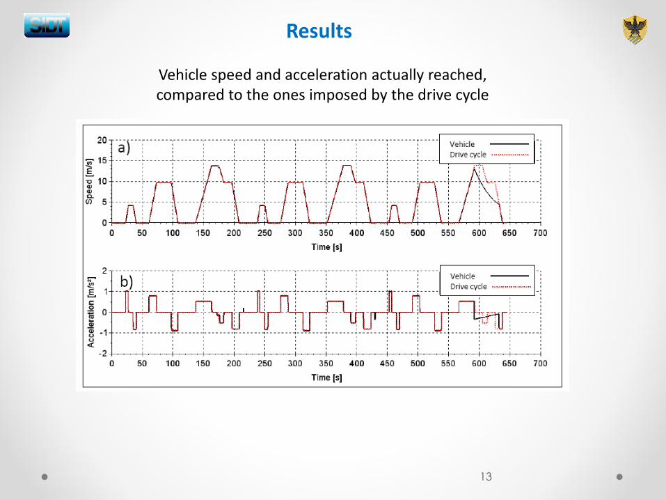
Vehicle speed and acceleration actually reached, compared to the ones imposed by the drive cycle
Results
13

The downsized FC provides the constant power of 7 kW
The KERS handles the transient loads by storing or releasing power
When the motor power request is zero the FC recharges the KERS
Results
Power profiles of fuel cell, KERS and motors
14
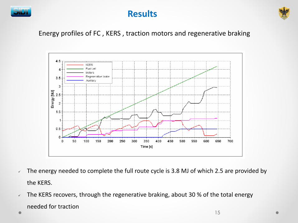
The energy needed to complete the full route cycle is 3.8 MJ of which 2.5 are provided by
the KERS.
The KERS recovers, through the regenerative braking, about 30 % of the total energy
needed for traction
Results
Energy profiles of FC , KERS , traction motors and regenerative braking
15
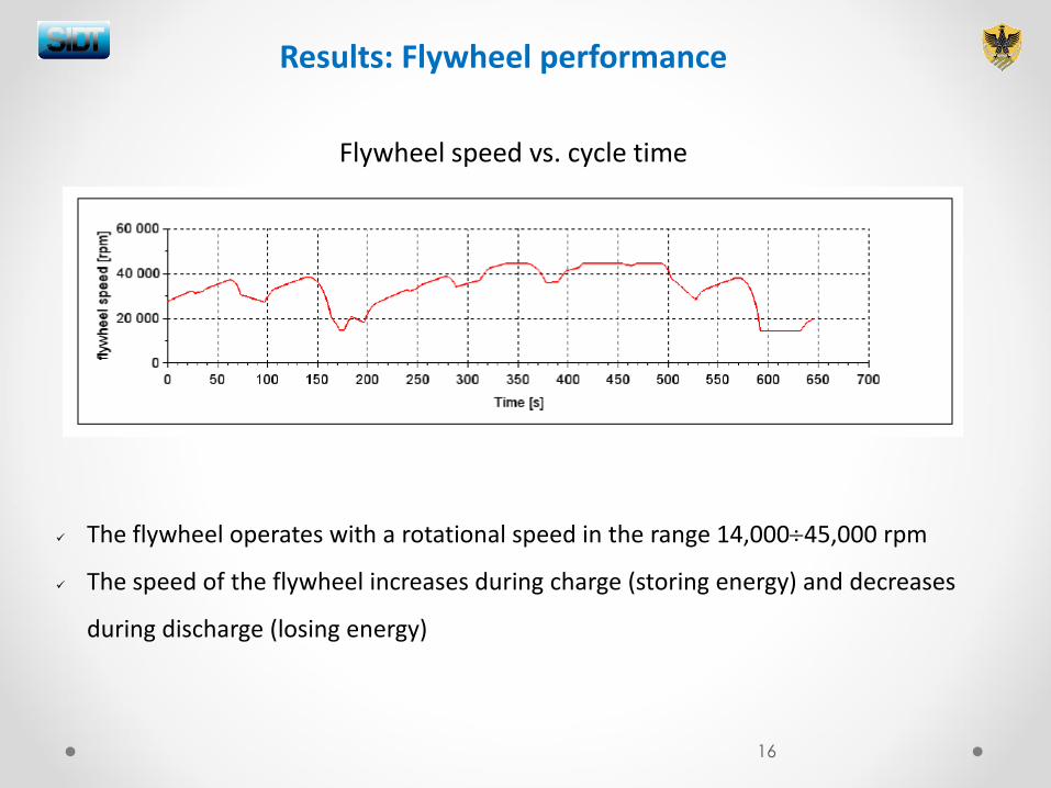
Flywheel speed vs. cycle time
The flywheel operates with a rotational speed in the range 14,00045,000 rpm
The speed of the flywheel increases during charge (storing energy) and decreases
during discharge (losing energy)
Results: Flywheel performance
16
ifc
eH
H
Em
2
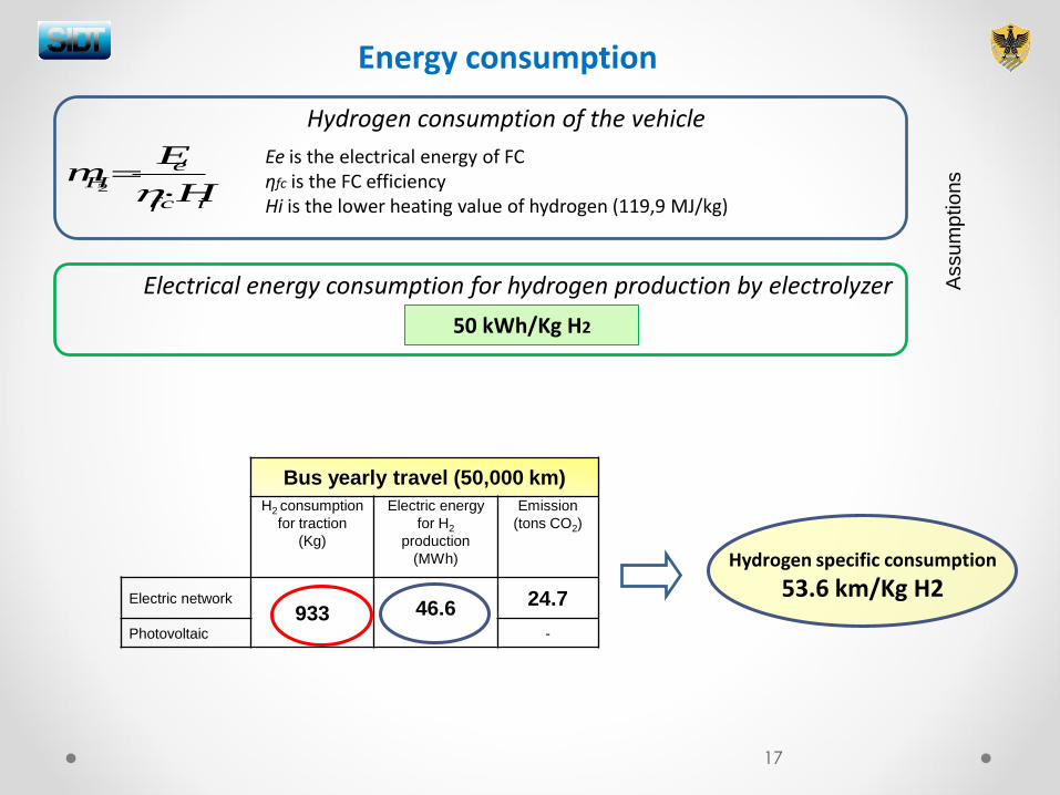
Hydrogen consumption of the vehicle
Ee is the electrical energy of FC ηfc is the FC efficiency Hi is the lower heating value of hydrogen (119,9 MJ/kg)
Energy consumption
Hydrogen specific consumption
53.6 km/Kg H2
Bus yearly travel (50,000 km)
H2 consumption
for traction
(Kg)
Electric energy
for H2
production
(MWh)
Emission
(tons CO2)
Electric network 933
46.6 24.7
Photovoltaic -
Electrical energy consumption for hydrogen production by electrolyzer
50 kWh/Kg H2
17
Assu
mp
tio
ns
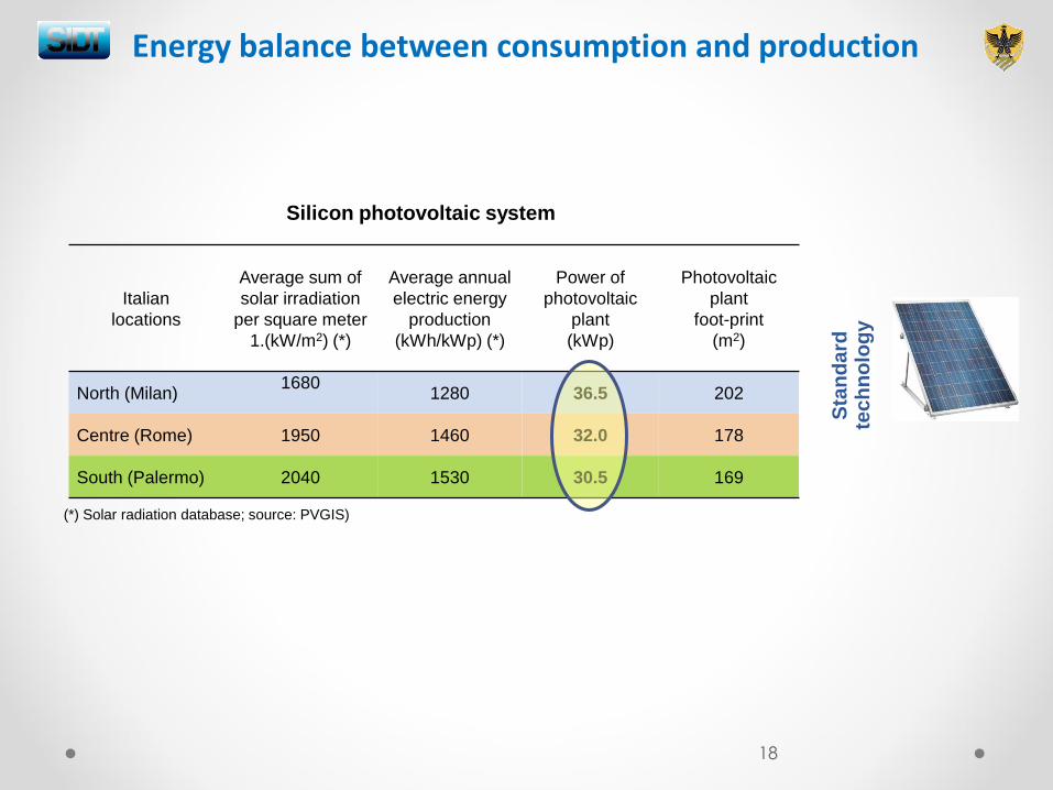
Energy balance between consumption and production
Silicon photovoltaic system
Italian
locations
Average sum of
solar irradiation
per square meter
1.(kW/m2) (*)
Average annual
electric energy
production
(kWh/kWp) (*)
Power of
photovoltaic
plant
(kWp)
Photovoltaic
plant
foot-print
(m2)
North (Milan) 1680
1280 36.5 202
Centre (Rome) 1950 1460 32.0 178
South (Palermo) 2040 1530 30.5 169
18
Sta
nd
ard
te
ch
no
log
y
(*) Solar radiation database; source: PVGIS)
Conclusions
The electric bus powertrain components (hydrogen fuel cell, KERS and traction motors) have been modeled for the European urban drive cycle.
The energy balance for a yearly travel of 50,000 km shows: - 933 Kg of hydrogen consumption for traction requirements - 46.6 MWh of electric energy for hydrogen production by electrolyzer - A photovoltaic plant of 32 kWp in Rome (standard technology)
An integrated urban public system mobility based on solar-hydrogen cycle has been proposed and analyzed
19
The main components of system have been technologically defined
«Zero» emission energy cycle has been achieved without the use of electrochemical batteries for traction

Thank you for attention
20