Embed Size (px)
Citation preview
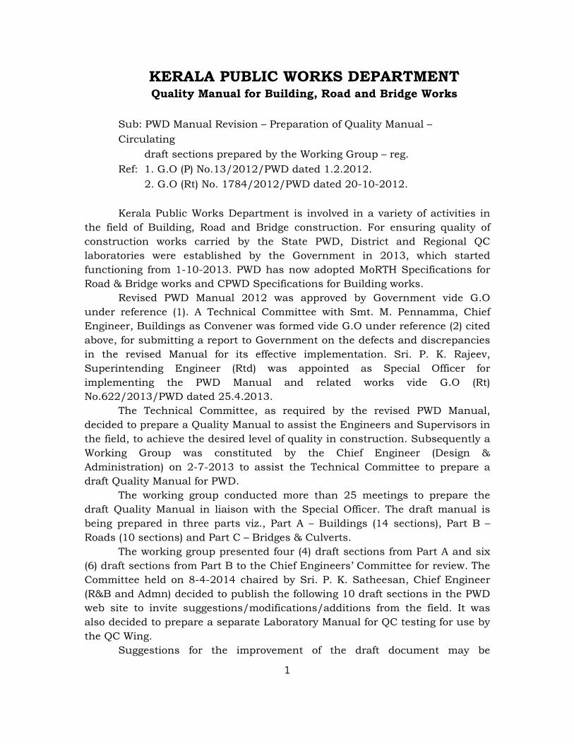
KERALA PUBLIC WORKS DEPARTMENTQuality Manual for Building, Road and Bridge Works
Sub: PWD Manual Revision – Preparation of Quality Manual –
Circulating
draft sections prepared by the Working Group – reg.
Ref: 1. G.O (P) No.13/2012/PWD dated 1.2.2012.
2. G.O (Rt) No. 1784/2012/PWD dated 20-10-2012.
Kerala Public Works Department is involved in a variety of activities in
the field of Building, Road and Bridge construction. For ensuring quality of
construction works carried by the State PWD, District and Regional QC
laboratories were established by the Government in 2013, which started
functioning from 1-10-2013. PWD has now adopted MoRTH Specifications for
Road & Bridge works and CPWD Specifications for Building works.
Revised PWD Manual 2012 was approved by Government vide G.O
under reference (1). A Technical Committee with Smt. M. Pennamma, Chief
Engineer, Buildings as Convener was formed vide G.O under reference (2) cited
above, for submitting a report to Government on the defects and discrepancies
in the revised Manual for its effective implementation. Sri. P. K. Rajeev,
Superintending Engineer (Rtd) was appointed as Special Officer for
implementing the PWD Manual and related works vide G.O (Rt)
No.622/2013/PWD dated 25.4.2013.
The Technical Committee, as required by the revised PWD Manual,
decided to prepare a Quality Manual to assist the Engineers and Supervisors in
the field, to achieve the desired level of quality in construction. Subsequently a
Working Group was constituted by the Chief Engineer (Design &
Administration) on 2-7-2013 to assist the Technical Committee to prepare a
draft Quality Manual for PWD.
The working group conducted more than 25 meetings to prepare the
draft Quality Manual in liaison with the Special Officer. The draft manual is
being prepared in three parts viz., Part A – Buildings (14 sections), Part B –
Roads (10 sections) and Part C – Bridges & Culverts.
The working group presented four (4) draft sections from Part A and six
(6) draft sections from Part B to the Chief Engineers’ Committee for review. The
Committee held on 8-4-2014 chaired by Sri. P. K. Satheesan, Chief Engineer
(R&B and Admn) decided to publish the following 10 draft sections in the PWD
web site to invite suggestions/modifications/additions from the field. It was
also decided to prepare a separate Laboratory Manual for QC testing for use by
the QC Wing.
Suggestions for the improvement of the draft document may be
1
forwarded to Sri. T. Santhosh Kumar, Director (I&QC), Office of the Chief
Engineer (Design), Thiruvananthapuram – 695 033 by post or by e-mail to
[email protected], to reach by not later than 9th May 2014.
The whole-hearted support and co-operation of all concerned is
requested.
M. Pennamma
Chief Engineer, (Buildings)
Attachments: Convener, Technical Committee
Part A – Draft sections 500, 700, 800 & 1100.
Part B – Draft sections 3200, 3300, 3400, 3500, 3600 & 3700.
2


Confidential - For private circulation only
SECTION 500: SCAFFOLDINGS
CONTENTS
501 GENERAL
502 DIFFERENT SYSTEMS
503 TIMBER/BAMBOO SCAFFOLDING
503.1 Single Scaffolding
503.2 Double Scaffolding
503.3 Requirements
504 STEEL SCAFFOLDING
504.1 Independent scaffold 504.2 Putlog scaffold
504.3 Individual Component Type Scaffold
504.4 Unit Frame Type scaffold
504.5 Materials
505 REQUIREMENTS
506 STEEL FITTINGS
506.1 Steel sections, Bars and Rivets
506.2 Bolts and Nuts
506.3 Finish
506.4 Marking
507 MANUFACTURER’S CERTIFICATE
508 DISMANTLING OF METAL SCAFFOLDS
*****
1
SECTION 500: SCAFFOLDINGS
501 GENERAL
Scaffolding is a temporary structure erected during construction for supporting labour
and materials in order to execute masonry, plastering and other items of work. It is
very essential that scaffolding should be strong enough and safe so that accidents do
not occur due to its failure.
a) A scaffold consists of upright members called standards, longitudinal horizontal
members parallel to the wall called stringers and cross horizontal members at
right angle to the wall called putlogs. Over the putlogs, planks are provided to
form a platform which serves as working space for workers and stacking space
for materials.
b) In order to distribute concentrated loads from standards on the ground, these
are supported on base plates of suitable size. On the other side of platform,
plank on edge called ‘toe board’ is provided to prevent falling down of materials, and also a guard rail is provided for safety of workers.
c) Sometimes, it is necessary for workmen to execute certain items of work – such
as application of finish coats to external walls at a height which cannot be
reached by ladders and it is not economical to go in for normal scaffolding for
that purpose. In such situations, a cradle with working platform, suspended by
ropes from the roof terrace, is provided. The cradle is held in position or moved
sideways or up and down by a few workers stationed on the terrace.
502 DIFFERENT SYSTEMS
There are two systems of scaffolding, namely ‘single scaffolding ‘and ‘double scaffolding’.
a) In case of single scaffolding there is only one row of standards at some distance
from the wall and putlogs are supported by stringers on one end and on wall
masonry at the other end
b) In case of ‘double scaffolding’ two rows of standards are provided and two ends
of putlogs rest on stringers only.
Two types of scaffold namely ‘timber/bamboo scaffold’ and ‘steel scaffold’ are mainly
used in construction.
503 TIMBER/BAMBOO SCAFFOLDING
Timber or Bamboo scaffolding could be either single or double.
503.1 Single Scaffolding
Row of standards should be at a distance of 1.2 to 1.5 m from the wall.
a) Standards should be 1.8 to 2.4 m apart and connected horizontally by
stringers, spaced vertically at 1.5 to 1.8 m centers.
b) Putlogs with one end resting on stringers and tied to them and the other end
resting in holes in masonry, should be spaced horizontally 1.2 or less apart
(usually half the spacing of standards).
2
c) Nominal diameter of standards should not be less than 8cm subject to a
minimum of 5 cm at the thin end. When it is necessary to extent a standard,
overlap between two standards should be at least 60 cm.
503.2 Double Scaffolding
a) One row of standards should be close to the wall and the other 1.2 to 1.5 m
away from the wall.
b) Nominal diameter of standards should not be less than 10cm, subject to
minimum of 5 cm at the thin end.
c) For extension of standards over-lapping should be done as for single
scaffolding.
d) Inside and outside scaffolding should be interconnected by cross-ledgers
passing through openings in masonry with a view to obtaining better stability.
503.3 Requirements
a) Scaffolding should be provided with diagonal bracings for stiffening it in the
longitudinal direction so as to prevent its distortion.
b) It should also be tied to the structure at suitable intervals to prevent it from
leaning away from the structure.
c) In case of a tall structure with a view of increasing stability of scaffolding, it is
desirable to embed the standards in ground to extend of 60 cm, supported over
base plate. If it is not feasible, standards may be supported in steel barrels of
about 60cm height, filled with soil which should be well rammed after filling it
into the barrels.
d) Standards, stringers and putlogs shall be of round poles and planks for the
platform shall have section of 20cm x 3.5 to 4.0cm.
e) Ends of planks may be hooped to prevent their splitting, thus prolonging their
life.
f) Standards, stringers and putlogs could also be of sawn timber in which case
their minimum sections should be 7x7cm, 7x5cmand 5x5cm respectively.
g) Lashing of various members of scaffolding should be done with strong fiber
ropes, applying non-slip knots.
h) When bamboo poles are used as standards, horizontal members should be tied
to the verticals just above a knot of the vertical bamboo.
i) Toe boards and guard rails are fixed to platform/standards by nailing. Planks of
the platform at their heading joints are butted with two putlogs placed at this
part about 10 cm apart to support the ends.
j) Scaffolding for stone masonry structures has to be stronger than that for brick
masonry structures, in view of heavier weight of masonry units. This could be
done by reducing the spacing of standards and putlogs and using thicker
planks for the platform.
3
504 STEEL SCAFFOLDING
Metal scaffoldings have advantages over the conventional type of timber scaffoldings
such as ease and rapidness with which they may be erected, dismantled, stored and
reused, rigidity of construction and more reliable assessment of their performance.
a) Metal scaffoldings can be constructed from steel or aluminium alloy tubes and
fittings.But almost all the metal scaffoldings used in country at present are
constructed from steel tubes and fittings.
b) Tubes and fittings covered in this manual are intended only for the usage and
loading conditions customary in normal building construction practice.
Different types of metal scaffold used in construction work are detailed below.
504.1 Independent scaffold.
a) The scaffolding is supported on two rows of uprights, independent of the
structure under construction. It may be either ‘individual component type’ or ‘unit frame type’.
b) For tall buildings, the independent scaffolding is tied to the structure at
suitable intervals for additional stability.
504.2 Putlog scaffold
The Scaffold supported by single row of uprights in combination with load bearing
parts of the structure. It may be either ‘individual component type’ or ‘unit frame type’. 504.3 Individual Component Type Scaffold
Independent or putlog Scaffold consisting of an assembly of individual tubes and
fittings.
504.4 Unit Frame Type scaffold
Independent or putlog scaffold consisting of an assembly of prefabricated frames
suitably connected or fitted and used in combination with or without individual tubes.
504.5 materials
a) Steel tubes for individual component type scaffolding shall be heavy class
welded or seamless tubes of 40 mm nominal bore conforming to IS: 1161-1963
Specification for Steel Tubes for Structural Purposes (Revised)
b) For other types of scaffoldings, the individual tube or tubes forming part of the
unit frame shall conform to the requirements of IS: 1161-1963.
c) The sizes of such tubes shall be governed by the design requirements stated
below and the minimum thickness of metal for such tubes shall conform to 6.3
of IS: 806-1957- Code of Practice for Use of Steel Tubes in General Building
Construction.
505 REQUIREMENTS
All types of scaffoldings shall be capable of carrying and transmitting to the ground,
all resultant loads by themselves or jointly with load carrying parts of the building,
which have achieved adequate strength for this purpose.
4
a) The loading on the scaffoldings shall comply with the appropriate requirements
of relevant Indian Standards regarding loading on temporary structures and
scaffoldings.
b) All scaffoldings shall be adequately stiffened, both longitudinally and
transversely to take up horizontal loading due to wind pressure on the
scaffolding or tensioning ropes, if any, or both; and the forces resulting from
inclined supports or support derived from the parts of a structurally stable
building, lifting tackle, etc.
c) The scaffoldings shall be adequately rigid at all stages of erection and
dismantling.
d) Where the supports cannot be fixed vertically due to any reason, the
eccentricity of the loading so carried should also be taken into account.
e) The braces should be designed to carry, in addition to anyapplied horizontal
loads, and the horizontal loads induced by the non-vertical supports, an
additional horizontal load equal to 1/100 of the vertical loads carried by each
platform and applied on its upper surface, and 1/100 of vertical loads carried
by the ground applied at the base of scaffolding.
f) The permissible stresses and other design considerations shall comply with the
appropriate requirements of relevant Indian Standards on structural design of
tubular steel scaffolding.
506 STEEL FITTINGS
a) All fittings shall be manufactured from steel which when analysed in
accordance with the relevant part of IS: 228 - Methods of Chemical Analysisof
pig Iron, Cast Iron, and Plain Carbon and Low Alloy Steels.
b) Shall show not more than 0.06 percent of sulphur, and not more than 0.06
percent of phosphorous and shall also conform to steels of schedule II of IS :
1570-1961 -Schedule for Wrought Steels for General Engineering Purposes.
506.1 Steel sections, Bars and Rivets
a) Steel sections and bars shall conform to IS: 226-1975 - Specification for
Structural Steel (Standard Quality) (Fifth revision).
b) Rivet bars shall conform to IS:1148-1975 - Specification for Hot Rolled Steel
Rivet Bars (Up to 40mm Diameter) for Structural Purposes (First Revision).
506.2 Bolts and Nuts
Bolts and nuts shall have mechanical properties not less than those specified in table
5 (4D) of IS:1367:1967 - Technical Supply Conditions of Threaded Fasteners (First
Revision) and shall also conform to the requirements of IS: 1362-1962 - Dimensions
for Screw Threads for general Purposes (Diameter Range 1.6 to 39mm) (Revised)
applicable.
506.3 Finish
a) If not galvanized and unless otherwise specified, the tubes and frames shall be
painted or varnished externally throughout their exposed surface.
5
b) The steel sections shall also be suitably painted or otherwise treated for
protection against rust and corrosion.
c) All fittings shall be suitably treated soas to render them resistant to corrosion.
506.4 Marking
a) Tubes, fittings and prefabricated frames shall have manufacturers name or
trade mark and other information.
b) Tubes fittings and prefabricated frames shall also have BIS certification mark.
507 MANUFACTURER’S CERTIFICATE
a) The manufacturer or supplier shall also produce manufacturer’s certificate
(either calculations or test data) in fulfillment of the design criteria.
b) Where so required by the Engineer, the manufacturer or supplier shall furnish
and wherever possible suitably exhibit on the scaffolding, the following
particulars:
i. Design load which may be imposed on the scaffolding as a whole, and the
distribution of this load upon which the design of trestles, tripods or unit
frames is based;
ii. Limitations of height, width or breadth in any direction, with or without
supports derived from the structure;
iii. Maximum distance to which the scaffolding can be extended beyond a given
dimension in any direction, and the type of support required for the
purpose; and
iv. Any other restrictions on the usage or transportation of scaffoldings, fittings,
prefabricated frames and components.
508 DISMANTLING OF METAL SCAFFOLDS
Dismantling sequence should be planned and that sequence of dismantling sections of
the scaffold should be logical and determined with due consideration of the scaffolder’s
safety.
a) Dismantling work should proceed generally from the top in horizontal sections.
b) Scaffolds should not be dismantled in vertical sections from one end towards
the other unless special consideration is given to ties and bracings.
c) All materials should be lowered to the ground and not stored on the scaffold.
REFERENCES:
1. Bureau of Indian standards: Hand book on masonry design and Construction
(First revision).
2. Code of practice for Metal Scaffolding safety by Occupational safety and Health
Branch, Labour Department (Hong Kong).
3. IS: 2750-1964-Specification for Steel Scaffoldings.
Confidential - For private circulation only
SECTION 700: DOORS AND WINDOWS
CONTENTS
701 GENERAL 702 TIMBER
702.1 Moisture Content
702.2 Seasoning of Timber
702.3 Quality Tests
703 FRAMES FOR DOOR, WINDOW AND VENTILATOR
704 SHUTTERS – PANELLED, GLAZED OR PANELLED AND GLAZED
705 FLUSH DOOR SHUTTERS
705.1 Tests for flush doors
705.1.1 End immersion test
705.1.2 Knife test
705.1.3 Glue adhesion test
705.1.4 Quality control tests 706. STEEL DOORS AND WINDOWS
706.1 Materials
706.2 Sampling and criteria for conformity
707. PRESSED STEEL DOORS & WINDOWS
707 PVC DOORS
707.1 Quality Control Tests
708. ALUMINIUM DOORS AND WINDOWS
708.1 Side-hung Shutters
708.2 Top-Hung Ventilators
708.3 Centre-Hung Ventilators
708.4 Fittings
709 FIBRE GLASS REINFORCED PLASTIC (FRP) DOORS
710 SOLID PVC FOAM PROFILE DOORS
711 LAMINATED VENEER LUMBER (LVL)
712. UPVC DOOR FRAME
713. FITTINGS
713.1Butt Hinges
713.2 Parliament hinges
713.3 Spring Hinges
713.4 Door Handles (Doors and Windows)
713.5 Floor Door Stopper
713.6 Door closers 713.7 Mortice locks 713.7.1 Test for mortice locks
*****
1
SECTION 700: DOORS AND WINDOWS 701 GENERAL
The main function of a door in a building is to serve as a connecting link between the
internal parts and to allow free movement to the outside of the building. Windows are
generally provided for the proper ventilation and lighting of a building and their size
and number should be properly determined as per the requirements. The
requirements for wooden, steel, aluminium, PVC doors and windows are given in this
section.
702 TIMBER
a) The timber shall be free from decay, fungal growth, boxed heart, pitch
pockets or streaks on the exposed edges, splits and cracks.
b) The timber shall be graded as first grade and second grade on the basis of
the permissible defects in the timber as given in Appendix A (Clause 9.1) of
CPWD specifications 2009.
c) For both the grades, knots should be avoided over a specified limit.
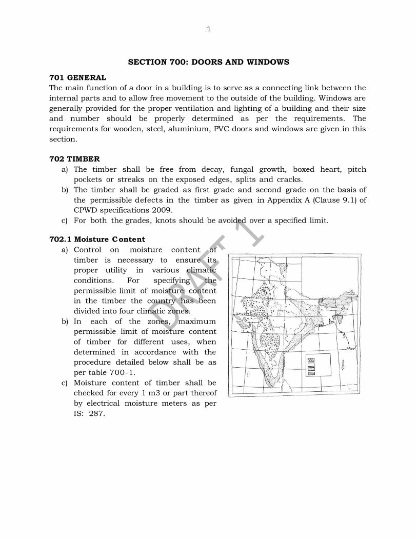
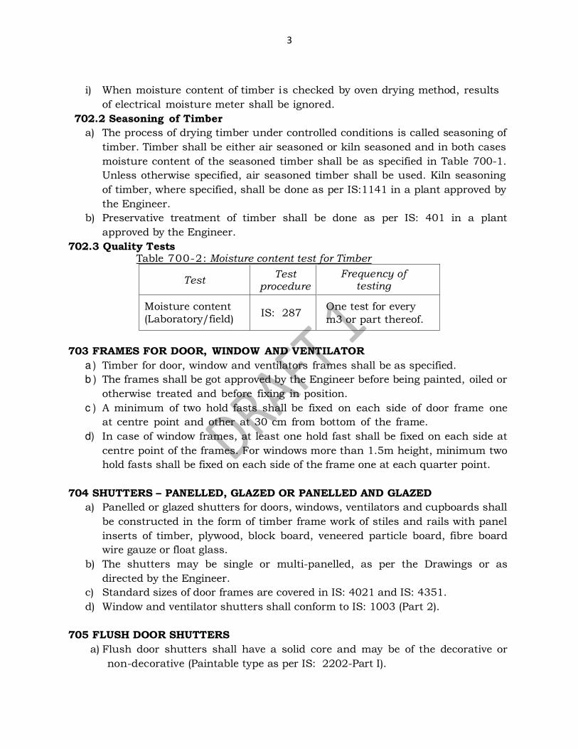
702.1 Moisture Content
a) Control on moisture content of
timber is necessary to ensure its
proper utility in various climatic
conditions. For specifying the
permissible limit of moisture content
in the timber the country has been
divided into four climatic zones.
b) In each of the zones, maximum
permissible limit of moisture content
of timber for different uses, when
determined in accordance with the
procedure detailed below shall be as
per table 700-1.
c) Moisture content of timber shall be
checked for every 1 m3 or part thereof
by electrical moisture meters as per
IS: 287.
2
Table 700-1: Maximum Permissible Moisture Content of Timber
Sl.No Use Max Moisture Content Percent Zone Zone Zone Zone
I II III IV 1. Beams, Rafters & Posts 12 14 17 20
2.
Doors and windows (a) 50 mm and above thickness
10 12 14 16 (b) Thinner than 50 mm 8 10 12 14
3. Flooring strips 8 10 10 12
4. Furniture and cabinet making
10 12 14 15
d) Average moisture content of all the samples from a lot shall be within +3%
and moisture content of individual samples within +5% of maximum
permissible moisture content specified in Table 700-1 . These tolerances are
the absolute values over the percentage moisture content for Sl. Nos. 1 & 2 of
Table 700-1. No tolerance on moisture content is permitted for Sl. No. 3 & 4 of
Table 700-1.
e) If for any reason, whatsoever, the readings of electrical moisture meter are
not to be relied upon, the moisture content shall be checked by the oven
drying method.
f) For checking moisture content by oven drying method, a complete test
cross section, 12 to 19 mm long in the direction of timber grain, free from
all defects shall be cut from each piece of timber selected. If weighing can
be done immediately, the test section shall be cut from a point at least 45
cm from one end of the piece or from its centre.
g) In case cutting of test section from the piece is not permissible the moisture
content in the whole section can also be determined by collecting a boring to a
depth of half of the thickness of the piece by means of an auger, in a pre-
weighed weighing bottle which should then be sealed properly.
h) The test sections obtained above shall be weighed, immediately after cutting,
on a balance the sensitivity of which i s not less than 10 mg. They shall be
dried in a ventilated, and preferably thermostatically controlled, oven at a
temperature of 100°C to 105°C until the weight is constant. The weight of
the test section shall be deemed to have become constant if successive
weighing at intervals of 2 to 5 hours does not differ from one another by
more than 50 mg. The test weight shall be taken to be the oven dry weight of
the test section. The percentage moisture content in the test section shall be
calculated as below:
Moisture content (% ) = [(W 1-W2 )/W2 ] x100
where, W1 = Initial weight of test section and
W2 = Oven dry weight of test section
3
i) When moisture content of timber is checked by oven drying method, results
of electrical moisture meter shall be ignored.
702.2 Seasoning of Timber
a) The process of drying timber under controlled conditions is called seasoning of
timber. Timber shall be either air seasoned or kiln seasoned and in both cases
moisture content of the seasoned timber shall be as specified in Table 700-1.
Unless otherwise specified, air seasoned timber shall be used. Kiln seasoning
of timber, where specified, shall be done as per IS:1141 in a plant approved by
the Engineer.
b) Preservative treatment of timber shall be done as per IS: 401 in a plant
approved by the Engineer.
702.3 Quality Tests Table 700-2: Moisture content test for Timber
Test Test
procedure
Frequency of testing
Moisture content
(Laboratory/field) IS: 287
One test for every
m3 or part thereof.
703 FRAMES FOR DOOR, WINDOW AND VENTILATOR
a ) Timber for door, window and ventilators frames shall be as specified.
b ) The frames shall be got approved by the Engineer before being painted, oiled or
otherwise treated and before fixing in position.
c ) A minimum of two hold fasts shall be fixed on each side of door frame one
at centre point and other at 30 cm from bottom of the frame.
d) In case of window frames, at least one hold fast shall be fixed on each side at
centre point of the frames. For windows more than 1.5m height, minimum two
hold fasts shall be fixed on each side of the frame one at each quarter point.
704 SHUTTERS – PANELLED, GLAZED OR PANELLED AND GLAZED
a) Panelled or glazed shutters for doors, windows, ventilators and cupboards shall
be constructed in the form of timber frame work of stiles and rails with panel
inserts of timber, plywood, block board, veneered particle board, fibre board
wire gauze or float glass.
b) The shutters may be single or multi-panelled, as per the Drawings or as
directed by the Engineer.
c) Standard sizes of door frames are covered in IS: 4021 and IS: 4351.
d) Window and ventilator shutters shall conform to IS: 1003 (Part 2).
705 FLUSH DOOR SHUTTERS
a) Flush door shutters shall have a solid core and may be of the decorative or
non-decorative (Paintable type as per IS: 2202-Part I).
4
b) Thickness and type of shutters shall be as specified.
c) Width and height of the shutters shall be as shown in the drawings or as
indicated by the Engineer.
d) All four edges of the shutters shall be square.
e) The shutter shall be free from twist or warp in its plane.
f) The moisture content in timbers used in the manufacture of flush door
shutters shall be not more than 12 per cent when tested according to IS:
1708.
705.1 Tests for flush doors
a) Samples of flush door shutters shall be subjected to the following tests viz.,
End Immersion Test, Knife Test and Glue Adhesion Test
b) One end of each sample shutter shall be tested for End Immersion Test.
c) Two specimens of 150 mm x 150 mm size shall be cut from the two corners at
the other end of each sample shutter for carrying out Glue Adhesion Test.
d) Knife Test shall be done on the remaining portion of each sample shutter.
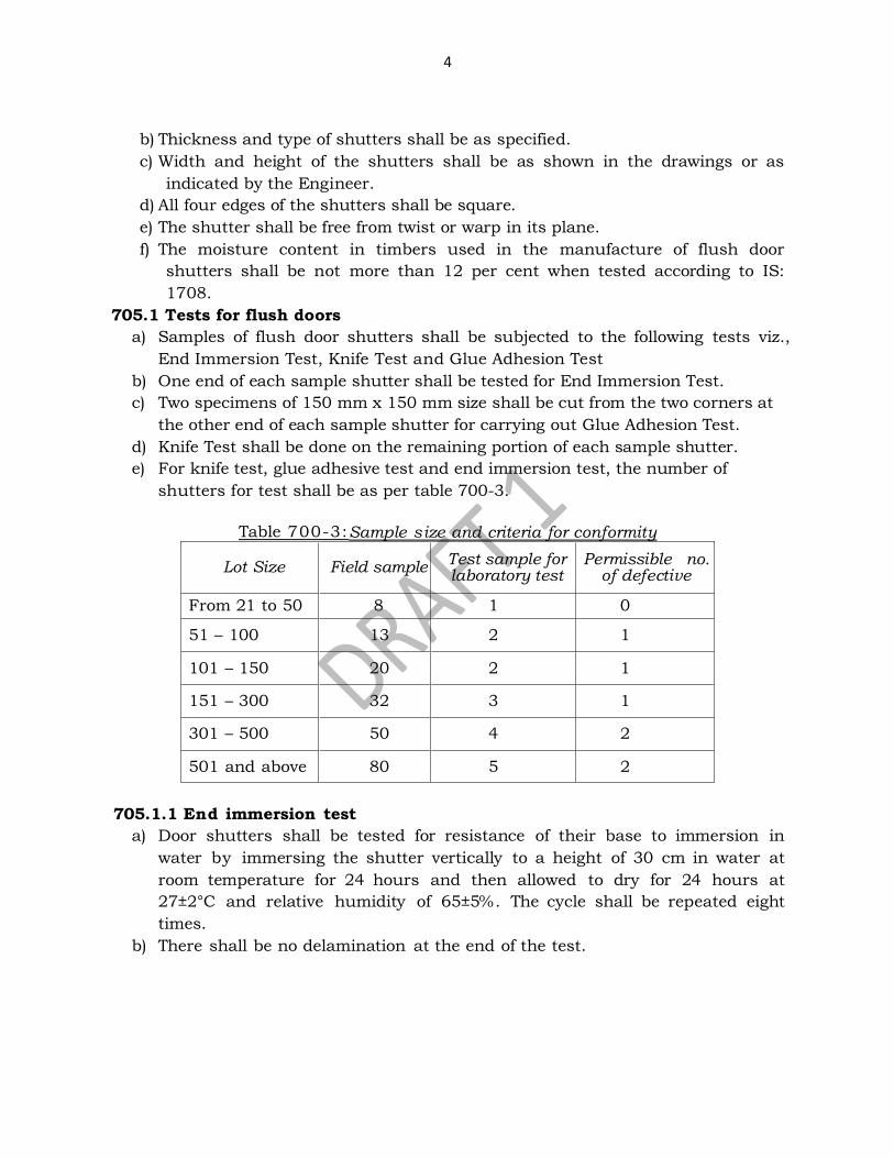
e) For knife test, glue adhesive test and end immersion test, the number of
shutters for test shall be as per table 700-3.
Table 700-3:Sample size and criteria for conformity
Lot Size Field sample Test sample for laboratory test
Permissible no. of defective
From 21 to 50 8 1 0
51 – 100 13 2 1
101 – 150 20 2 1
151 – 300 32 3 1
301 – 500 50 4 2
501 and above 80 5 2
705.1.1 End immersion test
a) Door shutters shall be tested for resistance of their base to immersion in
water by immersing the shutter vertically to a height of 30 cm in water at
room temperature for 24 hours and then allowed to dry for 24 hours at
27±2°C and relative humidity of 65±5%. The cycle shall be repeated eight
times.
b) There shall be no delamination at the end of the test.
5
25 c
m
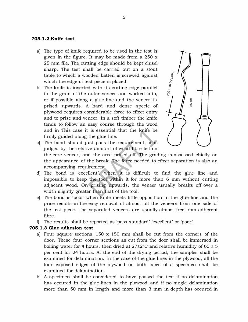
705.1.2 Knife test
a) The type of knife required to be used in the test is
given in the figure. It may be made from a 250 x
25 mm file. The cutting edge should be kept chisel
sharp. The test shall be carried out on a stout
table to which a wooden batten is screwed against
which the edge of test piece is placed.
b) The knife is inserted with its cutting edge parallel
to the grain of the outer veneer and worked into,
or if possible along a glue line and the veneer is
prised upwards. A hard and dense specie of
plywood requires considerable force to effect entry
and to prise and veneer. In a soft timber the knife
tends to follow an easy course through the wood
and in This case it is essential that the knife be
firmly guided along the glue line.
c) The bond should just pass the requirement, it is
judged by the relative amount of wood fibre left on
the core veneer, and the area prised off. The grading is assessed chiefly on
the appearance of the break. The force needed to effect separation is also an
accompanying requirement.
d) The bond is ‘excellent’, when it is difficult to find the glue line and
impossible to keep the tool within it for more than 6 mm without cutting
adjacent wood. On prising upwards, the veneer usually breaks off over a
width slightly greater than that of the tool.
e) The bond is ‘poor’ when knife meets little opposition in the glue line and the
prise results in the easy removal of almost all the veneers from one side of
the test piece. The separated veneers are usually almost free from adherent
fibre.
f) The results shall be reported as ‘pass standard’ ‘excellent’ or ‘poor’. 705.1.3 Glue adhesion test
a) Four square sections, 150 x 150 mm shall be cut from the corners of the
door. These four corner sections as cut from the door shall be immersed in
boiling water for 4 hours, then dried at 27±2°C and relative humidity of 65 ± 5
per cent for 24 hours. At the end of the drying period, the samples shall be
examined for delamination. In the case of the glue lines in the plywood, all the
four exposed edges of the plywood on both faces of a specimen shall be
examined for delamination.
b) A specimen shall be considered to have passed the test if no delamination
has occured in the glue lines in the plywood and if no single delamination
more than 50 mm in length and more than 3 mm in depth has occured in

6
the assembly glue lines between the plywood faces and the stile and rail.
c) Delamination at the corner shall be measured continuously around the
corner. Delamination at a knot, knot hole, a pitch pocket and worm hole or
other permissible wood defects shall not be considered in assessing the
sample.
d) A door shall be deemed to have passed this test, if three of the four
specimens tested pass the test.
705.1.4 Quality control tests
The door shutters shall be subjected to the following tests in accordance with IS:
4020 (Part 1 to 16). Table 700-4: Quality tests for door shutters
Test Test
procedure
Minimum
sample size
Frequency of
Testing
End immersion Test,
Knife test Glue
Adhesion Test
IS: 2202
21 shutters
As per sampling
and testing specified
in table 700-3.
706. STEEL DOORS AND WINDOWS 706.1 Materials
a) Rolled steel sections for the fabrication of steel doors, windows, ventilators and
fixed-lights shall conform to IS: 7452-1982. Steel used in the manufacture of
these sections shall conform to IS: 7452-1982.
b) Glass panes shall be at least at 3mm thick and shall conform to IS: 2835-1977.
All glass panes shall have properly squared corners and straight edges.
c) Screw threads of machine screws used in the manufacture of steel doors,
windows, ventilators and fixed-lights shall conform to the requirements of
IS:4218 (Parts I to VI)
d) Fixed and open frame shall be constructed of sections which have been cut to
length and mitred. The corners of fixed and opening frames shall be welded to
form solid fused welded joint conforming to the requirements. All frames shall
be square and flat. The process of welding adopted may be flash butt welding or
any other suitable method which gives the desired requirements.
e) All the steel surface shall be thoroughly cleaned free of rust, millscale, dirt, oil,
etc.
f) All doors, windows, ventilators and fixed-lights shall carry an identification of
the manufacturer or trade-mark, if any and the process of welding adopted.
g) Each unit may also be marked with BIS certification mark.
h) All doors, windows and ventilators shall be despatched with the opening parts
suitably secured to preserve alignment when fixing and glazing.
i) Fixing lugs, couplings, fittings and all hardware shall be despatched separately.
j) Composite windows shall be despatched uncoupled.
7
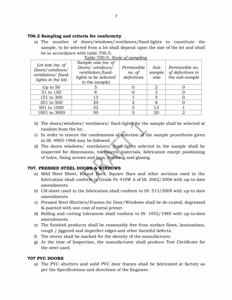
706.2 Sampling and criteria for conformity
a) The number of doors/windows/ventilators/fixed-lights to constitute the
sample, to be selected from a lot shall depend upon the size of the lot and shall
be in accordance with table 700-5. Table 700-5: Scale of sampling
Lot size (no. of Doors/windows/ ventilators/ fixed-
lights in the lot)
Sample size (no. of Doors/ windows/ ventilators fixed-
lights to be selected in the sample)
Permissible no. of
defectives
Sub sample
size
Permissible no. of defectives in the sub-sample
Up to 50 5 0 2 0
51 to 150 8 0 3 0
151 to 300 13 1 5 0
301 to 500 20 2 8 0
501 to 1000 32 3 13 1
1001 to 3000 50 5 20 2
b) The doors/windows/ ventilators/ fixed-lights for the sample shall be selected at
random from the lot.
c) In order to ensure the randomness of selection of the sample procedures given
in IS: 4905-1968 may be followed.
d) The doors windows/ ventilators/ fixed-lights selected in the sample shall be
inspected for dimensions, tolerances, materials, fabrication except positioning
of holes, fixing screws and lugs, finishing and glazing.
707. PRESSED STEEL DOORS & WINDOWS
a) Mild Steel Sheet, Round Bars, Square Bars and other sections used in the
fabrication shall conform to Grade Fe 410W A of IS: 2062/2006 with up-to date
amendments.
b) CR-sheet used in the fabrication shall conform to IS: 513/2008 with up-to date
amendments.
c) Pressed Steel Shutters/Frames for Door/Windows shall be de-rusted, degreased
& painted with one coat of metal primer.
d) Rolling and cutting tolerances shall conform to IS: 1852/1985 with up-to-date
amendments.
e) The finished products shall be reasonably free from surface flaws, laminations,
rough / jiggered and imperfect edges and other harmful defects.
f) The stores shall be marked for the identity of the manufacturer.
g) At the time of Inspection, the manufacturer shall produce Test Certificate for
the steel used.
707 PVC DOORS
a) The PVC shutters and solid PVC door frames shall be fabricated at factory as
per the Specifications and directions of the Engineer.
8
b) Shutter shall be made of PVC material conforming to IS: 10151.
c) The solid PVC door frames shall be fabricated in factory as per nomenclature of
the item and directions of the Engineer.
707.1 Quality Control Tests
a) Dimension and Squareness Test - Door shutters when tested in accordance with
IS: 4020 (Part 2) the dimensions of nominal width and height will be within a
limit of + 5 mm. The door shutter shall not deviate by more than 1 mm on a
length of 500 mm. The thickness of the door shutter shall be uniform
throughout with the permissible variation of not more than 0.8 mm between
any two points. The nominal thickness of the shutter shall be within a limit of +
1.5 mm.
b) General Flatness Test - Door shutter, when tested in accordance with IS: 4020
(Part 3) the twist, cupping and warping shall not exceed 6 mm.
c) Local Planeness Test - Door shutters, when tested in accordance with IS:
4020(Part 4), the depth of deviation measured at any point shall not be more
than 0.5 mm.
d) Impact Indentation Test - Door shutters, when tested in accordance with IS:
4020 (Part 5), shall have no defects such as cracking, tearing or delamination
and the depth of indentation shall not be more than 0.2 mm.
e) Edge Loading Test - Door shutters, when tested in accordance with IS: 4020
(Part 7) the deflection of the edge at the maximum load shall not be more than 5
mm. On removal of the loads, the residual deflection shall not be more than
0.5 mm, failing which the test may be repeated on the other edge in the reverse
direction. Also there shall be no lateral buckling by more than 2 mm during
loaded condition and no residual lateral buckling after removal of the load.
f) Shock Resistance Test - Door shutters, when tested in accordance with 2.1 of IS:
4020 (Part 8), there shall be no visible damage in any part of the door after
twenty five blows on each end.
g) Buckling Test - Door shutters, when tested in accordance with IS: 4020 (Part 9),
shall not show any deterioration and any residual deformation more than 5 mm
after 15 min. of unloading and the initial deflection also shall not be more than
50 mm.
h) Slamming Test - Door shutters, when tested in accordance with 2.1 of IS: 4020
(Part 10), shall not have any damage in any part of the door at the end of
successive impacts. Door shutters, when tested in accordance with 3.1 of IS:
4020 (Part 10), shall not have any visible damage in part of the door at the end
of 100 successive impacts.
i) Misuse Test - Door shutters, when tested in accordance with IS: 4020 (Part 11),
there shall not be any permanent deformation of the fixing or any other part of
the door set in hindering its normal working after the test.
j) Screw Holding Test - Door shutters, when tested in accordance with IS: 4020-
Part 16, the load shall not be less than 1000 N.
9
k) End Immersion Test - Door shutters, when tested in accordance with IS: 4020-
Part 13, the shutter shall not show any delamination.
l) Knife Test - Door shutter, when tested in accordance with IS: 4020 – Part 14,
the grading shall be standard & excellent.
m) Glue Adhesion Test - Door shutters when tested in accordance with IS: 4020 –
Part 15, shall not show any delamination.
708. ALUMINIUM DOORS AND WINDOWS
a) Material, fabrication and dimensions of aluminium doors, windows and
ventilators manufactured from extruded aluminium alloy sections of standard
sizes and designs complete with fittings, ready for being fixed into the building
shall be as per IS: 1948.
b) In the case of composite windows and doors, the different units are to be
assembled first. The assembled composite units shall be checked for line,
level and plumb before final fixing is done.
c) Where aluminium comes into contact with stone masonry, brick work, concrete,
plaster or dissimilar metal, it shall be coated with an approved insulation
lacquer, paint or plastic tape to ensure that electrochemical corrosion is
avoided. Insulation material shall be trimmed off to a clean flush line on
completion.
d) The contractor shall be responsible for the doors, windows etc. being set
straight, plumb, level and for their satisfactory operation after fixing is
complete.
e) Aluminium alloy extruded sections used in the manufacture of extruded
window sections shall conform to IS 733. Hollow aluminium alloy sections
used shall conform to IS: 1285.
f) Glass panes shall weigh at least 7.5 kg/m2 and shall be free from flaws, specks
or bubbles. All panes shall have properly squared corners and straight edges.
g) Screws threads of machine screws used in the fabrication of aluminium
doors, windows and ventilators shall conform to IS: 1362.
h) Frames shall be square and flat, the corners of the frame being fabricated to a
true right angle. Both the fixed and opening frames shall be constructed of
sections which have been cut to length, mitred and welded at the corners.
Where hollow sections are used with welded joints, argon-arc welding or flash
butt welding shall be employed (gas welding or brazing not to be done).
Subdividing bars of units shall be tenoned and riveted into the frame.
i) Aluminium doors, windows and ventilators may be supplied in either matt,
scratch-brush or polished finish. They may, additionally, also be anodized, if so
required by the Engineer-in-charge. If colour anodizing is to be done then
only approved light-fast shades should be used.
j) All doors, windows and ventilators shall be dispatched with the opening parts
suitably secured to preserve alignment when fixing and glazing. Fixing lugs,
10
coupling fittings and all hardware shall be dispatched separately. Composite
windows shall be dispatched uncoupled.
k) All doors, windows and ventilators shall be suitably marked on the frames with
a mark identifying the manufacturer and the type. The units may also be
marked with the BIS certification mark.
708.1 Side-hung Shutters
a) The aluminium alloy for cast hinges shall conform to IS Designation A-5-M of IS
617.
b) Specification for Aluminium and Aluminium Alloy Ingots and Castings for
General Engineering Purpose and for extruded section of hinges to IS
Designation HE10-WP or HE30-WP of IS: 733.
708.2 Top-Hung Ventilators
a) The aluminium hinges for top-hung ventilators shall be either cast or fabricated
out of extruded sections and shall be riveted to the fixed rail after cutting a slot
in it.
b) The aluminium alloy for cast hinges shall conform to IS Designation A-5-M of
IS: 617 and the extruded section of hinge to IS Designation HE10-WP or HE30-
WP of IS: 733
708.3 Centre-Hung Ventilators
Centre hung ventilators shall be hung on two pairs of cup pivots of aluminium alloy to
IS Designation NS-4 of IS 737 and IS Designation A-5-M of IS: 617 or on brass or
bronze cup pivots which should be either chromium or cadmium plated and riveted to
the inner and outer frames of the ventilators to permit the ventilator to swing through
an angle of approximately 85º.
708.4 Fittings
a) Stainless Steel Friction Stay: The stainless steel friction stays of make approved
by the Engineer shall be used. The SS friction stays shall be of grade AISI-304
and of sizes specified in nomenclature of item.
b) Lockable Handles: The lockable handle shall be of make approved by the
Engineer and of required colour to match the colour of powder coated
/anodized aluminium window sections.
c) Hydraulic Floor Spring: The hydraulic floor spring shall be heavy duty double
action floor spring of make approved by the Engineer suitable for door leaf of
weight minimum 100 kg.
d) Tubular Handle: The tubular handle bar shall be aluminium polyester powder
coated minimum 50 micron of required colour/anodized AC 15. Outer dia of
tube shall be 32 mm, tube thickness 3.0 mm and centre to centre length 2115
mm + 5 mm.
e) Louvers: Aluminium extruded sections (anodized or power coated) are used
for providing Louvers in aluminium door, window & partition for ventilation.
f) Brass lock: This should generally conform to IS: 2209. False lever shall not be

11
used. Lever shall be fitted with one spring of phosphor-bronze or steel
wire and shall withstand the test as provided in IS: 2209. Locking-bolt spring
and strike plate shall conform to IS: 2209. Two keys shall be provided with each
lock.
709 FIBRE GLASS REINFORCED PLASTIC (FRP) DOORS
FRP doors and shutters shall be manufactured as per specifications laid down in IS:
14856, nomenclature of items & direction of the Engineer.
710 SOLID PVC FOAM PROFILE DOORS
a) Solid PVC foam profile frame doors are made from solid PVC foam profiles 60
x 30 mm with integral skin cut to required size.
b) Doors are provided with naturally strong stiffener frame and sandwich
panelled to offer sound and heat insulation with pressure laminate/infill panel
to provide scratch resistance surface.
c) Tests on PVC Foam Profiles shall be as per table 700-6 below: Table 700-6: Quality tests for PVC foam profile doors
Sl. No.
Property Test
method Unit Acceptable Value
1 Density (at 27°C) ASTM D
792 gm/cc 0.5-0.7
2 Tensile strength at yield ASTM D
638 PSI % 2000
(B) Elongation at Break ASTM D
638 20
3 Tensile Modulus (Modulus of Elasticity)
ASTM D 638
N/mm2 200
4 Impact strength (charpy Unnotched)
ASTM D 256
ftIb/sq.In 7
5 Durometer Hardness DIN 53505 Shore D 70
6 Vicat Softening Point (at 10N Load)
ASTM D 1525
C 75
7 Flammability UL 94 Self Extinguishing
711 LAMINATED VENEER LUMBER (LVL)
Laminated veneer lumber door frames and shutters shall conform to IS: 14616.
712. UPVC DOOR FRAME
UPVC door frame shall be made of PVC material conforming to IS: 10151.
12
713. FITTINGS
713.1 Butt Hinges
These shall be of the following types according to the material used.
(i) Mild steel butt hinges (Medium).
(ii) Cast brass butt hinges light/ordinary or heavy.
(iii) Extruded aluminium alloy butt hinges.
713.2 Parliament hinges
These shall be of mild steel cast brass or as specified, and shall generally
conform to IS: 362.
713.3 Spring Hinges
These shall be made of MS or brass as specified, and shall generally conform to IS:
453.
713.4 Door Handles (Doors and Windows)
These should generally conform to IS: 208.
713.5 Floor Door Stopper
a) The floor door stopper shall conform to IS: 1823.
b) Aluminium stopper shall be anodised and anodic film shall not be less than
grade AC-10 of IS: 1868.
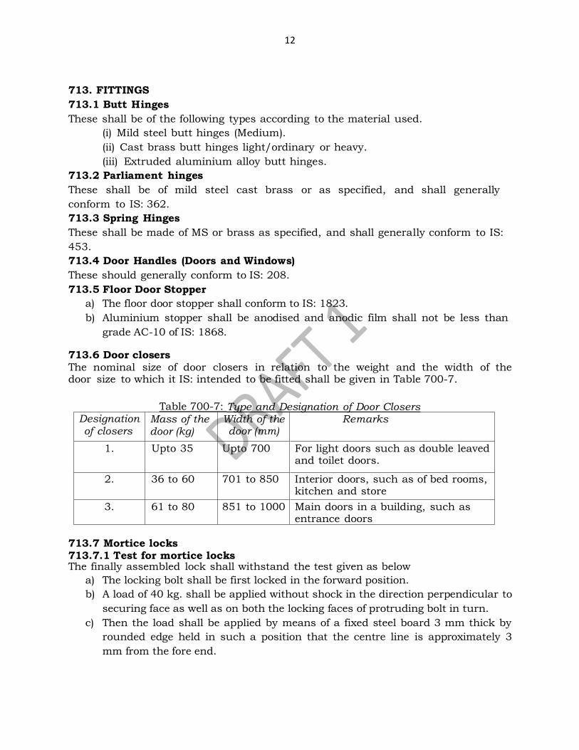
713.6 Door closers The nominal size of door closers in relation to the weight and the width of the door size to which it IS: intended to be fitted shall be given in Table 700-7.
Table 700-7: Type and Designation of Door Closers
Designation of closers
Mass of the door (kg)
Width of the door (mm)
Remarks
1. Upto 35 Upto 700 For light doors such as double leaved and toilet doors.
2. 36 to 60 701 to 850 Interior doors, such as of bed rooms, kitchen and store
3. 61 to 80 851 to 1000 Main doors in a building, such as entrance doors
713.7 Mortice locks 713.7.1 Test for mortice locks The finally assembled lock shall withstand the test given as below
a) The locking bolt shall be first locked in the forward position.
b) A load of 40 kg. shall be applied without shock in the direction perpendicular to
securing face as well as on both the locking faces of protruding bolt in turn.
c) Then the load shall be applied by means of a fixed steel board 3 mm thick by
rounded edge held in such a position that the centre line is approximately 3
mm from the fore end.
13
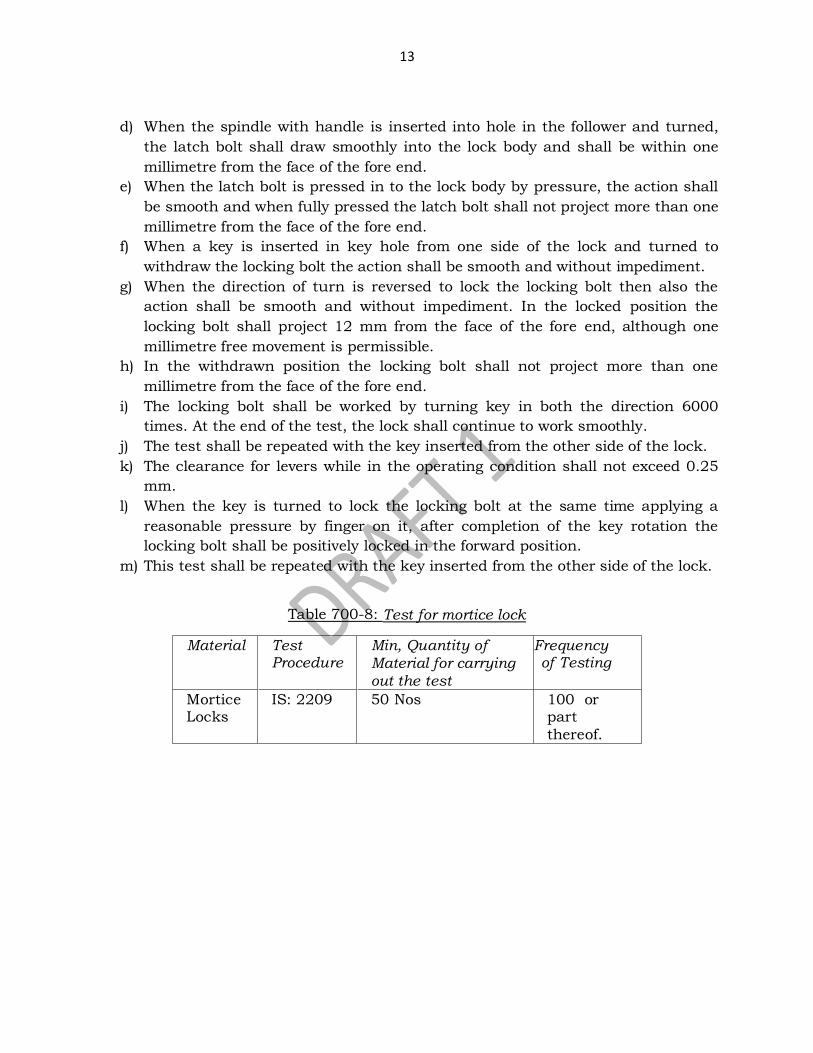
d) When the spindle with handle is inserted into hole in the follower and turned,
the latch bolt shall draw smoothly into the lock body and shall be within one
millimetre from the face of the fore end.
e) When the latch bolt is pressed in to the lock body by pressure, the action shall
be smooth and when fully pressed the latch bolt shall not project more than one
millimetre from the face of the fore end.
f) When a key is inserted in key hole from one side of the lock and turned to
withdraw the locking bolt the action shall be smooth and without impediment.
g) When the direction of turn is reversed to lock the locking bolt then also the
action shall be smooth and without impediment. In the locked position the
locking bolt shall project 12 mm from the face of the fore end, although one
millimetre free movement is permissible.
h) In the withdrawn position the locking bolt shall not project more than one
millimetre from the face of the fore end.
i) The locking bolt shall be worked by turning key in both the direction 6000
times. At the end of the test, the lock shall continue to work smoothly.
j) The test shall be repeated with the key inserted from the other side of the lock.
k) The clearance for levers while in the operating condition shall not exceed 0.25
mm.
l) When the key is turned to lock the locking bolt at the same time applying a
reasonable pressure by finger on it, after completion of the key rotation the
locking bolt shall be positively locked in the forward position.
m) This test shall be repeated with the key inserted from the other side of the lock.
Table 700-8: Test for mortice lock
Material Test Procedure
Min, Quantity of
Material for carrying
out the test
Frequency of Testing
Mortice Locks
IS: 2209
50 Nos 100 or part
thereof.
14
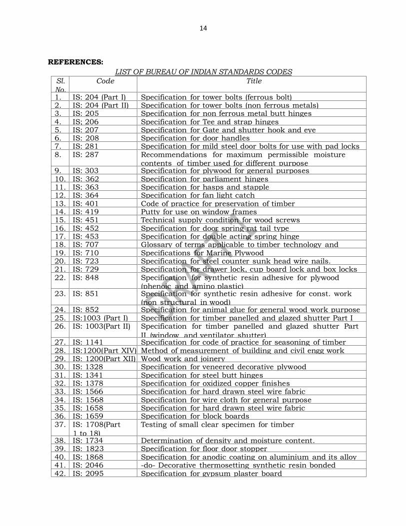
REFERENCES:
LIST OF BUREAU OF INDIAN STANDARDS CODES
Sl.
No.
Code Title
1. IS: 204 (Part I) Specification for tower bolts (ferrous bolt) 2. IS: 204 (Part II) Specification for tower bolts (non ferrous metals) 3. IS: 205 Specification for non ferrous metal butt hinges 4. IS; 206 Specification for Tee and strap hinges 5. IS: 207 Specification for Gate and shutter hook and eye 6. IS: 208 Specification for door handles 7. IS: 281 Specification for mild steel door bolts for use with pad locks 8. IS: 287 Recommendations for maximum permissible moisture
contents of timber used for different purpose 9. IS: 303 Specification for plywood for general purposes 10. IS: 362 Specification for parliament hinges 11. IS: 363 Specification for hasps and stapple 12. IS: 364 Specification for fan light catch 13. IS: 401 Code of practice for preservation of timber 14. IS: 419 Putty for use on window frames 15. IS: 451 Technical supply condition for wood screws 16. IS: 452 Specification for door spring rat tail type 17. IS: 453 Specification for double acting spring hinge 18. IS: 707 Glossary of terms applicable to timber technology and
utilization 19. IS: 710 Specifications for Marine Plywood 20. IS: 723 Specification for steel counter sunk head wire nails. 21. IS: 729 Specification for drawer lock, cup board lock and box locks 22. IS: 848 Specification for synthetic resin adhesive for plywood
(phenoic and amino plastic) 23. IS: 851 Specification for synthetic resin adhesive for const. work
(non structural in wood) 24. IS: 852 Specification for animal glue for general wood work purpose 25. IS:1003 (Part I) Specification for timber panelled and glazed shutter Part I
(door shutters) 26. IS: 1003(Part II) Specification for timber panelled and glazed shutter Part
II (window and ventilator shutter) 27. IS: 1141 Specification for code of practice for seasoning of timber 28. IS:1200(Part XIV) Method of measurement of building and civil engg work
glazing. 29. IS: 1200(Part XII) Wood work and joinery 30. IS: 1328 Specification for veneered decorative plywood 31. IS: 1341 Specification for steel butt hinges 32. IS: 1378 Specification for oxidized copper finishes 33. IS: 1566 Specification for hard drawn steel wire fabric 34. IS: 1568 Specification for wire cloth for general purpose 35. IS: 1658 Specification for hard drawn steel wire fabric 36. IS: 1659 Specification for block boards 37. IS: 1708(Part
1 to 18)
Testing of small clear specimen for timber
38. IS: 1734 Determination of density and moisture content. 39. IS: 1823 Specification for floor door stopper 40. IS: 1868 Specification for anodic coating on aluminium and its alloy 41. IS: 2046 -do- Decorative thermosetting synthetic resin bonded
laminated sheet 42. IS: 2095 Specification for gypsum plaster board
15
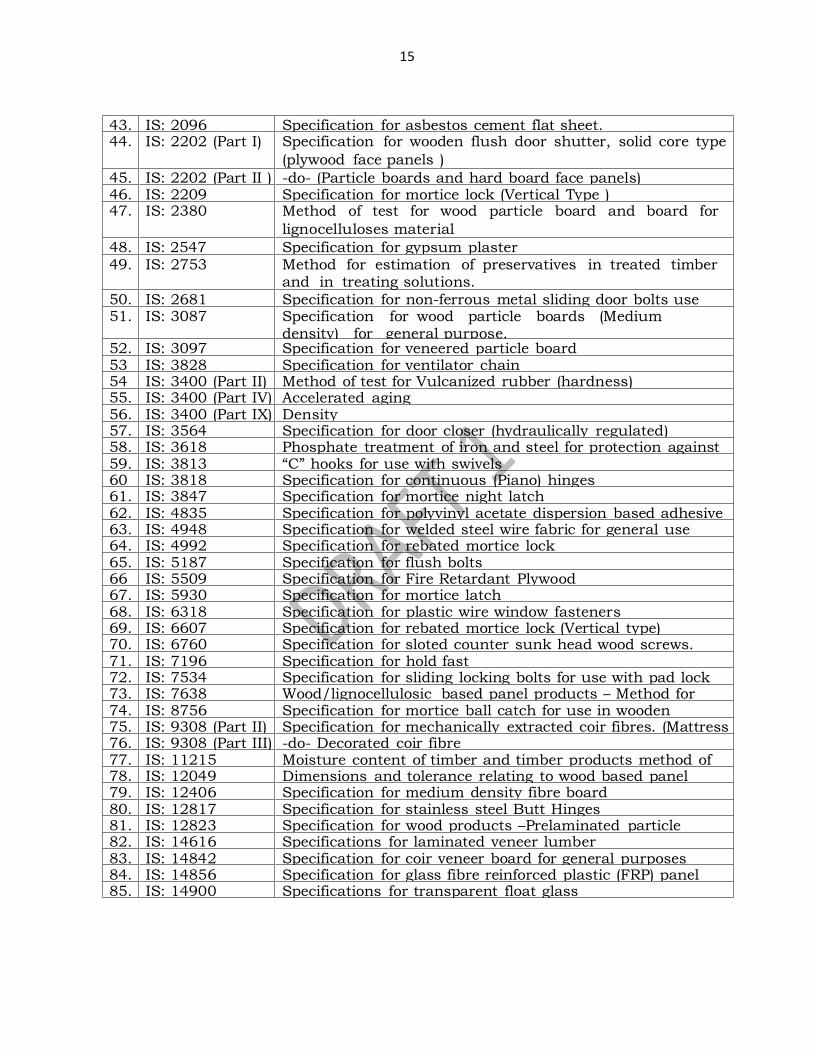
43. IS: 2096 Specification for asbestos cement flat sheet. 44. IS: 2202 (Part I) Specification for wooden flush door shutter, solid core type
(plywood face panels )
45. IS: 2202 (Part II ) -do- (Particle boards and hard board face panels) 46. IS: 2209 Specification for mortice lock (Vertical Type ) 47. IS: 2380 Method of test for wood particle board and board for
lignocelluloses material
48. IS: 2547 Specification for gypsum plaster 49. IS: 2753 Method for estimation of preservatives in treated timber
and in treating solutions.
50. IS: 2681 Specification for non-ferrous metal sliding door bolts use with pad locks 51. IS: 3087 Specification for wood particle boards (Medium density) for general purpose.
52. IS: 3097 Specification for veneered particle board 53 IS: 3828 Specification for ventilator chain 54 IS: 3400 (Part II) Method of test for Vulcanized rubber (hardness) 55. IS: 3400 (Part IV) Accelerated aging 56. IS: 3400 (Part IX) Density 57. IS: 3564 Specification for door closer (hydraulically regulated) 58. IS: 3618 Phosphate treatment of iron and steel for protection against
corrosion 59. IS: 3813 “C” hooks for use with swivels 60 IS: 3818 Specification for continuous (Piano) hinges 61. IS: 3847 Specification for mortice night latch 62. IS: 4835 Specification for polyvinyl acetate dispersion based adhesive
for wood 63. IS: 4948 Specification for welded steel wire fabric for general use 64. IS: 4992 Specification for rebated mortice lock 65. IS: 5187 Specification for flush bolts 66 IS: 5509 Specification for Fire Retardant Plywood 67. IS: 5930 Specification for mortice latch 68. IS: 6318 Specification for plastic wire window fasteners 69. IS: 6607 Specification for rebated mortice lock (Vertical type) 70. IS: 6760 Specification for sloted counter sunk head wood screws. 71. IS: 7196 Specification for hold fast 72. IS: 7534 Specification for sliding locking bolts for use with pad lock 73. IS: 7638 Wood/lignocellulosic based panel products – Method for
sampling 74. IS: 8756 Specification for mortice ball catch for use in wooden almirah 75. IS: 9308 (Part II) Specification for mechanically extracted coir fibres. (Mattress coir fibres) 76. IS: 9308 (Part III) -do- Decorated coir fibre
77. IS: 11215 Moisture content of timber and timber products method of determination 78. IS: 12049 Dimensions and tolerance relating to wood based panel materials 79. IS: 12406 Specification for medium density fibre board
80. IS: 12817 Specification for stainless steel Butt Hinges 81. IS: 12823 Specification for wood products –Prelaminated particle
Boards 82. IS: 14616 Specifications for laminated veneer lumber 83. IS: 14842 Specification for coir veneer board for general purposes 84. IS: 14856 Specification for glass fibre reinforced plastic (FRP) panel
type door 85. IS: 14900 Specifications for transparent float glass
Confidential - For private circulation only
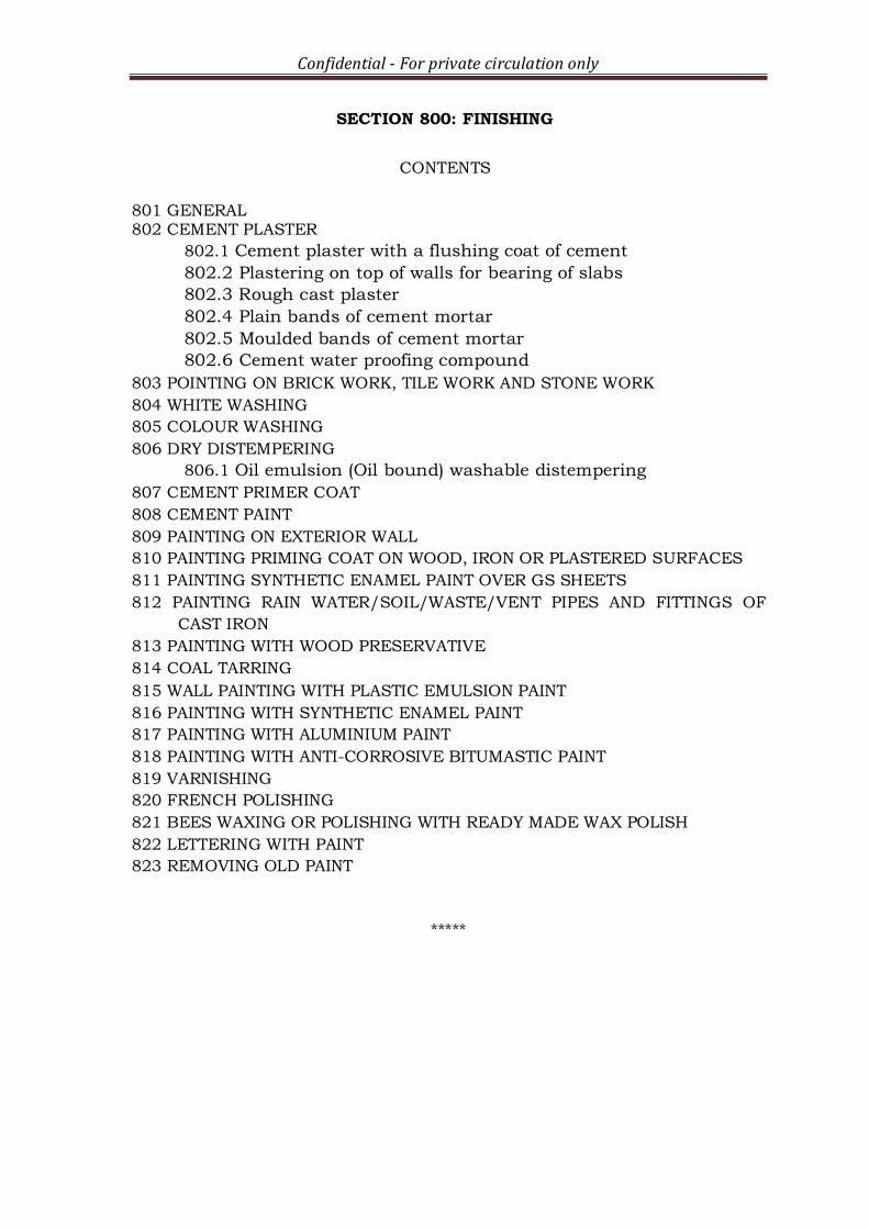
SECTION 800: FINISHING
CONTENTS
801 GENERAL 802 CEMENT PLASTER
802.1 Cement plaster with a flushing coat of cement
802.2 Plastering on top of walls for bearing of slabs
802.3 Rough cast plaster
802.4 Plain bands of cement mortar
802.5 Moulded bands of cement mortar
802.6 Cement water proofing compound
803 POINTING ON BRICK WORK, TILE WORK AND STONE WORK
804 WHITE WASHING
805 COLOUR WASHING
806 DRY DISTEMPERING
806.1 Oil emulsion (Oil bound) washable distempering
807 CEMENT PRIMER COAT
808 CEMENT PAINT
809 PAINTING ON EXTERIOR WALL
810 PAINTING PRIMING COAT ON WOOD, IRON OR PLASTERED SURFACES
811 PAINTING SYNTHETIC ENAMEL PAINT OVER GS SHEETS
812 PAINTING RAIN WATER/SOIL/WASTE/VENT PIPES AND FITTINGS OF
CAST IRON
813 PAINTING WITH WOOD PRESERVATIVE
814 COAL TARRING
815 WALL PAINTING WITH PLASTIC EMULSION PAINT
816 PAINTING WITH SYNTHETIC ENAMEL PAINT
817 PAINTING WITH ALUMINIUM PAINT
818 PAINTING WITH ANTI-CORROSIVE BITUMASTIC PAINT
819 VARNISHING
820 FRENCH POLISHING
821 BEES WAXING OR POLISHING WITH READY MADE WAX POLISH
822 LETTERING WITH PAINT
823 REMOVING OLD PAINT
*****
1
SECTION 800: FINISHING
801 GENERAL
Finishing of a building includes finishing works of floor, wall, ceiling etc.
Several types of finishes can be provided based on the materials used,
environmental conditions and cost.
802 CEMENT PLASTER
a) The cement plaster shall be 9 mm, 12 mm, 15 mm or as specified in the
item.
b) Ceiling plaster shall be completed before commencement of wall plaster. All
corners, arrises, angles and junctions shall be truly vertical or horizontal
as the case may be and shall be carefully finished.
c) Rounding or chamfering corners, arrises, provision of grooves at junctions
etc. where required shall be done without any extra payment. Such
rounding, chamfering or grooving shall be carried out with proper
templates or battens to the sizes required.
d) No portion of the surface shall be left out initially to be patched up later
on.
e) The plastering and finishing shall be completed within half an hour of
adding water to the dry mortar.
f) The plaster shall be finished to a true and plumb surface and to the proper
degree of smoothness as required.
g) The work shall be tested frequently as the work proceeds with a true
straight edge not less than 2.5 m long and with plumb bobs.
h) All horizontal lines and surfaces shall be tested with a level and all jambs
and corners with a plumb bob as the work proceeds.
i) Curing shall be started as soon as the plaster has hardened sufficiently
not to be damaged when watered.
j) The plaster shall be kept wet for a period of at least 7 days. The dates on
which the plastering is done shall be legibly marked on the various
sections plastered so that curing for the specified period thereafter can be
watched.
k) Any cracks which appear in the surface and all portions which sound
hollow when tapped, or are found to be soft or otherwise defective, shall
be cut out in rectangular shape and redone as directed by the Field
Engineers.
802.1 Cement plaster with a flushing coat of cement
a) The cement plaster shall be 12 or 15 mm thick, finished with a
flushing coat of cement or as specified in the item.
b) All relevant points for ensuring quality control for cement plaster are
applicable to this type of finishing also.
802.2 Plastering on top of walls for bearing of slabs
a) Cement plaster shall be 6 mm thick finished with a floating coat of neat
cement on top of walls for bearing of slabs.
2
b) A layer of Tar felt paper of suitable thickness shall be placed over the
plastered surface before the slab is cast.
c) All relevant points for ensuring quality control for cement plaster are
applicable to this type of finishing also.
802.3 Rough cast plaster
a) Rough cast finish comprises of a mixture of sand and gravel in specified
proportions dashed over a freshly plastered surface.
b) It shall be ensured that the base surface which is to receive rough cast
mixture is in plastic state.
c) The rough cast mixture shall consist of sand or gravel or crushed stone
of uniform colour from 2.36 mm to 12.5 mm size or as specified and in
the proportions as specified accurately to the effect required.
d) The mixture shall be wetted and shall be dashed on the plaster base in
plastic state by hand scoop so that the mix gets well pitched into the
plaster base.
e) The mix shall again be dashed over the vacant spaces, if any, so that the
surface represents homogeneous surfaces of sand mixed with gravel.
f) A sample of rough cast plaster shall be got approved by the Field
Engineers.
g) All relevant points for ensuring quality control for cement plaster are
applicable to this type of finishing also.
802.4 Plain bands of cement mortar
a) Plain band is a plaster strip of uniform width not exceeding 30 cm and
of uniform thickness, provided for decorative or other purpose flush with,
sunk below or projecting beyond, the wall plaster.
b) A flush band is one where due to the difference in mix or shade of the
mortar, the band is executed as a separate and distinct operation from the
wall plaster.
c) The horizontal or vertical lines of bands shall be truly parallel and
straight and the surfaces shall be finished truly plane and smooth.
d) The lines and surfaces shall be checked with fine threads for straightness,
level and accuracy.
802.5 Moulded bands of cement mortar
a) Moulded band is a plaster strip of uniform width but with varying
thickness across its section formed over wall plaster for decorative
purposes. The sectional periphery of the band is formed by a
combination of straight lines or of curves or of straight lines and curves.
b) Proper templates conforming to the sectional periphery of the moulded
band as at the stages of the under coat and the finished final coat shall be
made and got approved and used at the proper stages in executing the
bands to true and accurate profile.
c) The lines of the bands as finally completed shall be truly parallel and straight
and the surfaces smoothly finished.
802.6 Cement water proofing compound
a) It shall be used for cement mortar for plastering.
b) Integral cement water proofing compound conforming to IS: 2645 and of

3
approved brand and manufacture, enlisted by the Field Engineers shall be
used.
c) The contractor shall bring the materials to the site in their original packing.
d) The containers will be opened and the material mixed with dry cement in
the proportion by weight, recommended by the manufacturers or as
specifically described in the description of the item.
e) Care shall be taken in mixing, to see that the water proofing material gets
well and integrally mixed with the cement and does not run out separately
when water is added.
803 POINTING ON BRICK WORK, TILE WORK AND STONE WORK
a) The mortar shall be pressed into the raked out joints, with a pointing
trowel, either flush, sunk or raised, according to the type of pointing
required.
b) The mortar shall not spread over the corner, edges or surface of the
masonry.
c) The pointing shall then be finished with the proper tool.
d) The pointing lines shall be truly horizontal and vertical except where the
joints are slanting as in random rubble masonry.
e) Lines of joints from different directions should meet neatly at the
junctions instead of crossing beyond.
f) The pointing shall be kept wet for seven days. During this period it shall be
suitably protected from all damages.
804 WHITE WASHING
a) White washing shall be done using lime or similar products available in the
market as specified in the item.
b) The white wash shall be applied with brushes of specified standards to the
specified number of coats.
c) The operation for each coat shall consist of a stroke of the brush given
from the top downwards, another from the bottom upwards over the
first stroke, and similarly one stroke horizontally from the right and
another from the left before it dries.
d) Each coat shall be allowed to dry before the next one is applied.
e) No portion of the surface shall be left out initially to be patched up later
on.
f) For new work, two coats shall be applied till the surface presents a
smooth and uniform finish through which the plaster does not show.
g) The finished dry surface shall not show any signs of cracking and
peeling nor shall it come off readily on the hand when rubbed.
h) The white washed surface should present a uniform finish through which
the plaster patches do not appear.
i) The washing on ceiling should be done prior to that on walls.
j) Doors, windows, floors, articles of furniture etc. and such other parts of
the building not to be white washed, shall be protected from being splashed
upon. Splashings and droppings, if any shall be removed and the surfaces
cleaned.
4
805 COLOUR WASHING
a) The mineral colours not affected by lime, shall be added to white wash.
b) No colour wash shall be done until a sample of the colour wash of the
required tint or shade has been got approved from the Field Engineer.
c) The colour shall be of even tint or shade over the whole surface.
d) If it is blotchy or otherwise badly applied, it shall be redone.
e) The finished dry surface shall not be powdery and shall not readily come off
on the hand when rubbed.
f) All relevant points for ensuring quality control for white washing are
applicable to this type of finishing also.
806 DRY DISTEMPERING
a) Dry distemper of required colour (IS: 427) and of approved brand and
manufacture shall be used.
b) The shade shall be got approved by the Field Engineer before
application of the distemper.
c) The dry distemper colour as required shall be stirred slowly in clean
water using 6 decilitres (0.6 litre) of water per kg of distemper or as
specified by the makers.
d) Warm water shall preferably be used.
e) It shall be allowed to stand for at least 30 minutes (or if practicable over
night) before use.
f) The mixture shall be well stirred before and during use to maintain an
even consistency.
g) Distemper shall not be mixed in larger quantity than is actually required
for one day’s work.
806.1 Oil emulsion (Oil bound) washable distempering
a) Oil emulsion (Oil bound) washable distemper (IS: 428) of approved brand
and manufacture shall be used.
b) The primer used in new work shall be cement primer or distemper primer as
specified in the item.
c) These shall be of the same manufacture as distemper.
d) The distemper shall be diluted with water or any other prescribed
thinner in a manner recommended by the manufacturer.
e) Only sufficient quantity of distemper required for day’s work shall be
prepared.
f) The distemper and primer shall be brought by the contractor in sealed
tins in sufficient quantities.
g) Oil bound distemper is not recommended to be applied, within six
months of the completion of wall plaster. However, newly plastered
surfaces if required to be distempered before a period of six months shall
be given a coat of alkali resistant priming Paint conforming to IS: 109
and allowed to dry for at least 48 hours before distempering is
commenced.
h) For old work, no primer coat is necessary.
5
807 CEMENT PRIMER COAT
a) Cement primer coat is used as a base coat on wall finish of cement, lime
or lime cement plaster or on non-asbestos cement surfaces before oil
emulsion distemper paints are applied on them.
b) Primer coat shall be preferably applied by brushing and not by
spraying.
c) Hurried priming shall be avoided particularly on absorbent surfaces.
d) New plaster patches in old work should also be treated with cement primer
before applying oil emulsion Paints etc.
808 CEMENT PAINT
a) The cement paint shall be of approved brand and manufacture conforming
to IS: 5410.
b) The cement paint shall be brought to the site of work in its original
containers is sealed condition.
c) The materials shall be brought in at a time in adequate quantities to suffice
for the whole work.
d) The lids of cement paint drums shall be kept tightly closed when not in
use, as by exposure to atmosphere the cement paint rapidly becomes air
set due to its hygroscopic qualities.
e) In case of cement paint brought in gunny bags, once the bag is opened, the
contents should be consumed in full on the day of its opening. If the same
is not likely to be consumed in full, the balance quantity should be
transferred and preserved in an airtight container to avoid its exposure to
atmosphere.
f) Water proof cement p aint shall not be applied on surfaces already
treated with white wash, colour wash, distemper dry or oil bound,
varnishes, p aints etc.
g) It shall not be applied on gypsums, wood and metal surfaces.
h) If water proofing cement is required to be applied on existing surface,
previously treated with white wash, colour wash etc., the surface shall
be thoroughly cleaned by scrapping off all the white wash, colour wash
etc. completely.
i) Thereafter, a coat of cement primer shall be applied followed by two
coats of water proof cement.
809 PAINTING ON EXTERIOR WALL
a) Before pouring into smaller containers for use, the paint shall be stirred
thoroughly in its container, when applying also the paint shall be
continuously stirred in the smaller containers so that its consistency is
kept uniform.
b) Dilution ratio of paint with potable water can be altered taking into
consideration the nature of surface, climate and as per recommended
dilution given by manufacturer.
c) In all cases, the manufacturer’s instructions & directions of the Field
Engineer shall be followed meticulously.
6
d) The lids of paint drums shall be kept tightly closed when not in use as
by exposure to atmosphere the paint may thicken and also be kept safe
from dust.
810 PAINTING PRIMING COAT ON WOOD, IRON OR PLASTERED SURFACES
a) The primer for wood work, iron work or plastered surface shall be as
specified in the description of item.
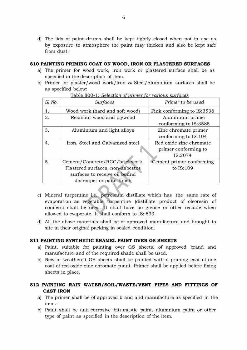
b) Primer for plaster/wood work/Iron & Steel/Aluminium surfaces shall be
as specified below:
Table 800-1: Selection of primer for various surfaces
Sl.No. Surfaces Primer to be used
1. Wood work (hard and soft wood) Pink conforming to IS:3536
2. Resinour wood and plywood Aluminium primer
conforming to IS:3585
3. Aluminium and light alloys Zinc chromate primer
conforming to IS:104
4. Iron, Steel and Galvanized steel Red oxide zinc chromate
primer conforming to
IS:2074
5. Cement/Concrete/RCC/brickwork,
Plastered surfaces, non-asbestos
surfaces to receive oil bound
distemper or paint finish
Cement primer conforming
to IS:109
c) Mineral turpentine i.e. petroleum distillate which has the same rate of
evaporation as vegetable turpentine (distillate product of oleoresin of
conifers) shall be used. It shall have no grease or other residue when
allowed to evaporate. It shall conform to IS: 533.
d) All the above materials shall be of approved manufacture and brought to
site in their original packing in sealed condition.
811 PAINTING SYNTHETIC ENAMEL PAINT OVER GS SHEETS
a) Paint, suitable for painting over GS sheets, of approved brand and
manufacture and of the required shade shall be used.
b) New or weathered GS sheets shall be painted with a priming coat of one
coat of red oxide zinc chromate paint. Primer shall be applied before fixing
sheets in place.
812 PAINTING RAIN WATER/SOIL/WASTE/VENT PIPES AND FITTINGS OF
CAST IRON
a) The primer shall be of approved brand and manufacture as specified in the
item.
b) Paint shall be anti-corrosive bitumastic paint, aluminium paint or other
type of paint as specified in the description of the item.
7
813 PAINTING WITH WOOD PRESERVATIVE
a) Oil type wood preservative of specified quality and approved make,
conforming to IS: 218 shall be used.
b) Generally, it shall be creosote oil Type-I or anthracene oil.
814 COAL TARRING
a) Coal tar of approved manufacture conforming to IS: 290 shall be used.
b) The tar, to every litre of which 200 gm of un-slaked lime has been
added, shall be heated till it begins to boil.
c) It must then be taken off the fire and kerosene oil added to it slowly at
the rate of one part of kerosene oil to six or more parts by volume and
stirred thoroughly.
d) The addition of lime is for preventing the tar from running.
815 WALL PAINTING WITH PLASTIC EMULSION PAINT
a) Plastic Emulsion Paint shall confirm to IS: 5411 and shall be of the
approved brand and manufacture.
b) The plastic emulsion paint is not suitable for application on external, wood
and iron surface and surfaces which are liable to heavy condensation.
c) These paints are to be used on internal surfaces except wooden and
steel.
d) Plastic emulsion paint specially made for exterior surfaces shall be used
for painting exterior surfaces.
e) The shade shall be got approved from the Engineer before application of
the distemper.
f) Each coat shall be allowed to dry before the next one is applied.
g) Painting of external surface should not be done in adverse weather
condition like hail storm and dust storm.
h) No portion of the surface shall be left out initially to be patched up later
on.
i) The painting on ceiling should be done prior to that on walls.
j) Doors, windows, floors, articles of furniture etc. and such other parts of
the building shall be protected from being splashed upon. Splashings and
droppings, if any shall be removed and the surfaces cleaned.
k) Plastic emulsion p aint shall not be applied on surfaces already treated
with white wash, colour wash, distemper dry or oil bound, varnishes,
paints etc.
l) If plastic emulsion paint is required to be applied on existing surface,
previously treated with white wash, colour wash etc., the surface shall
be thoroughly cleaned by scrapping off all the white wash, colour wash
etc. completely. Thereafter, a coat of cement primer shall be applied
followed by two coats of plastic emulsion paint.
m) It shall not be applied on wood and metal surfaces.
n) In all cases, the manufacturer’s instructions & directions of the Engineer
shall be followed meticulously.
o) The paint shall be brought to the site of work in its original containers
8
in sealed condition.
p) The materials shall be brought in at a time in adequate quantities to suffice
for the whole work.
q) The lids of paint drums shall be kept tightly closed when not in use as
by exposure to atmosphere the paint may thicken.
r) It shall also be kept safe from dust.
816 PAINTING WITH SYNTHETIC ENAMEL PAINT
a) Synthetic Enamel Paint of approved brand and manufacture conforming to
IS: 2933 and of the required colour shall be used.
b) At the time of delivery the paint shall be in such a condition that manual
stirring readily produces a uniform product.
c) During the twelve months storage period, the rating for degree of settling
shall not drop to zero, when tested as per IS: 101 (Part 6/Section 2).
d) The paint shall be free from coarse particles, suspended particles of gel
and foreign matter, when tested as per IS: 101 (Part 1/Section 2).
e) The paint shall show no skin formation, when examined visually at the
time of delivery.
f) The paint shall be capable of being readily mixed with the petroleum
hydrocarbon, solvent grade (IS: 1745) or with a suitable thinner as agreed
to between the purchaser and the supplier, without showing any
precipitation.
g) The material shall be supplied in brushing consistency, suitable for
application by brushing and air spraying.
817 PAINTING WITH ALUMINIUM PAINT
a) Aluminium paint shall be of approved brand and manufacture
conforming to IS: 2339.
b) If the paint comes in compact dual container with the paste and the
medium separately, the two shall be mixed together to proper consistency
before use.
c) As aluminium paste is likely to settle in the container, care shall be taken
to frequently stir the paint during use.
d) Also the paint shall be applied and laid off quickly, as surface is
otherwise not easily finished.
818 PAINTING WITH ANTI-CORROSIVE BITUMASTIC PAINT
a) Ready mixed paint shall be of approved brand and manufacture
conforming to IS: 158.
b) It shall be black, lead free, acid-alkali-heat-water resistant.
819 VARNISHING
a) Varnish for the finishing and undercoats shall be of the approved
manufacturer conforming to IS: 347.
b) Ordinary copal varnish or superior quality spray varnish shall be used.
c) The work includes sizing of transparent wood filler.
9
d) Rubbing down and flatting the surface shall be done after each coat
except the final coat with fine sand paper.
e) The work shall be allowed to dry away from droughts and damp air. The
finished surface shall then present a uniform appearance and fine glossy
surface free from streaks, blister etc.
f) Any varnish left over in the small container shall not be poured back
into the stock tin, as it will render the latter unfit for use.
g) Special fine haired varnishing brushes shall be used and not ordinary
paint brushes. Brushes shall be well worn and perfectly clean.
820 FRENCH POLISHING
Readymade polish conforming to IS: 348 shall be used
821 BEES WAXING OR POLISHING WITH READY MADE WAX POLISH
The polishing shall be done with readymade wax polish of approved brand and
manufacture.
822 LETTERING WITH PAINT
Black Japan paint conforming to IS: 341 or ready mixed paint as approved by the
Engineer shall be used.
823 REMOVING OLD PAINT
a) With Patent Paint Remover - Patent Paint removers shall consist of volatile
organic liquids thickened with waxes and other ingredients to retard the
evaporation of the liquid and to enable a substantial layer of remover to
be applied to the surface. The Paint remover shall be of a brand and
manufacture approved by the Engineer. It shall be free from alkaline
matter and non-caustic so that it can be handled by workmen without
injury. It shall be of non inflammable quality as far as possible.
b) With Caustic Soda Solution - Caustic soda, as its name implies, is a
corrosive liquid and care should be taken to see that no liquid spills over
the skin or clothing.
c) With Blow Lamp - The paint shall be removed either with a blow lamp or
air-acetylene equipment. The flame shall be allowed to play upon the
paint just enough to soften it without charring either the paint or the
background. The softened paint shall then be removed with a stripping
knife following the flame as it is moved up the surface. Burning off shall
begin at the bottom of the vertical surface and shall proceed upwards.
Removal with blow lamp shall not be done on narrow or carved
undercut surfaces or where there is risk of damage to neighbouring
materials such as panes in glazed windows.
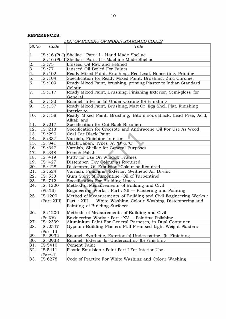
10
REFERENCES:
LIST OF BUREAU OF INDIAN STANDARD CODES
Sl.No.
Code Title
1. IS :16 (Pt-I) Shellac : Part : I - Hand Made Shellac IS :16 (Pt-II) Shellac : Part : II - Machine Made Shellac 2. IS :75 Linseed Oil Raw and Refined 3. IS :77 Linseed Oil Boiled For Paints 4. IS :102 Ready Mixed Paint, Brushing, Red Lead, Nonsetting, Priming 5. IS :104 Specification for Ready Mixed Paint, Brushing, Zinc Chrome,
Priming 6. IS :109 Ready Mixed Paint, brushing, priming Plaster to Indian Standard Colour No.361, 631 White and off White 7. IS :117 Ready Mixed Paint, Brushing, Finishing Exterior, Semi-gloss for General
Purposes to Indian Standards Colours. 8. IS :133 Enamel, Interior (a) Under Coating (b) Finishing 9. IS :137 Ready Mixed Paint, Brushing, Matt Or Egg Shell Flat, Finishing
Interior to Indian Standard Colour as required 10. IS :158 Ready Mixed Paint, Brushing, Bituminous Black, Lead Free, Acid, Alkali and
Heat Resisting 11. IS :217 Specification for Cut Back Bitumen 12. IS: 218 Specification for Creosote and Anthracene Oil For Use As Wood
Preservatives 13. IS :290 Coal Tar Black Paint 14. IS :337 Varnish, Finishing Interior 15. IS: 341 Black Japan, Types ‘A’, ‘B’ & ‘C’ 16. IS :347 Varnish, Shellac for General Purposes 17. IS: 348 French Polish 18. IS: 419 Putty for Use On Window Frames 19. IS: 427 Distemper, Dry Colour as Required 20. IS :428 Distemper, Oil Emulsion, Colour as Required 21. IS :524 Varnish, Finishing, Exterior, Synthetic Air Drying 22. IS: 533 Gum Spirit of Turpentine (Oil of Turpentine) 23. IS: 712 Specification For Building Limes 24. IS: 1200
(Pt-XII)
Method of Measurements of Building and Civil
Engineering Works : Part : XII — Plastering and Pointing
25. IS:1200 (Part-XIII)
Method of Measurements of Building and Civil Engineering Works : Part : XIII — White Washing, Colour Washing Distempering and Painting of Building Surfaces.
26. IS :1200
(Pt-XV)
Methods of Measurements of Building and Civil
Engineering Works : Part : XV — Painting, Polishing,
Varnishing etc. 27. IS: 2339 Aluminium Paint For General Purposes, in Dual Container 28. IS :2547
(Part-II)
Gypsum Building Plasters Pt.II Premixed Light Weight Plasters
29. IS: 2932 Enamel, Synthetic, Exterior (a) Undercoating, (b) Finishing 30. IS: 2933 Enamel, Exterior (a) Undercoating (b) Finishing 31. IS:5410 Cement Paint 32. IS:5411
(Part-1)
Plastic Emulsion : Paint Part I For Interior Use
33. IS:6278 Code of Practice For White Washing and Colour Washing
Confidential - For private circulation only
SECTION 1100: FLOORING
CONTENTS
1101 GENERAL
1102 CEMENT CONCRETE FLOORING
1102.1 Materials
1102.2 Requirements 1102.3 Workmanship
1103 CEMENT PLASTER IN RISERS OF STEPS, SKIRTING, DADO
1103.1 Workmanship
1104 TERRAZO (MARBLE CHIPS) FLOORING LAID IN-SITU
1104.1 Materials
1104.2 Requirements
1104.3 Workmanship
1105 CRAZY MARBLE STONE FLOORING
1106 TERRAZZO TILE FLOORING
1106.1 Materials
1106.2 Workmanship
1106.3. Tolerances
1106.4. Sampling
1107 CHEQUERED TILE FLOORING
1107.1 Requirements
1107.2. Workmanship
1108 ACID OR ALKALI RESISTANT TILES
1108.1 Requirements
1108.2 Workmanship
1108.3 Tolerances
1108.4 Sampling and testing
1109 PRESSED CERAMIC TILE FLOORING
1109.1 General
1109.2 Requirements
1109.3 Workmanship (Flooring)
1109.4 Workmanship (Skirting and Dado)
1109.5 Sampling and testing
1110. TILE FIXING WITH QUICK SET ADHESIVE (WATER BASED)
1110.1 General
1110.2 Materials
1110.3 Workmanship
1111. VITRIFIED TILE FLOORING
1111.1 Materials
1111.2 Requirements
1112. MARBLE STONE FLOORING
1112.1 Materials 1112.2 Requirements
1112.3 Workmanship
1112.4 Tolerances

Confidential - For private circulation only
1113. KOTA STONE FLOORING
1113.1 Materials
1113.2 Requirements
1113.3 Workmanship
1113.4 Tolerances
1114 GRANITE FLOORING
1114.1 Materials
1114.2 Requirements
1114.3 Workmanship
1115. WOODEN FLOORING
1115.1 Materials
1115.2 Requirements
1115.3 Workmanship
*****
1
SECTION 1100: FLOORING
1101 GENERAL
a) The purpose of a floor is to provide a horizontal sanitary surface to support
the occupants of a building, furniture and equipment.
b) Floor finishes depend on the expected load, the desired resistance to
abrasion and wear, speed of execution and the architectural and aesthetic
requirements of a building.
The floor finishes in common use are discussed in this section.
1102 CEMENT CONCRETE FLOORING
1102.1 Materials
Cement concrete of specified mix grade shall be used and it shall conform to the
requirements given under relevant section for concrete.
1102.2 Requirements
a) Base concrete, if provided shall be with the slopes required for the flooring.
Flooring in verandah, courtyard, kitchen & bath shall have slope ranging
from 1:48 to 1:60 depending upon location.
b) Floors in water closet (WC) portion shall have slope of 1:30 to drain off
washing water. Further, necessary drop in flooring in bath, WC, kitchen
near floor traps ranging from 6 mm to 10 mm will also be provided to avoid
spreading of water. Necessary margin to accommodate this drop shall be
made in the base concrete. Plinth masonry off set shall be depressed so as to
allow the base concrete to rest on it.
c) Flooring shall commence preferably within 48 hours of the laying of base
concrete. Immediately before laying the flooring, the base shall be wetted
and a coat of cement slurry @ 2 kg per m2 area spread to get a good bond
between the base and concrete floor.
d) If the cement concrete flooring is to be laid directly on an RCC slab, the top
surface of RCC slab shall be cleaned and the laitance shall be removed and a
coat of cement slurry shall be applied as mentioned in (c). 1102.3 Workmanship
a) The thickness of floor shall be as specified in the item.
b) Laying in panels - The border panels shall not exceed 450 mm in width and
the joints in the border shall be in line with panel joints. The panels shall be
of uniform size and no dimension of a panel shall exceed 2 m and the area of
a panel shall not be more than 2 m2. The joints of borders at corners shall
be mitred for provision of strips.
c) Laying of flooring with strips - Normally cement concrete flooring shall be laid
in one operation using glass/aluminium/PVC/brass strips/stainless steel
strips or any other strips as required at the junction of two panels. This
method ensures uniformity in colour of all the panels and straightness at the
junction of the panels. 4 mm thick glass strips or 2 mm PVC strips or 2 mm
aluminium or brass strips shall be fixed with their tops at proper level,
giving required slope. Use of glass and metallic strips shall be avoided in
areas exposed to sun.
d) Concreting - Cement concrete shall be placed in the panels and be levelled
with the help of straight edge and trowel. It shall be properly compacted by
2
suitable means. The evenness of the surface shall be checked with straight
edge. Surface of flooring shall be true to the required slope. While laying
concrete, care shall be taken to see that the strips are not
damaged/disturbed. The top of strips shall be visible clearly after finishing
with cement slurry. Laying of cement concrete flooring in alternate panels
may be allowed in case strips are not to be provided.
e) Finishing - The finishing of the surface shall follow immediately after
compaction. The surface shall be left untouched till moisture disappears
from it. Use of dry cement or cement-sand mixture to absorb excessive
moisture shall not be permitted. Excessive trowelling shall be avoided. The
men engaged on finishing operations shall be provided with raised wooden
platform to sit on so as to prevent damage to new work.
f) Curing - The curing shall be done for a minimum period of ten days.
Covering with empty cement bags shall be avoided as the colour of the
flooring is likely to be bleached due to the presence of cement dust from the
bags. g) For cement concrete pavement in courtyard and terrace etc., the panels shall
be of uniform size and no dimension of a panel shall exceed 1.25 m and the area of panel should not exceed 1.25 m2 for the thickness of panels up to 50 mm. Concreting shall be done in alternate panels only and no glass/asbestos strips shall be provided.
1103 CEMENT PLASTER IN RISERS OF STEPS, SKIRTING, DADO 1103.1 Workmanship
a) Plaster at the bottom of wall not exceeding 30 cm in height above the floor
shall be classified as skirting.
b) The work shall be preferably carried out simultaneously with the laying of
floor. The corners and junctions with floor shall be finished neatly as
specified.
c) The joints shall be raked out to a depth of at least 15 mm in masonry walls.
In case of concrete walls, the surfaces shall be roughened properly. The
surface shall be cleaned thoroughly, washed with water and kept wet before
skirting is commenced.
d) Skirting with specified mortar and to specified thickness shall be laid
immediately after the surface is prepared.
e) It shall be laid and finished along with the border or adjacent panels of floor.
The joints in skirting shall be kept true and straight in continuation of the
line of joints in borders or adjacent panels.
f) The skirting shall be finished smooth with top truly horizontal and joints
truly vertical except where otherwise indicated.
g) The cement to be applied in the form of slurry for smooth finishing shall be
at the rate of 2 kg of cement per litre of water applied over an area of 1 m2.
h) Where skirting is flush with plaster, a groove 10 mm wide and up to 5 mm
depth shall be provided in plaster at the junction of skirting with plaster. i) Curing shall be commenced when the plaster has hardened sufficiently but
not later than 16 hours after finishing and shall be continued for a minimum period of 7 days.
3
1104 TERRAZO (MARBLE CHIPS) FLOORING LAID IN-SITU
1104.1 Materials
a) The marble chips shall be of quality and colour as specified.
b) It shall be hard, sound, dense and homogenous in texture with crystalline
and coarse grains.
c) It shall be uniform in colour and free from stains, cracks, decay and
weathering.
d) The mix for terrazo shall consist of cement with or without pigment, marble
powder, marble aggregate (marble chips) and water.
1104.2 Requirements
a) The maximum thickness of the top layer for various sizes of marble
aggregates (marble chips) shall be 6 mm to 12 mm depending on the
aggregate size.
b) Where aggregate of size larger than 10 mm are used, the minimum thickness
of topping shall not be less than one and one third times the maximum size
of the chips.
c) Where large size chips such as 20 mm or 25 mm are used, they shall be
used only with a flat shape and bedded on the flat face so as to keep the
minimum thickness of wearing layer.
1104.3 Workmanship
a) Cement concrete of specified mix shall be used for the base layer.
b) The flooring shall be provided in panels which shall be of uniform size, not
exceeding 2 m2 in area or 2 m in length for inside situations.
c) In exposed situations, the length of any side of the panel shall not be more
than 1.25 metre.
d) Cement slurry @ 2.00 kg per m2 shall be applied before laying of the terrazzo
over the cement concrete/RCC flooring.
e) For providing panels, 4 mm thick glass strips or 2 mm thick PVC strips/
aluminium strips/brass strips/stainless steel strips/copper strips unless
otherwise specified shall be fixed with their top at proper level to required
slope.
f) Strips of stone or marble or of any other material of specified thickness
can also be used if specifically required.
g) Use of glass and metallic strips shall be avoided in areas exposed to sun.
h) Laying and fixing of strips shall be as specified in 1102.
i) The cement and marble powder shall be mixed in the proportion of three
parts of cement to one part marble powder by weight.
j) The cement to be used shall be ordinary grey cement, white cement, cement
with admixture of colouring matter of approved quality in the ratio specified
in the description of the item in the ratio to get the required shade as
directed by the Engineer.
k) Colouring materials where specified shall be mixed dry thoroughly with the
cement and marble powder and then marble chips added and mixed as
specified above.
l) The full quantity of dry mixture of mortar required for a room shall be
prepared in a lot in order to ensure a uniform colour. This mixture shall be
stored in a dry place and well covered and protected from moisture.
4
m) The dry mortar shall be mixed with water in the usual way as and when
required. The mixed mortar shall be homogenous and stiff and contain just
sufficient water to make it workable.
n) The terrazo topping shall be laid after the base layer has hardened
sufficiently to prevent cement from rising to the surface. This is normally
achieved between 18 to 24 hours after the under layer has been laid.
o) The surface of the top layer shall be trowelled over, pressed and brought true
to required level by a straight edge and steel floats in such a manner that
the maximum amount of marble chips come up and are spread uniformly
over the surface.
p) A cement slurry preferably of the same colour as the topping shall be
brushed on the surface laid to a uniform thickness slightly more than that
specified in order to get the specified finished thickness after rubbing.
q) The surface shall be left dry for air-curing for a duration of 12 to 18 hours
depending on atmospheric temperature conditions. It shall then be cured by
allowing water to stand in pools over it for a period of not less than 4 days.
r) The grinding and polishing may be commenced not before 2 days from the
time of completion of laying for manual grinding and not before 7 days for
machine grinding. For polishing by machines, the surface shall be watered
and ground evenly with machine fitted with special rapid cutting grit blocks
(carborandum stone) of coarse grade (No. 60) till the marble chips are evenly
exposed and the floor is smooth.
s) After the first grinding, the surface shall be thoroughly washed to remove all
grinding mud and covered with a grout of cement and colouring matter in
same mix and proportion as the topping in order to fill any pin holes that
appear. The surface shall be allowed to dry for 24 hours and wet cured for 4
days and then rubbed with machine fitted with fine grit blocks (No. 120).
t) Curing shall be done again by ponding of water between panels formed with
fine sand. The surface is cleaned and repaired as before and allowed to cure
again for 3 to 5 days.
u) Finally the third grinding shall be done with machine fitted with mere fine
grade grit blocks (No. 320) to get even and smooth surface without pin holes.
The finished surface should show the marble chips evenly exposed.
v) Where use of machine for polishing is not feasible or possible, rubbing and
polishing shall be done by hand, in the same manner as specified for
machine polishing except that carborandum stone of coarse grade (No. 60)
shall be used for the 1st rubbing, stone of medium grade (No. 80) for second
rubbing and stone of fine grade (No. 120) for final rubbing polishing.
w) After the final polish either by machine or by hand, oxalic acid shall be
dusted over the surface @ 33 gm per m2 area sprinkled with water and
rubbed hard with a pad of woollen rags. The following day, the floor shall be
wiped with a moist rag and dried with a soft cloth and finished clean.
x) Wax polish shall be of approved brand and manufacture and in sealed
containers. It shall be applied in uniform layer to the dry surface of the
floor/skirting. When the layer of the wax is stiffened and surface of floor is
saturated with the polish, polishing shall be resorted with machine fitted
5
with bobs (pad of rags) and shall be done until shades of all chips have
appeared and glossy surface is obtained.
1105 CRAZY MARBLE STONE FLOORING
a) Crazy marble stone flooring shall be laid on cement concrete base.
b) The base concrete shall be provided with slope required for the flooring in
verandahs and courtyards to drain off washing and rain water.
c) The guidelines for base concrete detailed under clause 1102 shall strictly be
adhered to.
d) The crazy marble flooring shall be laid on a cement concrete layer of
thickness 25 mm or as specified over the base concrete.
e) The mix shall normally be 1:2:4 using graded stone aggregate 12 mm
nominal size by volume, unless otherwise specified. It shall conform to the
requirements given under clause 1102.
f) The mix of crazy marble stone flooring shall consist of white cement with or
without pigment, marble powder, marble chips and marble stone pieces and
water.
g) The marble stone pieces shall be hard, sound, dense and homogenous in
texture with crystalline and coarse grains.
h) It shall be uniform in colour and free from stains, cracks, decay and
weathering. The marble stone pieces shall be of approved size. Before
starting the work the contractor shall get the sample of marble stone
approved by the Engineer.
i) For 50 mm thick floor, the thickness of marble pieces will be 25 mm while
for 40 mm thick floor, the thickness will be 15 mm.
j) The white cement and marble powder shall be mixed in proportion of three
parts of cement and one part of marble powder by weight, and the
proportion of marble chips to binder mix by volume shall be 7 parts of
marble chips to 4 parts of binder mix.
k) A coat of cement slurry at the rate of 2 kg of cement per m2 of area shall be
spread and then the marble stone pieces shall be set by hand in such a
manner that the top surface of all the set marble stones shall be true to the
required level and slopes.
l) After fixing the stones, the cement marble chips mixture shall be filled in
between the gaps of laid marble stone pieces. The filled surface then shall be
trowelled over, pressed and brought to the level of the laid marble stone
pieces.
m) Curing and finishing and wax polishing shall be as described in clauses
1104.
1106 TERRAZZO TILE FLOORING 1106.1 Materials
a) Terrazzo tiles shall generally conform to IS: 1237.
b) The size of tiles shall be 250 x 250 x 22 mm, 300 x 300 x 25 mm or as
directed by the Engineer.
c) Half tiles for use with the full tiles shall be such as to make two half tiles
when joined together, match with the dimensions of one full tile.
6
d) The minimum finished thickness of tiles for risers of steps, skirting and dado
shall however be 12 mm.
e) The tiles shall be manufactured in a factory under pressure process
subjected to hydraulic pressure not less than 140 kg/cm2 and shall be
given the initial grinding with machine and grouting of the wearing layer
before delivery to site.
f) The wearing layer shall be free from projections, depressions, cracks, holes,
cavities and other blemishes. The edges of wearing layer may be rounded.
g) The proportion of cement to aggregate in the backing of tiles shall be not
leaner than 1:3 by weight. Where colouring material is used in the wearing
layer, it shall not exceed 10 per cent by weight of cement used in the mix.
h) The finished thickness of the upper layer shall not be less than 5 mm for
size of marble chips ranging from the smallest up to 6 mm and also for the
smallest up to 12 mm and not less than 6 mm for size of marble chips
varying from the smallest up to 20 mm.
1106.2 Workmanship
a) The surface on which the tiles are to be laid shall be cleaned wetted and
mopped.
b) The bedding for tiles shall be with cement mortar 1:4 or of specified mix.
c) The minimum thickness of bedding mortar at any place shall be 10 mm.
d) Bedding mortar shall be spread, tamped and corrected to proper levels.
e) After laying bedding mortar, neat grey cement slurry of honey like
consistency shall be spread over the bedding mortar at the rate of 4.4 kg of
cement per m2.
f) Tiles shall be washed cleaned and shall be fixed into this grout butting one
at another, each tile being gently tapped with a wooden mallet till it is
properly bedded, and is in level and line with the adjoining tiles.
g) The joints shall be kept as thin as possible and in straight lines.
h) The surface shall be checked with a straight edge during laying to obtain a
true surface.
i) After the tiles have been laid surplus cement grout shall be cleaned off.
j) Machine grinding and finishing shall be done as detailed under 1104.
k) For small areas or where circumstances so require, hand grinding/polishing
with hand grinder may be permitted in lieu of machine polishing after laying.
For hand polishing the following carborandum stones, shall be used:
First grinding - coarse grade stone (No. 60)
Second grinding - medium grade (No. 80)
Final grinding - fine grade (No. 120)
l) In all other respects, the process shall be similar as for machine polishing.
m) After the final polish, oxalic acid shall be dusted over the surface at the rate
of 33 gm per square metre sprinkled with water and rubbed hard with a pad
of woollen rags. The following day, the floor shall be wiped with a moist rag
and dried with a soft cloth and finished clean.
n) If any tile is disturbed or damaged, it shall be refitted or replaced, properly
jointed and polished.
o) The finished floor shall not sound hollow when tapped with a wooden mallet.
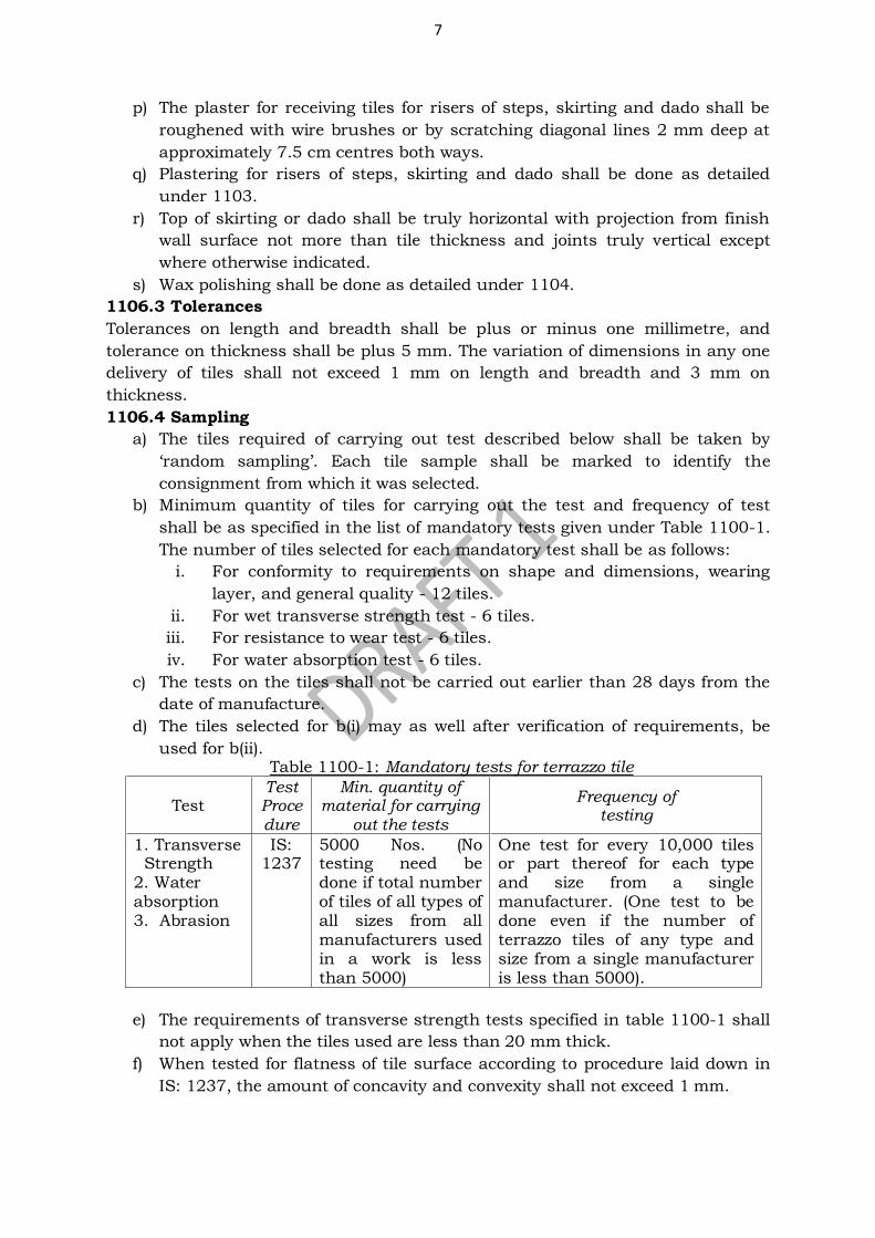
7
p) The plaster for receiving tiles for risers of steps, skirting and dado shall be
roughened with wire brushes or by scratching diagonal lines 2 mm deep at
approximately 7.5 cm centres both ways.
q) Plastering for risers of steps, skirting and dado shall be done as detailed
under 1103.
r) Top of skirting or dado shall be truly horizontal with projection from finish
wall surface not more than tile thickness and joints truly vertical except
where otherwise indicated.
s) Wax polishing shall be done as detailed under 1104.
1106.3 Tolerances
Tolerances on length and breadth shall be plus or minus one millimetre, and
tolerance on thickness shall be plus 5 mm. The variation of dimensions in any one
delivery of tiles shall not exceed 1 mm on length and breadth and 3 mm on
thickness.
1106.4 Sampling
a) The tiles required of carrying out test described below shall be taken by
‘random sampling’. Each tile sample shall be marked to identify the
consignment from which it was selected.
b) Minimum quantity of tiles for carrying out the test and frequency of test
shall be as specified in the list of mandatory tests given under Table 1100-1.
The number of tiles selected for each mandatory test shall be as follows:
i. For conformity to requirements on shape and dimensions, wearing
layer, and general quality - 12 tiles.
ii. For wet transverse strength test - 6 tiles.
iii. For resistance to wear test - 6 tiles.
iv. For water absorption test - 6 tiles.
c) The tests on the tiles shall not be carried out earlier than 28 days from the
date of manufacture.
d) The tiles selected for b(i) may as well after verification of requirements, be
used for b(ii). Table 1100-1: Mandatory tests for terrazzo tile
Test Test Procedure
Min. quantity of material for carrying
out the tests
Frequency of testing
1. Transverse Strength 2. Water absorption 3. Abrasion
IS: 1237
5000 Nos. (No testing need be done if total number of tiles of all types of all sizes from all manufacturers used in a work is less than 5000)
One test for every 10,000 tiles or part thereof for each type and size from a single manufacturer. (One test to be done even if the number of terrazzo tiles of any type and size from a single manufacturer is less than 5000).
e) The requirements of transverse strength tests specified in table 1100-1 shall
not apply when the tiles used are less than 20 mm thick.
f) When tested for flatness of tile surface according to procedure laid down in
IS: 1237, the amount of concavity and convexity shall not exceed 1 mm.
8
g) When tested for perpendicularity in accordance with the procedure laid
down in IS: 1237, the longest gap between the arm of the square and edge of
the tile shall not exceed 2% of the length of edge.
h) When tested for straightness as per IS: 1237, the gap between the thread
and the plane of tile shall not exceed 1% of the length of edge.
i) In water absorption test, the average water absorption shall not exceed 10%.
j) Six full size tiles shall be tested for the determination of wet transverse
strength. When tested according to the procedure laid down in IS: 1237
edition 2.3, the average wet transverse strength shall not be less than 3
N/mm2 (30 kgf/cm2)
k) When tested according to IS: 1237 for resistance to wear, average wear shall
not exceed 3.5 mm and the wear on any individual specimen shall not
exceed 4 mm, for general purpose tiles. This shall be 2 mm and 2.5 mm for
heavy duty floor tiles.
1107 CHEQUERED TILE FLOORING
The chequered tiles shall be cement tiles, or terrazzo tiles as specified in the item.
1107.1 Requirements
a) The tiles shall be of nominal sizes such as 20 × 20 cm, 25 × 25 cm and 30 ×
30 cm or of standard sizes with equal sides. The size of tiles to be used shall
be as specified in the item or as directed by the Engineer.
b) The centre to centre distance of chequers shall not be less than 2.5 cm and
not more than 5 cm.
c) The overall thickness of the tiles shall not be less than 30 mm.
d) The grooves in the chequers shall be uniform and straight.
e) The depth of the grooves shall not be less than 3 mm.
f) The thickness of the upper layer, measured from the top of the chequers
shall not be less than 6 mm.
g) The terrazzo tiles shall be given the first grinding with machine before
delivery to site.
h) The tiles shall conform to the specifications for plain cement concrete or
terrazzo tiles in respect of method of manufacture and the mix of the
backing and wearing layers.
i) For tiles in treads of stairs, the tiles shall satisfy the following conditions
i. The length of the tiles including nosing shall be as specified.
ii. The nosing edge of the tile shall be rounded.
iii. The minimum thickness of the tile shall be 30 mm.
iv. The front portion of the tile for a minimum length of 75 mm from
and including the nosing shall have grooves running parallel to the
nosing and at centres not exceeding 25 mm. Beyond that the tiles
shall have the normal chequer pattern.
v. The nosing shall also have the same wearing layer as the top.
j) For tiles in treads of stairs, the square end of the tile shall, as far as possible
butt against the riser face of the concrete or brick tread and in any case
shall be embedded under the side wall plaster, skirting or dado and under
the riser tile or other finish to a depth of not less than 10 mm.
9
1107.2. Workmanship
a) Laying, curing, polishing and finishing shall be as specified in Clause 1104
except that the polishing of the tiles and the chequer grooves, after laying,
may be done by hand.
b) Special care shall be taken to polish the grooves in such a manner as to get
a uniform section and that their finish shall match with the finish of flat
portion of the tiles.
c) Cement concrete tiles normally do not require polishing but where polishing
is required the same shall be done as described above.
d) The plaster for receiving tiles for risers of steps, skirting and dado shall be
roughened with wire brushes or by scratching diagonal lines 2 mm deep at
approximately 7.5 cm centres both ways.
e) Plastering for risers of steps, skirting and dado shall be done as detailed
under Clause 1103.
1108 ACID OR ALKALI RESISTANT TILES
1108.1 Requirements
a) The tiles shall be conforming to IS 4457.
b) The tiles shall be of vitreous ware and free from deleterious substances.
c) The iron oxide content allowable in the raw material shall not exceed two
percent.
d) The tiles shall be vitrified at the temperature of 1100C and above and shall
be kept unglazed.
e) The finished, tile, when fractured shall appear fine grained in texture, dense
and homogenous.
f) The tiles shall be sound, true to shape, flat and free from flaws and
manufacturing defects affecting their utility.
g) The tiles shall be square shaped. Half tiles rectangular in shape shall also be
available. Half tiles for use with full tiles shall have dimensions which shall
be such as to make two half tiles, when joined together, match with the
dimension of full tile.
h) The depth of the grooves on the underside of the tile shall not exceed 3 mm.
i) Tiles shall be legibly marked on the back with the name of manufacturer or
his trade mark, manufacturer’s batch number and year of manufacture. j) Each tile shall also be marked with the ISI certification mark.
1108.2 Workmanship
a) Preparation of surface and laying to be according to clause 1109, except the
cement used to be acid and or alkali resistant cement and cement mortar to
be used to be acid and or alkali resistant mortar.
b) Thickness of bedding of mortar for flooring to be 10 mm or specified on the
item and for dado/skirting to be 12 mm or specified on item.
c) Pointing and finishing shall be as per as per clause 1109, except that cement
used for pointing to be acid and or alkali resistant cement.
1108.3 Tolerances
Tolerance on length, breadth and thickness of tiles shall be + 2%.
10
1108.4 Sampling and testing
a) Sampling procedure for acceptance tests and criteria for conformity to be as
per IS: 4457.
b) The tiles to be tested for water absorption, compressive strength, acid
resistance as per IS: 4457.
c) Tiles shall be checked for squareness and warp as per IS: 4457.
d) The tiles when tested shall conform to be requirement specified in IS: 4457.
e) The maximum percentage of loss in abrasion of the ceramic unglazed
vitreous acid resistant tiles determined in accordance with the procedure
laid down in IS: 1237, shall be as mentioned in IS: 4457.
1109 PRESSED CERAMIC TILE FLOORING
1109.1 General
The pressed ceramic tile flooring includes flooring with different types of ceramic
tiles including vitrified tiles detailed in IS: 15622.
1109.2 Requirements
a) The tiles shall be of approved make and shall generally conform to IS:15622.
b) Glazed pressed ceramic tiles, both modular and non-modular, shall be made
square or rectangular in sizes as per IS: 15622.
c) They shall be flat, and true to shape and free from blisters, crazing, chips,
welts, crawling or other imperfections detracting from their appearance when
viewed from a distance of one metre.
d) Classification and characteristics of pressed ceramic tiles shall be as per IS:
13712.
e) Size and thickness shall be as specified in the item.
f) The top surface of the tiles shall be glazed. Glaze shall be either glossy or
matt as specified. The underside of the tiles shall not have glaze on more
than 5% of the area in order that the tile may adhere properly to the base.
g) The edges of the tiles shall be preferably free from glaze. However, any glaze
if unavoidable, shall be permissible on only upto 50 per cent of the surface
area of the edges.
h) Only the glaze shall be coloured as specified.
i) Decorated tiles having white or coloured back ground tiles shall have size as
per IS: 15622.
1109.3 Workmanship (Flooring)
a) Base concrete or the RCC slab on which the tiles are to be laid shall be
cleaned, wetted and mopped.
b) The bedding for the tile shall be with cement mortar 1:4 or as specified.
c) The average thickness of the bedding shall be 20 mm or as specified while
the thickness under any portion of the tiles shall not be less than 10 mm.
d) Mortar shall be spread, tamped and corrected to proper levels and allowed to
harden sufficiently to offer a fairly rigid cushion for the tiles to be set and to
enable the mason to place wooden plank across and squat on it.
e) Over this mortar bedding neat grey cement slurry of honey like consistency
shall be spread @ 3.3 kg of cement per m2 over an area up to 1 m2.
11
f) Tiles shall be soaked in water washed clean and shall be fixed in this grout
one after another, each tile gently being tapped with a wooden mallet till it is
properly bedded and in level with the adjoining tiles.
g) The joints shall be kept as thin as possible and in straight lines or to suit the
required pattern. Joint width shall be upto 2mm for unrectified floor tiles
and upto 1mm for rectified floor tiles. The joint in case of spacer lug tile shall
be as per spacer.
h) The surface of the flooring during laying shall be frequently checked with a
straight edge about 2 m long, so as to obtain a true surface with the required
slope.
i) In bath, toilet, kitchen and balcony/verandah flooring, suitable tile drop will
be given in addition to required slope to avoid spread of water. Further tile
drop will also be provided near floor trap.
j) Where full size tiles cannot be fixed these shall be cut (sawn) to the required
size, and their edge rubbed smooth to ensure straight and true joints.
k) Tiles which are fixed in the floor adjoining the wall shall enter not less than
10 mm under the plaster, skirting or dado.
l) After tiles have been laid surplus cement slurry shall be cleaned off.
m) The joints shall be cleaned off the grey cement slurry with wire/coir brush or
trowel to a depth of 2 mm to 3 mm and all dust and loose mortar removed.
Joints shall then be flush pointed with white cement added with pigment if
required to match the colour of tiles. This shall be followed for skirting and
dado.
n) Where spacer lug tiles are provided, the half the depth of joint shall be filled
with polysulphide or as specified on top with under filling with cement grout
without the lugs remaining exposed.
o) The floor shall then be kept wet for 7 days. After curing, the surface shall be
washed and finished clean.
p) The finished floor shall not sound hollow when tapped with a wooden mallet.
1109.4 Workmanship (Skirting and Dado)
a) For skirting and dado, the joints shall be raked out to a depth of at least 15
mm in masonry walls.
b) In case of concrete walls, the surface shall be roughened with wire brushes.
The surface shall be cleaned thoroughly, washed with water and kept wet
before skirting or dado is commenced.
c) The plaster made with cement mortar 1:3 for skirting or dado shall be
roughened with wire brushes or by scratching diagonal lines 2 mm deep at
approximately 7.5 cm centres both ways.
d) Plastering for risers of steps, skirting and dado shall be done as detailed
clause 1103.
e) Top of skirting or dado shall be truly horizontal and joints truly vertical
except where otherwise indicated.
f) Skirting and dado shall rest on the top of the flooring.
g) Skirting /dado shall not project from the finished “surface of wall” by more than the tile thickness, undulations if any shall be adjusted in wall.
1109.5 Sampling and testing
a) The tiles shall be tested as per IS: 13630.

12
b) The tiles shall conform to table10 of IS: 15622 with water absorption 3% to
6% (Group B II).
c) The tiles shall conform to IS: 15622 for dimensional tolerance, physical and
chemical properties.
d) The tests and frequencies are are given in the table 1100-2 below. Table 1100-2: Mandatory tests for pressed ceramic tiles
Test
Code
Min. quantity of material for carrying out
the test
Frequency of
testing
1. Dimensions and surface quality 2. Physical properties 3. Chemical properties
IS: 13630
3000 Nos
3000 Nos. or
part thereof
1110. TILE FIXING WITH QUICK SET ADHESIVE (WATER BASED)
1110.1 General
a) When tile flooring is to be laid over the existing flooring without dismantling
old flooring it can be laid with adhesive.
b) The old flooring shall be thoroughly cleaned. Undulations, if any shall be
rectified with cement mortar 1:3.
c) Old cement concrete surface shall be roughened and cleaned off to have
proper bond with the old surface.
1110.2 Materials
High polymer modified quick set tile adhesive shall conform to IS: 15477.
1110.3 Workmanship
a) High polymer modified quick set tile adhesive (conforming to IS: 15477) shall
be thoroughly mixed with water and a paste of zero slump shall be prepared
so that it can be used with in 1.5 to 2 hours.
b) It shall be spread over an area not more than one m2 at one time. Average
thickness of adhesive shall be 3 mm
c) The adhesive so spread shall be combed using suitable trowel.
d) Tiles shall be pressed firmly in to the position with slight twisting action
checking it simultaneously to ensure good contact gently being tapped with
wooden mallet till it is properly backed with adjoining tiles.
e) The tiles shall be fixed within 20 minutes of application of adhesive. The
surplus adhesive from the joints, surface of the tiles shall be immediately
cleaned.
f) The surface of the flooring shall be frequently checked during laying with
straight edge of above 2m long so as to attain a true surface with required
slope.
g) Where spacer lug tiles are provided these shall be filled with grout with lugs
remaining exposed.
1111. VITRIFIED TILE FLOORING
1111.1 Materials
a) The tiles shall be of approved make and shall generally conform to the
approved standards.
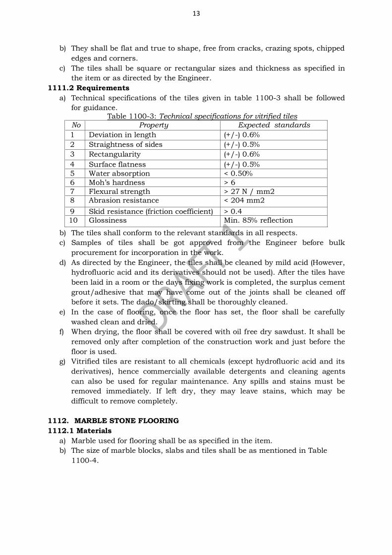
13
b) They shall be flat and true to shape, free from cracks, crazing spots, chipped
edges and corners.
c) The tiles shall be square or rectangular sizes and thickness as specified in
the item or as directed by the Engineer.
1111.2 Requirements
a) Technical specifications of the tiles given in table 1100-3 shall be followed
for guidance. Table 1100-3: Technical specifications for vitrified tiles
No Property Expected standards
1 Deviation in length (+/-) 0.6%
2 Straightness of sides (+/-) 0.5%
3 Rectangularity (+/-) 0.6%
4 Surface flatness (+/-) 0.5%
5 Water absorption < 0.50%
6 Moh’s hardness > 6
7 Flexural strength > 27 N / mm2
8 Abrasion resistance < 204 mm2
9 Skid resistance (friction coefficient) > 0.4
10 Glossiness Min. 85% reflection
b) The tiles shall conform to the relevant standards in all respects.
c) Samples of tiles shall be got approved from the Engineer before bulk
procurement for incorporation in the work.
d) As directed by the Engineer, the tiles shall be cleaned by mild acid (However,
hydrofluoric acid and its derivatives should not be used). After the tiles have
been laid in a room or the days fixing work is completed, the surplus cement
grout/adhesive that may have come out of the joints shall be cleaned off
before it sets. The dado/skirting shall be thoroughly cleaned.
e) In the case of flooring, once the floor has set, the floor shall be carefully
washed clean and dried.
f) When drying, the floor shall be covered with oil free dry sawdust. It shall be
removed only after completion of the construction work and just before the
floor is used.
g) Vitrified tiles are resistant to all chemicals (except hydrofluoric acid and its
derivatives), hence commercially available detergents and cleaning agents
can also be used for regular maintenance. Any spills and stains must be
removed immediately. If left dry, they may leave stains, which may be
difficult to remove completely.
1112. MARBLE STONE FLOORING
1112.1 Materials
a) Marble used for flooring shall be as specified in the item.
b) The size of marble blocks, slabs and tiles shall be as mentioned in Table
1100-4.
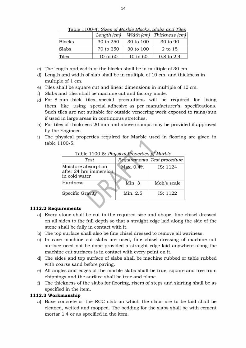
14
Table 1100-4: Sizes of Marble Blocks, Slabs and Tiles
Length (cm) Width (cm) Thickness (cm)
Blocks 30 to 250 30 to 100 30 to 90
Slabs 70 to 250 30 to 100 2 to 15
Tiles 10 to 60 10 to 60 0.8 to 2.4
c) The length and width of the blocks shall be in multiple of 30 cm.
d) Length and width of slab shall be in multiple of 10 cm. and thickness in
multiple of 1 cm.
e) Tiles shall be square cut and linear dimensions in multiple of 10 cm.
f) Slabs and tiles shall be machine cut and factory made.
g) For 8 mm thick tiles, special precautions will be required for fixing
them like using special adhesive as per manufacturer’s specifications. Such tiles are not suitable for outside veneering work exposed to rains/sun
if used in large areas in continuous stretches.
h) For tiles of thickness 20 mm and above cramps may be provided if approved
by the Engineer.
i) The physical properties required for Marble used in flooring are given in
table 1100-5.
Table 1100-5: Physical Properties of Marble
Test Requirements Test procedure
Moisture absorption after 24 hrs immersion in cold water
Max. 0.4%
IS: 1124
Hardness
Min. 3
Moh’s scale
Specific Gravity Min. 2.5 IS: 1122
1112.2 Requirements
a) Every stone shall be cut to the required size and shape, fine chisel dressed
on all sides to the full depth so that a straight edge laid along the side of the
stone shall be fully in contact with it.
b) The top surface shall also be fine chisel dressed to remove all waviness.
c) In case machine cut slabs are used, fine chisel dressing of machine cut
surface need not be done provided a straight edge laid anywhere along the
machine cut surfaces is in contact with every point on it.
d) The sides and top surface of slabs shall be machine rubbed or table rubbed
with coarse sand before paving.
e) All angles and edges of the marble slabs shall be true, square and free from
chippings and the surface shall be true and plane.
f) The thickness of the slabs for flooring, risers of steps and skirting shall be as
specified in the item.
1112.3 Workmanship
a) Base concrete or the RCC slab on which the slabs are to be laid shall be
cleaned, wetted and mopped. The bedding for the slabs shall be with cement
mortar 1:4 or as specified in the item.
15
b) The average thickness of the bedding mortar under the slab shall be 20 mm
and the thickness at any place under the slab shall be not less than 12 mm
c) The slab shall be washed clean before laying. It shall be laid on top, pressed,
tapped with wooden mallet and brought to level with the adjoining slabs. It
shall be lifted and laid aside.
d) The top surface of the mortar shall then be corrected by adding fresh mortar
at hollows. The mortar is allowed to harden a bit and cement slurry of honey
like consistency shall be spread over the same with cement at the rate of 4.4
kg/m2.
e) The edges of the slab already paved shall be buttered with grey or white
cement with or without admixture of pigment to match the shade of the
marble slabs as specified in the item.
f) The slab to be paved shall then be lowered gently back in position and
tapped with wooden mallet till it is properly bedded in level with and close to
the adjoining slabs with as fine a joint as possible.
g) Subsequent slabs shall be laid in the same manner. After each slab has been
laid, surplus cement on the surface of the slabs shall be cleaned off.
h) The flooring shall be cured for a minimum period of seven days.
i) The surface of the flooring as laid shall be true to levels, and slopes as
instructed by the Engineer.
j) Joint thickness shall not be more than 1 mm.
k) Due care shall be taken to match the grains of slabs. The slabs shall be
matched as shown in drawings or as instructed by the Engineer.
l) Slabs which are fixed in the floor adjoining the wall shall enter not less than
12 mm under the plaster skirting or dado. The junction between wall plaster
and floor shall be finished neatly and without waviness.
m) Marble slabs flooring shall also be laid in combination with other stones
and/or in simple regular pattern/design as described in item of work and/or
drawing.
n) Slight unevenness at the meeting edges of slabs shall then be removed by
fine chiselling and finished in the same manner as specified in clause 1106.
o) Finishing including polishing shall be done in the same manner as specified
in 1106 except that cement slurry with or without pigments shall not be
applied on the surface before each polishing
p) For skirting, the wall plastering shall be cut uniformly to the requisite depth
so that the skirting face shall have the minimum projection from the finished
face of wall.
q) In any case masonry shall not be cut to accommodate skirting as the cross
sectional area of the masonry may not be sufficient for the loads
transmitted.
r) The skirting or a step riser face shall be checked for plane and plumb and
corrected.
s) The top line of skirting and risers shall be truly horizontal and joints truly
vertical, except where otherwise indicated.
t) Wax polishing shall be done as detailed under 1106.
16
1112.4 Tolerances
Tolerance of +3% shall be allowed for the thickness specified. In respect of length
and breadth of slabs, a tolerance of +2% shall be allowed.
1113. KOTA STONE FLOORING
1113.1 Materials
a) The slabs shall be of selected quality, hard, sound, dense and homogeneous
in texture free from cracks, decay, weathering and flaws.
b) They shall be hand or machine cut to the requisite thickness.
c) They shall be of the colour indicated in the drawings or as instructed by the
Engineer.
d) The slabs shall have the top (exposed) face polished before being brought to
site, unless otherwise specified.
e) The slabs shall conform to the size required.
1113.2 Requirements
a) Every slab shall be cut to the required size and shape and fine chisel dressed
on the sides to the full depth so that a straight edge laid along the side of the
stone shall be in full contact with it. The sides (edges) shall be table rubbed
with coarse sand or machine rubbed before paving.
b) All angles and edges of the slabs shall be true, square and free from
chippings and the surface shall be true and plane.
c) The thickness of the slab, risers in steps and skirting after it is dressed shall
be as specified in the item.
1113.3 Workmanship
a) The workmanship shall be as per clause 1111 except that the edges of the
slabs to be jointed shall be buttered with grey cement, with admixture of
pigment to match the shade of the slab.
b) The thickness of the joints shall be minimum, as possible. In any location, it
shall not exceed 1 mm.
c) Preparation of surface for risers of steps, skirting and dado shall be as
specified in clause 1111.
d) Polishing and finishing shall be as described for marble flooring except that
first polishing with coarse grade carborandum stone shall not be done and
that cement slurry with or without pigment shall not be applied on the
surface before polishing.
e) Laying shall be as specified in clause 1111 except that the joints of the slabs
shall be set in grey cement mixed with pigment to match the shade of the
slabs.
f) Wax polishing shall be done as per requirement as detailed under 1111.
1113.4 Tolerances
Tolerance of ±2 mm shall be allowed for the thickness specified. In respect of length
and breadth of slabs, tolerance of ±5 mm for hand cut slabs and ±2 mm for
machine cut slabs shall be allowed.
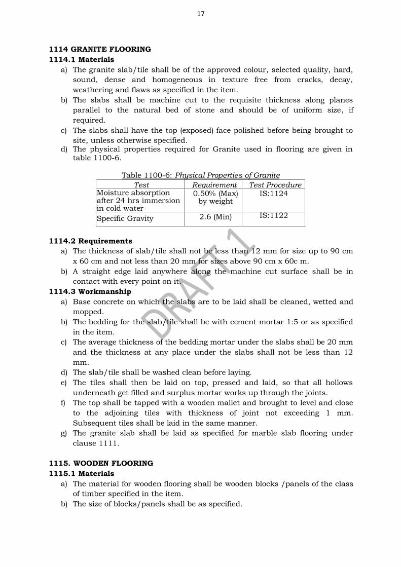
17
1114 GRANITE FLOORING
1114.1 Materials
a) The granite slab/tile shall be of the approved colour, selected quality, hard,
sound, dense and homogeneous in texture free from cracks, decay,
weathering and flaws as specified in the item.
b) The slabs shall be machine cut to the requisite thickness along planes
parallel to the natural bed of stone and should be of uniform size, if
required.
c) The slabs shall have the top (exposed) face polished before being brought to
site, unless otherwise specified. d) The physical properties required for Granite used in flooring are given in
table 1100-6.
Table 1100-6: Physical Properties of Granite
Test Requirement Test Procedure Moisture absorption after 24 hrs immersion in cold water
0.50% (Max) by weight
IS:1124
Specific Gravity 2.6 (Min) IS:1122
1114.2 Requirements
a) The thickness of slab/tile shall not be less than 12 mm for size up to 90 cm
x 60 cm and not less than 20 mm for sizes above 90 cm x 60c m.
b) A straight edge laid anywhere along the machine cut surface shall be in
contact with every point on it.
1114.3 Workmanship
a) Base concrete on which the slabs are to be laid shall be cleaned, wetted and
mopped.
b) The bedding for the slab/tile shall be with cement mortar 1:5 or as specified
in the item.
c) The average thickness of the bedding mortar under the slabs shall be 20 mm
and the thickness at any place under the slabs shall not be less than 12
mm.
d) The slab/tile shall be washed clean before laying.
e) The tiles shall then be laid on top, pressed and laid, so that all hollows
underneath get filled and surplus mortar works up through the joints.
f) The top shall be tapped with a wooden mallet and brought to level and close
to the adjoining tiles with thickness of joint not exceeding 1 mm.
Subsequent tiles shall be laid in the same manner.
g) The granite slab shall be laid as specified for marble slab flooring under
clause 1111.
1115. WOODEN FLOORING
1115.1 Materials
a) The material for wooden flooring shall be wooden blocks /panels of the class
of timber specified in the item.
b) The size of blocks/panels shall be as specified.
18
c) The blocks/panels shall be truly rectangular in shape with clean sharp
edges and true faces. The top and sides shall be planed true.
1115.2 Requirements
a) The timber used for making the blocks/panels shall be thoroughly seasoned
in accordance with IS: 1141.
b) After seasoning, the timber shall be treated with preservatives in accordance
with IS: 401.
c) The thickness of the blocks/panels shall be as specified.
d) The wooden block shall be placed on a 25 mm thick levelling course of
cement concrete 1:2:4 using 10 mm nominal size aggregates by volume
unless otherwise specified in the item.
1115.3 Workmanship
a) The surface of levelling concrete shall be finished with a wooden float to give
a sand paper finish, plane and true to level.
b) The finished level of the concrete shall be lower than the proposed finished
level of the flooring by the specified thickness of the wooden blocks/panels
plus a minimum of 1.5 mm.
c) The levelling concrete shall be cured for a week and then allowed to dry
thoroughly, before paving with wood blocks/panels.
d) The wood blocks/panels shall be first laid ‘dry’ to the margin and pattern shown in the drawings or as directed by the Engineer.
e) The blocks/panels shall fit closely and sides and end shall be planed further
if necessary to get closed and even joints.
f) After the blocks/panels have been fitted and matched they shall be removed
and stacked in such a way as to facilitate their repaving in the same order.
g) The surface of the levelling course shall be thoroughly cleaned and shall be
coated with a thin layer of approved adhesive.
h) The wood blocks/panels shall then be taken in turn serially, the bottom and
part of the sides coated thoroughly with the adhesive and pressed into place
to the required patterns on the previously coated concrete surface.
i) The joints of the work shall be very thin and fine.
j) When all the blocks/panels shall have been set in position, the surface shall
be cleaned, machined level and smooth.
k) The floor shall then be given a final smooth finish by rubbing down with
sand paper.
l) No wood of any kind shall be placed within 60 cm of any fire place or
chimney.
m) The floor shall be Bees waxed or polished with readymade wax polish or
given any other finish as required.
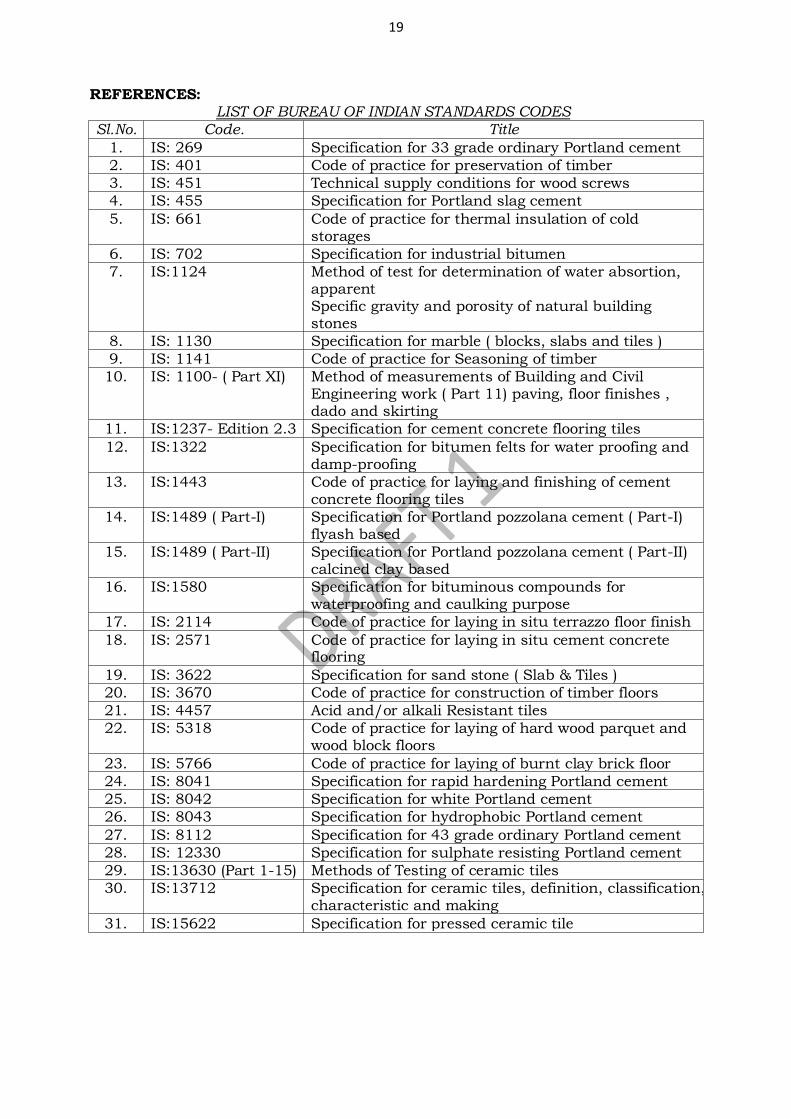
19
REFERENCES: LIST OF BUREAU OF INDIAN STANDARDS CODES
Sl.No. Code. Title
1. IS: 269 Specification for 33 grade ordinary Portland cement
2. IS: 401 Code of practice for preservation of timber
3. IS: 451 Technical supply conditions for wood screws
4. IS: 455 Specification for Portland slag cement
5. IS: 661 Code of practice for thermal insulation of cold storages
6. IS: 702 Specification for industrial bitumen
7. IS:1124 Method of test for determination of water absortion, apparent Specific gravity and porosity of natural building stones
8. IS: 1130 Specification for marble ( blocks, slabs and tiles )
9. IS: 1141 Code of practice for Seasoning of timber
10. IS: 1100- ( Part XI) Method of measurements of Building and Civil Engineering work ( Part 11) paving, floor finishes , dado and skirting
11. IS:1237- Edition 2.3 Specification for cement concrete flooring tiles
12. IS:1322 Specification for bitumen felts for water proofing and damp-proofing
13. IS:1443 Code of practice for laying and finishing of cement concrete flooring tiles
14. IS:1489 ( Part-I) Specification for Portland pozzolana cement ( Part-I) flyash based
15. IS:1489 ( Part-II) Specification for Portland pozzolana cement ( Part-II) calcined clay based
16. IS:1580 Specification for bituminous compounds for waterproofing and caulking purpose
17. IS: 2114 Code of practice for laying in situ terrazzo floor finish
18. IS: 2571 Code of practice for laying in situ cement concrete flooring
19. IS: 3622 Specification for sand stone ( Slab & Tiles )
20. IS: 3670 Code of practice for construction of timber floors
21. IS: 4457 Acid and/or alkali Resistant tiles
22. IS: 5318 Code of practice for laying of hard wood parquet and wood block floors
23. IS: 5766 Code of practice for laying of burnt clay brick floor
24. IS: 8041 Specification for rapid hardening Portland cement
25. IS: 8042 Specification for white Portland cement
26. IS: 8043 Specification for hydrophobic Portland cement
27. IS: 8112 Specification for 43 grade ordinary Portland cement
28. IS: 12330 Specification for sulphate resisting Portland cement
29. IS:13630 (Part 1-15) Methods of Testing of ceramic tiles
30. IS:13712 Specification for ceramic tiles, definition, classification, characteristic and making
31. IS:15622 Specification for pressed ceramic tile
Confidential - For private circulation only
SECTION 3200: NON-BITUMINOUS BASE AND SUB BASE COURSES
CONTENTS
3201 GENERAL
3202 WATER BOUND MACADAM
3202.1 Materials
3202.2 Requirements
3202.3 Construction
3202.4 Quality Control
3203 MECHANICALLY STABILIZED SOIL SUB BASE
3203.1 Construction
3203.2 Quality Control
3203.3 Rectification of surface irregularities
3204 LIME STABILIZED SOIL
3204.1 Materials
3204.2 Construction
3204.3 Quality Control
3204.4 Rectification of surface irregularities
3205 CEMENT MODIFIED SOIL
3205.1 Materials
3205.2 Construction
3205.3 Quality Control
3205.4 Rectification of surface irregularities
3206 GRANULAR SUBBASE
3206.1 Materials
3206.2 Construction
3206.3 Quality Control
3206.4 Rectification of surface irregularities
3207 WET MIX MACADAM
3207.1 Materials
3207.2 Construction
3207.3 Quality Control
3207.4 Rectification of surface irregularities
3208 CRUSHER-RUN MACADAM
3208.1 Materials
3208.2 Construction
3208.3 Quality Control
*****
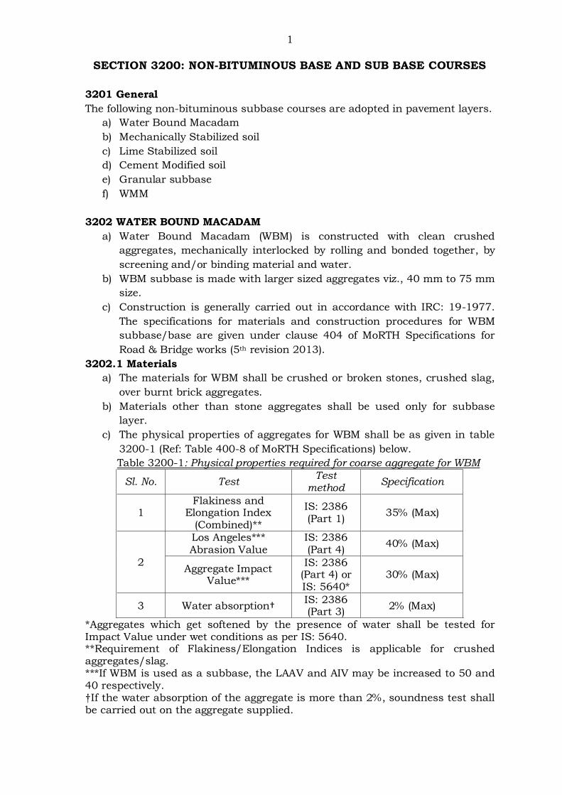
1
SECTION 3200: NON-BITUMINOUS BASE AND SUB BASE COURSES
3201 General
The following non-bituminous subbase courses are adopted in pavement layers.
a) Water Bound Macadam
b) Mechanically Stabilized soil
c) Lime Stabilized soil
d) Cement Modified soil
e) Granular subbase
f) WMM
3202 WATER BOUND MACADAM
a) Water Bound Macadam (WBM) is constructed with clean crushed
aggregates, mechanically interlocked by rolling and bonded together, by
screening and/or binding material and water.
b) WBM subbase is made with larger sized aggregates viz., 40 mm to 75 mm
size.
c) Construction is generally carried out in accordance with IRC: 19-1977.
The specifications for materials and construction procedures for WBM
subbase/base are given under clause 404 of MoRTH Specifications for
Road & Bridge works (5th revision 2013).
3202.1 Materials
a) The materials for WBM shall be crushed or broken stones, crushed slag,
over burnt brick aggregates.
b) Materials other than stone aggregates shall be used only for subbase
layer.
c) The physical properties of aggregates for WBM shall be as given in table
3200-1 (Ref: Table 400-8 of MoRTH Specifications) below.
Table 3200-1: Physical properties required for coarse aggregate for WBM
Sl. No. Test Test
method Specification
1 Flakiness and
Elongation Index (Combined)**
IS: 2386 (Part 1)
35% (Max)
2
Los Angeles*** Abrasion Value
IS: 2386 (Part 4)
40% (Max)
Aggregate Impact Value***
IS: 2386 (Part 4) or IS: 5640*
30% (Max)
3 Water absorption† IS: 2386 (Part 3)
2% (Max)
*Aggregates which get softened by the presence of water shall be tested for Impact Value under wet conditions as per IS: 5640. **Requirement of Flakiness/Elongation Indices is applicable for crushed aggregates/slag. ***If WBM is used as a subbase, the LAAV and AIV may be increased to 50 and 40 respectively. †If the water absorption of the aggregate is more than 2%, soundness test shall be carried out on the aggregate supplied.
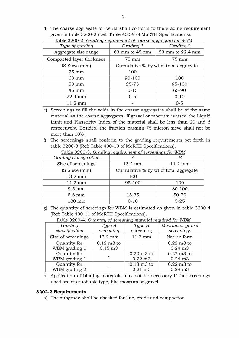
2
d) The coarse aggregate for WBM shall conform to the grading requirement
given in table 3200-2 (Ref: Table 400-9 of MoRTH Specifications).
Table 3200-2: Grading requirement of coarse aggregate for WBM
Type of grading Grading 1 Grading 2
Aggregate size range 63 mm to 45 mm 53 mm to 22.4 mm
Compacted layer thickness 75 mm 75 mm
IS Sieve (mm) Cumulative % by wt of total aggregate
75 mm 100 -
63 mm 90-100 100
53 mm 25-75 95-100
45 mm 0-15 65-90
22.4 mm 0-5 0-10
11.2 mm - 0-5
e) Screenings to fill the voids in the coarse aggregates shall be of the same
material as the coarse aggregates. If gravel or moorum is used the Liquid
Limit and Plassticity Index of the material shall be less than 20 and 6
respectively. Besides, the fraction passing 75 micron sieve shall not be
more than 10%.
f) The screenings shall conform to the grading requirements set forth in
table 3200-3 (Ref: Table 400-10 of MoRTH Specifications).
Table 3200-3: Grading requirement of screenings for WBM
Grading classification A B
Size of screenings 13.2 mm 11.2 mm
IS Sieve (mm) Cumulative % by wt of total aggregate
13.2 mm 100 -
11.2 mm 95-100 100
9.5 mm - 80-100
5.6 mm 15-35 50-70
180 mic 0-10 5-25
g) The quantity of screeings for WBM is estimated as given in table 3200-4
(Ref: Table 400-11 of MoRTH Specifications).
Table 3200-4: Quantity of screening material required for WBM
Grading classification
Type A screening
Type B screening
Moorum or gravel screenings
Size of screenings 13.2 mm 11.2 mm Not uniform
Quantity for WBM grading 1
0.12 m3 to 0.15 m3
- 0.22 m3 to 0.24 m3
Quantity for WBM grading 1
- 0.20 m3 to
0.22 m3 0.22 m3 to 0.24 m3
Quantity for WBM grading 2
- 0.18 m3 to
0.21 m3 0.22 m3 to 0.24 m3
h) Application of binding materials may not be necessary if the screenings
used are of crushable type, like moorum or gravel.
3202.2 Requirements
a) The subgrade shall be checked for line, grade and compaction.
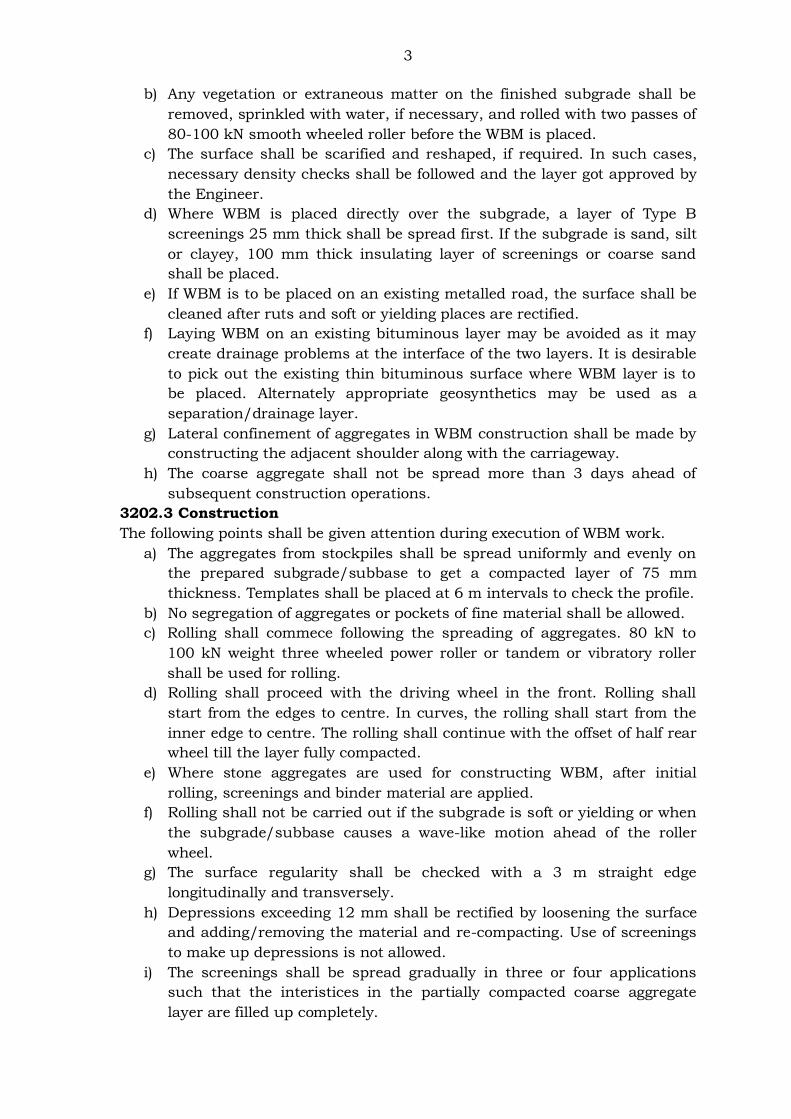
3
b) Any vegetation or extraneous matter on the finished subgrade shall be
removed, sprinkled with water, if necessary, and rolled with two passes of
80-100 kN smooth wheeled roller before the WBM is placed.
c) The surface shall be scarified and reshaped, if required. In such cases,
necessary density checks shall be followed and the layer got approved by
the Engineer.
d) Where WBM is placed directly over the subgrade, a layer of Type B
screenings 25 mm thick shall be spread first. If the subgrade is sand, silt
or clayey, 100 mm thick insulating layer of screenings or coarse sand
shall be placed.
e) If WBM is to be placed on an existing metalled road, the surface shall be
cleaned after ruts and soft or yielding places are rectified.
f) Laying WBM on an existing bituminous layer may be avoided as it may
create drainage problems at the interface of the two layers. It is desirable
to pick out the existing thin bituminous surface where WBM layer is to
be placed. Alternately appropriate geosynthetics may be used as a
separation/drainage layer.
g) Lateral confinement of aggregates in WBM construction shall be made by
constructing the adjacent shoulder along with the carriageway.
h) The coarse aggregate shall not be spread more than 3 days ahead of
subsequent construction operations.
3202.3 Construction
The following points shall be given attention during execution of WBM work.
a) The aggregates from stockpiles shall be spread uniformly and evenly on
the prepared subgrade/subbase to get a compacted layer of 75 mm
thickness. Templates shall be placed at 6 m intervals to check the profile.
b) No segregation of aggregates or pockets of fine material shall be allowed.
c) Rolling shall commece following the spreading of aggregates. 80 kN to
100 kN weight three wheeled power roller or tandem or vibratory roller
shall be used for rolling.
d) Rolling shall proceed with the driving wheel in the front. Rolling shall
start from the edges to centre. In curves, the rolling shall start from the
inner edge to centre. The rolling shall continue with the offset of half rear
wheel till the layer fully compacted.
e) Where stone aggregates are used for constructing WBM, after initial
rolling, screenings and binder material are applied.
f) Rolling shall not be carried out if the subgrade is soft or yielding or when
the subgrade/subbase causes a wave-like motion ahead of the roller
wheel.
g) The surface regularity shall be checked with a 3 m straight edge
longitudinally and transversely.
h) Depressions exceeding 12 mm shall be rectified by loosening the surface
and adding/removing the material and re-compacting. Use of screenings
to make up depressions is not allowed.
i) The screenings shall be spread gradually in three or four applications
such that the interistices in the partially compacted coarse aggregate
layer are filled up completely.
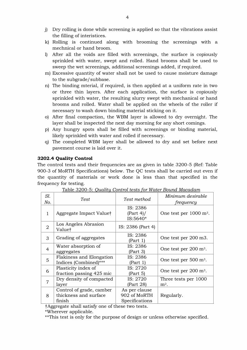
4
j) Dry rolling is done while screening is applied so that the vibrations assist
the filling of interistices.
k) Rolling is continued along with brooming the screenings with a
mechnical or hand broom.
l) After all the voids are filled with screenings, the surface is copiously
sprinkled with water, swept and rolled. Hand brooms shall be used to
sweep the wet screenings, additional screenings added, if required.
m) Excessive quantity of water shall not be used to cause moisture damage
to the subgrade/subbase.
n) The binding mterial, if required, is then applied at a uniform rate in two
or three thin layers. After each application, the surface is copiously
sprinkled with water, the resulting slurry swept with mechanical or hand
brooms and rolled. Water shall be applied on the wheels of the roller if
necessary to wash down binding material sticking on it.
o) After final compaction, the WBM layer is allowed to dry overnight. The
layer shall be inspected the next day morning for any short comings.
p) Any hungry spots shall be filled with screenings or binding material,
likely sprinkled with water and rolled if necessary.
q) The completed WBM layer shall be allowed to dry and set before next
pavement course is laid over it.
3202.4 Quality Control
The control tests and their frequencies are as given in table 3200-5 (Ref: Table
900-3 of MoRTH Specifications) below. The QC tests shall be carried out even if
the quantity of materials or work done is less than that specified in the
frequency for testing.
Table 3200-5: Quality Control tests for Water Bound Macadam
Sl.
No. Test Test method
Minimum desirable
frequency
1 Aggregate Impact Value† IS: 2386 (Part 4)/ IS:5640*
One test per 1000 m3.
2 Los Angeles Abrasion Value†
IS: 2386 (Part 4)
3 Grading of aggregates IS: 2386 (Part 1)
One test per 200 m3.
4 Water absorption of aggregates
IS: 2386 (Part 3)
One test per 200 m3.
5 Flakiness and Elongation Indices (Combined)***
IS: 2386 (Part 1)
One test per 500 m3.
6 Plasticity index of fraction passing 425 mic
IS: 2720 (Part 5)
One test per 200 m3.
7 Dry density of compacted layer
IS: 2720 (Part 28)
Three tests per 1000 m2.
8
Control of grade, camber thickness and surface finish
As per clause 902 of MoRTH Specifications
Regularly.
†Aggregate shall satisfy one of these two tests. *Wherever applicable. **This test is only for the purpose of design or unless otherwise specified.
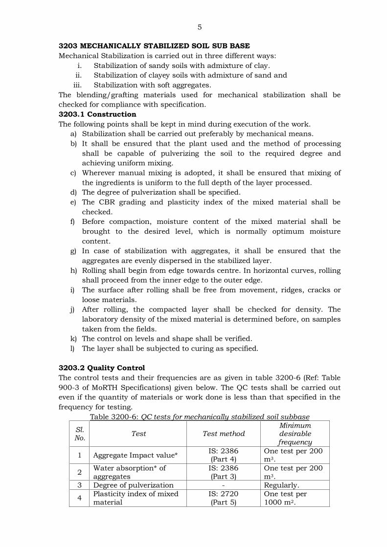
5
3203 MECHANICALLY STABILIZED SOIL SUB BASE
Mechanical Stabilization is carried out in three different ways:
i. Stabilization of sandy soils with admixture of clay.
ii. Stabilization of clayey soils with admixture of sand and
iii. Stabilization with soft aggregates.
The blending/grafting materials used for mechanical stabilization shall be
checked for compliance with specification.
3203.1 Construction
The following points shall be kept in mind during execution of the work.
a) Stabilization shall be carried out preferably by mechanical means.
b) It shall be ensured that the plant used and the method of processing
shall be capable of pulverizing the soil to the required degree and
achieving uniform mixing.
c) Wherever manual mixing is adopted, it shall be ensured that mixing of
the ingredients is uniform to the full depth of the layer processed.
d) The degree of pulverization shall be specified.
e) The CBR grading and plasticity index of the mixed material shall be
checked.
f) Before compaction, moisture content of the mixed material shall be
brought to the desired level, which is normally optimum moisture
content.
g) In case of stabilization with aggregates, it shall be ensured that the
aggregates are evenly dispersed in the stabilized layer.
h) Rolling shall begin from edge towards centre. In horizontal curves, rolling
shall proceed from the inner edge to the outer edge.
i) The surface after rolling shall be free from movement, ridges, cracks or
loose materials.
j) After rolling, the compacted layer shall be checked for density. The
laboratory density of the mixed material is determined before, on samples
taken from the fields.
k) The control on levels and shape shall be verified.
l) The layer shall be subjected to curing as specified.
3203.2 Quality Control
The control tests and their frequencies are as given in table 3200-6 (Ref: Table
900-3 of MoRTH Specifications) given below. The QC tests shall be carried out
even if the quantity of materials or work done is less than that specified in the
frequency for testing.
Table 3200-6: QC tests for mechanically stabilized soil subbase
Sl. No.
Test Test method Minimum desirable frequency
1 Aggregate Impact value* IS: 2386 (Part 4)
One test per 200 m3.
2 Water absorption* of aggregates
IS: 2386 (Part 3)
One test per 200 m3.
3 Degree of pulverization - Regularly.
4 Plasticity index of mixed material
IS: 2720 (Part 5)
One test per 1000 m2.
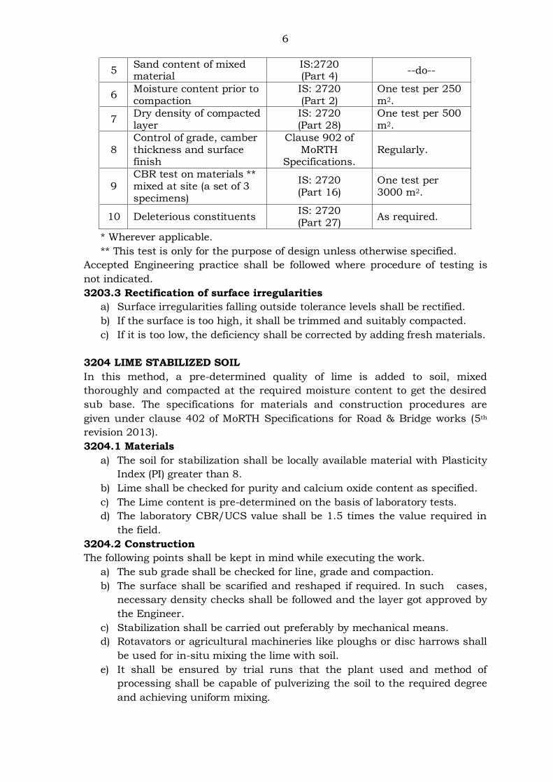
6
5 Sand content of mixed material
IS:2720 (Part 4)
--do--
6 Moisture content prior to compaction
IS: 2720 (Part 2)
One test per 250 m2.
7 Dry density of compacted layer
IS: 2720 (Part 28)
One test per 500 m2.
8 Control of grade, camber thickness and surface finish
Clause 902 of MoRTH
Specifications. Regularly.
9 CBR test on materials ** mixed at site (a set of 3 specimens)
IS: 2720 (Part 16)
One test per 3000 m2.
10 Deleterious constituents IS: 2720 (Part 27)
As required.
* Wherever applicable.
** This test is only for the purpose of design unless otherwise specified.
Accepted Engineering practice shall be followed where procedure of testing is
not indicated.
3203.3 Rectification of surface irregularities
a) Surface irregularities falling outside tolerance levels shall be rectified.
b) If the surface is too high, it shall be trimmed and suitably compacted.
c) If it is too low, the deficiency shall be corrected by adding fresh materials.
3204 LIME STABILIZED SOIL
In this method, a pre-determined quality of lime is added to soil, mixed
thoroughly and compacted at the required moisture content to get the desired
sub base. The specifications for materials and construction procedures are
given under clause 402 of MoRTH Specifications for Road & Bridge works (5th
revision 2013).
3204.1 Materials
a) The soil for stabilization shall be locally available material with Plasticity
Index (PI) greater than 8.
b) Lime shall be checked for purity and calcium oxide content as specified.
c) The Lime content is pre-determined on the basis of laboratory tests.
d) The laboratory CBR/UCS value shall be 1.5 times the value required in
the field.
3204.2 Construction
The following points shall be kept in mind while executing the work.
a) The sub grade shall be checked for line, grade and compaction.
b) The surface shall be scarified and reshaped if required. In such cases,
necessary density checks shall be followed and the layer got approved by
the Engineer.
c) Stabilization shall be carried out preferably by mechanical means.
d) Rotavators or agricultural machineries like ploughs or disc harrows shall
be used for in-situ mixing the lime with soil.
e) It shall be ensured by trial runs that the plant used and method of
processing shall be capable of pulverizing the soil to the required degree
and achieving uniform mixing.
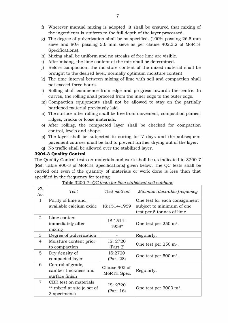
7
f) Wherever manual mixing is adopted, it shall be ensured that mixing of
the ingredients is uniform to the full depth of the layer processed.
g) The degree of pulverization shall be as specified. (100% passing 26.5 mm
sieve and 80% passing 5.6 mm sieve as per clause 402.3.2 of MoRTH
Specifications).
h) Mixing shall be uniform and no streaks of free lime are visible.
i) After mixing, the lime content of the mix shall be determined.
j) Before compaction, the moisture content of the mixed material shall be
brought to the desired level, normally optimum moisture content.
k) The time interval between mixing of lime with soil and compaction shall
not exceed three hours.
l) Rolling shall commence from edge and progress towards the centre. In
curves, the rolling shall proceed from the inner edge to the outer edge.
m) Compaction equipments shall not be allowed to stay on the partially
hardened material previously laid.
n) The surface after rolling shall be free from movement, compaction planes,
ridges, cracks or loose materials.
o) After rolling, the compacted layer shall be checked for compaction
control, levels and shape.
p) The layer shall be subjected to curing for 7 days and the subsequent
pavement courses shall be laid to prevent further drying out of the layer.
q) No traffic shall be allowed over the stabilized layer.
3204.3 Quality Control
The Quality Control tests on materials and work shall be as indicated in 3200-7
(Ref: Table 900-3 of MoRTH Specifications) given below. The QC tests shall be
carried out even if the quantity of materials or work done is less than that
specified in the frequency for testing.
Table 3200-7: QC tests for lime stabilized soil subbase
Sl.
No. Test Test method Minimum desirable frequency
1 Purity of lime and
available calcium oxide IS:1514-1959
One test for each consignment
subject to minimum of one
test per 5 tonnes of lime.
2 Lime content
immediately after
mixing
IS:1514-
1959* One test per 250 m2.
3 Degree of pulverization - Regularly.
4 Moisture content prior
to compaction
IS: 2720
(Part 2) One test per 250 m2.
5 Dry density of
compacted layer
IS:2720
(Part 28) One test per 500 m2.
6 Control of grade,
camber thickness and
surface finish
Clause 902 of
MoRTH Spec. Regularly.
7 CBR test on materials
** mixed at site (a set of
3 specimens)
IS: 2720
(Part 16) One test per 3000 m2.
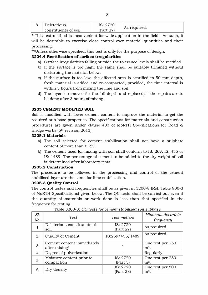
8
8 Deleterious
constituents of soil
IS: 2720
(Part 27) As required.
* This test method is inconvenient for wide application in the field. As such, it
will be desirable to exercise close control over material quantities and their
processing.
**Unless otherwise specified, this test is only for the purpose of design.
3204.4 Rectification of surface irregularities
a) Surface irregularities falling outside the tolerance levels shall be rectified.
b) If the surface is too high, the same shall be suitably trimmed without
disturbing the material below.
c) If the surface is too low, the affected area is scarified to 50 mm depth,
fresh material is added and re-compacted, provided, the time interval is
within 3 hours from mixing the lime and soil.
d) The layer is removed for the full depth and replaced, if the repairs are to
be done after 3 hours of mixing.
3205 CEMENT MODIFIED SOIL
Soil is modified with lower cement content to improve the material to get the
required sub base properties. The specifications for materials and construction
procedures are given under clause 403 of MoRTH Specifications for Road &
Bridge works (5th revision 2013).
3205.1 Materials
a) The soil selected for cement stabilization shall not have a sulphate
content of more than 0.2%.
b) The cement used for mixing with soil shall conform to IS: 269, IS: 455 or
IS: 1489. The percentage of cement to be added to the dry weight of soil
is determined after laboratory tests.
3205.2 Construction
The procedure to be followed in the processing and control of the cement
stabilised layer are the same for lime stabilization.
3205.3 Quality Control
The control testes and frequencies shall be as given in 3200-8 (Ref: Table 900-3
of MoRTH Specifications) given below. The QC tests shall be carried out even if
the quantity of materials or work done is less than that specified in the
frequency for testing.
Table 3200-8: QC tests for cement stabilized soil subbase
Sl.
No. Test Test method
Minimum desirable
frequency
1 Deleterious constituents of soil
IS: 2720 (Part 27)
As required.
2 Quality of Cement IS:269/455/1489 As required.
3 Cement content immediately after mixing*
- One test per 250 m2.
4 Degree of pulverization - Regularly.
5 Moisture content prior to compaction
IS: 2720 (Part 3)
One test per 250 m2.
6 Dry density IS: 2720 (Part 28)
One test per 500 m2.
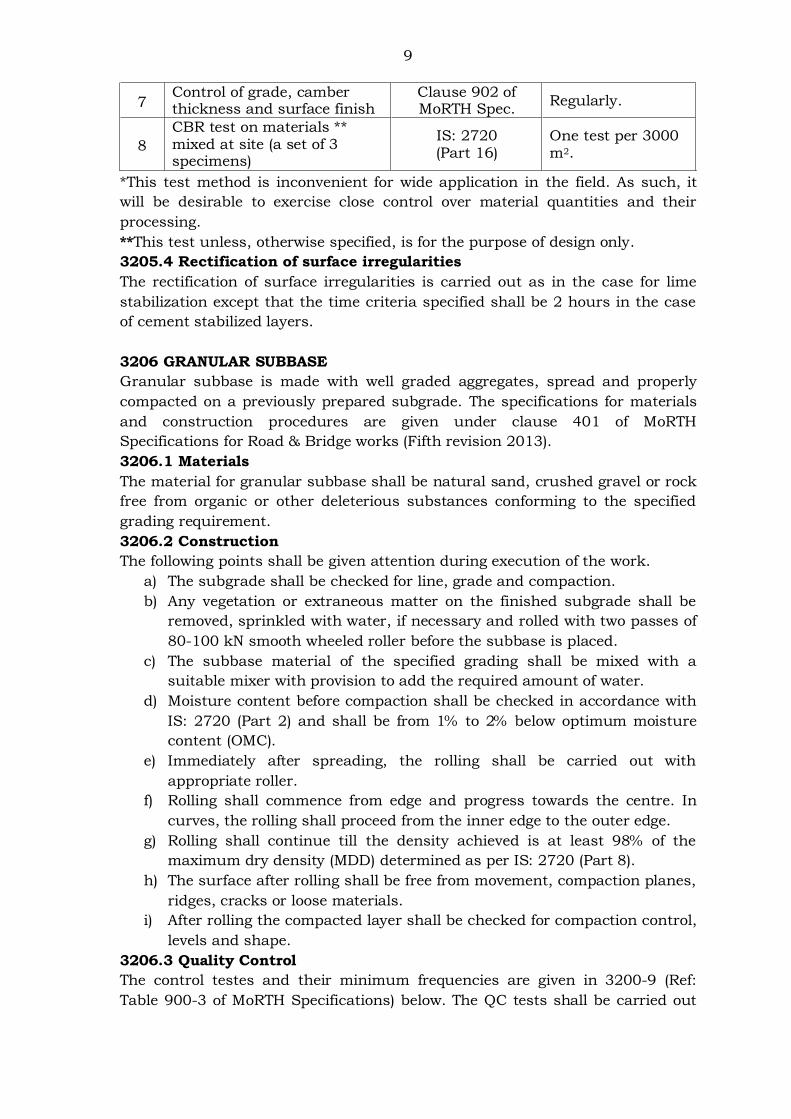
9
7 Control of grade, camber thickness and surface finish
Clause 902 of MoRTH Spec.
Regularly.
8
CBR test on materials ** mixed at site (a set of 3 specimens)
IS: 2720 (Part 16)
One test per 3000 m2.
*This test method is inconvenient for wide application in the field. As such, it
will be desirable to exercise close control over material quantities and their
processing.
**This test unless, otherwise specified, is for the purpose of design only.
3205.4 Rectification of surface irregularities
The rectification of surface irregularities is carried out as in the case for lime
stabilization except that the time criteria specified shall be 2 hours in the case
of cement stabilized layers.
3206 GRANULAR SUBBASE
Granular subbase is made with well graded aggregates, spread and properly
compacted on a previously prepared subgrade. The specifications for materials
and construction procedures are given under clause 401 of MoRTH
Specifications for Road & Bridge works (Fifth revision 2013).
3206.1 Materials
The material for granular subbase shall be natural sand, crushed gravel or rock
free from organic or other deleterious substances conforming to the specified
grading requirement.
3206.2 Construction
The following points shall be given attention during execution of the work.
a) The subgrade shall be checked for line, grade and compaction.
b) Any vegetation or extraneous matter on the finished subgrade shall be
removed, sprinkled with water, if necessary and rolled with two passes of
80-100 kN smooth wheeled roller before the subbase is placed.
c) The subbase material of the specified grading shall be mixed with a
suitable mixer with provision to add the required amount of water.
d) Moisture content before compaction shall be checked in accordance with
IS: 2720 (Part 2) and shall be from 1% to 2% below optimum moisture
content (OMC).
e) Immediately after spreading, the rolling shall be carried out with
appropriate roller.
f) Rolling shall commence from edge and progress towards the centre. In
curves, the rolling shall proceed from the inner edge to the outer edge.
g) Rolling shall continue till the density achieved is at least 98% of the
maximum dry density (MDD) determined as per IS: 2720 (Part 8).
h) The surface after rolling shall be free from movement, compaction planes,
ridges, cracks or loose materials.
i) After rolling the compacted layer shall be checked for compaction control,
levels and shape.
3206.3 Quality Control
The control testes and their minimum frequencies are given in 3200-9 (Ref:
Table 900-3 of MoRTH Specifications) below. The QC tests shall be carried out
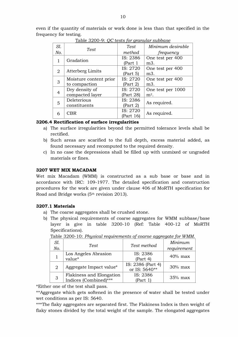
10
even if the quantity of materials or work done is less than that specified in the
frequency for testing.
Table 3200-9: QC tests for granular subbase
Sl.
No. Test
Test
method
Minimum desirable
frequency
1 Gradation IS: 2386 (Part 1
One test per 400 m3.
2 Atterberg Limits IS: 2720 (Part 5)
One test per 400 m3.
3 Moisture content prior to compaction
IS: 2720 (Part 2)
One test per 400 m3.
4 Dry density of compacted layer
IS: 2720 (Part 28)
One test per 1000 m2.
5 Deleterious constituents
IS: 2386 (Part 2)
As required.
6 CBR IS: 2720 (Part 16)
As required.
3206.4 Rectification of surface irregularities
a) The surface irregularities beyond the permitted tolerance levels shall be
rectified.
b) Such areas are scarified to the full depth, excess material added, as
found necessary and recomputed to the required density.
c) In no case the depressions shall be filled up with unmixed or ungraded
materials or fines.
3207 WET MIX MACADAM
Wet mix Macadam (WMM) is constructed as a sub base or base and in
accordance with IRC: 109-1977. The detailed specification and construction
procedures for the work are given under clause 406 of MoRTH specification for
Road and Bridge works (5th revision 2013).
3207.1 Materials
a) The coarse aggregates shall be crushed stone.
b) The physical requirements of coarse aggregates for WMM subbase/base
layer is give in table 3200-10 (Ref: Table 400-12 of MoRTH
Specifications).
Table 3200-10: Physical requirements of coarse aggregate for WMM.
Sl.
No. Test Test method
Minimum
requirement
1 Los Angeles Abrasion value*
IS: 2386 (Part 4)
40% max
2 Aggregate Impact value* IS: 2386 (Part 4)
or IS: 5640** 30% max
3 Flakiness and Elongation Indices (Combined)***
IS: 2386 (Part 1)
35% max
*Either one of the test shall pass.
**Aggregate which gets softened in the presence of water shall be tested under
wet conditions as per IS: 5640.
***The flaky aggregates are separated first. The Flakiness Index is then weight of
flaky stones divided by the total weight of the sample. The elongated aggregates
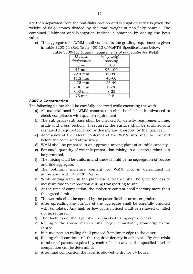
11
are then separated from the non-flaky portion and Elongation Index is given the
weight of flaky stones divided by the total weight of non-flaky sample. The
combined Flakiness and Elongation Indices is obtained by adding the both
values.
c) The aggregates for WMM shall conform to the grading requirements given
in table 3200-11 (Ref: Table 400-13 of MoRTH Specifications) below.
Table 3200-11: Grading requirements of aggregates for WMM
IS sieve designation
% by weight passing
53 mm 100
45 mm 95-100
22.4 mm 60-80
11.2 mm 40-60
4.75 mm 25-40
2.36 mm 15-30
600 mic 8-22
75 mic 0-5
3207.2 Construction
The following points shall be carefully observed while executing the work.
a) All material used for WMM construction shall be checked in advanced to
check compliance with quality requirement.
b) The sub grade/sub base shall be checked for density requirement, lime,
grade and cross section. If required, the surface shall be scarified and
reshaped if required followed by density and approved by the Engineer.
c) Adequency of the lateral conferent of the WMM mix shall be checked
before the comenced of the work.
d) WMM shall be prepared in an approved mixing plant of suitable capacity.
e) For small quantity of wet mix preparation mixing in a concrete mixer can
be permitted.
f) The mixing shall be uniform and there should be no segregation of course
and fine aggregate.
g) The optimum moisture content for WMM mix is determined in
accordance with IS: 2720 (Part -8).
h) While adding water in the plant due allowance shall be given for loss of
moisture due to evaporation during transporting to site.
i) At the time of compaction, the moisture content shall not vary more than
the agreed limit.
j) The wet mix shall be spread by the paver finisher or nuter grader.
k) After spreading the surface of the aggregate shall be carefully checked
with templater. Any high or low spots noticed shall be removed or filled
up, as required.
l) The thickness of the layer shall be checked using depth blocks.
m) Rolling of the spread material shall begin immediately from edge to the
centre.
n) In curve portion rolling shall procced from inner edge to the outer.
o) Rolling shall continue till the required density is achieved. By site trials
number of passes required by each roller to advice the specified level of
compaction can be determind.
p) After final compaction the layer is allowed to dry for 24 hours.
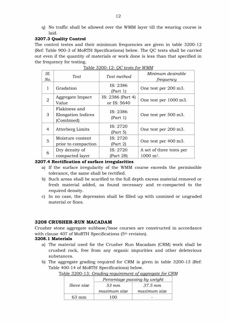
12
q) No traffic shall be allowed over the WMM layer till the wearing course is
laid.
3207.3 Quality Control
The control testes and their minimum frequencies are given in table 3200-12
(Ref: Table 900-3 of MoRTH Specifications) below. The QC tests shall be carried
out even if the quantity of materials or work done is less than that specified in
the frequency for testing.
Table 3200-12: QC tests for WMM
Sl.
No. Test Test method
Minimum desirable
frequency
1 Gradation IS: 2386
(Part 1) One test per 200 m3.
2 Aggregate Impact
Value
IS: 2386 (Part 4)
or IS: 5640 One test per 1000 m3.
3
Flakiness and
Elongation Indices
(Combined)
IS: 2386
(Part 1) One test per 500 m3.
4 Atterberg Limits IS: 2720
(Part 5) One test per 200 m3.
5 Moisture content
prior to compaction
IS: 2720
(Part 2) One test per 400 m3.
6 Dry density of
compacted layer
IS: 2720
(Part 28)
A set of three tests per
1000 m2.
3207.4 Rectification of surface irregularities
a) If the surface irregularity of the WMM course exceeds the permissible
tolerance, the same shall be rectified.
b) Such areas shall be scarified to the full depth excess material removed or
fresh material added, as found necessary and re-compacted to the
required density.
c) In no case, the depression shall be filled up with unmixed or ungraded
material or fines.
3208 CRUSHER-RUN MACADAM
Crusher stone aggregate subbase/base courses are constructed in accordance
with clause 407 of MoRTH Specifications (5th revision). 3208.1 Materials
a) The material used for the Crusher Run Macadam (CRM) work shall be
crushed rock, free from any organic impurities and other deleterious
substances.
b) The aggregate grading required for CRM is given in table 3200-13 (Ref:
Table 400-14 of MoRTH Specifications) below.
Table 3200-13: Grading requirement of aggregate for CRM
Sieve size
Percentage passing by weight
53 mm
maximum size
37.5 mm
maximum size
63 mm 100 -
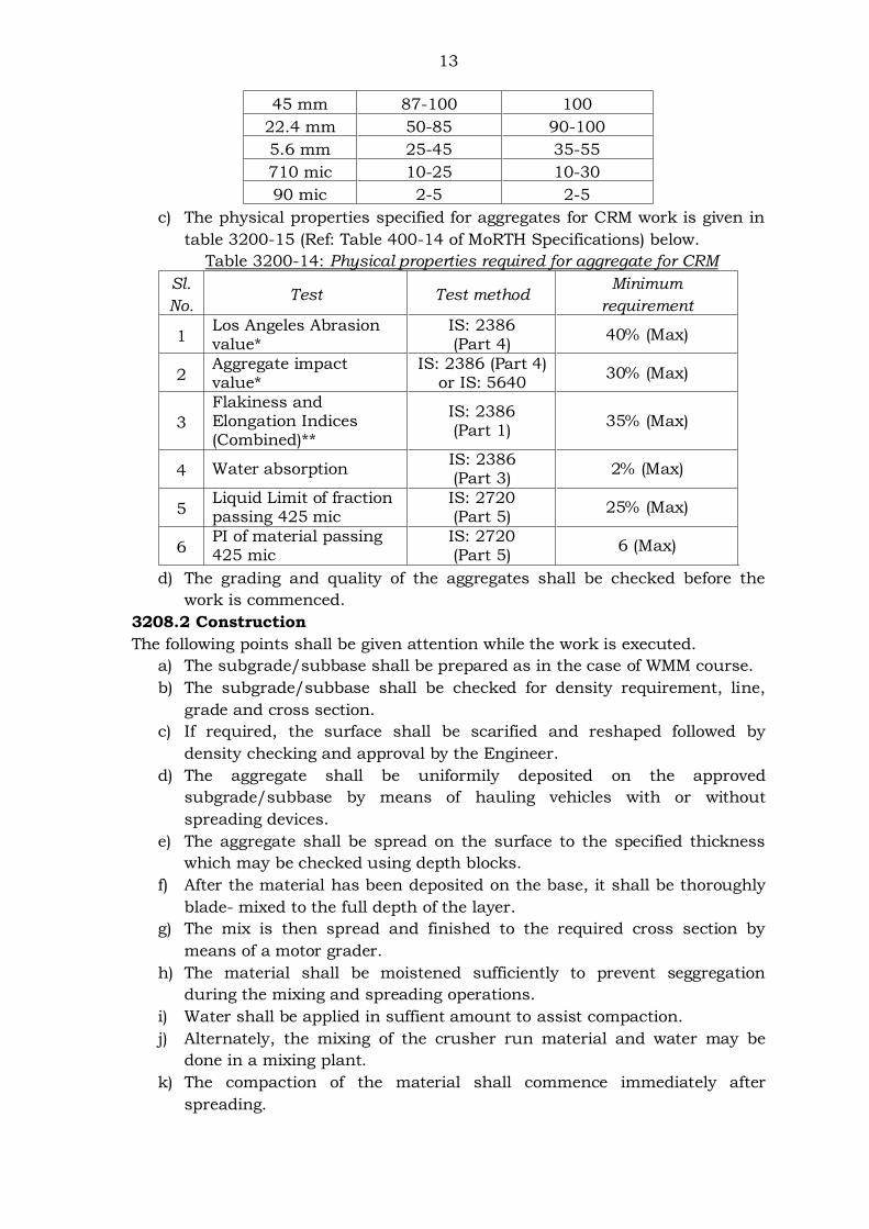
13
45 mm 87-100 100
22.4 mm 50-85 90-100
5.6 mm 25-45 35-55
710 mic 10-25 10-30
90 mic 2-5 2-5
c) The physical properties specified for aggregates for CRM work is given in
table 3200-15 (Ref: Table 400-14 of MoRTH Specifications) below.
Table 3200-14: Physical properties required for aggregate for CRM
Sl.
No. Test Test method
Minimum
requirement
1 Los Angeles Abrasion value*
IS: 2386 (Part 4)
40% (Max)
2 Aggregate impact value*
IS: 2386 (Part 4) or IS: 5640
30% (Max)
3
Flakiness and Elongation Indices (Combined)**
IS: 2386 (Part 1)
35% (Max)
4 Water absorption IS: 2386 (Part 3)
2% (Max)
5 Liquid Limit of fraction passing 425 mic
IS: 2720 (Part 5)
25% (Max)
6 PI of material passing 425 mic
IS: 2720 (Part 5)
6 (Max)
d) The grading and quality of the aggregates shall be checked before the
work is commenced.
3208.2 Construction
The following points shall be given attention while the work is executed.
a) The subgrade/subbase shall be prepared as in the case of WMM course.
b) The subgrade/subbase shall be checked for density requirement, line,
grade and cross section.
c) If required, the surface shall be scarified and reshaped followed by
density checking and approval by the Engineer.
d) The aggregate shall be uniformily deposited on the approved
subgrade/subbase by means of hauling vehicles with or without
spreading devices.
e) The aggregate shall be spread on the surface to the specified thickness
which may be checked using depth blocks.
f) After the material has been deposited on the base, it shall be thoroughly
blade- mixed to the full depth of the layer.
g) The mix is then spread and finished to the required cross section by
means of a motor grader.
h) The material shall be moistened sufficiently to prevent seggregation
during the mixing and spreading operations.
i) Water shall be applied in suffient amount to assist compaction.
j) Alternately, the mixing of the crusher run material and water may be
done in a mixing plant.
k) The compaction of the material shall commence immediately after
spreading.
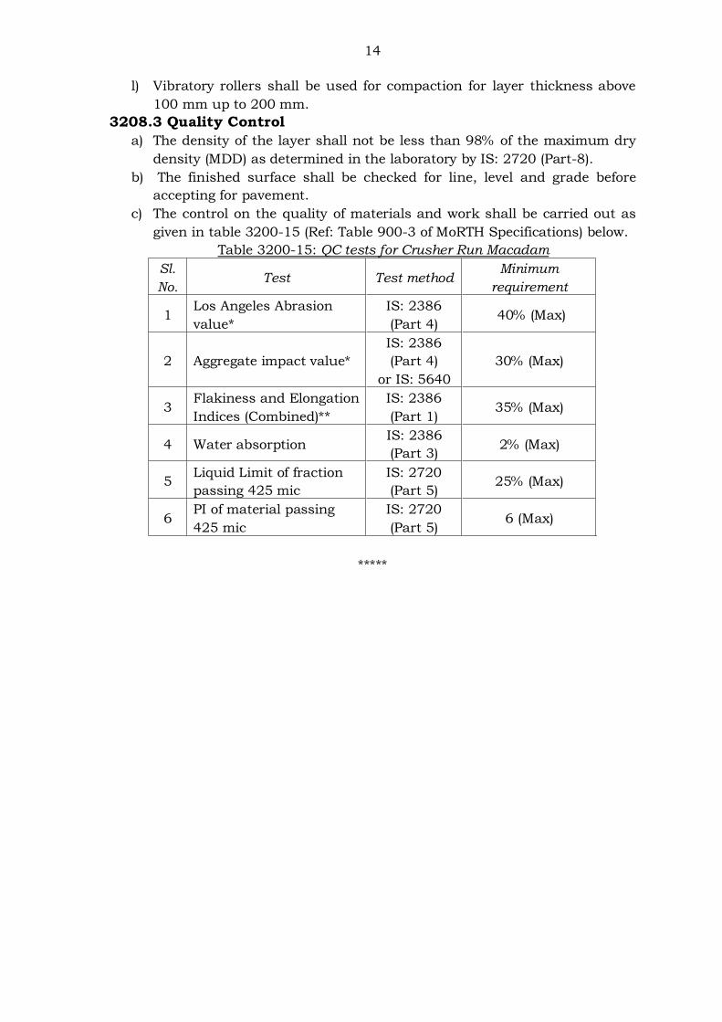
14
l) Vibratory rollers shall be used for compaction for layer thickness above
100 mm up to 200 mm.
3208.3 Quality Control
a) The density of the layer shall not be less than 98% of the maximum dry
density (MDD) as determined in the laboratory by IS: 2720 (Part-8).
b) The finished surface shall be checked for line, level and grade before
accepting for pavement.
c) The control on the quality of materials and work shall be carried out as
given in table 3200-15 (Ref: Table 900-3 of MoRTH Specifications) below.
Table 3200-15: QC tests for Crusher Run Macadam
Sl.
No. Test Test method
Minimum
requirement
1 Los Angeles Abrasion
value*
IS: 2386
(Part 4) 40% (Max)
2 Aggregate impact value*
IS: 2386
(Part 4)
or IS: 5640
30% (Max)
3 Flakiness and Elongation
Indices (Combined)**
IS: 2386
(Part 1) 35% (Max)
4 Water absorption IS: 2386
(Part 3) 2% (Max)
5 Liquid Limit of fraction
passing 425 mic
IS: 2720
(Part 5) 25% (Max)
6 PI of material passing
425 mic
IS: 2720
(Part 5) 6 (Max)
*****
Confidential – For private circulation only
SECTION 3300: BITUMINOUS BASE AND SURFACE COURSES
CONTENTS
3301 GENERAL
3302 BITUMINOUS MACADAM (BM)
3302.1 Materials
3302.2 Combined grading and binder content
3302.3 Preparation of the surface
3302.4 Construction procedure
3302.5 Mix preparation
3302.6 Spreading and rolling of the mix
3302.7 Quality Control
3303 DENSE BITUMINOUS MACADAM (DBM)
3303.1 Materials
3303.2 Combined aggregate grading and binder content
3303.3 Mix design
3303.4 Job mix formula
3303.5 Approval of the job mix formula
3303.6 Plant and field trials
3303.7 Construction procedure
3303.8 Spreading & compaction
3303.9 Quality Control
3304 SAND BITUMEN MIX
3304.1 Materials
3304.2 Construction
3304.3 Quality control
3304.4 Rectification of surface irregularities
3305 SINGLE COAT SURFACE DRESSING
3305.1 Construction
3306 TWO COAT SURFACE DRESSING
3306.1 Quality control
3306.2 Surface regularity
3307 SURFACE DRESSING WITH PRE-COATED AGGREGATE
3307.1 Construction
3308 OPEN-GRADED PREMIX SURFACING
3308.1 Materials
3308.2 Construction
3308.3 Quality control
3308.4 Rectification of surface irregularities
3309. CLOSE-GRADED PREMIX SURFACING/MIX SEAL SURFACING
3309.1 Materials
3309.2 Construction
3310 SEAL COAT
3310.1 Materials
3310.2 Construction
3311 BITUMINOUS CONCRETE SURFACING
3311.1 Materials
3311.2 Bituminous Concrete mix requirement
3311.3 Job mix formula
3311.4 Plant and field trials
3311.5 Construction
3311.6 Spreading and compaction
3311.7 Quality control
3312 STONE MATRIX ASPHALT (SMA)
3312.1 Materials
3312.1.1 Coarse aggregate
3312.1.2 Fine aggregates
3312.1.3 Mineral filler
3312.1.4 Stabilizer additive
3312.2 Aggregate grading
3312.3 Mix requirements
3312.4 Mix Design
3312.5 SMA mix production
3312.6 Construction
3312.7 Density and levels of the compacted layer
3312.8 Quality control
3313 SEMI-DENSE BITUMINOUS CONCRETE
3313.1 Materials
3313.2 Mix requirements
3313.3 Job mix formula
3313.4 Plant and field trials
3313.5 Construction
3313.6 Spreading and compaction
3313.7 Quality control
*****

1
SECTION 3300: BITUMINOUS BASE AND SURFACE COURSES
3301 GENERAL
The bituminous base courses included in the MoRTH Specifications for Road and
Bridge works (5th revision) and which are normally used in pavement construction
are:
(a) Bituminous Macadam
(b) Dense Bituminous Macadam
(c) Sand bitumen
The bituminous surface courses include:
(a) Surface dressing
(b) Open-graded premix surfacing
(c) Close-graded premix surfacing/Mixed seal surfacing
(d) Seal coat
(e) Bituminous Concrete
(f) Stone Matrix Asphalt (SMA)
(g) Semi-dense Bituminous Concrete
Some of the bituminous pavement layers commonly used in PWD road works are
discussed in this section.
3302 BITUMINOUS MACADAM (BM)
Constructing bituminous macadam base shall generally be done as per IRC: 27-
1967. The specifications and construction procedure of Bituminous Macadam is
giver under clause 504 of MoRTH Specifications (5th revision).
3302.1 Materials
a) The bitumen shall be viscosity graded paving bitumen complying with IS: 73
or as specified in the contract.
b) The coarse aggregate shall be crushed rock retaining on 2.36 mm sieve.
c) The physical properties of coarse aggregate shall be as given in table 3300-1
(Ref: Table 500-6 of MoRTH Specifications)below.
Table 3300-1: Physical requirements for coarse aggregates for BM
Property Test Test method Specification
Cleanliness Grain size analysis
IS: 2386 (Part 1)
Max 5% passing 75 micron sieve
Particle shape
Flakiness and Elongation Index
(Combined)
IS: 2386 (Part 1)
Max 35%
Strength*
Los Angeles Abrasion Value
IS: 2386 (Part 4)
Max 40%
Aggregate Impact Value
IS: 2386 (Part 4)
Max 30%
Durability
Soundness – Sodium Sulphate
(5 cycles)
IS: 2386 (Part 5)
Max 12%
Soundness – Magnesium
Sulphate (5 cycles)
IS: 2386 (Part 5)
Max 18%
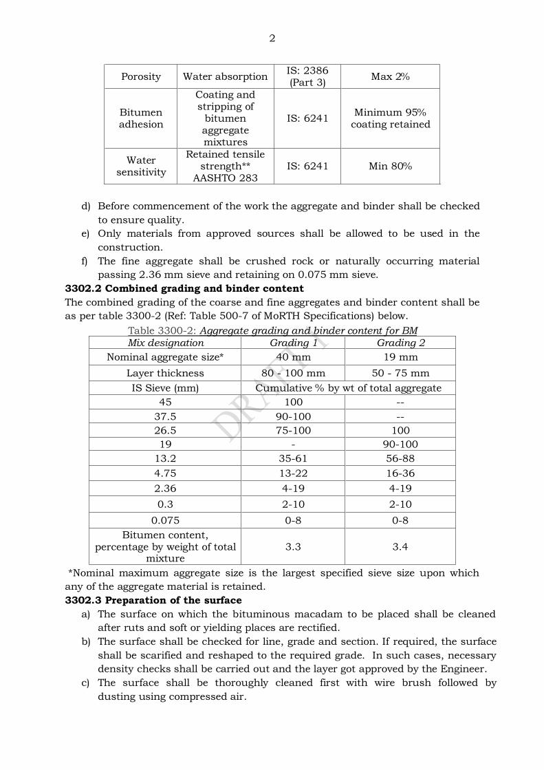
2
Porosity Water absorption IS: 2386 (Part 3)
Max 2%
Bitumen adhesion
Coating and stripping of
bitumen aggregate mixtures
IS: 6241 Minimum 95%
coating retained
Water sensitivity
Retained tensile strength**
AASHTO 283 IS: 6241 Min 80%
d) Before commencement of the work the aggregate and binder shall be checked
to ensure quality.
e) Only materials from approved sources shall be allowed to be used in the
construction.
f) The fine aggregate shall be crushed rock or naturally occurring material
passing 2.36 mm sieve and retaining on 0.075 mm sieve.
3302.2 Combined grading and binder content
The combined grading of the coarse and fine aggregates and binder content shall be
as per table 3300-2 (Ref: Table 500-7 of MoRTH Specifications) below.
Table 3300-2: Aggregate grading and binder content for BM
Mix designation Grading 1 Grading 2
Nominal aggregate size* 40 mm 19 mm
Layer thickness 80 - 100 mm 50 - 75 mm
IS Sieve (mm) Cumulative % by wt of total aggregate
45 100 --
37.5 90-100 --
26.5 75-100 100
19 - 90-100
13.2 35-61 56-88
4.75 13-22 16-36
2.36 4-19 4-19
0.3 2-10 2-10
0.075 0-8 0-8
Bitumen content, percentage by weight of total
mixture 3.3 3.4
*Nominal maximum aggregate size is the largest specified sieve size upon which
any of the aggregate material is retained.
3302.3 Preparation of the surface
a) The surface on which the bituminous macadam to be placed shall be cleaned
after ruts and soft or yielding places are rectified.
b) The surface shall be checked for line, grade and section. If required, the surface
shall be scarified and reshaped to the required grade. In such cases, necessary
density checks shall be carried out and the layer got approved by the Engineer.
c) The surface shall be thoroughly cleaned first with wire brush followed by
dusting using compressed air.
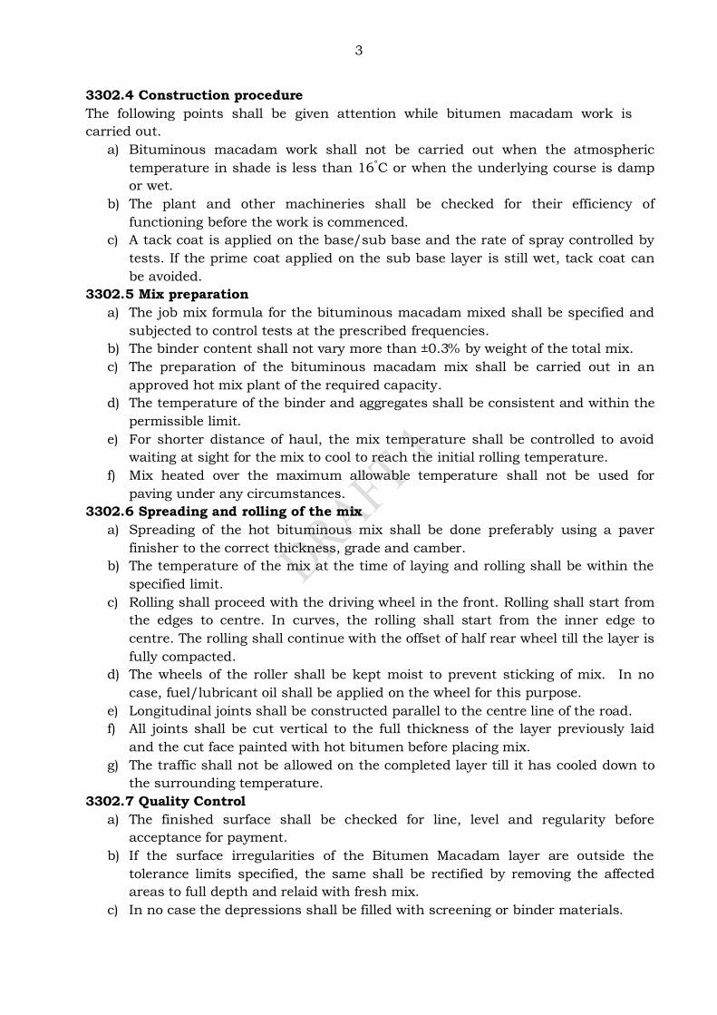
3
3302.4 Construction procedure
The following points shall be given attention while bitumen macadam work is
carried out.
a) Bituminous macadam work shall not be carried out when the atmospheric
temperature in shade is less than 16°C or when the underlying course is damp
or wet.
b) The plant and other machineries shall be checked for their efficiency of
functioning before the work is commenced.
c) A tack coat is applied on the base/sub base and the rate of spray controlled by
tests. If the prime coat applied on the sub base layer is still wet, tack coat can
be avoided.
3302.5 Mix preparation
a) The job mix formula for the bituminous macadam mixed shall be specified and
subjected to control tests at the prescribed frequencies.
b) The binder content shall not vary more than ±0.3% by weight of the total mix.
c) The preparation of the bituminous macadam mix shall be carried out in an
approved hot mix plant of the required capacity.
d) The temperature of the binder and aggregates shall be consistent and within the
permissible limit.
e) For shorter distance of haul, the mix temperature shall be controlled to avoid
waiting at sight for the mix to cool to reach the initial rolling temperature.
f) Mix heated over the maximum allowable temperature shall not be used for
paving under any circumstances.
3302.6 Spreading and rolling of the mix
a) Spreading of the hot bituminous mix shall be done preferably using a paver
finisher to the correct thickness, grade and camber.
b) The temperature of the mix at the time of laying and rolling shall be within the
specified limit.
c) Rolling shall proceed with the driving wheel in the front. Rolling shall start from
the edges to centre. In curves, the rolling shall start from the inner edge to
centre. The rolling shall continue with the offset of half rear wheel till the layer is
fully compacted.
d) The wheels of the roller shall be kept moist to prevent sticking of mix. In no
case, fuel/lubricant oil shall be applied on the wheel for this purpose.
e) Longitudinal joints shall be constructed parallel to the centre line of the road.
f) All joints shall be cut vertical to the full thickness of the layer previously laid
and the cut face painted with hot bitumen before placing mix.
g) The traffic shall not be allowed on the completed layer till it has cooled down to
the surrounding temperature.
3302.7 Quality Control
a) The finished surface shall be checked for line, level and regularity before
acceptance for payment.
b) If the surface irregularities of the Bitumen Macadam layer are outside the
tolerance limits specified, the same shall be rectified by removing the affected
areas to full depth and relaid with fresh mix.
c) In no case the depressions shall be filled with screening or binder materials.
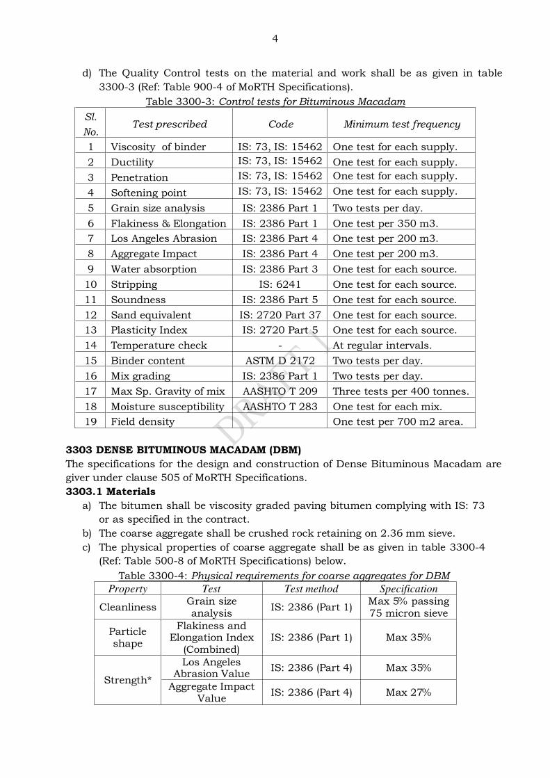
4
d) The Quality Control tests on the material and work shall be as given in table
3300-3 (Ref: Table 900-4 of MoRTH Specifications).
Table 3300-3: Control tests for Bituminous Macadam
Sl.
No. Test prescribed Code Minimum test frequency
1 Viscosity of binder IS: 73, IS: 15462 One test for each supply.
2 Ductility IS: 73, IS: 15462 One test for each supply.
3 Penetration IS: 73, IS: 15462 One test for each supply.
4 Softening point IS: 73, IS: 15462 One test for each supply.
5 Grain size analysis IS: 2386 Part 1 Two tests per day.
6 Flakiness & Elongation IS: 2386 Part 1 One test per 350 m3.
7 Los Angeles Abrasion IS: 2386 Part 4 One test per 200 m3.
8 Aggregate Impact IS: 2386 Part 4 One test per 200 m3.
9 Water absorption IS: 2386 Part 3 One test for each source.
10 Stripping IS: 6241 One test for each source.
11 Soundness IS: 2386 Part 5 One test for each source.
12 Sand equivalent IS: 2720 Part 37 One test for each source.
13 Plasticity Index IS: 2720 Part 5 One test for each source.
14 Temperature check - At regular intervals.
15 Binder content ASTM D 2172 Two tests per day.
16 Mix grading IS: 2386 Part 1 Two tests per day.
17 Max Sp. Gravity of mix AASHTO T 209 Three tests per 400 tonnes.
18 Moisture susceptibility AASHTO T 283 One test for each mix.
19 Field density One test per 700 m2 area.
3303 DENSE BITUMINOUS MACADAM (DBM)
The specifications for the design and construction of Dense Bituminous Macadam are
giver under clause 505 of MoRTH Specifications.
3303.1 Materials
a) The bitumen shall be viscosity graded paving bitumen complying with IS: 73
or as specified in the contract.
b) The coarse aggregate shall be crushed rock retaining on 2.36 mm sieve.
c) The physical properties of coarse aggregate shall be as given in table 3300-4
(Ref: Table 500-8 of MoRTH Specifications) below.
Table 3300-4: Physical requirements for coarse aggregates for DBM
Property Test Test method Specification
Cleanliness Grain size analysis
IS: 2386 (Part 1) Max 5% passing 75 micron sieve
Particle shape
Flakiness and Elongation Index
(Combined) IS: 2386 (Part 1) Max 35%
Strength*
Los Angeles Abrasion Value
IS: 2386 (Part 4) Max 35%
Aggregate Impact Value
IS: 2386 (Part 4) Max 27%
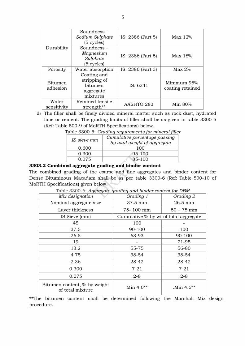
5
Durability
Soundness – Sodium Sulphate
(5 cycles) IS: 2386 (Part 5) Max 12%
Soundness – Magnesium
Sulphate (5 cycles)
IS: 2386 (Part 5) Max 18%
Porosity Water absorption IS: 2386 (Part 3) Max 2%
Bitumen adhesion
Coating and stripping of
bitumen aggregate mixtures
IS: 6241 Minimum 95%
coating retained
Water sensitivity
Retained tensile strength**
AASHTO 283 Min 80%
d) The filler shall be finely divided mineral matter such as rock dust, hydrated
lime or cement. The grading limits of filler shall be as given in table 3300-5
(Ref: Table 500-9 of MoRTH Specifications) below.
Table 3300-5: Grading requirements for mineral filler
IS sieve mm Cumulative percentage passing
by total weight of aggregate
0.600 100
0.300 95-100
0.075 85-100
3303.2 Combined aggregate grading and binder content
The combined grading of the coarse and fine aggregates and binder content for
Dense Bituminous Macadam shall be as per table 3300-6 (Ref: Table 500-10 of
MoRTH Specifications) given below.
Table 3300-6: Aggregate grading and binder content for DBM
Mix designation Grading 1 Grading 2
Nominal aggregate size 37.5 mm 26.5 mm
Layer thickness 75- 100 mm 50 – 75 mm
IS Sieve (mm) Cumulative % by wt of total aggregate
45 100 -
37.5 90-100 100
26.5 63-93 90-100
19 - 71-95
13.2 55-75 56-80
4.75 38-54 38-54
2.36 28-42 28-42
0.300 7-21 7-21
0.075 2-8 2-8
Bitumen content, % by weight of total mixture
Min 4.0** .Min 4.5**
**The bitumen content shall be determined following the Marshall Mix design
procedure.
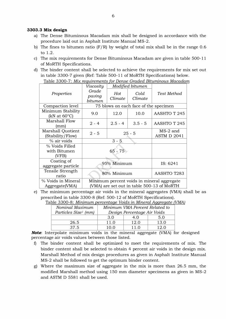
6
3303.3 Mix design
a) The Dense Bituminous Macadam mix shall be designed in accordance with the
procedure laid out in Asphalt Institute Manual MS-2.
b) The fines to bitumen ratio (F/R) by weight of total mix shall be in the range 0.6
to 1.2.
c) The mix requirements for Dense Bituminous Macadam are given in table 500-11
of MoRTH Specifications.
d) The binder content shall be selected to achieve the requirements for mix set out
in table 3300-7 given (Ref: Table 500-11 of MoRTH Specifications) below.
Table 3300-7: Mix requirements for Dense Graded Bituminous Macadam
Properties
Viscosity Grade paving
bitumen
Modified bitumen
Test Method Hot Climate
Cold Climate
Compaction level 75 blows on each face of the specimen
Minimum Stability (kN at 60°C)
9.0 12.0 10.0 AASHTO T 245
Marshall Flow (mm)
2 - 4 2.5 - 4 3.5 - 5 AASHTO T 245
Marshall Quotient (Stability/Flow)
2 - 5 25 - 5 MS-2 and
ASTM D 2041
% air voids 3 - 5
% Voids Filled with Bitumen
(VFB) 65 - 75
Coating of aggregate particle
95% Minimum IS: 6241
Tensile Strength ratio
80% Minimum AASHTO T283
% Voids in Mineral Aggregate(VMA)
Minimum percent voids in mineral aggregate (VMA) are set out in table 500-13 of MoRTH
e) The minimum percentage air voids in the mineral aggregates (VMA) shall be as
prescribed in table 3300-8 (Ref: 500-12 of MoRTH Specifications). Table 3300-8: Minimum percentage Voids in Mineral Aggregate (VMA)
Nominal Maximum Particles Size1 (mm)
Minimum VMA Percent Related to Design Percentage Air Voids
3.0 4.0 5.0
26.5 11.0 12.0 13.0
37.5 10.0 11.0 12.0
Note: Interpolate minimum voids in the mineral aggregate (VMA) for designed percentage air voids values between those listed.
f) The binder content shall be optimized to meet the requirements of mix. The
binder content shall be selected to obtain 4 percent air voids in the design mix.
Marshall Method of mix design procedures as given in Asphalt Institute Manual
MS-2 shall be followed to get the optimum binder content.
g) Where the maximum size of aggregate in the mix is more than 26.5 mm, the
modified Marshall method using 150 mm diameter specimens as given in MS-2
and ASTM D 5581 shall be used.

7
3303.4 Job mix formula
The job mix formula to be used in the work shall be proposed by the Contractor 21
days before the start of the work. The following details shall be included in the report
accompanying the job mix formula.
a) Source and location of all materials.
b) Binder type and percentage by weight of total mix.
c) Proportion of various coarse and fine aggregates including filler by weight of
total aggregate mix.
d) A single definite percentage passing each sieve for the aggregate mix.
e) Grading of the individual aggregates including filler.
f) Where batch mixing is adopted weight of each fraction of aggregate and binder
per batch.
g) Test results of the physical properties of the aggregates to be used in the work.
h) Test results of the volumetric analysis of the mix such as maximum specific
gravity of the loose mix (Gmm), densities of the compacted specimens for various
binder contents, Voids in mineral aggregates (VMA), air voids in the compacted
mix (Va), Voids filled with bitumen (VFB).
i) Reports on the Marshall test viz., Stability & flow.
j) Mixing temperature and compacting temperature.
k) Marshall design curves showing Stability, Flow, Density, Air voids, VMA and
VFB plotted against different binder contents.
3303.5 Approval of the job mix formula
a) Approval of the job mix formula shall be given by the Engineer after conducting
necessary acceptance tests using the samples of materials proposed to be used
in the work.
b) A revised mix design shall be carried out and a new job mix formula approved
once a change in source of the material is required.
3303.6 Plant and field trials
a) After approval of the job mix formula, plant trials must be carried out to
establish that a uniform mix is produced and the variations of individual
fractions are within the permitted tolerance specified in table 3300-9 (Ref: Table
500-13 of MoRTH specifications) below.
Table 3300-9: Permissible variations in the actual mix from the Job Mix Formula
Description Base/binder course
Aggregate passing 19 mm sieve or larger ± 8%
Aggregate passing 13.2 mm,9.5 mm ± 7%
Aggregate passing 4.75 mm ± 6%
Aggregate passing 2.36 mm, 1.18 mm, 0.600 mm ± 5%
Aggregate passing 0.300 mm, 0.150 mm ± 4%
Aggregate passing 0.075 mm ± 2%
Binder content ± 0.3%
Mixing temperature ± 100C
b) After the successful completion of plant trials, field trials are carried out.
c) The field trials will establish if the paving machineries and procedures are
sufficient to produce a satisfactory pavement layer.
d) Density of the finished paving shall be determined by taking cores no sooner
than 24 hours after finishing the layer.
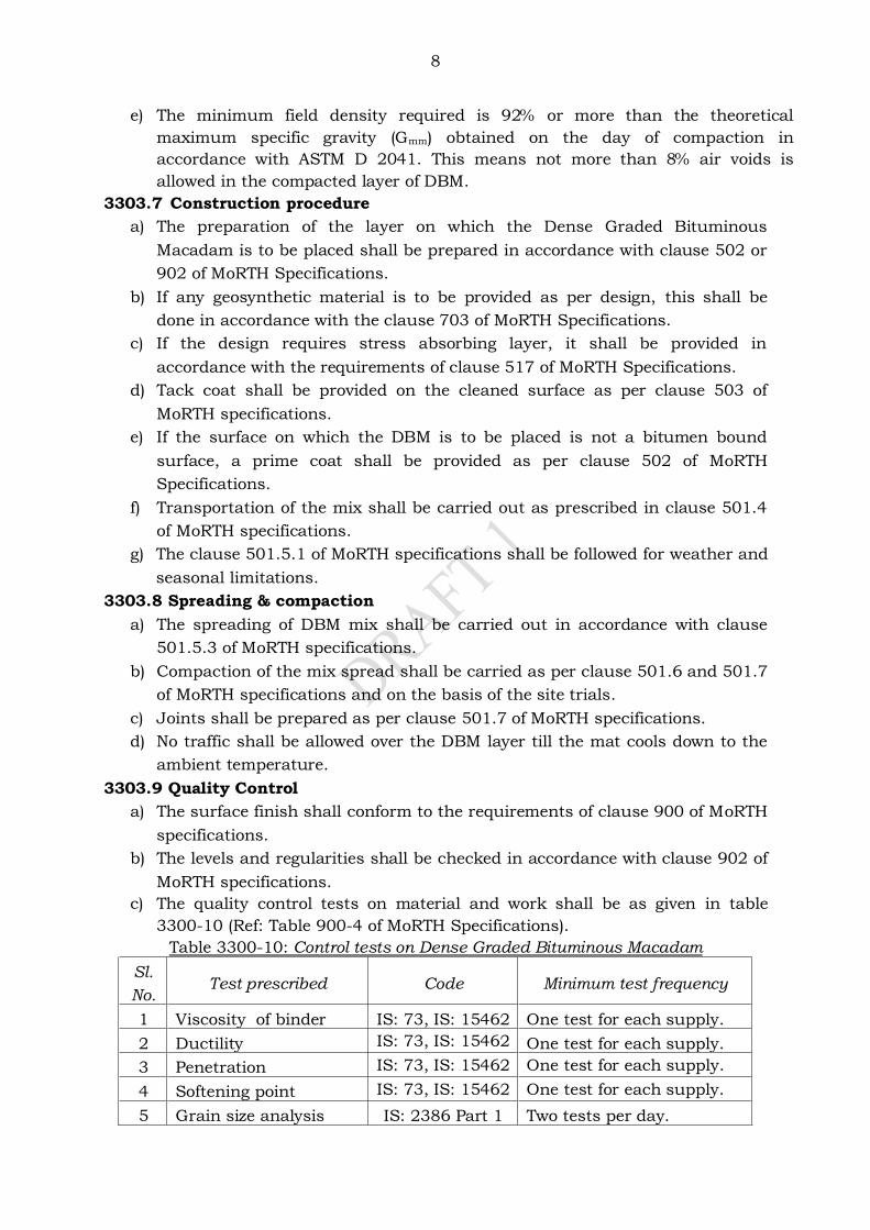
8
e) The minimum field density required is 92% or more than the theoretical
maximum specific gravity (Gmm) obtained on the day of compaction in
accordance with ASTM D 2041. This means not more than 8% air voids is
allowed in the compacted layer of DBM.
3303.7 Construction procedure
a) The preparation of the layer on which the Dense Graded Bituminous
Macadam is to be placed shall be prepared in accordance with clause 502 or
902 of MoRTH Specifications.
b) If any geosynthetic material is to be provided as per design, this shall be
done in accordance with the clause 703 of MoRTH Specifications.
c) If the design requires stress absorbing layer, it shall be provided in
accordance with the requirements of clause 517 of MoRTH Specifications.
d) Tack coat shall be provided on the cleaned surface as per clause 503 of
MoRTH specifications.
e) If the surface on which the DBM is to be placed is not a bitumen bound
surface, a prime coat shall be provided as per clause 502 of MoRTH
Specifications.
f) Transportation of the mix shall be carried out as prescribed in clause 501.4
of MoRTH specifications.
g) The clause 501.5.1 of MoRTH specifications shall be followed for weather and
seasonal limitations.
3303.8 Spreading & compaction
a) The spreading of DBM mix shall be carried out in accordance with clause
501.5.3 of MoRTH specifications.
b) Compaction of the mix spread shall be carried as per clause 501.6 and 501.7
of MoRTH specifications and on the basis of the site trials.
c) Joints shall be prepared as per clause 501.7 of MoRTH specifications.
d) No traffic shall be allowed over the DBM layer till the mat cools down to the
ambient temperature.
3303.9 Quality Control
a) The surface finish shall conform to the requirements of clause 900 of MoRTH
specifications.
b) The levels and regularities shall be checked in accordance with clause 902 of
MoRTH specifications.
c) The quality control tests on material and work shall be as given in table
3300-10 (Ref: Table 900-4 of MoRTH Specifications).
Table 3300-10: Control tests on Dense Graded Bituminous Macadam
Sl.
No. Test prescribed Code Minimum test frequency
1 Viscosity of binder IS: 73, IS: 15462 One test for each supply.
2 Ductility IS: 73, IS: 15462 One test for each supply.
3 Penetration IS: 73, IS: 15462 One test for each supply.
4 Softening point IS: 73, IS: 15462 One test for each supply.
5 Grain size analysis IS: 2386 Part 1 Two tests per day.
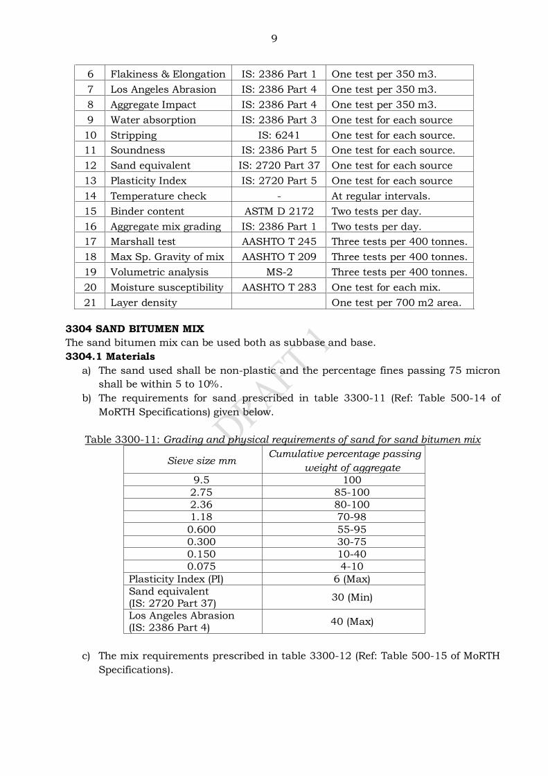
9
6 Flakiness & Elongation IS: 2386 Part 1 One test per 350 m3.
7 Los Angeles Abrasion IS: 2386 Part 4 One test per 350 m3.
8 Aggregate Impact IS: 2386 Part 4 One test per 350 m3.
9 Water absorption IS: 2386 Part 3 One test for each source
10 Stripping IS: 6241 One test for each source.
11 Soundness IS: 2386 Part 5 One test for each source.
12 Sand equivalent IS: 2720 Part 37 One test for each source
13 Plasticity Index IS: 2720 Part 5 One test for each source
14 Temperature check - At regular intervals.
15 Binder content ASTM D 2172 Two tests per day.
16 Aggregate mix grading IS: 2386 Part 1 Two tests per day.
17 Marshall test AASHTO T 245 Three tests per 400 tonnes.
18 Max Sp. Gravity of mix AASHTO T 209 Three tests per 400 tonnes.
19 Volumetric analysis MS-2 Three tests per 400 tonnes.
20 Moisture susceptibility AASHTO T 283 One test for each mix.
21 Layer density One test per 700 m2 area.
3304 SAND BITUMEN MIX
The sand bitumen mix can be used both as subbase and base.
3304.1 Materials
a) The sand used shall be non-plastic and the percentage fines passing 75 micron
shall be within 5 to 10%.
b) The requirements for sand prescribed in table 3300-11 (Ref: Table 500-14 of
MoRTH Specifications) given below.
Table 3300-11: Grading and physical requirements of sand for sand bitumen mix
Sieve size mm Cumulative percentage passing by
weight of aggregate
9.5 100
2.75 85-100
2.36 80-100
1.18 70-98
0.600 55-95
0.300 30-75
0.150 10-40
0.075 4-10
Plasticity Index (PI) 6 (Max)
Sand equivalent (IS: 2720 Part 37)
30 (Min)
Los Angeles Abrasion (IS: 2386 Part 4)
40 (Max)
c) The mix requirements prescribed in table 3300-12 (Ref: Table 500-15 of MoRTH
Specifications).
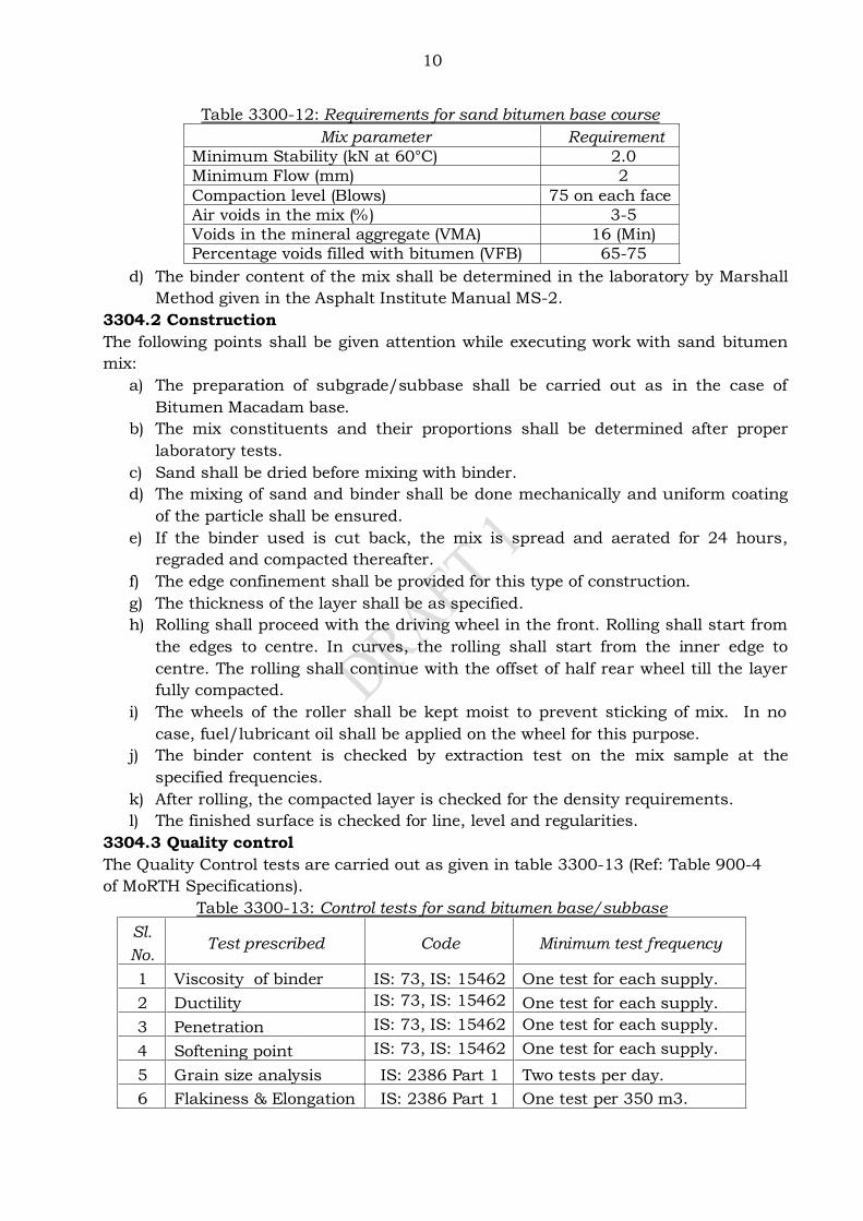
10
Table 3300-12: Requirements for sand bitumen base course
Mix parameter Requirement
Minimum Stability (kN at 60°C) 2.0
Minimum Flow (mm) 2
Compaction level (Blows) 75 on each face
Air voids in the mix (%) 3-5
Voids in the mineral aggregate (VMA) 16 (Min)
Percentage voids filled with bitumen (VFB) 65-75
d) The binder content of the mix shall be determined in the laboratory by Marshall
Method given in the Asphalt Institute Manual MS-2.
3304.2 Construction
The following points shall be given attention while executing work with sand bitumen
mix:
a) The preparation of subgrade/subbase shall be carried out as in the case of
Bitumen Macadam base.
b) The mix constituents and their proportions shall be determined after proper
laboratory tests.
c) Sand shall be dried before mixing with binder.
d) The mixing of sand and binder shall be done mechanically and uniform coating
of the particle shall be ensured.
e) If the binder used is cut back, the mix is spread and aerated for 24 hours,
regraded and compacted thereafter.
f) The edge confinement shall be provided for this type of construction.
g) The thickness of the layer shall be as specified.
h) Rolling shall proceed with the driving wheel in the front. Rolling shall start from
the edges to centre. In curves, the rolling shall start from the inner edge to
centre. The rolling shall continue with the offset of half rear wheel till the layer
fully compacted.
i) The wheels of the roller shall be kept moist to prevent sticking of mix. In no
case, fuel/lubricant oil shall be applied on the wheel for this purpose.
j) The binder content is checked by extraction test on the mix sample at the
specified frequencies.
k) After rolling, the compacted layer is checked for the density requirements.
l) The finished surface is checked for line, level and regularities.
3304.3 Quality control
The Quality Control tests are carried out as given in table 3300-13 (Ref: Table 900-4
of MoRTH Specifications).
Table 3300-13: Control tests for sand bitumen base/subbase
Sl.
No. Test prescribed Code Minimum test frequency
1 Viscosity of binder IS: 73, IS: 15462 One test for each supply.
2 Ductility IS: 73, IS: 15462 One test for each supply.
3 Penetration IS: 73, IS: 15462 One test for each supply.
4 Softening point IS: 73, IS: 15462 One test for each supply.
5 Grain size analysis IS: 2386 Part 1 Two tests per day.
6 Flakiness & Elongation IS: 2386 Part 1 One test per 350 m3.
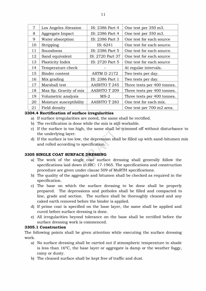
11
7 Los Angeles Abrasion IS: 2386 Part 4 One test per 350 m3.
8 Aggregate Impact IS: 2386 Part 4 One test per 350 m3.
9 Water absorption IS: 2386 Part 3 One test for each source
10 Stripping IS: 6241 One test for each source.
11 Soundness IS: 2386 Part 5 One test for each source.
12 Sand equivalent IS: 2720 Part 37 One test for each source
13 Plasticity Index IS: 2720 Part 5 One test for each source
14 Temperature check - At regular intervals.
15 Binder content ASTM D 2172 Two tests per day.
16 Mix grading IS: 2386 Part 1 Two tests per day.
17 Marshall test AASHTO T 245 Three tests per 400 tonnes.
18 Max Sp. Gravity of mix AASHTO T 209 Three tests per 400 tonnes.
19 Volumetric analysis MS-2 Three tests per 400 tonnes.
20 Moisture susceptibility AASHTO T 283 One test for each mix.
21 Field density One test per 700 m2 area.
3304.4 Rectification of surface irregularities
a) If surface irregularities are noted, the same shall be rectified.
b) The rectification is done while the mix is still workable.
c) If the surface is too high, the same shall be trimmed off without disturbance to
the underlying layer.
d) If the surface is too low, the depression shall be filled up with sand-bitumen mix
and rolled according to specification.
3305 SINGLE COAT SURFACE DRESSING
a) The work of the single coat surface dressing shall generally follow the
specifications laid down in IRC: 17-1965. The specifications and construction
procedure are given under clause 509 of MoRTH specifications.
b) The quality of the aggregate and bitumen shall be checked as required in the
specification.
c) The base on which the surface dressing to be done shall be properly
prepared. The depressions and potholes shall be filled and compacted to
line, grade and section. The surface shall be thoroughly cleaned and any
caked earth removed before the binder is applied.
d) If prime coat is specified on the base layer, the same shall be applied and
cured before surface dressing is done.
e) All irregularities beyond tolerance on the base shall be rectified before the
surface dressing work is commenced.
3305.1 Construction
The following points shall be given attention while executing the surface dressing
work.
a) No surface dressing shall be carried out if atmospheric temperature in shade
is less than 16°C, the base layer or aggregate is damp or the weather foggy,
rainy or dusty.
b) The cleaned surface shall be kept free of traffic and dust.
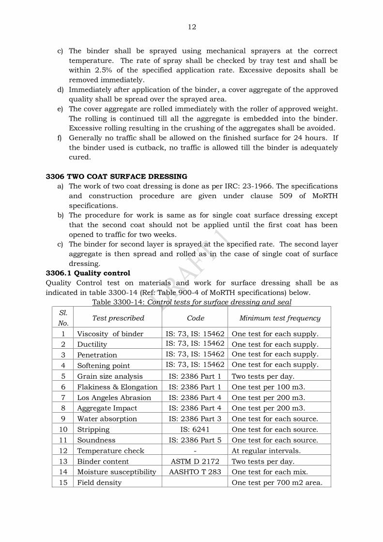
12
c) The binder shall be sprayed using mechanical sprayers at the correct
temperature. The rate of spray shall be checked by tray test and shall be
within 2.5% of the specified application rate. Excessive deposits shall be
removed immediately.
d) Immediately after application of the binder, a cover aggregate of the approved
quality shall be spread over the sprayed area.
e) The cover aggregate are rolled immediately with the roller of approved weight.
The rolling is continued till all the aggregate is embedded into the binder.
Excessive rolling resulting in the crushing of the aggregates shall be avoided.
f) Generally no traffic shall be allowed on the finished surface for 24 hours. If
the binder used is cutback, no traffic is allowed till the binder is adequately
cured.
3306 TWO COAT SURFACE DRESSING
a) The work of two coat dressing is done as per IRC: 23-1966. The specifications
and construction procedure are given under clause 509 of MoRTH
specifications.
b) The procedure for work is same as for single coat surface dressing except
that the second coat should not be applied until the first coat has been
opened to traffic for two weeks.
c) The binder for second layer is sprayed at the specified rate. The second layer
aggregate is then spread and rolled as in the case of single coat of surface
dressing.
3306.1 Quality control
Quality Control test on materials and work for surface dressing shall be as
indicated in table 3300-14 (Ref: Table 900-4 of MoRTH specifications) below.
Table 3300-14: Control tests for surface dressing and seal
Sl.
No. Test prescribed Code Minimum test frequency
1 Viscosity of binder IS: 73, IS: 15462 One test for each supply.
2 Ductility IS: 73, IS: 15462 One test for each supply.
3 Penetration IS: 73, IS: 15462 One test for each supply.
4 Softening point IS: 73, IS: 15462 One test for each supply.
5 Grain size analysis IS: 2386 Part 1 Two tests per day.
6 Flakiness & Elongation IS: 2386 Part 1 One test per 100 m3.
7 Los Angeles Abrasion IS: 2386 Part 4 One test per 200 m3.
8 Aggregate Impact IS: 2386 Part 4 One test per 200 m3.
9 Water absorption IS: 2386 Part 3 One test for each source.
10 Stripping IS: 6241 One test for each source.
11 Soundness IS: 2386 Part 5 One test for each source.
12 Temperature check - At regular intervals.
13 Binder content ASTM D 2172 Two tests per day.
14 Moisture susceptibility AASHTO T 283 One test for each mix.
15 Field density One test per 700 m2 area.
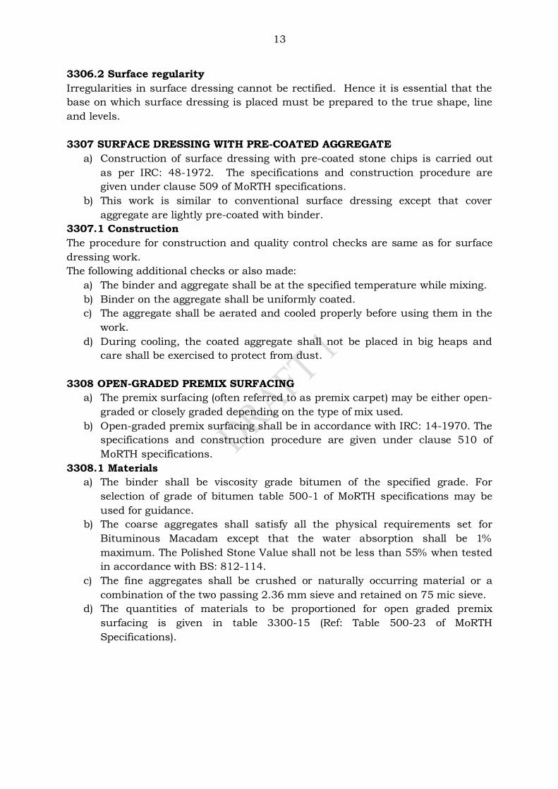
13
3306.2 Surface regularity
Irregularities in surface dressing cannot be rectified. Hence it is essential that the
base on which surface dressing is placed must be prepared to the true shape, line
and levels.
3307 SURFACE DRESSING WITH PRE-COATED AGGREGATE
a) Construction of surface dressing with pre-coated stone chips is carried out
as per IRC: 48-1972. The specifications and construction procedure are
given under clause 509 of MoRTH specifications.
b) This work is similar to conventional surface dressing except that cover
aggregate are lightly pre-coated with binder.
3307.1 Construction
The procedure for construction and quality control checks are same as for surface
dressing work.
The following additional checks or also made:
a) The binder and aggregate shall be at the specified temperature while mixing.
b) Binder on the aggregate shall be uniformly coated.
c) The aggregate shall be aerated and cooled properly before using them in the
work.
d) During cooling, the coated aggregate shall not be placed in big heaps and
care shall be exercised to protect from dust.
3308 OPEN-GRADED PREMIX SURFACING
a) The premix surfacing (often referred to as premix carpet) may be either open-
graded or closely graded depending on the type of mix used.
b) Open-graded premix surfacing shall be in accordance with IRC: 14-1970. The
specifications and construction procedure are given under clause 510 of
MoRTH specifications.
3308.1 Materials
a) The binder shall be viscosity grade bitumen of the specified grade. For
selection of grade of bitumen table 500-1 of MoRTH specifications may be
used for guidance.
b) The coarse aggregates shall satisfy all the physical requirements set for
Bituminous Macadam except that the water absorption shall be 1%
maximum. The Polished Stone Value shall not be less than 55% when tested
in accordance with BS: 812-114.
c) The fine aggregates shall be crushed or naturally occurring material or a
combination of the two passing 2.36 mm sieve and retained on 75 mic sieve.
d) The quantities of materials to be proportioned for open graded premix
surfacing is given in table 3300-15 (Ref: Table 500-23 of MoRTH
Specifications).
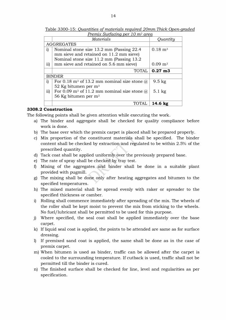
14
Table 3300-15: Quantities of materials required 20mm Thick Open-graded Premix Surfacing per 10 m2 area
Materials Quantity
AGGREGATES
i) ii)
Nominal stone size 13.2 mm (Passing 22.4 mm sieve and retained on 11.2 mm sieve) Nominal stone size 11.2 mm (Passing 13.2 mm sieve and retained on 5.6 mm sieve)
0.18 m3
0.09 m3
TOTAL 0.27 m3
BINDER
i) ii)
For 0.18 m3 of 13.2 mm nominal size stone @ 52 Kg bitumen per m3
For 0.09 m3 of 11.2 mm nominal size stone @ 56 Kg bitumen per m3
9.5 kg 5.1 kg
TOTAL 14.6 kg
3308.2 Construction
The following points shall be given attention while executing the work.
a) The binder and aggregate shall be checked for quality compliance before
work is done.
b) The base over which the premix carpet is placed shall be prepared properly.
c) Mix proportion of the constituent materials shall be specified. The binder
content shall be checked by extraction and regulated to be within 2.5% of the
prescribed quantity.
d) Tack coat shall be applied uniformly over the previously prepared base.
e) The rate of spray shall be checked by tray test.
f) Mixing of the aggregates and binder shall be done in a suitable plant
provided with pugmill.
g) The mixing shall be done only after heating aggregates and bitumen to the
specified temperatures.
h) The mixed material shall be spread evenly with raker or spreader to the
specified thickness or camber.
i) Rolling shall commence immediately after spreading of the mix. The wheels of
the roller shall be kept moist to prevent the mix from sticking to the wheels.
No fuel/lubricant shall be permitted to be used for this purpose.
j) Where specified, the seal coat shall be applied immediately over the base
carpet.
k) If liquid seal coat is applied, the points to be attended are same as for surface
dressing.
l) If premixed sand coat is applied, the same shall be done as in the case of
premix carpet.
m) When bitumen is used as binder, traffic can be allowed after the carpet is
cooled to the surrounding temperature. If cutback is used, traffic shall not be
permitted till the binder is cured.
n) The finished surface shall be checked for line, level and regularities as per
specification.
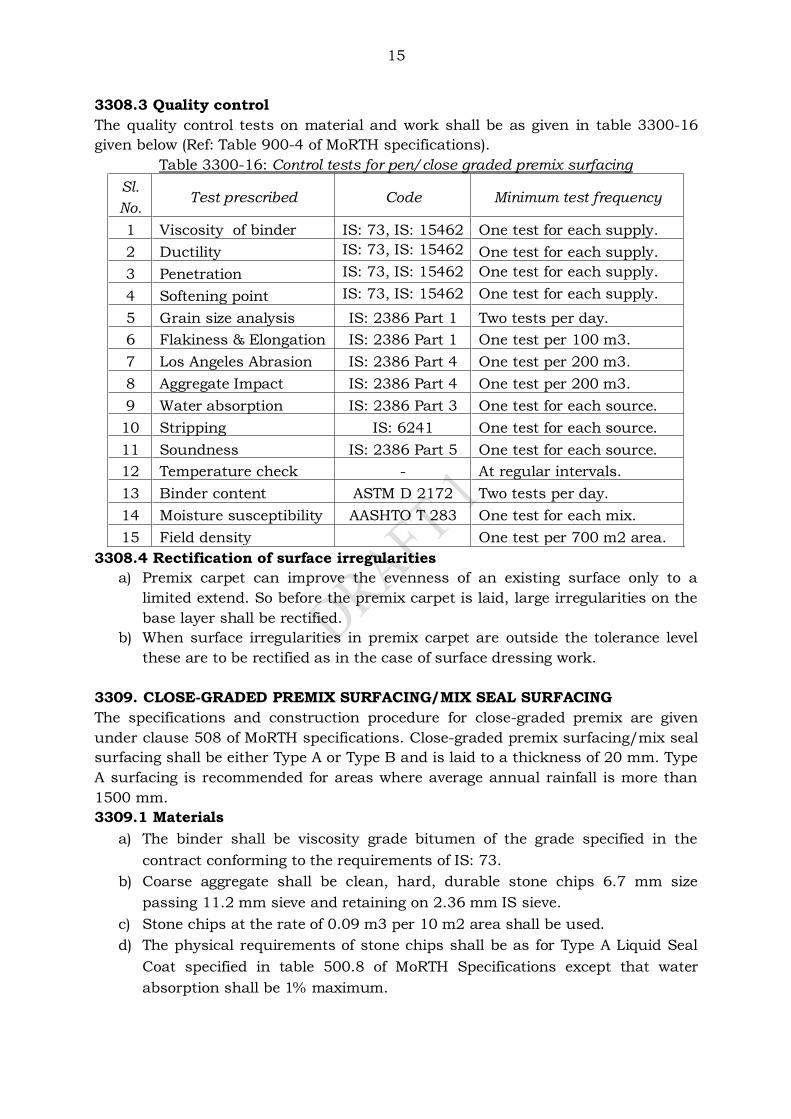
15
3308.3 Quality control
The quality control tests on material and work shall be as given in table 3300-16
given below (Ref: Table 900-4 of MoRTH specifications).
Table 3300-16: Control tests for pen/close graded premix surfacing
Sl.
No. Test prescribed Code Minimum test frequency
1 Viscosity of binder IS: 73, IS: 15462 One test for each supply.
2 Ductility IS: 73, IS: 15462 One test for each supply.
3 Penetration IS: 73, IS: 15462 One test for each supply.
4 Softening point IS: 73, IS: 15462 One test for each supply.
5 Grain size analysis IS: 2386 Part 1 Two tests per day.
6 Flakiness & Elongation IS: 2386 Part 1 One test per 100 m3.
7 Los Angeles Abrasion IS: 2386 Part 4 One test per 200 m3.
8 Aggregate Impact IS: 2386 Part 4 One test per 200 m3.
9 Water absorption IS: 2386 Part 3 One test for each source.
10 Stripping IS: 6241 One test for each source.
11 Soundness IS: 2386 Part 5 One test for each source.
12 Temperature check - At regular intervals.
13 Binder content ASTM D 2172 Two tests per day.
14 Moisture susceptibility AASHTO T 283 One test for each mix.
15 Field density One test per 700 m2 area.
3308.4 Rectification of surface irregularities
a) Premix carpet can improve the evenness of an existing surface only to a
limited extend. So before the premix carpet is laid, large irregularities on the
base layer shall be rectified.
b) When surface irregularities in premix carpet are outside the tolerance level
these are to be rectified as in the case of surface dressing work.
3309. CLOSE-GRADED PREMIX SURFACING/MIX SEAL SURFACING
The specifications and construction procedure for close-graded premix are given
under clause 508 of MoRTH specifications. Close-graded premix surfacing/mix seal
surfacing shall be either Type A or Type B and is laid to a thickness of 20 mm. Type
A surfacing is recommended for areas where average annual rainfall is more than
1500 mm.
3309.1 Materials
a) The binder shall be viscosity grade bitumen of the grade specified in the
contract conforming to the requirements of IS: 73.
b) Coarse aggregate shall be clean, hard, durable stone chips 6.7 mm size
passing 11.2 mm sieve and retaining on 2.36 mm IS sieve.
c) Stone chips at the rate of 0.09 m3 per 10 m2 area shall be used.
d) The physical requirements of stone chips shall be as for Type A Liquid Seal
Coat specified in table 500.8 of MoRTH Specifications except that water
absorption shall be 1% maximum.
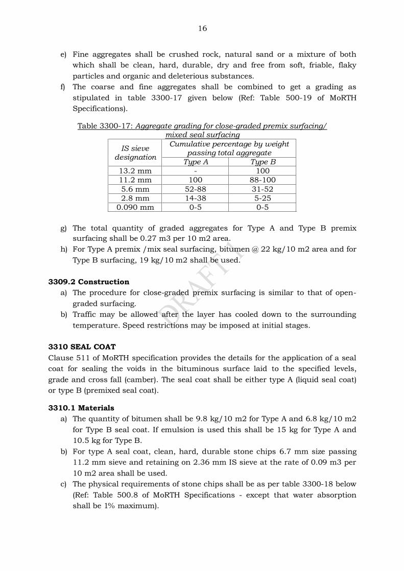
16
e) Fine aggregates shall be crushed rock, natural sand or a mixture of both
which shall be clean, hard, durable, dry and free from soft, friable, flaky
particles and organic and deleterious substances.
f) The coarse and fine aggregates shall be combined to get a grading as
stipulated in table 3300-17 given below (Ref: Table 500-19 of MoRTH
Specifications).
Table 3300-17: Aggregate grading for close-graded premix surfacing/ mixed seal surfacing
g) The total quantity of graded aggregates for Type A and Type B premix
surfacing shall be 0.27 m3 per 10 m2 area.
h) For Type A premix /mix seal surfacing, bitumen @ 22 kg/10 m2 area and for
Type B surfacing, 19 kg/10 m2 shall be used.
3309.2 Construction
a) The procedure for close-graded premix surfacing is similar to that of open-
graded surfacing.
b) Traffic may be allowed after the layer has cooled down to the surrounding
temperature. Speed restrictions may be imposed at initial stages.
3310 SEAL COAT
Clause 511 of MoRTH specification provides the details for the application of a seal
coat for sealing the voids in the bituminous surface laid to the specified levels,
grade and cross fall (camber). The seal coat shall be either type A (liquid seal coat)
or type B (premixed seal coat). 3310.1 Materials
a) The quantity of bitumen shall be 9.8 kg/10 m2 for Type A and 6.8 kg/10 m2
for Type B seal coat. If emulsion is used this shall be 15 kg for Type A and
10.5 kg for Type B.
b) For type A seal coat, clean, hard, durable stone chips 6.7 mm size passing
11.2 mm sieve and retaining on 2.36 mm IS sieve at the rate of 0.09 m3 per
10 m2 area shall be used.
c) The physical requirements of stone chips shall be as per table 3300-18 below
(Ref: Table 500.8 of MoRTH Specifications - except that water absorption
shall be 1% maximum).
IS sieve designation
Cumulative percentage by weight passing total aggregate
Type A Type B
13.2 mm - 100
11.2 mm 100 88-100
5.6 mm 52-88 31-52
2.8 mm 14-38 5-25
0.090 mm 0-5 0-5
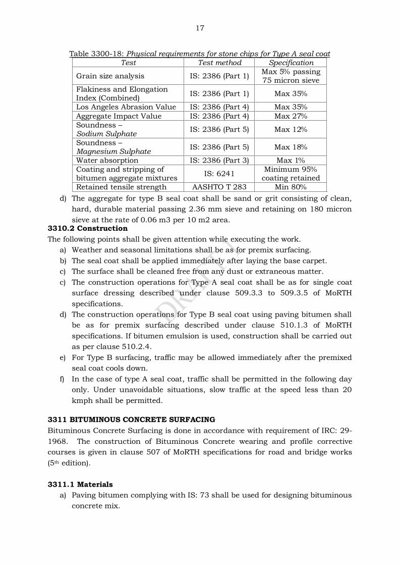
17
Table 3300-18: Physical requirements for stone chips for Type A seal coat
Test Test method Specification
Grain size analysis IS: 2386 (Part 1) Max 5% passing 75 micron sieve
Flakiness and Elongation Index (Combined)
IS: 2386 (Part 1) Max 35%
Los Angeles Abrasion Value IS: 2386 (Part 4) Max 35%
Aggregate Impact Value IS: 2386 (Part 4) Max 27%
Soundness – Sodium Sulphate
IS: 2386 (Part 5) Max 12%
Soundness – Magnesium Sulphate
IS: 2386 (Part 5) Max 18%
Water absorption IS: 2386 (Part 3) Max 1%
Coating and stripping of bitumen aggregate mixtures
IS: 6241 Minimum 95%
coating retained
Retained tensile strength AASHTO T 283 Min 80%
d) The aggregate for type B seal coat shall be sand or grit consisting of clean,
hard, durable material passing 2.36 mm sieve and retaining on 180 micron
sieve at the rate of 0.06 m3 per 10 m2 area. 3310.2 Construction
The following points shall be given attention while executing the work.
a) Weather and seasonal limitations shall be as for premix surfacing.
b) The seal coat shall be applied immediately after laying the base carpet.
c) The surface shall be cleaned free from any dust or extraneous matter.
c) The construction operations for Type A seal coat shall be as for single coat
surface dressing described under clause 509.3.3 to 509.3.5 of MoRTH
specifications.
d) The construction operations for Type B seal coat using paving bitumen shall
be as for premix surfacing described under clause 510.1.3 of MoRTH
specifications. If bitumen emulsion is used, construction shall be carried out
as per clause 510.2.4.
e) For Type B surfacing, traffic may be allowed immediately after the premixed
seal coat cools down.
f) In the case of type A seal coat, traffic shall be permitted in the following day
only. Under unavoidable situations, slow traffic at the speed less than 20
kmph shall be permitted.
3311 BITUMINOUS CONCRETE SURFACING
Bituminous Concrete Surfacing is done in accordance with requirement of IRC: 29-
1968. The construction of Bituminous Concrete wearing and profile corrective
courses is given in clause 507 of MoRTH specifications for road and bridge works
(5th edition).
3311.1 Materials
a) Paving bitumen complying with IS: 73 shall be used for designing bituminous
concrete mix.
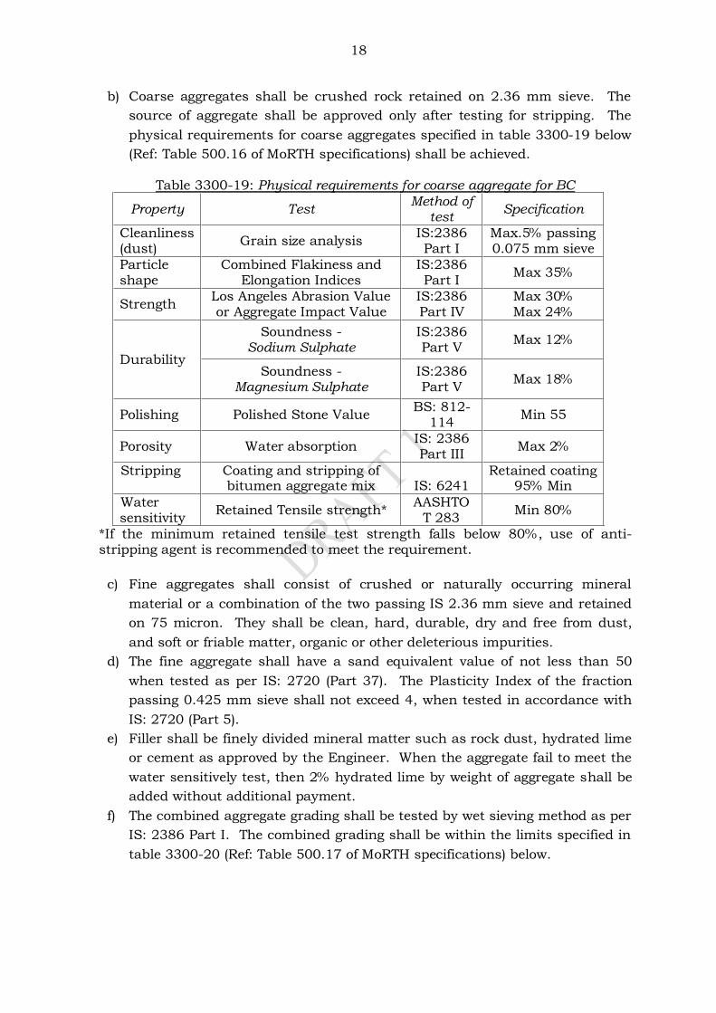
18
b) Coarse aggregates shall be crushed rock retained on 2.36 mm sieve. The
source of aggregate shall be approved only after testing for stripping. The
physical requirements for coarse aggregates specified in table 3300-19 below
(Ref: Table 500.16 of MoRTH specifications) shall be achieved.
Table 3300-19: Physical requirements for coarse aggregate for BC
Property Test Method of
test Specification
Cleanliness (dust)
Grain size analysis IS:2386 Part I
Max.5% passing 0.075 mm sieve
Particle shape
Combined Flakiness and Elongation Indices
IS:2386 Part I
Max 35%
Strength Los Angeles Abrasion Value or Aggregate Impact Value
IS:2386 Part IV
Max 30% Max 24%
Durability
Soundness - Sodium Sulphate
IS:2386 Part V
Max 12%
Soundness - Magnesium Sulphate
IS:2386 Part V
Max 18%
Polishing Polished Stone Value BS: 812-
114 Min 55
Porosity Water absorption IS: 2386 Part III
Max 2%
Stripping
Coating and stripping of bitumen aggregate mix
IS: 6241
Retained coating 95% Min
Water sensitivity
Retained Tensile strength* AASHTO
T 283 Min 80%
*If the minimum retained tensile test strength falls below 80%, use of anti-stripping agent is recommended to meet the requirement.
c) Fine aggregates shall consist of crushed or naturally occurring mineral
material or a combination of the two passing IS 2.36 mm sieve and retained
on 75 micron. They shall be clean, hard, durable, dry and free from dust,
and soft or friable matter, organic or other deleterious impurities.
d) The fine aggregate shall have a sand equivalent value of not less than 50
when tested as per IS: 2720 (Part 37). The Plasticity Index of the fraction
passing 0.425 mm sieve shall not exceed 4, when tested in accordance with
IS: 2720 (Part 5).
e) Filler shall be finely divided mineral matter such as rock dust, hydrated lime
or cement as approved by the Engineer. When the aggregate fail to meet the
water sensitively test, then 2% hydrated lime by weight of aggregate shall be
added without additional payment.
f) The combined aggregate grading shall be tested by wet sieving method as per
IS: 2386 Part I. The combined grading shall be within the limits specified in
table 3300-20 (Ref: Table 500.17 of MoRTH specifications) below.
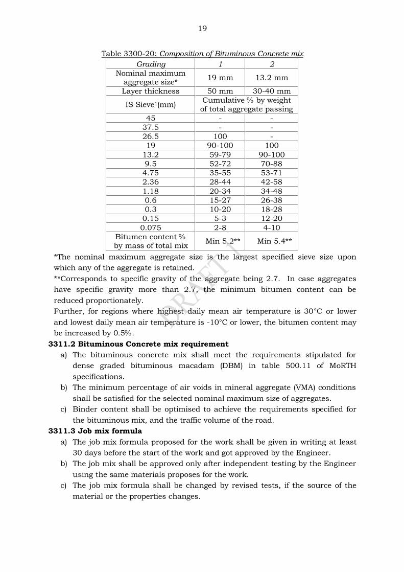
19
Table 3300-20: Composition of Bituminous Concrete mix
Grading 1 2
Nominal maximum aggregate size*
19 mm 13.2 mm
Layer thickness 50 mm 30-40 mm
IS Sieve1(mm) Cumulative % by weight of total aggregate passing
45 - -
37.5 - -
26.5 100 -
19 90-100 100
13.2 59-79 90-100
9.5 52-72 70-88
4.75 35-55 53-71
2.36 28-44 42-58
1.18 20-34 34-48
0.6 15-27 26-38
0.3 10-20 18-28
0.15 5-3 12-20
0.075 2-8 4-10
Bitumen content % by mass of total mix
Min 5.2** Min 5.4**
*The nominal maximum aggregate size is the largest specified sieve size upon
which any of the aggregate is retained.
**Corresponds to specific gravity of the aggregate being 2.7. In case aggregates
have specific gravity more than 2.7, the minimum bitumen content can be
reduced proportionately.
Further, for regions where highest daily mean air temperature is 30°C or lower
and lowest daily mean air temperature is -10°C or lower, the bitumen content may
be increased by 0.5%.
3311.2 Bituminous Concrete mix requirement
a) The bituminous concrete mix shall meet the requirements stipulated for
dense graded bituminous macadam (DBM) in table 500.11 of MoRTH
specifications.
b) The minimum percentage of air voids in mineral aggregate (VMA) conditions
shall be satisfied for the selected nominal maximum size of aggregates.
c) Binder content shall be optimised to achieve the requirements specified for
the bituminous mix, and the traffic volume of the road.
3311.3 Job mix formula
a) The job mix formula proposed for the work shall be given in writing at least
30 days before the start of the work and got approved by the Engineer.
b) The job mix shall be approved only after independent testing by the Engineer
using the same materials proposes for the work.
c) The job mix formula shall be changed by revised tests, if the source of the
material or the properties changes.
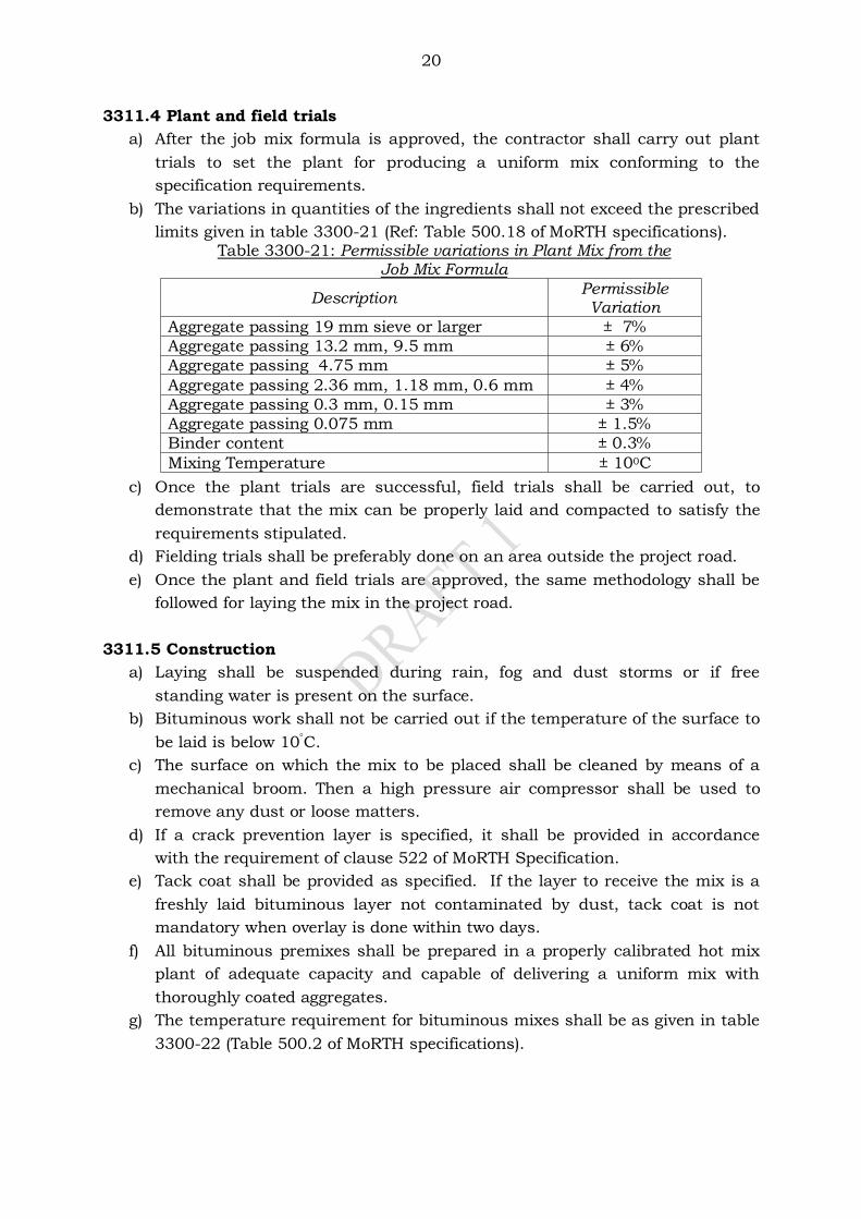
20
3311.4 Plant and field trials
a) After the job mix formula is approved, the contractor shall carry out plant
trials to set the plant for producing a uniform mix conforming to the
specification requirements.
b) The variations in quantities of the ingredients shall not exceed the prescribed
limits given in table 3300-21 (Ref: Table 500.18 of MoRTH specifications). Table 3300-21: Permissible variations in Plant Mix from the
Job Mix Formula
Description Permissible Variation
Aggregate passing 19 mm sieve or larger ± 7%
Aggregate passing 13.2 mm, 9.5 mm ± 6%
Aggregate passing 4.75 mm ± 5%
Aggregate passing 2.36 mm, 1.18 mm, 0.6 mm ± 4%
Aggregate passing 0.3 mm, 0.15 mm ± 3%
Aggregate passing 0.075 mm ± 1.5%
Binder content ± 0.3%
Mixing Temperature ± 100C
c) Once the plant trials are successful, field trials shall be carried out, to
demonstrate that the mix can be properly laid and compacted to satisfy the
requirements stipulated.
d) Fielding trials shall be preferably done on an area outside the project road.
e) Once the plant and field trials are approved, the same methodology shall be
followed for laying the mix in the project road.
3311.5 Construction
a) Laying shall be suspended during rain, fog and dust storms or if free
standing water is present on the surface.
b) Bituminous work shall not be carried out if the temperature of the surface to
be laid is below 10C.
c) The surface on which the mix to be placed shall be cleaned by means of a
mechanical broom. Then a high pressure air compressor shall be used to
remove any dust or loose matters.
d) If a crack prevention layer is specified, it shall be provided in accordance
with the requirement of clause 522 of MoRTH Specification.
e) Tack coat shall be provided as specified. If the layer to receive the mix is a
freshly laid bituminous layer not contaminated by dust, tack coat is not
mandatory when overlay is done within two days.
f) All bituminous premixes shall be prepared in a properly calibrated hot mix
plant of adequate capacity and capable of delivering a uniform mix with
thoroughly coated aggregates.
g) The temperature requirement for bituminous mixes shall be as given in table
3300-22 (Table 500.2 of MoRTH specifications).
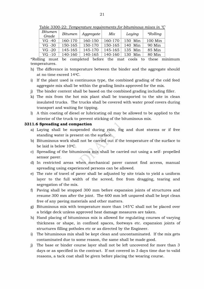
21
Table 3300-22: Temperature requirements for bituminous mixes in °C
Bitumen Grade
Bitumen Aggregate Mix Laying *Rolling
VG -40 160-170 160-150 160-170 150 Min 100 Min
VG -30 150-165 150-170 150-165 140 Min 90 Min
VG -20 145-165 145-170 145-165 135 Min 85 Min
VG -10 140-160 140-165 140-160 130 Min 80 Min
*Rolling must be completed before the mat cools to these minimum temperatures.
h) The difference in temperature between the binder and the aggregate should
at no time exceed 140C.
i) If the plant used is continuous type, the combined grading of the cold feed
aggregate mix shall be within the grading limits approved for the mix.
j) The binder content shall be based on the combined grading including filler.
k) The mix from the hot mix plant shall be transported to the site in clean
insulated trucks. The trucks shall be covered with water proof covers during
transport and waiting for tipping.
l) A thin coating of diesel or lubricating oil may be allowed to be applied to the
interior of the truck to prevent sticking of the bituminous mix.
3311.6 Spreading and compaction
a) Laying shall be suspended during rain, fog and dust storms or if free
standing water is present on the surface.
b) Bituminous work shall not be carried out if the temperature of the surface to
be laid is below 100C.
c) Spreading of the bituminous mix shall be carried out using a self- propelled
sensor paver.
d) In restricted areas when mechanical paver cannot find access, manual
spreading using experienced persons can be allowed.
e) The rate of travel of paver shall be adjusted by site trials to yield a uniform
layer to the full width of the screed, free from dragging, tearing and
segregation of the mix.
f) Paving shall be stopped 300 mm before expansion joints of structures and
resume 300 mm after the joint. The 600 mm left unpaved shall be kept clean
free of any paving materials and other matters.
g) Bituminous mix with temperature more than 145°C shall not be placed over
a bridge deck unless approved heat damage measures are taken.
h) Hand placing of bituminous mix is allowed for regulating courses of varying
thickness or shape, in confined spaces, footways etc. expansion joints of
structures filling potholes etc or as directed by the Engineer.
i) The bituminous mix shall be kept clean and uncontaminated. If the mix gets
contaminated due to some reason, the same shall be made good.
j) The base or binder course layer shall not be left uncovered for more than 3
days or as specified in the contract. If not covered in 3 days time due to valid
reasons, a tack coat shall be given before placing the wearing course.
22
k) The compaction of the bituminous mix shall commence immediately after
laying.
l) The process of compaction should be completed before the rolling
temperature falls below the stipulated value. Rolling of longitudinal joints
shall be done first after this, rolling shall start from the edge towards the
centre. In super elevated portion, the rolling should proceed from the inner
edge to the outer. Before the initial rolling is commenced, all deficiencies as
the surface spread shall be made good by the workers assisting paving.
m) The initial or breakdown rolling is done with 8-10 tonnes dead weight smooth
wheeled rollers. The intermediate rolling shall be done with 8-10 tonnes
vibrating rollers or pneumatic tyre roller (PTR) of 12-15 tonnes weight with
nine wheels with a minimum type pressure of 5.6 kg/cm2.
n) Final or finish rolling shall be done with 6 to 8 tonnes smooth wheeled
tandem rollers.
o) The number of pass required for each roller to achieve the designed density
is determined by site trials, the speed of the roller shall not exceed 5 km per
hour.
p) The roller shall not be permitted to stand on pavement not fully compacted
or freshly completed. The wheels of the roller shall be kept moist with water
by a spray system attached to the roller use of excess water for this shall be
prevented.
q) Necessary precaution shall be taken to prevent dropping of oil, grease fuel oil
or other foreign matters on the pavement layer while the rollers are operating
or standing.
r) The longitudinal joints in the bituminous premix layers shall be fully
compacted in one the following ways:
i. By heating the joint for a minimum of 75mm width with an
approved joint heater but without cutting back or coating with
binder.
ii. By using two or more pavers simultaneously for paving the
adjacent lanes.
iii. By cutting back the loose material in a vertical face for a distance
equal to the specified thickness clearing all loose materials
painting the verticals cut face with an approved hot binder before
paving the adjacent layer.
s) The newly laid bituminous surface shall not be open to traffic for at least 24
hours after laying and completion of compaction.
3311.7 Quality control
a) The control of alignment, level and surface regularity shall be as given in
clause 902 of MoRTH Specifications.
b) The control tests and the minimum frequencies for bituminous concrete
work shall be as given in table 3300-23 (Ref: Table 900-4 of MoRTH
Specifications) below.
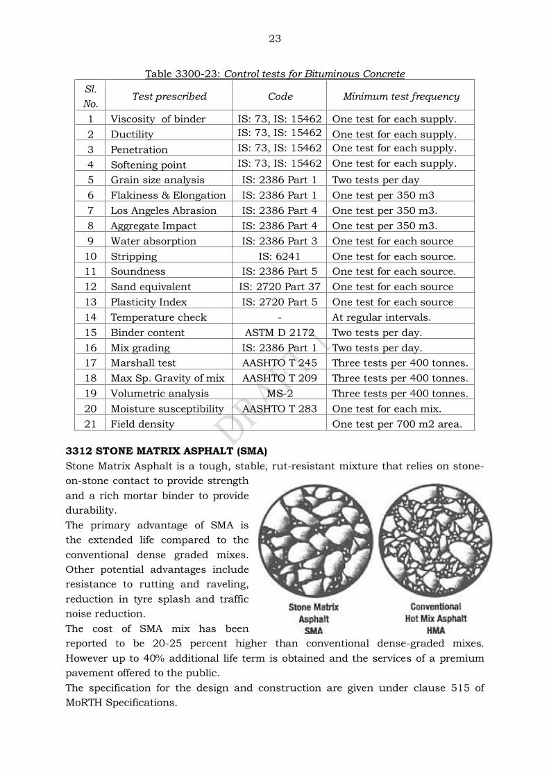
23
Table 3300-23: Control tests for Bituminous Concrete
Sl.
No. Test prescribed Code Minimum test frequency
1 Viscosity of binder IS: 73, IS: 15462 One test for each supply.
2 Ductility IS: 73, IS: 15462 One test for each supply.
3 Penetration IS: 73, IS: 15462 One test for each supply.
4 Softening point IS: 73, IS: 15462 One test for each supply.
5 Grain size analysis IS: 2386 Part 1 Two tests per day
6 Flakiness & Elongation IS: 2386 Part 1 One test per 350 m3
7 Los Angeles Abrasion IS: 2386 Part 4 One test per 350 m3.
8 Aggregate Impact IS: 2386 Part 4 One test per 350 m3.
9 Water absorption IS: 2386 Part 3 One test for each source
10 Stripping IS: 6241 One test for each source.
11 Soundness IS: 2386 Part 5 One test for each source.
12 Sand equivalent IS: 2720 Part 37 One test for each source
13 Plasticity Index IS: 2720 Part 5 One test for each source
14 Temperature check - At regular intervals.
15 Binder content ASTM D 2172 Two tests per day.
16 Mix grading IS: 2386 Part 1 Two tests per day.
17 Marshall test AASHTO T 245 Three tests per 400 tonnes.
18 Max Sp. Gravity of mix AASHTO T 209 Three tests per 400 tonnes.
19 Volumetric analysis MS-2 Three tests per 400 tonnes.
20 Moisture susceptibility AASHTO T 283 One test for each mix.
21 Field density One test per 700 m2 area.
3312 STONE MATRIX ASPHALT (SMA)
Stone Matrix Asphalt is a tough, stable, rut-resistant mixture that relies on stone-
on-stone contact to provide strength
and a rich mortar binder to provide
durability.
The primary advantage of SMA is
the extended life compared to the
conventional dense graded mixes.
Other potential advantages include
resistance to rutting and raveling,
reduction in tyre splash and traffic
noise reduction.
The cost of SMA mix has been
reported to be 20-25 percent higher than conventional dense-graded mixes.
However up to 40% additional life term is obtained and the services of a premium
pavement offered to the public.
The specification for the design and construction are given under clause 515 of
MoRTH Specifications.
24
3312.1 Materials
3312.1.1 Coarse aggregate
The coarse aggregates shall consist of crushed rock retained on 2.36 mm sieve. The
physical requirements shall be as set forth in table 3300-24 (Ref: Table 500-35 of
MoRTH Specifications) given below.
Table 3300-24: Physical requirements of aggregates for Stone Matrix Asphalt
Property Test Method Specification
Cleanliness Grain size analysis IS: 2386 (Part 1)
<2% passing 0.075mm sieve
Particle shape Combined Flakiness
and Elongation Indices IS: 2386 (Part 1)
<30%
Strength
Los Angeles Abrasion Value
IS: 2386 (Part 4)
<25%
Aggregate Impact Value IS: 2386 (Part 4)
<18%
Polishing* Polished Stone Value BS:
812-114 >55%
Durability
Soundness Either Sodium or Magnesium
(5 Cycles)
Sodium Sulphate IS: 2386 (Part 5)
<12%
Magnesium Sulphate IS: 2386 (Part 5)
<18%
Water Absorption Water absorption IS: 2386 (Part 3)
<2%
*Polishing requirement does not apply when the coarse aggregate is used for
Intermediate (binder) course.
3312.1.2 Fine aggregates
a) Non-plastic, fine aggregates passing 2.36 mm sieve and retained on 75
micron sieve, of 100 percent crushed manufactured sand shall be used.
b) The sand equivalent test (IS: 2720-Part 37) value shall not be less than 50.
3312.1.3 Mineral filler
a) Filler shall consist of finely divided matter such as stone dust and/or
hydrated lime.
b) Fly ash shall not be permitted for use as filler for SMA mix.
c) Grading requirements of filler shall be as stipulated in table 3300-25 (Ref:
Table 500-36 of MoRTH Specifications) given below.
Table 3300-25: Physical requirements of filler for SMA
IS Sieve (mm)
Cumulative % passing by weight of total aggregate
0.600 100
0.300 95-100
0.075 85-100
3312.1.4 Stabilizer additive
a) Only palletized cellulose fibre shall be utilised.

25
b) The dosage rate for celluloses fibres is 0.3 percent minimum by weight of the
total mix.
c) The dosage shall be confirmed so that the bitumen drain down does not
exceed 0.3% when the designed mix is tested in accordance with ASTM D
6390.
d) The cellulose fibre shall meet the requirements indicated in table 3300-26
below.
Table 3300-26: Requirements for cellulose fibre for SMA.
Maximum fibre length 8 mm
Ash content Max. of 20% non-volatile
Oil absorption More than 4 times of fibre weight
Moisture content Less than 5% by weight
3312.2 Aggregate grading
The combined grading of the coarse aggregate, fine aggregate and mineral filler shall
be within the limits specified in table 3300-27 (Ref: Table 500-37 of MoRTH
Specifications) below.
Table 3300-27: Composition of Stone Matrix Asphalt
SMA Designation 13 mm SMA 19 mm SMA
Course where used Wearing Course Binder
(Intermediate) Course
Nominal aggregate size
13 mm 19 mm
IS Sieve(mm) Cumulative % by
weight of total aggregate passing
Cumulative % by weight of total aggregate passing
26.5 100
19 100 90-100
13.2 90-100 45-70
9.5 50-75 25-60
4.75 20-28 20-28
2.36 16-24 16-24
1.18 13-21 13-21
0.600 12-18 12-18
0.300 10-20 10-20
0.075 8-12 8-12
3312.3 Mix requirements
a) The SMA mix shall be designed using AASHTO, MP8 standard specification
for Designing stone Matrix Asphalt and AASHTO PP41 - Standard Practice for
Designing SMA.
b) Compaction of the mixture shall be carried and with 50 blows on each side
using Marshall Method given in Asphalt Institute Manual MS-2.
c) The design mix shall meet the requirements given in table 3300-28 (Ref:
Table 500-38 of MoRTH Specifications) given below.
26
Table 3300-28: Stone Matrix Asphalt mix requirements
Mix design parameters Requirement
Air void content, percent 4.0
Bitumen content, percent 5.8
Celluloid fibres 0.3 percent minimum by weight of total mix
Voids in mineral aggregate (VMA), percent 17 min.
Voids in Coarse Aggregates (VCA) mix, percent
Less than VCA (dry rodded)
Asphalt drain down, percent ASTM D 6390 (Annexure C of IRC: SP: 79)
0.3 max.
Tensile Strength Ratio (TSR), per cent AASHTO T 283 (Annexure E of IRC: SP: 79)
85 Min.
3312.4 Mix Design
The five steps required to obtain a satisfactory SMA mixture are given below.
a) Select proper aggregate materials.
b) Determine an aggregate grading which will yield stone- on-stone contact.
c) Ensure that the selected grading meets the minimum VMA requirement and
allows the use of minimum binder contact.
d) Select bitumen content which will provide the desired air voids in the mix.
e) Evaluate the moisture susceptibility and bitumen drain down sensitivity.
3312.5 SMA mix production
a) SMA mix shall be prepared in a hot mix plant of adequate capacity capable of
producing a mix of uniform quality with thoroughly coated aggregate.
b) The mix temperature shall be as recommended by the manufactures. If
viscosity grade bitumen is used, the mix temperature shall be from 150 0C to
165 0C.
c) Mineral filler shall be incorporated properly. Provisions to incorporate the
mineral filler at a uniform rate shall be made.
d) In batch plants, the fibre additive shall be directly weighed in to the hopper
above the pug mill.
e) Adequate mixing time is required to disperse the fibre uniformly though out
the hot aggregate.
f) In drum mix plant, fibre addition is carried out though separate feeding
system. The rate of addition shall be controlled to meet the requirement for a
normal production of the mix. However, no wastage of fibre ion to the bag
house should occur.
3312.6 Construction
a) The existing bituminous surface shall be cleaned of all loose extraneous
matter by means of mechanical broom and high pressure air jet.
b) All pot holes and cracks shall be repaired and sealed.
c) Tack shall be provided on the cleaned surface as per clause 503 of MORTH
specifications.
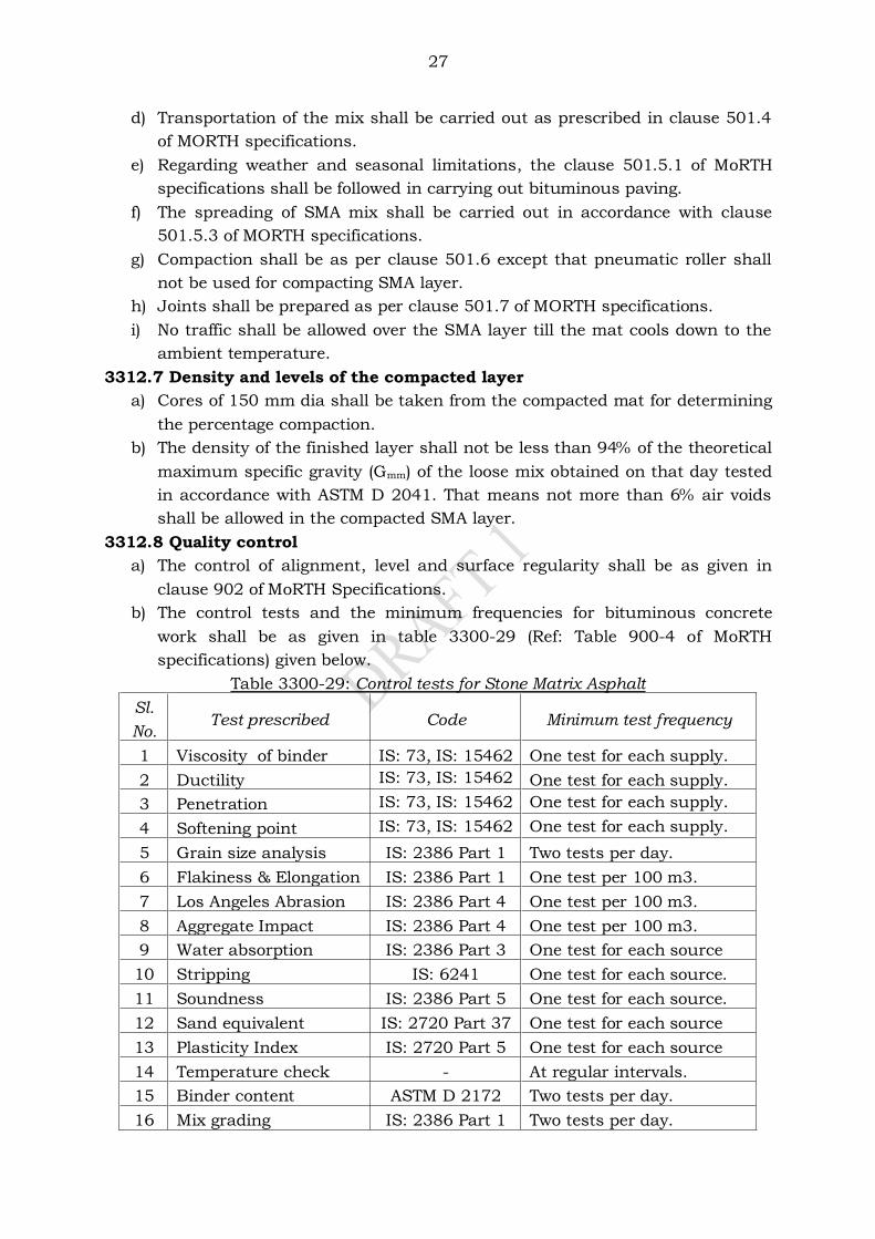
27
d) Transportation of the mix shall be carried out as prescribed in clause 501.4
of MORTH specifications.
e) Regarding weather and seasonal limitations, the clause 501.5.1 of MoRTH
specifications shall be followed in carrying out bituminous paving.
f) The spreading of SMA mix shall be carried out in accordance with clause
501.5.3 of MORTH specifications.
g) Compaction shall be as per clause 501.6 except that pneumatic roller shall
not be used for compacting SMA layer.
h) Joints shall be prepared as per clause 501.7 of MORTH specifications.
i) No traffic shall be allowed over the SMA layer till the mat cools down to the
ambient temperature.
3312.7 Density and levels of the compacted layer
a) Cores of 150 mm dia shall be taken from the compacted mat for determining
the percentage compaction.
b) The density of the finished layer shall not be less than 94% of the theoretical
maximum specific gravity (Gmm) of the loose mix obtained on that day tested
in accordance with ASTM D 2041. That means not more than 6% air voids
shall be allowed in the compacted SMA layer.
3312.8 Quality control
a) The control of alignment, level and surface regularity shall be as given in
clause 902 of MoRTH Specifications.
b) The control tests and the minimum frequencies for bituminous concrete
work shall be as given in table 3300-29 (Ref: Table 900-4 of MoRTH
specifications) given below.
Table 3300-29: Control tests for Stone Matrix Asphalt
Sl.
No. Test prescribed Code Minimum test frequency
1 Viscosity of binder IS: 73, IS: 15462 One test for each supply.
2 Ductility IS: 73, IS: 15462 One test for each supply.
3 Penetration IS: 73, IS: 15462 One test for each supply.
4 Softening point IS: 73, IS: 15462 One test for each supply.
5 Grain size analysis IS: 2386 Part 1 Two tests per day.
6 Flakiness & Elongation IS: 2386 Part 1 One test per 100 m3.
7 Los Angeles Abrasion IS: 2386 Part 4 One test per 100 m3.
8 Aggregate Impact IS: 2386 Part 4 One test per 100 m3.
9 Water absorption IS: 2386 Part 3 One test for each source
10 Stripping IS: 6241 One test for each source.
11 Soundness IS: 2386 Part 5 One test for each source.
12 Sand equivalent IS: 2720 Part 37 One test for each source
13 Plasticity Index IS: 2720 Part 5 One test for each source
14 Temperature check - At regular intervals.
15 Binder content ASTM D 2172 Two tests per day.
16 Mix grading IS: 2386 Part 1 Two tests per day.
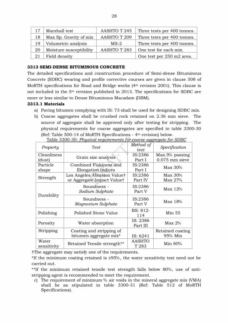
28
17 Marshall test AASHTO T 245 Three tests per 400 tonnes.
18 Max Sp. Gravity of mix AASHTO T 209 Three tests per 400 tonnes.
19 Volumetric analysis MS-2 Three tests per 400 tonnes.
20 Moisture susceptibility AASHTO T 283 One test for each mix.
21 Field density One test per 250 m2 area.
3313 SEMI-DENSE BITUMINOUS CONCRETE
The detailed specifications and construction procedure of Semi-dense Bituminous
Concrete (SDBC) wearing and profile corrective courses are given in clause 508 of
MoRTH specifications for Road and Bridge works (4th revision 2001). This clause is
not included in the 5th revision published in 2013. The specifications for SDBC are
more or less similar to Dense Bituminous Macadam (DBM).
3313.1 Materials
a) Paving bitumen complying with IS: 73 shall be used for designing SDBC mix.
b) Coarse aggregates shall be crushed rock retained on 2.36 mm sieve. The
source of aggregate shall be approved only after testing for stripping. The
physical requirements for coarse aggregates are specified in table 3300-30
(Ref: Table 500-14 of MoRTH Specifications - 4th revision) below. Table 3300-30: Physical requirements for coarse aggregate for SDBC
Property Test Method of
test Specification
Cleanliness (dust)
Grain size analysis IS:2386 Part I
Max.5% passing 0.075 mm sieve
Particle shape
Combined Flakiness and Elongation Indices
IS:2386 Part I
Max 30%
Strength Los Angeles Abrasion Value† or Aggregate Impact Value†
IS:2386 Part IV
Max 30% Max 27%
Durability
Soundness - Sodium Sulphate
IS:2386 Part V
Max 12%
Soundness - Magnesium Sulphate
IS:2386 Part V
Max 18%
Polishing Polished Stone Value BS: 812-
114 Min 55
Porosity Water absorption IS: 2386 Part III
Max 2%
Stripping
Coating and stripping of bitumen aggregate mix*
IS: 6241
Retained coating 95% Min
Water sensitivity
Retained Tensile strength** AASHTO
T 283 Min 80%
†The aggregate may satisfy one of the requirements.
*If the minimum coating retained is ≥95%, the water sensitivity test need not be carried out.
**If the minimum retained tensile test strength falls below 80%, use of anti-
stripping agent is recommended to meet the requirement. c) The requirement of minimum % air voids in the mineral aggregate mix (VMA)
shall be as stipulated in table 3300-31 (Ref: Table 512 of MoRTH Specifications).
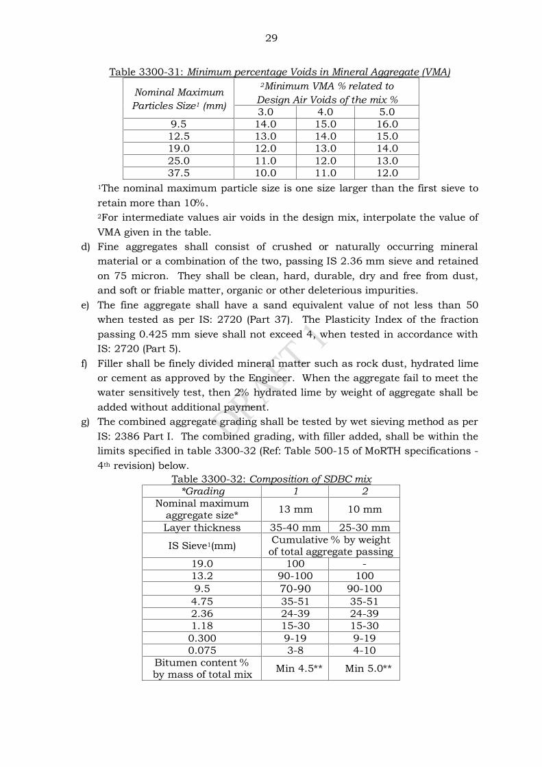
29
Table 3300-31: Minimum percentage Voids in Mineral Aggregate (VMA)
Nominal Maximum
Particles Size1 (mm)
2Minimum VMA % related to
Design Air Voids of the mix % 3.0 4.0 5.0
9.5 14.0 15.0 16.0 12.5 13.0 14.0 15.0 19.0 12.0 13.0 14.0 25.0 11.0 12.0 13.0 37.5 10.0 11.0 12.0
1The nominal maximum particle size is one size larger than the first sieve to
retain more than 10%.
2For intermediate values air voids in the design mix, interpolate the value of
VMA given in the table.
d) Fine aggregates shall consist of crushed or naturally occurring mineral
material or a combination of the two, passing IS 2.36 mm sieve and retained
on 75 micron. They shall be clean, hard, durable, dry and free from dust,
and soft or friable matter, organic or other deleterious impurities.
e) The fine aggregate shall have a sand equivalent value of not less than 50
when tested as per IS: 2720 (Part 37). The Plasticity Index of the fraction
passing 0.425 mm sieve shall not exceed 4, when tested in accordance with
IS: 2720 (Part 5).
f) Filler shall be finely divided mineral matter such as rock dust, hydrated lime
or cement as approved by the Engineer. When the aggregate fail to meet the
water sensitively test, then 2% hydrated lime by weight of aggregate shall be
added without additional payment.
g) The combined aggregate grading shall be tested by wet sieving method as per
IS: 2386 Part I. The combined grading, with filler added, shall be within the
limits specified in table 3300-32 (Ref: Table 500-15 of MoRTH specifications -
4th revision) below.
Table 3300-32: Composition of SDBC mix
*Grading 1 2 Nominal maximum
aggregate size* 13 mm 10 mm
Layer thickness 35-40 mm 25-30 mm
IS Sieve1(mm) Cumulative % by weight of total aggregate passing
19.0 100 - 13.2 90-100 100
9.5 70-90 90-100 4.75 35-51 35-51 2.36 24-39 24-39 1.18 15-30 15-30 0.300 9-19 9-19 0.075 3-8 4-10
Bitumen content % by mass of total mix
Min 4.5** Min 5.0**

30
*The combined aggregate grading shall not vary from the low limit on one sieve to
the high limit on the adjacent side.
**Determined by Marshall Method.
3313.2 Mix requirements
a) The semi-dense bituminous concrete mix shall meet the requirements
stipulated in table 3300-33 (Ref: Table 500-16 of MoRTH Specifications).
Table 3300-33: Mix requirements for Semi-Dense Bituminous Concrete
Mix parameter Requirement
Marshall Stability (kN at 60°C) 2.0 (Min) Marshall Flow (mm) 2-4 Compaction level (Blows) 75 on each face Air voids in the mix (%) 3-5 Voids in the mineral aggregate (VMA) Table 3300-30 Percentage voids filled with bitumen (VFB) 65-75
b) The minimum percentage of air voids in mineral aggregate (VMA) conditions
shall be satisfied for the selected nominal maximum size of aggregates.
c) Binder content shall be optimised to achieve the requirements specified for
the bituminous mix, and the traffic volume of the road.
3313.3 Job mix formula
a) The job mix formula proposed for the work, satisfying the mix requirements
given in table 3300-33 above, shall be given in writing at least 30 days before
the start of the work and got approved by the Engineer.
b) The job mix shall be approved only after independent testing by the Engineer
using the same materials proposes for the work.
c) The job mix formula shall be changed by revised tests, if the source of the
material or the properties of the constituents change.
3313.4 Plant and field trials
a) After the job mix formula is approved, the contractor shall carry out plant
trials to set the plant for producing a uniform mix conforming to the
specification requirements.
b) The variations in quantities of the ingredients from the approved job mix
formula shall not exceed the prescribed limits given in table 3300-34 (Ref:
Table 500-13 of MoRTH Specifications, 4th revision 2001). Table 3300-34: Permissible variations in plant mix from the
Job Mix Formula
Description Permissible Variation
Base/binder course
Wearing course
Aggregate passing 19 mm sieve or larger ±8% ±7% Aggregate passing 13.2 mm, 9.5 mm ±7% ±6% Aggregate passing 4.75 mm ±6% ±5% Aggregate passing 2.36 mm, 1.18 mm, 0.6 mm ±5% ±4% Aggregate passing 0.3 mm, 0.15 mm ±4% ±3% Aggregate passing 0.075 mm ±2% ±1.5% Binder content ±0.3% ±0.3% Mixing Temperature ±10°C ±10°C
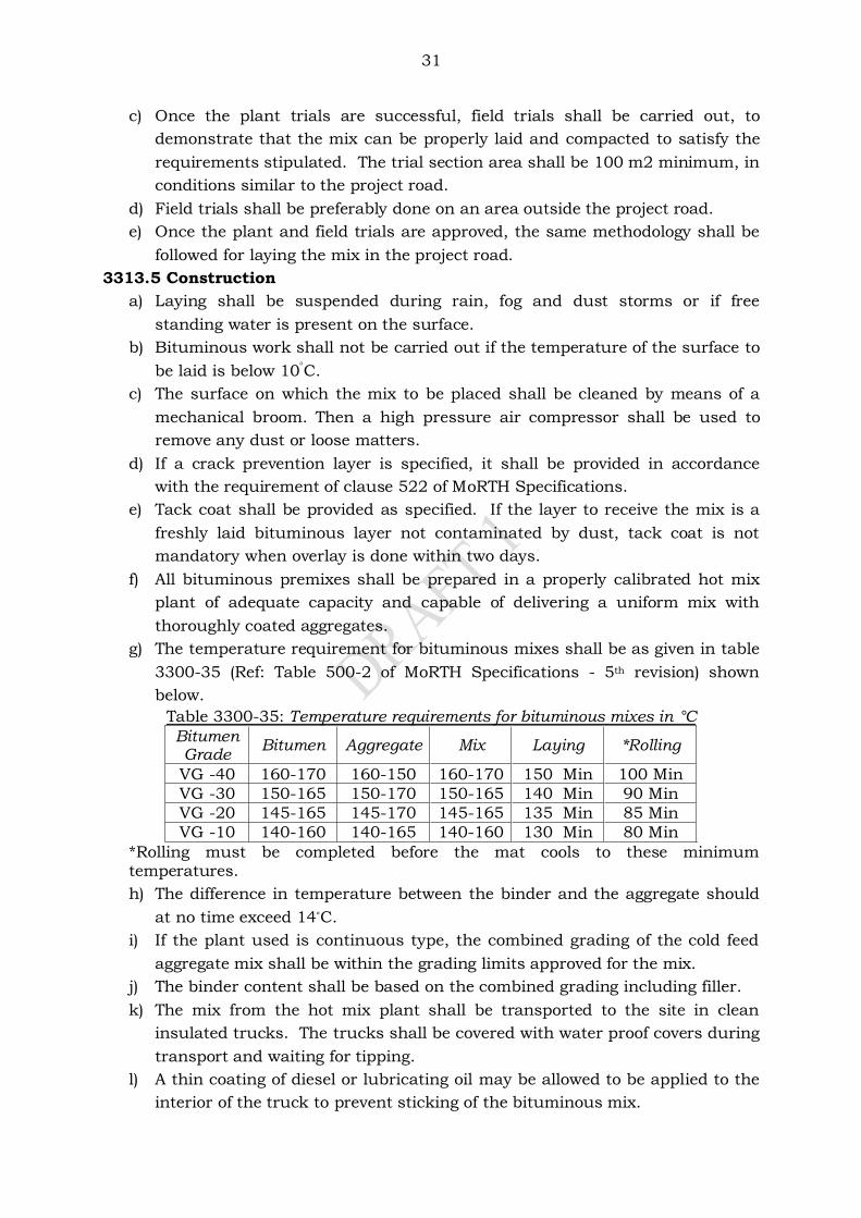
31
c) Once the plant trials are successful, field trials shall be carried out, to
demonstrate that the mix can be properly laid and compacted to satisfy the
requirements stipulated. The trial section area shall be 100 m2 minimum, in
conditions similar to the project road.
d) Field trials shall be preferably done on an area outside the project road.
e) Once the plant and field trials are approved, the same methodology shall be
followed for laying the mix in the project road.
3313.5 Construction
a) Laying shall be suspended during rain, fog and dust storms or if free
standing water is present on the surface.
b) Bituminous work shall not be carried out if the temperature of the surface to
be laid is below 10C.
c) The surface on which the mix to be placed shall be cleaned by means of a
mechanical broom. Then a high pressure air compressor shall be used to
remove any dust or loose matters.
d) If a crack prevention layer is specified, it shall be provided in accordance
with the requirement of clause 522 of MoRTH Specifications.
e) Tack coat shall be provided as specified. If the layer to receive the mix is a
freshly laid bituminous layer not contaminated by dust, tack coat is not
mandatory when overlay is done within two days.
f) All bituminous premixes shall be prepared in a properly calibrated hot mix
plant of adequate capacity and capable of delivering a uniform mix with
thoroughly coated aggregates.
g) The temperature requirement for bituminous mixes shall be as given in table
3300-35 (Ref: Table 500-2 of MoRTH Specifications - 5th revision) shown
below.
Table 3300-35: Temperature requirements for bituminous mixes in °C
Bitumen Grade
Bitumen Aggregate Mix Laying *Rolling
VG -40 160-170 160-150 160-170 150 Min 100 Min VG -30 150-165 150-170 150-165 140 Min 90 Min VG -20 145-165 145-170 145-165 135 Min 85 Min VG -10 140-160 140-165 140-160 130 Min 80 Min
*Rolling must be completed before the mat cools to these minimum temperatures.
h) The difference in temperature between the binder and the aggregate should
at no time exceed 14°C.
i) If the plant used is continuous type, the combined grading of the cold feed
aggregate mix shall be within the grading limits approved for the mix.
j) The binder content shall be based on the combined grading including filler.
k) The mix from the hot mix plant shall be transported to the site in clean
insulated trucks. The trucks shall be covered with water proof covers during
transport and waiting for tipping.
l) A thin coating of diesel or lubricating oil may be allowed to be applied to the
interior of the truck to prevent sticking of the bituminous mix.
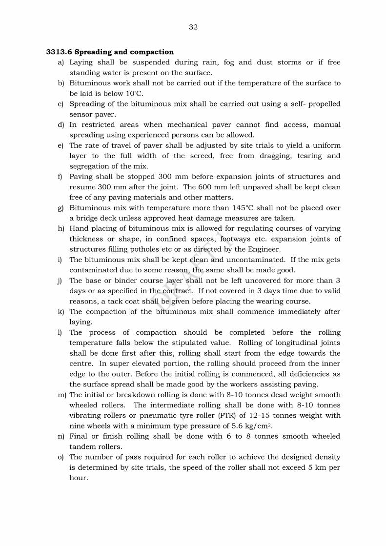
32
3313.6 Spreading and compaction
a) Laying shall be suspended during rain, fog and dust storms or if free
standing water is present on the surface.
b) Bituminous work shall not be carried out if the temperature of the surface to
be laid is below 10°C.
c) Spreading of the bituminous mix shall be carried out using a self- propelled
sensor paver.
d) In restricted areas when mechanical paver cannot find access, manual
spreading using experienced persons can be allowed.
e) The rate of travel of paver shall be adjusted by site trials to yield a uniform
layer to the full width of the screed, free from dragging, tearing and
segregation of the mix.
f) Paving shall be stopped 300 mm before expansion joints of structures and
resume 300 mm after the joint. The 600 mm left unpaved shall be kept clean
free of any paving materials and other matters.
g) Bituminous mix with temperature more than 145°C shall not be placed over
a bridge deck unless approved heat damage measures are taken.
h) Hand placing of bituminous mix is allowed for regulating courses of varying
thickness or shape, in confined spaces, footways etc. expansion joints of
structures filling potholes etc or as directed by the Engineer.
i) The bituminous mix shall be kept clean and uncontaminated. If the mix gets
contaminated due to some reason, the same shall be made good.
j) The base or binder course layer shall not be left uncovered for more than 3
days or as specified in the contract. If not covered in 3 days time due to valid
reasons, a tack coat shall be given before placing the wearing course.
k) The compaction of the bituminous mix shall commence immediately after
laying.
l) The process of compaction should be completed before the rolling
temperature falls below the stipulated value. Rolling of longitudinal joints
shall be done first after this, rolling shall start from the edge towards the
centre. In super elevated portion, the rolling should proceed from the inner
edge to the outer. Before the initial rolling is commenced, all deficiencies as
the surface spread shall be made good by the workers assisting paving.
m) The initial or breakdown rolling is done with 8-10 tonnes dead weight smooth
wheeled rollers. The intermediate rolling shall be done with 8-10 tonnes
vibrating rollers or pneumatic tyre roller (PTR) of 12-15 tonnes weight with
nine wheels with a minimum type pressure of 5.6 kg/cm2.
n) Final or finish rolling shall be done with 6 to 8 tonnes smooth wheeled
tandem rollers.
o) The number of pass required for each roller to achieve the designed density
is determined by site trials, the speed of the roller shall not exceed 5 km per
hour.
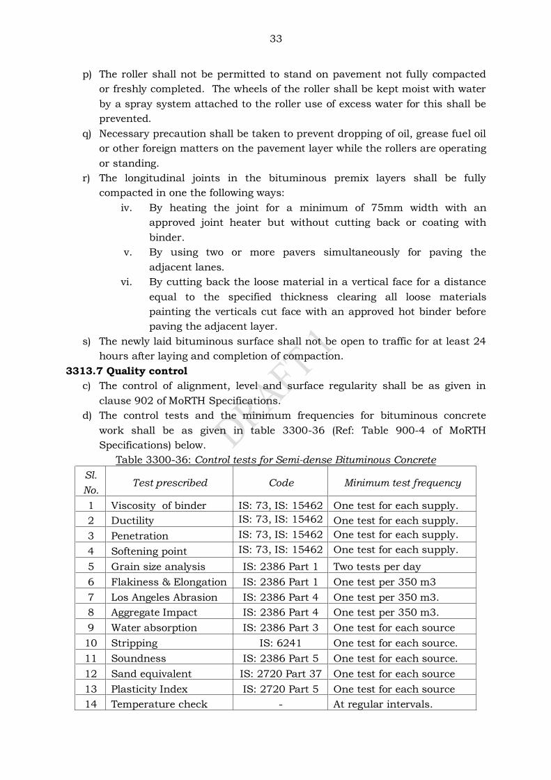
33
p) The roller shall not be permitted to stand on pavement not fully compacted
or freshly completed. The wheels of the roller shall be kept moist with water
by a spray system attached to the roller use of excess water for this shall be
prevented.
q) Necessary precaution shall be taken to prevent dropping of oil, grease fuel oil
or other foreign matters on the pavement layer while the rollers are operating
or standing.
r) The longitudinal joints in the bituminous premix layers shall be fully
compacted in one the following ways:
iv. By heating the joint for a minimum of 75mm width with an
approved joint heater but without cutting back or coating with
binder.
v. By using two or more pavers simultaneously for paving the
adjacent lanes.
vi. By cutting back the loose material in a vertical face for a distance
equal to the specified thickness clearing all loose materials
painting the verticals cut face with an approved hot binder before
paving the adjacent layer.
s) The newly laid bituminous surface shall not be open to traffic for at least 24
hours after laying and completion of compaction.
3313.7 Quality control
c) The control of alignment, level and surface regularity shall be as given in
clause 902 of MoRTH Specifications.
d) The control tests and the minimum frequencies for bituminous concrete
work shall be as given in table 3300-36 (Ref: Table 900-4 of MoRTH
Specifications) below.
Table 3300-36: Control tests for Semi-dense Bituminous Concrete
Sl.
No. Test prescribed Code Minimum test frequency
1 Viscosity of binder IS: 73, IS: 15462 One test for each supply.
2 Ductility IS: 73, IS: 15462 One test for each supply.
3 Penetration IS: 73, IS: 15462 One test for each supply.
4 Softening point IS: 73, IS: 15462 One test for each supply.
5 Grain size analysis IS: 2386 Part 1 Two tests per day
6 Flakiness & Elongation IS: 2386 Part 1 One test per 350 m3
7 Los Angeles Abrasion IS: 2386 Part 4 One test per 350 m3.
8 Aggregate Impact IS: 2386 Part 4 One test per 350 m3.
9 Water absorption IS: 2386 Part 3 One test for each source
10 Stripping IS: 6241 One test for each source.
11 Soundness IS: 2386 Part 5 One test for each source.
12 Sand equivalent IS: 2720 Part 37 One test for each source
13 Plasticity Index IS: 2720 Part 5 One test for each source
14 Temperature check - At regular intervals.
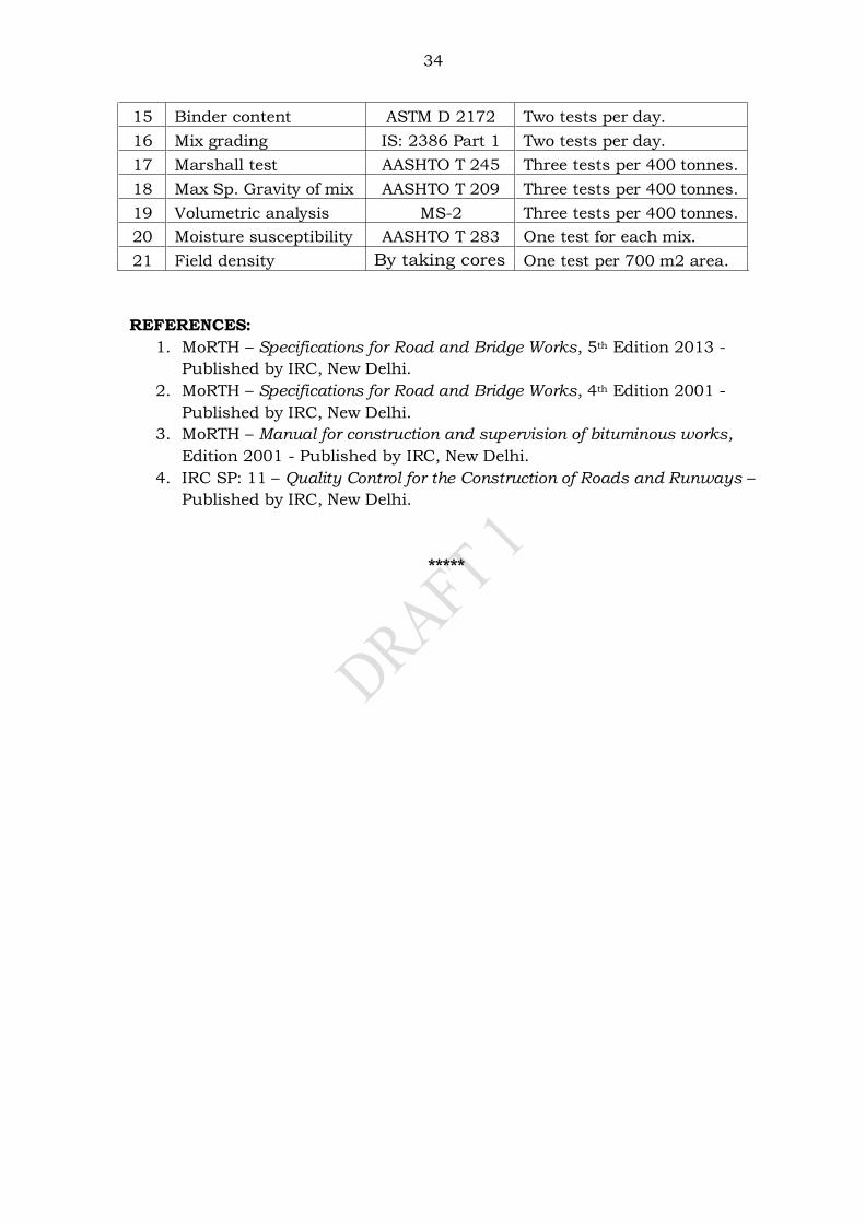
34
15 Binder content ASTM D 2172 Two tests per day.
16 Mix grading IS: 2386 Part 1 Two tests per day.
17 Marshall test AASHTO T 245 Three tests per 400 tonnes.
18 Max Sp. Gravity of mix AASHTO T 209 Three tests per 400 tonnes.
19 Volumetric analysis MS-2 Three tests per 400 tonnes.
20 Moisture susceptibility AASHTO T 283 One test for each mix.
21 Field density By taking cores One test per 700 m2 area.
REFERENCES:
1. MoRTH – Specifications for Road and Bridge Works, 5th Edition 2013 -
Published by IRC, New Delhi.
2. MoRTH – Specifications for Road and Bridge Works, 4th Edition 2001 -
Published by IRC, New Delhi.
3. MoRTH – Manual for construction and supervision of bituminous works,
Edition 2001 - Published by IRC, New Delhi.
4. IRC SP: 11 – Quality Control for the Construction of Roads and Runways –
Published by IRC, New Delhi.
*****
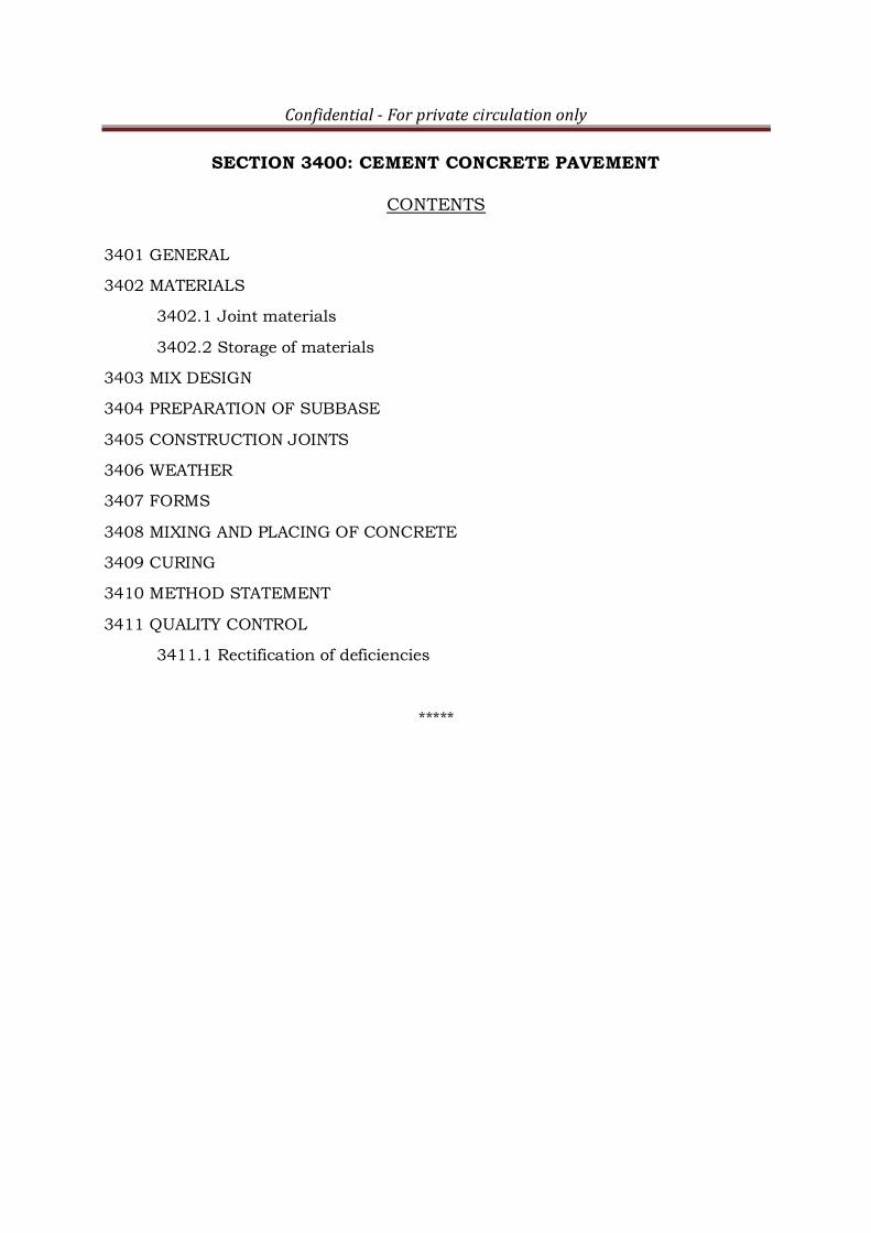
Confidential - For private circulation only
SECTION 3400: CEMENT CONCRETE PAVEMENT
CONTENTS
3401 GENERAL
3402 MATERIALS
3402.1 Joint materials
3402.2 Storage of materials
3403 MIX DESIGN
3404 PREPARATION OF SUBBASE
3405 CONSTRUCTION JOINTS
3406 WEATHER
3407 FORMS
3408 MIXING AND PLACING OF CONCRETE
3409 CURING
3410 METHOD STATEMENT
3411 QUALITY CONTROL
3411.1 Rectification of deficiencies
*****
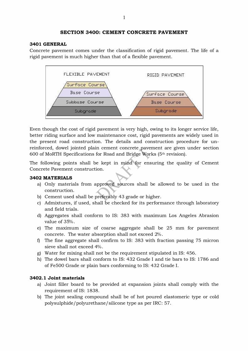
1
SECTION 3400: CEMENT CONCRETE PAVEMENT
3401 GENERAL
Concrete pavement comes under the classification of rigid pavement. The life of a
rigid pavement is much higher than that of a flexible pavement.
Even though the cost of rigid pavement is very high, owing to its longer service life,
better riding surface and low maintenance cost, rigid pavements are widely used in
the present road construction. The details and construction procedure for un-
reinforced, dowel jointed plain cement concrete pavement are given under section
600 of MoRTH Specifications for Road and Bridge Works (5th revision).
The following points shall be kept in mind for ensuring the quality of Cement
Concrete Pavement construction.
3402 MATERIALS
a) Only materials from approved sources shall be allowed to be used in the
construction.
b) Cement used shall be preferably 43 grade or higher.
c) Admixtures, if used, shall be checked for its performance through laboratory
and field trials.
d) Aggregates shall conform to IS: 383 with maximum Los Angeles Abrasion
value of 35%.
e) The maximum size of coarse aggregate shall be 25 mm for pavement
concrete. The water absorption shall not exceed 2%.
f) The fine aggregate shall confirm to IS: 383 with fraction passing 75 micron
sieve shall not exceed 4%.
g) Water for mixing shall not be the requirement stipulated in IS: 456.
h) The dowel bars shall conform to IS: 432 Grade I and tie bars to IS: 1786 and
of Fe500 Grade or plain bars conforming to IS: 432 Grade I.
3402.1 Joint materials
a) Joint filler board to be provided at expansion joints shall comply with the
requirement of IS: 1838.
b) The joint sealing compound shall be of hot poured elastomeric type or cold
polysulphide/polyurethane/silicone type as per IRC: 57.
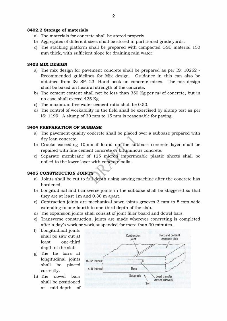
2
3402.2 Storage of materials
a) The materials for concrete shall be stored properly.
b) Aggregates of different sizes shall be stored in partitioned grade yards.
c) The stacking platform shall be prepared with compacted GSB material 150
mm thick, with sufficient slope for draining rain water.
3403 MIX DESIGN
a) The mix design for pavement concrete shall be prepared as per IS: 10262 -
Recommended guidelines for Mix design. Guidance in this can also be
obtained from IS: SP: 23- Hand book on concrete mixes. The mix design
shall be based on flexural strength of the concrete.
b) The cement content shall not be less than 350 Kg per m3 of concrete, but in
no case shall exceed 425 Kg.
c) The maximum free water cement ratio shall be 0.50.
d) The control of workability in the field shall be exercised by slump test as per
IS: 1199. A slump of 30 mm to 15 mm is reasonable for paving.
3404 PREPARATION OF SUBBASE
a) The pavement quality concrete shall be placed over a subbase prepared with
dry lean concrete.
b) Cracks exceeding 10mm if found on the subbase concrete layer shall be
repaired with fine cement concrete or bituminous concrete.
c) Separate membrane of 125 micron impermeable plastic sheets shall be
nailed to the lower layer with concrete nails.
3405 CONSTRUCTION JOINTS
a) Joints shall be cut to full depth using sawing machine after the concrete has
hardened.
b) Longitudinal and transverse joints in the subbase shall be staggered so that
they are at least 1m and 0.30 m apart.
c) Contraction joints are mechanical sawn joints grooves 3 mm to 5 mm wide
extending to one-fourth to one-third depth of the slab.
d) The expansion joints shall consist of joint filler board and dowel bars.
e) Transverse construction, joints are made wherever concreting is completed
after a day’s work or work suspended for more than 30 minutes.
f) Longitudinal joints
shall be saw cut at
least one-third
depth of the slab.
g) The tie bars at
longitudinal joints
shall be placed
correctly.
h) The dowel bars
shall be positioned
at mid-depth of
3
the slab, aligned parallel to the surface of the slab and to the centre line of
the carriage way, unless otherwise specified in the drawing.
i) The dowel bars supported on cradles in assemblies shall be checked for
deflection and shall be within limits given under clause 602.6.5.2 of MoRTH
Specifications mentioned below:
i. All bars in joint shall be within ±2 mm per 300 mm length.
ii. Two-third of the total bars shall be within ±3 mm per 500 mm length.
iii. No bar shall differ in alignment from an adjoining bar by more than
300 mm length of bar in either the horizontal or vertical plane.
iv. Cradles supporting the dowel bar shall not extend across the line of
joint.
j) For bars inserted using a Dowel Bar Inserter, the tolerance for alignment
may be twice as indicated above.
k) The dowel bars shall be covered by a thin plastic sheath to the specified
length.
l) Transverse joints at curves shall be radial in the direction of the radius.
3406 WEATHER
a) When concreting is done in rainy season, sufficient supply of tarpaulin or
water proof cloth shall be kept along the line of work.
b) Any concrete damaged by rain shall be renewed and replaced.
c) No concreting shall be done if the concrete temperature is above 30C.
3407 FORMS
a) All side forms shall be of mild steel of depth equal to the thickness of the
pavement layer. The form shall not be removed for at least 12 hours after
the paving is completed.
b) Sufficient length of forms shall be set in advance to ensure uninterrupted
paving for 2 days.
c) When slip form paving is used, a guide wire shall be provided along both
sides of the slab.
d) The stakes supporting the guidewires, through connectors shall be spaced 5
to 6 m apart. On curves, stakes shall be spaced at not more than 3 m,
centre-to centre.
e) The line and levels of the stakes and connectors shall be made available on
the previous day of paving for checking and effecting any corrections
required.
3408 MIXING AND PLACING OF CONCRETE
a) The concrete mixing shall be carried out in a central batching plant provided
with automatic controls.
b) The speed of mixing and placing of concrete shall be controlled to ensure
proper finishing, protection and curing of the concrete placed.
c) The surface of the slab shall be brush-textured in a direction at right angles
to the longitudinal axis of the carriage way.

4
3409 CURING
a) Immediately after texturing, the surface and sides of the slab shall be cured
by applying approved curing compound by mechanical sprayers.
b) After 3 hours, the surface shall be covered with moist hessian and kept
damp for 14 days.
3410 METHOD STATEMENT
a) A method statement for carrying out the concrete paving shall be prepared
and got approved before commencement of the work.
b) A trial length of at least 60 m shall be constructed one month in advance of
the proposed start of concrete paving work.
c) The trial section shall be prepared away from the carriage way but with at
least a subbase layer below it.
3411 QUALITY CONTROL
a) The surface levels and regularities shall be checked for compliance with
respect to Clause 902.3 and 902.4 of MoRTH Specifications (5th revision).
b) Density of the paved layer shall be assessed from at least 3 cores from each
part of the trial section.
c) No vehicular traffic is allowed to run on the finished surface of a concrete
pavement within a period of 28 days of its construction and until the joints
are permanently sealed.
3411.1 Rectification of deficiencies
a) Appropriate deduction in the rate shall be effected for deficiencies in
thickness of the layer.
b) If deficiency of average thickness is more than 25 mm, the areas deficient by
more than 25 mm is identified by coring, removed and reconstructed by the
contractor at his cost.
c) Deficient slab identified shall be removed and reconstructed to the full depth.
*****
Confidential - For private circulation only
SECTION 3500: MAINTENANCE OF ROAD
CONTENTS
3501. GENERAL
3502. DETERIORATION OF BITUMINOUS SURFACES
3503. CLASSIFICATION OF MAINTENANCE OF BITUMINOUS PAVEMENTS
3504. EVALUATING THE NEED FOR MAINTENANCE
3505. SURFACE DEFECTS AND THEIR RECTIFICATION
3505.1 Fatty surface
3505.1.1 Treatment of fatty surface
3505.2 Smooth surface
3505 2.1 Treatment of smooth surface
3505.3 Streaking
3505.3.1 Treatment of streakiness
3505.4 Hungry or Lean surface
3505.4.1 Treatment of Hungry surfaces.
3506 CRACKS ON THE PAVEMENT SURFACE
3506.1 Hair-line Cracks
3506.1.1 Prevention of cracks
3506.2 Alligator Cracks
3506.3 Longitudinal cracks
3506.4 Edge cracks
3506.5 Block cracking
3506.6 Reflection cracks
3507 TREATMENT OF CRACKS
3507.1 Crack sealing
3507.2 Crack filling
3507.3 Crack prevention course
3508 LAYER DEFORMATION AND THEIR RECTIFICATION
3508.1 General
3508.2 Slippage
3508.2.1 Treatment of slippage
3508.3 Rutting
3508.3.1 Treatment of rutting
3508.4 Corrugations
3508.4.1 Treatment of corrugated layer
3508.5 Shoving
3508.6 Shallow depressions
3508.7 Potholes
3508.9 Settlement and upheaval

3508.9.1 Treating of the settlement and upheavals
3508.10 Stripping
3508.10.1 Treatment for stripping
3508.11 Loss of aggregates
3508.11.1 Treatment for loss of aggregates
3508.12 Raveling
3508.12.1 Treatment for raveling
3509 RESTORATION OF RAIN CUT
3510 MAINTENANCE OF EARTHEN SHOULDER
3511 JOINT REPAIRS OF CONCRETE ROAD
*****
1
SECTION 3500: MAINTENANCE OF ROAD
3501. GENERAL
Life of a pavement system can be improved by timely and proper maintenance.
Reconstruction of the pavement becomes inevitable, if timely maintenance is not
carried out. This section covers the different types of surface and layer failures
noticed on bituminous surfaces and the commonly followed remedial measures. The
section also covers restoration of the eroded embankment and shoulders, repairing
of concrete pavement etc.
3502. DETERIORATION OF BITUMINOUS SURFACES
A bituminous surface deteriorates with passage of time due to the following
reasons:
a) Action of wheel load from vehicles on the pavement layer.
b) Ingress of water, oxidation of the binder, loss of volatiles etc.
c) Inadequate design and improper specifications and lack of quality in
construction.
d) Insufficient capacity of lower pavement layers.
e) Poor drainage conditions.
f) Lack of maintenance of shoulders.
3503. CLASSIFICATION OF MAINTENANCE OF BITUMINOUS PAVEMENTS
a) Routine maintenance: This includes activities such as pothole patching, crack
sealing, shoulder repairing etc.
b) Periodic maintenance: This work is carried out in every few years of time to
prevent deterioration. It covers works such as applying a seal or thin
resurfacing course.
c) Rehabilitation and strengthening: These are mostly major works to restore or
upgrade the pavement. The work covers thick overlays like Bituminous
Macadam (BM) or/and Bituminous Concrete (BC).
3504. EVALUATING THE NEED FOR MAINTENANCE
The need for maintenance is assessed on the basis of condition surveys carried out
in the following ways.
a) Visual rating: The pavement surface is inspected and the severity of damages
is visually assessed. The types of distress checked are rutting, raveling,
pothole, amount of patching done already, cracks, edge failures etc.
b) Roughness measurements: The riding quality of pavement can be measured
by a Bump Integrator. The roughness value in mm/km for different types of
pavement surface recommended by MoRTH is indicated in table 3500-1.
c) Deflection measurements: Benkelman Beam Deflection (BBD) measurements
are used in India for designing thickness of overlay, although the method is
not precise.
Falling Weight Deflectometer (FWD) is used to measure residual life of
pavement. This is a quick and accurate test but requires some capital
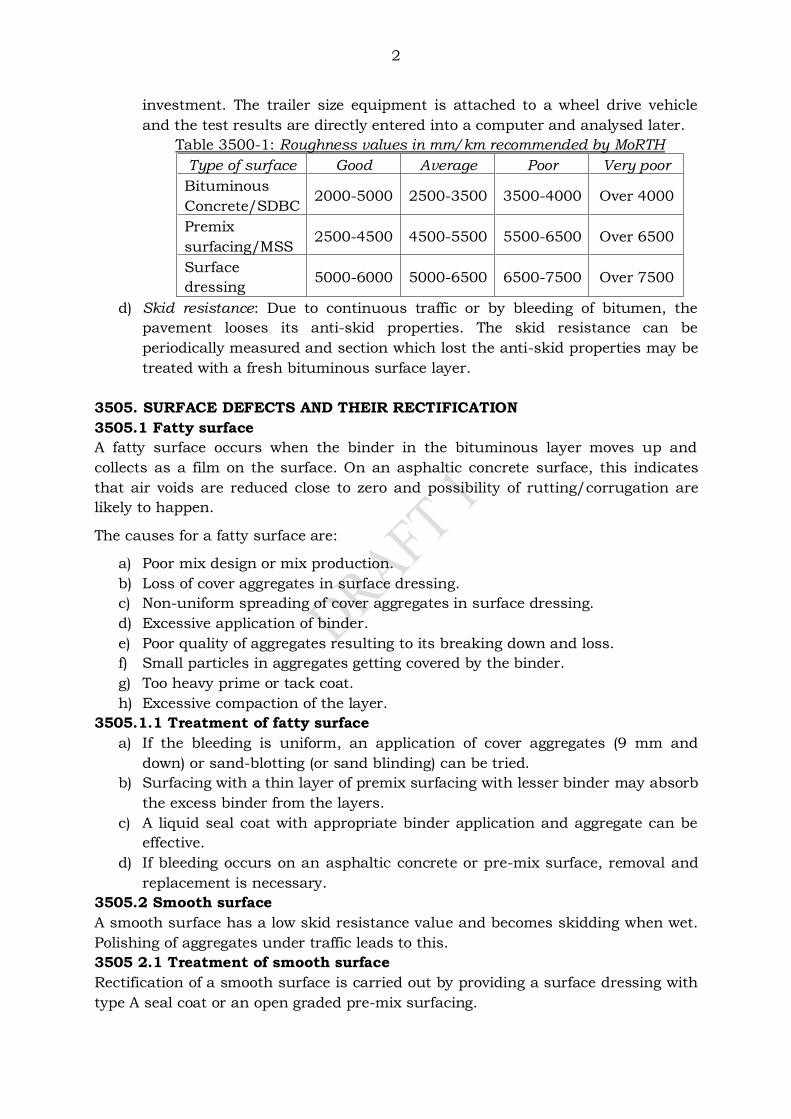
2
investment. The trailer size equipment is attached to a wheel drive vehicle
and the test results are directly entered into a computer and analysed later.
Table 3500-1: Roughness values in mm/km recommended by MoRTH
Type of surface Good Average Poor Very poor
Bituminous
Concrete/SDBC 2000-5000 2500-3500 3500-4000 Over 4000
Premix
surfacing/MSS 2500-4500 4500-5500 5500-6500 Over 6500
Surface
dressing 5000-6000 5000-6500 6500-7500 Over 7500
d) Skid resistance: Due to continuous traffic or by bleeding of bitumen, the
pavement looses its anti-skid properties. The skid resistance can be
periodically measured and section which lost the anti-skid properties may be
treated with a fresh bituminous surface layer.
3505. SURFACE DEFECTS AND THEIR RECTIFICATION
3505.1 Fatty surface
A fatty surface occurs when the binder in the bituminous layer moves up and
collects as a film on the surface. On an asphaltic concrete surface, this indicates
that air voids are reduced close to zero and possibility of rutting/corrugation are
likely to happen.
The causes for a fatty surface are:
a) Poor mix design or mix production.
b) Loss of cover aggregates in surface dressing.
c) Non-uniform spreading of cover aggregates in surface dressing.
d) Excessive application of binder.
e) Poor quality of aggregates resulting to its breaking down and loss.
f) Small particles in aggregates getting covered by the binder.
g) Too heavy prime or tack coat.
h) Excessive compaction of the layer.
3505.1.1 Treatment of fatty surface
a) If the bleeding is uniform, an application of cover aggregates (9 mm and
down) or sand-blotting (or sand blinding) can be tried.
b) Surfacing with a thin layer of premix surfacing with lesser binder may absorb
the excess binder from the layers.
c) A liquid seal coat with appropriate binder application and aggregate can be
effective.
d) If bleeding occurs on an asphaltic concrete or pre-mix surface, removal and
replacement is necessary.
3505.2 Smooth surface
A smooth surface has a low skid resistance value and becomes skidding when wet.
Polishing of aggregates under traffic leads to this.
3505 2.1 Treatment of smooth surface
Rectification of a smooth surface is carried out by providing a surface dressing with
type A seal coat or an open graded pre-mix surfacing.
3
3505.3 Streaking
This is appearance of alternate lean and fatty lines of bitumen usually in a
longitudinal form. Streaking in surface dressing is caused by non-uniform
application of bitumen from distributors, temperature of binder low at the time of
spraying etc.
3505.3.1 Treatment of streakiness
This defect cannot be rectified by any treatments. Hence proper care shall be
enforced while using mechanical sprayers or distributors for applying tack or prime
coat.
3505.4 Hungry or Lean surface
A hungry surface is created when the fine aggregate and bitumen between the
course aggregates is lost. Hungry surface is prone to “raveling” where the
aggregates are picked by traffic, which leads to formation of pot holes.
The hungry surface may be caused by the following reasons:
a) Use of insufficient binder in the mix.
b) Aggregates with higher value of absorption used in the layer.
c) Oxidisation bitumen on an old surface which takes off the aggregate by the
action of traffic.
d) Error in mixing procedure
3505.4.1 Treatment of Hungry surfaces.
Surface dressing/pre-mix surfacing is the remedial measure for a hungry surface.
A slurry seal of 2 mm to 5 mm thickness is an alternative.
3506 CRACKS ON THE PAVEMENT SURFACE
3506.1 Hair-line Cracks
Hair-Line cracks appear as short and fine cracks at close intervals on the surface.
Cracks can be observed by inspection on foot. Hair-line cracks are caused by:
a) Insufficient bitumen content.
b) Excessive fines on the surfaces.
c) Compaction when the mix is too hot
d) Over compaction when the supporting layer is unstable.
3506.1.1 Prevention of cracks
If the steel drums or wheels of the rollers are cold, hair-line cracking can be noticed
on a newly laid surface during initial rolling. These cracks normally closed when
pneumatic tyred roller (PTR) is used for intermediate rolling. If cracks are visible
after paving is completed, the design of the mix and paving techniques needs to be
reviewed.
3506.2 Alligator Cracks
These appear as interconnected cracks forming a series of regular small blocks up
to 100 mm size. Alligator cracks are caused due to following reasons:
a) Excessive deflection of the pavement layer due to week sub grade or sub
base layer below.
b) Excessive and overloading of the layer or inadequate pavement thickness.
c) Ageing of the binder may lead to fine cracks of the alligator pattern.
Initial over heating of the binder may also cause alligator cracks. Such
cracks are also called as ‘Crazing’.
4
Alligator cracks can be taken as a sign of base failure. The remedial measures are
based on the level of failure or distress. Detailed investigations are necessary.
3506.3 Longitudinal cracks
These cracks appear mostly in a straight line either at the joint between pavement
and shoulder or between adjoining lanes. Longitudinal cracks are caused if:
a) The joint between the adjoining lanes is weak.
b) The joints in the layer beneath are not staggered.
c) The joint between shoulder and pavement allow water to penetrate.
d) Poor drainage conditions exist below shoulder.
e) There is settlement of shoulder due to passing of truck over the joint.
3506.4 Edge cracks
These are formed parallel to the outer edge of the pavement with in a distance of 0.3
m to 0.5 m from the edge. Some transverse cracks also appear towards the
shoulder. If not sealed early, excavation and complete replacement of the area will
be required.
Edge cracks are caused due to the following reasons:
a) Lack of lateral support from the shoulder.
b) Settlement or yielding of the underlying material.
c) Inadequate surface drainage.
d) Shrinkage due to drying of one of the underlying earth. The roots of trees
close to the pavement edge contribute to this.
e) Presence of highly expansive soil below pavement layer.
f) Inadequate pavement width forcing vehicle to use edge of pavement often.
g) When extra widening is not provided on curves.
3506.5 Block cracking
The cracks appear in the form of blocks. Block cracks are resulting from widely
spaced longitudinal cracks when associated with transverse cracking. Brittleness of
binder is a major factor contributing block cracking.
3506.6 Reflection cracks
Reflection crakes are resulting from cracks and joints of the pavement layer
underneath. This is mostly seen in overlays placed over cement concrete
pavements or cement-soil bases. If the overlay is placed without treatment of the
cracks in the existing pavement, reflection cracks can occur. When a pavement is
widened and the entire pavement is resurfaced, reflection cracks occur at the joint
of the old pavement and the newly constructed strip. These cracks can allow water
to enter the underlying pavement and the sub grade, causing further deterioration.
Reflection cracks can result from the vertical or horizontal movements at joints and
cracks in the pavement layer underneath.
3507 TREATMENT OF CRACKS
3507.1 Crack sealing
Areas having cracks with less than 3 mm width treatment by fog spraying
conforming to clause of MoRTH Specification shall be carried out. If wider cracks
are present, they shall be sealed and a surface dressing/pre-mix surfacing shall be
provided.
5
3507.2 Crack filling
a) Crack filling is normally carried out with a slow setting bitumen emulsion.
b) For cracks exceeding 8 mm width, application of crusher dust passing 4.75
mm sieve and not more than 10% passing 0.075mm sieve shall be carried
out before emulsion is applied.
c) The dust is filled to a level 5 mm below the surface.
d) After cleaning the surface emulsion is carefully filled into the gap.
e) Any spillage of bitumen shall be properly removed by blotting.
f) For wider cracks say 12 mm or more, sand-bitumen mix prepared by hand
mixing is good crack filler.
3507.3 Crack prevention course
Stress Absorbing Membranes (SAM) or Stress Absorbing Membranes Interlaying
(SAMI) are used for prevention of cracks. The details are given clause 517 of
MoRTH Specifications.
3508 LAYER DEFORMATION AND THEIR RECTIFICATION
3508.1 General
Any change in the shape of the pavement from its original shape is a deformation.
If may be associated with slippage, rutting etc.
3508.2 Slippage
The relative movement of the surface layer with respect to the layer below is called
slippage. This normally occurs when there is a low strength surface layer or poor
bonding exists between the surface and the next layer of the pavement structure.
Slippage is characterized by crescent shape cracks, mostly formed by breaking or
turning vehicles. Slippage is caused by:
a) Unusual thrust by wheels on the surface in a particular direction.
b) Inadequacy of tack or prime coat.
c) Poor bonding between layers caused by dust moisture etc.
d) Failure of bond between the layers caused due to excessive deflection
under wheel load.
3508.2.1 Treatment of slippage
The surface layer showing poor bonding is removed and patching to be done after
applying necessary tack coat.
3508.3 Rutting
Longitudinal groove or depression along the wheel track is called rutting. Rutting is
caused by:
a) Heavy, channeled traffic.
b) Inadequate compaction of the pavement layer.
c) Improper mix design - mix of low stability and high flow is used.
d) Weak pavement- not designed to the actual traffic conditions.
e) High contact stress caused by heavy bullock-cart traffic.
f) Mud pumping from subgrade into the sub base layer.
g) Aggregate of surface dressing being pressed into the lower layer.
3508.3.1 Treatment of rutting
a) The rectification consists of filling up with bituminous premix - open or
dense graded - and compacting to the desired level.
6
b) The limits of the rutting are measured using a string line and marked on
the surface. After applying a tack coat, the premix is spread and
compacted.
If shear failure or movement of sub grade is noticed, reconstruction is required.
3508.4 Corrugations
Formation of fairly regular undulation or ripples across a bituminous surface is
called corrugation. They are normally shallow, about 25mm depth, located at a
spacing of around 3 m. Large depressions caused by the weak pavement layer or
subgrade do not come under this category.
Corrugations are cause due to:
a) Lack of stability of the mix due to excess or soft binder, high proportion of
fines, smooth textured aggregates in the mix etc.
b) Oscillations by the vehicle spring causing alternate valley and ridges.
c) Faulty laying of surface course.
3508.4.1 Treatment of corrugated layer
a) If the surface is thin, it is scarified and recomputed and a new surfacing
layer is then placed.
b) Cutting of the high spots with or without heating and adding of leveling
course material also can be adopted.
c) Sand-bitumen mix spread, using a drop spreader with its blade adjusted
to clear off the high spots, can be effective to make up the corruptions.
The area is then rolled thoroughly.
3508.5 Shoving
Shoving is caused by the plastic movement within the layer resulting in localised
bulging of the pavement surface. Shoving is generally exhibited at the
intersections, hills or grades and on sharp curves. Shoving can be caused due to:
a) Lack of stability of the mix due to excess or soft binder, high proportion of
fines, smooth textured aggregates in the mix etc.
b) Lack of bonding between the surface and the layer below.
c) Heavy traffic movement of a start and stop type or involving negotiation of
curves and gradients.
d) Use of non-volatile oil on roller wheels.
3508.6 Shallow depressions
Localised shallow depression below 25 mm are filled up with premix material and
compacted to the desired profile. The following steps shall be followed in filling
shallow depression:
a) Mark the area of the depress using a straight edge. The outline may be
marked with chalk.
b) The edge shall be cut using a saw or jack hammer or pick, to a depth of
25 mm.
c) Apply tack coat, after cleaning, using a sprayer or by any other
convenient means.
d) Fill the depressions with the bituminous mix. An excess material of about
one-third the depth of the depressions shall be placed to allow for
compaction.
7
e) Compact the mix using a small vibratory roller or rammer till the surface
is level.
3508.7 Potholes
These bowl shaped holes of varying size are a common type of pavement distress.
The filling of potholes and patching shall be carried out as below:
a) All loose materials shall be removed from the area to be repaired.
b) The area is cut/trimmed to get a regular shape without round corners,
preferably rectangular. The edge shall be cut vertically without
disturbing any tightly held particles.
c) The area is again cleaned preferred using a compressed air jet to remove
all dust and loose materials.
d) Layers below the bituminous layer shall be replaced with the
same/equivalent materials.
e) The area is then primed with suitable bituminous material. The sides
shall be primed with a brush.
f) Bitumen mix for patching may be ether hot or cold mix.
g) The mixture shall be spread in layers not more than 100 mm thick.
h) Compaction of the layer shall be carried out to the required level using
rollers/plate compactor/hand roller or rammer.
i) The last layer shall be placed slightly above the final level to be achieved,
to allow for the compaction of the mix.
j) For large areas, wooden straight edge shall be used for levelling the mix.
k) During the process of compaction, the surface should be frequently
checked using a 3 m straight edge.
3508.9 Settlement and upheaval
These are characterized by large deformations of the pavement. This reduces speed
of the vehicle and can cause accidents. They are generally followed by extensive
cracks on the pavement surface.
The following are the causes for settlement and upheavals in the pavement:
a) Inadequate compaction of the fill, especially behind bridge abutments,
over utility trenches etc.
b) Excess moisture in sub grade/subbase/base layer due to poor drainage
conditions.
c) Pavement thickness insufficient to carry the wheel load.
d) Frost heave conditions.
3508.9.1 Treating of the settlement and upheavals
a) If caused due to subgrade failure, it may be necessary to excavate and
replace the subgrade material.
b) If pavement thickness is inadequate, a properly designed pavement
should be provided.
c) Under drains may be provided where the drainage condition is poor.
d) In frost affected regions, complete reconstruction of the pavement is
required.
8
3508.10 Stripping
This defect is characterized by the separation of bitumen adhering to the surface of
the aggregate particle in the presence of moisture. This may lead to loss of strength
of the layer and material from the surface.
Stripping is caused due to following reasons:
a) Use of hydrophilic aggregates.
b) Inadequate mix composition.
c) Continuous contact of the layer with moisture.
d) Initial over heating of the binder or aggregates during mixing.
e) Dusty particles on the aggregates, preventing proper coating of binder.
f) Poor bonding of the aggregates with the surface below, delay in spreading
of cover aggregates on the sprayed bitumen or less compaction in the case
of surface dressing.
g) Rain or dust storm immediately after compaction.
h) Opening the road to fast traffic before the mix is set.
i) Use of improper grade of bitumen.
j) Ageing of binder leading to brittleness of the binder film.
3508.10.1 Treatment for stripping
a) The lost aggregates may be replaced using hot coarse sand heated to
150°C spread over affected areas in the case of surface dressing.
b) After spreading, the aggregates should be rolled immediately so that it will
be seated into the bitumen.
c) If aggregates are only partially lost, a liquid seal coat may be sufficient.
d) In other cases, the bituminous mix should be removed and a fresh one
laid.
As a precautionary measure, a suitable anti-stripping agent should be added to the
bitumen during constructions.
3508.11 Loss of aggregates
This is associated with surface dressing wearing course. The surface will took
rough, with aggregates intact in same potions and lost in some areas.
The loss of aggregates occurs due to the following reasons:
a) Aging of hardening of the binder which affects its adhesive property.
b) Stripping of binder due to wet or cold weather.
c) Using dusty aggregates which interfere with the adhesion of binder to it.
d) Binder used is not sufficient to ensure full coating of the aggregates.
e) Poor affinity of the aggregates to the binder
f) Sufficient rolling not given before opening the traffic.
g) Fast traffic over new work whipping the aggregates off.
h) Cold spraying of bitumen or delay spraying of aggregates over spread
bitumen.
3508.11.1 Treatment for loss of aggregates
a) If ageing of the binder is the reason for stripping a new seal coat shall be
applied.
b) If loss of aggregates is present for a large area, a new surface dressing
shall be provided after cleaning the area.
c) For small isolated areas, a liquid seal coat patching will be sufficient.
9
3508.12 Raveling
Raveling is generally associated with premixed bituminous layers. Raveling starts
from the surface downwards or from edge inwards. Due to failure of the binder to
hold the aggregates, loss of fine aggregate begin exposing large aggregates.
Gradually breaking of large aggregates makes surface look like eroded.
The causes of raveling are:
a) Inadequate compaction during paving.
b) Paving in cold weather resulting in non-uniform or incomplete coat of the
binder.
c) Using of weaker aggregates, causing breaking under the traffic and
opening new faces.
d) Deficiency of binder content in the mix.
e) Ageing of binder.
f) Excessively open bituminous mix.
g) Poor workability of the mix paved.
h) Overheating of the mix or binder.
i) Improper coating of the binder on the aggregates in the mix.
3508.12.1 Treatment for raveling
a) Raveling is corrected by adding binder.
b) If raveling has not developed too far, simple application of cutback
bitumen covered with coarse sand or a slurry seal can be applied.
c) If raveling has reached an advanced stage, a double surface dressing or
an overlay is preferred to extend the life of the pavement.
3509 RESTORATION OF RAIN CUT
The eroded portions of the embankment and shoulders due to storm water flow
shall be rectified using appropriate material and compacted to the required density.
The specification of materials and construction procedure are given under clause
3002 of MoRTH Specifications.
The following points shall be given attention while this work is done:
a) Materials for restoration of rain cuts shall be satisfy the requirement
specified in clause 305.2 of MoRTH Specifications.
b) The area affected shall be cleared of all loose soil and benched. The
benches shall extend for sufficient length to allow compaction.
c) The height of benches shall be in the range of 150 mm to 300 mm.
d) Fresh material is deposited in layers not exceeding 250 mm loose
thickness.
e) The layers shall be compacted using appropriate equipment, at or near
optimum moisture content, to a density of not less than 95% of the
laboratory MDD for fill.
f) The finished work shall be checked for the required level, slope and
alignment.
3510 MAINTENANCE OF EARTHEN SHOULDER
The irregularities or loss of material from of the shoulder due to movement of traffic
shall be rectified using suitable approved material.
10
The specification of materials and construction procedure are given under clause
3003 of MoRTH Specifications.
The following points shall be given attention while this work is carried out.
a) The materials for use in shoulders shall be of subgrade quality possessing
the required MDD and CBR.
b) If extra earth is to be added, the existing surface shall be scarified to
receive fresh materials.
c) The deficiency in thickness shall be made up in layers not exceeding 250
mm thickness.
d) Compaction shall be done at OMC using appropriate equipment like
smooth wheel roller, vibratory roller, hand roller, plate compactor, or
hand rammer.
e) The density of the compacted layer shall not be less than 97% of
laboratory density tested as per IS: 2720 (Part 8).
f) The finished surface shall have the specified slope and line.
g) Excess material on the shoulder shall be cut using a grader or by manual
means.
h) The cut surface shall have a uniform density of at least 97% of MDD
obtained as per IS: 2720 (Part 8).
i) If the surface is not uniformly compacted, it shall be excavated to a depth
of 150 mm, the soil mixed with water and compacted at OMC to get the
required density of 97%.
3511 JOINT REPAIRS OF CONCRETE ROAD
The repairing of spalled joint grooves of contraction joints, longitudinal joints and
expansion joints in concrete pavement is done using epoxy mortar or epoxy
concrete. The specification of materials and construction procedure are given under
clause 3005 of MoRTH Specifications.
The following points shall be considered while joint repairs are carried out.
a) The type/grade of epoxy shall be compatible with the coefficient of
thermal expansion of concrete.
b) The epoxy material shall be mixed with fine aggregates or fine stone chips
to repair the spalled or damaged edges.
c) The spalled/damaged edges shall be cut vertically with chisel to
rectangular shapes.
d) Pneumatic chisel may be used with proper care to control the depth of
cutting to the minimum.
e) The epoxy mortar/concrete is then applied using hand tools like trowel,
straight edge, brush etc.
f) The repaired edge shall be in line with the joint groove and shall be flush
with the concrete slab surface.
g) If the joint sealant is damaged, the same shall be raked out and the
affected portion repaired by resealing.
*****
Confidential - For private circulation only
SECTION 3600: GEOSYNTHETICS
CONTENTS
3601 GENERAL
3602 TYPES OF GEOSYNTHETICS
3603 QUALITY OF GEOSYNTHETICS
3604 GEOTEXTILES FOR DRAINAGE, SEPARATION AND EROSION CONTROL
3605 GEOGRIDS IN SUBBASE REINFORCEMENT
3606 GEOCOMPOSITE DRAINS
3606.1 Fin Drains
3606.2 Prefabricated Vertical Drains (PVDs)/Band Drains
3607 GEOCELL FOR SLOPE PROTECTION
3608 GEOSYNTHETIC MAT
3609 NATURAL GEOTEXTILES
3610 PAVING FABRICS/GLASS GRIDS
*****
1
SECTION 3600: GEOSYNTHETICS
3601. GENERAL
Geosynthetics includes geotextile, geogrid, geomembrane, geonet, geocomposite,
geocell, geomat, paving fabric, glass grid etc. Geofabrics made of natural fibres
such as jute and coir is called natural geotextiles.
3602. TYPES OF GEOSYNTHETICS
a) Geotextiles: Any permeable synthetic fabric used with foundation, soil, rock
and earth comes under this. The geotextile may be woven, non-woven or
knitted fabric made from yarns or filaments of poly propylene, polyethylene
or polyester or its compounds. Geotextiles are used in several areas like
separation filtration, drainage, reinforcement etc.
b) Geogrids: They are netlike polymeric material used with foundation soil,
rock earth etc. Geogrids have relatively high strength, high modulus and
low-creep sensitive polymers. The apertures varying from 10 to 100mm size
are either elongated ellipse, squares with rounded corners, rectangles etc.
Geostrip is another form of geogrid in the form of strips made of high
tenacity polyester yarn and contained in suitable polymer sheath. Geogrids
and Geostrips are used as reinforcement in pavements and reinforced soil
slopes.
c) Geomembranes: It is an impermeable membrane used with foundation, soil,
rock, earth etc., to control fluid migration. Geo membranes are made from
PVC or polyethylene sheets which are duly protected from ultraviolet
exposures by carbon black or any antioxidants and thermal stabilizers.
d) Geonets: These are formed by continuous polymeric ribs at acute angle to
one another. Geonets are used in combination with other geosynthetic
materials form a composite material.
e) Geocomposites: They are manufactured by combination of two or more
synthetic materials like geotextiles, geogrids, geonets, geo membranes etc.
Drainage composites are popular materials under this category.
Prefabricated Vertical Drains (PVD)/Band Drains and Fin Drains are
examples of geocomposites.
f) Geocells: It is a three dimensional structures with interconnected cells used
in erosion control of slopes.
g) Geosynthetic mats: There are two dimensional or three dimensional mats
made of multi-filaments with apertures to allow growth of vegetation.
Geosynthetic mats consist of UV stabilized, heat bounded non-degradable
polyethylene/polypropylene or similar fibres. These mats are sometimes
reinforced with steel mesh to provide more strength against erosion in slopes
or areas of heavy rain fall.
h) Natural Geotextiles: These are made from natural fibres like jute or coir.
The jute or coir mats are further reinforced with polymeric netting stitched
to either side to form a strong quilted mat.
2
i) Paving Fabric and Glass Grids: Paving fabrics are non-woven heat set
material consisting of minimum 85% of polyolefin, polyester or polyamides
by weight. Glass grids are composites glass fibre reinforced geogrids with
continuous filament non woven geotextile properly bounded. Glass grids
also made from bituminous material coated glass fibre geogrids with or
without adhesive coating on one side.
3603. QUALITY OF GEOSYNTHETICS
The following points shall be looked into for assuring the quality of the geosynthetic
material for work.
a) Every lot of material supplied shall be accompanied by manufacturer’s
certificate.
b) Further, the supplier shall provide a third party test report from an
independent testing laboratory with valid accreditation.
c) The manufacturer shall have ISO or CE certification for the manufacturing
process and quality control of the geosynthetics.
d) The testing of the material shall be in accordance with relevant IS, BS, ASTM
or EN codes.
e) The roll of geosynthetics shall contain the Manufactures name, Roll number,
Grade, Length, Date manufactured, Product identification details etc.
f) Each roll of geosynthetic shall be wrapped with tarpaulin or opaque plastic
sheets for protection during transport and storage.
g) During storage geosynthetic rolls shall be kept above the ground adequately
converted to protect from construction damage, precipitation, prolonged UV
radiation, flames and sparks from welding etc.
h) The outer layer of the geosynthetic if damaged shall be discarded.
i) Paving fabric used with bituminous overlays shall be completely dry prior to
installation.
3604. GEOTEXTILES FOR DRAINAGE, SEPARATION AND EROSION CONTROL
The following points shall be given importance in supplying and laying geotextiles
for drainage, separation and erosion control.
a) Geotextiles when used for drainage/filtration purposes shall be able to allow
passage of water throughout its life.
b) When used for the separation of layers, the intermixing of the two layers
shall be prevented throughout the life period.
c) When used below stone pitching or stone filter mattresses over slopes,
geotextiles shall allow the water to flow out but shall prevent loss of soil
fines.
d) The minimum strength of geotextiles in terms of Minimum Average Roll
Value (MARV) for different condition of installation shall be given as in table
3600-1 (Ref: Table 700-1 of MoRTH Specifications).
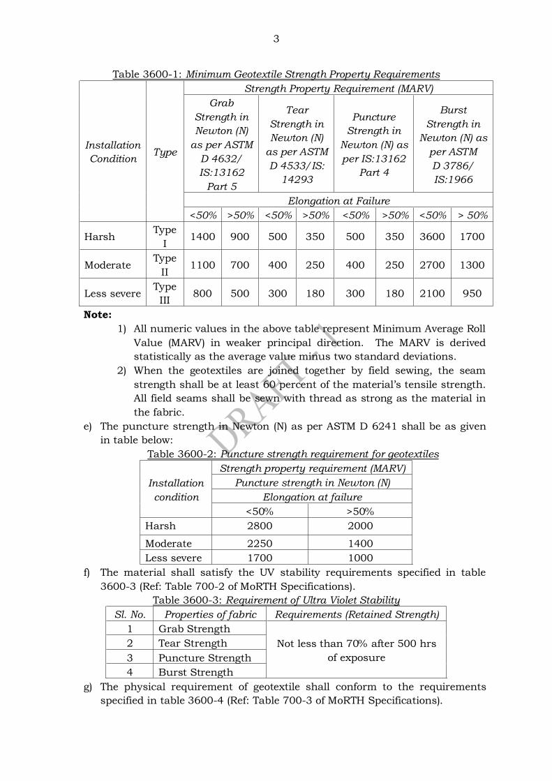
3
Table 3600-1: Minimum Geotextile Strength Property Requirements
Installation
Condition Type
Strength Property Requirement (MARV)
Grab
Strength in
Newton (N)
as per ASTM
D 4632/
IS:13162
Part 5
Tear
Strength in
Newton (N)
as per ASTM
D 4533/IS:
14293
Puncture
Strength in
Newton (N) as
per IS:13162
Part 4
Burst
Strength in
Newton (N) as
per ASTM
D 3786/
IS:1966
Elongation at Failure
<50% >50% <50% >50% <50% >50% <50% > 50%
Harsh Type
I 1400 900 500 350 500 350 3600 1700
Moderate Type
II 1100 700 400 250 400 250 2700 1300
Less severe Type
III 800 500 300 180 300 180 2100 950
Note:
1) All numeric values in the above table represent Minimum Average Roll
Value (MARV) in weaker principal direction. The MARV is derived
statistically as the average value minus two standard deviations.
2) When the geotextiles are joined together by field sewing, the seam
strength shall be at least 60 percent of the material’s tensile strength. All field seams shall be sewn with thread as strong as the material in
the fabric.
e) The puncture strength in Newton (N) as per ASTM D 6241 shall be as given
in table below:
Table 3600-2: Puncture strength requirement for geotextiles
Installation
condition
Strength property requirement (MARV)
Puncture strength in Newton (N)
Elongation at failure
<50% >50%
Harsh 2800 2000
Moderate 2250 1400
Less severe 1700 1000
f) The material shall satisfy the UV stability requirements specified in table
3600-3 (Ref: Table 700-2 of MoRTH Specifications).
Table 3600-3: Requirement of Ultra Violet Stability
Sl. No. Properties of fabric Requirements (Retained Strength)
1 Grab Strength
Not less than 70% after 500 hrs
of exposure
2 Tear Strength
3 Puncture Strength
4 Burst Strength
g) The physical requirement of geotextile shall conform to the requirements
specified in table 3600-4 (Ref: Table 700-3 of MoRTH Specifications).
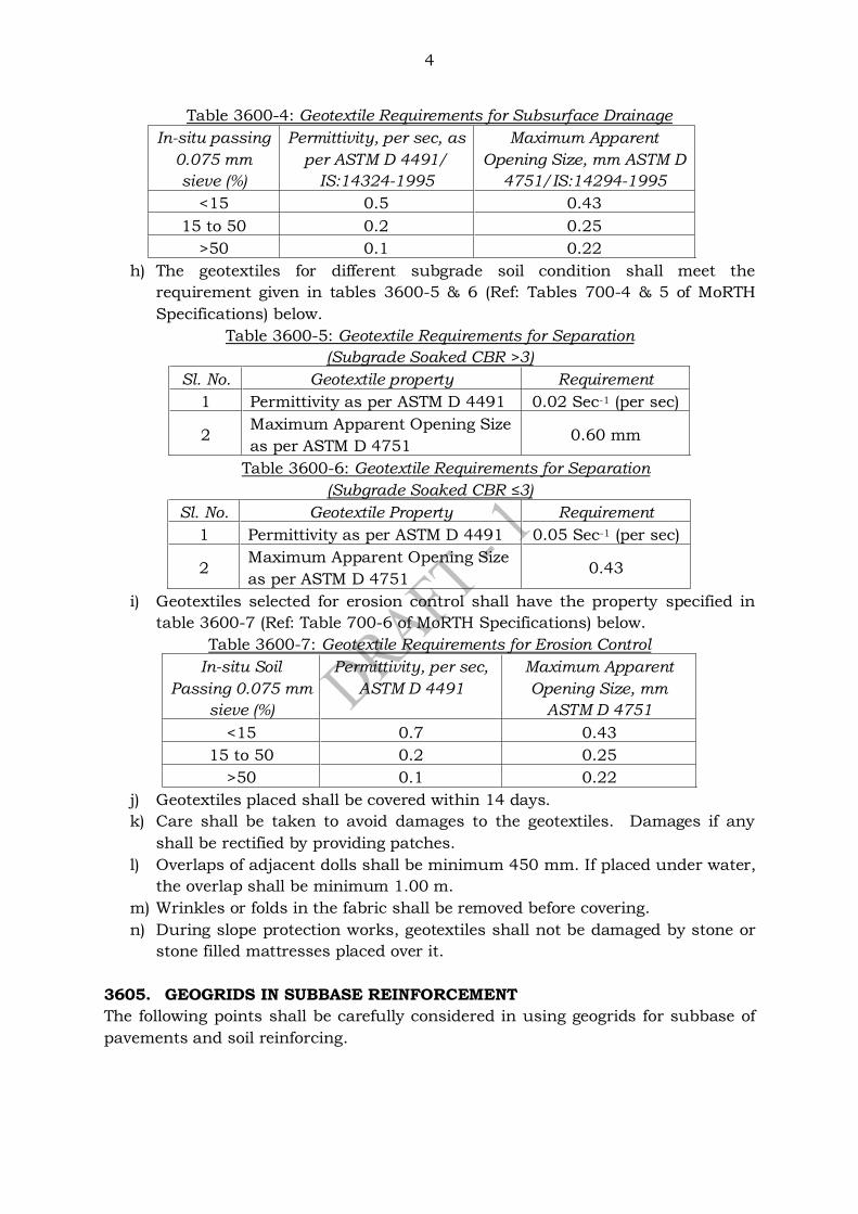
4
Table 3600-4: Geotextile Requirements for Subsurface Drainage
In-situ passing
0.075 mm
sieve (%)
Permittivity, per sec, as
per ASTM D 4491/
IS:14324-1995
Maximum Apparent
Opening Size, mm ASTM D
4751/IS:14294-1995
<15 0.5 0.43
15 to 50 0.2 0.25
>50 0.1 0.22
h) The geotextiles for different subgrade soil condition shall meet the
requirement given in tables 3600-5 & 6 (Ref: Tables 700-4 & 5 of MoRTH
Specifications) below.
Table 3600-5: Geotextile Requirements for Separation
(Subgrade Soaked CBR >3)
Sl. No. Geotextile property Requirement
1 Permittivity as per ASTM D 4491 0.02 Sec-1 (per sec)
2 Maximum Apparent Opening Size
as per ASTM D 4751 0.60 mm
Table 3600-6: Geotextile Requirements for Separation
(Subgrade Soaked CBR ≤3)
Sl. No. Geotextile Property Requirement
1 Permittivity as per ASTM D 4491 0.05 Sec-1 (per sec)
2 Maximum Apparent Opening Size
as per ASTM D 4751 0.43
i) Geotextiles selected for erosion control shall have the property specified in
table 3600-7 (Ref: Table 700-6 of MoRTH Specifications) below.
Table 3600-7: Geotextile Requirements for Erosion Control
In-situ Soil
Passing 0.075 mm
sieve (%)
Permittivity, per sec,
ASTM D 4491
Maximum Apparent
Opening Size, mm
ASTM D 4751
<15 0.7 0.43
15 to 50 0.2 0.25
>50 0.1 0.22
j) Geotextiles placed shall be covered within 14 days.
k) Care shall be taken to avoid damages to the geotextiles. Damages if any
shall be rectified by providing patches.
l) Overlaps of adjacent dolls shall be minimum 450 mm. If placed under water,
the overlap shall be minimum 1.00 m.
m) Wrinkles or folds in the fabric shall be removed before covering.
n) During slope protection works, geotextiles shall not be damaged by stone or
stone filled mattresses placed over it.
3605. GEOGRIDS IN SUBBASE REINFORCEMENT
The following points shall be carefully considered in using geogrids for subbase of
pavements and soil reinforcing.
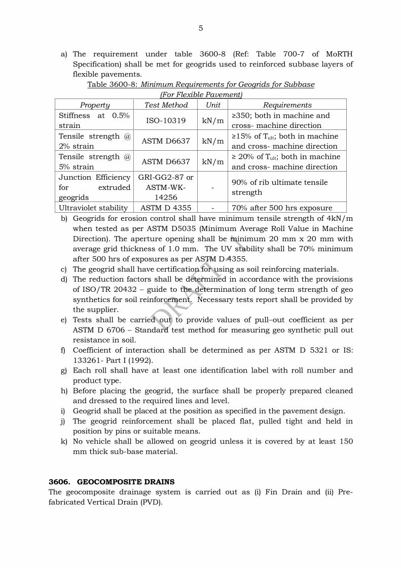
5
a) The requirement under table 3600-8 (Ref: Table 700-7 of MoRTH
Specification) shall be met for geogrids used to reinforced subbase layers of
flexible pavements.
Table 3600-8: Minimum Requirements for Geogrids for Subbase
(For Flexible Pavement)
Property Test Method Unit Requirements
Stiffness at 0.5%
strain ISO-10319 kN/m
≥350; both in machine and
cross- machine direction
Tensile strength @
2% strain ASTM D6637 kN/m
≥15% of Tult; both in machine
and cross- machine direction
Tensile strength @
5% strain ASTM D6637 kN/m
≥ 20% of Tult; both in machine
and cross- machine direction
Junction Efficiency
for extruded
geogrids
GRI-GG2-87 or
ASTM-WK-
14256
- 90% of rib ultimate tensile
strength
Ultraviolet stability ASTM D 4355 - 70% after 500 hrs exposure
b) Geogrids for erosion control shall have minimum tensile strength of 4kN/m
when tested as per ASTM D5035 (Minimum Average Roll Value in Machine
Direction). The aperture opening shall be minimum 20 mm x 20 mm with
average grid thickness of 1.0 mm. The UV stability shall be 70% minimum
after 500 hrs of exposures as per ASTM D 4355.
c) The geogrid shall have certification for using as soil reinforcing materials.
d) The reduction factors shall be determined in accordance with the provisions
of ISO/TR 20432 – guide to the determination of long term strength of geo
synthetics for soil reinforcement. Necessary tests report shall be provided by
the supplier.
e) Tests shall be carried out to provide values of pull–out coefficient as per
ASTM D 6706 – Standard test method for measuring geo synthetic pull out
resistance in soil.
f) Coefficient of interaction shall be determined as per ASTM D 5321 or IS:
133261- Part I (1992).
g) Each roll shall have at least one identification label with roll number and
product type.
h) Before placing the geogrid, the surface shall be properly prepared cleaned
and dressed to the required lines and level.
i) Geogrid shall be placed at the position as specified in the pavement design.
j) The geogrid reinforcement shall be placed flat, pulled tight and held in
position by pins or suitable means.
k) No vehicle shall be allowed on geogrid unless it is covered by at least 150
mm thick sub-base material.
3606. GEOCOMPOSITE DRAINS
The geocomposite drainage system is carried out as (i) Fin Drain and (ii) Pre-
fabricated Vertical Drain (PVD).

6
3506.1 Fin Drains
The Fin drains are made of light weight three dimensional high compressive
strength polyethylene core and heat bounded or needle punched
polyethylene/polyester geotextiles provided in one or both sides of the core as
required.
The following points shall be looked into while supply and installing fine drains.
a) The requirements of geotextile used in compote drainage system shall meet
the requirements specified in table 3600-9 (Ref: Table 700-9 of MoRTH
Specifications) given below.
Table 3600-9: Geotextile Requirements for Fin Drains
In-situ Soil
Passing 0.075 mm
sieve (%)
Permittivity, per sec
ASTM D 4491/
IS:14324-1995
Maximum Apparent Opening
Size, mm as per ASTM D
4751/ IS:14294-1995
<15 0.5 0.43
15 to 50 0.2 0.25
>50 0.1 0.22
b) The core material shall meet the requirements given under table 3600-10
(Ref: Table 700-10 of MoRTH Specifications).
Table 3600-10: Properties for Fin Drain Core
Property Test Method Units
Minimum
Average
Roll Value
Tensile strength EN ISO-10319 kN/m 16
CBR Puncture Resistance EN ISO-12236 N 3000
Mass per unit area EN ISO-9864 g/m2 710
Thickness of composite EN ISO-9863 mm 4.5
In–plane
permeability
Hydraulic Gradient, i
=1 at 100 kPa pressure EN ISO-12958 l/m 0.55
Hydraulic Gradient, i
=1 at 200 kPa pressure 0.45
3606.2 Prefabricated Vertical Drains (PVDs)/Band Drains
The design and construction of Prefabricated Vertical Drains PVD) shall generally
be done in accordance with IS: 15284 (Part 2). The specification of materials and
construction requirements are given under Clause 314 of MoRTH Specifications.
Following points shall be considered in improving the ground condition using
geosynthetic drains (Prefabricated Vertical Drain).
a) Geosynthetic strip or band drain shall be manufactured by an ISO 9001
certified manufacturer.
b) Band drains shall be of a minimum with of 100 mm and thickness 5 mm.
c) The core made of polyester or equivalent material serve as the drainage
medium conveying core water for sub soil to the drainage layer at top.
d) The filter shall be made of non-woven needle punched adhesive bounded
fabric.
e) The filter and core shall be ultrasonically welded together at edges to
produce a full integrated product.
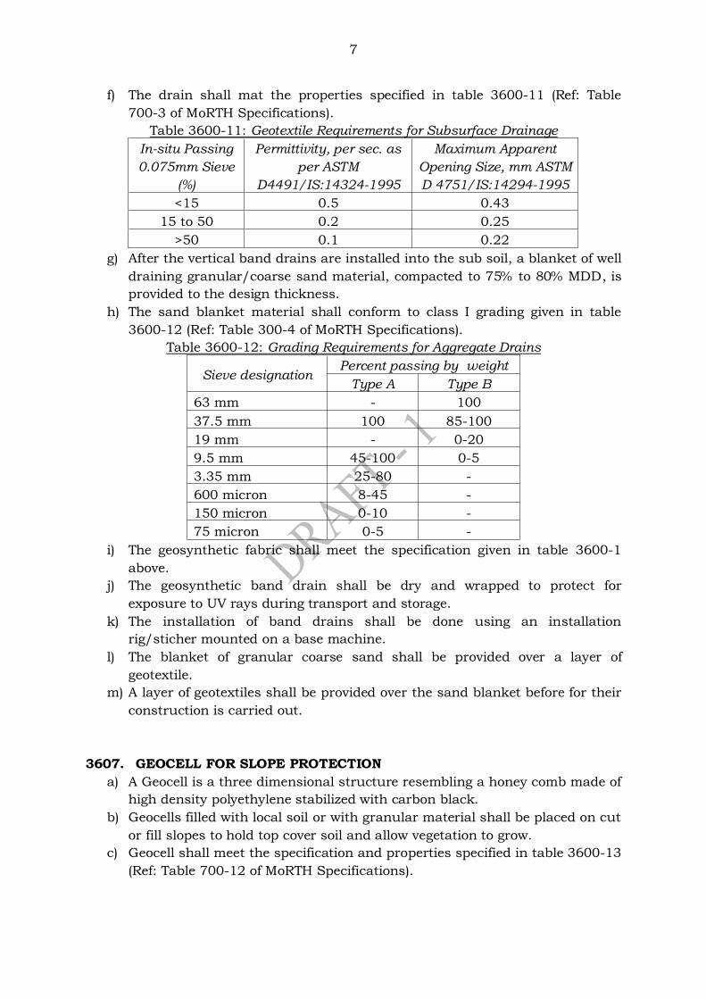
7
f) The drain shall mat the properties specified in table 3600-11 (Ref: Table
700-3 of MoRTH Specifications).
Table 3600-11: Geotextile Requirements for Subsurface Drainage
In-situ Passing
0.075mm Sieve
(%)
Permittivity, per sec. as
per ASTM
D4491/IS:14324-1995
Maximum Apparent
Opening Size, mm ASTM
D 4751/IS:14294-1995
<15 0.5 0.43
15 to 50 0.2 0.25
>50 0.1 0.22
g) After the vertical band drains are installed into the sub soil, a blanket of well
draining granular/coarse sand material, compacted to 75% to 80% MDD, is
provided to the design thickness.
h) The sand blanket material shall conform to class I grading given in table
3600-12 (Ref: Table 300-4 of MoRTH Specifications).
Table 3600-12: Grading Requirements for Aggregate Drains
Sieve designation Percent passing by weight
Type A Type B
63 mm - 100
37.5 mm 100 85-100
19 mm - 0-20
9.5 mm 45-100 0-5
3.35 mm 25-80 -
600 micron 8-45 -
150 micron 0-10 -
75 micron 0-5 -
i) The geosynthetic fabric shall meet the specification given in table 3600-1
above.
j) The geosynthetic band drain shall be dry and wrapped to protect for
exposure to UV rays during transport and storage.
k) The installation of band drains shall be done using an installation
rig/sticher mounted on a base machine.
l) The blanket of granular coarse sand shall be provided over a layer of
geotextile.
m) A layer of geotextiles shall be provided over the sand blanket before for their
construction is carried out.
3607. GEOCELL FOR SLOPE PROTECTION
a) A Geocell is a three dimensional structure resembling a honey comb made of
high density polyethylene stabilized with carbon black.
b) Geocells filled with local soil or with granular material shall be placed on cut
or fill slopes to hold top cover soil and allow vegetation to grow.
c) Geocell shall meet the specification and properties specified in table 3600-13
(Ref: Table 700-12 of MoRTH Specifications).
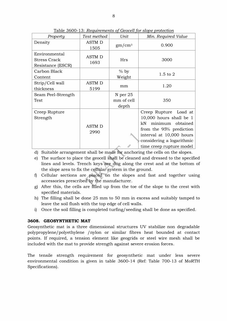
8
Table 3600-13: Requirements of Geocell for slope protection
Property Test method Unit Min. Required Value
Density ASTM D
1505 gm/cm3 0.900
Environmental
Stress Crack
Resistance (ESCR)
ASTM D
1693 Hrs 3000
Carbon Black
Content
% by
Weight 1.5 to 2
Strip/Cell wall
thickness
ASTM D
5199 mm 1.20
Seam Peel-Strength
Test
N per 25
mm of cell
depth
350
Creep Rupture
Strength
ASTM D
2990
Creep Rupture Load at
10,000 hours shall be 1
kN minimum obtained
from the 95% prediction
interval at 10,000 hours
considering a logarithmic
time creep rupture model
d) Suitable arrangement shall be made for anchoring the cells on the slopes.
e) The surface to place the geocell shall be cleaned and dressed to the specified
lines and levels. Trench keys are dug along the crest and at the bottom of
the slope area to fix the cellular system in the ground.
f) Cellular sections are placed on the slopes and fast and together using
accessories prescribed by the manufacturer.
g) After this, the cells are filled up from the toe of the slope to the crest with
specified materials.
h) The filling shall be done 25 mm to 50 mm in excess and suitably tamped to
leave the soil flush with the top edge of cell walls.
i) Once the soil filling is completed turfing/seeding shall be done as specified.
3608. GEOSYNTHETIC MAT
Geosynthetic mat is a three dimensional structures UV stabilize non degradable
polypropylene/polyethylene /nylon or similar fibres heat bounded at contact
points. If required, a tension element like geogrids or steel wire mesh shall be
included with the mat to provide strength against severe erosion forces.
The tensile strength requirement for geosynthetic mat under less severe
environmental condition is given in table 3600-14 (Ref: Table 700-13 of MoRTH
Specifications).
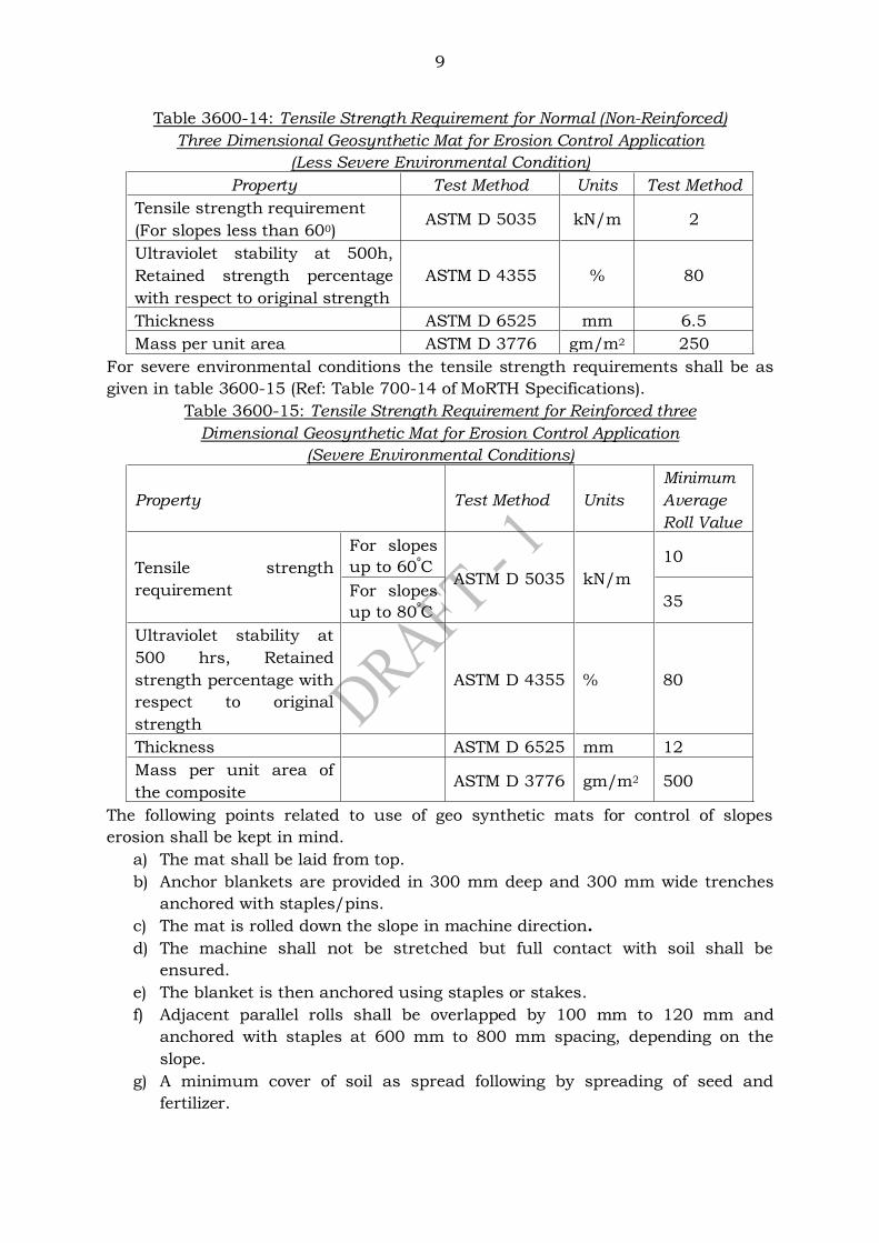
9
Table 3600-14: Tensile Strength Requirement for Normal (Non-Reinforced)
Three Dimensional Geosynthetic Mat for Erosion Control Application
(Less Severe Environmental Condition)
Property Test Method Units Test Method
Tensile strength requirement
(For slopes less than 600) ASTM D 5035 kN/m 2
Ultraviolet stability at 500h,
Retained strength percentage
with respect to original strength
ASTM D 4355 % 80
Thickness ASTM D 6525 mm 6.5
Mass per unit area ASTM D 3776 gm/m2 250
For severe environmental conditions the tensile strength requirements shall be as
given in table 3600-15 (Ref: Table 700-14 of MoRTH Specifications).
Table 3600-15: Tensile Strength Requirement for Reinforced three
Dimensional Geosynthetic Mat for Erosion Control Application
(Severe Environmental Conditions)
Property Test Method Units
Minimum
Average
Roll Value
Tensile strength
requirement
For slopes
up to 60⁰C ASTM D 5035 kN/m
10
For slopes
up to 80⁰C 35
Ultraviolet stability at
500 hrs, Retained
strength percentage with
respect to original
strength
ASTM D 4355 % 80
Thickness ASTM D 6525 mm 12
Mass per unit area of
the composite ASTM D 3776 gm/m2 500
The following points related to use of geo synthetic mats for control of slopes
erosion shall be kept in mind.
a) The mat shall be laid from top.
b) Anchor blankets are provided in 300 mm deep and 300 mm wide trenches
anchored with staples/pins.
c) The mat is rolled down the slope in machine direction.
d) The machine shall not be stretched but full contact with soil shall be
ensured.
e) The blanket is then anchored using staples or stakes.
f) Adjacent parallel rolls shall be overlapped by 100 mm to 120 mm and
anchored with staples at 600 mm to 800 mm spacing, depending on the
slope.
g) A minimum cover of soil as spread following by spreading of seed and
fertilizer.
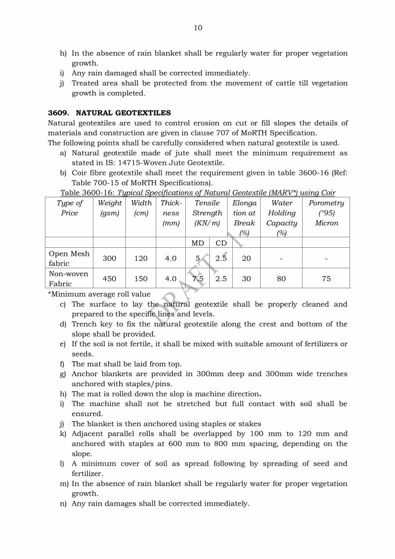
10
h) In the absence of rain blanket shall be regularly water for proper vegetation
growth.
i) Any rain damaged shall be corrected immediately.
j) Treated area shall be protected from the movement of cattle till vegetation
growth is completed.
3609. NATURAL GEOTEXTILES
Natural geotextiles are used to control erosion on cut or fill slopes the details of
materials and construction are given in clause 707 of MoRTH Specification.
The following points shall be carefully considered when natural geotextile is used.
a) Natural geotextile made of jute shall meet the minimum requirement as
stated in IS: 14715-Woven Jute Geotextile.
b) Coir fibre geotextile shall meet the requirement given in table 3600-16 (Ref:
Table 700-15 of MoRTH Specifications).
Table 3600-16: Typical Specifications of Natural Geotextile (MARV*) using Coir
Type of
Price
Weight
(gsm)
Width
(cm)
Thick-
ness
(mm)
Tensile
Strength
(KN/m)
Elonga
tion at
Break
(%)
Water
Holding
Capacity
(%)
Porometry
(°95)
Micron
MD CD
Open Mesh
fabric 300 120 4.0 5 2.5 20 - -
Non-woven
Fabric 450 150 4.0 7.5 2.5 30 80 75
*Minimum average roll value
c) The surface to lay the natural geotextile shall be properly cleaned and
prepared to the specific lines and levels.
d) Trench key to fix the natural geotextile along the crest and bottom of the
slope shall be provided.
e) If the soil is not fertile, it shall be mixed with suitable amount of fertilizers or
seeds.
f) The mat shall be laid from top.
g) Anchor blankets are provided in 300mm deep and 300mm wide trenches
anchored with staples/pins.
h) The mat is rolled down the slop is machine direction.
i) The machine shall not be stretched but full contact with soil shall be
ensured.
j) The blanket is then anchored using staples or stakes
k) Adjacent parallel rolls shall be overlapped by 100 mm to 120 mm and
anchored with staples at 600 mm to 800 mm spacing, depending on the
slope.
l) A minimum cover of soil as spread following by spreading of seed and
fertilizer.
m) In the absence of rain blanket shall be regularly water for proper vegetation
growth.
n) Any rain damages shall be corrected immediately.
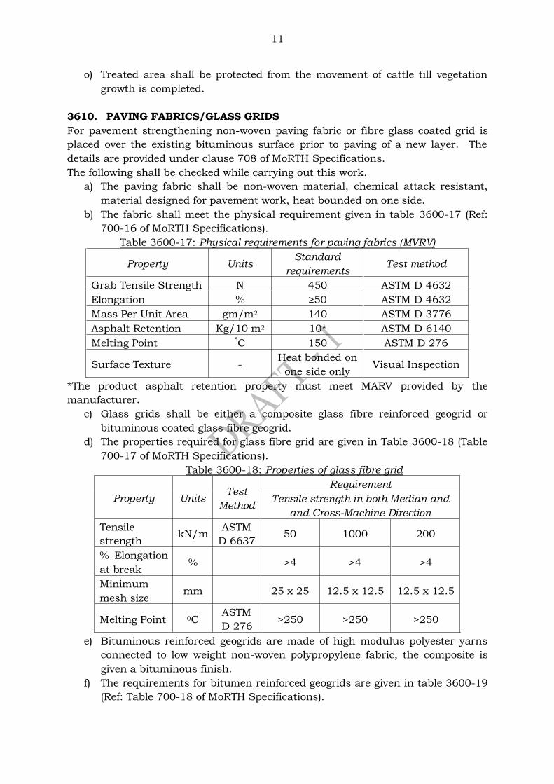
11
o) Treated area shall be protected from the movement of cattle till vegetation
growth is completed.
3610. PAVING FABRICS/GLASS GRIDS
For pavement strengthening non-woven paving fabric or fibre glass coated grid is
placed over the existing bituminous surface prior to paving of a new layer. The
details are provided under clause 708 of MoRTH Specifications.
The following shall be checked while carrying out this work.
a) The paving fabric shall be non-woven material, chemical attack resistant,
material designed for pavement work, heat bounded on one side.
b) The fabric shall meet the physical requirement given in table 3600-17 (Ref:
700-16 of MoRTH Specifications).
Table 3600-17: Physical requirements for paving fabrics (MVRV)
Property Units Standard
requirements Test method
Grab Tensile Strength N 450 ASTM D 4632
Elongation % ≥50 ASTM D 4632
Mass Per Unit Area gm/m2 140 ASTM D 3776
Asphalt Retention Kg/10 m2 10* ASTM D 6140
Melting Point °C 150 ASTM D 276
Surface Texture - Heat bonded on
one side only Visual Inspection
*The product asphalt retention property must meet MARV provided by the
manufacturer.
c) Glass grids shall be either a composite glass fibre reinforced geogrid or
bituminous coated glass fibre geogrid.
d) The properties required for glass fibre grid are given in Table 3600-18 (Table
700-17 of MoRTH Specifications).
Table 3600-18: Properties of glass fibre grid
Property Units Test
Method
Requirement
Tensile strength in both Median and
and Cross-Machine Direction
Tensile
strength kN/m
ASTM
D 6637 50 1000 200
% Elongation
at break % >4 >4 >4
Minimum
mesh size mm 25 x 25 12.5 x 12.5 12.5 x 12.5
Melting Point 0C ASTM
D 276 >250 >250 >250
e) Bituminous reinforced geogrids are made of high modulus polyester yarns
connected to low weight non-woven polypropylene fabric, the composite is
given a bituminous finish.
f) The requirements for bitumen reinforced geogrids are given in table 3600-19
(Ref: Table 700-18 of MoRTH Specifications).
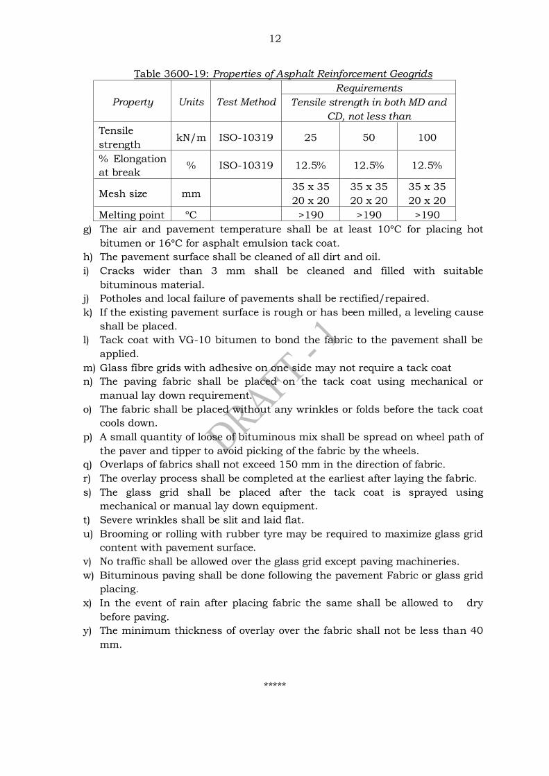
12
Table 3600-19: Properties of Asphalt Reinforcement Geogrids
Property Units Test Method
Requirements
Tensile strength in both MD and
CD, not less than
Tensile
strength kN/m ISO-10319 25 50 100
% Elongation
at break % ISO-10319 12.5% 12.5% 12.5%
Mesh size mm 35 x 35
20 x 20
35 x 35
20 x 20
35 x 35
20 x 20
Melting point °C >190 >190 >190
g) The air and pavement temperature shall be at least 10°C for placing hot
bitumen or 16°C for asphalt emulsion tack coat.
h) The pavement surface shall be cleaned of all dirt and oil.
i) Cracks wider than 3 mm shall be cleaned and filled with suitable
bituminous material.
j) Potholes and local failure of pavements shall be rectified/repaired.
k) If the existing pavement surface is rough or has been milled, a leveling cause
shall be placed.
l) Tack coat with VG-10 bitumen to bond the fabric to the pavement shall be
applied.
m) Glass fibre grids with adhesive on one side may not require a tack coat
n) The paving fabric shall be placed on the tack coat using mechanical or
manual lay down requirement.
o) The fabric shall be placed without any wrinkles or folds before the tack coat
cools down.
p) A small quantity of loose of bituminous mix shall be spread on wheel path of
the paver and tipper to avoid picking of the fabric by the wheels.
q) Overlaps of fabrics shall not exceed 150 mm in the direction of fabric.
r) The overlay process shall be completed at the earliest after laying the fabric.
s) The glass grid shall be placed after the tack coat is sprayed using
mechanical or manual lay down equipment.
t) Severe wrinkles shall be slit and laid flat.
u) Brooming or rolling with rubber tyre may be required to maximize glass grid
content with pavement surface.
v) No traffic shall be allowed over the glass grid except paving machineries.
w) Bituminous paving shall be done following the pavement Fabric or glass grid
placing.
x) In the event of rain after placing fabric the same shall be allowed to dry
before paving.
y) The minimum thickness of overlay over the fabric shall not be less than 40
mm.
*****
Confidential - For private circulation only
SECTION 3700: ROAD DRAINAGE
CONTENTS
3701 GENERAL
3702 NEED FOR A DRAINAGE SYSTEM
3703 TYPES OF ROAD DRAINAGE
3704 INVESTIGATIONS FOR ROAD DRAINAGE
3705 SURFACE DRAINS
3705.1 Road Side Drains
3705.1.2 Lining of side drain
3705.2 Shoulder drains
3706 CATCH WATER DRAIN
3707 SUBSURFACE DRAINS
3707.1 Perforated pipe drains
3707.2 Aggregate drains
3707.3 Subsurface drains in other areas
*****

1
SECTION 3700: ROAD DRAINAGE
3701 GENERAL
An effective drainage system is required to prevent damages to pavement, caused
due to saturation of the subgrade or fill immediately below and to minimise access
of water into the pavement layers. The road drainage should be effective in
disposing the surface precipitation and controlling the underground seepage. For
the design of drains, the Indian Roads Congress publications IRC: SP: 42 & SP: 50
can be referred.
Damages caused to the road by inadequate drainage are:
a) Reduction in bearing capacity of the subgrade soil due to the presence of
water, leading to complete failure of the pavement.
b) Reduction in the design strength of pavement layers such as stabilized soil,
water bound macadam etc due to the ingress of water.
c) Potholes, rutting, waviness and corrugation of the bituminous pavement
layers.
d) Erosion of shoulder and pavement edges due to the flow of surface water.
e) Loss of soil from the subgrade and fill layers below the pavement due to
seepage of water.
f) Erosion of slopes of fill/cut or hillside due to surface water.
3702 NEED FOR A DRAINAGE SYSTEM
a) It has been established by studies that cost of maintenance/repair of a road
can be reduced considerably, if proper drainage is provided.
b) Drainage is essential for ensuring the structural and functional adequacy of
the road.
c) Providing drainage measures at a later stage is both difficult and expensive.
Hence provisions for adequate drainage shall be made at the initial phase of
constructions.
3703 TYPES OF ROAD DRAINAGE
The road drainage works are broadly classified under (i) surface drainage and (ii)
subsurface drainage.
Surface drainage deals with the interception of surface water or storm water.
Subsurface drainage is for the removal of seepage or subsurface water. Internal
drainage of pavement may be required, if the annual rain fall of the area is more
than 500 mm.
3704 INVESTIGATIONS FOR ROAD DRAINAGE
For designing an efficient drainage system, a detailed survey and field investigation
should be carried out. The following features are required for drainage design:
a) Preparation of alignment plan, longitudinal section, contour plan etc.
b) Hydrological data, such as rainfall, calculations of runoff etc.
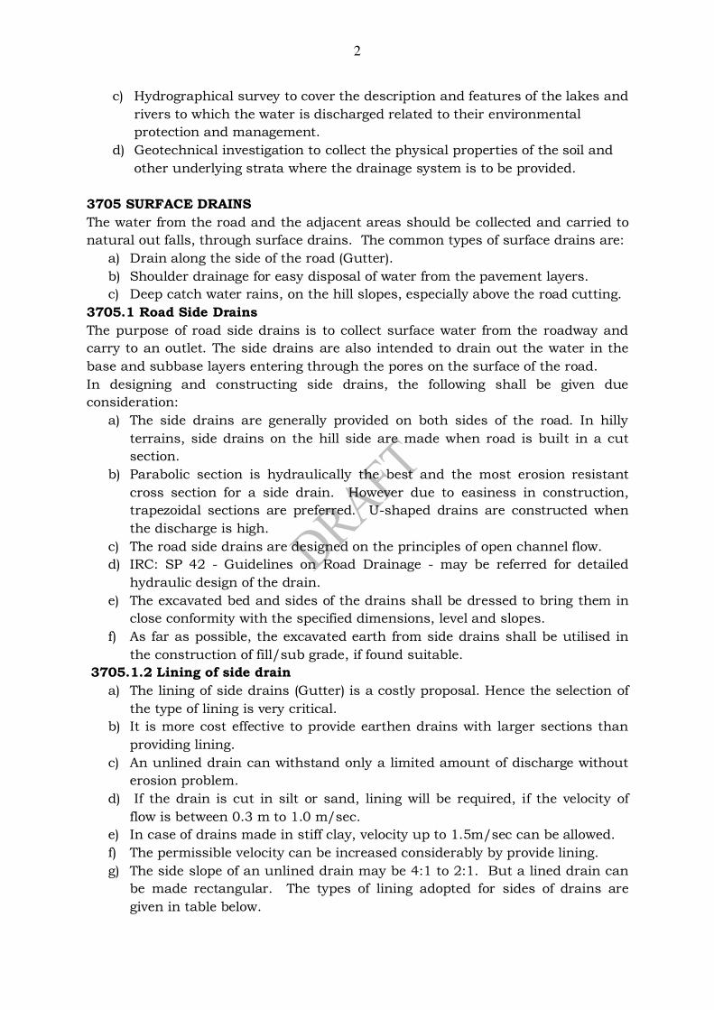
2
c) Hydrographical survey to cover the description and features of the lakes and
rivers to which the water is discharged related to their environmental
protection and management.
d) Geotechnical investigation to collect the physical properties of the soil and
other underlying strata where the drainage system is to be provided.
3705 SURFACE DRAINS
The water from the road and the adjacent areas should be collected and carried to
natural out falls, through surface drains. The common types of surface drains are:
a) Drain along the side of the road (Gutter).
b) Shoulder drainage for easy disposal of water from the pavement layers.
c) Deep catch water rains, on the hill slopes, especially above the road cutting.
3705.1 Road Side Drains
The purpose of road side drains is to collect surface water from the roadway and
carry to an outlet. The side drains are also intended to drain out the water in the
base and subbase layers entering through the pores on the surface of the road.
In designing and constructing side drains, the following shall be given due
consideration:
a) The side drains are generally provided on both sides of the road. In hilly
terrains, side drains on the hill side are made when road is built in a cut
section.
b) Parabolic section is hydraulically the best and the most erosion resistant
cross section for a side drain. However due to easiness in construction,
trapezoidal sections are preferred. U-shaped drains are constructed when
the discharge is high.
c) The road side drains are designed on the principles of open channel flow.
d) IRC: SP 42 - Guidelines on Road Drainage - may be referred for detailed
hydraulic design of the drain.
e) The excavated bed and sides of the drains shall be dressed to bring them in
close conformity with the specified dimensions, level and slopes.
f) As far as possible, the excavated earth from side drains shall be utilised in
the construction of fill/sub grade, if found suitable.
3705.1.2 Lining of side drain
a) The lining of side drains (Gutter) is a costly proposal. Hence the selection of
the type of lining is very critical.
b) It is more cost effective to provide earthen drains with larger sections than
providing lining.
c) An unlined drain can withstand only a limited amount of discharge without
erosion problem.
d) If the drain is cut in silt or sand, lining will be required, if the velocity of
flow is between 0.3 m to 1.0 m/sec.
e) In case of drains made in stiff clay, velocity up to 1.5m/sec can be allowed.
f) The permissible velocity can be increased considerably by provide lining.
g) The side slope of an unlined drain may be 4:1 to 2:1. But a lined drain can
be made rectangular. The types of lining adopted for sides of drains are
given in table below.
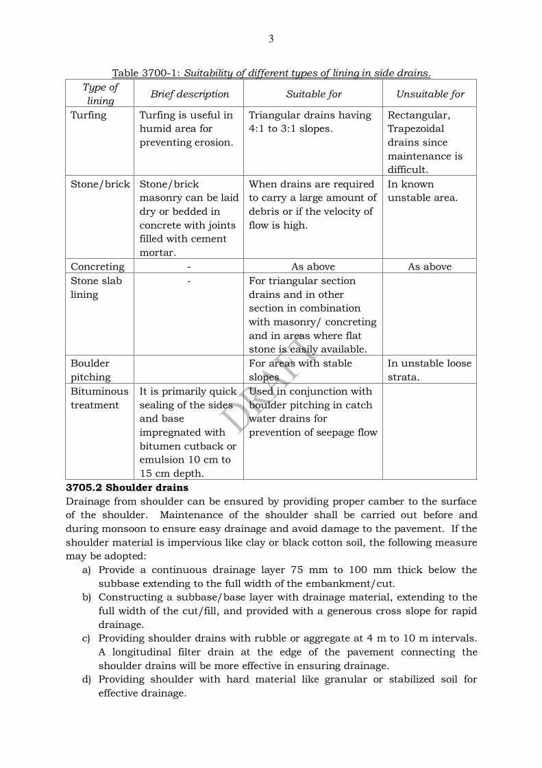
3
Table 3700-1: Suitability of different types of lining in side drains.
Type of
lining Brief description Suitable for Unsuitable for
Turfing Turfing is useful in
humid area for
preventing erosion.
Triangular drains having
4:1 to 3:1 slopes.
Rectangular,
Trapezoidal
drains since
maintenance is
difficult.
Stone/brick Stone/brick
masonry can be laid
dry or bedded in
concrete with joints
filled with cement
mortar.
When drains are required
to carry a large amount of
debris or if the velocity of
flow is high.
In known
unstable area.
Concreting - As above As above
Stone slab
lining
- For triangular section
drains and in other
section in combination
with masonry/ concreting
and in areas where flat
stone is easily available.
Boulder
pitching
For areas with stable
slopes
In unstable loose
strata.
Bituminous
treatment
It is primarily quick
sealing of the sides
and base
impregnated with
bitumen cutback or
emulsion 10 cm to
15 cm depth.
Used in conjunction with
boulder pitching in catch
water drains for
prevention of seepage flow
3705.2 Shoulder drains
Drainage from shoulder can be ensured by providing proper camber to the surface
of the shoulder. Maintenance of the shoulder shall be carried out before and
during monsoon to ensure easy drainage and avoid damage to the pavement. If the
shoulder material is impervious like clay or black cotton soil, the following measure
may be adopted:
a) Provide a continuous drainage layer 75 mm to 100 mm thick below the
subbase extending to the full width of the embankment/cut.
b) Constructing a subbase/base layer with drainage material, extending to the
full width of the cut/fill, and provided with a generous cross slope for rapid
drainage.
c) Providing shoulder drains with rubble or aggregate at 4 m to 10 m intervals.
A longitudinal filter drain at the edge of the pavement connecting the
shoulder drains will be more effective in ensuring drainage.
d) Providing shoulder with hard material like granular or stabilized soil for
effective drainage.
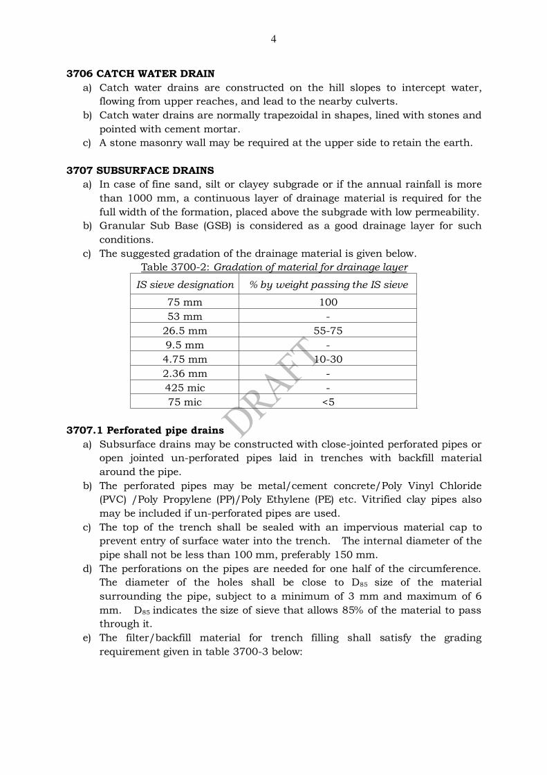
4
3706 CATCH WATER DRAIN
a) Catch water drains are constructed on the hill slopes to intercept water,
flowing from upper reaches, and lead to the nearby culverts.
b) Catch water drains are normally trapezoidal in shapes, lined with stones and
pointed with cement mortar.
c) A stone masonry wall may be required at the upper side to retain the earth.
3707 SUBSURFACE DRAINS
a) In case of fine sand, silt or clayey subgrade or if the annual rainfall is more
than 1000 mm, a continuous layer of drainage material is required for the
full width of the formation, placed above the subgrade with low permeability.
b) Granular Sub Base (GSB) is considered as a good drainage layer for such
conditions.
c) The suggested gradation of the drainage material is given below.
Table 3700-2: Gradation of material for drainage layer
IS sieve designation % by weight passing the IS sieve
75 mm 100
53 mm -
26.5 mm 55-75
9.5 mm -
4.75 mm 10-30
2.36 mm -
425 mic -
75 mic <5
3707.1 Perforated pipe drains
a) Subsurface drains may be constructed with close-jointed perforated pipes or
open jointed un-perforated pipes laid in trenches with backfill material
around the pipe.
b) The perforated pipes may be metal/cement concrete/Poly Vinyl Chloride
(PVC) /Poly Propylene (PP)/Poly Ethylene (PE) etc. Vitrified clay pipes also
may be included if un-perforated pipes are used.
c) The top of the trench shall be sealed with an impervious material cap to
prevent entry of surface water into the trench. The internal diameter of the
pipe shall not be less than 100 mm, preferably 150 mm.
d) The perforations on the pipes are needed for one half of the circumference.
The diameter of the holes shall be close to D85 size of the material
surrounding the pipe, subject to a minimum of 3 mm and maximum of 6
mm. D85 indicates the size of sieve that allows 85% of the material to pass
through it.
e) The filter/backfill material for trench filling shall satisfy the grading
requirement given in table 3700-3 below:

5
Table 3700-3: Grading requirement for filter material
IS Sieve
designation
% by weight passing the IS sieve
Class I Class II Class III
53 mm - - 100
45 mm - - 97-100
26.5 mm - 100 -
22.4 mm - 95-100 50-100
11.2 mm 100 48-100 20-60
5.6 mm 92-100 28-54 4-32
2.8 mm 83-100 20-35 0-10
1.4 mm 59-96 - 1-5
710 mm 35-80 6-18 -
355 µm 14-40 2-9 -
180 µm 3-15 - -
90 µm 0-5 0-4 0-3
f) The thickness of backfill around the pipe shall not be less than150 mm, and
the minimum trench width shall be 450 mm.
g) The laying of pipe shall start from the outlet end and proceed towards the
upper end.
h) The thickness of backfill material shall be 150 mm minimum, below the
pipe. The minimum thickness of backfill above pipe shall be 300 mm.
i) The perforations shall be placed down, while laying, to minimize clogging.
3707.2 Aggregate drains
The subsurface drains may be also constructed without using pipes. The trench
may be filled with material such as gravel, slag or stone aggregates free from
organic or deleterious substances. Such drains are knows as aggregate drains.
a) The aggregates drains shall be placed within the verge/shoulders after
completion of the pavement.
b) The trenches for aggregates drains shall be 300 mm width, minimum.
c) The suggested grading of backfill material for aggregates drains is given in
table 3700-4 below.
Table 3700-4: Gradation for backfill material aggregate drain
IS sieve designation % by weight passing
13.2 mm 100
11.2 mm 92-100
5.6 mm 27-46
2.8 mm 3-16
1.4 mm 0-6
d) Geo-textiles are incorporated in subsurface drains either along the trench or
around the pipe or both to extent the life of the drainage system.
e) The minimum overlap of filter fabric shall be 450 mm.
3707.3 Subsurface drains in other areas
Accumulation of moisture in the slopes of hill or road cut can lead to land slides.
To facilitate quick drainage, perforated pipes are inserted horizontally on hill cuts
and thus increase the stability of the slope.

6
In valley curves, subsoil drainage can be improved by providing an aggregate drain
below the subbase layer to the full width of the formation. This type of sub surface
drains can be adopted when pavement is to be constructed in areas susceptible to
ingress of water.
REFERENCES:
1. IRC: SP: 20-Rural Roads Manual - Published by Indian Road Congress, New
Delhi 2002.
2. Manual of Specifications and Standards for two lining of Highways through
PPP - Published by the Planning Commission, Government of India.
*****