Embed Size (px)
Citation preview
KENTUCKY TRANSPORTATION CENTER
HIGHWAY-RAILWAY AT-GRADE CROSSING STRUCTURES:
OPTIMUM DESIGN/INSTALLATION PRACTICES AND
MANAGEMENT PROGRAM - AN OVERVIEW
Research ReportKTC-09-04/FR136-04-1F
We provide services to the transportation community
through research, technology transfer and education.
We create and participate in partnerships
to promote safe and effective
transportation systems.
OUR MISSION
OUR VALUES
Teamwork
Listening and communicating along with
courtesy and respect for others.
Honesty and Ethical Behavior
Delivering the highest quality
products and services.
Continuous Improvement
In all that we do.
i
Research Report
KTC-09-04/FR 136-04-1F
Highway-Railway At-Grade Crossing Structures:
Optimum Design/Installation Practices and
Management Program – An Overview
by
Jerry G. Rose Professor of Civil Engineering
ABSTRACT Replacing and rehabilitating highway-railway at-grade crossings represent major track maintenance expenses for the U.S. highway governmental agencies and railroad industry. The ideal crossing system is one that will maintain a smooth surface and stable highway/trackbed for a long period of time minimizing costly and inconvenient disruptions to highway and rail traffic.
This report describes the consensus goals for, and the development of, a cooperative, fast-track crossing renewal system for an ideal highway-railway crossing management program. The desired process utilizes premium structural materials and construction techniques to provide long-term, cost effective, smooth, and safe crossings. Specifically stressed is the desirability of using a high-modulus, waterproofing, structural layer composed of hot-mix asphalt.
Detailed descriptions are provided for several representative projects. These include typical installation processes, installation time studies, photographic documentations, and cost/economic evaluations. References are provided for Performance Measures that are documented in succeeding reports emanating from this project. These include 1) Trackbed and Surface Pressure Measurements, 2) Long-Term Settlement Measurements, 3) Rideability Measurements, and 4) Interfacial Surface Pressure Measurements.
Keywords: Highway-Railway Crossing Management, At-Grade Crossings, Railway Crossing Rehabilitation, Cooperative Fast-Track Crossing Renewal System, Asphalt Underlayment Trackbed Crossings
May 2009
1. Report No. KTC-09-04/FR 136-04-1F
2. Government Accession No.
3. Recipient’s Catalog No
4. Title and Subtitle
Highway-Railway At-Grade Crossing Structures: Optimum Design/Installation Practices and Management Program – An Overview
5. Report Date May 2009 6. Performing Organization Code
7. Author(s) Jerry G. Rose
8. Performing Organization Report No. KTC-09-04
9. Performing Organization Name and Address
Kentucky Transportation Center College of Engineering University of Kentucky Lexington, KY 40506-0281
10. Work Unit No. (TRAIS)
11. Contract or Grant No. FRT 136
12. Sponsoring Agency Name and Address
Kentucky Transportation Cabinet 200 Mero Street Frankfort, KY 4062
13. Type of Report and Period Covered
Final Report – KTC -09-04 7/1/2004 – 6/30/09 14. Sponsoring Agency Code
15. Supplementary Notes
Prepared in cooperation with the Kentucky Transportation Cabinet and the United States Department of Transportation, Federal Highway Administration
16. Abstract Replacing and rehabilitating highway-railway at-grade crossings represent major track maintenance expenses for the U.S. highway governmental agencies and railroad industry. The ideal crossing system is one that will maintain a smooth surface and stable highway/trackbed for a long period of time minimizing costly and inconvenient disruptions to highway and rail traffic. This report describes the consensus goals for, and the development of, a cooperative, fast-track crossing renewal system for an ideal highway-railway crossing management program. The performance-based process utilizes premium structural materials and construction techniques to provide long-term, cost effective, smooth, and safe crossings. Specifically stressed is the desirability of using a high-modulus, waterproofing, structural layer composed of hot-mix asphalt. Detailed descriptions are provided for several representative projects. These include typical installation processes, installation time studies, photographic documentations, and cost/economic evaluations. References are provided for Performance Measures that are documented in succeeding reports emanating from this project. These include 1) Trackbed and Surface Pressure Measurements, 2) Long-Term Settlement Measurements, 3) Rideability Measurements, and 4) Interfacial Surface Pressure Measurements. 17. Key Words Highway-Railway Crossing Management, At-Grade Crossings, Railway Crossing Rehabilitation, Cooperative Fast-Track Crossing Renewal System, Asphalt Underlayment Trackbed Crossings
18. Distribution Statement Unlimited, with the approval of the Kentucky Transportation Cabinet
19. Security Classif. (of this report) Unclassified
20. Security Classif. (of this page) Unclassified
21. No. of Pages 39 w/o appendix
22. Price
Form DOT F 1700.7 (8-72)
ii
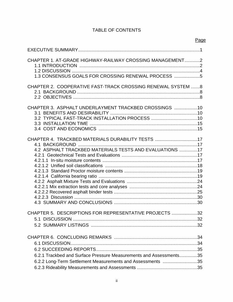
TABLE OF CONTENTS
Page
EXECUTIVE SUMMARY ............................................................................................... 1 CHAPTER 1. AT-GRADE HIGHWAY-RAILWAY CROSSING MANAGEMENT ............ 2
1.1 INTRODUCTION .............................................................................................. 2 1.2 DISCUSSION .................................................................................................... 4 1.3 CONSENSUS GOALS FOR CROSSING RENEWAL PROCESS .................... 5
CHAPTER 2. COOPERATIVE FAST-TRACK CROSSING RENEWAL SYSTEM ....... 8 2.1 BACKGROUND ................................................................................................ 8 2.2 OBJECTIVES ................................................................................................... 8 CHAPTER 3. ASPHALT UNDERLAYMENT TRACKBED CROSSINGS .................. 10 3.1 BENEFITS AND DESIRABILITY .................................................................... 10 3.2 TYPICAL FAST-TRACK INSTALLATION PROCESS .................................... 10 3.3 INSTALLATION TIME .................................................................................... 15 3.4 COST AND ECONOMICS ............................................................................. 15 CHAPTER 4. TRACKBED MATERIALS DURABILITY TESTS ................................. 17 4.1 BACKGROUND ............................................................................................. 17 4.2 ASPHALT TRACKBED MATERIALS TESTS AND EVALUATIONS .............. 17 4.2.1 Geotechnical Tests and Evaluations ........................................................... 17 4.2.1.1 In-situ moisture contents .......................................................................... 17 4.2.1.2 Unified soil classifications ........................................................................ 18 4.2.1.3 Standard Proctor moisture contents ......................................................... 19 4.2.1.4 California bearing ratio ............................................................................. 19 4.2.2 Asphalt Mixture Tests and Evaluations ....................................................... 24 4.2.2.1 Mix extraction tests and core analyses ..................................................... 24 4.2.2.2 Recovered asphalt binder tests ................................................................. 25 4.2.2.3 Discussion ................................................................................................ 30 4.3 SUMMARY AND CONCLUSIONS ................................................................. 30 CHAPTER 5. DESCRIPTIONS FOR REPRESENTATIVE PROJECTS .................... 32 5.1 DISCUSSION ................................................................................................. 32 5.2 SUMMARY LISTINGS ................................................................................... 32 CHAPTER 6. CONCLUDING REMARKS ................................................................. 34 6.1 DISCUSSION ................................................................................................... 34 6.2 SUCCEEDING REPORTS ............................................................................... 35 6.2.1 Trackbed and Surface Pressure Measurements and Assessments .............. 35 6.2.2 Long-Term Settlement Measurements and Assessments ........................... 35 6.2.3 Rideability Measurements and Assessments ............................................... 35
iii
Page 6.2.4 Vehicle Tire-Pavement Surface Interfacial Pressure Measurements and Assessments ................................................................................................ 35 REFERENCES ........................................................................................................... 37 ACKNOWLEDGEMENTS .......................................................................................... 39 APPENDIX A Detailed Descriptions of the Various Activities Involved with the Renewal/Rehabilitation of Highway-Railway At-Grade Crossings Using the Cooperative Fast-Track Approach Incorporating a Layer of Hot-Mix Asphalt (underlayment) Within the Track Structure. ........ A-1 APPENDIX B Representative Projects – Central and Western Kentucky Crossings .......................................................................................... B-1 APPENDIX C Representative Projects – KY 7 & Corridor in Eastern Kentucky ....... C-1 APPENDIX D Representative Projects – Out-of-State Crossings ........................... D-1 APPENDIX E Representative Projects – Eastern Kentucky Heavy Tonnage Crossings ......................................................................................... E-1
List of Figures
Figure 1.1 Primary contributors affecting the relative rideability of crossings ............... 4 Figure 1.2 Cross-sectional views of all-granular and asphalt underlayment crossings. .................................................................................................... 6 Figure 2.1 Typical Cross-section .................................................................................. 9 Figure 3.2a Typical Fast-Track Renewal Operations ................................................. 13 Figure 3.2b Typical Fast-Track Renewal Operations ................................................ 14 Figure 4.2 Core Drilling Operation to Obtain Asphalt Cores and Underlying Roadbed/Subgrade Samples. ................................................................... 18 Figure 4.2.1.1 Changes in In-Situ Subgrade Moisture Contents Between 1998 and 2007. .................................................................................................. 20 Figure 4.2.1.3a Changes in Optimum Subgrade Moisture Contents Between 1998 and 2007. ......................................................................................... 20 Figure 4.2.1.3b Comparison of 1998 and 2007 Measured In-Situ Moisture Contents and Optimum Moisture Contents for the Roadbed/Subgrade Samples. ................................................................................................... 21
iv
Page Figure 4.2.1.3c Relationships for Roadbed/Subgrade In-Situ and Optimum Moisture Contents. ................................................................................... 22 Figure 4.2.1.4 Comparison of 1998 and 2007 Unsoaked and Soaked CBR Test Values for the Roadbed/Subgrade Samples. ................................... 23 Figure 4.2.2.1 Resilient Modulus versus Age of Asphalt. .......................................... 26 Figure 4.2.2.2a Penetration and Absolute Viscosity versus Age of Asphalt. ............. 27 Figure 4.2.2.2b Penetration and Absolute Viscosity Values for Railroad and Laboratory-Cured Asphalt Cores. ............................................................ 28 Figure 4.2.2.2c Dynamic Shear Rheometer Values for 1998 and 2007 Tests. .......... 29 Figure A.1 Sectional View of the Track Structure ..................................................... A-2 Figure A.3.4 Typical Compositions of Highway-Railway Crossing Surfaces .... A-6, A-7
List of Tables
Table 3.2 Sequential Listing of Activities for a Highway/Rail Crossing Renewal ....... 12 Table A.1 Sequential Listing of Activities for a Highway/Rail Crossing Renewal ...... A-3 Table A.3.1a Composition of Dense-Graded HMA Mix ............................................. A-4 Table A.3.1b Marshall Mix Design Criteria for HMA Underlayment .......................... A-4
1
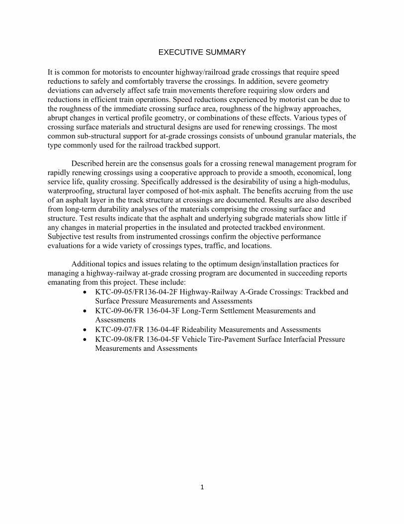
EXECUTIVE SUMMARY It is common for motorists to encounter highway/railroad grade crossings that require speed reductions to safely and comfortably traverse the crossings. In addition, severe geometry deviations can adversely affect safe train movements therefore requiring slow orders and reductions in efficient train operations. Speed reductions experienced by motorist can be due to the roughness of the immediate crossing surface area, roughness of the highway approaches, abrupt changes in vertical profile geometry, or combinations of these effects. Various types of crossing surface materials and structural designs are used for renewing crossings. The most common sub-structural support for at-grade crossings consists of unbound granular materials, the type commonly used for the railroad trackbed support.
Described herein are the consensus goals for a crossing renewal management program for rapidly renewing crossings using a cooperative approach to provide a smooth, economical, long service life, quality crossing. Specifically addressed is the desirability of using a high-modulus, waterproofing, structural layer composed of hot-mix asphalt. The benefits accruing from the use of an asphalt layer in the track structure at crossings are documented. Results are also described from long-term durability analyses of the materials comprising the crossing surface and structure. Test results indicate that the asphalt and underlying subgrade materials show little if any changes in material properties in the insulated and protected trackbed environment. Subjective test results from instrumented crossings confirm the objective performance evaluations for a wide variety of crossings types, traffic, and locations.
Additional topics and issues relating to the optimum design/installation practices for managing a highway-railway at-grade crossing program are documented in succeeding reports emanating from this project. These include:
KTC-09-05/FR136-04-2F Highway-Railway A-Grade Crossings: Trackbed and Surface Pressure Measurements and Assessments
KTC-09-06/FR 136-04-3F Long-Term Settlement Measurements and Assessments
KTC-09-07/FR 136-04-4F Rideability Measurements and Assessments KTC-09-08/FR 136-04-5F Vehicle Tire-Pavement Surface Interfacial Pressure
Measurements and Assessments
2
CHAPTER 1. AT-GRADE HIGHWAY-RAILWAY CROSSING MANAGEMENT
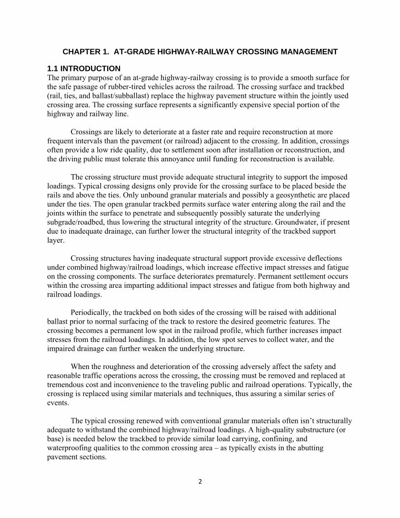
1.1 INTRODUCTION The primary purpose of an at-grade highway-railway crossing is to provide a smooth surface for the safe passage of rubber-tired vehicles across the railroad. The crossing surface and trackbed (rail, ties, and ballast/subballast) replace the highway pavement structure within the jointly used crossing area. The crossing surface represents a significantly expensive special portion of the highway and railway line. Crossings are likely to deteriorate at a faster rate and require reconstruction at more frequent intervals than the pavement (or railroad) adjacent to the crossing. In addition, crossings often provide a low ride quality, due to settlement soon after installation or reconstruction, and the driving public must tolerate this annoyance until funding for reconstruction is available. The crossing structure must provide adequate structural integrity to support the imposed loadings. Typical crossing designs only provide for the crossing surface to be placed beside the rails and above the ties. Only unbound granular materials and possibly a geosynthetic are placed under the ties. The open granular trackbed permits surface water entering along the rail and the joints within the surface to penetrate and subsequently possibly saturate the underlying subgrade/roadbed, thus lowering the structural integrity of the structure. Groundwater, if present due to inadequate drainage, can further lower the structural integrity of the trackbed support layer. Crossing structures having inadequate structural support provide excessive deflections under combined highway/railroad loadings, which increase effective impact stresses and fatigue on the crossing components. The surface deteriorates prematurely. Permanent settlement occurs within the crossing area imparting additional impact stresses and fatigue from both highway and railroad loadings. Periodically, the trackbed on both sides of the crossing will be raised with additional ballast prior to normal surfacing of the track to restore the desired geometric features. The crossing becomes a permanent low spot in the railroad profile, which further increases impact stresses from the railroad loadings. In addition, the low spot serves to collect water, and the impaired drainage can further weaken the underlying structure. When the roughness and deterioration of the crossing adversely affect the safety and reasonable traffic operations across the crossing, the crossing must be removed and replaced at tremendous cost and inconvenience to the traveling public and railroad operations. Typically, the crossing is replaced using similar materials and techniques, thus assuring a similar series of events. The typical crossing renewed with conventional granular materials often isn’t structurally adequate to withstand the combined highway/railroad loadings. A high-quality substructure (or base) is needed below the trackbed to provide similar load carrying, confining, and waterproofing qualities to the common crossing area – as typically exists in the abutting pavement sections.
3
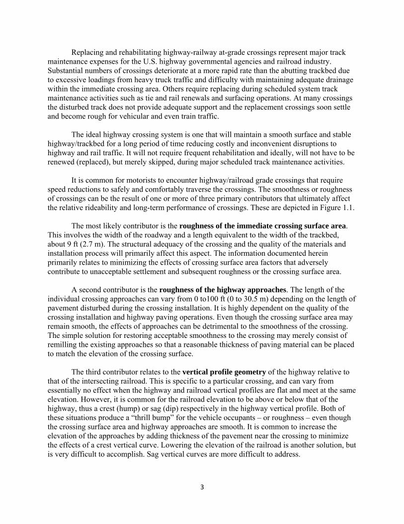
Replacing and rehabilitating highway-railway at-grade crossings represent major track maintenance expenses for the U.S. highway governmental agencies and railroad industry. Substantial numbers of crossings deteriorate at a more rapid rate than the abutting trackbed due to excessive loadings from heavy truck traffic and difficulty with maintaining adequate drainage within the immediate crossing area. Others require replacing during scheduled system track maintenance activities such as tie and rail renewals and surfacing operations. At many crossings the disturbed track does not provide adequate support and the replacement crossings soon settle and become rough for vehicular and even train traffic. The ideal highway crossing system is one that will maintain a smooth surface and stable highway/trackbed for a long period of time reducing costly and inconvenient disruptions to highway and rail traffic. It will not require frequent rehabilitation and ideally, will not have to be renewed (replaced), but merely skipped, during major scheduled track maintenance activities. It is common for motorists to encounter highway/railroad grade crossings that require speed reductions to safely and comfortably traverse the crossings. The smoothness or roughness of crossings can be the result of one or more of three primary contributors that ultimately affect the relative rideability and long-term performance of crossings. These are depicted in Figure 1.1. The most likely contributor is the roughness of the immediate crossing surface area. This involves the width of the roadway and a length equivalent to the width of the trackbed, about 9 ft (2.7 m). The structural adequacy of the crossing and the quality of the materials and installation process will primarily affect this aspect. The information documented herein primarily relates to minimizing the effects of crossing surface area factors that adversely contribute to unacceptable settlement and subsequent roughness or the crossing surface area. A second contributor is the roughness of the highway approaches. The length of the individual crossing approaches can vary from 0 to100 ft (0 to 30.5 m) depending on the length of pavement disturbed during the crossing installation. It is highly dependent on the quality of the crossing installation and highway paving operations. Even though the crossing surface area may remain smooth, the effects of approaches can be detrimental to the smoothness of the crossing. The simple solution for restoring acceptable smoothness to the crossing may merely consist of remilling the existing approaches so that a reasonable thickness of paving material can be placed to match the elevation of the crossing surface. The third contributor relates to the vertical profile geometry of the highway relative to that of the intersecting railroad. This is specific to a particular crossing, and can vary from essentially no effect when the highway and railroad vertical profiles are flat and meet at the same elevation. However, it is common for the railroad elevation to be above or below that of the highway, thus a crest (hump) or sag (dip) respectively in the highway vertical profile. Both of these situations produce a “thrill bump” for the vehicle occupants – or roughness – even though the crossing surface area and highway approaches are smooth. It is common to increase the elevation of the approaches by adding thickness of the pavement near the crossing to minimize the effects of a crest vertical curve. Lowering the elevation of the railroad is another solution, but is very difficult to accomplish. Sag vertical curves are more difficult to address.
4
Figure 1.1 Primary contributors affecting the relative rideability of crossings.
An additional situation that is difficult to address is when the highway is on a vertical grade and it intersects a railroad that is on a tangent, having no superelevation to match the vertical grade of the highway. This in effect creates a flat spot in the highway profile, inducing some measure of roughness, even though the crossing area may be very level and smooth. In situations where the railroad and highway intersect on horizontal curves, the individual superelevations may not match resulting in a warp in the highway vertical profile. This is also difficult to address unless the superelevation can be adjusted. It adversely affects the smoothness of the crossing even though the crossing surface area and highway approaches may be smooth. 1.2 DISCUSSION Deteriorating and rough crossing surfaces that have settled appreciably often result in undesirable driving conditions for both modes of transportation. Railroad and highway traffic volumes and axle loadings continue to increase so the frequency of encountering rough crossings will likely increase. The two modes require conflicting demands (Michigan, 2003). The railroad roadbed and track system is designed to be flexible, deflecting about 0.25 in. (6.5 mm) under normal railroad traffic. This support is normally carried through the crossing. The highway pavement structure is designed to be essentially rigid, deflecting a minuscule amount even under heavy trucks. The crossing (track) support is basically the track structure composed of granular (crushed aggregate or ballast) that may provide a different level of load-carrying capacity as that
5
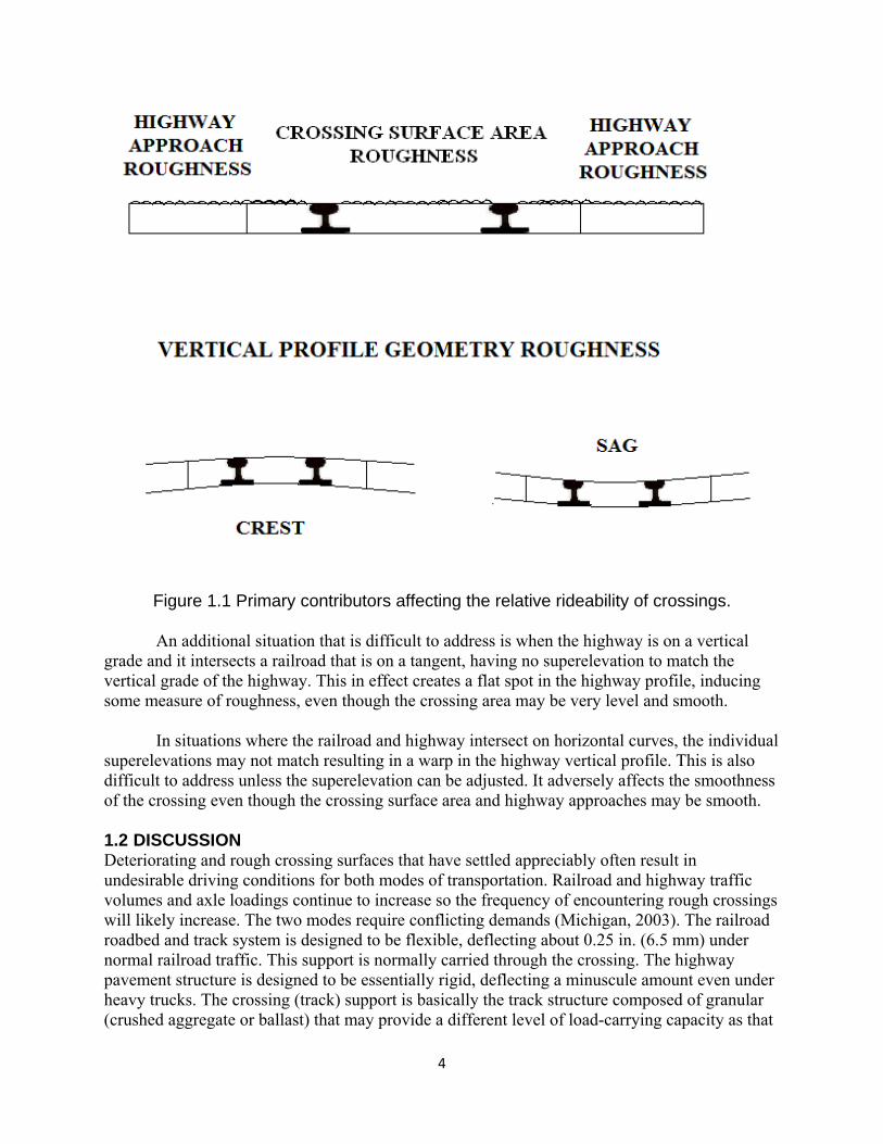
of the highway approaches. Thus the crossing area deflects excessively with subsequent permanent settlement. This results in rapid abrasion and wear of the crossing surface and support materials and the surface fails prematurely due to deterioration and settlement of the crossing. The most common track (sub-structural) support for highway-railway crossings consists of unbound granular materials as depicted in Figure 1.2. The upper portion is typically composed of open-graded, free-draining ballast size particles, generally sized from 3 in. (75 mm) to about 0.25 in. (6.5 mm). A granular layer, composed of finer sized particles, or subballast, is below the ballast. The voids in the ballast layer can potentially provide a path for water to seep through and permeate the underlying subballast and possibly the subgrade. This can decrease the structural integrity of the support. The inherent lack of support for the highway vehicles in the track crossing area can result in excessive deflections of the crossing. The excessive deflections, combined with the lessening of the support strength due to the high moisture contents of the support materials, ultimately result in permanent settlement of the crossing. This adversely affects the highway and railroad profiles in the immediate crossing area. The ideal sub-structural support system for a highway-railway crossing:
Provides adequate strength to resist the combined highway and rail loadings thus minimizing stresses on the underlying subgrade,
Minimizes vertical deflections and permanent deformations of the crossings due to highway and rail loadings so that the wear and deteriorations of the crossing components will be minimized, and
Serves to waterproof the underlying subgrade so that its load carrying capability will not be sacrificed even for marginal quality subgrades.
Long-term consolidation or settlement of the crossing should be minimal providing for a
smoother crossing with enhanced rideability characteristics for a longer period of time. The crossing will not have to be rehabilitated as frequently with attendant disruptions and expenses to the railroad company, governmental agency, and traveling public. 1.3 CONSENSUS GOALS FOR CROSSING RENEWAL PROCESS The goals for the ideal highway/rail crossing renewal process are to (Rose, Swiderski, and Anderson, 2009):
Provide a quality, safe, cost effective highway/rail crossing that will remain stable, smooth, and serviceable for both highway and rail traffic for a minimum of 15 years with minimal annual cost (minimizing costly disruptions for track and crossing maintenance),
Accomplish the complete renewal (trackbed and crossing surface) in a minimum of time without significant disruption to rail and highway traffic (maximum four-hour train curfew and 8 to 12-hour highway closure), and
Utilize a cooperative approach, involving both the railroad (and its contractor, if applicable) and the local governmental/highway agency, to provide an economical, quality product.
6
Figure 1.2 Cross-sectional views of all-granular and asphalt underlayment crossings.
The importance of a planning meeting well in advance of the anticipated date for the
renewal cannot be overemphasized. The railroad company and governmental/highway agency must address three primary issues (Walker, 2002):
Select Date – This can have a major effect on minimizing disruption and inconveniences to rail and highway traffic. High volume rail lines having regularly scheduled trains must be reviewed to minimize the adverse effects of track closures. Certain times on certain days may have lighter volumes and the railroad can adjust schedules slightly. The highway volume and type of traffic coupled with the availability of alternate routes and detours will be important concerns. Site specific factors must be considered.
Assign Responsibilities – These can be shared between the railroad company and governmental/highway agency to maximize the inherent expertise and economies of the two entities. The primary areas of responsibilities and the suggested responsibility party are:
Highway Closure and Traffic Control - Local highway/governmental agency
Public Announcements and Notification - Local highway/governmental agency
Obtain Railroad Curfew - Railroad company
Temporary Crossing Construction and Removal - Railroad company (or supervise)
7
Removal and Replacement of the Track and Crossing Surface - Railroad company (or its contractor)
Pave Asphalt Trenches and Approaches - Local highway/governmental agency (or supervise)
Share Cost – This may be predetermined as policies vary significantly due to specific governmental statutes and railroad company policies. However, a major objective is to extend available funds by assigning activities to the entity that can provide a quality product at the lowest cost. Normally, activities within the railroad right-of-way must be conducted by, or under supervision of, the railroad company. Typical shared costs are:
Removal and Installation of Track and Crossing Materials - Railroad company (may be reimbursed)
Traffic Control, Public Announcements, and Asphalt Paving - Local highway/governmental agency
8
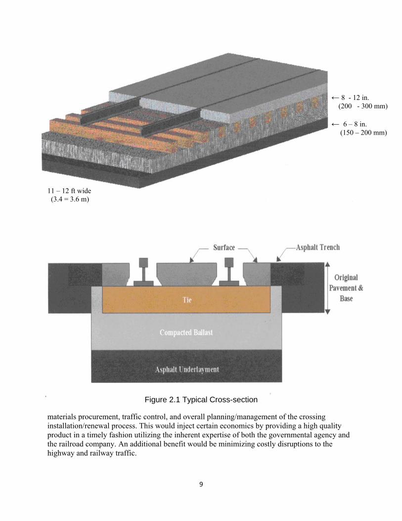
CHAPTER 2. COOPERATIVE FAST-TRACK CROSSING RENEWAL SYSTEM 2.1 BACKGROUND A deteriorating crossing offers unsafe and inefficient driving conditions for both modes of transportation. Crossings deteriorate quickly due to the conflicting demands each mode of transportation requires to adequately support the load it distributes. A train travels in a fixed, linear path distributing hundreds of tons on dime sized contact point. The base, roadbed, and track are designed to be flexible and permeable. However, a vehicle travels in a variety of directions with multiple turning movements and axle-weight combinations, having a roadbed and surface that is designed to be rigid and impermeable. When these two roadbeds intersect one another at a highway-railway crossing, the conflicting needs result in rapid wear on the crossing surface. The crossing, which is generally supported by the more flexible trackbed cannot bear the day-to-day highway traffic load and consequently fails prematurely (Swiderski, 2007). A typical unbound granular subballast layer supports most trackbeds at highway-railway grade crossings. This layer may allow water to seep through and permeate the underlying subgrade, resulting in decreased structural integrity of the trackbed. In addition to the inadequate support crossings provide, they are subjected to a dual loading from both the highway and railroad which increases the wear on crossing materials (Rose & Tucker, 2002). The inadequate support combined with increased moisture causes the crossing to fail and become low points in the highway and railroad profiles for both the highway and train traffic. The use of a layer of hot mix asphalt within the track substructure, in lieu of conventional granular subballast, is widely utilized to provide ideal properties to the crossing (Rose & Tucker, 2002). Literally thousands of crossings have been rehabilitated or initially constructed using this procedure. The basic process involves removing the old crossing surface and track panel followed by excavating the underlying mixture of ballast, subballast, and subgrade to the required depth. These are replaced with a compacted layer of hot mix asphalt (termed asphalt underlayment), a compacted layer of ballast, a new track panel, and a new crossing surface. Figure 2.1 contains a typical view of a rail/highway crossing containing an asphalt underlayment. 2.2 OBJECTIVES The primary objective of the research reported herein was to determine whether the enhanced support provided by the utilization of a layer of hot mix asphalt, in-lieu-of granular subballast, contributes to minimizing subsequent settlement while maintaining smooth crossing surfaces thereby extending the acceptable performance lives of crossings. An ancillary objective was to document the development of a “fast-track” approach, made possible with immediate enhanced structural support, to quickly stabilize the track during installation. This would virtually eliminate the need for “seasoning” the affected track by assuring minimal subsequent track settlement. The new crossing would be available for opening to train traffic soon after it was installed minimizing inconveniences to highway users and reducing train slow orders. An additional objective was to optimize and categorize a cooperative practice whereby the affected governmental (highway) agency and railroad company would jointly participate in
9
← 8 - 12 in. (200 - 300 mm) ← 6 – 8 in. (150 – 200 mm) 11 – 12 ft wide (3.4 = 3.6 m)
Figure 2.1 Typical Cross-section
materials procurement, traffic control, and overall planning/management of the crossing installation/renewal process. This would inject certain economics by providing a high quality product in a timely fashion utilizing the inherent expertise of both the governmental agency and the railroad company. An additional benefit would be minimizing costly disruptions to the highway and railway traffic.
10
CHAPTER 3. ASPHALT UNDERLAYMENT TRACKBED CROSSINGS
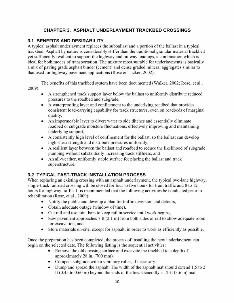
3.1 BENEFITS AND DESIRABILITY A typical asphalt underlayment replaces the subballast and a portion of the ballast in a typical trackbed. Asphalt by nature is considerably stiffer than the traditional granular material trackbed yet sufficiently resilient to support the highway and railway loadings, a combination which is ideal for both modes of transportation. The mixture most suitable for underlayments is basically a mix of paving grade asphalt binder (cement) and dense graded mineral aggregates similar to that used for highway pavement applications (Rose & Tucker, 2002). The benefits of this trackbed system have been documented (Walker, 2002; Rose, et al., 2009):
A strengthened track support layer below the ballast to uniformly distribute reduced pressures to the roadbed and subgrade,
A waterproofing layer and confinement to the underlying roadbed that provides consistent load-carrying capability for track structures, even on roadbeds of marginal quality,
An impermeable layer to divert water to side ditches and essentially eliminate roadbed or subgrade moisture fluctuations, effectively improving and maintaining underlying support,
A consistently high level of confinement for the ballast, so the ballast can develop high shear strength and distribute pressures uniformly,
A resilient layer between the ballast and roadbed to reduce the likelihood of subgrade pumping without substantially increasing track stiffness, and
An all-weather, uniformly stable surface for placing the ballast and track superstructure.
3.2 TYPICAL FAST-TRACK INSTALLATION PROCESS When replacing an existing crossing with an asphalt underlayment, the typical two-lane highway, single-track railroad crossing will be closed for four to five hours for train traffic and 8 to 12 hours for highway traffic. It is recommended that the following activities be conducted prior to rehabilitation (Rose, et al., 2009):
Notify the public and develop a plan for traffic diversion and detours, Obtain adequate outage (window of time), Cut rail and use joint bars to keep rail in service until work begins, Saw pavement approaches 7 ft (2.1 m) from both sides of rail to allow adequate room
for excavation, and Store materials on-site, except for asphalt, in order to work as efficiently as possible.
Once the preparation has been completed, the process of installing the new underlayment can begin on the selected date. The following listing is the sequential activities:
Remove the old crossing surface and excavate the trackbed to a depth of approximately 28 in. (700 mm).
Compact subgrade with a vibratory roller, if necessary. Dump and spread the asphalt. The width of the asphalt mat should extend 1.5 to 2
ft (0.45 to 0.60 m) beyond the ends of the ties. Generally a 12-ft (3.6 m) mat
11
width is used. A minimum length of 25 to 100 ft (7.6 to 30.5 m) is recommended beyond the ends of the crossing to provide a transition zone. The asphalt mat is typically 6 in. (150 mm) thick.
Compact the asphalt. A compaction level of 95% is preferred using a steel wheeled, vibratory type standard roller. It is also beneficial to leave a side slope allowing for drainage along the asphalt.
Dump and spread the ballast. A thickness of 8 to 12 in. (200 to 300 mm) of ballast should be on top of the asphalt after compaction.
Compact the ballast to stabilize the trackbed and minimize subsequent settlement. Position the prefabricated track panel on the compacted ballast. Bolt the new rail to the existing rail, welds can be made later. Add the cribbing ballast and additional ballast to fill in the cribs and allow for a
track raise and adjustment. Surface, tamp, and broom the immediate crossing area. Install the crossing surface including the trenches along the track. Pave the highway approaches.
Normally these activities will be shared between the local highway agency and the railroad company. Planning should begin several weeks in advance of the actual work.
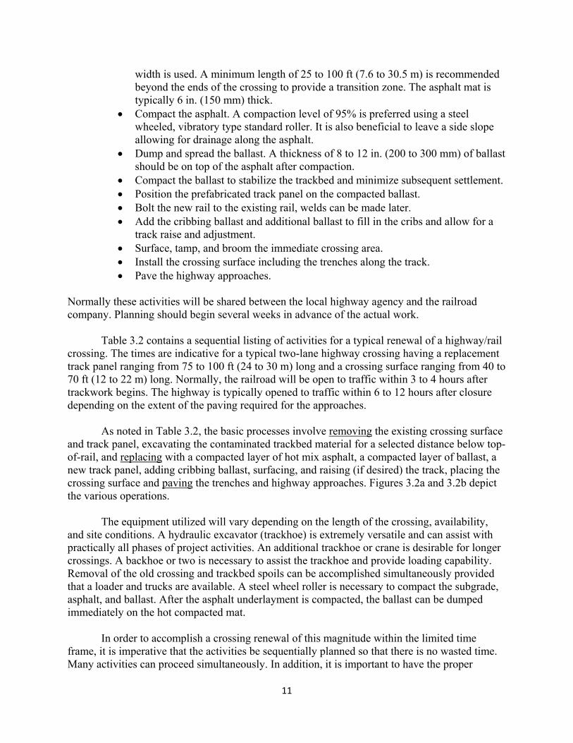
Table 3.2 contains a sequential listing of activities for a typical renewal of a highway/rail crossing. The times are indicative for a typical two-lane highway crossing having a replacement track panel ranging from 75 to 100 ft (24 to 30 m) long and a crossing surface ranging from 40 to 70 ft (12 to 22 m) long. Normally, the railroad will be open to traffic within 3 to 4 hours after trackwork begins. The highway is typically opened to traffic within 6 to 12 hours after closure depending on the extent of the paving required for the approaches.
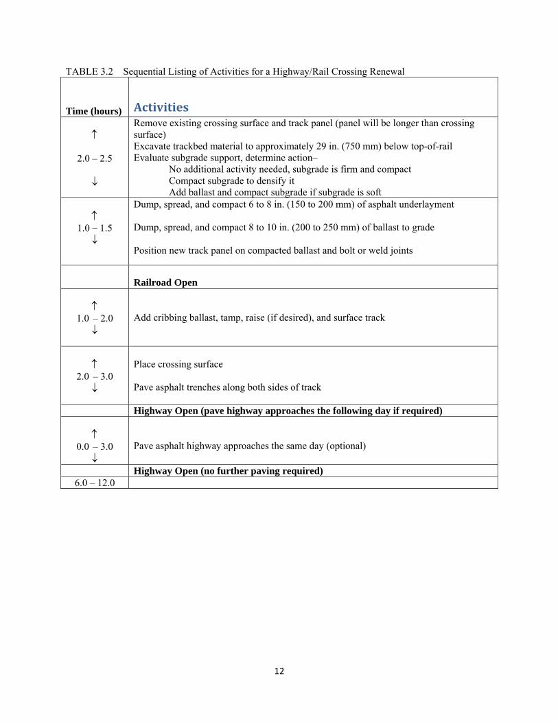
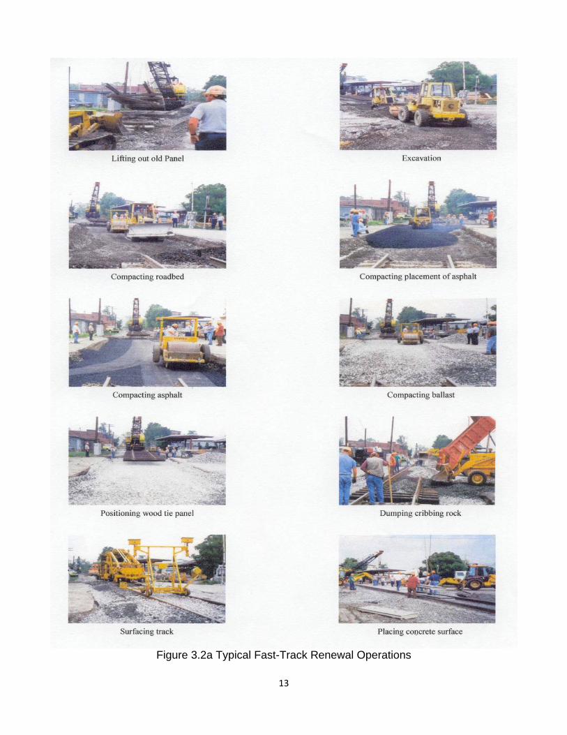
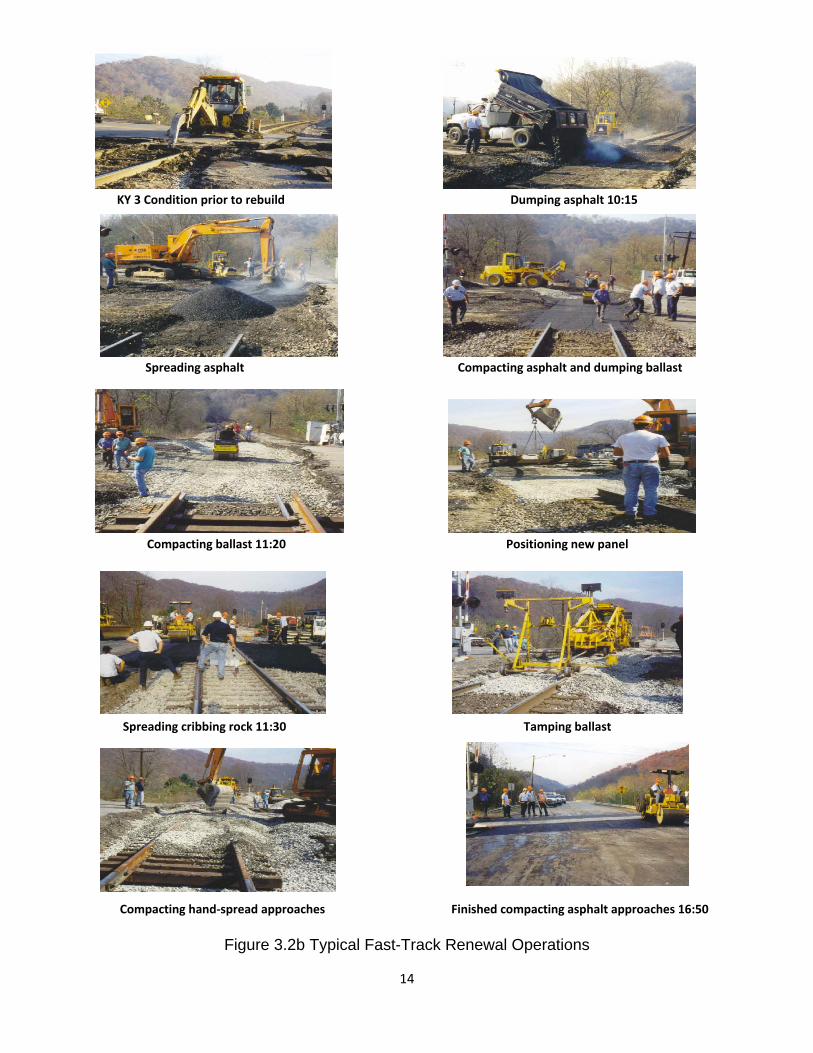
As noted in Table 3.2, the basic processes involve removing the existing crossing surface and track panel, excavating the contaminated trackbed material for a selected distance below top-of-rail, and replacing with a compacted layer of hot mix asphalt, a compacted layer of ballast, a new track panel, adding cribbing ballast, surfacing, and raising (if desired) the track, placing the crossing surface and paving the trenches and highway approaches. Figures 3.2a and 3.2b depict the various operations. The equipment utilized will vary depending on the length of the crossing, availability, and site conditions. A hydraulic excavator (trackhoe) is extremely versatile and can assist with practically all phases of project activities. An additional trackhoe or crane is desirable for longer crossings. A backhoe or two is necessary to assist the trackhoe and provide loading capability. Removal of the old crossing and trackbed spoils can be accomplished simultaneously provided that a loader and trucks are available. A steel wheel roller is necessary to compact the subgrade, asphalt, and ballast. After the asphalt underlayment is compacted, the ballast can be dumped immediately on the hot compacted mat. In order to accomplish a crossing renewal of this magnitude within the limited time frame, it is imperative that the activities be sequentially planned so that there is no wasted time. Many activities can proceed simultaneously. In addition, it is important to have the proper
12
TABLE 3.2 Sequential Listing of Activities for a Highway/Rail Crossing Renewal
Time (hours) Activities
2.0 – 2.5
Remove existing crossing surface and track panel (panel will be longer than crossing surface) Excavate trackbed material to approximately 29 in. (750 mm) below top-of-rail Evaluate subgrade support, determine action– No additional activity needed, subgrade is firm and compact Compact subgrade to densify it Add ballast and compact subgrade if subgrade is soft
1.0 – 1.5
Dump, spread, and compact 6 to 8 in. (150 to 200 mm) of asphalt underlayment Dump, spread, and compact 8 to 10 in. (200 to 250 mm) of ballast to grade Position new track panel on compacted ballast and bolt or weld joints
Railroad Open
1.0 – 2.0
Add cribbing ballast, tamp, raise (if desired), and surface track
2.0 – 3.0
Place crossing surface Pave asphalt trenches along both sides of track
Highway Open (pave highway approaches the following day if required)
0.0 – 3.0
Pave asphalt highway approaches the same day (optional)
Highway Open (no further paving required) 6.0 – 12.0
13
Figure 3.2a Typical Fast-Track Renewal Operations
14
KY 3 Condition prior to rebuild Dumping asphalt 10:15
Spreading asphalt Compacting asphalt and dumping ballast
Compacting ballast 11:20 Positioning new panel
Spreading cribbing rock 11:30 Tamping ballast
Compacting hand‐spread approaches Finished compacting asphalt approaches 16:50
Figure 3.2b Typical Fast-Track Renewal Operations
15
equipment adequately sized to provide the production rates necessary to complete the work in the allotted time. Most of the labor is involved with assembling the track and crossing surface. Various types of crossing surfaces have been installed. These include: full width pre-cast concrete, partial width pre-cast concrete, full-depth rubber, rubber seal and asphalt, rubber header and asphalt, full width asphalt, full width timer and experimental composite surfaces. The relative ease of the installation of the surface impacts the project time schedule.
3.3 INSTALLATION TIME One of the most attractive characteristics of using an asphalt underlayment with this method of crossing rehabilitation is the fact that the entire crossing replacement can be accomplished in one day with typical closures of 3 to 4 hours for the railroad and 6 to 12 hours for the highway. For a light traffic rail line or a multiple track line, closures may not impact train operations significantly. However, on single-track rail lines with heavy train traffic, the amount of time needed to accomplish the work can dictate if and when rehabilitation work will be scheduled. Also, closing the crossing for only one day minimizes disruption to the traveling public. Overall, this method provides a quality, smooth crossing in a minimal amount of time. Appendix A contains detailed descriptions of the various activities typically involved with the renewal/rehabilitation of at-grade highway-railway crossings using the cooperative fast-track approach incorporating a layer of hot-mix asphalt (underlayment) in the track structure. 3.4 COST AND ECONOMICS In addition to time, cost is another major factor in determining the extent of the work to be performed. Asphalt underlayments have been extensively used in crossings since the early 1980s. Thousands of these supporting mats have been placed in service over the past 25 plus years. Many of these crossings are heavy-duty crossings that are still in service or maybe only surfaced through once in order to change out the crossing surface. A service life of this magnitude for crossings is very desirable. If the benefits are such, it may be justification for the extra expense of a layered installation system utilizing asphalt underlayment when renewing a crossing. Furthermore, the extra costs of the asphalt underlayment are typically not very significant. The cost of obtaining and placing the asphalt underlayment will vary at each jobsite. Factors that affect this cost are:
Separate placement crew and paving machine will increase costs compared to merely back dumping the mix, spreading it, and compacting it with on-site equipment,
Prevailing cost of asphalt mix in the local area, Length (time) of haul to site, Size (tonnage) of the project, Availability and cooperation of local contractors, and Ease of delivery access and construction maneuverability.
Typically, the in-place cost of an asphalt underlayment that is back-dumped will range
from $20 to $30 per track foot ($66 to $98 per track meter). Crossing track panel lengths range from 60 to 100 feet (18 to 30 m) for a two-lane highway, so the total cost for the in-place asphalt underlayment range from $1,200 to $3,000. The extra cost for the asphalt is further reduced from
16
this figure when the cost of the sub-ballast or geotextile fabric (if considered) that it replaces is factored in. The total rehabilitation costs for a major crossing typically ranges from $20,000 to $40,000. The total net increase in cost of the renewal process using asphalt underlayment is approximately 5% to 10%, which is minimal compared to the benefits that it provides. A practice to reduce cost to the railroad company while still obtaining a quality rehabilitated crossing with an asphalt underlayment and panelized system is to share the renewal costs among two or more parties. The local highway/governmental agency is better positioned and experienced to provide certain activities more economically than is the railroad company. These activities include asphalt paving, traffic control, and public announcements. Kentucky has been one of the initial states involved in utilizing a cooperative approach. In many of the crossing renewal projects, the state or county highway department has been willing to offset some of the expense to the railroad company by providing the activities listed above, and paying for items such as the asphalt and/or surface materials. By sharing the cost of the renewal projects, the funds for renewal projects are extended. Extended funds mean that more crossings can be renewed by the railroad company for a set budget making for a smoother drive over more railroad crossings.
17
CHAPTER 4. TRACKBED MATERIALS DURABILITY TESTS 4.1 BACKGROUND A characterization and evaluation study was conducted to ascertain the effects of long-term exposure in various trackbed environments on the material properties of the trackbed materials – specifically asphalt layer and underlying (roadbed) subgrade. The primary purpose of the testing program was to determine if any weathering degradation or physical/chemical deterioration of the materials were occurring that could adversely affect long-term performance of the trackbeds. Seven asphalt trackbeds, ranging in age from 12 to 25 years; on heavy traffic revenue lines in four states were core drilled. Test data on the trackbed materials were compared to data obtained previously. The expected benefits and trackbed life projections are discussed relative to current basic design and construction practices. 4.2 ASPHALT TRACKBED MATERIALS TESTS AND EVALUATIONS Seven asphalt trackbeds, located in four different states, ranging from 12 to 25 years old and having various asphalt thicknesses and trackbed support materials, were selected for materials characterization studies. Samples were obtained during summer 2007 and the detailed results were reported in 2008 (Rose & Lees, 2008). Previous characterization studies, primarily conducted in 1998 (Rose, et al., 2000) (Rose, 1998), were available for selected projects and evaluated for comparison purposes. Core samples were taken at three randomly selected locations for each trackbed evaluated. After removing the ballast, the asphalt layer was core drilled from the field side crib area next to the rail (Figure 4.2). The 6 in. (150 mm) diameter asphalt cores were extracted and the core drilling water was immediately removed so that it would not contaminate the underlying subgrade. The conditions of the cores were observed, measurements were taken, and the cores were sealed in plastic bags for transportation to the testing laboratory. The subgrade underlying the asphalt was removed with an auger for a 12 in. (300 mm) depth below the asphalt. The soil was sealed in plastic bags for immediate transportation to the testing laboratory. Detailed information and descriptions of the tests and evaluations are contained in the 2008 AREMA Conference Proceedings (Rose & Lees, 2008). Summary information follows. 4.2.1 Geotechnical Tests and Evaluations The in-situ (prevailing) moisture contents of the subgrade samples were determined for comparisons with subsequent analyses. In addition, typical grain size analyses and Atterberg limits tests were conducted in order to classify the subgrade materials. Standard Proctor moisture-density relationships were established and California bearing ratio tests were conducted on the materials prepared at their respective optimum moisture contents and tested in the unsoaked condition immediately and in the soaked conditions after 96 hours. 4.2.1.1 In-situ moisture contents There was significant interest in determining the prevailing moisture contents for the subgrade materials directly under the asphalt layer and comparing these with the previous 1998 in-situ measurements and with the optimum moisture contents for the respective materials. Every effort was made to remove core drilling water, this protecting the integrity of the subgrade samples. No
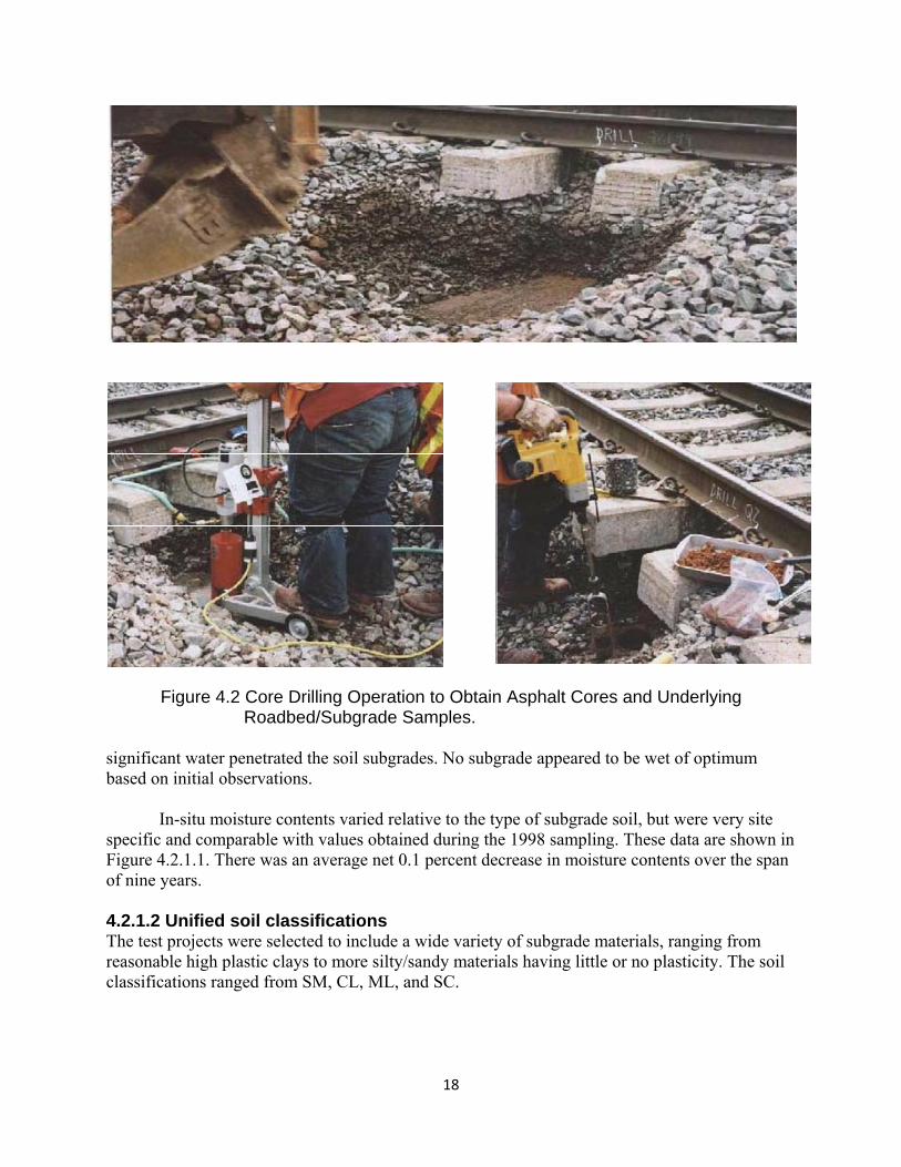
18
Figure 4.2 Core Drilling Operation to Obtain Asphalt Cores and Underlying Roadbed/Subgrade Samples. significant water penetrated the soil subgrades. No subgrade appeared to be wet of optimum based on initial observations. In-situ moisture contents varied relative to the type of subgrade soil, but were very site specific and comparable with values obtained during the 1998 sampling. These data are shown in Figure 4.2.1.1. There was an average net 0.1 percent decrease in moisture contents over the span of nine years. 4.2.1.2 Unified soil classifications The test projects were selected to include a wide variety of subgrade materials, ranging from reasonable high plastic clays to more silty/sandy materials having little or no plasticity. The soil classifications ranged from SM, CL, ML, and SC.
19
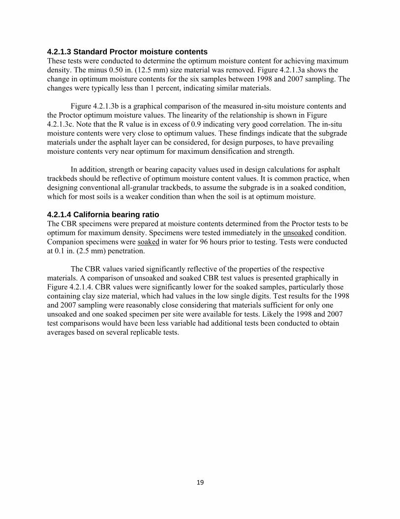
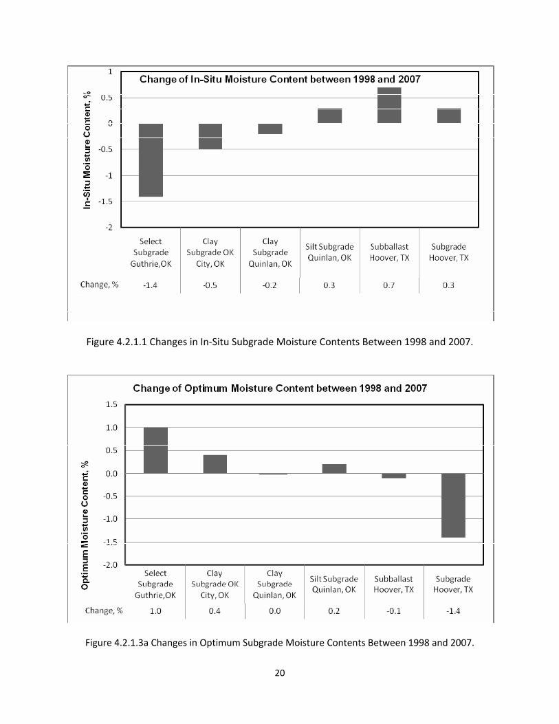
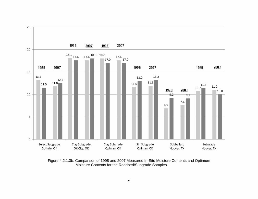
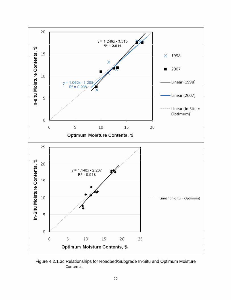
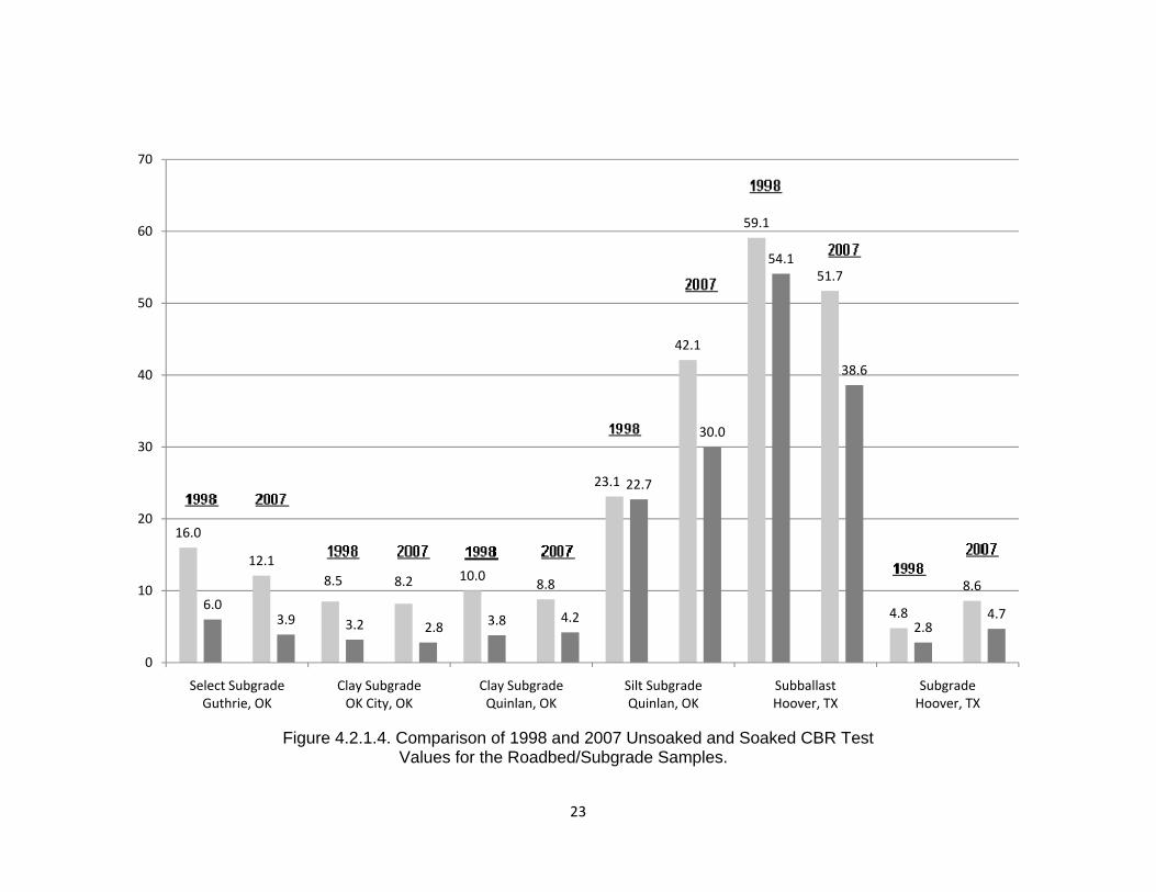
4.2.1.3 Standard Proctor moisture contents These tests were conducted to determine the optimum moisture content for achieving maximum density. The minus 0.50 in. (12.5 mm) size material was removed. Figure 4.2.1.3a shows the change in optimum moisture contents for the six samples between 1998 and 2007 sampling. The changes were typically less than 1 percent, indicating similar materials. Figure 4.2.1.3b is a graphical comparison of the measured in-situ moisture contents and the Proctor optimum moisture values. The linearity of the relationship is shown in Figure 4.2.1.3c. Note that the R value is in excess of 0.9 indicating very good correlation. The in-situ moisture contents were very close to optimum values. These findings indicate that the subgrade materials under the asphalt layer can be considered, for design purposes, to have prevailing moisture contents very near optimum for maximum densification and strength. In addition, strength or bearing capacity values used in design calculations for asphalt trackbeds should be reflective of optimum moisture content values. It is common practice, when designing conventional all-granular trackbeds, to assume the subgrade is in a soaked condition, which for most soils is a weaker condition than when the soil is at optimum moisture. 4.2.1.4 California bearing ratio The CBR specimens were prepared at moisture contents determined from the Proctor tests to be optimum for maximum density. Specimens were tested immediately in the unsoaked condition. Companion specimens were soaked in water for 96 hours prior to testing. Tests were conducted at 0.1 in. (2.5 mm) penetration. The CBR values varied significantly reflective of the properties of the respective materials. A comparison of unsoaked and soaked CBR test values is presented graphically in Figure 4.2.1.4. CBR values were significantly lower for the soaked samples, particularly those containing clay size material, which had values in the low single digits. Test results for the 1998 and 2007 sampling were reasonably close considering that materials sufficient for only one unsoaked and one soaked specimen per site were available for tests. Likely the 1998 and 2007 test comparisons would have been less variable had additional tests been conducted to obtain averages based on several replicable tests.
20
Figure 4.2.1.1 Changes in In‐Situ Subgrade Moisture Contents Between 1998 and 2007.
Figure 4.2.1.3a Changes in Optimum Subgrade Moisture Contents Between 1998 and 2007.
21
Figure 4.2.1.3b. Comparison of 1998 and 2007 Measured In-Situ Moisture Contents and Optimum Moisture Contents for the Roadbed/Subgrade Samples.
13.2
18.1 18.0
11.6
6.9
10.711.5
17.617.0
13.0
9.2
11.411.8
17.6 17.6
11.9
7.6
11.0
12.5
18.0
17.0
13.2
9.110.0
0
5
10
15
20
25
Select Subgrade Guthrie, OK
Clay Subgrade OK City, OK
Clay Subgrade Quinlan, OK
Silt Subgrade Quinlan, OK
Subballast Hoover, TX
Subgrade Hoover, TX
22
Figure 4.2.1.3c Relationships for Roadbed/Subgrade In-Situ and Optimum Moisture Contents.
23
Figure 4.2.1.4. Comparison of 1998 and 2007 Unsoaked and Soaked CBR Test
Values for the Roadbed/Subgrade Samples.
16.0
8.5 10.0
23.1
59.1
4.86.0
3.2 3.8
22.7
54.1
2.8
12.1
8.2 8.8
42.1
51.7
8.6
3.92.8
4.2
30.0
38.6
4.7
0
10
20
30
40
50
60
70
Select Subgrade Guthrie, OK
Clay Subgrade OK City, OK
Clay Subgrade Quinlan, OK
Silt Subgrade Quinlan, OK
Subballast Hoover, TX
Subgrade Hoover, TX
24
As noted previously, the in-situ moisture contents for individual samples were very close to those determined from the Proctor test to be near optimum. This relationship is shown graphically in Figure 4.2.1.3c. Since the unsoaked CBR values are derived from tests on samples at optimum moisture contents, and the test results from samples under asphalt trackbeds were determined to be at or very near optimum moisture contents, it is obvious that the unsoaked CBR bearing capacity values are appropriate to use for structural design calculations. The soaked (lower) CBR values result in a conservative overdesign. The preceding statements are not necessarily applicable to the open all-granular trackbeds, which are prone to variable moisture contents depending on the amount of rainfall and surface drainage conditions, and corresponding variations in support strength. The subgrade/roadbed materials underlying the asphalt layers were at moisture contents near optimum, and based on long-term monitoring at two sites, maintain optimum moisture conditions for indefinite periods. 4.2.2 Asphalt Mixture Tests and Evaluations The asphalt cores were subjected to density, voids analysis and resilient modulus tests. Subsequently the asphalt binder was extracted, using trichloroethylene, in order to determine the asphalt binder contents and extracted aggregate gradations. The extracted binder was subsequently recovered from the solvent for penetration, viscosity, and dynamic shear rheometer tests. 4.2.2.1 Mix extraction tests and core analyses The extraction test results were indicative of dense-graded base mixes with 1.0 in. (25 mm) maximum size aggregate and about 6 percent of the aggregate passing the No. 200 sieve. These are basically in conformance with guidelines previously described (Rose, 2006) (Rose, 1998). Asphalt binder contents varied somewhat, ranging from 4.5 to 7.0 percent. No particular changes were evident in aggregate gradations or asphalt binder contents over the period of years. Tests on the asphalt cores included density and voids analyses and resilient modulus tests. The air voids were typically higher than desirable for five of the sites ranging from 5 to 9 percent. The air voids were purposefully maintained at 2 to 3 percent range at three of the sites. This low range is considered to be optimum to resist premature oxidation of the binder. Average air voids for each site were less than the 8 percent maximum normally believed to represent the upper limit to provide an impermeable layer. The industry standard resilient modulus test was used to measure the modulus of elasticity of the asphalt cores. Repeated loads were applied to a cylindrical specimen and the displacements were measured. The values were measured under indirect tensile loading for the resilient modulus. Tests were conducted at two standard temperatures which represent the nominal lowest, 5°C (41°F) and highest, 25°C (77°F), temperature asphalt experiences in the insulated trackbed environment. Values were typically several orders of magnitude higher at the lower temperature, which is normal for a viscoelastic, thermoplastic material – and is characteristic of the asphalt binder in the mix. At lower temperatures, the asphalt becomes stiffer, as reflected in higher modulus (or stiffness) values. At higher temperatures, the asphalt becomes less stiff. Obviously, for asphalt highway environments, where the asphalt is exposed to greater temperature extremes, the
25
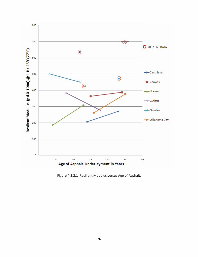
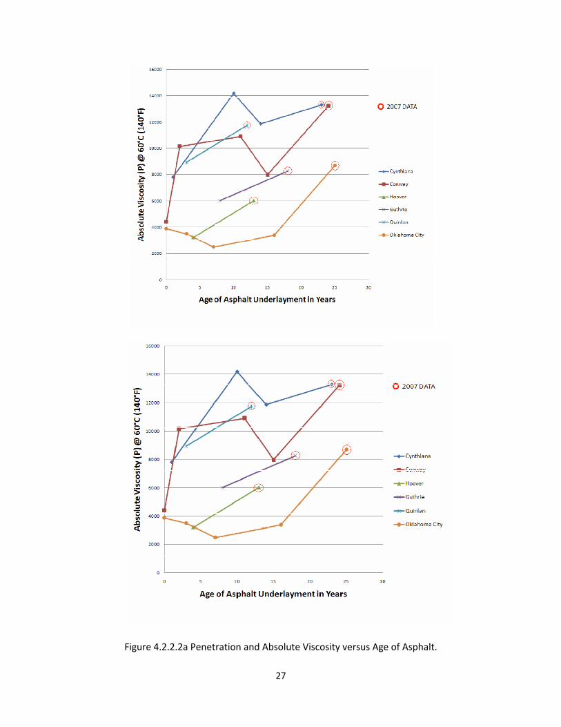
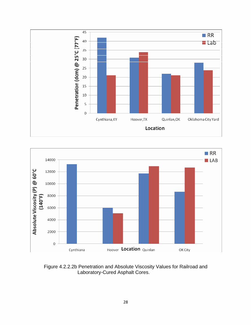
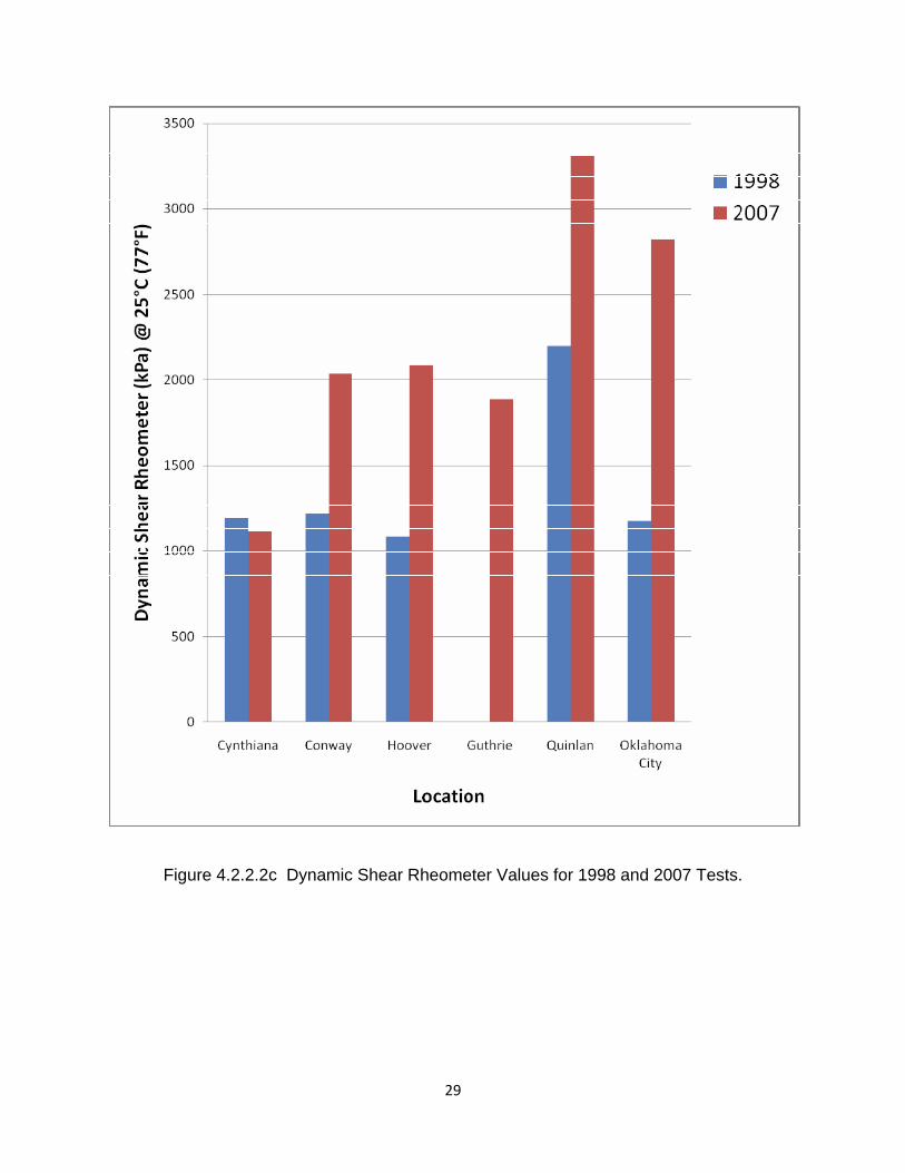
stiffness differences from winter to summer are significantly greater than those existing in the insulated trackbed environment. Figure 4.2.2.1 is a plot of Resilient Modulus versus Age for the asphalt mixes. The “circled” symbols represent data for cores (obtained from the trackbed in 1998) that cured the final nine years in the laboratory environment. They are plotted directly above the railroad cured data for similar ages. Note that the modulus values for the cores cured the last nine years in the laboratory were higher than the cores in the railroad environment. The measured modulus values are reasonably consistent for the various sites. There is no particular trend or changes in modulus as a function of time. The mixes vary in asphalt contents, densities, aggregate gradations, and binder properties from site-to-site, which can be expected to produce variations in modulus values. However, these variations are minimal. The significant factor is that the values are reasonably typical for new, unweathered mixes not exemplifying fatigue and cracking – thus low values, or exemplifying hardening/weathering of the binder – thus high values. The values are basically intermediate in magnitude, even after many years of loading and weathering in the trackbed. The asphalt appears to be undergoing little, if any, weathering or deterioration in the trackbed environment. 4.2.2.2 Recovered asphalt binder tests Tests for Penetration, Absolute and Kinematic Viscosities, and Dynamic Shear Rheometer were conducted on the recovered asphalt binders. Plots of Penetration and Absolute Viscosity versus Age of the Asphalt Underlayments are contained in Figure 4.2.2.2a. The data points circled at the ends of the trend lines represent the 2007 values. The preceding data points are for test values nine years prior, or 1998 values. Penetration values will tend to decrease and viscosity values will tend to increase with time due to expected oxidizing and hardening of the asphalt binders. There is indication of this phenomenon when comparing the 1998 and 2007 test values. However, the Abson method (ASTM D1856) was used for the 1998 and prior asphalt recoveries; whereas, the Rotary Evaporator method (ASTM D5404) was used for the 2007 recoveries. The Rotovapor method is considered more effective at removing the solvent. Therefore, the 2007 penetration values would be expected to be lower and the 2007 absolute viscosity values would be expected to be higher than their respective 1998 values. These trends are evident from Figure 4.2.2.2b. It is likely that the original asphalt binders were PAC 60-70 penetration or AC-20 viscosity graded. The effects of short-term aging (elevated temperatures) during the pavement construction process and long-term aging for several years will reduce the binder penetration to the 25 to 40 range and the absolute viscosity at 60°C (140°F) will be maintained to less than 15,000 poises (ASTM, 2007). These samples meet these criteria, indicating minimal oxidation and weathering. The Dynamic Shear Rheometer (DSR) procedure for evaluating asphalt binders was developed in the mid-1990s. Fortunately this test was conducted in 1998 on samples from 5 of the 6 sites and this data is compared to the 2007 data in Figure 4.2.2.2c. The standard for performance grade asphalt binders, after short- and long-term aging, is that the DSR at 25°C
26
Figure 4.2.2.1 Resilient Modulus versus Age of Asphalt.
27
Figure 4.2.2.2a Penetration and Absolute Viscosity versus Age of Asphalt.
28
Figure 4.2.2.2b Penetration and Absolute Viscosity Values for Railroad and Laboratory-Cured Asphalt Cores.
29
Figure 4.2.2.2c Dynamic Shear Rheometer Values for 1998 and 2007 Tests.
30
(77°F) should be less than 5,000 kPa. Note in Figure 4.2.2.2c that all of the samples are well below 5,000 kPa, another indication that the asphalt binders in the trackbed cores are not oxidizing and hardening excessively (ASTM, 2007). 4.2.2.3 Discussion It is not surprising that the asphalt binders in the trackbed cores are not oxidizing and hardening to the extent normally observed for asphalt highway pavements. This is largely due to two factors. The surface of the asphalt is typically submerged 20 in. (500 mm) from the surface (atmosphere) by the ballast/tie cribs and the depth of ballast below the ties. The lack of sunlight and reduced oxygen largely negates normal weathering which occurs in highway pavements exposed to sunlight. Secondly, the range temperature extremes which the HMA mat undergoes from summer to winter is significantly less in the insulated trackbed environment than for exposed highway pavements. This information was developed initially during 1982 and 1995 tests in Kentucky from buried thermistors, and reported previously (Rose, et al., 2000). Additional tests during 2000 at the AAR Pueblo test site confirmed the previous tests (Li, et al., 2001). 4.3 SUMMARY AND CONCLUSIONS The primary purpose of this investigation was to determine, based on test results, current materials properties of the asphalt and underlying materials in order to assess if any weathering or deterioration of the materials was occurring in the trackbed environment which could adversely affect long-term performance of asphalt underlayment trackbeds.
Material characterization evaluations were conducted on asphalt cores and subgrade/roadbed samples from seven asphalt trackbeds. The trackbeds were from 12 to 25 years old when tested and were distributed over four states. The inherent conditions varied significantly from site-to-site. These include asphalt thickness and composition, ballast thickness, trackbed support, and traffic. Previous characterization evaluations were available for the projects and the results were included for comparisons with recent evaluations. The significant finding relative to the materials (old roadbed/subgrade) directly under the asphalt layer, is that the in-situ moisture contents are very close to laboratory determined optimum values for maximum density of the respective materials. The asphalt layer is not performing as a membrane to collect and trap moisture, thus weakening support. Actually, since the in-situ moisture contents are at or near optimum for maximum density, the strengths and load carrying capacities of the underlying materials are also at or near optimum. Furthermore, average moisture contents remain essentially unchanged, at or near optimum, for the two projects from which previous data was available. For design purposes, it is reasonable to base strength or bearing capacity values at optimum conditions (moisture content and density) for the material under the asphalt layer. Using strength or bearing capacity values determined for the soaked condition, common for highway designs, is inappropriate for asphalt trackbed designs. The unsoaked, optimum moisture content condition is consistent with in-service trackbed conditions.
An equally significant finding, relative to the asphalt cores characterizations, is that the asphalt binders and asphalt mixes do not exhibit any indication of excessive hardening
31
(brittleness), weathering, or deterioration even after many years in the trackbed environment. This is considered to be primarily due to the insulative effects of the overlying ballast which protects the asphalt from excessive temperature extremes and oxidation and hardening of the asphalt binder. These factors will contribute to a long fatigue life for the asphalt layer. There is no indication that the asphalt layers are experiencing any loss of fatigue life based on resilient modulus test on the extracted cores.
The typical failure modes experienced by asphalt highway pavements are 1) rutting at
high temperatures, 2) cracking and fatigue at low temperatures, 3) stripping/raveling under the suction of high tire pressures on wet pavements, and 4) progressive fatigue cracking due to inadequate subgrade support, generally augmented by high moisture and improper drainage. These conditions do not exist in asphalt railroad trackbeds. For example, the temperatures are not sufficiently high to promote rutting. Conversely, the temperatures are not sufficiently low to promote low temperature cracking and decreased fatigue life, nor does the asphalt binder weather or harden excessively in the insulated trackbed environment which would have further negative influence on cracking and fatigue life. Obviously the tendency to strip/ravel is essentially eliminated in the trackbed environment since there is no rubber suction action. Also, the moisture contents of the underlying subgrade/roadbed support materials are maintained at or near optimum for maximum density and support strength.
In addition, peak dynamic vertical pressures on top of the asphalt layer are typically less
than the 20 psi (138 kPa) under 286,000 lb (130 metric ton) locomotives and heavily loaded cars (Rose, 2008). This is only two to three times larger than the pressure exerted by an average-size person standing on an asphalt pavement, and much less than pressures exerted by heavily loaded highway trucks, which can be in excess of 100 psi (690 kPa). These peak dynamic pressures are further reduced to less than 10 psi (69 kPa) under the asphalt layer at the subgrade interface (Li, et al., 2001).
Based on the findings and analyses of the research reported herein, asphalt underlayments installed in conformance with the basic design and construction practices also reported herein, should have an extremely long service life as a premium subballast to properly support railroad tracks. There is no indication of any deterioration or cracks of the asphalt after many years of heavy traffic under widely varying conditions. Ancillary benefits of a long-lasting premium subballast support material for railroad tracks include the following: increased strength, decreased abrasion, and increased life of the ballast; decreased wear and improved fatigue life of the ties, rail, and premium-cost track components such as special trackworks; a consistent level of track stiffness (modulus) designed for optimum levels; reduced maintenance activities and associated track closures; and improved adherence to track geometric parameters. All of these benefits impact favorably on achieving efficient operation of the rail transportation system.
32
CHAPTER 5. DESCRIPTIONS FOR REPRESENTATIVE PROJECTS
5.1 DISCUSSION Appendix A contains Detailed Descriptions of the Various Activities involved with the renewal/rehabilitation of highway-railway at-grade crossings using the cooperative fast-track approach incorporating a layer of hot-mix asphalt (underlayment) within the track structure. Individual crossings will exhibit situations unique to the particular site, so preliminary evaluations of the conditions should be conducted during the planning stage. For example, drainage issues are unique for each site. Both sub-surface and surface drainages conditions must be evaluated. The discussion in Appendix A relates to the ideal situations. Some modifications will be necessary based on engineering judgment and analyses. 5.2 SUMMARY LISTINGS Appendixes B, C, D, and E contain Descriptions for Several Representative Projects. The individual projects were selected as being representative, but each one has its own unique characteristics, thus the renewal/rehabilitation process utilized differs somewhat to reflect conditions unique to the site and crossing. The crossings are grouped into four categories as follows: Appendix B – Central and Western Kentucky Crossings US 421/25 (Main Street) – Richmond, KY, September 2000 US 41 – Sebree, KY, August 2004 KY 595 – Berea, KY, April 2002 Rosemont Garden – Lexington, KY, July 2002 Waller Avenue – Lexington, KY, August 2002 Appendix C – KY 7 Corridor (Six) Crossings in Eastern Kentucky KY 7 – Colson, KY, July 2005 KY 7 – Thorton Gap, KY, July 2005 KY 7 – Letcher Elementary School, KY, August 2005 KY 7 – No Name, KY, October 2005 KY 7 – Indian Bottom Church, KY, October 2005 KY 7 – Old Letcher School, KY, November 2005
33
Appendix D – Out-of-State Crossings US 129 – Alcoa/Maryville, TN, June 2001 4th, 5th, & 6th Avenues – Huntington, WV, August 2000 Appendix E – Eastern Kentucky Heavy Tonnage Crossings KY 550 – Lackey, KY, June 2001 KY 7 – Jim, KY, June 2001 KY 302 – Bull Creek, KY, November 2001 KY 3 – Louisa, KY, October 2001 George’s Branch – Vicco, KY, September 2001 KY 15 – Isom, KY, November 2002 KY 1426 – Banner, KY, November 2001 KY 979 – Harold, KY, November 2001 The crossing projects represent a wide range of conditions. These particular crossing projects were evaluated in detail during the rehabilitation process and performances have been monitored.
34
CHAPTER 6. CONCLUDING REMARKS
6.1 DISCUSSION The goals for the ideal highway-railway crossing renewal process are to:
Provide a quality, cost effective rail/highway crossing that will remain smooth and serviceable for both highway and rail traffic for a minimum of 15 years with minimum annual cost,
Accomplish the complete renewal (trackbed and crossing surface) in a minimum of time without significant disruption to rail and highway traffic (maximum 4-hour train curfew and 8 to 12-hour highway closure), and
Utilize a cooperative approach involving both the railroad (and its contractor, if applicable) and the local governmental/highway agency.
Typically the local highway agency is better equipped and experienced to provide certain
activities more economically than the railroads. These include – asphalt paving (underlayment, trenches, and approaches), traffic control, and advising public of road closures and detours. Normally the railroad company, or its contractor, performs all activities directly related to the trackbed and crossing surface. The utilization of a layer of asphalt (underlayment) during the trackbed renewal process provides quality structural support so that ballast can be immediately compacted, the track can be positioned, and the crossing-surface applied within a minimum of time. Crossings have remained very smooth and serviceable under heavy tonnage rail and highway traffic during the evaluation periods. These observations are consistent with documented performances of numerous crossings over the past 20 years containing asphalt underlayment. The asphalt underlayment layer appears to provide adequate support for maintaining a smooth and level crossing surface. The crossing track structures were completely renewed in a minimum of time and the subgrade, asphalt underlayment, and ballast layers were compacted prior to positioning the new track panel. Crossings can be renewed in a minimum of time provided the activities are properly planned. A cooperative effort between the railroad and the local highway/governmental agency is highly desirable. This will assure that a quality project is completed with minimal disruption to railway operations and the traveling public. Previous studies have revealed that the moisture content of the subgrade/roadbed under the asphalt layer in a trackbed remains uniform and near optimum for maximum load carrying capacity and to minimize settlement and permanent deformation. Long-term monitoring and tests of in-service trackbeds indicate that a low voids, impermeable asphalt mix undergoes minimal oxidation from the effects of air and water in the insulated environment. The expected life of the asphalt layer in the insulated trackbed environment should be several times that of a similar mix exposed to the environmental effects of highway applications.
35
6.2 SUCCEEDING REPORTS Four additional research reports document findings emanating from this project. Abstracts for and reference to these reports follow: 6.2.1 Highway-Railway At-Grade Crossings: Trackbed and Surface Pressure Measurements and Assessments, Research Report KTC-09-05/FR 136-04-2F Techniques are described for installing instrumentation within highway/railway crossings – to measure vertical pressures under moving highway and railway loadings – using earth pressure cells. Also, techniques are described for installing instrumentation between rail base/tie plate interfaces – to measure vertical pressures under moving railway loadings – using pressure sensitive ink sensors. In addition, the sensors were used to measure the surface pressures imparted by highway vehicles on crossing surfaces. Data is presented for several crossings including a wide variety of conditions and loading intensities. The data serves to quantify pressure gradients within highway/railway crossings for application to structural design analyses. 6.2.2 Highway-Railway At-Grade Crossings: Long-Term Settlement Measurements and Assessments, Research Report KTC-09-06/FR 136-04-3F The purpose of this research was to evaluate the long-term settlements for a wide variety of at-grade crossings. Twenty-four highway crossings were monitored to determine the effects of enhanced support on minimizing long-term settlements of the crossing surfaces. Settlements of the rail and highway approaches to the crossing areas were compared to settlements of the common crossing areas over an average service period of three years. Long-term settlements of crossings with traditional all-granular support materials were compared to crossings with enhanced support. The enhanced support was provided by substituting a layer of asphalt (termed underlayment) for the all-granular subballast layer. The trackbed crossings underlain with asphalt settled 41% of the amount for the all-granular supported trackbed crossings. In addition, the crossing areas underlain with asphalt settled 44% of the abutting all-granular supported track approaches. The statistical t-test validated the significance of the differential findings. Settlements of the all-granular track approaches to the crossings were statistically similar to each other and to the settlements of the all-granular crossing areas. 6.2.3 Highway-Railway At-Grade Crossings: Rideabiltiy Measurements and Assessments, Research Report KTC-09-07/FR 136-04-4F This report provides two analyses for obtaining a quantitative means of rating the condition of railroad‐highway at‐grade crossings based on their measured roughness. Phase One of this report examined 11 crossings in the Lexington area by use of a laser based inertial profiler from the Kentucky Transportation Cabinet (KYTC) and a Face Rolling Dipstick. Phase Two was a continuation of Phase One with 26 crossings examined using inertial profilers from both the KYTC and the National Center of Asphalt technology. Objective ratings based on rideability were obtained and wheelpath profiles were measured for each crossing. Several roughness indexes were computed from the measured profiles. A correlation between these indexes and subjective rideability ratings were examined in each study. Analysis of the data showed a tendency of objective ratings to decrease as roughness increases. This study found that highway inertial profilers are not an appropriate tool for determining roughness over short distances such as railroad crossings due to their application for testing of longer distances. It is anticipated that this report will be referenced for future research on this topic.
36
6.2.4 Vehicle Tire-Pavement Surface Interfacial Pressure Measurements and Assessments, Research Report KTC-09-08/FR 136-04-5F This report examines a method of using Piezoelectric Pressure-Sensitive Ink (Tekscan) Pressure Measurement System to evaluate vehicle tire pressures that are exerted on the surface of pavements. Upgrades to the Tekscan system facilitated refinements from previous research and allows for procedures to be modified in order to account for these improvements. Among the most significant advances is the ability to select various sensitivities within the software program. In addition to the methodology of evaluating calibration practices, sensitivity and sensor selection, it was important to determine how accurately the pressures and wheel loads can be computed from pavement tests. Also examined are the effects of variations of the measured tire inflation pressures on the measured contact areas. The Tekscan system is recognized as being applicable for measuring pressures in a variety of settings and conditions. This pavement research testing program adds to the knowledge base. The findings will ultimately lead to an enhanced understanding of how a pavement structure functions at the surface. This will aid in improving pavement design procedures.
37
REFERENCES American Society for Testing and Materials (2007) Standard Specification for Performance Graded Asphalt Binder, ASTM D6373, Book of Standards Volume: 0403, 5 pages. Anderson, J.S. and J.G. Rose (2008).”In-Situ Test Measurement Techniques Within Railway Track Structures,” 2008 ASME/IEEE/ASCE Joint Rail Conference Proceedings, Wilmington, DE, April, 21 pages. Asphalt Institute (1998). HMA Trackbeds – Hot Mix Asphalt for Quality Railroad and Transit Trackbeds, Informational Series 137, 10 pages. Li, D., Rose, J., and LoPresti, J. (2001) Test of Hot-Mix Asphalt Trackbed over Soft Subgrade Under Heavy Axle Loads, Technology Digest-01-009, Assoc. of American Railroads, April, 4 pages. Michigan Grade Crossing Surface Repair Task Force Handbook (2003). Freight Services and Safety Division Local Grade Crossing Program Staff. Book 21, 5/21/2003, 41 pages. Rose, J. (1998) Long-Term Performances, Tests, and Evaluations of Asphalt Trackbeds. Proceedings of the American Railway Engineering and Maintenance-of-Way Association 1998 Conference, September, 27 pages. Rose, J. (2006) Hot-Mix Asphalt in Railway Trackbeds, ASPHALT, Asphalt Institute Magazine, Vol. 21, No. 3, pp. 22-25. Rose, J. (2008) Test Measurements and Performance Evaluations of In-Service Railway Asphalt Trackbeds, Proceedings of the Transportation Systems 2008 Workshop, Phoenix, April, 24 pages. Rose, J., Brown, E., and Osborne, M. (2000) Asphalt Trackbed Technology Development; The First 20 Years. Transportation Research Record 1713, Transportation Research Board, pp. 1-9. Rose, J. and H. Lees (2008). Long-Term Assessment of Asphalt Trackbed Component Materials’ Properties and Performance, Proceedings of the American Railway Engineering and Maintenance-of-Way Association 2008 Annual Conference, Salt Lake City, UT, September, 28 pages. Rose, J.G., D. Li, and L. A. Walker (2002). Tests and Evaluations of In-Service Asphalt Trackbeds. Proceedings of the American Railway Engineering and Maintenance-of-Way Association 2002 Annual Conference & Exposition, Washington, D.C., September, 16 pages. Rose, J. G., M.G. Swiderski, and J.S. Anderson (2009). Long-Term Performances of Rail/Highway At-Grade Crossings Containing Enhanced Support. Transportation Research Board Annual Meeting Compendium of Papers DVD, Washington, D.C., January, 38 pages.
38
Rose, J. G. and P. M. Tucker (2002). Quick-Fix, Fast-Track Road Crossing Renewals Using Panelized Asphalt Underlayment System. Proceedings of the American Railway Engineering and Maintenance-of-Way Association 2002 Annual Conference & Exposition, Washington, D.C., September, 19 pages. Swiderski, M. G. (2007). Long-Term Settlement and Profile Measurements of Rail/Highway Crossings. MSCE Report, University of Kentucky, Department of Civil Engineering, December, 106 pages. Walker, L. A. (2002). Evaluations of Hot-Mix Asphalt Underlayments in Railroad/Highway At-Grade Crossings. MSCE Thesis, University of Kentucky, Department of Civil Engineering, December, 163 pages.
39
ACKNOWLEDGEMENTS This report and the succeeding four reports represent the culmination of an eight-year study of Highway-Railway At-Grade Crossing Structures. Many University of Kentucky civil engineering graduate students have been involved in the various stages of the project. Those providing primary contributions include: Daniel Durrett (MSCE 2000) Justin Anderson (MSCE 2006) Lindsay Walker (MSCE 2002) Shawn Ray (MSCE 2007) Joel Adwell (MSCE 2004) Mary Swiderski (MSCE 2007) Jason Stith (MSCE 2005) Aaron Renfro (MSCE 2008) Stephanie Christian (MSCE 2005) Tim Guenther (MSCE 2008)
Thomas Witt (MSCE 2005) Mr. Thomas Schmidt, Vice President-Engineering, and Paul Tucker, Division Engineer, for CSX Transportation were very supportive of this research, particularly during the early stages. Numerous CSXT Maintenance-of-Way employees were involved with the various activities associated with installation of the crossings. The majority of this research was conducted on crossings within the state of Kentucky. Numerous Kentucky Transportation Cabinet and local city/county governmental employees participated in various capacities. Their assistance is gratefully acknowledged. The financial support for this research was provided by the Kentucky Transportation Cabinet and CSX Transportation. Steve Farmer served as the primary Study Advisory Chair for the KYTC.
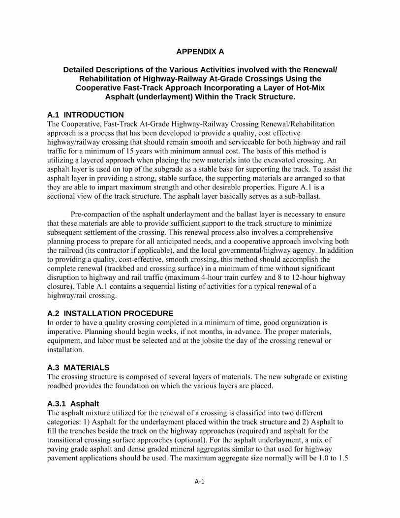
A‐1
APPENDIX A
Detailed Descriptions of the Various Activities involved with the Renewal/ Rehabilitation of Highway-Railway At-Grade Crossings Using the
Cooperative Fast-Track Approach Incorporating a Layer of Hot-Mix Asphalt (underlayment) Within the Track Structure.
A.1 INTRODUCTION The Cooperative, Fast-Track At-Grade Highway-Railway Crossing Renewal/Rehabilitation approach is a process that has been developed to provide a quality, cost effective highway/railway crossing that should remain smooth and serviceable for both highway and rail traffic for a minimum of 15 years with minimum annual cost. The basis of this method is utilizing a layered approach when placing the new materials into the excavated crossing. An asphalt layer is used on top of the subgrade as a stable base for supporting the track. To assist the asphalt layer in providing a strong, stable surface, the supporting materials are arranged so that they are able to impart maximum strength and other desirable properties. Figure A.1 is a sectional view of the track structure. The asphalt layer basically serves as a sub-ballast. Pre-compaction of the asphalt underlayment and the ballast layer is necessary to ensure that these materials are able to provide sufficient support to the track structure to minimize subsequent settlement of the crossing. This renewal process also involves a comprehensive planning process to prepare for all anticipated needs, and a cooperative approach involving both the railroad (its contractor if applicable), and the local governmental/highway agency. In addition to providing a quality, cost-effective, smooth crossing, this method should accomplish the complete renewal (trackbed and crossing surface) in a minimum of time without significant disruption to highway and rail traffic (maximum 4-hour train curfew and 8 to 12-hour highway closure). Table A.1 contains a sequential listing of activities for a typical renewal of a highway/rail crossing. A.2 INSTALLATION PROCEDURE In order to have a quality crossing completed in a minimum of time, good organization is imperative. Planning should begin weeks, if not months, in advance. The proper materials, equipment, and labor must be selected and at the jobsite the day of the crossing renewal or installation. A.3 MATERIALS The crossing structure is composed of several layers of materials. The new subgrade or existing roadbed provides the foundation on which the various layers are placed. A.3.1 Asphalt The asphalt mixture utilized for the renewal of a crossing is classified into two different categories: 1) Asphalt for the underlayment placed within the track structure and 2) Asphalt to fill the trenches beside the track on the highway approaches (required) and asphalt for the transitional crossing surface approaches (optional). For the asphalt underlayment, a mix of paving grade asphalt and dense graded mineral aggregates similar to that used for highway pavement applications should be used. The maximum aggregate size normally will be 1.0 to 1.5
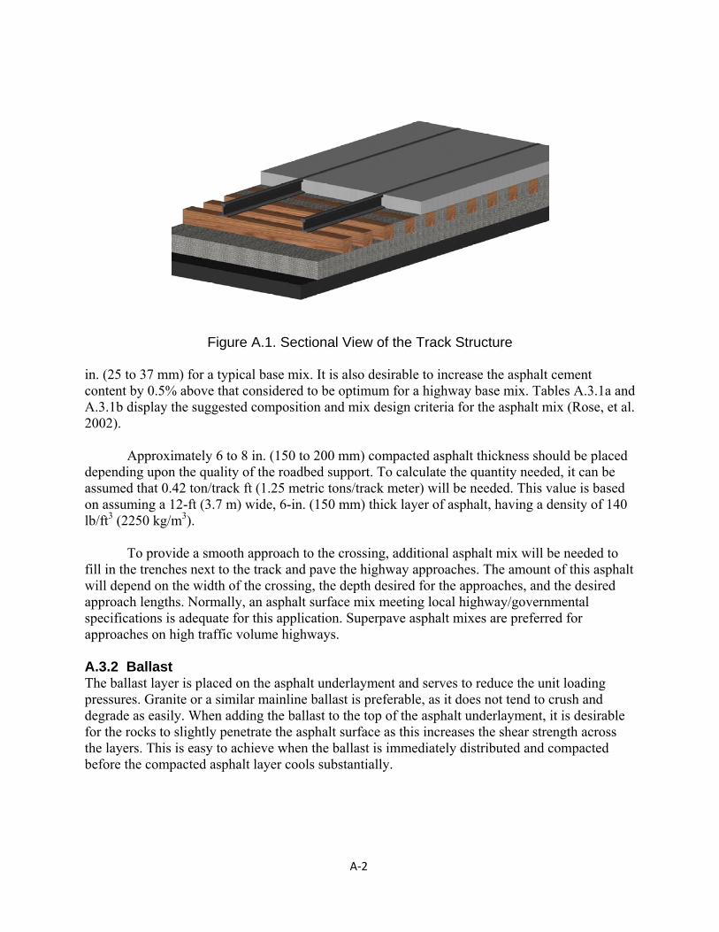
A‐2
Figure A.1. Sectional View of the Track Structure
in. (25 to 37 mm) for a typical base mix. It is also desirable to increase the asphalt cement content by 0.5% above that considered to be optimum for a highway base mix. Tables A.3.1a and A.3.1b display the suggested composition and mix design criteria for the asphalt mix (Rose, et al. 2002). Approximately 6 to 8 in. (150 to 200 mm) compacted asphalt thickness should be placed depending upon the quality of the roadbed support. To calculate the quantity needed, it can be assumed that 0.42 ton/track ft (1.25 metric tons/track meter) will be needed. This value is based on assuming a 12-ft (3.7 m) wide, 6-in. (150 mm) thick layer of asphalt, having a density of 140 lb/ft3 (2250 kg/m3). To provide a smooth approach to the crossing, additional asphalt mix will be needed to fill in the trenches next to the track and pave the highway approaches. The amount of this asphalt will depend on the width of the crossing, the depth desired for the approaches, and the desired approach lengths. Normally, an asphalt surface mix meeting local highway/governmental specifications is adequate for this application. Superpave asphalt mixes are preferred for approaches on high traffic volume highways. A.3.2 Ballast The ballast layer is placed on the asphalt underlayment and serves to reduce the unit loading pressures. Granite or a similar mainline ballast is preferable, as it does not tend to crush and degrade as easily. When adding the ballast to the top of the asphalt underlayment, it is desirable for the rocks to slightly penetrate the asphalt surface as this increases the shear strength across the layers. This is easy to achieve when the ballast is immediately distributed and compacted before the compacted asphalt layer cools substantially.
A‐3
TABLE A.1 Sequential Listing of Activities for a Highway/Rail Crossing Renewal
Time (hours) Activities
2.0 – 2.5
Remove existing crossing surface and track panel (panel will be longer than crossing surface) Excavate trackbed material to approximately 29 in. (750 mm) below top-of-rail Evaluate subgrade support, determine action– No additional activity needed, subgrade is firm and compact Compact subgrade to densify it Add ballast and compact subgrade if subgrade is soft
1.0 – 1.5
Dump, spread, and compact 6 to 8 in. (150 to 200 mm) of asphalt underlayment Dump, spread, and compact 8 to 10 in. (200 to 250 mm) of ballast to grade Position new track panel on compacted ballast and bolt or weld joints
Railroad Open
3.0 – 2.0
Add cribbing ballast, tamp, raise (if desired), and surface track
4.0 – 3.0
Place crossing surface Pave asphalt trenches along both sides of track
Highway Open (pave highway approaches the following day if required)
1.0 – 3.0
Pave asphalt highway approaches the same day (optional)
Highway Open (no further paving required) 6.0 – 12.0
A.3.3 Track Panel The existing track panel that is removed from the crossing should be replaced with a new pre-assembled track panel. This new panel should be sized to fit into the gap created by removing the old track panel while still allowing for some expansion of the rail before it is placed in the gap. It should also be composed of all new ties to provide maximum strength and extended life. The typical panel length is 80 ft (24.3 m). A.3.4 Crossing Surface The actual material that comprises the crossing surface for the highway vehicles can be of several different types. The surface material that is selected depends on the volume and composition of the highway traffic utilizing the crossing. Following are descriptions for the eight surface types most frequently used. These are depicted in Figure A.3.4.
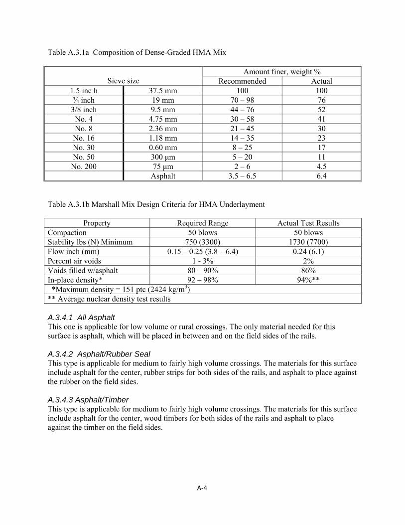
A‐4
Table A.3.1a Composition of Dense-Graded HMA Mix
Sieve size
Amount finer, weight % Recommended Actual
1.5 inc h 37.5 mm 100 100 ¾ inch 19 mm 70 – 98 76
3/8 inch 9.5 mm 44 – 76 52 No. 4 4.75 mm 30 – 58 41 No. 8 2.36 mm 21 – 45 30 No. 16 1.18 mm 14 – 35 23 No. 30 0.60 mm 8 – 25 17 No. 50 300 μm 5 – 20 11 No. 200 75 μm 2 – 6 4.5
Asphalt 3.5 – 6.5 6.4 Table A.3.1b Marshall Mix Design Criteria for HMA Underlayment
Property Required Range Actual Test Results Compaction 50 blows 50 blows Stability lbs (N) Minimum 750 (3300) 1730 (7700) Flow inch (mm) 0.15 – 0.25 (3.8 – 6.4) 0.24 (6.1) Percent air voids 1 - 3% 2% Voids filled w/asphalt 80 – 90% 86% In-place density* 92 – 98% 94%** *Maximum density = 151 ptc (2424 kg/m3) ** Average nuclear density test results A.3.4.1 All Asphalt This one is applicable for low volume or rural crossings. The only material needed for this surface is asphalt, which will be placed in between and on the field sides of the rails. A.3.4.2 Asphalt/Rubber Seal This type is applicable for medium to fairly high volume crossings. The materials for this surface include asphalt for the center, rubber strips for both sides of the rails, and asphalt to place against the rubber on the field sides. A.3.4.3 Asphalt/Timber This type is applicable for medium to fairly high volume crossings. The materials for this surface include asphalt for the center, wood timbers for both sides of the rails and asphalt to place against the timber on the field sides.
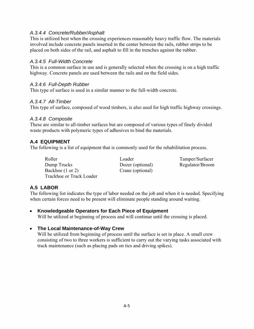
A‐5
A.3.4.4 Concrete/Rubber/Asphalt This is utilized best when the crossing experiences reasonably heavy traffic flow. The materials involved include concrete panels inserted in the center between the rails, rubber strips to be placed on both sides of the rail, and asphalt to fill in the trenches against the rubber. A.3.4.5 Full-Width Concrete This is a common surface in use and is generally selected when the crossing is on a high traffic highway. Concrete panels are used between the rails and on the field sides. A.3.4.6 Full-Depth Rubber This type of surface is used in a similar manner to the full-width concrete. A.3.4.7 All-Timber This type of surface, composed of wood timbers, is also used for high traffic highway crossings. A.3.4.8 Composite These are similar to all-timber surfaces but are composed of various types of finely divided waste products with polymeric types of adhesives to bind the materials. A.4 EQUIPMENT The following is a list of equipment that is commonly used for the rehabilitation process. Roller Loader Tamper/Surfacer Dump Trucks Dozer (optional) Regulator/Broom Backhoe (1 or 2) Crane (optional) Trackhoe or Track Loader A.5 LABOR The following list indicates the type of labor needed on the job and when it is needed. Specifying when certain forces need to be present will eliminate people standing around waiting. Knowledgeable Operators for Each Piece of Equipment Will be utilized at beginning of process and will continue until the crossing is placed. The Local Maintenance-of-Way Crew
Will be utilized from beginning of process until the surface is set in place. A small crew consisting of two to three workers is sufficient to carry out the varying tasks associated with track maintenance (such as placing pads on ties and driving spikes).
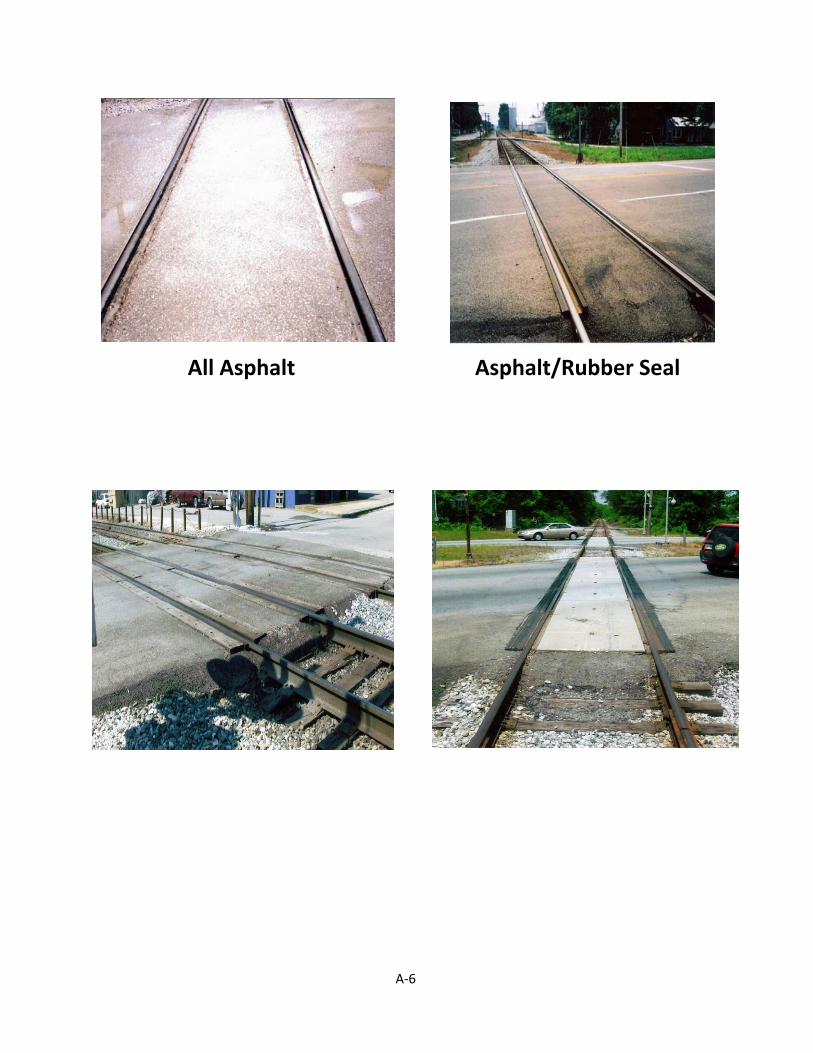
A‐6
All Asphalt Asphalt/Rubber Seal
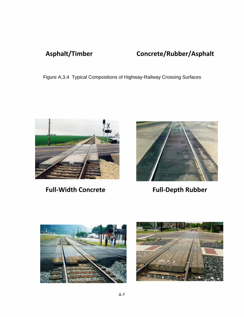
A‐7
Asphalt/Timber Concrete/Rubber/Asphalt
Figure A.3.4 Typical Compositions of Highway-Railway Crossing Surfaces
Full‐Width Concrete Full‐Depth Rubber
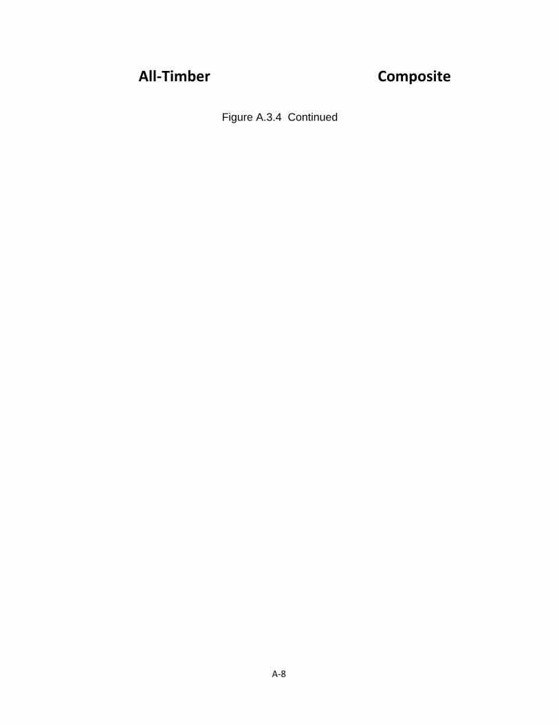
A‐8
All‐Timber Composite
Figure A.3.4 Continued
A‐9
Signal Crew Will be required if the crossing has active warning devices such as flashing lights, bells, and/or gates. Expect to have them available once work commences in order to disable the wires for the warning devices. It is good practice to have them available throughout the duration of the excavation in case any problems occur due to buried cables. They should also be available at the end of work to reconnect any disabled warning devices.
Welders Will be utilized if the rail from the panel is to be welded to the rail from the existing track on the same day as the rehabilitation. Expect to have them on hand once the tamping and surfacing step has been completed (approximately 5 to 6 hours from the start of the work).
Asphalt Crew
During the placement of the asphalt underlayment layer, no members from the asphalt crew need to be available. Later, when paving the trenches and approaches, the crew will be utilized to perform the hand work.
Traffic Control
If needed, will be required throughout the duration of crossing rehabilitation. A.6 ACTIVITIES PRIOR TO REHABILIATION Several activities must be considered in the planning process and will need to be completed before the actual rehabilitation process. The following list describes these tasks in more detail. Notification
This includes planning how the highway traffic will be diverted around the closed crossing. The public should be informed of the date and time that this will be done via the local newspapers, radio stations, and television stations. Also, the signage used to divert the traffic should be placed in the desired locations previous to the closing of the crossing and covered until the actual closing occurs. Variable message signs are particularly appropriate.
Track Time Work orders should be obtained by the railroad company prior to closing the crossing. This is necessary from a safety standpoint, and also allows for the determination of when work should begin.
Cut Rail
This should occur prior to the morning when work begins. By selecting the placement of the cuts, the exact length will be known for building the new panel. Actually, making the cuts and using joint bars to keep the rail in service can save time when work begins and keeps the track out of service for a shorter amount of time.
Saw Pavement
To allow for adequate room for excavation, the cuts should be made seven feet from the rail on both sides. This also should occur prior to the morning when work begins since this
A‐10
activity will save time by allowing excavation to begin immediately after closing the highway.
Material Storage
All materials except for the asphalt should be stored at or near the site for ease of accessibility. By having all materials in ready supply at the jobsite, no travel time delays are experienced in retrieving the needed materials.
A.7 REHABILITATION ACTIVITIES Once proper planning has been performed along with all of the previous activities, the following activities should be performed on the day of the rehabilitation. Removal and Excavation
The first step is to remove the old crossing surface and track panel. Normally, the trackbed is excavated an approximate depth of 28 in. (70 cm) below the top of rail. Backhoes, hydraulic excavators, track loaders, and dozers can all be utilized during these activities.
Dump trucks (either highway or hi-rail) are utilized to haul off fouled ballast and other excavated materials.
Compact Subgrade with Vibratory Roller (if required) Dump and Spread Asphalt
The asphalt layer should extend 1 ½ to 2 ft (0.45 to 0.6 m) beyond the end of the ties. It should also extend a specified distance beyond the ends of the crossing to provide a transition zone. A minimum distance of 25 to 100 ft (8 to 30 m) is recommended (Asphalt Institute, 1998). The spreading of the asphalt can be accomplished by using a backhoe, dozer blade, loader bucket, or excavator bucket.
Compact Asphalt
When compacting the asphalt, a standard roller, preferably a steel wheeled, vibratory type is preferred. A compaction level of 95% is desirable and this is usually achieved if compaction occurs while the mix is 200 to 300°F (95 to 150°C). After compaction, the layer of asphalt will constitute the foundation for the crossing. It is also desirable to leave a slight crown or side slope on the asphalt for drainage.
Dump and Spread Ballast
Using the loader, ballast should be dumped on top of the asphalt so that an 8 to 12 in. (200 to 300 mm) layer will be left after compaction. As with the asphalt layer, the spreading of the ballast can be accomplished by using a backhoe, dozer blade, loader bucket, or excavator bucket.
Compact Ballast
The same roller used on the asphalt for compaction can be used for the ballast compaction.
A‐11
Replace Track Panel The on-site equipment can be used to maneuver the new track panel into place on top of the compacted ballast. If the rail has expanded such that the panel will not fit, the excess will need to be trimmed.
Bolt Joints
Once the panel is in place, the joint bars temporarily secure the new panel to the old rail. Add Cribbing Ballast
Additional ballast is dumped into the track to provide for the track raise and adjustments and to fill in the cribs between the ties.
Surface, Tamp, and Broom
If track needs to be raised, at this point the raise can be implemented. Install Surface
Several different types of surfaces are commonly utilized. Approaches
Sweep the old pavement if needed and apply a tack coat to the surface. Once this is completed, paving may begin. The asphalt may be placed either by truck, by hand, or by a paving machine. Compaction can be achieved with the same vibratory roller used previously for the asphalt and ballast in the trench. It is recommended that if the approaches are to be very long, a paving machine be used.
Spray Water
The final step is to spray water on the asphalt to cool it. By performing this step, rutting of the new asphalt may be minimized if the highway is immediately opened to traffic. This activity is normally not necessary unless the crossing will be subjected to turning highway traffic.
A.8 CLOSURE Table 3.2 provides a summary of these activities and provides a time scale. Also, Figures 3.2a and 3.2b provide a collection of pictures representing the different stages of the renewal process. Finally, several sample projects are described and illustrated in succeeding Appendices. It should be noted that some activities can be conducted concurrently. For example, the rails can be sawed (cut) in preparation for removing the old panel while the old crossing surface is being removed. Also, if one end of the asphalt underlayment has already been compacted, some ballast can be dumped on this end while the other end is being compacted. Additionally, while the ballast is being compacted, the new panel can be positioned near the crossing. By overlapping some of the activities, the time the track is out of service can be minimized.
B‐1
APPENDIX B
Representative Projects
Central and Western Kentucky Crossings
US 421/25 (Main Street) – Richmond, KY, September 2000
US 41 – Sebree, KY, August 2004
KY 595 – Berea, KY, April 2002
Rosemont Garden – Lexington, KY, July 2002
Waller Avenue – Lexington, KY, August 2002
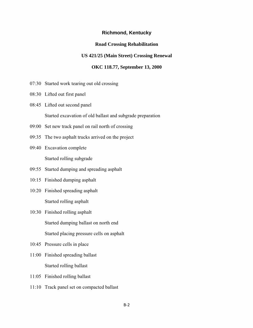
B‐2
Richmond, Kentucky
Road Crossing Rehabilitation
US 421/25 (Main Street) Crossing Renewal
OKC 118.77, September 13, 2000
07:30 Started work tearing out old crossing
08:30 Lifted out first panel
08:45 Lifted out second panel
Started excavation of old ballast and subgrade preparation
09:00 Set new track panel on rail north of crossing
09:35 The two asphalt trucks arrived on the project
09:40 Excavation complete
Started rolling subgrade
09:55 Started dumping and spreading asphalt
10:15 Finished dumping asphalt
10:20 Finished spreading asphalt
Started rolling asphalt
10:30 Finished rolling asphalt
Started dumping ballast on north end
Started placing pressure cells on asphalt
10:45 Pressure cells in place
11:00 Finished spreading ballast
Started rolling ballast
11:05 Finished rolling ballast
11:10 Track panel set on compacted ballast
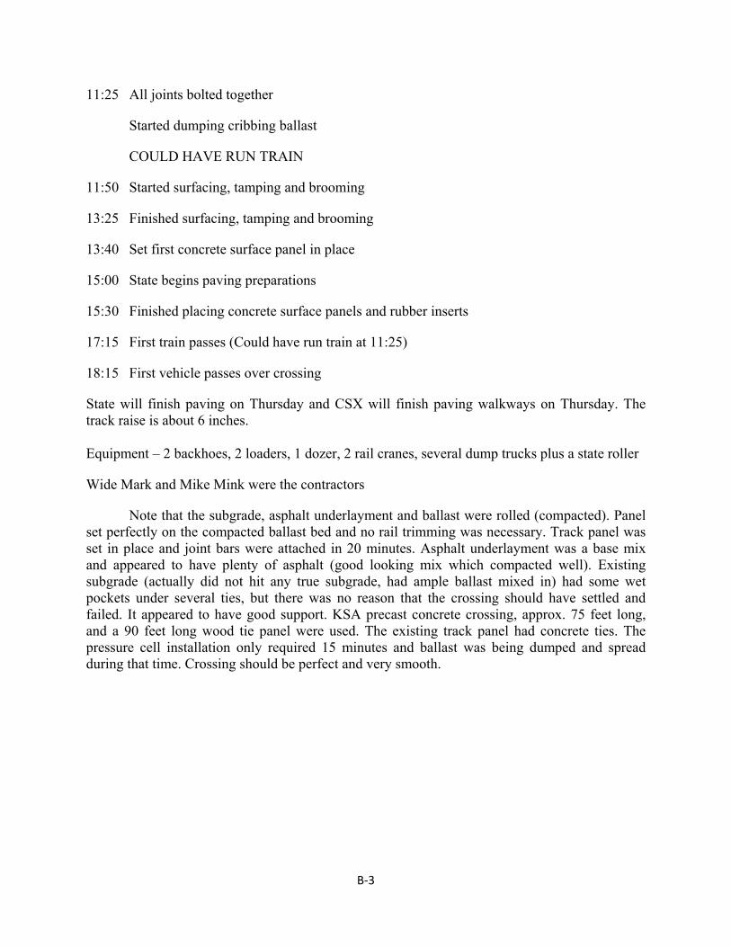
B‐3
11:25 All joints bolted together
Started dumping cribbing ballast
COULD HAVE RUN TRAIN
11:50 Started surfacing, tamping and brooming
13:25 Finished surfacing, tamping and brooming
13:40 Set first concrete surface panel in place
15:00 State begins paving preparations
15:30 Finished placing concrete surface panels and rubber inserts
17:15 First train passes (Could have run train at 11:25)
18:15 First vehicle passes over crossing
State will finish paving on Thursday and CSX will finish paving walkways on Thursday. The track raise is about 6 inches. Equipment – 2 backhoes, 2 loaders, 1 dozer, 2 rail cranes, several dump trucks plus a state roller
Wide Mark and Mike Mink were the contractors
Note that the subgrade, asphalt underlayment and ballast were rolled (compacted). Panel set perfectly on the compacted ballast bed and no rail trimming was necessary. Track panel was set in place and joint bars were attached in 20 minutes. Asphalt underlayment was a base mix and appeared to have plenty of asphalt (good looking mix which compacted well). Existing subgrade (actually did not hit any true subgrade, had ample ballast mixed in) had some wet pockets under several ties, but there was no reason that the crossing should have settled and failed. It appeared to have good support. KSA precast concrete crossing, approx. 75 feet long, and a 90 feet long wood tie panel were used. The existing track panel had concrete ties. The pressure cell installation only required 15 minutes and ballast was being dumped and spread during that time. Crossing should be perfect and very smooth.
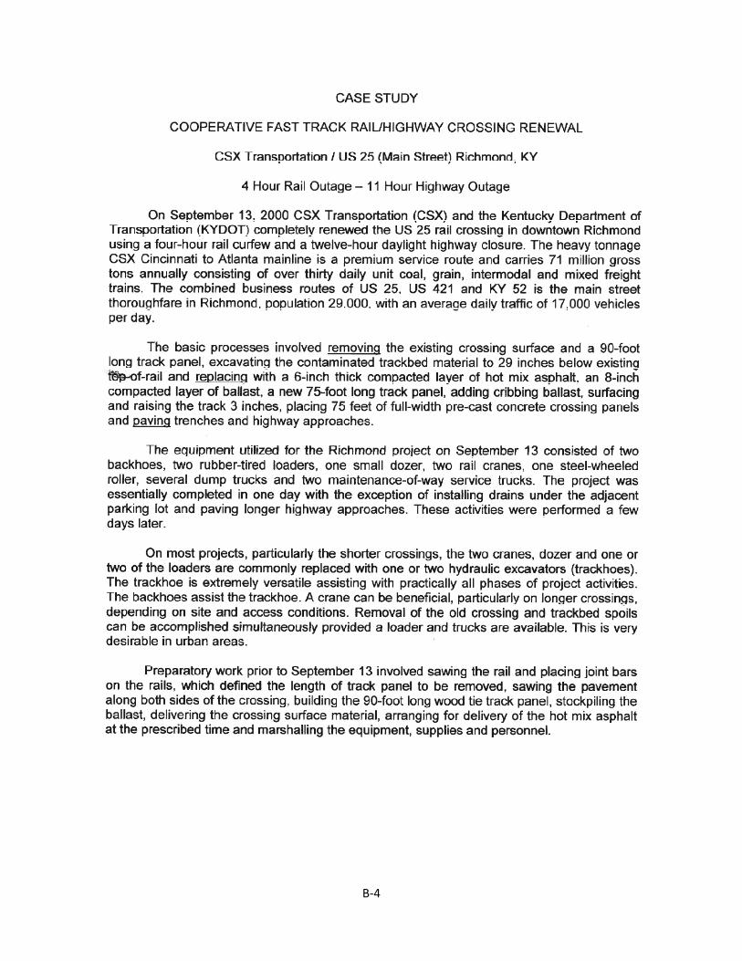
B‐4
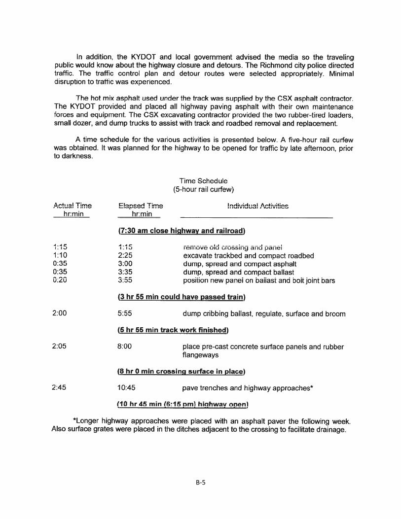
B‐5
B‐6
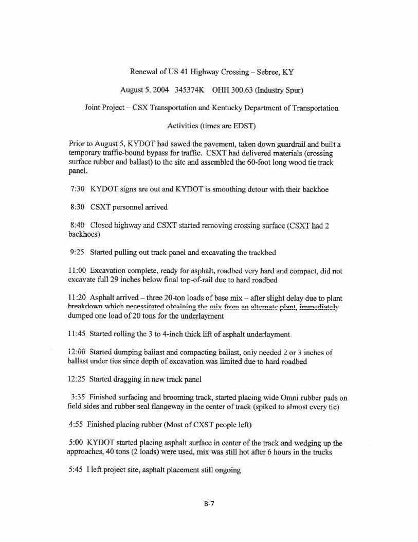
B‐7
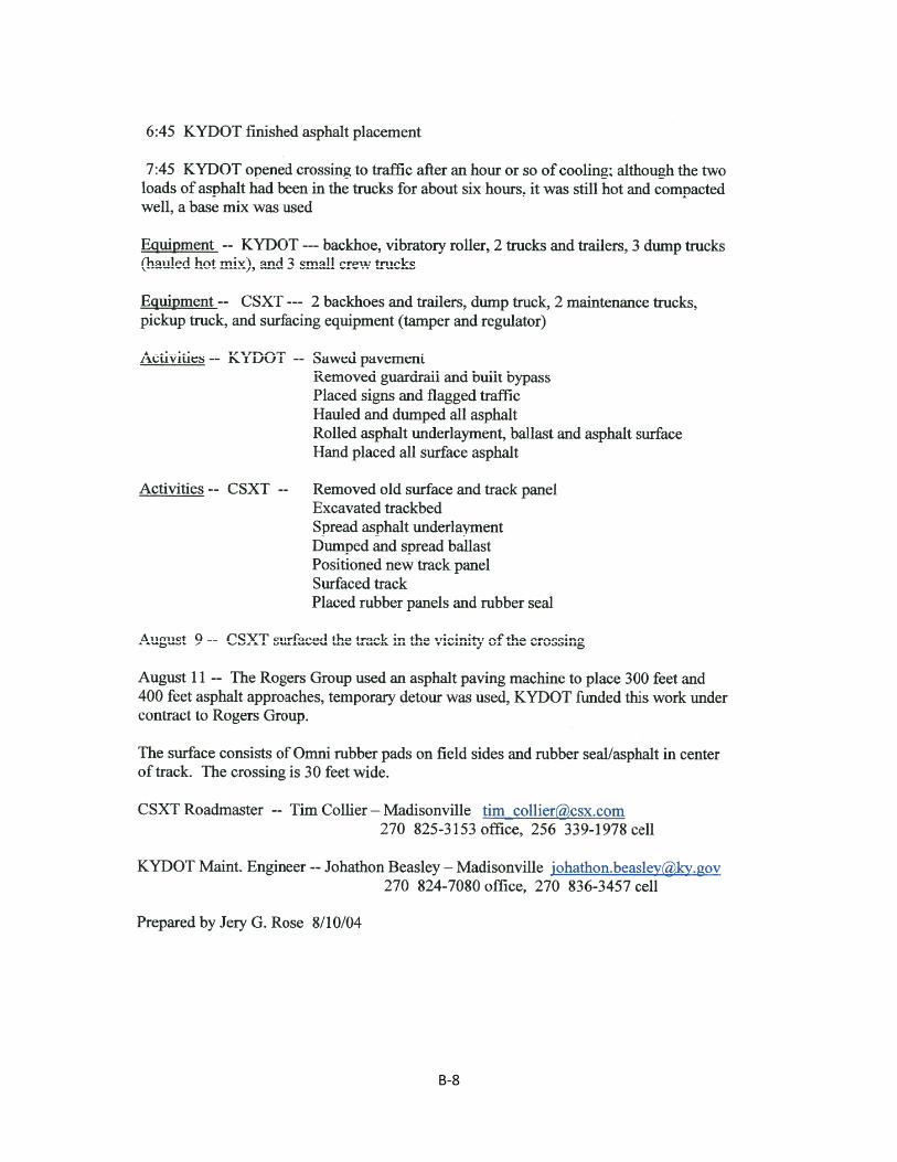
B‐8
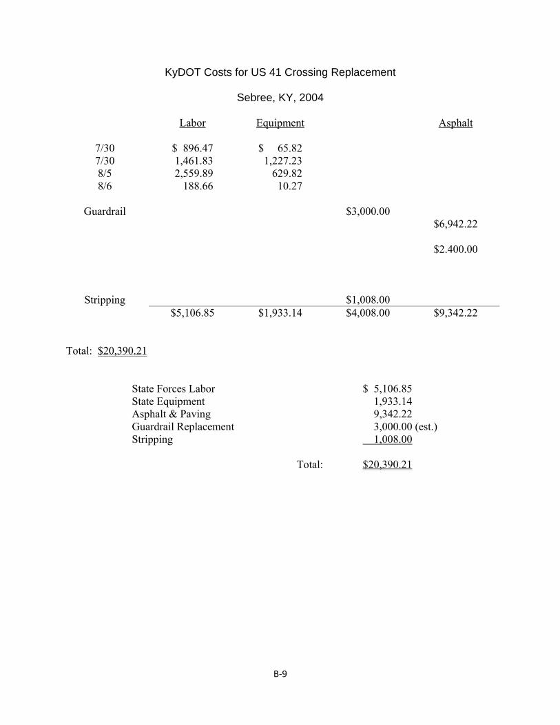
B‐9
KyDOT Costs for US 41 Crossing Replacement
Sebree, KY, 2004
Labor Equipment Asphalt
7/30 7/30 8/5 8/6
Guardrail
Stripping
$ 896.47 1,461.83 2,559.89 188.66
$ 65.82 1,227.23 629.82 10.27
$3,000.00
$1,008.00
$6,942.22
$2.400.00
$5,106.85 $1,933.14 $4,008.00 $9,342.22 Total: $20,390.21 State Forces Labor $ 5,106.85 State Equipment 1,933.14 Asphalt & Paving 9,342.22 Guardrail Replacement 3,000.00 (est.) Stripping 1,008.00 Total: $20,390.21
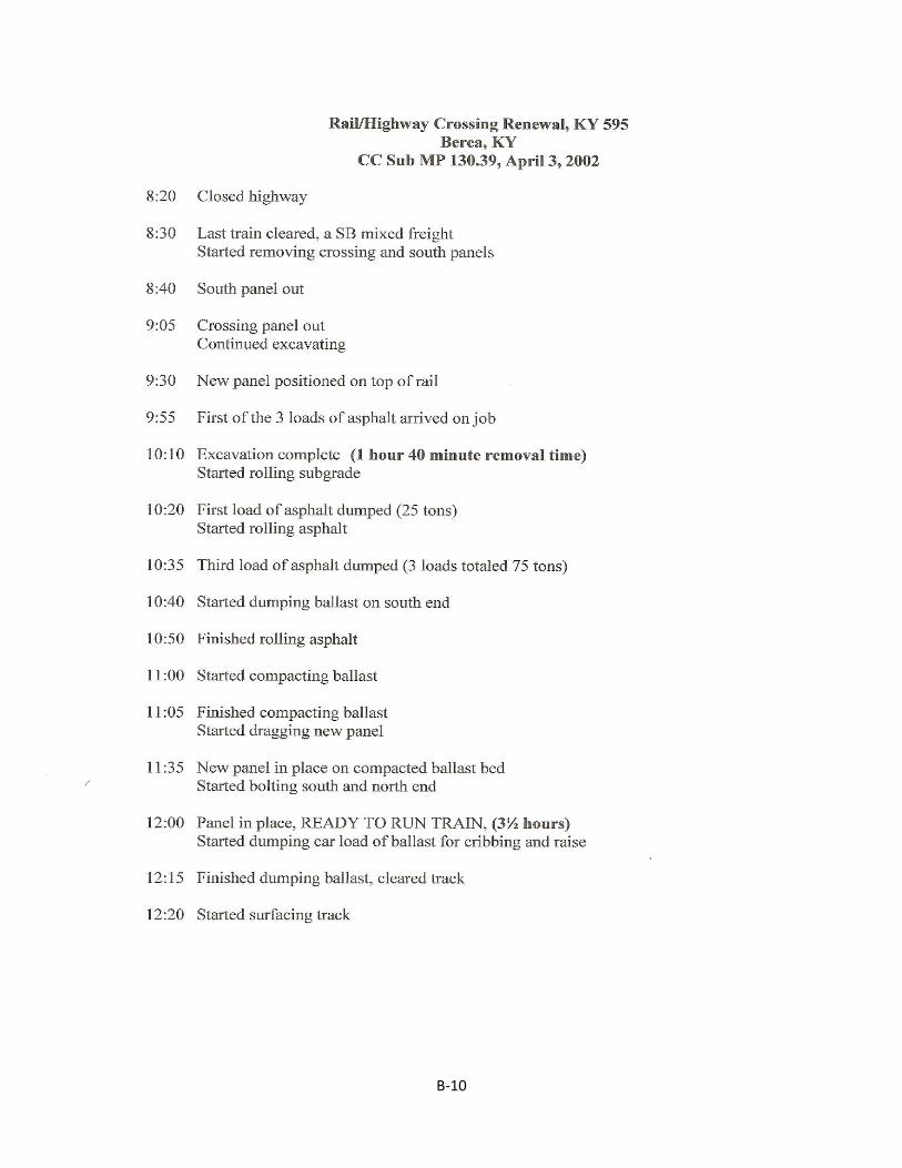
B‐10
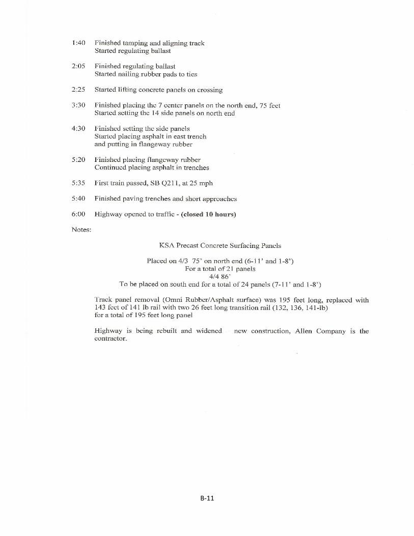
B‐11
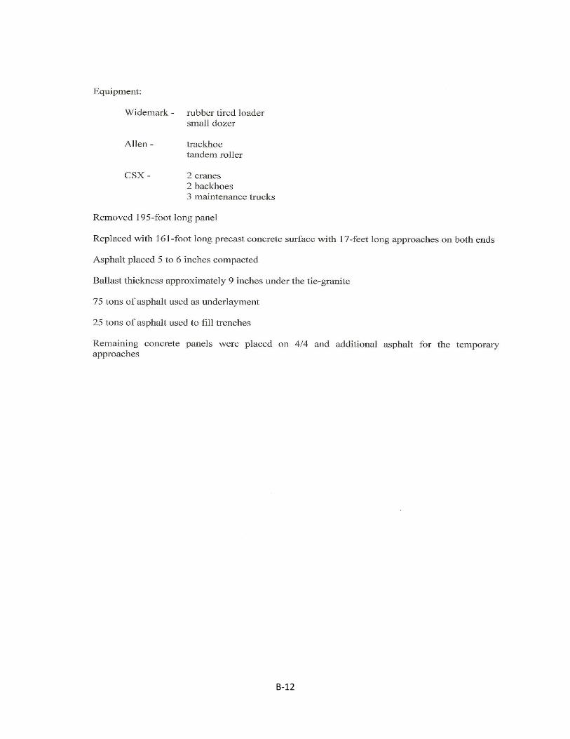
B‐12
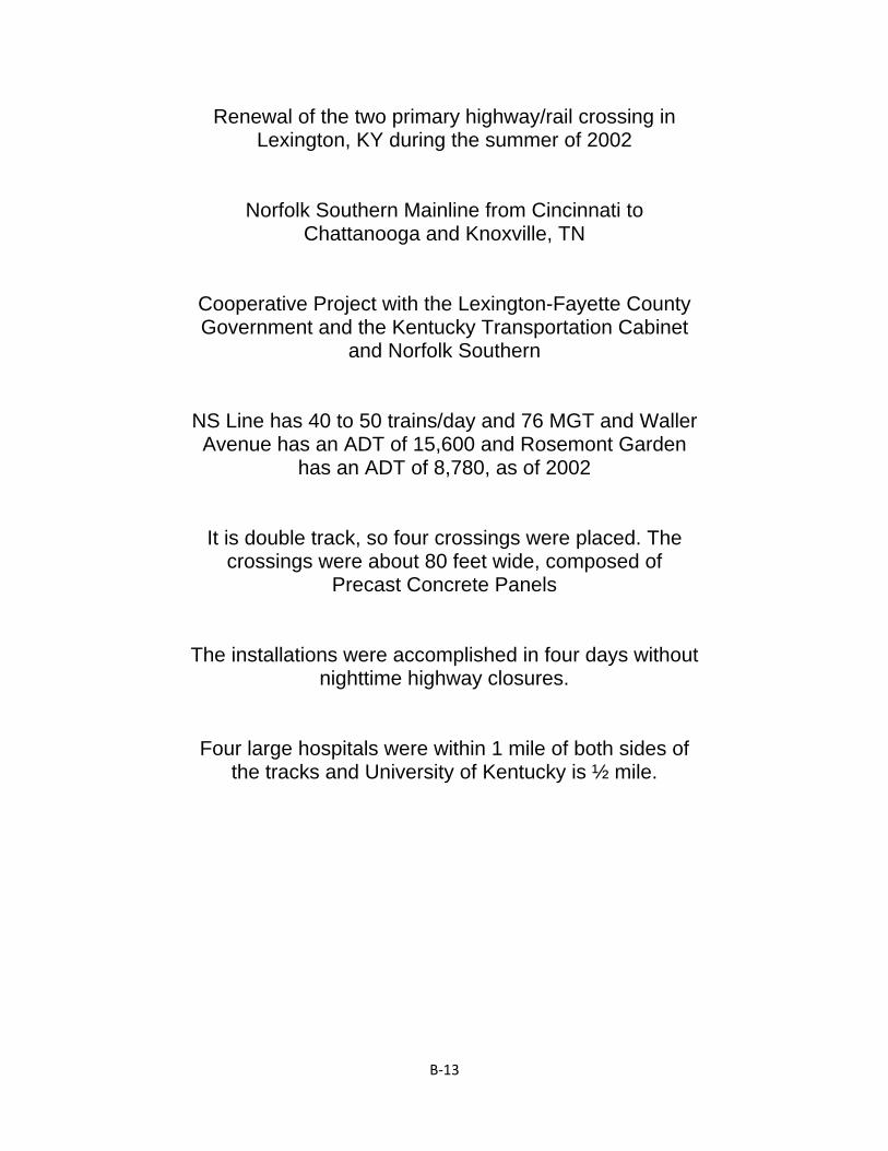
B‐13
Renewal of the two primary highway/rail crossing in Lexington, KY during the summer of 2002
Norfolk Southern Mainline from Cincinnati to Chattanooga and Knoxville, TN
Cooperative Project with the Lexington-Fayette County Government and the Kentucky Transportation Cabinet
and Norfolk Southern
NS Line has 40 to 50 trains/day and 76 MGT and Waller Avenue has an ADT of 15,600 and Rosemont Garden
has an ADT of 8,780, as of 2002
It is double track, so four crossings were placed. The crossings were about 80 feet wide, composed of
Precast Concrete Panels
The installations were accomplished in four days without nighttime highway closures.
Four large hospitals were within 1 mile of both sides of the tracks and University of Kentucky is ½ mile.
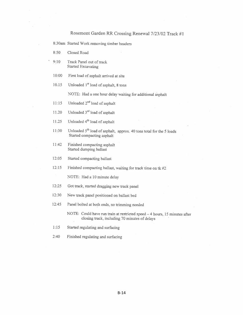
B‐14
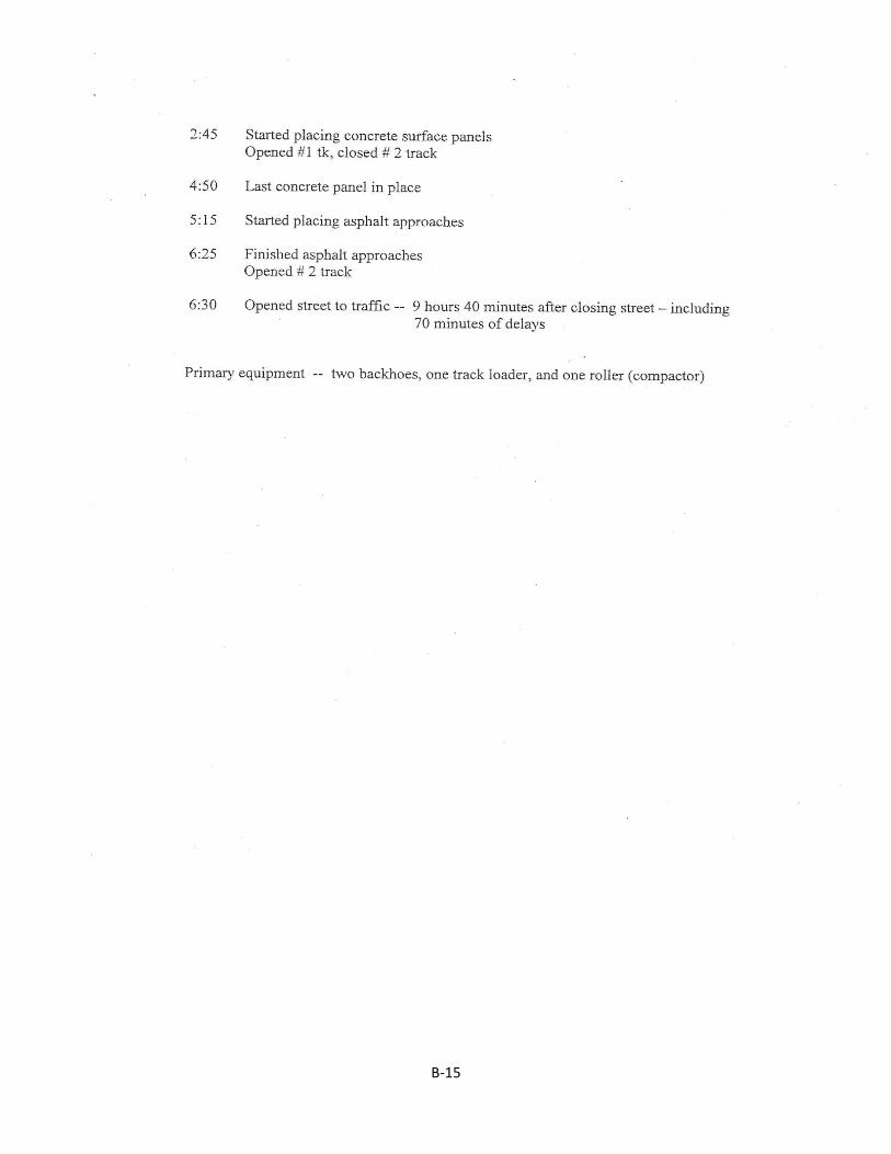
B‐15
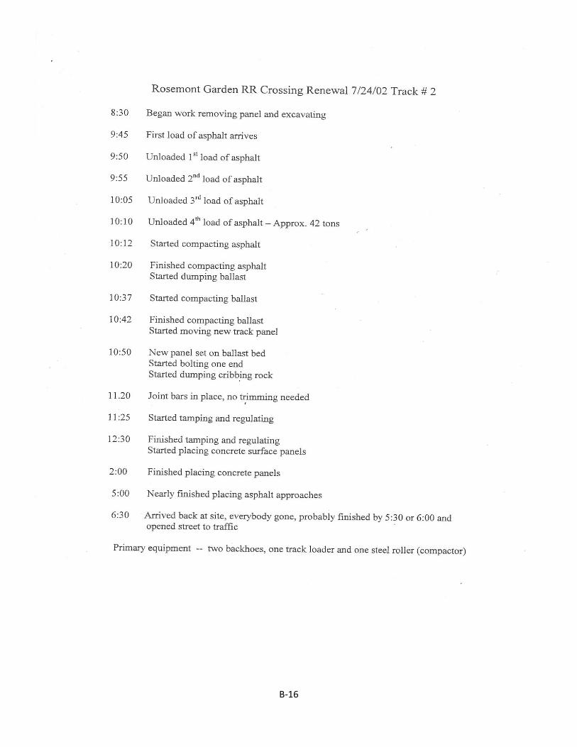
B‐16
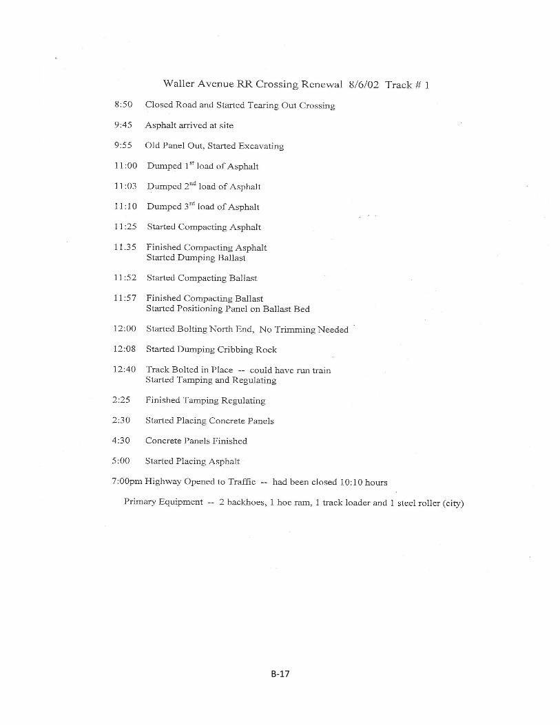
B‐17
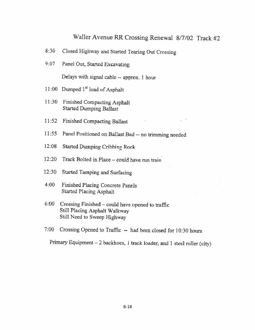
B‐18
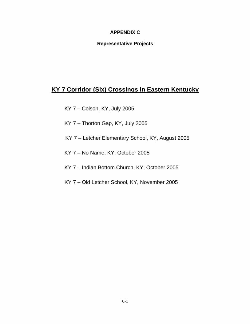
C‐1
APPENDIX C
Representative Projects
KY 7 Corridor (Six) Crossings in Eastern Kentucky
KY 7 – Colson, KY, July 2005
KY 7 – Thorton Gap, KY, July 2005
KY 7 – Letcher Elementary School, KY, August 2005
KY 7 – No Name, KY, October 2005
KY 7 – Indian Bottom Church, KY, October 2005
KY 7 – Old Letcher School, KY, November 2005
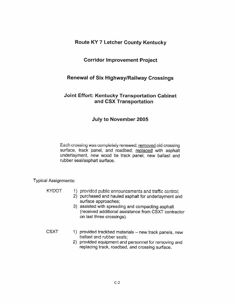
C‐2
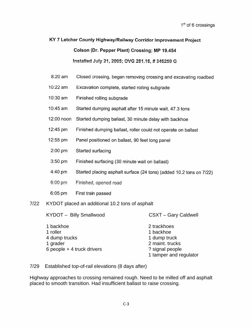
C‐3
7/22 KYDOT placed an additional 10.2 tons of asphalt KYDOT – Billy Smallwood CSXT – Gary Caldwell 1 backhoe 2 trackhoes 1 roller 1 backhoe 4 dump trucks 1 dump truck 1 grader 2 maint. trucks 6 people + 4 truck drivers ? signal people 1 tamper and regulator 7/29 Established top-of-rail elevations (8 days after) Highway approaches to crossing remained rough. Need to be milled off and asphalt placed to smooth transition. Had insufficient ballast to raise crossing.
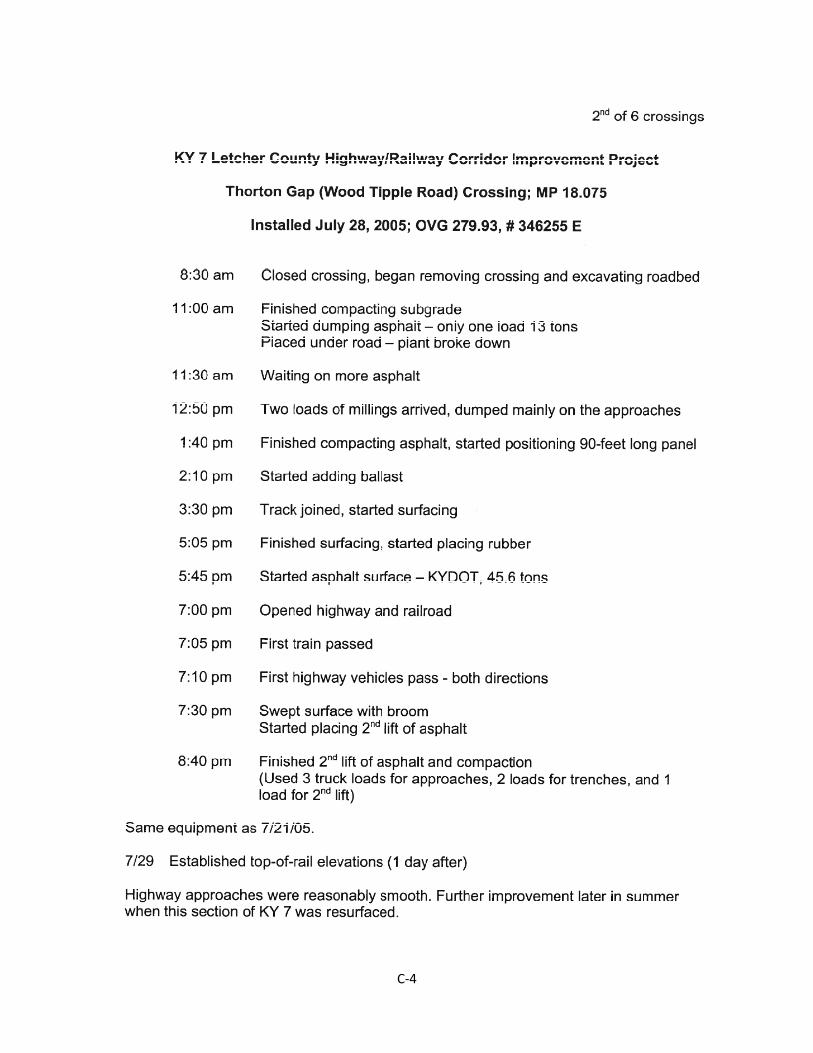
C‐4
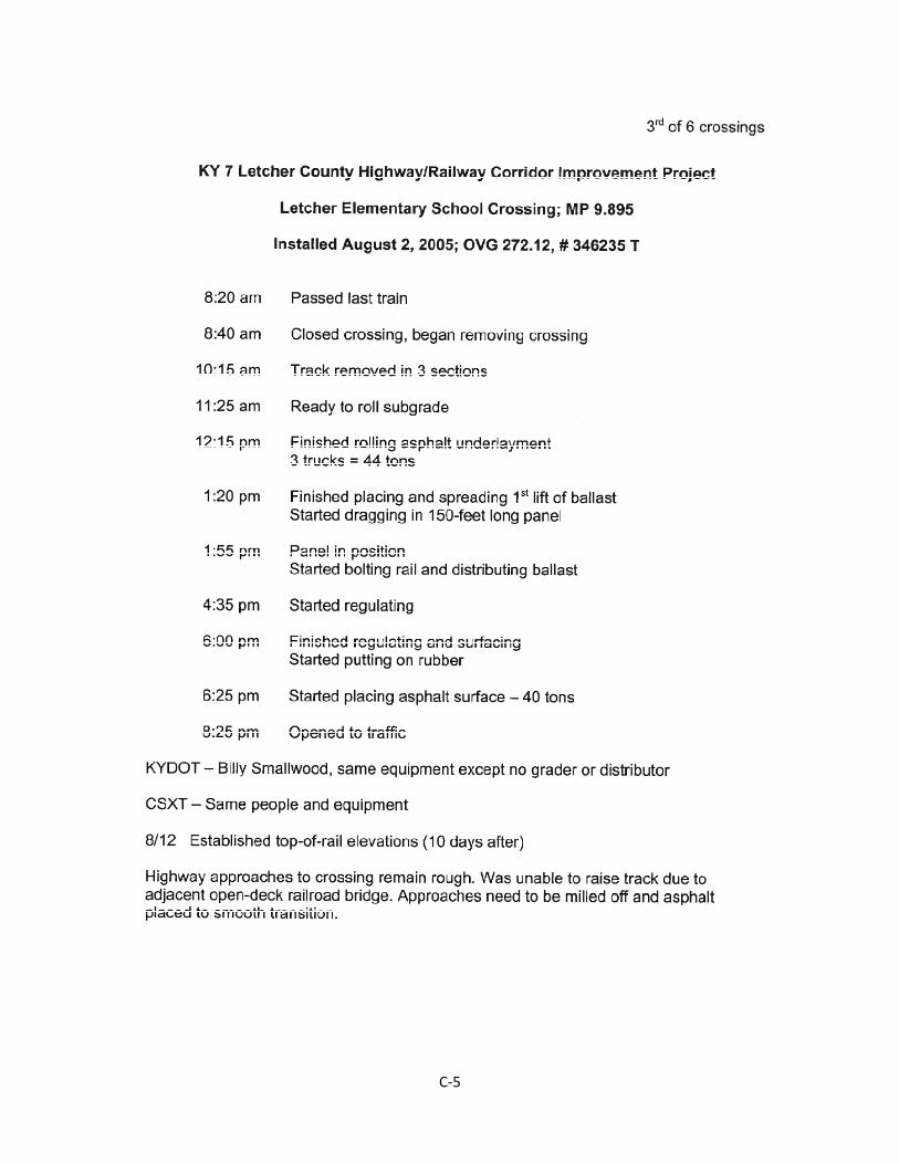
C‐5
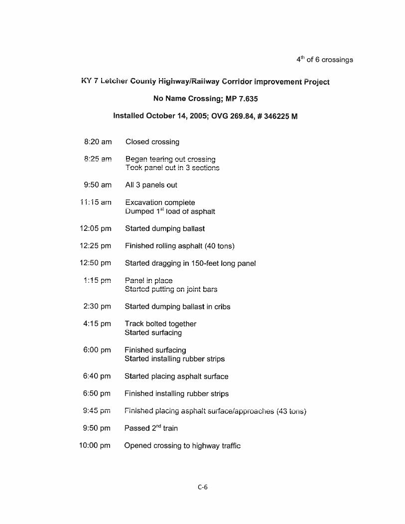
C‐6
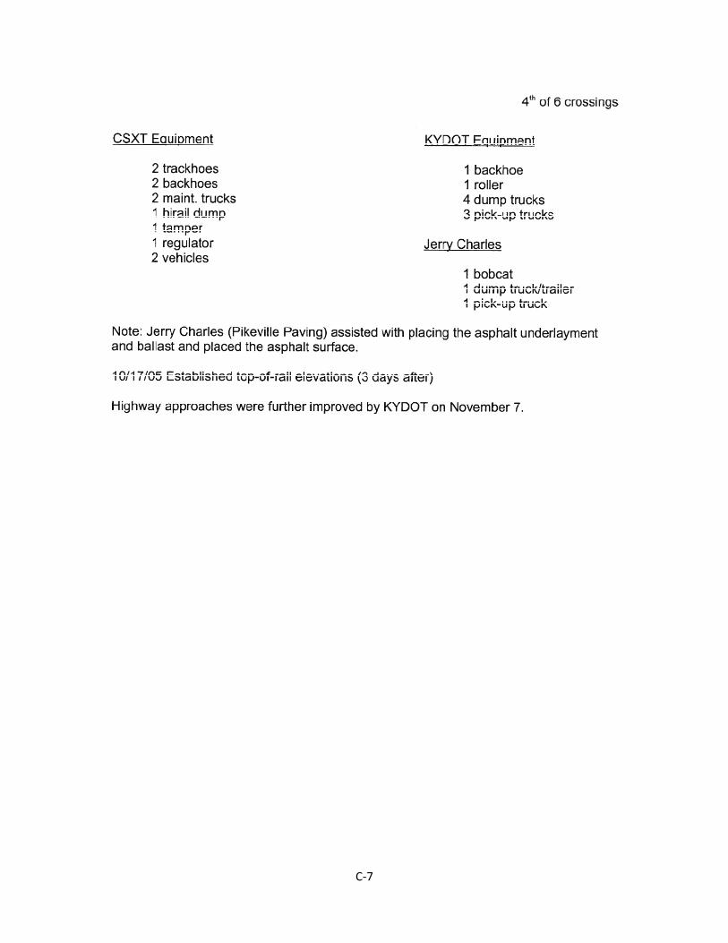
C‐7
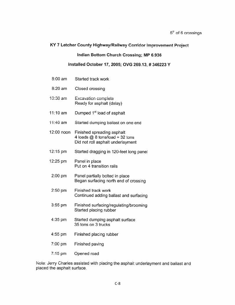
C‐8
C‐9
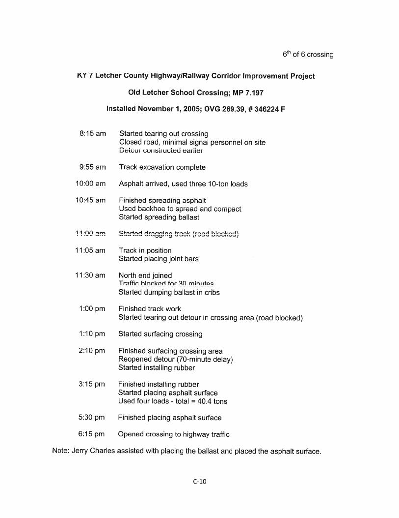
C‐10
C‐11
D‐1
APPENDIX D
Representative Projects
Out-of-State Crossings
US 129 – Alcoa/Maryville, TN, June 2001
4th, 5th, & 6th Avenues – Huntington, WV, August 2000
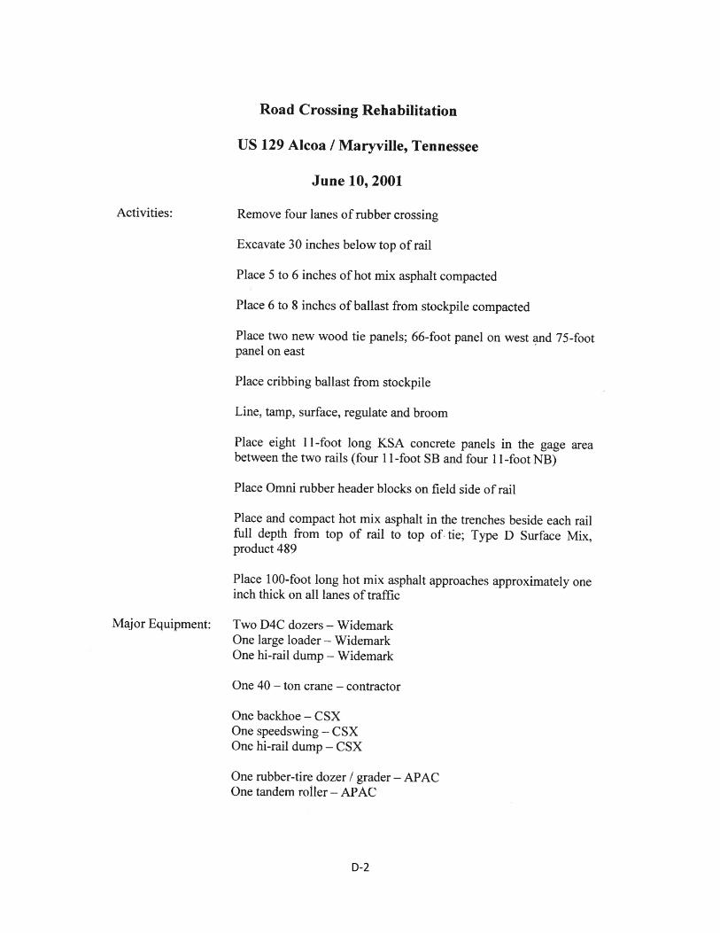
D‐2
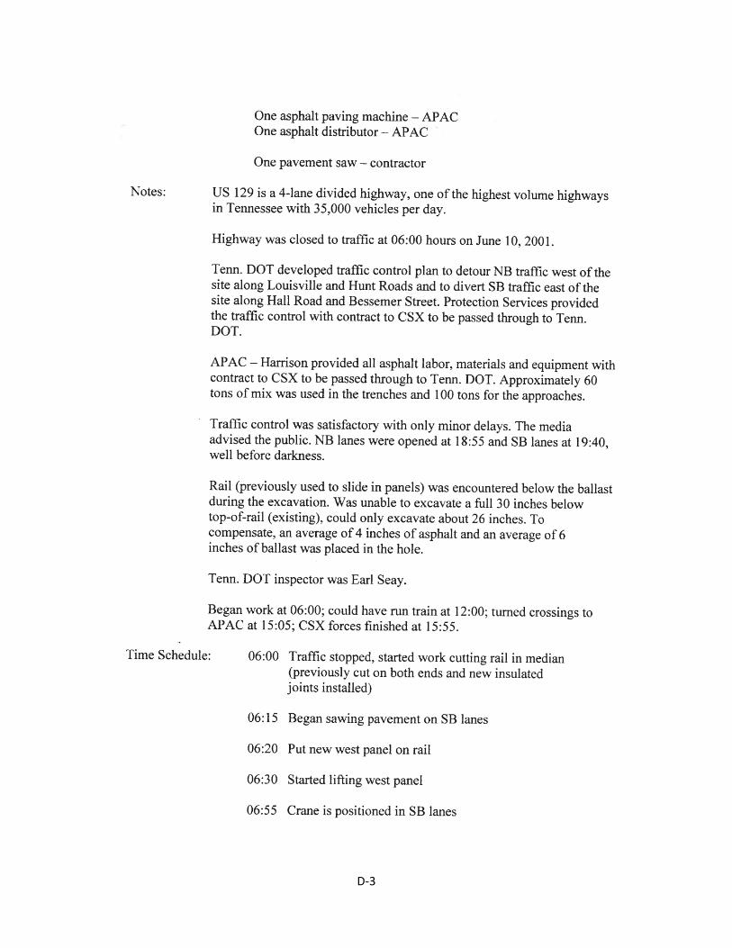
D‐3
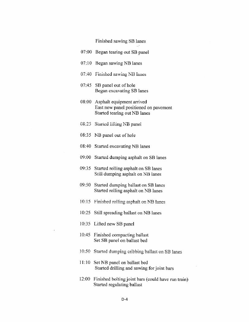
D‐4
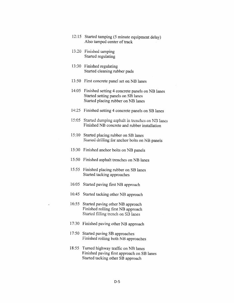
D‐5
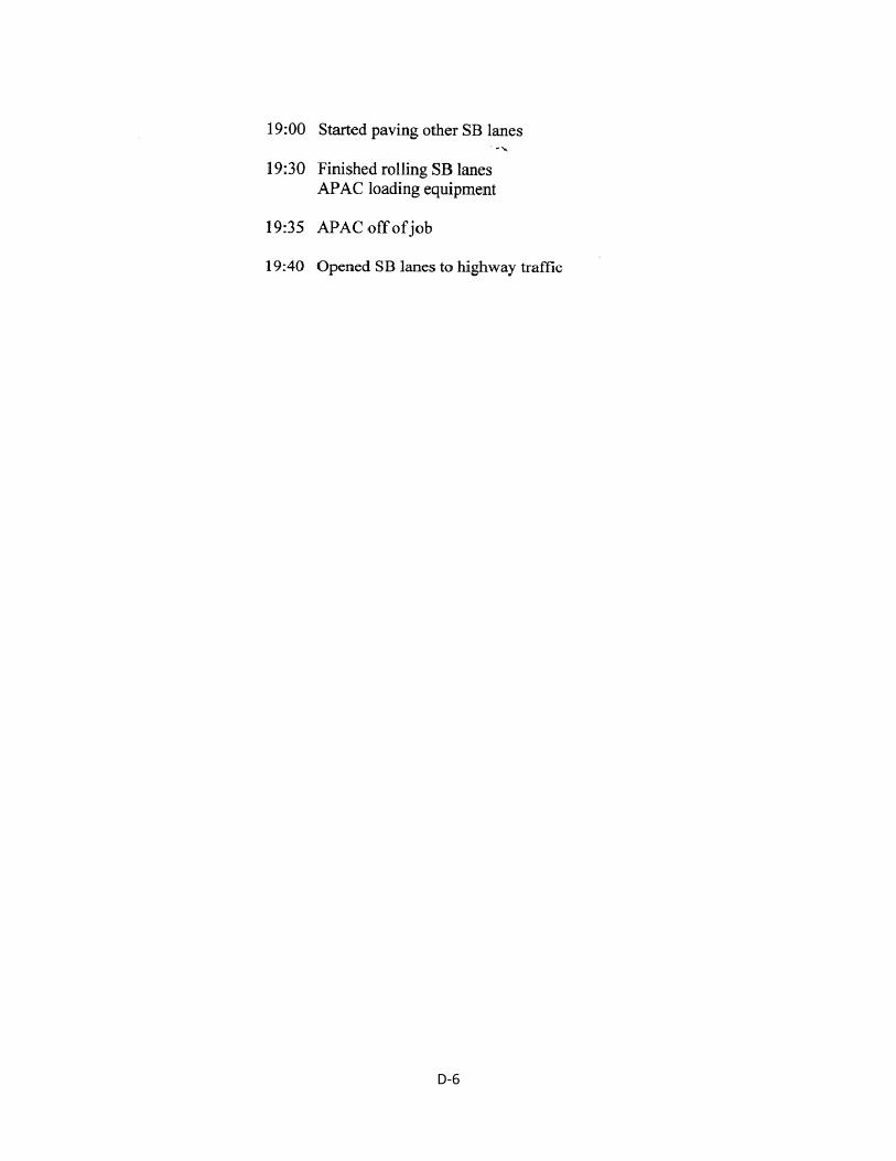
D‐6
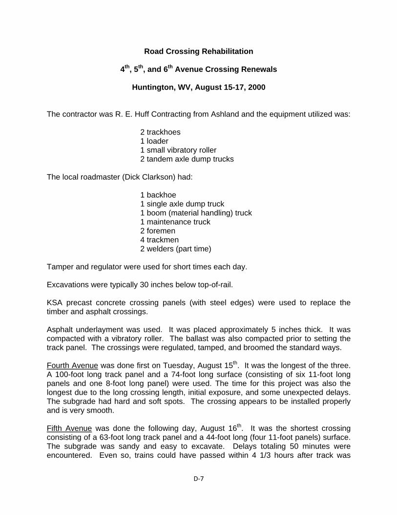
D‐7
Road Crossing Rehabilitation
4th, 5th, and 6th Avenue Crossing Renewals
Huntington, WV, August 15-17, 2000 The contractor was R. E. Huff Contracting from Ashland and the equipment utilized was: 2 trackhoes 1 loader 1 small vibratory roller 2 tandem axle dump trucks The local roadmaster (Dick Clarkson) had: 1 backhoe 1 single axle dump truck 1 boom (material handling) truck 1 maintenance truck 2 foremen 4 trackmen 2 welders (part time) Tamper and regulator were used for short times each day. Excavations were typically 30 inches below top-of-rail. KSA precast concrete crossing panels (with steel edges) were used to replace the timber and asphalt crossings. Asphalt underlayment was used. It was placed approximately 5 inches thick. It was compacted with a vibratory roller. The ballast was also compacted prior to setting the track panel. The crossings were regulated, tamped, and broomed the standard ways. Fourth Avenue was done first on Tuesday, August 15th. It was the longest of the three. A 100-foot long track panel and a 74-foot long surface (consisting of six 11-foot long panels and one 8-foot long panel) were used. The time for this project was also the longest due to the long crossing length, initial exposure, and some unexpected delays. The subgrade had hard and soft spots. The crossing appears to be installed properly and is very smooth. Fifth Avenue was done the following day, August 16th. It was the shortest crossing consisting of a 63-foot long track panel and a 44-foot long (four 11-foot panels) surface. The subgrade was sandy and easy to excavate. Delays totaling 50 minutes were encountered. Even so, trains could have passed within 4 1/3 hours after track was
D‐8
taken out of surface. With the exception of welding the panels, the project was finished in about 7½ to 8 hours and highway traffic could have passed. Third Avenue was done on Thursday, August 17th. It was intermediate in size, consisting of a 66-foot long track panel and a 56-foot long crossing surface. During the excavation, an old side track was uncovered and the end of the ties had to be sawed off with a chain saw which increased the excavation time. The subgrade had hard and soft spots. There was a 40-minute delay waiting for the asphalt. The ballast supply was closeby. Although a detailed time log was not maintained for this project, the total time for installing the crossing was similar to Fifth Avenue, or around 7½ to 8 hours. The crossing surfaces were not welded together since the crossing is on a curve. I was not present for this project and this information was obtained from the roadmaster. Detailed time logs for the Fourth and Fifth Avenue projects follow.
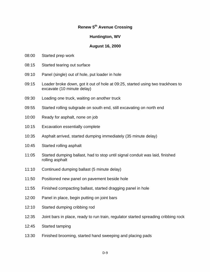
D‐9
Renew 5th Avenue Crossing
Huntington, WV
August 16, 2000 08:00 Started prep work 08:15 Started tearing out surface 09:10 Panel (single) out of hole, put loader in hole 09:15 Loader broke down, got it out of hole at 09:25, started using two trackhoes to
excavate (10 minute delay) 09:30 Loading one truck, waiting on another truck 09:55 Started rolling subgrade on south end, still excavating on north end 10:00 Ready for asphalt, none on job 10:15 Excavation essentially complete 10:35 Asphalt arrived, started dumping immediately (35 minute delay) 10:45 Started rolling asphalt 11:05 Started dumping ballast, had to stop until signal conduit was laid, finished
rolling asphalt 11:10 Continued dumping ballast (5 minute delay) 11:50 Positioned new panel on pavement beside hole 11:55 Finished compacting ballast, started dragging panel in hole 12:00 Panel in place, begin putting on joint bars 12:10 Started dumping cribbing rod 12:35 Joint bars in place, ready to run train, regulator started spreading cribbing rock 12:45 Started tamping 13:30 Finished brooming, started hand sweeping and placing pads
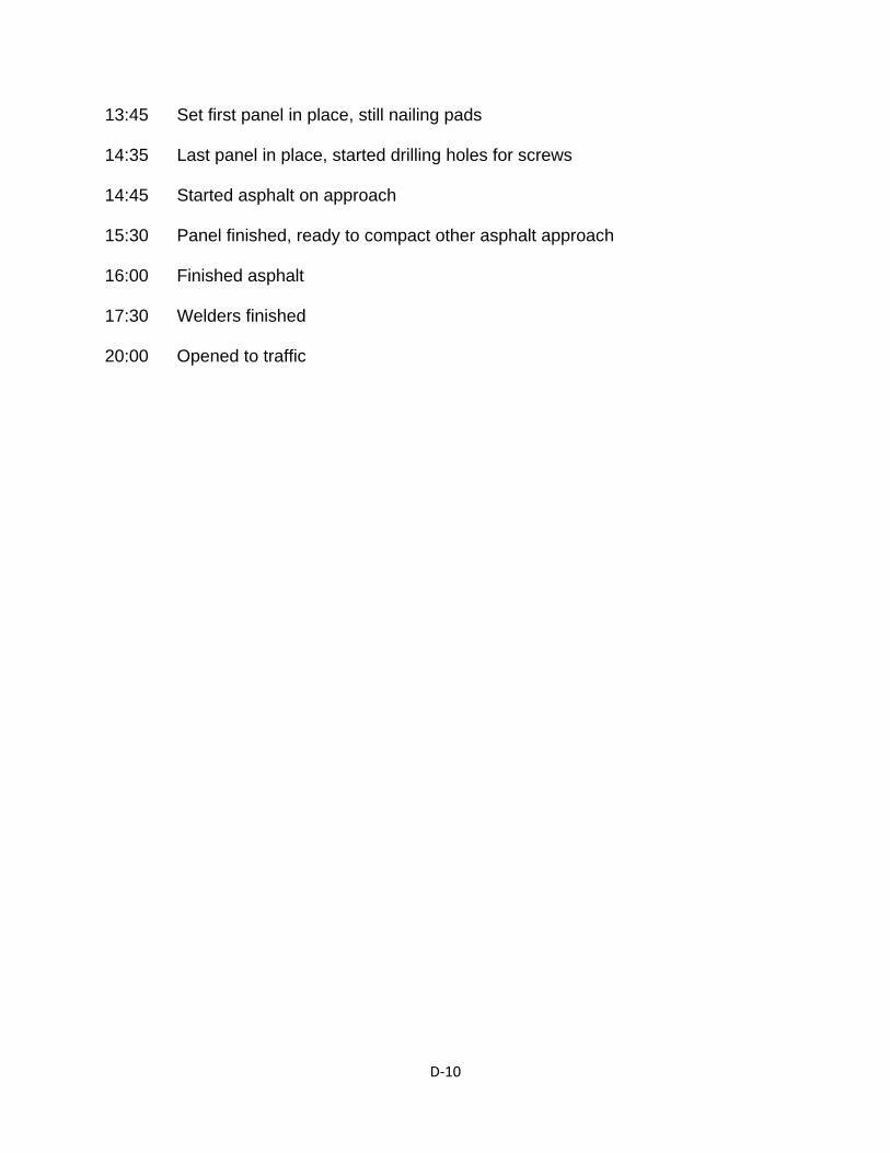
D‐10
13:45 Set first panel in place, still nailing pads 14:35 Last panel in place, started drilling holes for screws 14:45 Started asphalt on approach 15:30 Panel finished, ready to compact other asphalt approach 16:00 Finished asphalt 17:30 Welders finished 20:00 Opened to traffic
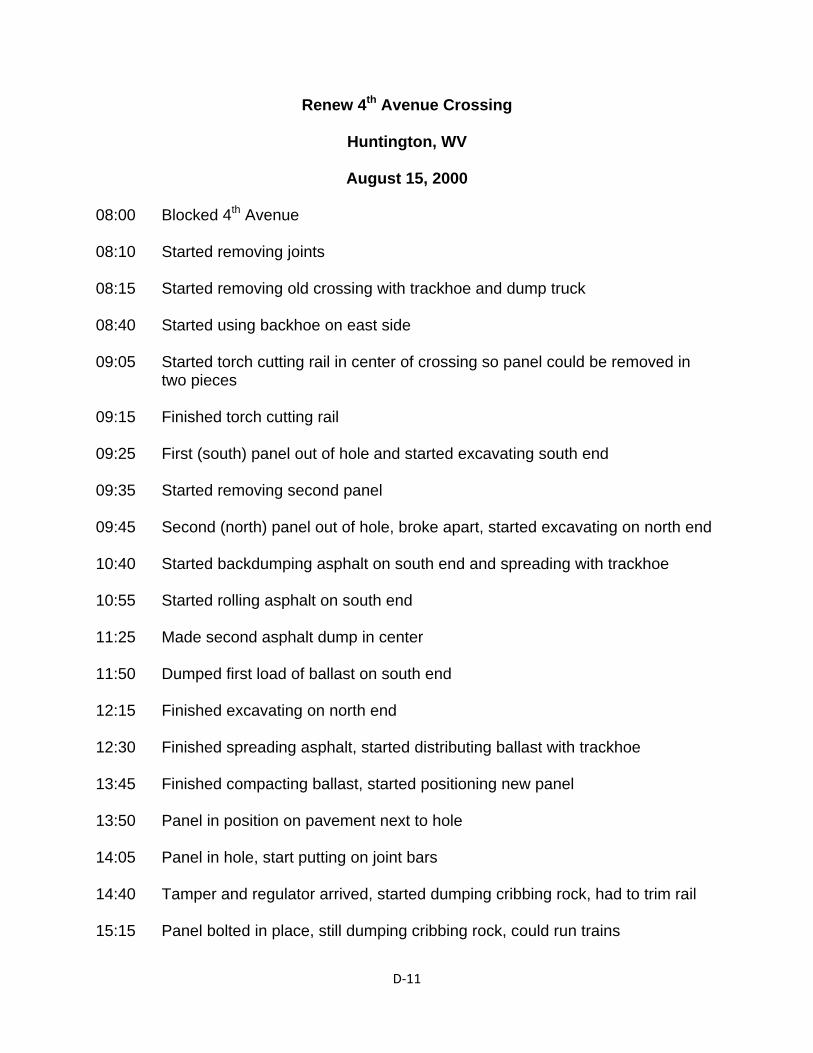
D‐11
Renew 4th Avenue Crossing
Huntington, WV
August 15, 2000 08:00 Blocked 4th Avenue 08:10 Started removing joints 08:15 Started removing old crossing with trackhoe and dump truck 08:40 Started using backhoe on east side 09:05 Started torch cutting rail in center of crossing so panel could be removed in
two pieces 09:15 Finished torch cutting rail 09:25 First (south) panel out of hole and started excavating south end 09:35 Started removing second panel 09:45 Second (north) panel out of hole, broke apart, started excavating on north end 10:40 Started backdumping asphalt on south end and spreading with trackhoe 10:55 Started rolling asphalt on south end 11:25 Made second asphalt dump in center 11:50 Dumped first load of ballast on south end 12:15 Finished excavating on north end 12:30 Finished spreading asphalt, started distributing ballast with trackhoe 13:45 Finished compacting ballast, started positioning new panel 13:50 Panel in position on pavement next to hole 14:05 Panel in hole, start putting on joint bars 14:40 Tamper and regulator arrived, started dumping cribbing rock, had to trim rail 15:15 Panel bolted in place, still dumping cribbing rock, could run trains
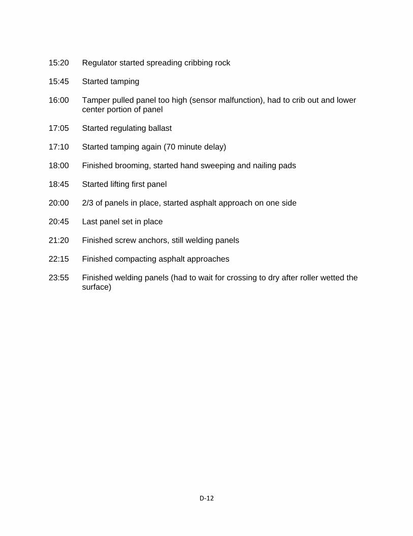
D‐12
15:20 Regulator started spreading cribbing rock 15:45 Started tamping 16:00 Tamper pulled panel too high (sensor malfunction), had to crib out and lower
center portion of panel 17:05 Started regulating ballast 17:10 Started tamping again (70 minute delay) 18:00 Finished brooming, started hand sweeping and nailing pads 18:45 Started lifting first panel 20:00 2/3 of panels in place, started asphalt approach on one side 20:45 Last panel set in place 21:20 Finished screw anchors, still welding panels 22:15 Finished compacting asphalt approaches 23:55 Finished welding panels (had to wait for crossing to dry after roller wetted the
surface)
E‐1
APPENDIX E
Representative Projects
Eastern Kentucky Heavy Tonnage Crossings
KY 550 – Lackey, KY, June 2001
KY 7 – Jim, KY, June 2001
KY 302 – Bull Creek, KY, November 2001
KY 3 – Louisa, KY, October 2001
George’s Branch – Vicco, KY, September 2001
KY 15 – Isom, KY, November 2002
KY 1426 – Banner, KY, November 2001
KY 979 – Harold, KY, November 2001
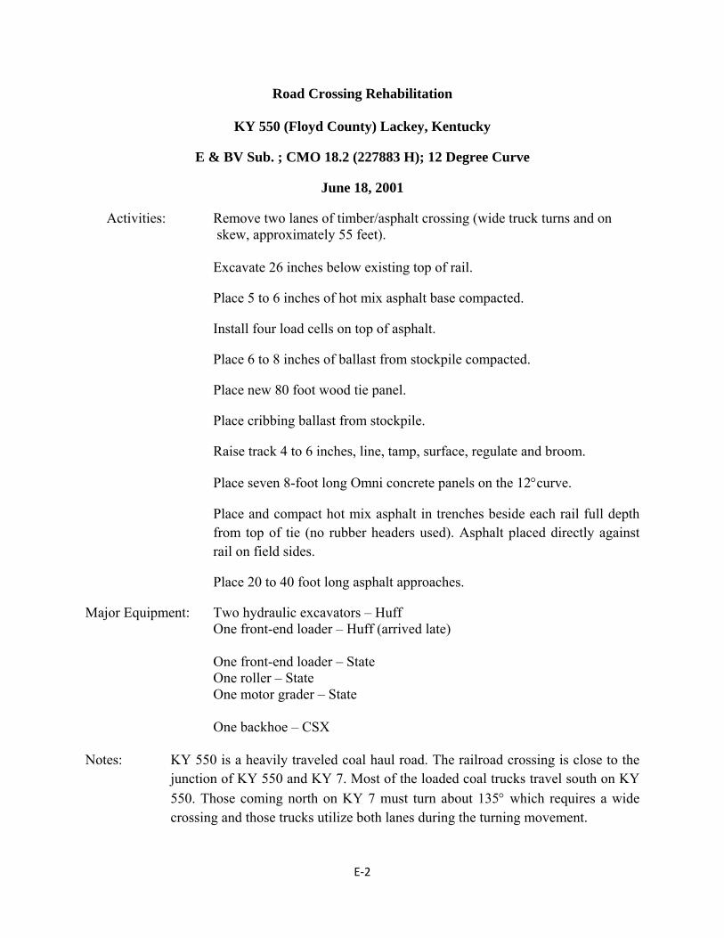
E‐2
Road Crossing Rehabilitation
KY 550 (Floyd County) Lackey, Kentucky
E & BV Sub. ; CMO 18.2 (227883 H); 12 Degree Curve
June 18, 2001
Activities: Remove two lanes of timber/asphalt crossing (wide truck turns and on skew, approximately 55 feet).
Excavate 26 inches below existing top of rail.
Place 5 to 6 inches of hot mix asphalt base compacted.
Install four load cells on top of asphalt.
Place 6 to 8 inches of ballast from stockpile compacted.
Place new 80 foot wood tie panel.
Place cribbing ballast from stockpile.
Raise track 4 to 6 inches, line, tamp, surface, regulate and broom.
Place seven 8-foot long Omni concrete panels on the 12curve.
Place and compact hot mix asphalt in trenches beside each rail full depth from top of tie (no rubber headers used). Asphalt placed directly against rail on field sides.
Place 20 to 40 foot long asphalt approaches.
Major Equipment: Two hydraulic excavators – Huff One front-end loader – Huff (arrived late) One front-end loader – State One roller – State One motor grader – State One backhoe – CSX Notes: KY 550 is a heavily traveled coal haul road. The railroad crossing is close to the
junction of KY 550 and KY 7. Most of the loaded coal trucks travel south on KY
550. Those coming north on KY 7 must turn about 135 which requires a wide crossing and those trucks utilize both lanes during the turning movement.
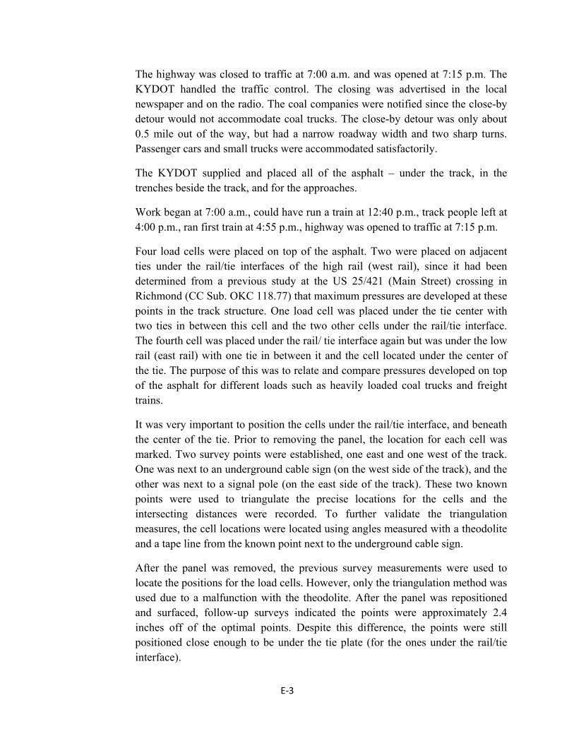
E‐3
The highway was closed to traffic at 7:00 a.m. and was opened at 7:15 p.m. The KYDOT handled the traffic control. The closing was advertised in the local newspaper and on the radio. The coal companies were notified since the close-by detour would not accommodate coal trucks. The close-by detour was only about 0.5 mile out of the way, but had a narrow roadway width and two sharp turns. Passenger cars and small trucks were accommodated satisfactorily.
The KYDOT supplied and placed all of the asphalt – under the track, in the trenches beside the track, and for the approaches.
Work began at 7:00 a.m., could have run a train at 12:40 p.m., track people left at 4:00 p.m., ran first train at 4:55 p.m., highway was opened to traffic at 7:15 p.m.
Four load cells were placed on top of the asphalt. Two were placed on adjacent ties under the rail/tie interfaces of the high rail (west rail), since it had been determined from a previous study at the US 25/421 (Main Street) crossing in Richmond (CC Sub. OKC 118.77) that maximum pressures are developed at these points in the track structure. One load cell was placed under the tie center with two ties in between this cell and the two other cells under the rail/tie interface. The fourth cell was placed under the rail/ tie interface again but was under the low rail (east rail) with one tie in between it and the cell located under the center of the tie. The purpose of this was to relate and compare pressures developed on top of the asphalt for different loads such as heavily loaded coal trucks and freight trains.
It was very important to position the cells under the rail/tie interface, and beneath the center of the tie. Prior to removing the panel, the location for each cell was marked. Two survey points were established, one east and one west of the track. One was next to an underground cable sign (on the west side of the track), and the other was next to a signal pole (on the east side of the track). These two known points were used to triangulate the precise locations for the cells and the intersecting distances were recorded. To further validate the triangulation measures, the cell locations were located using angles measured with a theodolite and a tape line from the known point next to the underground cable sign.
After the panel was removed, the previous survey measurements were used to locate the positions for the load cells. However, only the triangulation method was used due to a malfunction with the theodolite. After the panel was repositioned and surfaced, follow-up surveys indicated the points were approximately 2.4 inches off of the optimal points. Despite this difference, the points were still positioned close enough to be under the tie plate (for the ones under the rail/tie interface).
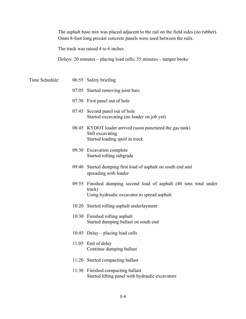
E‐4
The asphalt base mix was placed adjacent to the rail on the field sides (no rubber). Omni 8-foot long precast concrete panels were used between the rails.
The track was raised 4 to 6 inches.
Delays: 20 minutes – placing load cells; 35 minutes – tamper broke
Time Schedule: 06:55 Safety briefing
07:05 Started removing joint bars
07:30 First panel out of hole
07:45 Second panel out of hole Started excavating (no loader on job yet) 08:45 KYDOT loader arrived (soon punctured the gas tank) Still excavating Started loading spoil in truck 09:30 Excavation complete Started rolling subgrade 09:40 Started dumping first load of asphalt on south end and
spreading with loader
09:55 Finished dumping second load of asphalt (40 tons total under track)
Using hydraulic excavator to spread asphalt 10:20 Started rolling asphalt underlayment
10:30 Finished rolling asphalt Started dumping ballast on south end 10:45 Delay – placing load cells
11:05 End of delay Continue dumping ballast 11:20 Started compacting ballast
11:30 Finished compacting ballast Started lifting panel with hydraulic excavators
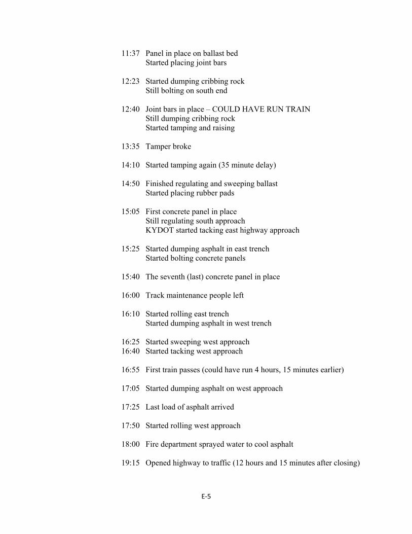
E‐5
11:37 Panel in place on ballast bed Started placing joint bars 12:23 Started dumping cribbing rock Still bolting on south end 12:40 Joint bars in place – COULD HAVE RUN TRAIN Still dumping cribbing rock Started tamping and raising 13:35 Tamper broke 14:10 Started tamping again (35 minute delay) 14:50 Finished regulating and sweeping ballast Started placing rubber pads 15:05 First concrete panel in place Still regulating south approach KYDOT started tacking east highway approach 15:25 Started dumping asphalt in east trench Started bolting concrete panels 15:40 The seventh (last) concrete panel in place 16:00 Track maintenance people left 16:10 Started rolling east trench Started dumping asphalt in west trench 16:25 Started sweeping west approach 16:40 Started tacking west approach 16:55 First train passes (could have run 4 hours, 15 minutes earlier) 17:05 Started dumping asphalt on west approach 17:25 Last load of asphalt arrived 17:50 Started rolling west approach 18:00 Fire department sprayed water to cool asphalt 19:15 Opened highway to traffic (12 hours and 15 minutes after closing)
E‐6
Individuals: Frank Castle – KYDOT District Maintenance Engineer – Pikeville Greg Couch – KYDOT District Traffic Engineer – Pikeville Mark Anuszkiewicz – CSX ADE – Paintsville Gary Caldwell – CSX Roadmaster – Martin Martin Ramsey – Division Engineer – Erwin, TN Michael Hill – Assistant Chief Engr. Admin – Jacksonville Mountain Enterprises – Asphalt Supply – Martin
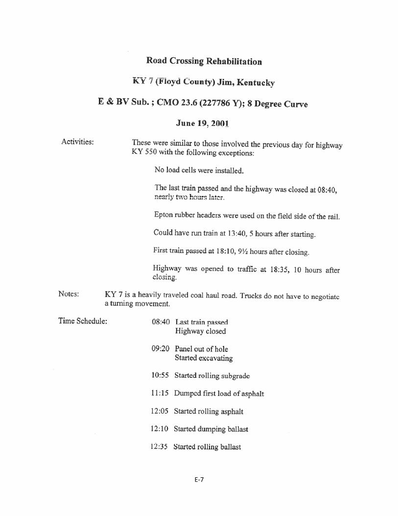
E‐7
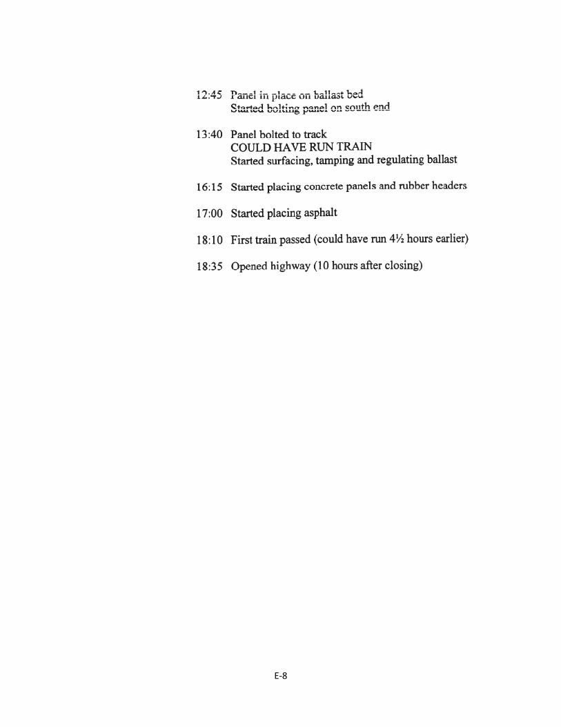
E‐8
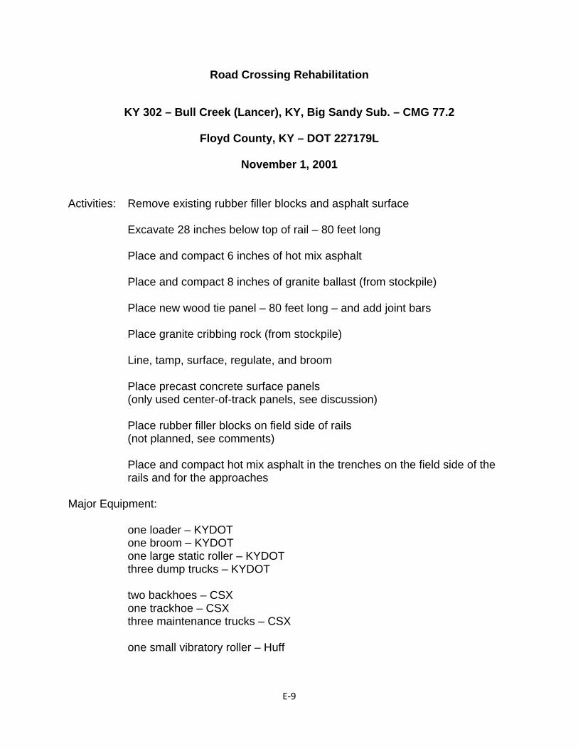
E‐9
Road Crossing Rehabilitation
KY 302 – Bull Creek (Lancer), KY, Big Sandy Sub. – CMG 77.2
Floyd County, KY – DOT 227179L
November 1, 2001
Activities: Remove existing rubber filler blocks and asphalt surface Excavate 28 inches below top of rail – 80 feet long Place and compact 6 inches of hot mix asphalt Place and compact 8 inches of granite ballast (from stockpile) Place new wood tie panel – 80 feet long – and add joint bars Place granite cribbing rock (from stockpile) Line, tamp, surface, regulate, and broom Place precast concrete surface panels (only used center-of-track panels, see discussion) Place rubber filler blocks on field side of rails (not planned, see comments) Place and compact hot mix asphalt in the trenches on the field side of the
rails and for the approaches Major Equipment:
one loader – KYDOT one broom – KYDOT one large static roller – KYDOT three dump trucks – KYDOT two backhoes – CSX one trackhoe – CSX three maintenance trucks – CSX one small vibratory roller – Huff
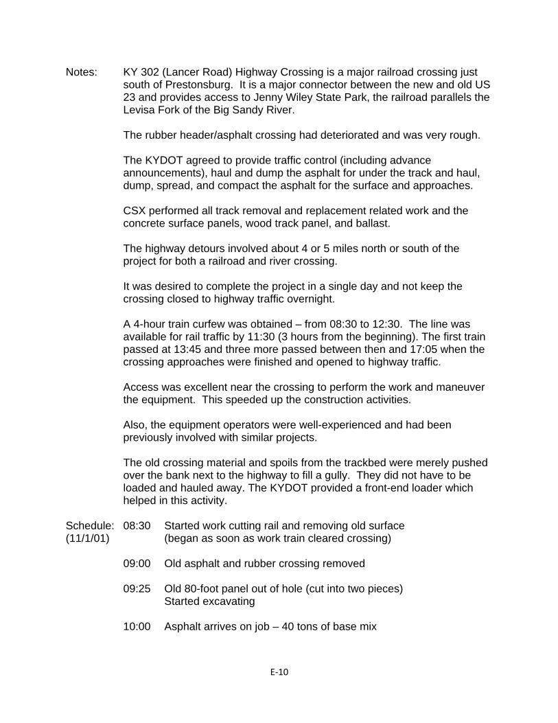
E‐10
Notes: KY 302 (Lancer Road) Highway Crossing is a major railroad crossing just south of Prestonsburg. It is a major connector between the new and old US 23 and provides access to Jenny Wiley State Park, the railroad parallels the Levisa Fork of the Big Sandy River.
The rubber header/asphalt crossing had deteriorated and was very rough.
The KYDOT agreed to provide traffic control (including advance announcements), haul and dump the asphalt for under the track and haul, dump, spread, and compact the asphalt for the surface and approaches.
CSX performed all track removal and replacement related work and the concrete surface panels, wood track panel, and ballast.
The highway detours involved about 4 or 5 miles north or south of the project for both a railroad and river crossing.
It was desired to complete the project in a single day and not keep the crossing closed to highway traffic overnight.
A 4-hour train curfew was obtained – from 08:30 to 12:30. The line was available for rail traffic by 11:30 (3 hours from the beginning). The first train passed at 13:45 and three more passed between then and 17:05 when the crossing approaches were finished and opened to highway traffic.
Access was excellent near the crossing to perform the work and maneuver the equipment. This speeded up the construction activities.
Also, the equipment operators were well-experienced and had been previously involved with similar projects.
The old crossing material and spoils from the trackbed were merely pushed over the bank next to the highway to fill a gully. They did not have to be loaded and hauled away. The KYDOT provided a front-end loader which helped in this activity.
Schedule: 08:30 Started work cutting rail and removing old surface (11/1/01) (began as soon as work train cleared crossing) 09:00 Old asphalt and rubber crossing removed 09:25 Old 80-foot panel out of hole (cut into two pieces) Started excavating 10:00 Asphalt arrives on job – 40 tons of base mix
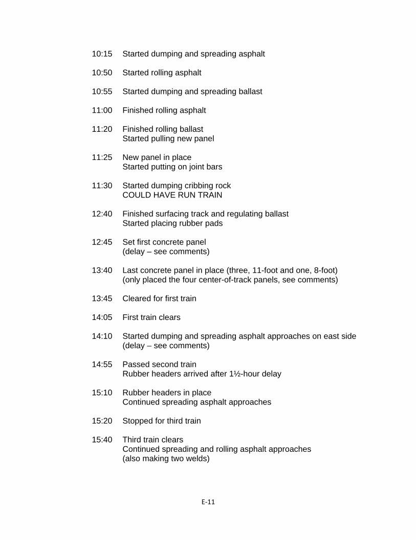
E‐11
10:15 Started dumping and spreading asphalt 10:50 Started rolling asphalt 10:55 Started dumping and spreading ballast 11:00 Finished rolling asphalt 11:20 Finished rolling ballast Started pulling new panel 11:25 New panel in place Started putting on joint bars 11:30 Started dumping cribbing rock COULD HAVE RUN TRAIN 12:40 Finished surfacing track and regulating ballast Started placing rubber pads 12:45 Set first concrete panel (delay – see comments) 13:40 Last concrete panel in place (three, 11-foot and one, 8-foot) (only placed the four center-of-track panels, see comments) 13:45 Cleared for first train 14:05 First train clears 14:10 Started dumping and spreading asphalt approaches on east side (delay – see comments) 14:55 Passed second train Rubber headers arrived after 1½-hour delay 15:10 Rubber headers in place Continued spreading asphalt approaches 15:20 Stopped for third train 15:40 Third train clears Continued spreading and rolling asphalt approaches (also making two welds)
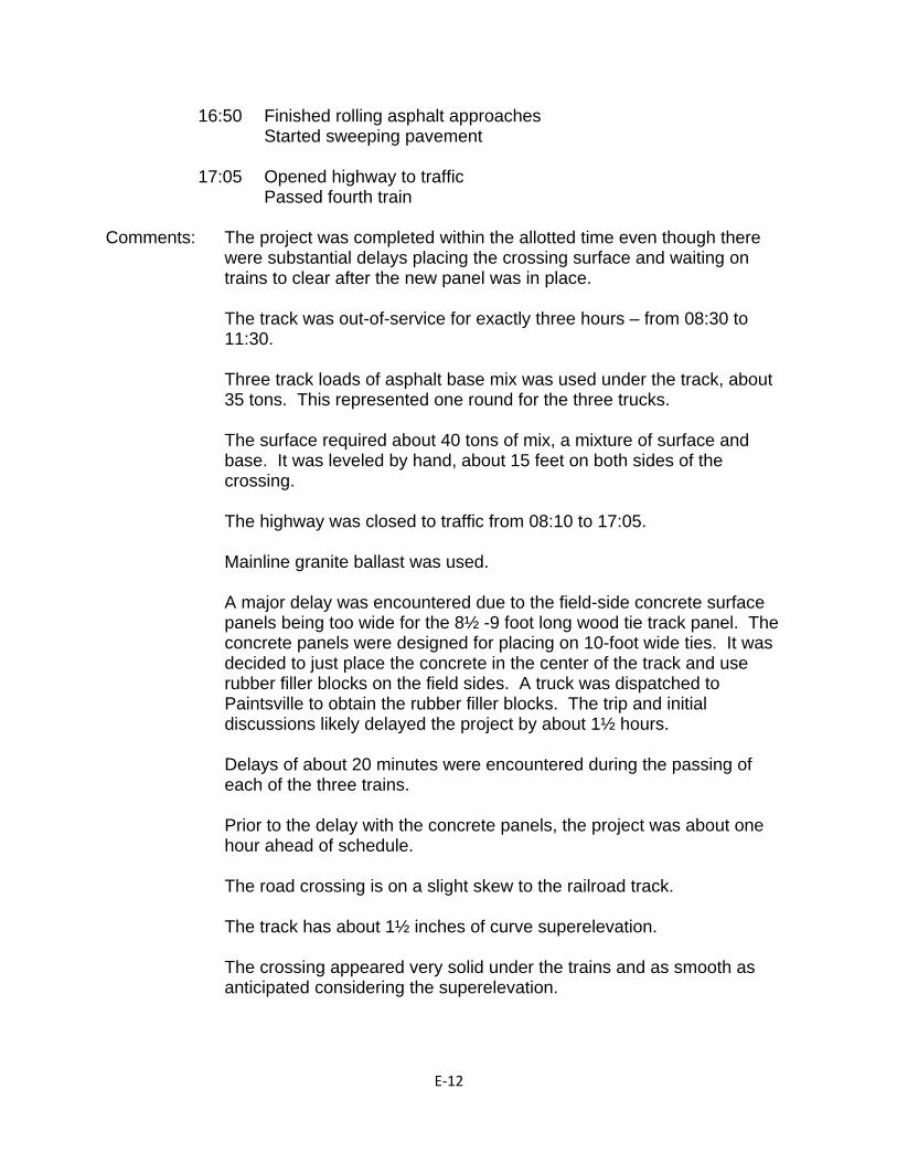
E‐12
16:50 Finished rolling asphalt approaches Started sweeping pavement 17:05 Opened highway to traffic Passed fourth train Comments: The project was completed within the allotted time even though there
were substantial delays placing the crossing surface and waiting on trains to clear after the new panel was in place.
The track was out-of-service for exactly three hours – from 08:30 to 11:30.
Three track loads of asphalt base mix was used under the track, about 35 tons. This represented one round for the three trucks.
The surface required about 40 tons of mix, a mixture of surface and base. It was leveled by hand, about 15 feet on both sides of the crossing.
The highway was closed to traffic from 08:10 to 17:05.
Mainline granite ballast was used.
A major delay was encountered due to the field-side concrete surface panels being too wide for the 8½ -9 foot long wood tie track panel. The concrete panels were designed for placing on 10-foot wide ties. It was decided to just place the concrete in the center of the track and use rubber filler blocks on the field sides. A truck was dispatched to Paintsville to obtain the rubber filler blocks. The trip and initial discussions likely delayed the project by about 1½ hours.
Delays of about 20 minutes were encountered during the passing of
each of the three trains.
Prior to the delay with the concrete panels, the project was about one hour ahead of schedule.
The road crossing is on a slight skew to the railroad track.
The track has about 1½ inches of curve superelevation.
The crossing appeared very solid under the trains and as smooth as anticipated considering the superelevation.

E‐13
Personnel: Frank Castle – KYDOT R/M Chuck Grindstaff – CSX ADE Mark Anuszkiewicz – CSX GM Andy Cummick – CSX R/M Dale Hanshew – CSX
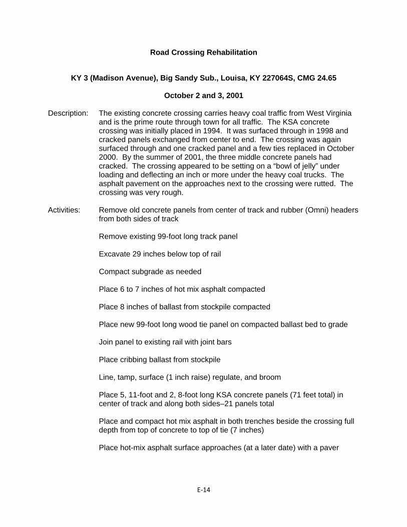
E‐14
Road Crossing Rehabilitation
KY 3 (Madison Avenue), Big Sandy Sub., Louisa, KY 227064S, CMG 24.65
October 2 and 3, 2001
Description: The existing concrete crossing carries heavy coal traffic from West Virginia
and is the prime route through town for all traffic. The KSA concrete crossing was initially placed in 1994. It was surfaced through in 1998 and cracked panels exchanged from center to end. The crossing was again surfaced through and one cracked panel and a few ties replaced in October 2000. By the summer of 2001, the three middle concrete panels had cracked. The crossing appeared to be setting on a “bowl of jelly” under loading and deflecting an inch or more under the heavy coal trucks. The asphalt pavement on the approaches next to the crossing were rutted. The crossing was very rough.
Activities: Remove old concrete panels from center of track and rubber (Omni) headers
from both sides of track
Remove existing 99-foot long track panel
Excavate 29 inches below top of rail Compact subgrade as needed
Place 6 to 7 inches of hot mix asphalt compacted Place 8 inches of ballast from stockpile compacted
Place new 99-foot long wood tie panel on compacted ballast bed to grade
Join panel to existing rail with joint bars
Place cribbing ballast from stockpile
Line, tamp, surface (1 inch raise) regulate, and broom
Place 5, 11-foot and 2, 8-foot long KSA concrete panels (71 feet total) in center of track and along both sides–21 panels total
Place and compact hot mix asphalt in both trenches beside the crossing full depth from top of concrete to top of tie (7 inches)
Place hot-mix asphalt surface approaches (at a later date) with a paver
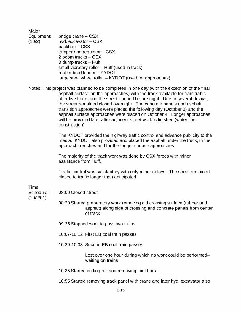
E‐15
Major Equipment: bridge crane – CSX (10/2) hyd. excavator – CSX backhoe – CSX tamper and regulator – CSX 2 boom trucks – CSX 3 dump trucks – Huff small vibratory roller – Huff (used in track) rubber tired loader – KYDOT large steel wheel roller – KYDOT (used for approaches) Notes: This project was planned to be completed in one day (with the exception of the final
asphalt surface on the approaches) with the track available for train traffic after five hours and the street opened before night. Due to several delays, the street remained closed overnight. The concrete panels and asphalt transition approaches were placed the following day (October 3) and the asphalt surface approaches were placed on October 4. Longer approaches will be provided later after adjacent street work is finished (water line construction).
The KYDOT provided the highway traffic control and advance publicity to the media. KYDOT also provided and placed the asphalt under the truck, in the approach trenches and for the longer surface approaches.
The majority of the track work was done by CSX forces with minor assistance from Huff.
Traffic control was satisfactory with only minor delays. The street remained closed to traffic longer than anticipated.
Time Schedule: 08:00 Closed street (10/2/01) 08:20 Started preparatory work removing old crossing surface (rubber and
asphalt) along side of crossing and concrete panels from center of track
09:25 Stopped work to pass two trains
10:07-10:12 First EB coal train passes 10:29-10:33 Second EB coal train passes
Lost over one hour during which no work could be performed– waiting on trains 10:35 Started cutting rail and removing joint bars 10:55 Started removing track panel with crane and later hyd. excavator also
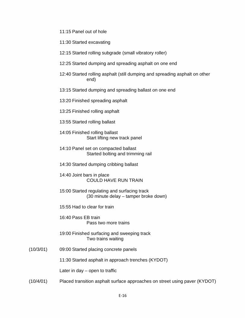
E‐16
11:15 Panel out of hole 11:30 Started excavating 12:15 Started rolling subgrade (small vibratory roller) 12:25 Started dumping and spreading asphalt on one end 12:40 Started rolling asphalt (still dumping and spreading asphalt on other
end) 13:15 Started dumping and spreading ballast on one end 13:20 Finished spreading asphalt 13:25 Finished rolling asphalt 13:55 Started rolling ballast 14:05 Finished rolling ballast Start lifting new track panel 14:10 Panel set on compacted ballast Started bolting and trimming rail 14:30 Started dumping cribbing ballast 14:40 Joint bars in place COULD HAVE RUN TRAIN 15:00 Started regulating and surfacing track (30 minute delay – tamper broke down) 15:55 Had to clear for train 16:40 Pass EB train Pass two more trains 19:00 Finished surfacing and sweeping track Two trains waiting (10/3/01) 09:00 Started placing concrete panels 11:30 Started asphalt in approach trenches (KYDOT) Later in day – open to traffic (10/4/01) Placed transition asphalt surface approaches on street using paver (KYDOT)
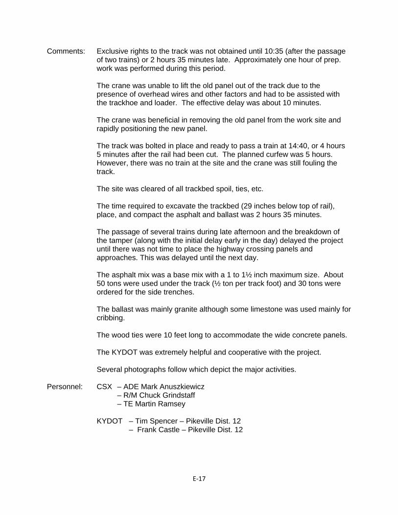
E‐17
Comments: Exclusive rights to the track was not obtained until 10:35 (after the passage of two trains) or 2 hours 35 minutes late. Approximately one hour of prep. work was performed during this period.
The crane was unable to lift the old panel out of the track due to the presence of overhead wires and other factors and had to be assisted with the trackhoe and loader. The effective delay was about 10 minutes.
The crane was beneficial in removing the old panel from the work site and rapidly positioning the new panel.
The track was bolted in place and ready to pass a train at 14:40, or 4 hours 5 minutes after the rail had been cut. The planned curfew was 5 hours. However, there was no train at the site and the crane was still fouling the track.
The site was cleared of all trackbed spoil, ties, etc.
The time required to excavate the trackbed (29 inches below top of rail), place, and compact the asphalt and ballast was 2 hours 35 minutes.
The passage of several trains during late afternoon and the breakdown of the tamper (along with the initial delay early in the day) delayed the project until there was not time to place the highway crossing panels and approaches. This was delayed until the next day.
The asphalt mix was a base mix with a 1 to 1½ inch maximum size. About 50 tons were used under the track (½ ton per track foot) and 30 tons were ordered for the side trenches.
The ballast was mainly granite although some limestone was used mainly for cribbing.
The wood ties were 10 feet long to accommodate the wide concrete panels.
The KYDOT was extremely helpful and cooperative with the project.
Several photographs follow which depict the major activities.
Personnel: CSX – ADE Mark Anuszkiewicz – R/M Chuck Grindstaff – TE Martin Ramsey KYDOT – Tim Spencer – Pikeville Dist. 12 – Frank Castle – Pikeville Dist. 12
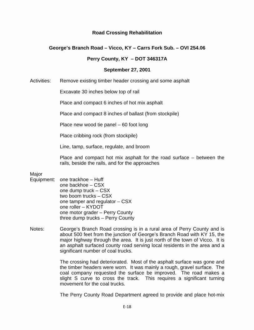
E‐18
Road Crossing Rehabilitation
George’s Branch Road – Vicco, KY – Carrs Fork Sub. – OVI 254.06
Perry County, KY – DOT 346317A
September 27, 2001
Activities: Remove existing timber header crossing and some asphalt Excavate 30 inches below top of rail Place and compact 6 inches of hot mix asphalt Place and compact 8 inches of ballast (from stockpile) Place new wood tie panel – 60 foot long Place cribbing rock (from stockpile) Line, tamp, surface, regulate, and broom Place and compact hot mix asphalt for the road surface – between the
rails, beside the rails, and for the approaches Major Equipment: one trackhoe – Huff one backhoe – CSX one dump truck – CSX two boom trucks – CSX one tamper and regulator – CSX one roller – KYDOT one motor grader – Perry County three dump trucks – Perry County Notes: George’s Branch Road crossing is in a rural area of Perry County and is
about 500 feet from the junction of George’s Branch Road with KY 15, the major highway through the area. It is just north of the town of Vicco. It is an asphalt surfaced county road serving local residents in the area and a significant number of coal trucks.
The crossing had deteriorated. Most of the asphalt surface was gone and the timber headers were worn. It was mainly a rough, gravel surface. The coal company requested the surface be improved. The road makes a slight S curve to cross the track. This requires a significant turning movement for the coal trucks.
The Perry County Road Department agreed to provide and place hot-mix
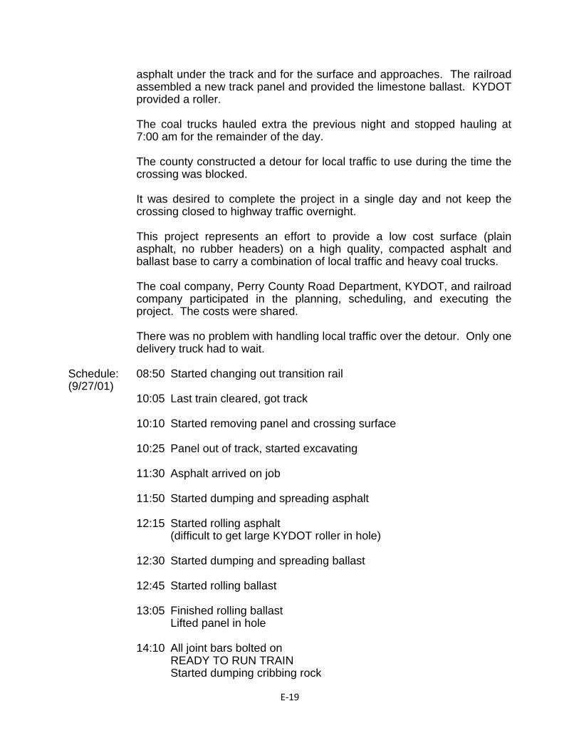
E‐19
asphalt under the track and for the surface and approaches. The railroad assembled a new track panel and provided the limestone ballast. KYDOT provided a roller.
The coal trucks hauled extra the previous night and stopped hauling at 7:00 am for the remainder of the day.
The county constructed a detour for local traffic to use during the time the crossing was blocked.
It was desired to complete the project in a single day and not keep the crossing closed to highway traffic overnight.
This project represents an effort to provide a low cost surface (plain asphalt, no rubber headers) on a high quality, compacted asphalt and ballast base to carry a combination of local traffic and heavy coal trucks.
The coal company, Perry County Road Department, KYDOT, and railroad company participated in the planning, scheduling, and executing the project. The costs were shared.
There was no problem with handling local traffic over the detour. Only one delivery truck had to wait.
Schedule: 08:50 Started changing out transition rail (9/27/01) 10:05 Last train cleared, got track 10:10 Started removing panel and crossing surface 10:25 Panel out of track, started excavating
11:30 Asphalt arrived on job
11:50 Started dumping and spreading asphalt
12:15 Started rolling asphalt (difficult to get large KYDOT roller in hole) 12:30 Started dumping and spreading ballast 12:45 Started rolling ballast 13:05 Finished rolling ballast Lifted panel in hole 14:10 All joint bars bolted on READY TO RUN TRAIN Started dumping cribbing rock
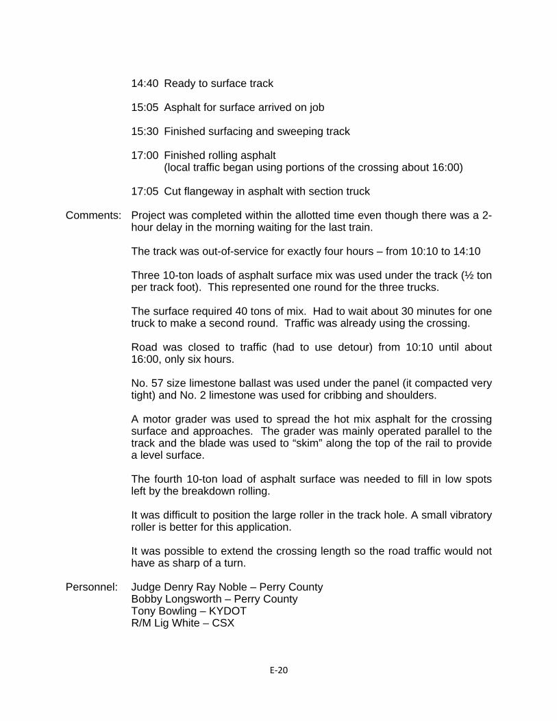
E‐20
14:40 Ready to surface track 15:05 Asphalt for surface arrived on job 15:30 Finished surfacing and sweeping track 17:00 Finished rolling asphalt (local traffic began using portions of the crossing about 16:00) 17:05 Cut flangeway in asphalt with section truck Comments: Project was completed within the allotted time even though there was a 2-
hour delay in the morning waiting for the last train.
The track was out-of-service for exactly four hours – from 10:10 to 14:10
Three 10-ton loads of asphalt surface mix was used under the track (½ ton per track foot). This represented one round for the three trucks.
The surface required 40 tons of mix. Had to wait about 30 minutes for one truck to make a second round. Traffic was already using the crossing.
Road was closed to traffic (had to use detour) from 10:10 until about 16:00, only six hours.
No. 57 size limestone ballast was used under the panel (it compacted very tight) and No. 2 limestone was used for cribbing and shoulders.
A motor grader was used to spread the hot mix asphalt for the crossing surface and approaches. The grader was mainly operated parallel to the track and the blade was used to “skim” along the top of the rail to provide a level surface.
The fourth 10-ton load of asphalt surface was needed to fill in low spots left by the breakdown rolling.
It was difficult to position the large roller in the track hole. A small vibratory roller is better for this application.
It was possible to extend the crossing length so the road traffic would not have as sharp of a turn.
Personnel: Judge Denry Ray Noble – Perry County Bobby Longsworth – Perry County Tony Bowling – KYDOT R/M Lig White – CSX
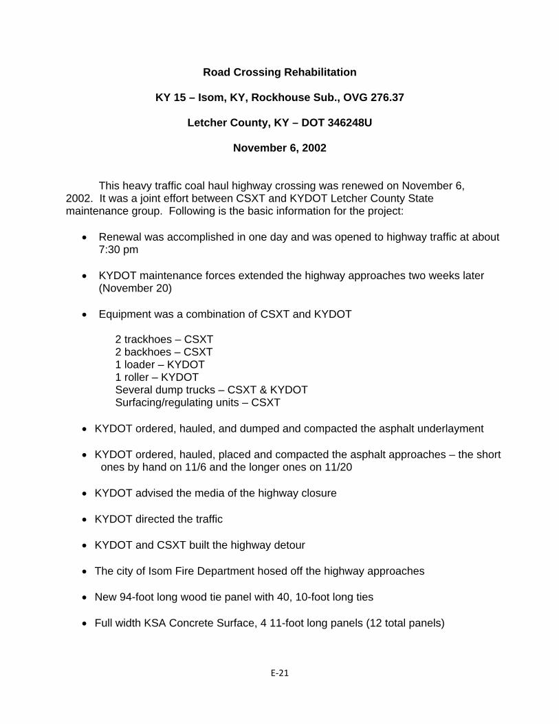
E‐21
Road Crossing Rehabilitation
KY 15 – Isom, KY, Rockhouse Sub., OVG 276.37
Letcher County, KY – DOT 346248U
November 6, 2002
This heavy traffic coal haul highway crossing was renewed on November 6, 2002. It was a joint effort between CSXT and KYDOT Letcher County State maintenance group. Following is the basic information for the project:
Renewal was accomplished in one day and was opened to highway traffic at about 7:30 pm
KYDOT maintenance forces extended the highway approaches two weeks later
(November 20)
Equipment was a combination of CSXT and KYDOT
2 trackhoes – CSXT 2 backhoes – CSXT 1 loader – KYDOT 1 roller – KYDOT Several dump trucks – CSXT & KYDOT Surfacing/regulating units – CSXT
KYDOT ordered, hauled, and dumped and compacted the asphalt underlayment
KYDOT ordered, hauled, placed and compacted the asphalt approaches – the short ones by hand on 11/6 and the longer ones on 11/20
KYDOT advised the media of the highway closure
KYDOT directed the traffic
KYDOT and CSXT built the highway detour
The city of Isom Fire Department hosed off the highway approaches
New 94-foot long wood tie panel with 40, 10-foot long ties
Full width KSA Concrete Surface, 4 11-foot long panels (12 total panels)
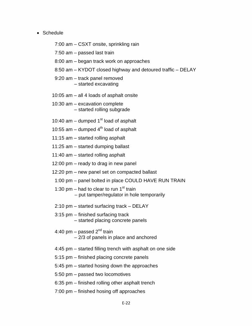
E‐22
Schedule
7:00 am – CSXT onsite, sprinkling rain
7:50 am – passed last train
8:00 am – began track work on approaches
8:50 am – KYDOT closed highway and detoured traffic – DELAY
9:20 am – track panel removed – started excavating 10:05 am – all 4 loads of asphalt onsite
10:30 am – excavation complete – started rolling subgrade 10:40 am – dumped 1st load of asphalt
10:55 am – dumped 4th load of asphalt
11:15 am – started rolling asphalt
11:25 am – started dumping ballast
11:40 am – started rolling asphalt
12:00 pm – ready to drag in new panel
12:20 pm – new panel set on compacted ballast
1:00 pm – panel bolted in place COULD HAVE RUN TRAIN
1:30 pm – had to clear to run 1st train – put tamper/regulator in hole temporarily 2:10 pm – started surfacing track – DELAY
3:15 pm – finished surfacing track – started placing concrete panels 4:40 pm – passed 2nd train – 2/3 of panels in place and anchored 4:45 pm – started filling trench with asphalt on one side
5:15 pm – finished placing concrete panels
5:45 pm – started hosing down the approaches
5:50 pm – passed two locomotives
6:35 pm – finished rolling other asphalt trench
7:00 pm – finished hosing off approaches
E‐23
7:30 pm – opened the highway to traffic The project was completed in one day and was opened to highway traffic during the night. There were delays in beginning the work and due to passing trains of about 2 to 3 hours. All of the spoils were hauled away. KYDOT placed longer approaches two weeks later on November 20.
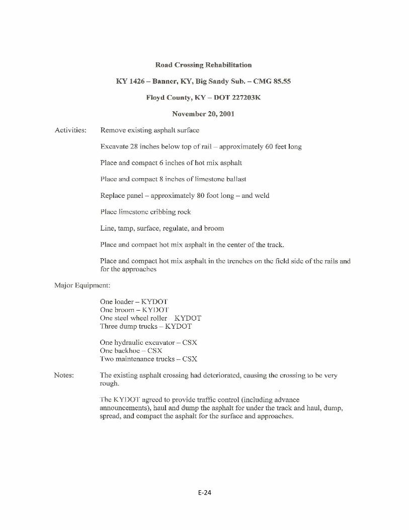
E‐24
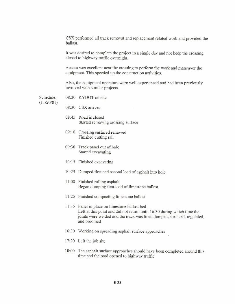
E‐25
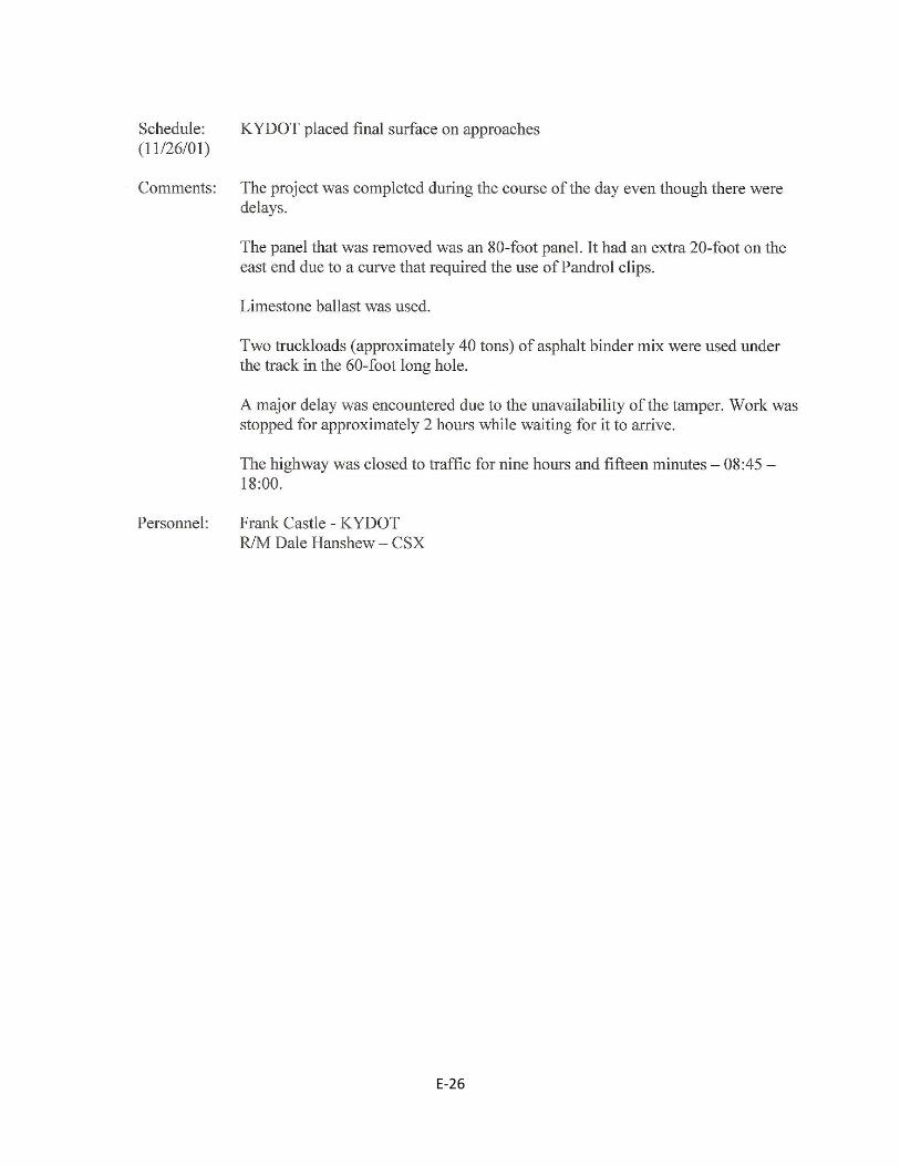
E‐26
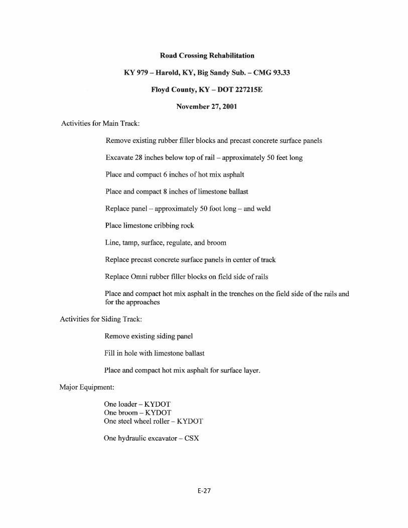
E‐27
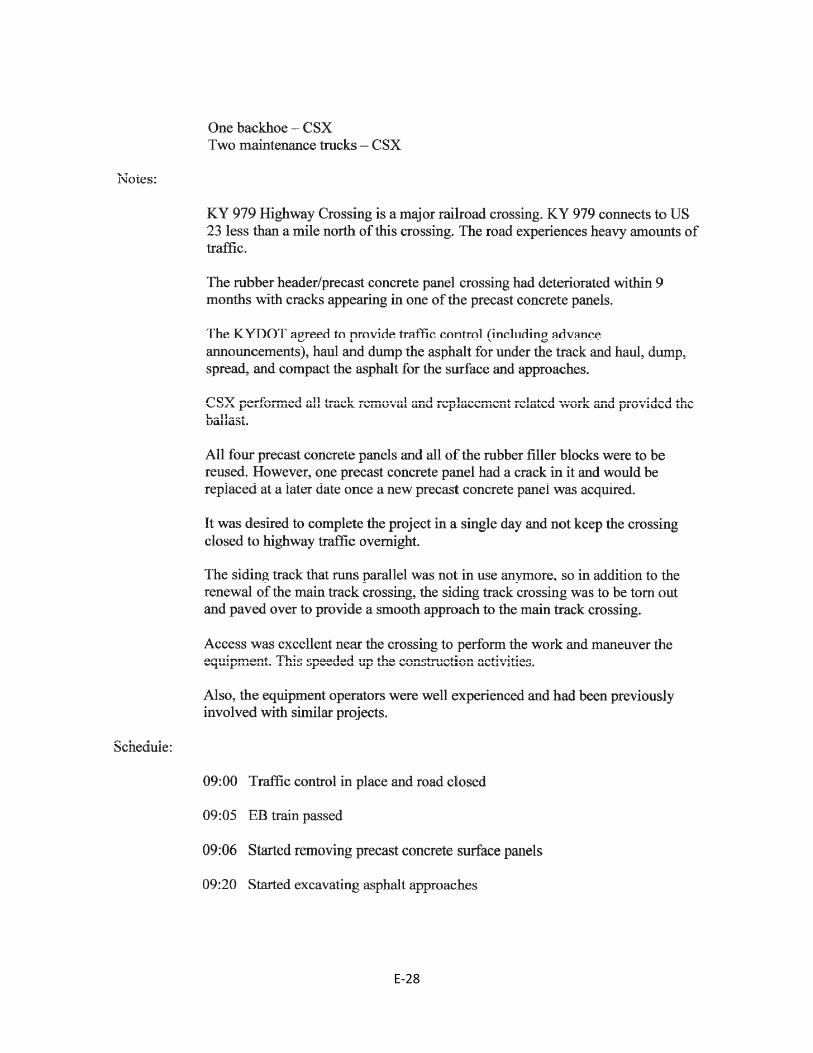
E‐28
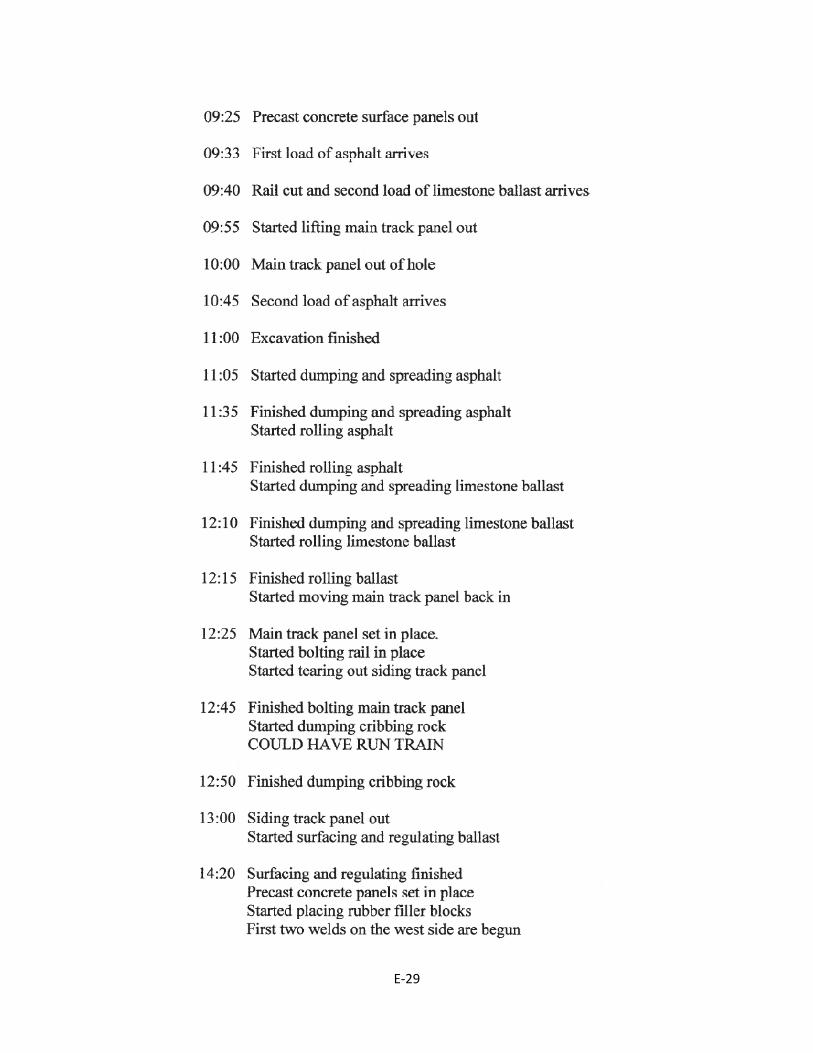
E‐29
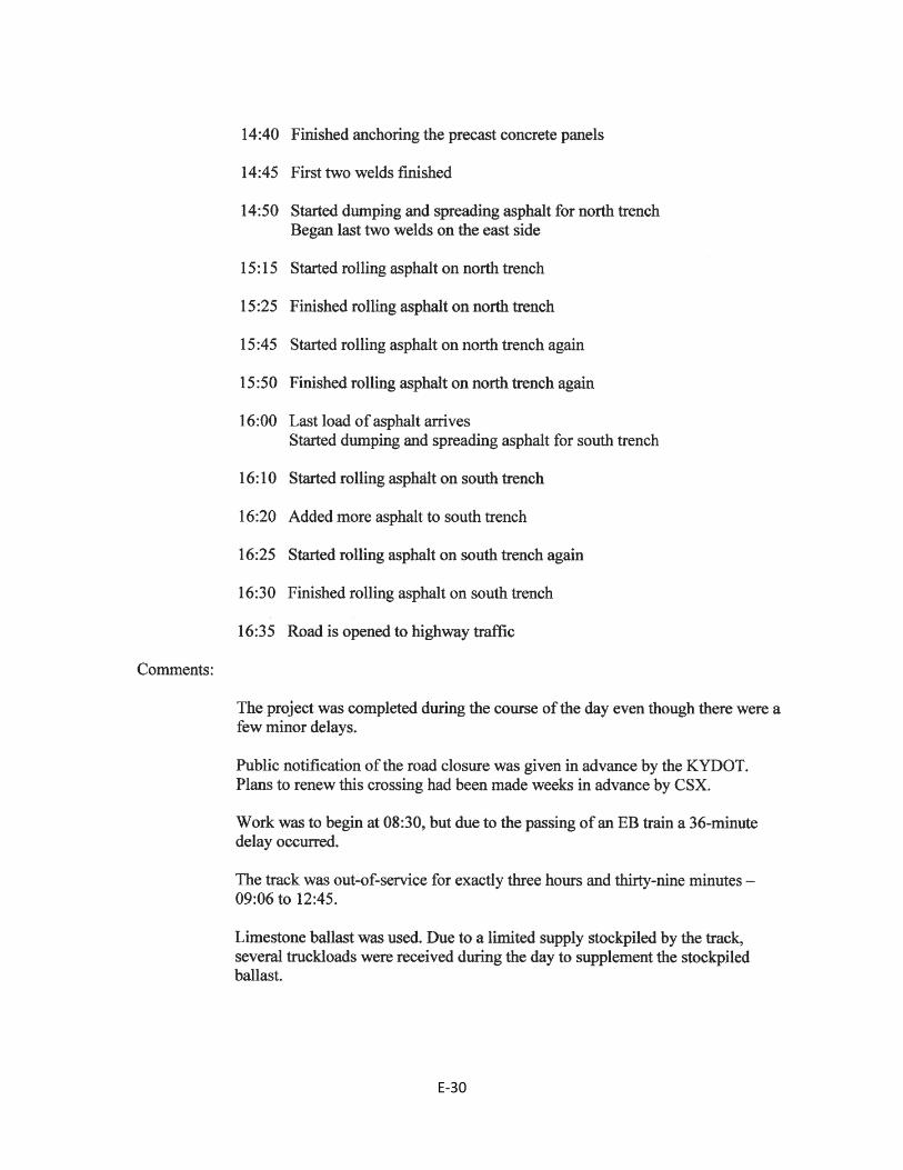
E‐30
E‐31
For more information or a complete publication list, contact us at:
176 Raymond BuildingUniversity of Kentucky
Lexington, Kentucky 40506-0281
(859) 257-4513(859) 257-1815 (FAX)
1-800-432-0719www.ktc.uky.edu
KENTUCKY TRANSPORTATION CENTER
The University of Kentucky is an Equal Opportunity Organization